Embed Size (px)
Citation preview
International Journal of Dynamics of Fluids.
ISSN 0973-1784 Volume 12, Number 1 (2016), pp. 37-56
© Research India Publications
http://www.ripublication.com
Design and Analysis of an Axial Fan used
in Kiln Shell Cooling
Parasaram Sarath Chandra1, Dr. K. Sivaji Babu2 and U. Koteswara Rao3
M.Tech (Machine Design) Research student1, PVPSIT, Kanuru, India.
Principal2, Department of Mechanical Engineering, PVPSIT, Kanuru, India.
Associate Professor3, Department of Mechanical Engineering, PVPSIT, Kanuru, India.
Abstract
The design of high efficient fans is often based on the experience of the
designer. Based on the integral parameters of the flow and the geometry of an
axial flow fan; a performance analysis of it has been performed. The main scope
of the design process of axial fans, employs either airfoil theory or more direct
design methods is to deliver high efficiency blades. Three aerofoils have been
studied for the application and finally a combination of airfoil literally called F-
series had been used in the present work. An existing axial fan has been
considered for efficiency improvement where airfoil theory in combination with
free vortex design method, is used for a design advantage.
The effectiveness of the design procedure is verified with CFD simulation. The
experience acquired from the analysis of the performance of the preliminary
design, came in handy in later stages of design in order to achieve the best
efficiency possible, which is an iterative process. The target of improved static
efficiency (higher than 67%) has been achieved and it’s been calculated as 71%.
Performance of the design fan has been investigated by means of ANSYS CFX,
a commercial CFD software. In this paper, theoretical results obtained are
compared by drawing a performance curve, with those results obtained CFD
simulation.
Keywords: Turbomachines, axial fans, aerofoils, free vortex theory, CFD

38 Parasaram Sarath Chandra, Dr. K. Sivaji Babu and U. Koteswara Rao
I. INTRODUCTION
Modern cement plants needs a wide range of process fans. Process critical fans can be
mainly classified as centrifugal and axial type of fans. Here, the author employs the
design of axial fan used to cool a clinker rotary kiln shell. Overall capacity of the plant
is generally determined by the capacity of clinker rotary kiln. So, the mechanics of
rotary kiln cylinder is paid close attention on engineering sites due to its frequent
damage and expensive maintenance cost.
The main focus of the paper was to design and analyse an axial fan with improvised
efficiency, by using an industrial example for demonstration purpose and establish a
systematical design procedure which predicts the fan performance where usage of
computational fluid dynamics (CFD) will be instrumental. High volume flow and low
pressure fans are used in cooling applications for several process equipment and also
for ventilation of silo cones, mines etc. Present paper focuses on a specific application,
related to clinker kiln-shell cooling.
Present work deals with axial flow fan of type power absorbing turbomachines. The
flow in the investigated form, i.e., air, is characterised by Mach numbers below the
compressibility limit (< 0.3). It is a clear case that fan operating with incompressible
flow, which is a type of high capacity, low head (pressure), and single stage axial flow
type turbomachine.
Fans are a kind of equipment where we can use engineering strategies and optimize the
energy consumption without effecting their efficiency. An axial flow fan can achieve
high efficiencies as with an optimum blade settings and is only slightly lower than that
obtained with the backward inclined aerofoil centrifugal fan and much better than
convectional fans [18].
To cool a kiln-shell used in cement plant needs a fan with specific speeds which works
for given site conditions. Selection of a fan and design of an impeller needs a keen study
of rotor blade design which is majorly based on velocity components. The blade may
be of simply a plate with camber angles or an aerofoil shape [4]. Research is suggesting
that replacing the curved camber plate with the aerofoil blade may produce almost
identical performance but which results in the considerable increase in the total
efficiency as well as in structural strength of the blade.
Designing an efficient airfoil profile implies that the shape which thus acquired has to
be aerodynamically efficient. A comprehensive aerodynamic treatment of it, has been
presented in the present work. Airfoil and the blade so designed are analysed using
commercial CFD software called ANSYS CFX. The main emphasis will be on
improvement of efficiency and the system performance.
The design of high efficient fan is often based on the experience of a designer. In order
to determine the dimensions of a fan, one can use either Cordier diagram or background
curves. Cordier diagram [9] provides an optimum dimensions for a fan as a system,
whereas through background curves, system and blade geometries could be
approximately estimated and refined for actual design point based on well-established

Design and Analysis of an Axial Fan used in Kiln Shell Cooling 39
design procedure. The present paper sees, the use of both in a blend for optimum values
and to attain best efficiency point.
Fan characteristics can be described by consistent parameters such as volume flow rate,
pressure, power, and efficiency.
An industrial example, upon industrial study, has been considered for the demonstration
of the design flow. Based on specifications of site conditions and flow requirements, a
preliminary calculations has been made which defined the system resistance. From
these considerations a specific valve of fan diameter has obtained, by using Cordier
diagram which was verified with background fan curves for an optimal value.
II. DESIGN APPROACH
A. Fan Theory
The rotor design is a function of swirl coefficient and flow coefficient. Swirl is an
important measure of rotor torque. In this method, static and total pressure were
normalized by using non-dimensional terms of axial velocity and dynamic pressure.
Based upon initial calculation of pressures, velocity of air, speed of an impeller within
the system resistance with trial and error method will give non-dimentionalized factors
like load factor, specific speed and specific diameter. Load factor was determined to be
1.15, shown in figure 1
Fig. 1 load factor vs static pressure
If the fan and hub diameter are known, then the total pressure rise and the volumetric
flow rate can be converted into non-dimensional quantities. It is possible to estimate
the fan diameter and hub diameter using Cordier diagram [9] which needs a parameter
called specific speed.

40 Parasaram Sarath Chandra, Dr. K. Sivaji Babu and U. Koteswara Rao
Specific speed; Ns = 𝑁 . 𝑄1
2 . 𝛥𝑃−3
4
Where N is the fan rotational speed in rpm, Q is the volumetric flow rate in m3/s and
ΔP is the total pressure rise across the fan in Pascal.
The general momentum equation can be written in Z and Y direction and given as
follows:
𝑍 = [𝜌. 𝑠. 𝑑𝑟. 𝑉𝑎12 − ∫ 𝜌
𝑠
0
. 𝑑𝑟. 𝑉𝑎22. 𝑑𝑦] + [ 𝑝1. 𝑠. 𝑑𝑟 − ∫ 𝑝2. 𝑑𝑟. 𝑑𝑦]
𝑠
0
Y s. dr. Va1. V1] [∫ ρ. drVa2. Vθ2dy]s
0 E
Z and Y are the forces acting on the blade element of length ‘dr’ for constant inlet
velocity. ‘E’ in equation related to ‘Y’ is the shear stress term due to wake flow shown
in Figure 2.
Assume, as the E is negligible with constant velocity, and at Y direction pressure at
inlet and exit do not tend to change. The simplified relations are as follows;
Z = (p1-p2). s. dr
Y = 𝜌. 𝑠. Va. (Vθ1 - Vθ2). dr
Fig. 2 Flow representation with cascade in a blade [3]

Design and Analysis of an Axial Fan used in Kiln Shell Cooling 41
Thus exerted, theoretical pressure can be given as follow;
pth p2 p1 w
Where, ‘w’ is the mean total pressure loss due to the presence of wake, which is
assumed as negligible in this case.
The efficiency of the fan unit is influenced by the amount of swirl left in the air after it
has passed the last stage of blading in the unit. The swirl momentum can play no part
in overcoming the resistance of the duct system unless the associated tangential
component is removed and its velocity head converted into static pressure. Furthermore
as per Wallis [3], wake consideration is not necessary factor in fan design but a
considerable understanding should be needed for studying the effects of noise and blade
vibration.
Theoretical head rise w.r.t present design considerations could be written as;
𝛥𝑃
0.5 𝜌. 𝑉𝑎2 = 𝑘ℎ − 𝑘𝑅
Swirl coefficient which is a measure of rotor torque can be defined as the ratio of the
swirl velocity and the axial velocity at a given radius.
𝜀 = 𝑉𝜃
𝑉𝑎
Flow coefficient can be defined as, the ratio of the axial velocity and rotational rotor
speed at a given radius.
𝜆 = 𝑉𝑎
𝛺. 𝑟
So, the theoretical pressure rise coefficient can be given as;
𝐾ℎ = (2
𝜆) . 𝜀
The relative velocity and absolute velocity factors play key role in estimating pressure
ratios, blade angle while designing a blade. As per the free vortex theory, the axial
velocity component is constant throughout the fan annulus. There is no radial velocity
component and the pressure rise is constant in radial direction [6].
Axial velocity is calculated from the continuity equation.
𝑉𝑎(𝑢) = 𝐴𝑓𝑎𝑛 . 𝑉𝑓𝑎𝑛
𝐴𝑎𝑛𝑛𝑢𝑙𝑢𝑠=
𝑄𝑓𝑎𝑛
𝜋4 . (𝐷𝑓𝑎𝑛
2 − 𝐷ℎ𝑢𝑏2 )
The flow over the rotor blades can be represented by either absolute velocities or
relative velocities. The schematics of velocity vectors for relative and absolute
velocities are shown in figure 3.

42 Parasaram Sarath Chandra, Dr. K. Sivaji Babu and U. Koteswara Rao
Fig. 3 Absolute velocity vector [6]
The relative flow angles with respect to the rotor blades are calculated by using
equations;
𝛽1 = atan (1
𝜆)
𝛽2 = atan (1 − 𝜀
𝜆)
tan(𝛽𝑚) = 0.5(tan(𝛽1) + tan(𝛽2))
The thrust and torque exerted on the flow by the rotor blades can be calculated by using
the following equations. The torque acting on the rotor shaft can be expressed in terms
of the swirl momentum added to the stream.
𝑇 = 𝑇𝑐 ∗ 0.5 (𝜌 . 𝑢 . 𝜋 . 𝑟𝑡𝑖𝑝3 )
𝑇𝑐 = 4 .𝑥3
3 . 𝜀
The main interest in design with the thrust produced by the rotor is in relation to the
design of thrust bearings and supports. This could be compensated with an estimate
based on the pressure rise across the rotor and the swept area.
𝑇ℎ = 𝑇ℎ𝑐 ∗ 0.5 ∗ (𝜌 . 𝑢2 . 𝜋. 𝑟𝑡𝑖𝑝2 )
𝑇ℎ =𝛥𝑝. 𝑥. 𝑟
0.5. (𝜌. 𝑢2)

Design and Analysis of an Axial Fan used in Kiln Shell Cooling 43
B. Procedure and calculations
The fan design is an iterative process. For starting the calculations with efficiency
assumed to 89% as an initial guess. With blading design in process, efficiency is
calculated and checked for convergence. Diffusion efficiency was considered as 80%.
Static pressure recovery is assumed as 80%. Tip clearance was chosen to be 2.5% of
blade span.
Table -1 Specifications
Specification of a fan
Volumetric flow, m3/s 5
Static pressure, Pa 300
Density, Kg/m3 1.07
Speed, rpm 1450
Fan diameter, m 0.8
Hub to tip ratio has been chosen for feasible hub diameters from minimum hub diameter
to the maximum possible one. Minimum hub diameter can be given as,
dmin = 30.5932 . √𝑃𝑠
𝑟𝑝𝑚
Among five different feasible combinations of hub to tip ratios (x), one was chosen
based on best efficiency, and estimates on component losses in the fan unit and a
prediction of overall efficiency with an appropriate convergence. Estimates to loss in
components had been followed by a graphical procedure prescribed by Wallis [6]. Later
rotor design with moments based on non-dimensional coefficients with the dimensional
quantities, as computed by the modified isolated airfoil theory which uses free vortex
design method.
With these respects, hub to tip ratio was selected to be 0.5 which gave 71% total to
static efficiency an increase of 4% with the existing one which is a significant one when
implemented in industry.
The efficiency loss due to profile drag Cdp, were aimed at keeping either the blade
element efficiency or the lift coefficient constant along the blade.
The blade lift and drag coefficients are related by equation, blade loading;
𝐶𝑙 . 𝜎 = 2 . 𝜀 . cos (𝛽𝑚)
Solidity; σ = (c/s)
From the two empirical equations above, Cl is obtained which is an approximation of
total lift coefficient. The chord has been chosen with a view to keeping the blade aspect
ratio approximately 2.
Primary drag coefficient is found to be 0.011 for the design of hub to tip ratio of 0.5.

44 Parasaram Sarath Chandra, Dr. K. Sivaji Babu and U. Koteswara Rao
Secondary drag coefficient is an estimate based on the consideration of airfoil and
cambered plate with constant thickness assumptions.
𝐶𝑑𝑠 = 0.018 ∗ 𝐶𝑙2 − − − −→ 𝑓𝑜𝑟 𝑎𝑖𝑟𝑓𝑜𝑖𝑙
So the total drag coefficient is, 𝐶𝑑 = 𝐶𝑑𝑝 + 𝐶𝑑𝑠
As the free vortex design assumption, the total head rise coefficient and the axial
velocity component, are both constant along the blade span.
Rotor loss coefficient is calculated by following equation;
𝐾𝑅
𝐾ℎ=
𝜆
𝐶𝑙
𝐶𝑑 cos (𝛽𝑚)
Finally efficiency can be calculated by equation;
𝜂 = 1 −𝐾𝑅
𝐾ℎ
The detailed design of fan blade elements is followed by radial distribution pattern
across the annulus. At first chord length is assumed as half the length of the span as
aspect ratio was assumed as 2; which gives an appropriate Reynolds number by
equation:
𝑅𝑒 = 𝑤𝑟 . 𝑐/𝑣
Where, v is the velocity of air at S.T.P.
Airfoil selection is primarily based on Reynolds number, thickness ratio, and chord
length, maximum camber in chord percentage, lift and pressure coefficients. C4, NACA
4 digit and NACA 5 digit were compared and finally a combination of NACA 5digit
nose droop with C4 profile called as F-series in literature has been selected for use in
construction of blade.
A sample profile of the F-Series aerofoil was presented in below figure 4.
Fig. 4 Airfoil shape depicted using Matlab

Design and Analysis of an Axial Fan used in Kiln Shell Cooling 45
III. CFD SIMULATION
ANSYS CFX has been used for CFD simulation of the product designed. To bring the
simulation results closer to real-life operating conditions, to a CAD model at the inlet
of the impeller a rig section which is long enough that the flow entering the impeller
domain can be considered as a fully developed with the 3 Dpipe, and at the outlet where
an ambient condition prevails another pipe with a length of 2 Dpipe was included. Its
pictorial depiction was shown in below figure 5.
A. Boundary conditions
We need to define the velocity inlet as a boundary condition at the inlet section and
pressure exit at the outlet section. After a steady state solution is obtained, the pressure
difference is calculated by using the surface integral options of the fluent program. This
option is more reliable and enhances a good control of volumetric flow.
Fig. 5 CAD model of full system
The inlet boundary with specified velocity was applied to the rig domain, flow direction
normal to the boundary condition and medium turbulence intensity (5%). A rotational
speed of 1450 rpm was applied to the fan domain. The outlet boundary was applied to
the ambient domain by specifying a 250C temperature with an air density of 1.07 kg
/m3.
Since some part of the fluid zone is defined by a moving reference frame and some part
of the fluid is stationary, grid interface panel is used to define the interactions.
The turbulence model used in the solution is selected as RNG k-ε model. With reference
to [18], has satisfactory results using the RNG k-ε turbulence model in designing of a
reversible axial flow fan. This model is used for complex shear flows having rapid
gradients, moderate swirl, vortices and local translations. Standard wall functions are
used and the swirl dominated flow option is activated.

46 Parasaram Sarath Chandra, Dr. K. Sivaji Babu and U. Koteswara Rao
B. CFD RESULTS
Alongside with static pressure contours, velocity contours are also presented in figures
6 and 7. As the fan is designed according to the assumption of free vortex theory, which
state no flow zone exists in radial direction.
Fig. 6 Pressure contour at suction side
Fig 7 Pressure contour at pressure side

Design and Analysis of an Axial Fan used in Kiln Shell Cooling 47
A typical CAD model of the airfoil and the flow domain around it was illustrated below
in figure 8.
Fig. 8 Model of flow domain around an airfoil (adapted from [10])
Boundary conditions are key to play a simulation for an appropriate result that should
be satisfactory. So, care has been taken while considering boundary conditions. At the
inlet section, the specified flow velocity which is nothing but an axial velocity acting
over a meridional section of a blade profile, which is calculated to be 16 m/s.
Outlet of the domain was open boundary, which is true with the case to have an ambient
pressure. On to the lateral surfaces, symmetry boundary has been set, over to the top
and bottom of the domain is also a symmetry boundary. As up on observation, after a
height of the domain of 20 times the chord length from top to bottom, the difference in
results between applying symmetry and / or opening boundary will sought to be
negligible. The simulations were carried out for viscous flow with air as ideal gas.
While coming to mesh properties, O-grid structured topology had been applied for the
block corresponding to the profile with a choice of tetrahedral mesh, which is a
convenient option for better results.
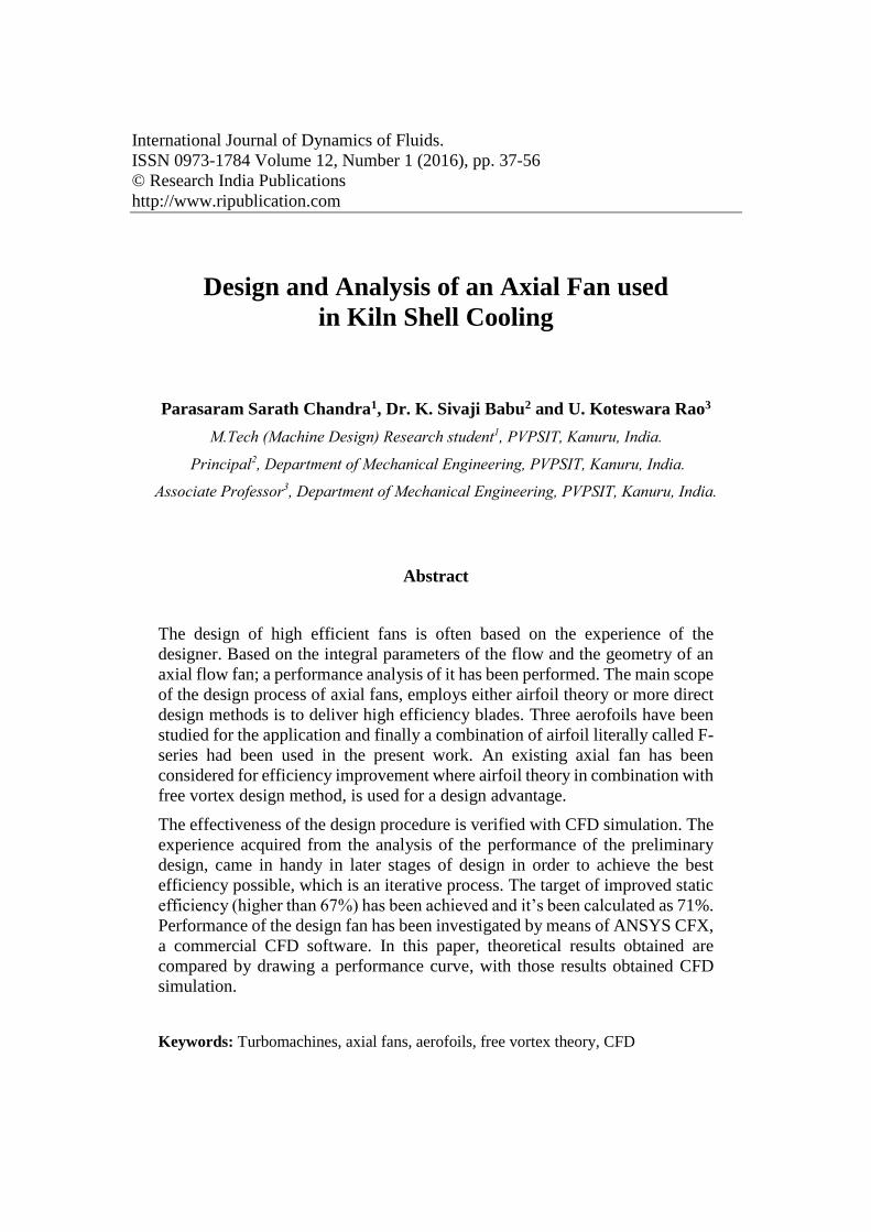
As the case is up on static pressure variation with flow rate, a qualitative appreciation
of pressure contours have been depicted in figure 9, which are helpful while identifying
different sources of losses in the system; where the leading edge of the blade and the
areas close to the tip section are critical due to tip clearance.
48 Parasaram Sarath Chandra, Dr. K. Sivaji Babu and U. Koteswara Rao
Fig. 9 Pressure contour of modified airfoil (f series)
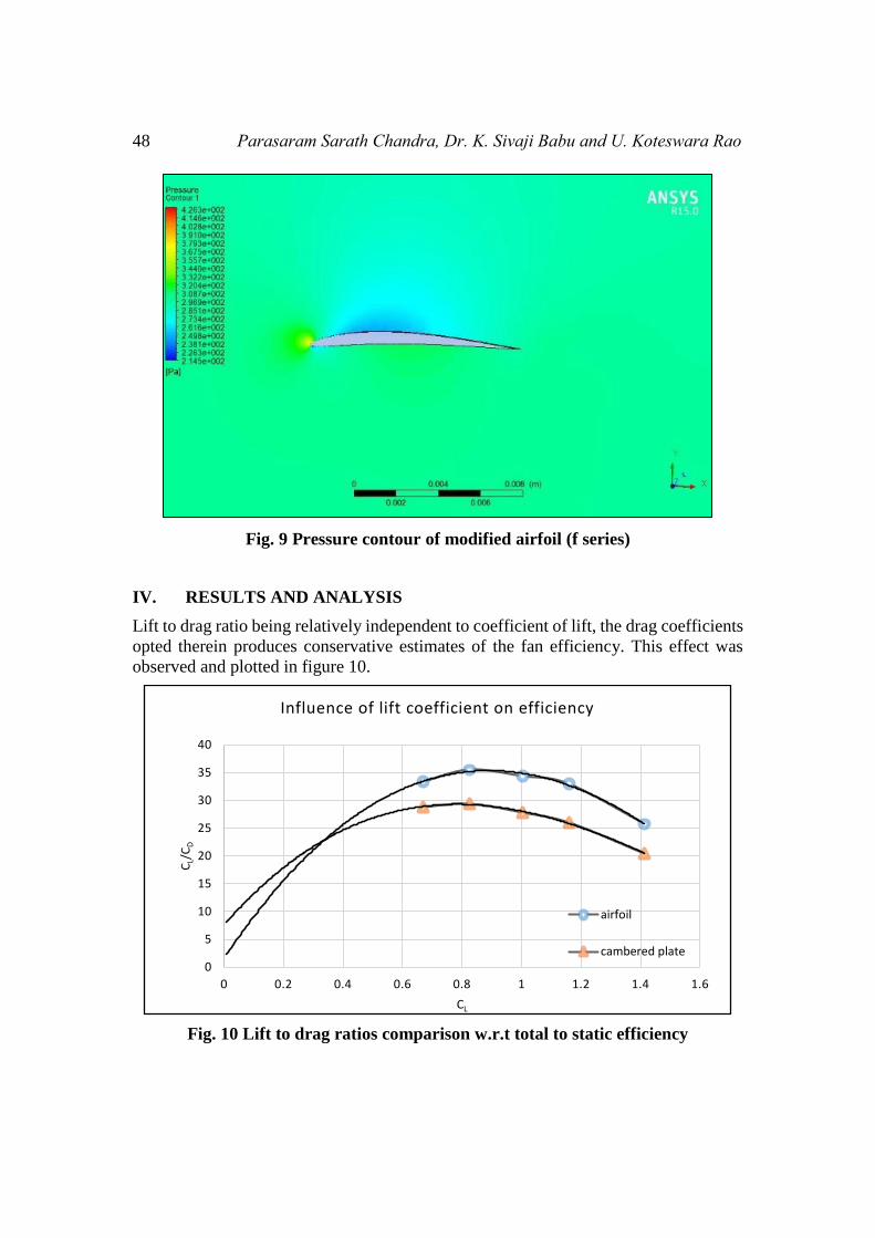
IV. RESULTS AND ANALYSIS
Lift to drag ratio being relatively independent to coefficient of lift, the drag coefficients
opted therein produces conservative estimates of the fan efficiency. This effect was
observed and plotted in figure 10.
Fig. 10 Lift to drag ratios comparison w.r.t total to static efficiency
0
5
10
15
20
25
30
35
40
0 0.2 0.4 0.6 0.8 1 1.2 1.4 1.6
CL/
CD
CL
Influence of lift coefficient on efficiency
airfoil
cambered plate

Design and Analysis of an Axial Fan used in Kiln Shell Cooling 49
The rotor efficiency one way or the other depends mainly on the ratio [Cl\ (Cdp + Cds)].
This ratio is plotted in above figure as a function of Cl and Cd on the assumption that
Cds is proportional to Cl2. Hence design values of Cl approaching unity appear to give
optimum performance when profile drag remains constant. But in practice, Cdp will
increase moderately with Cl, so as an optimal value generally it is less than 0.8. Through
optimal value of Cl efficiency losses of profile and secondary drag can be evaluated in
the design process. For cambered plate blades, as observed, from the loss in efficiency
will be up to 50 per cent greater than that of aerofoils generally used.
The below figure 11 presents the pitch to chord ratio across the radii for the rotor. The
variation of the pitch to chord ratio is high in the rotor designed and as a result the blade
has to be tapered. A tapered blade possesses a smaller chord as one moves from hub to
tip.
Fig. 11.a Radial distribution of pitch to chord ratio
Fig. 11.b Variation of the solidity along the radius of the blade
0
0.05
0.1
0.15
0.2
0.25
0.3
0.35
0.4
0.45
0 0.5 1 1.5 2 2.5 3 3.5 4
Rad
ius
(r)
Pitch-chord ratio
Radial distribution of s/c
0
0.5
1
1.5
2
2.5
0.2 0.25 0.3 0.35 0.4 0.45
Solid
ity σ
r [m]
Variation of solidity with blade radius

50 Parasaram Sarath Chandra, Dr. K. Sivaji Babu and U. Koteswara Rao
The below figure 12 illustrates the relative velocities angles of the blade w.r.t radial
distribution. The variation of the air angles (beta1, beta2) across the radii is in a good
agreement with Wallis recommendations.
Fig. 12 Radial distribution of velocity angles
If in any case, the fan continues to operate outside of the stall region of its performance
curve, air flow will continue to increase as if the chord angle increases from about 20°
to 60°. As to the industrial data ought from industry, many existing fan systems are
operating in unknown areas of their performance curve and a change in chord angle
gives unpredictable results. Here in figure 13, the flow is increased rapidly as the chord
angle is increased from approximately 40°.
Fig. 13 Change of airflow with blade chord angle
0.1
0.15
0.2
0.25
0.3
0.35
0.4
0.45
50 55 60 65 70 75 80
Rad
ius
(r)
Velocity angles
Radial distribution of velocity angles
beta1
beta2

Design and Analysis of an Axial Fan used in Kiln Shell Cooling 51
Fig. 14 Radial distribution of flow and work coefficients
Fig. 15 Radial distribution of flow and swirl coefficient
The distribution of the flow and work coefficients across the radii has been plotted in
above figure 15. Both values decrease as we move from hub to tip.
Radial distribution of flow and swirl coefficients has been presented here in figure 15.
Fan rotor design is mostly variable driven, which can be estimated as a function of the
flow and swirl coefficients. In present work, these are extensively used in congruence

52 Parasaram Sarath Chandra, Dr. K. Sivaji Babu and U. Koteswara Rao
with graphical representations, where the coordinates varies along y-axis and the flow
coefficient. These graphs facilitates enough for design purposes of present work. These
play key role in process of estimating efficiency. A series of iterative formulations have
been in use for collection of data required to plot these graphs.
However, from the design perspective it is important to make sure about the proposed
model that need to perform better according to the flow analysis, which needs
performance analysis.
The fan design point can be defined as 300 Pascal of static pressure which relates to a
total pressure of 361 Pascal with a volumetric flow rate of 5 m³/s.
The efficiency is calculated by the equation below;
𝜂ℎ𝑦𝑑 = 𝑃𝑡𝑜𝑡𝑎𝑙 . 𝑄
𝑇 . 𝜔
Where the numerator is the fluid power and denominator is the shaft power. Table 2
presents the CFD results for 1450 rpm rotor and compared with design point.
The moment about the shaft axis is calculated to be 18.45 Nm as magnitude, which
constitutes to get an efficiency of 63.18% of total hydraulic efficiency which is against
65% of design value raising to 2.8% of error in efficiency which is an acceptable one
according to Lohner [20]. The hydraulic efficiency value is lower than the analytical
value. It is mainly because of the cascade data for F series aerofoils are not sufficient.
But 63.18% is still an acceptable and good value for axial flow fan about this size when
compared to the 52% of total efficiency of the previous reference fan model.
Fig. 16 Performance curve of present design
0
0.5
1
1.5
2
2.5
3
3.5
4
4.5
5
0
100
200
300
400
500
600
700
800
0 1 2 3 4 5 6 7 8
Stat
c p
ress
ure
Pa
Dischage m3/s
charecteristic curve
Resistancesp
bkw
Design point

Design and Analysis of an Axial Fan used in Kiln Shell Cooling 53
Table-2 Gauge total pressures of rotor
Q
(m3/s)
Ptotal
(Pascal)
T (Nm)
CFD 5 354 18.45
Design 5 361 17.937
The designed axial fan will be operated at open condition for kiln-shell cooling which
causes force convection to the wall of kiln-shell, which when compared with other
applications, the operating range can deliberated to be a very narrow case.
The results of simulation are presented in graphical form in Figure 17. Static pressure
rise and efficiency values are plotted with respect to the volumetric flow rate. As
described previously, the operating range of the fan is very narrow, so the calculations
do not cover fan stall regions, closed valve regions and zero pressure loss regions.
𝑒𝑟𝑟𝑜𝑟 =|𝑃𝐶𝐹𝐷 − 𝑃𝑎𝑛𝑎𝑙𝑦𝑡𝑖𝑐𝑎𝑙|
𝑃𝑎𝑛𝑎𝑙𝑦𝑡𝑖𝑐𝑎𝑙 . 100
An error can be defined as the difference of pressure rise between analytical result and
computational result as a percentage of the analytical result. The error is calculated as
1.19 %.
This simulation is used as a validation tool for the design and congruency met by the
simulation result with the analytical value is good enough to consider for practical
application.
Fig. 17 Fan performance curves
54 Parasaram Sarath Chandra, Dr. K. Sivaji Babu and U. Koteswara Rao
V. CONCLUSIONS
The total pressure rise through the rotor is in agreement with the analytical design.
However, total to static efficiency is computed to be 71% as against 67% of the existing
fan.
The pressure contours of the CFD results are also in agreement with free vortex flow.
The pressure contours are aligned from hub to tip in a parallel way. In addition, when
the operating condition is different from the design point the pressure contours
deteriorates.
Cooling is an important factor and it must be taken into consideration for Kiln shells.
Cooling with air exchange may not be an option, if the environment temperature is high.
Cooling option through corner vanes or diffusers can be studied for future work.
By using the design approach model presented in this paper, not only for kiln-shell
cooling but also can be useful for scientific wind tunnels in subsonic regimes or
automobile fans, which can be designed and built. The design in this manuscript is for
given site conditions, if the location is different, the duct or tube axial fan design must
be optimized for these conditions. The terminal velocity, which derives the design,
changes nonlinearly with altitude. This situation must be taken into account during
design.
CFD is used to analyse the total pressure increase and static pressure rise across the
rotor of the fan. Since the operating region is far from the fan stall point, flow separation
or instabilities had not been investigated. Although CFD is a powerful tool for flow
analysis, it must be backed up by experimental data which could be a future scope of
this work.
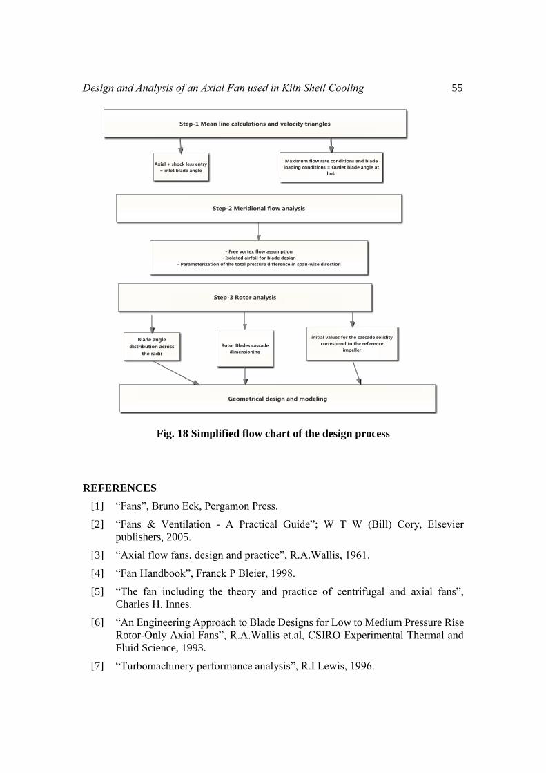
In brief, with / of design approach has been presented in figure 18; which later CFD
simulation follows with a numerical analysis and has been presented with graphical and
contour plots as results in above sections.
Design and Analysis of an Axial Fan used in Kiln Shell Cooling 55
Fig. 18 Simplified flow chart of the design process
REFERENCES
[1] “Fans”, Bruno Eck, Pergamon Press.
[2] “Fans & Ventilation - A Practical Guide”; W T W (Bill) Cory, Elsevier
publishers, 2005.
[3] “Axial flow fans, design and practice”, R.A.Wallis, 1961.
[4] “Fan Handbook”, Franck P Bleier, 1998.
[5] “The fan including the theory and practice of centrifugal and axial fans”,
Charles H. Innes.
[6] “An Engineering Approach to Blade Designs for Low to Medium Pressure Rise
Rotor-Only Axial Fans”, R.A.Wallis et.al, CSIRO Experimental Thermal and
Fluid Science, 1993.
[7] “Turbomachinery performance analysis”, R.I Lewis, 1996.

56 Parasaram Sarath Chandra, Dr. K. Sivaji Babu and U. Koteswara Rao
[8] “Developments in Turbomachinery Flow” by Nader Montazerin et.al.
[9] “A theoretical derivation of the Cordier diagram for turbomachines”; Epple
et.al, Journal of Mechanical Engineering Science, 2011.
[10] “Axial fan design: modern layout and design strategy for fan performance
optimization” by Maria Pascu
[11] “The Design and Performance of an Axial-Flow Fan”; Lionel s. Marks et.al,
AER-53-13, transactions of the american society of mechanical engineers,
1934.
[12] “Analytical Models for Axial Fan Performance Rating”; Daniel Khalitov,
Ganesh. R; AMCA Engineering Conf, Las Vegas, NV, 2008
[13] “A Comparison of Two Methods for Predicting the Potential Flow around
Arbitrary Airfoils in Cascade”; D. Pollurd and J. Wordsworth, 1963.
[14] “Fluid machinery: application, selection, and design”; Gerhart and Wright, 2nd
edition, 2009.
[15] “Design and Analysis of Propeller Blade Geometry using the PDE Method” by
Christopher Wojciech Dekanski, Phd thesis.
[16] “A Parametric Blade Design System”; Hans Heukenkamp lecture notes
[17] “Airfoil Aerodynamics Using Panel Methods” by Richard L. Fearn
[18] “Centrifugal and axial fan applications and design criteria” by I.Howitt
[19] “Principles of turbomachinery”; R.K.Turton, 2nd edition, 1995.
[20] “Applied computational fluid dynamics techniques”; Rainald Löhner, 6th
edition, 2008.
[21] AMCA standard 210.
[22] IS 3588 & 4894.
[23] ANSYS CFX Reference Guide.