Embed Size (px)
Citation preview
NAVEEN KUMAR D, et al, International Journal of Research Sciences and Advanced Engineering [IJRSAE]TM Volume 2, Issue 16, PP: 266 - 277, OCT-DEC’ 2016.
International Journal of Research Sciences and Advanced Engineering
Vol.2 (16), ISSN: 2319-6106, OCT - DEC’ 2016. PP: 266 - 277
DESIGN AND ANALYSIS OF BRIDGE DESIGN USING SAP 2000
D NAVEEN KUMAR 1*, S B SANKAR RAO 2*, P MALLESHAM 3*
1. II.M.Tech , Dept of CIVIL, SRI INDU COLLEGE OF ENGINEERING & TECHNOLOGY.
2. Head - Dept of CIVIL, SRI INDU COLLEGE OF ENGINEERING & TECHNOLOGY.
3. Principal, SRI INDU COLLEGE OF ENGINEERING & TECHNOLOGY.
Abstract
The response of bridges under a moving vehicle is complex due to the interaction between bridge and the
vehicle. As the bridge deck surface deteriorates over time, the road surface roughness profile will vary
accordingly. The varying surface roughness profiles over time will generate increased dynamic loads on
the bridge decks through dynamic interaction between surface roughness, vehicles of heavy traffic and
bridge structures. The present study aims to characterize the effects of the time-varying dynamic loads
from heavy traffic and bridge performance.
The paper presents the results of dynamic analysis of both the concrete girder bridge and infers which
type will be dynamically stable. Both bridges contain AASHTO type girders and were designed to carry
two lanes of HS20 loading. The vehicular load was HS-20 truckloads, designed to deliver the ultimate
live load specified by the AASHTO Code. The dynamic load were performed with the vehicle traveling at
23 m/s, 46 m/s, and 92 m/s speed.
Keywords – Sap 2000, Concrete Girder Bridge, Dynamic Analysis, moving loads
INTRODUCTION
A bridge is a structure built to span physical
obstacles such as a body of water, valley, or
road, for the purpose of providing passage over
the obstacle. There are many different designs
that all serve unique purposes and apply to
different situations. Designs of bridges vary
depending on the function of the bridge, the
nature of the terrain where the bridge is
constructed and anchored, the material used to
make it, and funds available to build it.
The first bridges were made by nature itself as
simple as a log fallen across a stream or stones
in the river. The first bridges made by humans
were probably spans of cut wooden logs or
planks and eventually stones, using a simple
support and crossbeam arrangement. Some early
Americans used trees or bamboo poles to cross
small caverns or wells to get from one place to
another. A common form of lashing sticks, logs,
and deciduous branches together involved the
use of long reeds or other harvested fibers
woven together to form a connective rope
capable of binding and holding together the
materials used in early bridges.
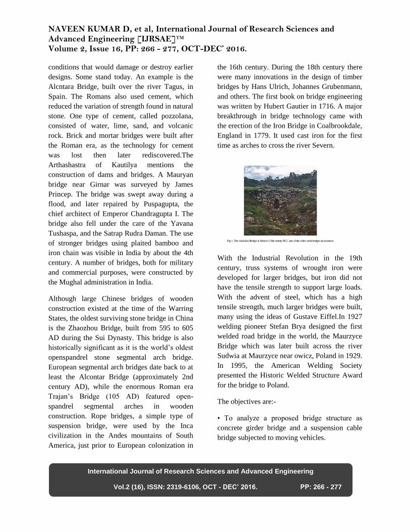
The Arkadiko Bridge is one of four Mycenaean
corbel arch bridges part of a former network of
roads, designed to accommodate chariots,
between Tiryns and Epidauros in the
Peloponnese, in Greece. Dating to the Greek
Bronze Age (13th century BC), it is one of the
oldest arch bridges still in existence and use.
Several intact arched stone bridges from the
Hellenistic era can be found in the Peloponnese
in southern Greece.
The greatest bridge builders of antiquity were
the ancient Romans. The Romans built arch
bridges and aqueducts that could stand in
NAVEEN KUMAR D, et al, International Journal of Research Sciences and Advanced Engineering [IJRSAE]TM Volume 2, Issue 16, PP: 266 - 277, OCT-DEC’ 2016.
International Journal of Research Sciences and Advanced Engineering
Vol.2 (16), ISSN: 2319-6106, OCT - DEC’ 2016. PP: 266 - 277
conditions that would damage or destroy earlier
designs. Some stand today. An example is the
Alcntara Bridge, built over the river Tagus, in
Spain. The Romans also used cement, which
reduced the variation of strength found in natural
stone. One type of cement, called pozzolana,
consisted of water, lime, sand, and volcanic
rock. Brick and mortar bridges were built after
the Roman era, as the technology for cement
was lost then later rediscovered.The
Arthashastra of Kautilya mentions the
construction of dams and bridges. A Mauryan
bridge near Girnar was surveyed by James
Princep. The bridge was swept away during a
flood, and later repaired by Puspagupta, the
chief architect of Emperor Chandragupta I. The
bridge also fell under the care of the Yavana
Tushaspa, and the Satrap Rudra Daman. The use
of stronger bridges using plaited bamboo and
iron chain was visible in India by about the 4th
century. A number of bridges, both for military
and commercial purposes, were constructed by
the Mughal administration in India.
Although large Chinese bridges of wooden
construction existed at the time of the Warring
States, the oldest surviving stone bridge in China
is the Zhaozhou Bridge, built from 595 to 605
AD during the Sui Dynasty. This bridge is also
historically significant as it is the world’s oldest
openspandrel stone segmental arch bridge.
European segmental arch bridges date back to at
least the Alcontar Bridge (approximately 2nd
century AD), while the enormous Roman era
Trajan’s Bridge (105 AD) featured open-
spandrel segmental arches in wooden
construction. Rope bridges, a simple type of
suspension bridge, were used by the Inca
civilization in the Andes mountains of South
America, just prior to European colonization in
the 16th century. During the 18th century there
were many innovations in the design of timber
bridges by Hans Ulrich, Johannes Grubenmann,
and others. The first book on bridge engineering
was written by Hubert Gautier in 1716. A major
breakthrough in bridge technology came with
the erection of the Iron Bridge in Coalbrookdale,
England in 1779. It used cast iron for the first
time as arches to cross the river Severn.
With the Industrial Revolution in the 19th
century, truss systems of wrought iron were
developed for larger bridges, but iron did not
have the tensile strength to support large loads.
With the advent of steel, which has a high
tensile strength, much larger bridges were built,
many using the ideas of Gustave Eiffel.In 1927
welding pioneer Stefan Brya designed the first
welded road bridge in the world, the Maurzyce
Bridge which was later built across the river
Sudwia at Maurzyce near owicz, Poland in 1929.
In 1995, the American Welding Society
presented the Historic Welded Structure Award
for the bridge to Poland.
The objectives are:-
• To analyze a proposed bridge structure as
concrete girder bridge and a suspension cable
bridge subjected to moving vehicles.
NAVEEN KUMAR D, et al, International Journal of Research Sciences and Advanced Engineering [IJRSAE]TM Volume 2, Issue 16, PP: 266 - 277, OCT-DEC’ 2016.
International Journal of Research Sciences and Advanced Engineering
Vol.2 (16), ISSN: 2319-6106, OCT - DEC’ 2016. PP: 266 - 277
• To compare the dynamic response of the
concrete girder bridge with suspension cable
bridge and infer which type will be dynamically
stable for proposed structure.
DESCRIPTION OF DESIGN
Every bridge must be designed individually
before it is built. The designer must take into
account number of factors, including the local
topography, water currents, river ice formation
possibilities, wind patterns, earthquake potential,
soil conditions, forecasted traffic volumes,
esthetics, and cost limitations.
Before the design, it is necessary to take the
topographic and geodesic measurements and
estimate natural terrain conditions, since every
building should be constructed considering the
needs of traffic and transport situation on roads.
Collecting data for visual alignment of the
bridge center line on the area shall be provided
after assessment of costs and construction
conditions.
This is the most laborious and time-consuming
stage of the work: it is necessary to find out the
soil type, depth level of groundwater, slope
stability, river floodplains structure, riverbed
stability, level of water rise in flood conditions.
All these data cannot be obtained from maps;
alot shall be surveyed before the design is
started.
For this purpose a group of workers equipped
with necessary devices (theodolite, tacheometer,
level, inclinometer, bore auger) visit the relevant
place aiming to make all the measurements,
whereas local residents shall be questioned
concerning the character of the river flow.
The bridge design shall be executed in two
stages – the project with summary estimate and
the specification documents. It shall contain the
construction organization plan (COP). COP shall
determine the construction periods, best period
for construction and assembly equipment,
transport, material sourcing. All this data is
obtained considering preliminary survey based
on technology of pillar and bridge superstructure
construction, as well as on existing
communications.
Methods of implementation, types of structures
and auxiliary facilities, vehicles and machinery
are chosen based on comparison of technical and
economic options and project decisions.
Therefore prior to the detailed design of the
bridge, it is necessary to choose one of the few
variants satisfying several requirements – the
construction cost, labour input, construction
time. All these should be overall considered.
After the certain variant of the bridge is chosen,
it is necessary to estimate the load-carrying
capacity of the structure, its deformation,
vibration, etc. As during the construction period
something may change, the estimates are made
at various scenarios of design and construction.
LITERATURE REVIEW
D.R. Panchal & Dr. S.C. Patodi evaluated the
seismic performance of multistoried building for
which they have considered Steel-Concrete
Composite and R.C.C. For their analysis the
methods that they used were Equivalent static
method and Linear Dynamic Response Spectrum
Analysis. The results thus obtained were
analyzed and compared with each other .
NAVEEN KUMAR D, et al, International Journal of Research Sciences and Advanced Engineering [IJRSAE]TM Volume 2, Issue 16, PP: 266 - 277, OCT-DEC’ 2016.
International Journal of Research Sciences and Advanced Engineering
Vol.2 (16), ISSN: 2319-6106, OCT - DEC’ 2016. PP: 266 - 277
Jingbo Liu, Yangbing Liu, Heng Liu proposed a
performance based fragility analysis based
method in which the uncertainty due to
variability in ground motion and structures are
considered. By the proposed method of fragility
analysis they performed analysis of a 15
storeyed building having composite beam and
concrete filled square steel tube column.
G.E. Thermou, A.S. Elnashai, A. Plumier, C.
Doneux have discussed clauses and deficiencies
of the Eurocode which earlier used to cause
problem for the designers. For obtaining the
response of the frames, methods of pushover
analysis were also employed. Their main
purpose was to study and investigate if the
designed structure could behave in an elastically
dissipative way.
Shashikala. Koppad, Dr. S.V.Itti considered
steel-concrete composite with RCC options for
analyzing a B+G+15 building which is situated
in earthquake zone III and earthquake loading is
as per the guidelines of IS1893(part-I): 2002.
The parameters like bending moment and
maximum shear force were coming more for
RCC structure than the composite structure.
Their work suggested that composite framed
structures have many benefits over the
traditional RC structures for high rise buildings.
D.R. Panchal and P.M. Marathe used a
comparative method of study for RCC,
Composite and steel options in a G+30 storey
commercial building situated in earthquake Zone
IV. For this they used Equivalent static method
and used the software ETABS. The comparative
study
included size, deflections, material consumption
of members in RCC and steel sections as
compared to Composite sections was also
studied closely and based on this study a cost
comparison analysis was also performed.
Traffic study
The traffic in terms of the cumulative number of
Standard axles (8160 Kg) to be carried by the
pavement during the design life. The following
information is needed:
i) Initial traffic after construction in terms of
number of commercial vehicles per day (CVPD)
ii) Traffic growth rate during the design life in
percentage
iii) Design life in number of years
iv) Vehicle damage factor (VDF)
v) Distribution of Commercial traffic over the
carriageway.
Initial Traffic: Estimate of initial daily
average traffic flow for any road should
normally be based on atleast 7 days, 24
hour classified traffic counts. In case of
new roads, traffic estimates can be made
on the basis of potential land use and
traffic on existing routes in the area.
Traffic growth rate: Traffic growth rates
should be estimated by study. If
adequate data is not available, average
annual growth rate of 7.5% may be
NAVEEN KUMAR D, et al, International Journal of Research Sciences and Advanced Engineering [IJRSAE]TM Volume 2, Issue 16, PP: 266 - 277, OCT-DEC’ 2016.
International Journal of Research Sciences and Advanced Engineering
Vol.2 (16), ISSN: 2319-6106, OCT - DEC’ 2016. PP: 266 - 277
adopted. The factor is reduced to 6% for
roads desiged adopting IRC:SP 20-2002
Design life: The Design life is defined in
terms of cumulative number of Standard
axles that can be carried before
strengthening of the pavement.
Normally the pavement for NH & SH is
the designed for life of 15 years,
Expressways and Urban roads for 20
years and other roads for 10 to 15 years.
When it is not possible to provide the
full thickness of pavement at the time of
initial construction, stage construction
technique should be resorted to. Roads
in Rural areas should be designed for a
design life of 10 years.
Vehicle damage factor (VDF): VDF is
arrived at from axle load surveys. The
indicative value of VDF factor is given
below:
Distribution of Commercial traffic over the
carriage way:
i) Single lane : Design should be based on total
number of commercial vehicle in both directions
multiplied by two
ii) Two lane (single Carriageway) : 75% of the
total number of commercial vehicle in both the
direction.
iii) Four lane (single Carriage way) : 40% of the
–do iv) Dual Carriageway: 75% of the number
of commercial vehicle in each direction. For
dual 3 lane and dual 4 lane carriageway, the
distribution factor will be 60% and 45%
respectively.
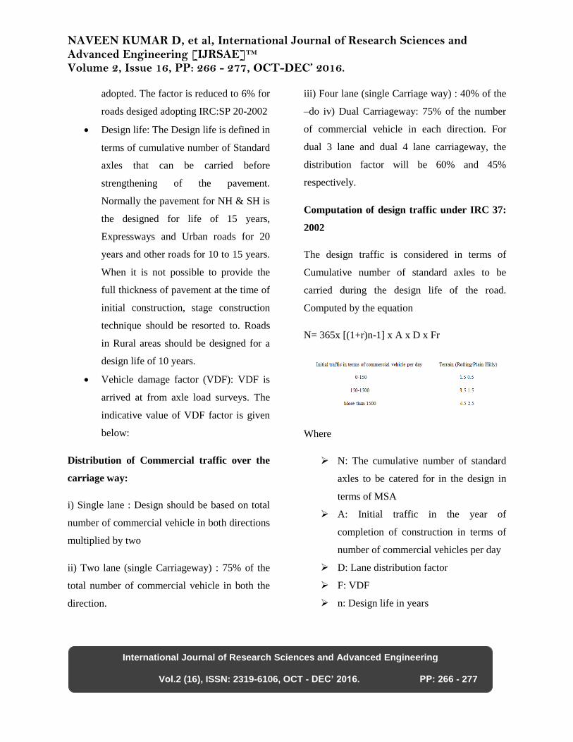
Computation of design traffic under IRC 37:
2002
The design traffic is considered in terms of
Cumulative number of standard axles to be
carried during the design life of the road.
Computed by the equation
N= 365x [(1+r)n-1] x A x D x Fr
Where
N: The cumulative number of standard
axles to be catered for in the design in
terms of MSA
A: Initial traffic in the year of
completion of construction in terms of
number of commercial vehicles per day
D: Lane distribution factor
F: VDF
n: Design life in years

NAVEEN KUMAR D, et al, International Journal of Research Sciences and Advanced Engineering [IJRSAE]TM Volume 2, Issue 16, PP: 266 - 277, OCT-DEC’ 2016.
International Journal of Research Sciences and Advanced Engineering
Vol.2 (16), ISSN: 2319-6106, OCT - DEC’ 2016. PP: 266 - 277
r : Annual growth rate of commercial
vehicles (for 7.5% annual growth rate
r=0.075)
The traffic in the year of completion is estimated
using the following formula:
A= P (1+r) x
Where
P = Number of Commercial vehicle as per last
count
x = Number of years between the last count and
the year of completion of construction
Computation of design traffic under SP 20:2002
The traffic for design life is computed as –
Number of commercial vehicles per day for
design A = P(1+r)n+x
Where
r= Annual growth rate of commercial vehicle
(i.e 6%)
P, x & n = as above
Bridge:
Bridge is a structure having a total length of
above between the inner faces of the dirt walls
for carrying traffic on road or railway. The
bridges shall be classified as minor bridge and
major bridge.
Minor bridge – Bridge having a total length up
to 60 meters. Clause 101.1 of IRC 5:1998
Major bridge – Bridge having a total length
above 60 meters.
The bridges are designed and constructed
adopting the following IRC specifications.
•IRC 5:1998 Standard specification and code of
practice for road bridges- Section I general
features of design
•IRC 6:1966 Standard specification and code of
practice for road bridges – Section II load and
stress
•IRC 21:1987 Standard specification and code of
practice for road bridges- Section III cement
concrete
•IRC 40 : 1995 Standard specification and code
of practice for road bridges- Section IV (bricks,
stones and masonry)
•IRC 22:1986 Standard specification and code of
practice for road bridges- Section VI composite
construction
•IRC 78:1983 Standard specification and code of
practice for road bridges- Section VII formation
and sub structure
•IRC 83:1987 Standard specification and code of
practice for road bridges- Section IX bearings
•IRC SP:20 2002 Rural Road Manual
•IRC SP 13:2001 Guideline for the design of
small bridges and culvert
Component of Bridge
NAVEEN KUMAR D, et al, International Journal of Research Sciences and Advanced Engineering [IJRSAE]TM Volume 2, Issue 16, PP: 266 - 277, OCT-DEC’ 2016.
International Journal of Research Sciences and Advanced Engineering
Vol.2 (16), ISSN: 2319-6106, OCT - DEC’ 2016. PP: 266 - 277
The component of the bridge is broadly grouped
into
i) Foundation
ii) Substructure
iii) Superstructure
The foundations are different type viz., open
foundation, well foundation, raft foundation and
pile foundation. The substructure is the portion
of the bridge structure such as pier and
abutments above the foundation unit and
supporting the superstructure. It shall also
include returns and wing walls but exclude
bearings. Superstructure is the portion of bridge
structure above the substructure level viz., deck
slab/beam, hand rail, foot path etc.
IMAGE OF BRIDGE SHOWING VARIOUS
COMPONENTS OF BRIDGE:
1. Deck
2. Girder
3. Bearing units
4. Pedestals
5. Pile cap
6. Pile
7. Live load
Terminology:
Clearance: Is the shortest distance between the
boundaries at a specified Position of a bridge.
Free Board: Free board at any point is the
difference between the highest flood level after
allowing for afflux if any, and the formation
level of road embankment on the approaches or
top level of guide bunds at that point. Free
Board for high-level bridge shall in no case be
less than 600 mm
Linear Water way: is the width of waterway
between the extreme edge of water surface at the
highest flood level measured at right angles to
the abutment faces.
Effective Linear Water way: is the total width of
the waterway of the bridge at HFL minus the
effective width of obstruction.
Afflux: The rise in flood level of the river
immediately on the up steam of the bridge as a
result of obstruction to the natural flow caused
by the construction of bridge and its approaches.
Scour Depth: In natural stream, the scouring
action of the current is not uniform all along the
bed width particularly at the bends and also
round obstructions to the flow eg. The piers of
bridges there is deeper scour than normal. The
assessment of the scour depth is relevant for the
design of bridge foundations and protective
works. Whenever possible such assessment
should be based on data made available from
actual Sounding taken at the proposed bridge
site or in its vicinity. Such soundings are being
taken during immediately after a flood before
the scour holes have had time to silt up
appreciably. Necessary allowance shall be made
in the observed scour depth for increased depth
for various reasons.
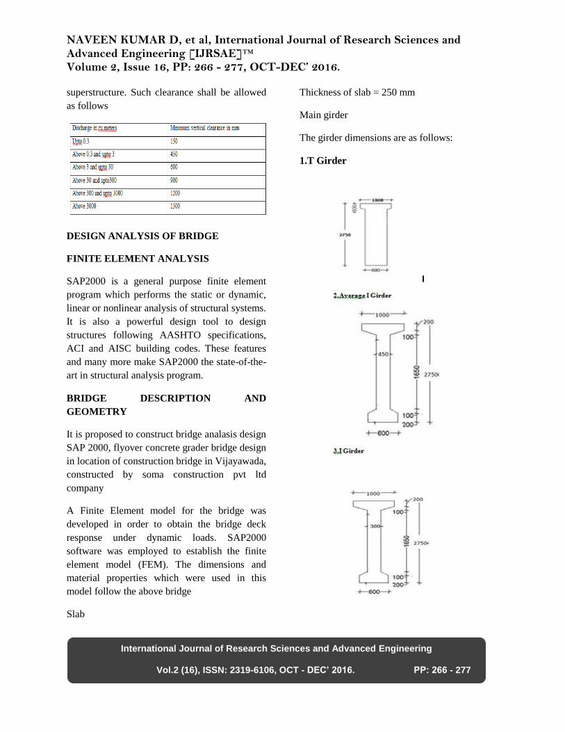
Vertical clearance: Adequate vertical clearance
shall be provided in case of all high level bridges
which is usually the height from the designed
HFL with afflux to the lowest point of the bridge
NAVEEN KUMAR D, et al, International Journal of Research Sciences and Advanced Engineering [IJRSAE]TM Volume 2, Issue 16, PP: 266 - 277, OCT-DEC’ 2016.
International Journal of Research Sciences and Advanced Engineering
Vol.2 (16), ISSN: 2319-6106, OCT - DEC’ 2016. PP: 266 - 277
superstructure. Such clearance shall be allowed
as follows
DESIGN ANALYSIS OF BRIDGE
FINITE ELEMENT ANALYSIS
SAP2000 is a general purpose finite element
program which performs the static or dynamic,
linear or nonlinear analysis of structural systems.
It is also a powerful design tool to design
structures following AASHTO specifications,
ACI and AISC building codes. These features
and many more make SAP2000 the state-of-the-
art in structural analysis program.
BRIDGE DESCRIPTION AND
GEOMETRY
It is proposed to construct bridge analasis design
SAP 2000, flyover concrete grader bridge design
in location of construction bridge in Vijayawada,
constructed by soma construction pvt ltd
company
A Finite Element model for the bridge was
developed in order to obtain the bridge deck
response under dynamic loads. SAP2000
software was employed to establish the finite
element model (FEM). The dimensions and
material properties which were used in this
model follow the above bridge
Slab
Thickness of slab = 250 mm
Main girder
The girder dimensions are as follows:
1.T Girder
NAVEEN KUMAR D, et al, International Journal of Research Sciences and Advanced Engineering [IJRSAE]TM Volume 2, Issue 16, PP: 266 - 277, OCT-DEC’ 2016.
International Journal of Research Sciences and Advanced Engineering
Vol.2 (16), ISSN: 2319-6106, OCT - DEC’ 2016. PP: 266 - 277
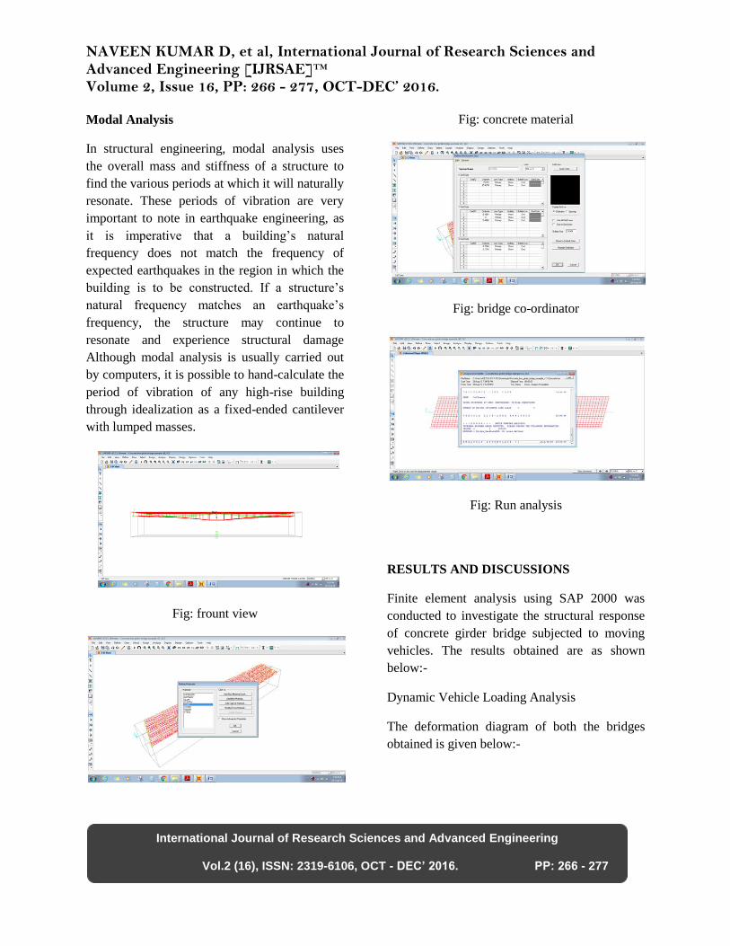
Modal Analysis
In structural engineering, modal analysis uses
the overall mass and stiffness of a structure to
find the various periods at which it will naturally
resonate. These periods of vibration are very
important to note in earthquake engineering, as
it is imperative that a building’s natural
frequency does not match the frequency of
expected earthquakes in the region in which the
building is to be constructed. If a structure’s
natural frequency matches an earthquake’s
frequency, the structure may continue to
resonate and experience structural damage
Although modal analysis is usually carried out
by computers, it is possible to hand-calculate the
period of vibration of any high-rise building
through idealization as a fixed-ended cantilever
with lumped masses.
Fig: frount view
Fig: concrete material
Fig: bridge co-ordinator
Fig: Run analysis
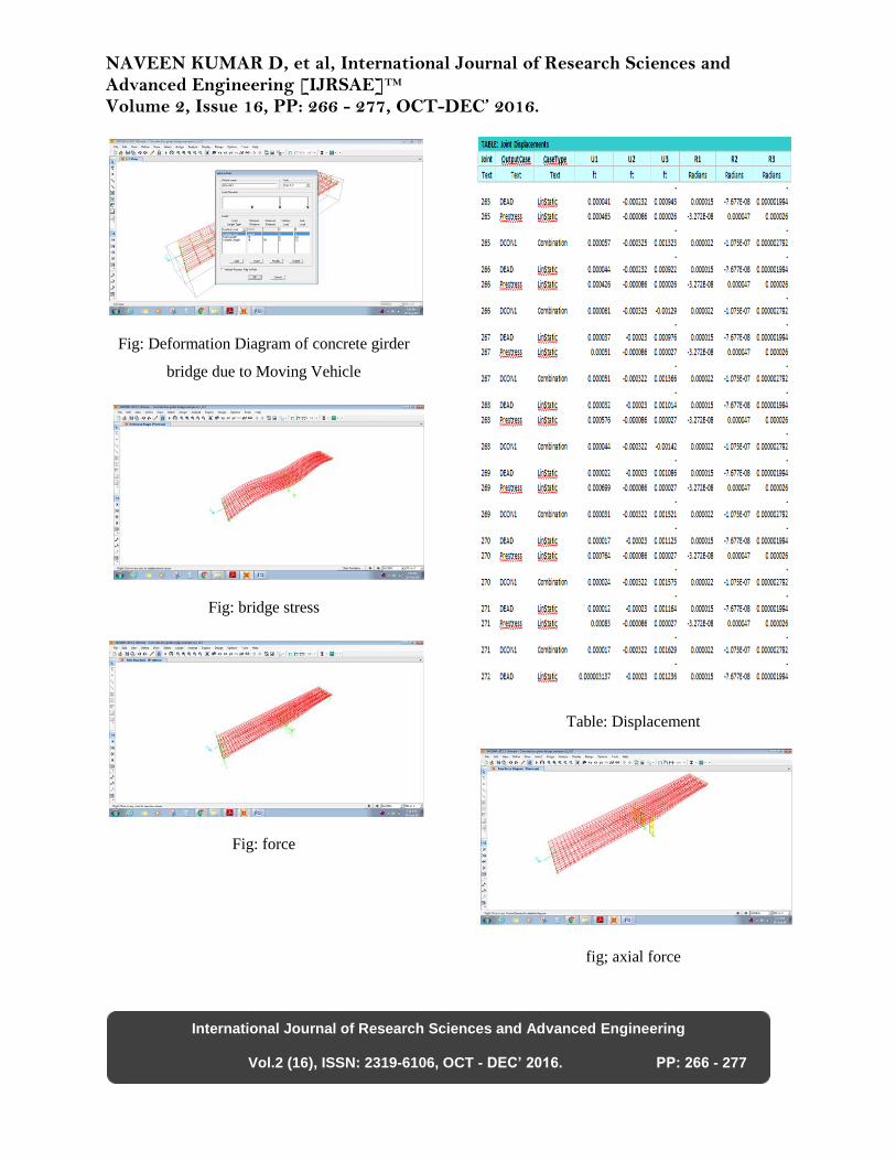
RESULTS AND DISCUSSIONS
Finite element analysis using SAP 2000 was
conducted to investigate the structural response
of concrete girder bridge subjected to moving
vehicles. The results obtained are as shown
below:-
Dynamic Vehicle Loading Analysis
The deformation diagram of both the bridges
obtained is given below:-
NAVEEN KUMAR D, et al, International Journal of Research Sciences and Advanced Engineering [IJRSAE]TM Volume 2, Issue 16, PP: 266 - 277, OCT-DEC’ 2016.
International Journal of Research Sciences and Advanced Engineering
Vol.2 (16), ISSN: 2319-6106, OCT - DEC’ 2016. PP: 266 - 277
Fig: Deformation Diagram of concrete girder
bridge due to Moving Vehicle
Fig: bridge stress
Fig: force
Table: Displacement
fig; axial force

NAVEEN KUMAR D, et al, International Journal of Research Sciences and Advanced Engineering [IJRSAE]TM Volume 2, Issue 16, PP: 266 - 277, OCT-DEC’ 2016.
International Journal of Research Sciences and Advanced Engineering
Vol.2 (16), ISSN: 2319-6106, OCT - DEC’ 2016. PP: 266 - 277
Fig:Bridge analysis
Table: base reaction
SUMMARY AND CONCLUSIONS
In this paper, a comparison of dynamic response
of concrete girder bridge and suspension cable
brige was studied. For that the proposed bridge
structure was modeled and analyzed as concrete
girder Bridge using software SAP 2000.
From the bending moment values and
deflections obtained, the suspension cable brige
provides lesser moments and high deflections as
compared to that of concrete girder bridge for
the same vehicle loading condition.
The values of the frequencies of concrete
bridges are generally larger than those of
continuous concrete girder bridges.
Finally, it is inferred that continuous concrete
girder bridge has the advantage of good stability
for heavy vehicles and economical in
comparison with the concrete bridge.
REFERENCES
•Iman Mohseni, A. R. Khalim, Ehsan Nikbakht,
”Effectiveness of Skewness on Dynamic Impact
Factor of Concrete Multicell Box-Girder
Bridges Subjected to Truck Loads” Arabian
Journal for Science and Engineering, Vol 39,
2014
•Jones, Marvin ,Chu, Kuang Han, ”Dynamic
analysis of a box girder bridge”, IABSE
publications, 2014
•K.A. Hossain and K.M. Amanat,”Dynamic
amplification of transverse stress at the root of
cantilever slab of RC box girder bridges”,
IABSEJSCE Joint Conference on Advances in
Bridge Engineering-II August 8-10, 2010
•Magdy Samaan; John B. Kennedy, F.ASCE;
and Khaled Sennah,”Dynamic Analysis of
Curved Continuous Multiple-Box Girder
Bridges ”, Journal of Bridge Eng Vol 12(2), pg
184193, 2009
• Md. Robiul Awall, Toshiro Hayashikawa,
Takashi Matsumoto, Xingwen He,”Parametric
Study on Bridge-vehicle Interaction Dynamics
of Horizontally Curved Twin I-girder Bridge”,
Proceedings of the 8th International Conference
on Structural Dynamics, EURODYN 2011
•Mehrdad Bisadi, S.A. Osman and Shahrizan
Baharom,”Finite Element Analyses on Dynamic
Behavior of Railway Bridge Due To High Speed
Train”, Australian Journal of Basic and Applied
Sciences Vol 6 , 2012

NAVEEN KUMAR D, et al, International Journal of Research Sciences and Advanced Engineering [IJRSAE]TM Volume 2, Issue 16, PP: 266 - 277, OCT-DEC’ 2016.
International Journal of Research Sciences and Advanced Engineering
Vol.2 (16), ISSN: 2319-6106, OCT - DEC’ 2016. PP: 266 - 277
•Civil Engineering International Journals
(CEIJ),www.civilengjournals.com
The bridges are designed and constructed
adopting the following IRC specifications.
•IRC 5:1998 Standard specification and code of
practice for road bridges- Section I general
features of design
•IRC 6:1966 Standard specification and code of
practice for road bridges – Section
II load and stress
•IRC 21:1987 Standard specification and code of
practice for road bridges- Section
III cement concrete
•IRC 40 : 1995 Standard specification and code
of practice for road bridges- Section
IV (bricks, stones and masonry)
•IRC 22:1986 Standard specification and code of
practice for road bridges- Section
VI composite construction
•IRC 78:1983 Standard specification and code of
practice for road bridges- Section
VII formation and sub structure
•IRC 83:1987 Standard specification and code of
practice for road bridges- Section
IX bearings
•IRC SP:20 2002 Rural Road Manual
•IRC SP 13:2001 Guideline for the design of
small bridges and culvert