Embed Size (px)
Citation preview

http://www.iaeme.com/IJMET/index.asp 175 [email protected]
International Journal of Mechanical Engineering and Technology (IJMET) Volume 8, Issue 5, May 2017, pp. 175–185 Article ID: IJMET_08_05_019
Available online at http:// http://www.iaeme.com/ijmet/issues.asp?JType=IJMET&VType=8&IType=5
ISSN Print: 0976-6340 and ISSN Online: 0976-6359
© IAEME Publication Scopus Indexed
DESIGN AND ANALYSIS OF DIFFERENTIAL
GEAR BOX IN AUTOMOBILES
N. Siva Teja
Asst. Professor, Dept. of Mechanical Engineering,
K L University, Vaddeswaram, Andhra Pradesh
K. Dinesh Babu, M. Siva Nagendra, Ch. Phanideep, J. Sai Trinadh Dept. of Mechanical Engineering, K L University,
Vaddeswaram, Andhra Pradesh,
ABSTRACT
The main objective of this paper is to perform mechanical design of differential gear
box and analysis of gears in gear box. We have taken grey cast iron and aluminium alloy
materials for conducting the analysis. Presently used materials for gears and gears shafts
is Cast Iron, Cast Steel. So, in this paper we are checking as the aluminum can be the other
material for the differential gear box for light utility vehicles so, we can reduce the weight.
Key words: Differential Gear Box, Structural Analysis, Design and Structural Analysis of
Differential Gear Box
Cite this Article: N. Siva Teja, K. Dinesh Babu, M. Siva Nagendra, Ch. Phanideep, J. Sai
Trinadh, Design and Analysis of Differential Gear Box In Automobiles, International
Journal of Mechanical Engineering and Technology, 8(5), 2017, pp. 175-185.
http:// http://www.iaeme.com/ijmet/issues.asp?JType=IJMET&VType=8&IType=5
1. INTRODUCTION
A differential is a gear train with three shafts that has the property that the angular velocity of one
shaft is the average of the angular velocities of the others, or a fixed multiple of that average. A
gear box provides speed and torque conversions from a rotating power source to another device
using gear ratios. In automobiles and other wheeled vehicles, the differential allows the outer drive
wheel to rotate faster than the inner drive wheel during a turn. This is necessary when the vehicle
turns, making the wheel that is traveling around the outside of the turning curve roll farther and
faster than the other. The average of the rotational speed of the two driving wheels equals the input
rotational speed of the drive shaft. An increase in the speed of one wheel is balanced by a decrease
in the speed of the other. When used in this way, a differential couples the input shaft (or prop
shaft) to the pinion, which in turn runs on the ring gear of the differential. This also works as

Design and Analysis of Differential Gear Box In Automobiles
http://www.iaeme.com/IJMET/index.asp 176 [email protected]
reduction gearing. On rear wheel drive vehicles, the differential may connect to half-shafts inside
an axle housing, or drive shafts that connect to the rear driving wheels. Front wheel drive vehicles
tend to have the pinion on the end of the main-shaft of the gearbox and the differential is enclosed
in the same housing as the gearbox. There are individual drive-shafts to each wheel.
2. OBJECTIVES OF PRESENT WORK
We are creating the frictional contact between two mating gears. And we are doing the structural
analysis on gear box by providing the torque to the sun gear in the differential gear box.
3. MODELING AND ANALYSIS
3.1. Modeling details
To determine the structural analysis on the differential gear box. First, we have to create a model
of differential gear box in modeling software’s. We have the assembly of differential gear box in
SOLIDWORKS.
3.2. Build Geometry
Construct a three-dimensional representation of the bevel gears in SOLIDWORKS. The assembly
consists of 2 side gears, 2 ring gears and on sun gear. After doing the assembly in solidworks. Save
the file in. IGES format continuing the further work in ANSYS Mechanical.
Figure 3.1.1 FinalAssembly of differential gear box

N. Siva Teja, K. Dinesh Babu, M. Siva Nagendra, Ch. Phanideep, J. Sai Trinadh
http://www.iaeme.com/IJMET/index.asp 177 [email protected]
4. DESIGN OF DIFFERENTIAL GEAR BOX
Figure 4.1.1 This figure represents the modeling of first side gear in solidworks. It is creaeted by drawing
the bevel gear profile from prerequisites and removing the faces of bevel gear tooth for 45 deg mating of
other gears for assembly.and adding an extruded stub axles rods to it.
Figure 4.1.2 It is the second bevel side gear.This figure represents the modeling of second side gear in
solidworks. It is creaeted by drawing the bevel gear profile from prerequisites and removing the faces of
bevel gear tooth for 45 deg mating of other gears for assembly.and adding an extrude stub axles to it.
Figure 4.1.3 This figure represents the modeling of ring gear in solidworks. It is creaeted by drawing the
bevel gear profile from prerequisites and removing the faces of bevel gear tooth for 45 deg mating of
other gears for assembly.and adding an xtrude stub axles to it. The ring rotates while the vehicle is taking
a turn. It rotates in it’s own axis.

Design and Analysis of Differential Gear Box In Automobiles
http://www.iaeme.com/IJMET/index.asp 178 [email protected]
Figure 4.1.4 This figure represents the modeling of sun gear in solidworks. It is creaeted by drawing the
bevel gear profile from prerequisites and removing the faces of bevel gear tooth for 45 deg mating of
other gears for assembly.and adding an extruded sun gear plates for the fixing of two side and two ring
gears.The sun gears carry the torque that is coming from the engine .
5. ANALYSIS OF DIFFERENTIAL GEAR BOX
5.1. Engineering Data
We have used two different materials like grey cast iron and aluminium alloy for the analysis of
this product.
Table:5.1.1 It Shows The Material Properties of grey cast iron.
Density 7200 kg m^-3
Coefficient of Thermal Expansion 1.1e-005 C^-1
Specific Heat 447 J kg^-1 C^-1
Thermal Conductivity 52 W m^-1 C^-1
Resistivity 9.6e-008-ohm m
Young's Modulus Pa 1.1e+011
Poisson's Ratio 0.28
Tensile Ultimate Strength 2.4e+008
Compressive Ultimate Strength 8.2e+008
Table 5.1.2: It Shows The Material Properties of Aluminium Alloy.
Density 2770 kg m^-3 Coefficient of Thermal Expansion 2.3e-005 C^-1
Specific Heat 875 J kg^-1 C^-1 Young's Modulus Pa 7.1e+010 Poisson's Ratio 0.33 Resistivity 3.63e-008-ohm m Thermal Conductivity 114 W m^-1 C^-1 Tensile Yield Strength 2.8e+008 Tensile Ultimate Strength 3.1e+008
N. Siva Teja, K. Dinesh Babu, M. Siva Nagendra, Ch. Phanideep, J. Sai Trinadh
http://www.iaeme.com/IJMET/index.asp 179 [email protected]
5.2. Frictional Contacts
Figure 5.2.1 It shows the frictional coefficient between the mating gears as 0.2. for the frictional or
rubbing contact between to test for the thermal conditions.
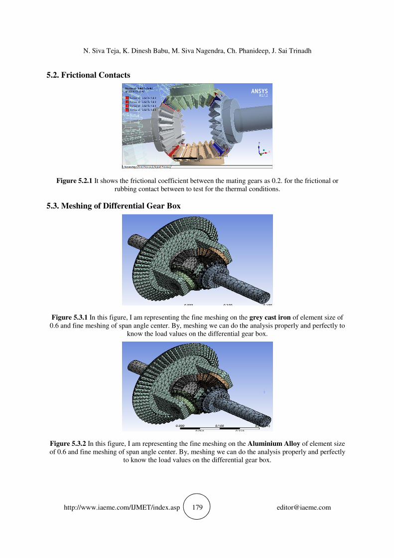
5.3. Meshing of Differential Gear Box
Figure 5.3.1 In this figure, I am representing the fine meshing on the grey cast iron of element size of
0.6 and fine meshing of span angle center. By, meshing we can do the analysis properly and perfectly to
know the load values on the differential gear box.
Figure 5.3.2 In this figure, I am representing the fine meshing on the Aluminium Alloy of element size
of 0.6 and fine meshing of span angle center. By, meshing we can do the analysis properly and perfectly
to know the load values on the differential gear box.

Design and Analysis of Differential Gear Box In Automobiles
http://www.iaeme.com/IJMET/index.asp 180 [email protected]
5.4. Torque acting on the Differential Gear Box
Figure 5.4.1 This figure shows the combined image of all torques applied on the differential gear box the
torques applied are 190, 235, 320 (N-m).
5.5. Fixed Support for Differential Gear Box
Figure 5.5.1: In this figure, we are representing the fixed supports because while doing the structural
analysis we can’t do it without giving the fixed supports so we have the fixed supports to the sun gear
hands because it doesn’t imply any forces on the analysis of the paper.

N. Siva Teja, K. Dinesh Babu, M. Siva Nagendra, Ch. Phanideep, J. Sai Trinadh
http://www.iaeme.com/IJMET/index.asp 181 [email protected]
6. EXPERIMENTAL RESULTS
Total Deformation of Grey Cast Iron
Figure 6.1 It shows the Total Deformation stress values of the differential gear box at different torques
at 190, 235, 320 (N-m) on Grey Cast Iron
Von-Mises Stress of Differential Gear Box:
Figure 6.2 It shows the Von-Mises stress values of the differential gear box at different torques at 190,
235, 320 (N-m) on Grey Cast Iron.

Design and Analysis of Differential Gear Box In Automobiles
http://www.iaeme.com/IJMET/index.asp 182 [email protected]
Total Deformation of Aluminium Alloy
Figure 6.3 It shows the Total Deformation stress values of the differential gear box at different torques
at 190, 235, 320 (N-m) on Aluminium Alloy.
Von-Mises Stress of Differential Gear Box
Figure 6.4 It shows the Von-Mises stress values of the differential gear box at different torques at 190,
235, 320 (N-m) on Aluminium Alloy.

N. Siva Teja, K. Dinesh Babu, M. Siva Nagendra, Ch. Phanideep, J. Sai Trinadh
http://www.iaeme.com/IJMET/index.asp 183 [email protected]
7. RESULTS & DISCUSSIONS
7.1. Total Deformation and Von-Mises Stresses of Grey Cast Iron
S.no Torque (N-m) Total Deformation
(mm)
Von-Mises Stresses
(MPa)
1 190 2.6424*e^-3 20.6847
2 235 2.6415*e^-3 32.681
3 320 2.6399*e^-3 43.716
7.2. Total Deformation and Von-Mises Stresses of Aluminium Alloy
S.no Torque (N-m) Total Deformation
(mm)
Von-Mises Stresses
(MPa)
1 190 1.5791*e^-3 25.029
2 235 1.578*e^-3 30.773
3 320 1.646*e^-3 44.18
Graphs
For Grey Cast Iron
25
30
35
40
45
190 235 320
Von-Mises Stress
Von-Mises Stress
0.002635
0.002637
0.002639
0.002641
190 235 320
Total Deformation
Total Deformation

Design and Analysis of Differential Gear Box In Automobiles
http://www.iaeme.com/IJMET/index.asp 184 [email protected]
For Aluminium Alloy
7. CONCLUSION
In this project, we have taken the frictional contact between the mating gears as 0.2 to see does the
frictional contact the effect the load or not. From, the above results and graphs we found that both
grey cast iron and aluminium alloy are preferable for performing the application of differential
gearbox in automobiles. But, when it comes to weight for light utility vehicles Aluminium Alloy
is preferred.
REFERENCES
[1] N. Vijay Babu, Ch. Sekhar, Design and Analysis of Differential Gear Box Used In Heavy
Vehicles, ishitv, 20-21 nov, 2015. Vol.2, No.1.
[2] C. Veeranjaneyulu, U. Hari Babu, Design and Structural Analysis of Differential gear Box At
Different Loads”, ijaer, 2002, ongole, Andhra Pradesh.
[3] Sumair Sunny, Siddhesh Ozarkar, Sunny Pawar, Design of An Automotive Differential With
Reduction Ratio Greater Than 6, IJRET, 2006.
[4] S.H. Gawande, S.V. Khandagale, V.T. Jadhav, V.D. Patil, D.J. Thorat, Design, Manufacturing
And Analysis Of Differential Crown Gear and Pinion For MFWD Axle, IOSR, Pune India
[5] R. Morselli, Detailed and Reduced Models of Passive and Active Limited Slip Car
Differentials, August 2006.
[6] G.M. Mitra, Hand Book of Gear Design, Tata McGraw Hill, New Delhi.
[7] Daniel Das.A, Seenivasan.S, Karthick.S, Structural Analysis of Gear Ox, JIET, April 2013,
Vol.2 issue 2.
[8] J.O. Nordiana, S.O. Ogbeide, N.N. Ehigiamusoe and F.I. Anyasi, Computer Aided Design of
A Spur Gear, Journal of Engineering and Applied Sciences, 2003.
0
20
40
60
190 235 320
Von-Mises Stress
Von-Mises Stress
0.0015
0.00155
0.0016
0.00165
0.0017
190 235 320
Total Deformation
Total Deformation

N. Siva Teja, K. Dinesh Babu, M. Siva Nagendra, Ch. Phanideep, J. Sai Trinadh
http://www.iaeme.com/IJMET/index.asp 185 [email protected]
[9] Zeping Wei, Stresses and Deformations in Involute Spur Gears by Finite element Method, M.S,
Thesis, College of Graduate Studies and research, University of Saskatchewan, 2004.
[10] K. Sunil Kumar, Dr. Sumathy Muniamuthu, S. Arun and A. Mohan, Identification
Experimental Analysis of Noise and Vibration Reduction in Windmill Gear Box for 5MW
Wind Turbine. International Journal of Mechanical Engineering and Technology, 7(6), 2016,
pp. 76–85.
[11] P.Vinay, Ch. Venkata Satya Sri Vamsi, M.Hemanth, A.Saiteja, Mohammad Abid Ali and P.
Ashok Kumar, Design and Simulation of Mems Based Accelerometer For Crash Detection and
Air Bags Deployment In Automobiles, International Journal of Mechanical Engineering and
Technology, 8(4), 2017, pp. 424-434
[12] Darle W. Dudley, Hand Book of Practial Gear Design, 1954.
[13] Alce Strokes, High Performance of Gear Design, 1970.