Embed Size (px)
Citation preview

Volume 6, Issue 2 JULY 2017
IJRAET
DESIGN AND ANALYSIS OF GAS TURBINE BLADE
1 Kottha Srinivas, 2 Mr. M.Prasad 1 PG Scholar, Department of MECH, Methodist COLLEGE of Engineering & Technology.
Abids, Hyderabad – 500 001.
2 Assistant Professor, Department of MECH, Methodist COLLEGE of Engineering & Technology.
Abids, Hyderabad – 500 001.
Abstract
A gas turbine used in power generation by converting
kinematic energy into mechanical energy by rotors.
The rotors has to withstand high temperatures,
pressure, stresses and strains during compression and
expansion in turbine and it has to increase thermal
efficiency. The life of the blade is also important by
avoiding fatigue. Solidworks software is used to
model it. Meshing, analysis is performed by Ansys
14.5 software. Rotors cooling methods are also
analyzed to improve convection and decrease
temperatures on blades. Deformations are analyzed
by static structural analysis. Thermal stresses and
strains results by software are compared for different
materials. This analysis is done to introduce new
innovated materials into real-time application on
existing or new products to increase efficiency and
life.Structural load like Pressure analysis is done at
required areas to choose a best material. Vibrational
frequency in turbine are also estimated by modal
analysis.
Fig: Gas turbine blade with rotor
1. Introduction:
Gas turbines are used for power generation. Today,
gas turbines are one of the most widely-used power
generating technologies. Gas turbines are a type of
internal combustion (IC) engine in which burning of
an air-fuel mixture produces hot gases that spin a
turbine to produce power. It is the production of hot
gas during fuel combustion, not the fuel itself that the
gives gas turbines the name. Gas turbines can utilize
a variety of fuels, including natural gas, fuel oils, and
synthetic fuels. Combustion occurs continuously in
gas turbines, as opposed to reciprocating IC engines,
in which combustion occurs intermittently.
Fig: Gas turbine rotor blade
2. How does a gas turbine works:
Gas turbines are comprised of three primary sections
mounted on the same shaft: the compressor, the
combustion chamber (or combustor) and the turbine.
The compressor can be either axial flow or
Volume 6, Issue 2 JULY 2017
IJRAET
centrifugal flow. Axial flow compressors are more
common in power generation because they have
higher flow rates and efficiencies. Axial flow
compressors are comprised of multiple stages of
rotating and stationary blades (or stators) through
which air is drawn in parallel to the axis of rotation
and incrementally compressed as it passes through
each stage. The acceleration of the air through the
rotating blades and diffusion by the stators increases
the pressure and reduces the volume of the air.
Although no heat is added, the compression of the air
also causes the temperature to increase.
The compressed air is mixed with fuel injected
through nozzles. The fuel and compressed air can be
pre-mixed or the compressed air can be introduced
directly into the combustor. The fuel-air mixture
ignites under constant pressure conditions and the hot
combustion products (gases) are directed through the
turbine where it expands rapidly and imparts rotation
to the shaft. The turbine is also comprised of stages,
each with a row of stationary blades (or nozzles) to
direct the expanding gases followed by a row of
moving blades. The rotation of the shaft drives the
compressor to draw in and compress more air to
sustain continuous combustion. The remaining shaft
power is used to drive a generator which produces
electricity. Approximately 55 to 65 percent of the
power produced by the turbine is used to drive the
compressor. To optimize the transfer of kinetic
energy from the combustion gases to shaft rotation,
gas turbines can have multiple compressor and
turbine stages.
Because the compressor must reach a certain speed
before the combustion process is continuous or self-
sustaining – initial momentum is imparted to the
turbine rotor from an external motor, static frequency
converter, or the generator itself. The compressor
must be smoothly accelerated and reach firing speed
before fuel can be introduced and ignition can occur.
Turbine speeds vary widely by manufacturer and
design, ranging from 2,000 revolutions per minute
(rpm) to 10,000 rpm. Initial ignition occurs from one
or more spark plugs (depending on combustor
design). Once the turbine reaches self-sustaining
speed – above 50% of full speed – the power output
is enough to drive the compressor, combustion is
continuous, and the starter system can be disengaged.
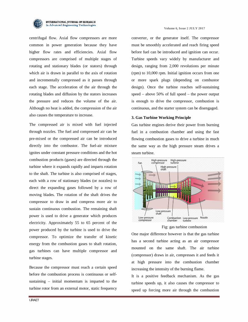
3. Gas Turbine Working Principle
Gas turbine engines derive their power from burning
fuel in a combustion chamber and using the fast
flowing combustion gases to drive a turbine in much
the same way as the high pressure steam drives a
steam turbine.
Fig: gas turbine combustion
One major difference however is that the gas turbine
has a second turbine acting as an air compressor
mounted on the same shaft. The air turbine
(compressor) draws in air, compresses it and feeds it
at high pressure into the combustion chamber
increasing the intensity of the burning flame.
It is a positive feedback mechanism. As the gas
turbine speeds up, it also causes the compressor to
speed up forcing more air through the combustion

Volume 6, Issue 2 JULY 2017
IJRAET
chamber which in turn increases the burn rate of the
fuel sending more high pressure hot gases into the
gas turbine increasing its speed even more.
Uncontrolled runaway is prevented by controls on the
fuel supply line which limit the amount of fuel fed to
the turbine thus limiting its speed.
Fig: Gas turbine
The thermodynamic process used by the gas turbine
is known as the Brayton cycle. Analogous to
the Carnot cycle in which the efficiency is
maximized by increasing the temperature difference
of the working fluid between the input and output of
the machine, the Brayton cycle efficiency is
maximized by increasing the pressure difference
across the machine. The gas turbine is comprised of
three main components: a compressor, a combustor,
and a turbine. The working fluid, air, is compressed
in the compressor (adiabatic compression - no heat
gain or loss), then mixed with fuel and burned by the
combustor under constant pressure conditions in the
combustion chamber (constant pressure heat
addition). The resulting hot gas expands through the
turbine to perform work (adiabatic expansion). Much
of the power produced in the turbine is used to run
the compressor and the rest is available to run
auxiliary equipment and do useful work. The system
is an open system because the air is not reused so that
the fourth step in the cycle, cooling the working fluid,
is omitted.
Gas turbines have a very high power to weight ratio
and are lighter and smaller than internal combustion
engines of the same power. Though they are
mechanically simpler than reciprocating engines,
their characteristics of high speed and high
temperature operation require high precision
components and exotic materials making them more
expensive to manufacture.
4. Solidworks
Solid Works is mechanical design automation
software that takes advantage of the familiar
Microsoft Windows graphical user interface.
It is an easy-to-learn tool which makes it possible for
mechanical designers to quickly sketch ideas,
experiment with features and dimensions, and
produce models and detailed drawings.
Introduction to Solidworks:
Solidworks mechanical design automation software is
a feature-based, parametric solid modeling design
tool which advantage of the easy to learn windows TM
graphical user interface. We can create fully associate
3-D solid models with or without while utilizing
automatic or user defined relations to capture design
intent.
Parameters refer to constraints whose values
determine the shape or geometry of the model or
assembly. Parameters can be either numeric
parameters, such as line lengths or circle diameters,
or geometric parameters, such as tangent, parallel,
concentric, horizontal or vertical, etc. Numeric
parameters can be associated with each other through
the use of relations, which allow them to capture
design intent.
Volume 6, Issue 2 JULY 2017
IJRAET
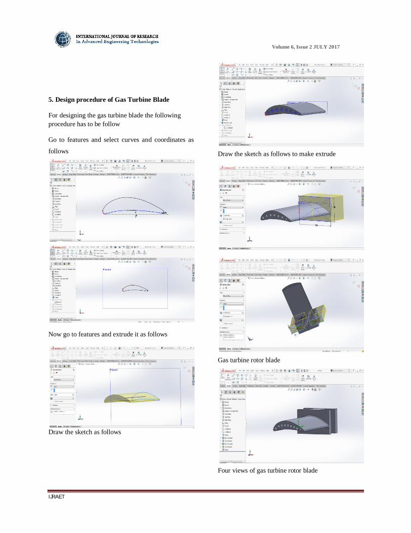
5. Design procedure of Gas Turbine Blade
For designing the gas turbine blade the following procedure has to be follow
Go to features and select curves and coordinates as
follows
Now go to features and extrude it as follows
Draw the sketch as follows
Draw the sketch as follows to make extrude
Gas turbine rotor blade
Four views of gas turbine rotor blade

Volume 6, Issue 2 JULY 2017
IJRAET
6. Finite Element Analysis:
Introduction:
Finite Element Analysis (FEA) is a computer-based
numerical technique for calculating the strength and
behaviour of engineering structures. It can be used to
calculate deflection, stress, vibration, buckling
behaviour and many other phenomena. It also can be
used to analyze either small or largescale deflection
under loading or applied displacement. It uses a
numerical technique called the finite element method
(FEM).
Basic Concepts of Analysis:
Meshing:
The software uses the Finite Element Method (FEM).
FEM is a numerical technique for analyzing
engineering designs. FEM is accepted as the standard
analysis method due to its generality and suitability
for computer implementation. FEM divides the
model into many small pieces of simple shapes called
elements effectively replacing a complex problem by
many simple problems that need to be solved
simultaneously.
Material data:
7. Structural analysis on Gas Turbine
Fixed support
Pressure (1 MPA)
Meshing
Size: fine

Volume 6, Issue 2 JULY 2017
IJRAET
Material: Stainless Steel
Maximum stress
Total deformation
Maximum strain
Material: Titanium alloy
Maximum stress
Total deformation
Maximum strain
Material: Inconel (Nickel 625 Alloys)
Maximum stress
Volume 6, Issue 2 JULY 2017
IJRAET
Total deformation
Maximum strain
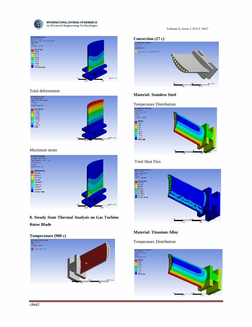
8. Steady State Thermal Analysis on Gas Turbine
Rotor Blade
Temperature (900 c)
Convection (27 c)
Material: Stainless Steel
Temperature Distribution
Total Heat Flux
Material: Titanium Alloy
Temperature Distribution

Volume 6, Issue 2 JULY 2017
IJRAET
Total Heat Flux
Material: Inconel (Nickel 625 Alloys)
Temperature Distribution
Total Heat Flux
10. Dynamic (Modal) Analysis
Material: Stainless Steel
Mode-1
Mode-2
Mode-3
Mode-4
11. Results

Volume 6, Issue 2 JULY 2017
IJRAET
Experimental Results
MODAL Analysis Results
12. Conclusion
Modeling and analysis on gas turbine rotor blade is
done.
Static structural analysis and thermal analysis are
done.
In static structural analysis 1 mpa pressure is
applied by assigning four various materials such as
stainless steel, titanium alloy, and inconel
Maximum stress, strain & deformations are
obtained titanium is showing least stress values
compared to stainless steel and inconel
Inconel (Nickel 625 Alloy) showing least strain
value as well as least deformation value compare to
titanium & stainless steel.
In steady state thermal analysis maximum
temperature is given as 9000C and convection
through holes is 270C
Temperature distribution and total heat flux values
are studied and tabulated. Max heat dissipation that is
cooling is done by inconel materials followed by
stainless steel.
Decreased failure rates by stress analysis and
thermal analysis.
References:
[1] Gowreesh, S., Sreenivasalu Reddy, N. and
Yogananda Murthy, NV. 2009. Convective Heat
Transfer Analysis of a Aero Gas Turbine Blade
Using Ansys, International Journal of Mechanics
and Solids. 4: 39-46.
[2] Facchini, B. and Stecco. S.S. 1999. Cooled
expansion in gas turbines: a comparison of analysis
methods, Energy Conversion and Management. 40:
1207-1224.
[3] Mohammad, H., Albeirutty., Abdullah, S.,
Alghamdi., Yousef, S. Najjar. 2004. Heat transfer
analysis for a multistage gas turbine using different
blade-cooling schemes, Applied Thermal
Engineering. 24: 563-577.
[4] Mahfoud, K. and George, B. 1997. Computational
study of turbine blade cooling by slot-injection of a
gas, Applied Thermal Engineering. 17: 1141-1149.
[5] Moyroud, F., Fransson, T. and Jacquet-Richardet,
G. 2002. A comparison of two finite element

Volume 6, Issue 2 JULY 2017
IJRAET
reduction techniques for mistuned bladed-disks,
Journal of Engineering for Gas Turbines and Power.
124: 942-953.
[6] Giovanni, C., Ambra, G., Lorenzo, B. and
Roberto, F. 2007 Advances in effusive cooling
techniques of gas turbines, Applied Thermal
Engineering. 27: 692-698.
[7] Cun-liang, L., Hui-ren, Z., Jiang-tao, B. and Du-
chun, X. 2010. Film cooling performance of
converging slot-hole rows on a gas turbine blade,
International Journal of Heat and Mass Transfer. 53:
5232-5241.
[8] Zhang, JJ.,Esat, II. and Shi, YH. 1999. Load
Analysis with Varying Mesh Stiffness, Computers
and Structures. 70: 273-280.
[9] Hildebrabd, FB. 1997. Introduction to Numerical
Analysis, McGraw-Hill, New York.
[10] MoussaviTorshizi, SE.,YadavarNikravesh, SM.
and Jahangiri, A. 2009. Failure analysis of gas
turbine generator cooling fan blades, Engineering
Failure Analysis. 16: 1686-1695.
[11] Cleeton, JPE., Kavanagh, RM. and Parks, GT.
2009. Blade cooling optimisation in humid-air and
steam-injected gas turbines, Applied Thermal
Engineering. 29: 3274-3283.
[12] Krishnamoorthy, C. 1994. Finite Element
Analysis Theory and Programming,Tata McGraw-
Hill, New Delhi.
[13] Martin, HC. and Carey, GF. 2006. Introduction
to the Finite Element Analysis,McGraw Hill
Publishing Co Ltd, New Delhi.