Embed Size (px)
Citation preview
Biomedical Statistics and Informatics 2017; 2(2): 49-53
http://www.sciencepublishinggroup.com/j/bsi
doi: 10.11648/j.bsi.20170202.12
Design and Analysis of Hexagon Microstrip Patch Sierpinski Carpet Antenna
T. Jayanthy, D. Rajeswari
ECE Department, Panimalar Institute of Technology, Chennai, India
Email address:
[email protected] (T. Jayanthy), [email protected] (D. Rajeswari)
To cite this article: T. Jayanthy, D. Rajeswari. Design and Analysis of Hexagon Microstrip Patch Sierpinski Carpet Antenna. Biomedical Statistics and
Informatics. Vol. 2, No. 2, 2017, pp. 49-53. doi: 10.11648/j.bsi.20170202.12
Received: January 11, 2017; Accepted: January 24, 2017; Published: February 21, 2017
Abstract: In the present paper a detailed study of a new compacted hexagon microstrip patch antenna using fractal ground
plane and shorting pin is presented. The design process starts by a simple hexagon patch antenna fed by a microstrip line and
simulated in the frequency range of 3.1GHz-10.8GHz. The fractal geometry used here is Sierpinski carpets method. Three
iterations have been done and the third iteration gives best performance. The miniaturization strategy is performed in two
stages. The first stage, a third order of the Sierpinski carpet is applied to the ground. Inserting a shorting pin linking the patch
to the ground constituted the second stage. Both the stages are analyzed and compared, Sierpinski carpet the gives best output.
The performances are analyzed in terms of return loss, directivity, gain, and radiation pattern.
Keywords: Fractal Antenna, Sierpinski Carpet, Array, Shorting Pin
1. Introduction
In military application system the performance of the
antenna requires large gain, wider bandwidth, low cost and
small size. The conventional microstrip antenna is not
sufficient to fulfill the above requirements. Hence the
researchers have doing some research work on some
innovative antenna to satisfy these parameters. Among them
Dr. Nathan Cohen found a different technology called fractal
antenna in 1995 and his research is used in commercial and
military applications.
These fractal antenna is a new antenna design which is
used in military as well as commercial applications which
provides more size reduction, wider bandwidth, compact
size, better input impedance, consistence performance over
huge frequency range, close packing of antennas, easy to
manufacture, reliable, high gain, multiband, low price and
instantaneous spectrum access. Conventional antenna
requires tuning and matching circuits these can be replaced
by a suitable antenna technology which has a unique feature
and this antenna is called Fractal antenna. In fractal antenna
the overall structure is comprised of a series of repetition of a
single geometry and where repetition is at different scale.
Fractal is a geometric shape that has the property of self-
similarity that is each part of the shape is a smaller version of
the original shape. The various shape of fractal antennas are
snail shells, leaves on a tree, pine cones, triangular, circular,
square etc. These structures are having a finite area but
infinite perimeter. They are often constructed via some sort
of iterative mathematical rule, that generates a fractal from a
simple object step by step.
Fractals have been used to design compact multiband
antennas and miniaturized filters. The various fractal
geometries are Minkowski, Sierpinski carpet, Sierpinski
Gasket, Hilbert curves, von Koch curves and so on. Fractal
geometries have two common properties, space-filling and
self-similarity different from Euclidean geometries. Fractal
curves are well known for their unique space-filling properties.
A fractal shape can fill the shape occupied by the antennas in
an efficient manner than the Euclidean conventional antenna.
The study of fractal shaped antenna elements and the use of
fractals in antenna array are active areas of research in fractal
antenna engineering. In this article the sierpinski carpet fractal
geometry is used in circular patch which is used as array
elements to form linear array as well as circular array.
It has been shown that the self-similarity and space-filling
properties of fractal shapes, such as Minkowski and Koch
fractal curves, can be successfully applied to the design of
miniaturized microstrip dual-mode ring band pass filters.
Most of the research efforts have been devoted to the antenna
applications. Multi-band operation could be achieved by
50 T. Jayanthy and D. Rajeswari: Design and Analysis of Hexagon Microstrip Patch Sierpinski Carpet Antenna
using multiple antennas only. Nowadays, a single small
fractal antenna can be used for multiband performance
because of its self-similar structure at different scales.
Minkowski and Sierpinski fractal geometry has been used in
the implementation of multiband antenna.
The first three iterations of Sierpinski carpet fractal are
applied on the square patch antenna, the return loss and
bandwidth are calculated. The triple frequency band
symmetrical and asymmetrical circular fractal antenna array
was designed. In this symmetrical fractal array showed better
results than asymmetrical fractal array.
2. Fractal Antenna Array
Based on the distribution of antenna elements, antenna
array are classified as linear arrays, planar arrays, periodic
arrays and random arrays. Multiple elements are placed along
a straight line and is called linear array. It is the simplest
array and is also named as single dimensional array. Uniform
array is an array of identical elements all of having same
magnitude and with progressive phase. This array provides
high directivity. In planar array, individual elements are
placed along a rectangular grid. The elements are placed in
one plane hence it is called two dimensional array. This array
is also called rectangular array. Here the additional variables
are used to control and shape the pattern of the array. This
array provide symmetrical radiation pattern with low side
lobes. In periodic array the elements are arranged in a grid as
a periodic manner and have a tendency to produce main
beams and side lobes of the same height.
3. Antenna Design
The Resonant frequency corresponding to the various
modes TMmn of this antenna can be evaluated by (1);
��� � ��√�� � � � � � ����� (1)
Where c is the free space speed of the light, m and n are
number of modes, a is the side length of the patch.
The Effective length ae is given by (2);
�� � � �1 � 2.199 �� � 12.583 �√�� � 16.436 ��� �6.182 #��$ � � 9.802 &√� #��$ � ' (2)
Dimensions of the patch can be calculated to excite the
first resonant frequency corresponding to the mode TM10 by
using (3);
�&( � ��)�*√+ (3)
4. Results and Discussions
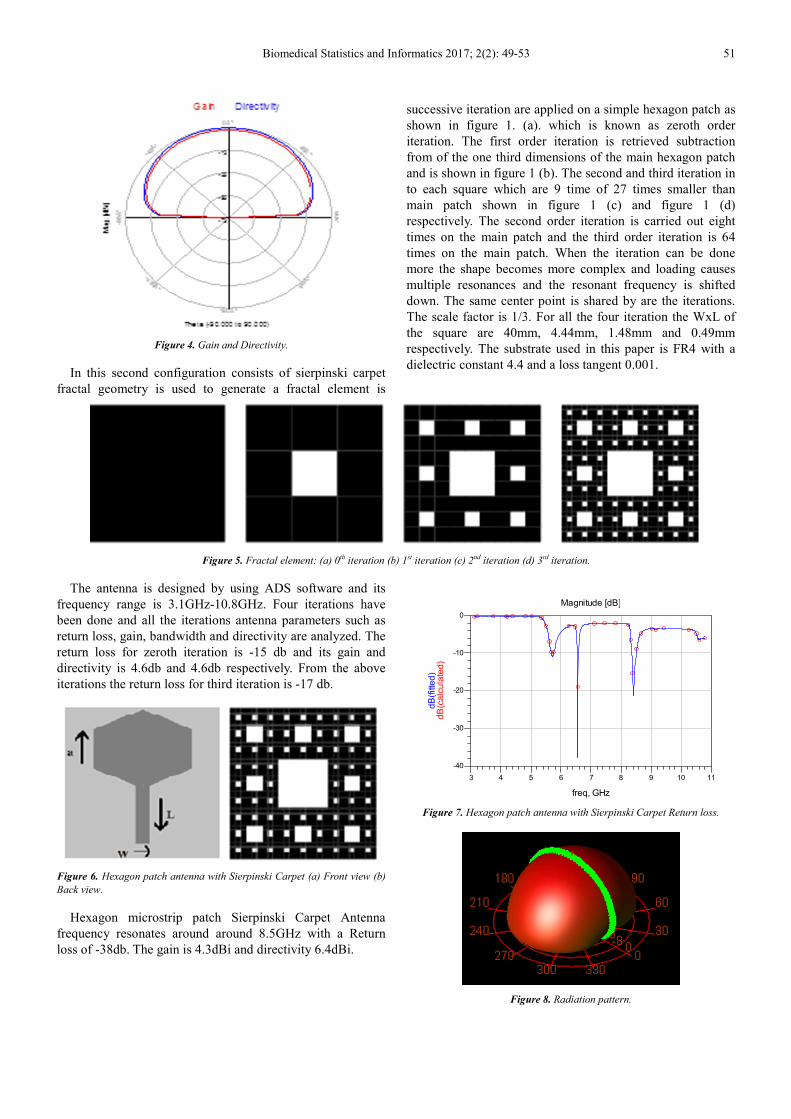
Hexagon patch Sierpinski carpets antenna using the FR-4
substrate with dielectric permittivity εr=4.4, thickness
h=1.6mm. The back side of the dielectric is entirely
recovered by a square ground plane with side length
WxL=40x40mm. The width and length of the microstrip feed
line are respectively W=3mm and L=13mm. This
configuration will be our reference antenna (antenna 1)
Figure 1. Geometry of the hexagon reference antenna.
The hexagon reference antenna frequency resonates
around 8.5GHz with a Return loss of -6db. The gain is 4.6dBi
and directivity 6.4dBi.
Figure 2. Return loss of the hexagon reference antenna.
Figure 3. Radiation pattern.
4 5 6 7 8 9 103 11
-8
-6
-4
-2
-10
0
freq, GHz
dB
(ca
lcu
late
d)
dB
(fitte
d)
Magnitude [dB]
Biomedical Statistics and Informatics 2017; 2(2): 49-53 51
Figure 4. Gain and Directivity.
In this second configuration consists of sierpinski carpet
fractal geometry is used to generate a fractal element is
successive iteration are applied on a simple hexagon patch as
shown in figure 1. (a). which is known as zeroth order
iteration. The first order iteration is retrieved subtraction
from of the one third dimensions of the main hexagon patch
and is shown in figure 1 (b). The second and third iteration in
to each square which are 9 time of 27 times smaller than
main patch shown in figure 1 (c) and figure 1 (d)
respectively. The second order iteration is carried out eight
times on the main patch and the third order iteration is 64
times on the main patch. When the iteration can be done
more the shape becomes more complex and loading causes
multiple resonances and the resonant frequency is shifted
down. The same center point is shared by are the iterations.
The scale factor is 1/3. For all the four iteration the WxL of
the square are 40mm, 4.44mm, 1.48mm and 0.49mm
respectively. The substrate used in this paper is FR4 with a
dielectric constant 4.4 and a loss tangent 0.001.
Figure 5. Fractal element: (a) 0th iteration (b) 1st iteration (c) 2nd iteration (d) 3rd iteration.
The antenna is designed by using ADS software and its
frequency range is 3.1GHz-10.8GHz. Four iterations have
been done and all the iterations antenna parameters such as
return loss, gain, bandwidth and directivity are analyzed. The
return loss for zeroth iteration is -15 db and its gain and
directivity is 4.6db and 4.6db respectively. From the above
iterations the return loss for third iteration is -17 db.
Figure 6. Hexagon patch antenna with Sierpinski Carpet (a) Front view (b)
Back view.
Hexagon microstrip patch Sierpinski Carpet Antenna
frequency resonates around around 8.5GHz with a Return
loss of -38db. The gain is 4.3dBi and directivity 6.4dBi.
Figure 7. Hexagon patch antenna with Sierpinski Carpet Return loss.
Figure 8. Radiation pattern.
4 5 6 7 8 9 103 11
-30
-20
-10
-40
0
freq, GHz
dB
(ca
lcu
late
d)
dB
(fitte
d)
Magnitude [dB]
52 T. Jayanthy and D. Rajeswari: Design and Analysis of Hexagon Microstrip Patch Sierpinski Carpet Antenna
Figure 9. Gain and Directivity.
The third configuration (antenna 3) consists of adding a
shorting pin situated on the straight line connecting the tip to
the bottom side of the hexagon. The final structure is
presented in figure 10.
Figure 10. Compact hexagon antenna with fractal and shorting pin.
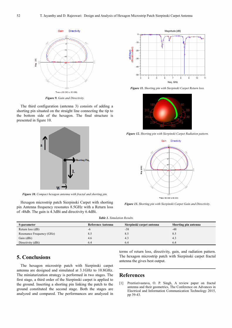
Hexagon microstrip patch Sierpinski Carpet with shorting
pin Antenna frequency resonates 8.5GHz with a Return loss
of -48db. The gain is 4.3dBi and directivity 6.4dBi.
Figure 11. Shorting pin with Sierpinski Carpet Return loss.
Figure 12. Shorting pin with Sierpinski Carpet Radiation pattern.
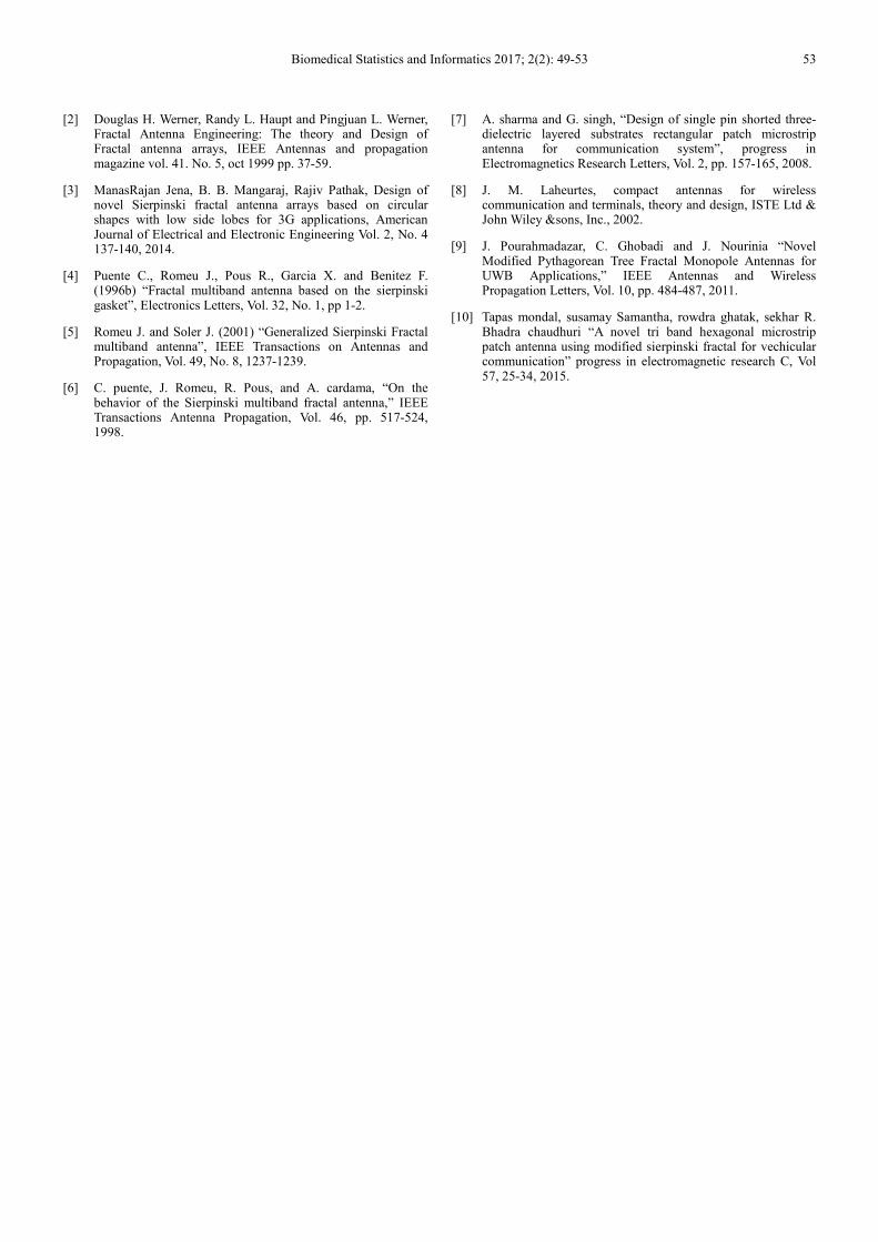
Figure 13. Shorting pin with Sierpinski Carpet Gain and Directivity.
Table 1. Simulation Results.
S-parameter Reference Antenna Sierpinski carpet antenna Shorting pin antenna
Return loss (dB) -6 -38 -48
Resonance Frequency (GHz) 8.5 8.5 8.5
Gain (dBi) 4.6 4.3 4.3
Directivity (dBi) 6.4 6.4 6.4
5. Conclusions
The hexagon microstrip patch with Sierpinski carpet
antenna are designed and simulated at 3.1GHz to 10.8GHz.
The miniaturization strategy is performed in two stages. The
first stage, a third order of the Sierpinski carpet is applied to
the ground. Inserting a shorting pin linking the patch to the
ground constituted the second stage. Both the stages are
analyzed and compared. The performances are analyzed in
terms of return loss, directivity, gain, and radiation pattern.
The hexagon microstrip patch with Sierpinski carpet fractal
antenna the gives best output.
References
[1] Preetisrivastava, O. P. Singh, A review paper on fractal antenna and their geometrics, The Conference on Advances in Electrical and Information Communication Technology 2015, pp 39-43.
4 5 6 7 8 9 103 11
-40
-30
-20
-10
-50
0
freq, GHz
dB
(calc
ula
ted)
dB
(fitte
d)
Magnitude [dB]
Biomedical Statistics and Informatics 2017; 2(2): 49-53 53
[2] Douglas H. Werner, Randy L. Haupt and Pingjuan L. Werner, Fractal Antenna Engineering: The theory and Design of Fractal antenna arrays, IEEE Antennas and propagation magazine vol. 41. No. 5, oct 1999 pp. 37-59.
[3] ManasRajan Jena, B. B. Mangaraj, Rajiv Pathak, Design of novel Sierpinski fractal antenna arrays based on circular shapes with low side lobes for 3G applications, American Journal of Electrical and Electronic Engineering Vol. 2, No. 4 137-140, 2014.
[4] Puente C., Romeu J., Pous R., Garcia X. and Benitez F. (1996b) “Fractal multiband antenna based on the sierpinski gasket”, Electronics Letters, Vol. 32, No. 1, pp 1-2.
[5] Romeu J. and Soler J. (2001) “Generalized Sierpinski Fractal multiband antenna”, IEEE Transactions on Antennas and Propagation, Vol. 49, No. 8, 1237-1239.
[6] C. puente, J. Romeu, R. Pous, and A. cardama, “On the behavior of the Sierpinski multiband fractal antenna,” IEEE Transactions Antenna Propagation, Vol. 46, pp. 517-524, 1998.
[7] A. sharma and G. singh, “Design of single pin shorted three-dielectric layered substrates rectangular patch microstrip antenna for communication system”, progress in Electromagnetics Research Letters, Vol. 2, pp. 157-165, 2008.
[8] J. M. Laheurtes, compact antennas for wireless communication and terminals, theory and design, ISTE Ltd & John Wiley &sons, Inc., 2002.
[9] J. Pourahmadazar, C. Ghobadi and J. Nourinia “Novel Modified Pythagorean Tree Fractal Monopole Antennas for UWB Applications,” IEEE Antennas and Wireless Propagation Letters, Vol. 10, pp. 484-487, 2011.
[10] Tapas mondal, susamay Samantha, rowdra ghatak, sekhar R. Bhadra chaudhuri “A novel tri band hexagonal microstrip patch antenna using modified sierpinski fractal for vechicular communication” progress in electromagnetic research C, Vol 57, 25-34, 2015.