Embed Size (px)
Citation preview
International Research Journal of Engineering and Technology (IRJET) e-ISSN: 2395 -0056
Volume: 03 Issue: 04 | Apr-2016 www.irjet.net p-ISSN: 2395-0072
© 2016, IRJET ISO 9001:2008 Certified Journal Page 2925
DESIGN AND ANALYSIS OF HIGH SPEED MOTORIZED SPINDLE
S.Vinoth 1, T.Azhagu Murugan 2
1S.Vinoth, Assistant Professor, Department of Mechanical Engineering, Mahendra College, Salem, TamilNadu, India 2 T.Azhagu Murugan, UG Scholar, Department of Mechanical Engineering, Mahendra College, Salem, TamilNadu,
India
---------------------------------------------------------------------***---------------------------------------------------------------------Abstract - Motorized spindle is one of the core parts of high-speed machine tool to a great extent, its thermal characteristics determine the thermal stress and thermal deformations and therefore the research on thermal characteristics is of great significance to increase the accuracy of high-speed machine tool. The motorized spindle is modeled, its thermal and dynamic characteristics analysis are carried out by finite element method using ANSYS software. It provides a powerful theoretical basis for reducing temperature–rise, calculating thermal deformations and improving working conditions of the high speed spindle. The results of temperature rise are used to determine the working speed of the spindle without bearing failure. The modal analysis was conducted for finding natural frequency, corresponding stress and displacement of the motorized spindle.
Key Words: FEA, ANSYS, Thermal Deformation, Failure.
1.INTRODUCTION ( Size 11 , cambria font) Manufacturers are constantly looking for various ways and means to improve the productivity of machine tools through improved power densities, higher speeds, greater flexibility, and more multitasking of operations. One important method to achieve this is by continual innovation and improvement of spindles. A spindle plays a vital role in the quality of the final product and enhances the overall productivity and efficiency of the machine tool itself. Today's spindle designs offer the manufacturers and machine builders much greater performance and reliability than ever before. Users can increase productivity in any industry by properly applying the advanced spindle technologies in specific applications. The powerful, flexible and faster machine tool spindles can reduce the number of cuts and making holes in manufacturing by half. High-speed spindles are more or less designed with the motor directly flanged to the spindle shaft High speed, precision, ultra-precise machining technology is an important trend of advanced manufacturing engineering, and high speed machining is a promising advanced manufacturing technology for increasing productivity and reducing production costs dramatically. High speed machine tool is the precondition for realizing
high speed machining. The high speed motorized spindle is the technical precondition and foundation, and the improvement of its speed and rigidity is very hot to research, thus high speed motorized spindle technology is of great significance to the research and development of high - speed machine tool. Compared with conventional spindle motorized spindle is equipped with a built-in motor, so that power transmission devices such as gears and belts are eliminated and "zero transmission" is realized.
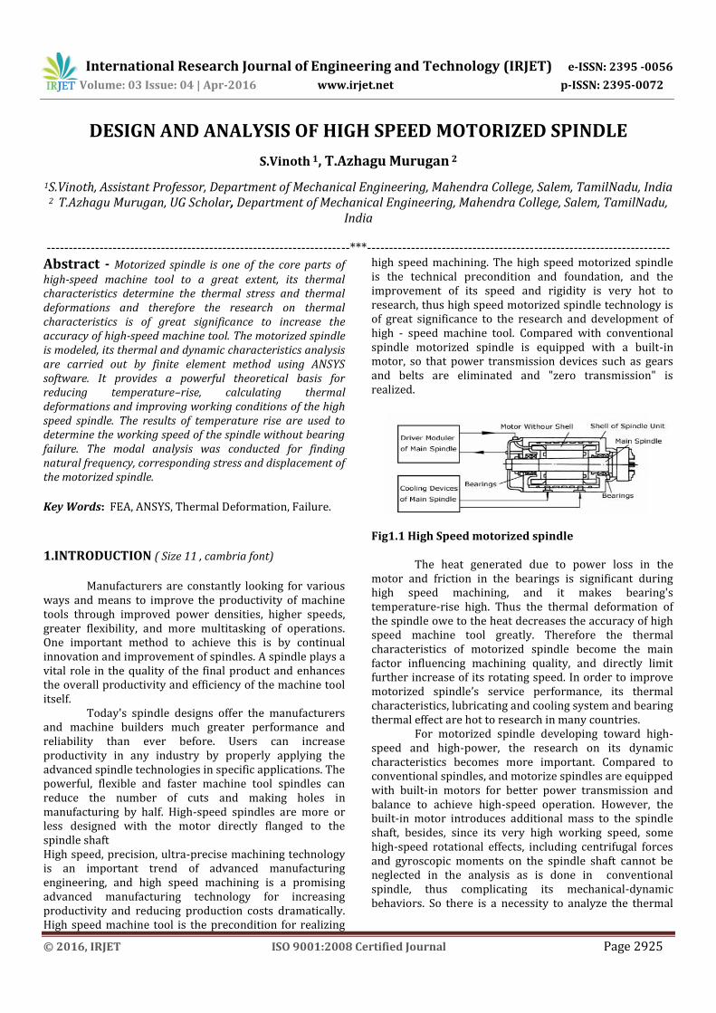
Fig1.1 High Speed motorized spindle The heat generated due to power loss in the motor and friction in the bearings is significant during high speed machining, and it makes bearing's temperature-rise high. Thus the thermal deformation of the spindle owe to the heat decreases the accuracy of high speed machine tool greatly. Therefore the thermal characteristics of motorized spindle become the main factor influencing machining quality, and directly limit further increase of its rotating speed. In order to improve motorized spindle’s service performance, its thermal characteristics, lubricating and cooling system and bearing thermal effect are hot to research in many countries. For motorized spindle developing toward high-speed and high-power, the research on its dynamic characteristics becomes more important. Compared to conventional spindles, and motorize spindles are equipped with built-in motors for better power transmission and balance to achieve high-speed operation. However, the built-in motor introduces additional mass to the spindle shaft, besides, since its very high working speed, some high-speed rotational effects, including centrifugal forces and gyroscopic moments on the spindle shaft cannot be neglected in the analysis as is done in conventional spindle, thus complicating its mechanical-dynamic behaviors. So there is a necessity to analyze the thermal
International Research Journal of Engineering and Technology (IRJET) e-ISSN: 2395 -0056
Volume: 03 Issue: 04 | Apr-2016 www.irjet.net p-ISSN: 2395-0072
© 2016, IRJET ISO 9001:2008 Certified Journal Page 2926
and dynamic characteristics of high speed Motorized spindle.
2. LITERATURE REVIEW Y. Lu Y.X. Yao and R.H. Hong et al (2008) has reviewed that thermal characteristics like the thermal stress and thermal deformations. Thermal characteristics are of great significance to increase the accuracy of high-speed machine tool. The heat generation developed in the built-in motor and the bearings is calculated. The motorized spindle is modeled and its thermal characteristics analysis by finite element method is done using ANSYS software, in the foundation of analyzing its configuration and heat transfer. The variation regularity of its temperature-rise and temperature field is also summarized. There by it provides a powerful theoretical basis for reducing temperature–rise, calculating thermal deformations and improving working conditions. The heat generated in motor mainly is the heat generated due to copper loss in stator winding and iron loss in rotor, and the heat generated due to copper loss in stator winding almost has 2/3 among total heating value. (1) Y. Lu Y.X. Yao and W.Z. Xie et al (2008) in this paper the FEM model of motorized spindle is set up to research on its dynamic characteristics in theory with an eye to high-speed rotational effects, including centrifugal forces and gyroscopic moments on the motorized spindle shaft. The motorized spindle’s natural frequencies and corresponding vibration shapes are got through the modal analysis, and the effect of the axial preload on the natural frequency is programmed. For the structure of spindle is symmetry and its shape is simple, some measures are done to simplify the calculation when modeling in FEM, including treating the spindle as the space spring beam, treating the angular contact ceramic ball bearing as a radial compression spring mass unit, treating the rotor, jacket and socket as the axial material with same density, equaling to node in relevant unit as the additional distributing mass in spindle.,(2) Jenq-Shyong Chen and Wei-Yao Hsu. et al [3] in this paper, the characterizing and modeling of the thermal growth of a motorized high speed spindle are reported. A motorized high speed spindle has more complicated dynamic, non-stationary and speed-dependent thermal characteristics than conventional spindles. The centrifugal force and thermal expansion occurring on the bearings and motor rotor change the thermal characteristics of the built-in motor, bearings and assembly joints. A new thermal model which correlates the spindle thermal growth to thermal displacements measured at some locations of the rotating spindle shaft has been proposed. It was found that the displacement-based thermal error model has much better accuracy and robustness than the temperature-based model Chi-Wei Lin a, Jay F. Tu a Joe Kamman et al (2003) in this paper the integrated model with experimental validation and sensitivity analysis for studying various thermo-mechanical-dynamic spindle behaviors at high
speeds.The integrated model to characterize mechanical and thermal influences on the dynamic behaviors of motorized spindles during very high-speed rotation. The thermal characterization of a complete motorized spindle was reported in. This thermal model predicts the temperature field of an entire motorized spindle and major heat sources, such as the built-in motor and the bearings. The temperature field of the entire spindle provides two important thermal influences on the dynamic model to be developed in this section. First, it provides the shaft geometry after thermal expansion. This influence is usually minor. The second influences on how the thermal expansions of the shaft, the bearing, and the housing are combined to affect bearing preload (thermally-induced preload) and subsequently bearing stiffness. (4) Bernd Bossmanns, Jay F. Tu et al (1999) was investigated Lack of a more complete understanding of the system characteristics, particularly thermal effects, severely limits the reliability of high speed spindles to support manufacturing. High speed spindles are notorious for their sudden catastrophic failures without alarming signs at high speeds due to thermal problems.The finite difference thermal model is developed to characterize the power distribution of a high speed motorized spindle, in particular the characterization of heat transfer and heat sinks. Without loss of generality, this model is built upon and verified by a custom-built high performance motorized milling spindle of 32 KW and maximum speed of 25 000 rpm (1.5 million DN). Deping Liu, Hang Zhang, Zheng Tao and Yufeng Su et al (2011) was investigated the characteristics of a high-speed motorized spindle system. The geometric quality of high-precision parts is highly dependent on the dynamic performance of the entire machining system, which is determined by the interrelated dynamics of machine tool mechanical structure and cutting process. The state-of-the-art in machine tool main spindle units is focus on motorized spindle units for high-speed and high performance cutting. Taking the high-speed milling motorized spindle of CX8075 produced by Anyang Xinsheng Machine Tool Co. Ltd. as an example, a finite element model of the high-speed motorized spindle is derived and presented. The model takes into account bearing support contact interface, which is established by spring-damper element COMBIN 14. Furthermore, the static analysis, modal analysis, harmonic response analysis and thermal analysis were done by means of ANSYS. NagarajArakereTony L. SchmitzChi et al was investigated in high-speed machining, the maximum stable depth of cut at any spindle rotating frequency depends on the spindle-holder-tool dynamic stiffness as reflected at the tool’s free end. Because this dynamic stiffness can vary with rotating frequency, we have modeled the spindle dynamic response using a finite element-based rotor dynamics approach.
International Research Journal of Engineering and Technology (IRJET) e-ISSN: 2395 -0056
Volume: 03 Issue: 04 | Apr-2016 www.irjet.net p-ISSN: 2395-0072
© 2016, IRJET ISO 9001:2008 Certified Journal Page 2927
3.MATERIAL SELECTION 3.1BEARINGS The angular contact ball bearing details used for finding radial stiffness, heat generation, and convection are given in the table 3.1 Table3 .1 Bearing details Bearing Front-I set Front-II set Rear Units
Contact angle 25 25 18 °
Inner diameter 90 80 70 mm Outer diameter 140 125 110 mm
Mean diameter 115 102.5 90 mm
Width 24 22 20 mm Mass 1.22
0.85 0.605 Kg
3.2 STRUCTURAL STEEL The properties of the structural steel which is used to construct the high speed motorized spindle, is given in the table 5.2 Table 3.2 properties of structural steel Density (p) 7870 Kg/m3
Modulus of elasticity( E) 200 GPa
Poisson’s ratio 0.296 - Shear Modulus (G) 80 GPa
Specific heat capacity (Cp) 486 J/Kgk
Thermal conductivity (K) 51.9 W/m-k
3.3 LUBRICANT The properties of grease and oil lubricants which are used in the angular contact ball bearing as lubricant and coolant, are given in the table 5.3 Table 3.3 Properties of grease and oil lubrication Properties Grease Oil Unit
Kinematic viscosity(µ) 22
60
m2/s
Absolute viscosity(Ƞ) 20.1
48.9
Ns/m2
Thermal conductivity(K) 0.144
0.113
W/m-k
Specific heat(Cp) 1700
960
J/Kgk
3.4 COOLANT The properties of the coolant which is used in the coolant jacket which is placed over the Stator of the motor to remove the heat generation, is given in the table 5.4 Table 3.4 Properties of coolant Properties Coolant unit Density 7800 Kg/m3
Flow rate 0.17x10⁻³ m3/s
Velocity 2.33 m/s Specific heat( Cp) 1870 J/kg k
THERMAL ANALYSIS 6.1 HEAT GENERATION The heat generations of motorized spindle are due to the power loss of motor, and bearing friction are calculated below. 6.1.1 Heat generation in the motor
Heat generation in the motor has been calculated from power loss. The 20000 rpm gives power losses of 334000 W. The heat generation in the stator is equal to the 2/3 of the power loss and heat generation in the rotor is equal to 1/3 of the power loss.
Heat generation in the stator=2226.65W Heat generation in the rotor=1113.35W
Table 6.1 Heat generation in spindle parts Spindle parts Total heat
generation(W)
Bearing –I 185.78
Bearing –II 193.24
Stator 2226
Rotor 1113
Table 6.2 Convection heat transfer in spindle parts Spindle parts convection(W/m2.K)
Bearing –I 178.54
Bearing –II 159.85
Rotor end’s surface 161.4
Ambient temperature °C
25
6.3 THERMAL ANALYSIS USING FEA The Limits of a spindle speed, reliability and performance are usually constrained by properties of its bearings, which are affected by the uneven thermal expansion of spindle Parts and degraded condition of lubricants due to high temperature. The most significant parameter affecting the spindle thermal displacement is the friction heat in the front and back bearings of the spindle. When the spindle rotates, heat occurs at the front and back bearings because of friction, and the heat is then transmitted to the spindle head and tool header etc. Thermal displacement consequently occurred at the spindle because of temperature increase. 6.4 The Finite Element Model of Thermal Analysis
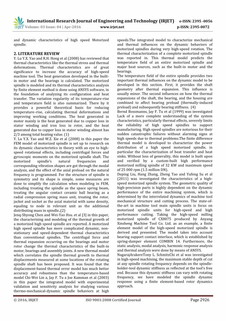
The spindle was modeled by using solid work 3D modeling software. Since the spindle and loading and boundary condition are axis symmetric its vertical axis.
International Research Journal of Engineering and Technology (IRJET) e-ISSN: 2395 -0056
Volume: 03 Issue: 04 | Apr-2016 www.irjet.net p-ISSN: 2395-0072
© 2016, IRJET ISO 9001:2008 Certified Journal Page 2928
Fig.6.2 Finite Element Model
Thermal structural analysis
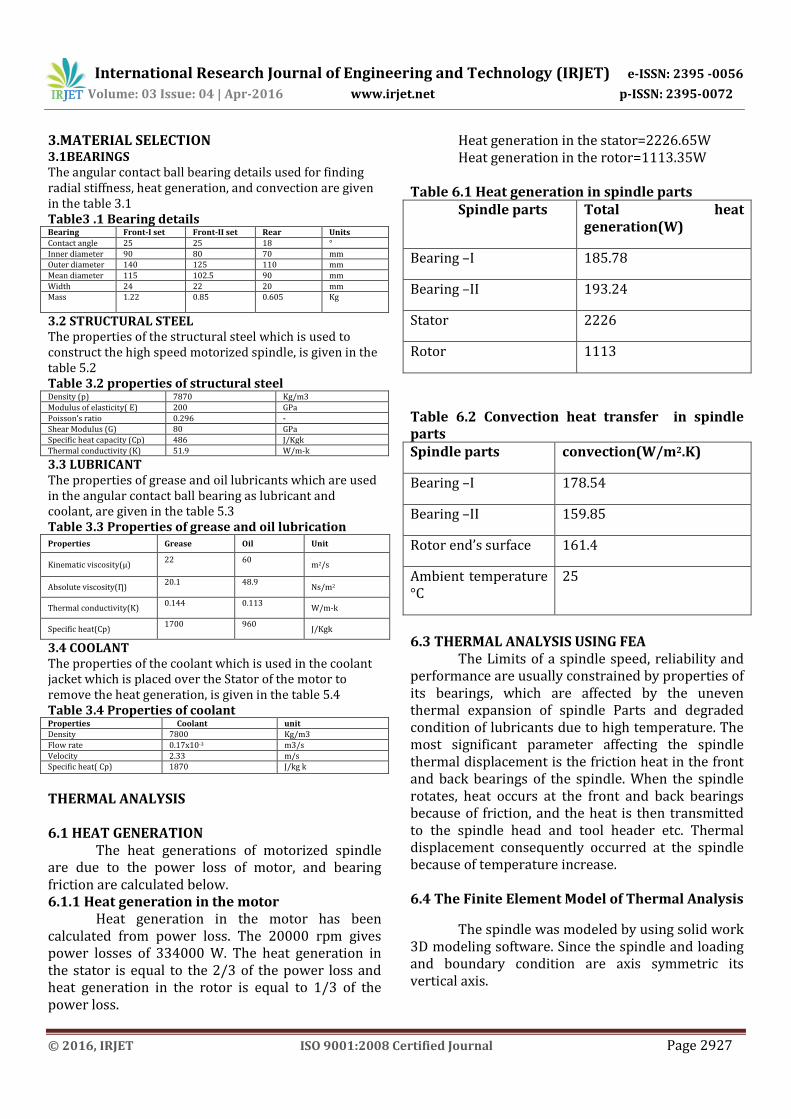
Fig.6.3 Radial thermal deflection Thermal structural analysis is done and radial and axial deflection are shown in fig. 6.3and 6.4 shows that the structural analysis spindle system the radial deflections are analyzed. If the boundary condition is to arrest the spindle two ends and give the machining time periods and spindle deflection value are tabulated . Table 6.3 The Radial deflection of spindle in various machining time
Machining Time (sec)
Radial deflection of spindle (µm)
Front End Rear End
2000 2 1
6000 7 4
10000 13 7
16000 21 16
20000 26 20
Fig 6.4Axial thermal deflection Table 6.4 The axial deflection of spindle in various machining time
Machining Time (sec)
Axial deflection of spindle (µm)
Front End Rear End
2000 8 10
6000 15 20
10000 34 40
16000 66 70
22000 95 100
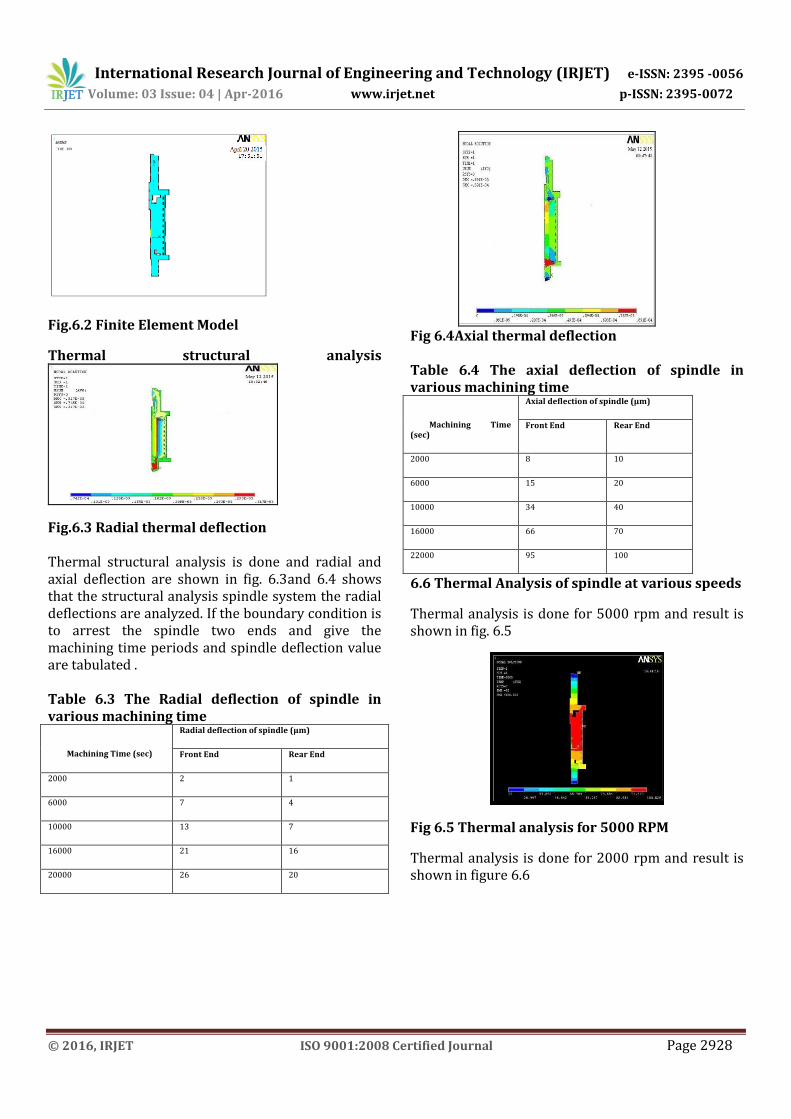
6.6 Thermal Analysis of spindle at various speeds
Thermal analysis is done for 5000 rpm and result is shown in fig. 6.5
Fig 6.5 Thermal analysis for 5000 RPM
Thermal analysis is done for 2000 rpm and result is shown in figure 6.6
International Research Journal of Engineering and Technology (IRJET) e-ISSN: 2395 -0056
Volume: 03 Issue: 04 | Apr-2016 www.irjet.net p-ISSN: 2395-0072
© 2016, IRJET ISO 9001:2008 Certified Journal Page 2929
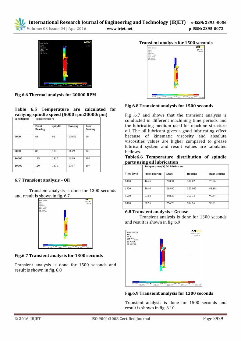
Fig 6.6 Thermal analysis for 20000 RPM
Table 6.5 Temperature are calculated for variying spindle speed (5000 rpm20000rpm) Speed(rpm) Temperature oc
Front Bearing
spindle Housing Rear Bearing
5000
64 92 100.52 60
8000 83 104 114.9 72
16000 115 141.7 163.9 100
20000 120 147.1 176.7 107
6.7 Transient analysis – Oil Transient analysis is done for 1300 seconds and result is shown in fig. 6.7
Fig.6.7 Transient analysis for 1300 seconds
Transient analysis is done for 1500 seconds and result is shown in fig. 6.8
Transient analysis for 1500 seconds
Fig.6.8 Transient analysis for 1500 seconds
Fig .6.7 and shows that the transient analysis is conducted in different machining time periods and the lubricating medium used for machine structure oil. The oil lubricant gives a good lubricating effect because of kinematic viscosity and absolute viscosities values are higher compared to grease lubricant system and result values are tabulated bellows. Table6.6 Temperature distribution of spindle parts using oil lubrication
Time (sec)
Temperature (K) Oil lubrication
Front Bearing Shaft Housing Rear Bearing
1000 46.45 200.34 300.02 78.56
1300 50.40 218.90 320.002 84.10
1500 57.02 248.29 362.34 95.34
2000 62.56 256.73 384.16 98.31
6.8 Transient analysis – Grease Transient analysis is done for 1300 seconds and result is shown in fig. 6.9
Fig.6.9 Transient analysis for 1300 seconds
Transient analysis is done for 1500 seconds and result is shown in fig. 6.10
International Research Journal of Engineering and Technology (IRJET) e-ISSN: 2395 -0056
Volume: 03 Issue: 04 | Apr-2016 www.irjet.net p-ISSN: 2395-0072
© 2016, IRJET ISO 9001:2008 Certified Journal Page 2930
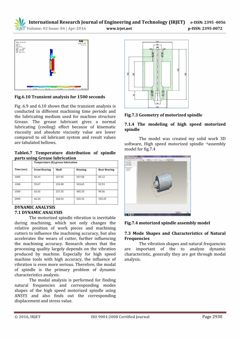
Fig.6.10 Transient analysis for 1500 seconds
Fig .6.9 and 6.10 shows that the transient analysis is conducted in different machining time periods and the lubricating medium used for machine structure Grease. The grease lubricant gives a normal lubricating (cooling) effect because of kinematic viscosity and absolute viscosity value are lower compared to oil lubricant system and result values are tabulated bellows. Table6.7 Temperature distribution of spindle parts using Grease lubrication
Time (sec)
Temperature (K) grease lubrication
Front Bearing Shaft Housing Rear Bearing
1000 50.34 227.45 337.58 83.12
1300 55.67 234.98 343.65 92.53
1500 63.65 257.35 405.33 98.56
2000 66.34 268.34 420.34 105.45
DYNAMIC ANALYSIS 7.1 DYNAMIC ANALYSIS The motorized spindle vibration is inevitable during machining, which not only changes the relative position of work pieces and machining cutters to influence the machining accuracy, but also accelerates the wears of cutter, further influencing the machining accuracy. Research shows that the processing quality largely depends on the vibration produced by machine. Especially for high speed machine tools with high accuracy, the influence of vibration is even more serious. Therefore, the modal of spindle is the primary problem of dynamic characteristics analysis. The modal analysis is performed for finding natural frequencies and corresponding modes shapes of the high speed motorized spindle using ANSYS and also finds out the corresponding displacement and stress value.
Fig.7.3 Geometry of motorized spindle
7.1.4 The modeling of high speed motorized spindle
The model was created my solid work 3D software, High speed motorized spindle -4assembly model for fig.7.4
Fig.7.4 motorized spindle assembly model 7.3 Mode Shapes and Characteristics of Natural Frequencies The vibration shapes and natural frequencies are important of the to analyze dynamic characteristic, generally they are got through modal analysis.
International Research Journal of Engineering and Technology (IRJET) e-ISSN: 2395 -0056
Volume: 03 Issue: 04 | Apr-2016 www.irjet.net p-ISSN: 2395-0072
© 2016, IRJET ISO 9001:2008 Certified Journal Page 2931
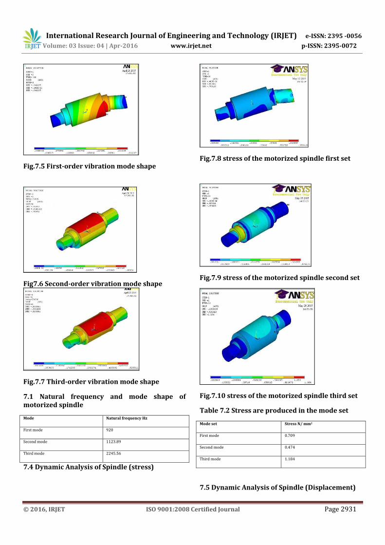
Fig.7.5 First-order vibration mode shape
Fig7.6 Second-order vibration mode shape
Fig.7.7 Third-order vibration mode shape
7.1 Natural frequency and mode shape of motorized spindle
Mode Natural frequency Hz
First mode 920
Second mode 1123.89
Third mode 2245.56
7.4 Dynamic Analysis of Spindle (stress)
Fig.7.8 stress of the motorized spindle first set
Fig.7.9 stress of the motorized spindle second set
Fig.7.10 stress of the motorized spindle third set
Table 7.2 Stress are produced in the mode set
Mode set Stress N/ mm2
First mode 0.709
Second mode 0.474
Third mode 1.184
7.5 Dynamic Analysis of Spindle (Displacement)
International Research Journal of Engineering and Technology (IRJET) e-ISSN: 2395 -0056
Volume: 03 Issue: 04 | Apr-2016 www.irjet.net p-ISSN: 2395-0072
© 2016, IRJET ISO 9001:2008 Certified Journal Page 2932
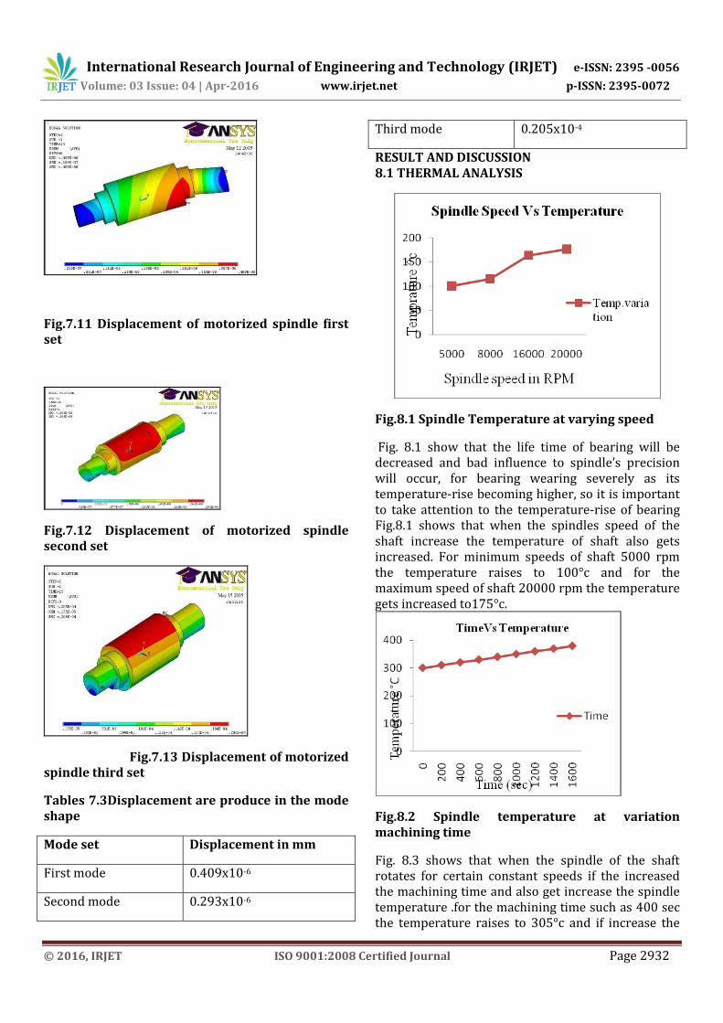
Fig.7.11 Displacement of motorized spindle first set
Fig.7.12 Displacement of motorized spindle second set
Fig.7.13 Displacement of motorized spindle third set
Tables 7.3Displacement are produce in the mode shape
Mode set Displacement in mm
First mode 0.409x10⁻⁶
Second mode 0.293x10⁻⁶
Third mode 0.205x10⁻⁴
RESULT AND DISCUSSION 8.1 THERMAL ANALYSIS
Fig.8.1 Spindle Temperature at varying speed
Fig. 8.1 show that the life time of bearing will be decreased and bad influence to spindle’s precision will occur, for bearing wearing severely as its temperature-rise becoming higher, so it is important to take attention to the temperature-rise of bearing Fig.8.1 shows that when the spindles speed of the shaft increase the temperature of shaft also gets increased. For minimum speeds of shaft 5000 rpm the temperature raises to 100°c and for the maximum speed of shaft 20000 rpm the temperature gets increased to175°c.
Fig.8.2 Spindle temperature at variation machining time
Fig. 8.3 shows that when the spindle of the shaft rotates for certain constant speeds if the increased the machining time and also get increase the spindle temperature .for the machining time such as 400 sec the temperature raises to 305°c and if increase the
International Research Journal of Engineering and Technology (IRJET) e-ISSN: 2395 -0056
Volume: 03 Issue: 04 | Apr-2016 www.irjet.net p-ISSN: 2395-0072
© 2016, IRJET ISO 9001:2008 Certified Journal Page 2933
machining time such as 1600 sec the temperature raises 370°c.
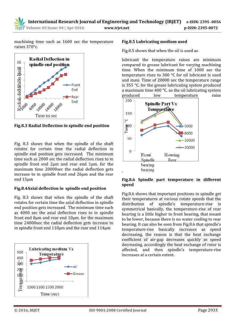
Fig.8.3 Radial Deflection in spindle end position
Fig. 8.3 shows that when the spindle of the shaft rotates for certain time the radial deflection in spindle end position gets increased. The minimum time such as 2000 sec the radial deflection rises to in spindle front end 2µm and rear end 1µm. for the maximum time 20000sec the radial deflection gets increase to in spindle front end 26µm and the rear end 15µm
Fig.8.4Axial deflection in spindle end position
Fig. 8.3 shows that when the spindle of the shaft rotates for certain time the axial deflection in spindle end position gets increased. The minimum time such as 4000 sec the axial deflection rises to in spindle front end 8µm and rear end 10µm. for the maximum time 24000sec the radial deflection gets increase to in spindle front end 110µm and the rear end 114µm
Fig.8.5 Lubricating medium used
Fig.8.5 shows that when the oil is used as
lubricant the temperature raises are minimum compared to grease lubricant for varying machining time. When the minimum time of 1000 sec the temperature rises to 300 °C for oil lubricant is used and maxi. Time of 20000 sec the temperature range is 355 °C. for the grease lubricating system produced a maximum time 400 °C. so the oil lubricating system produced low temperature raise
.
Fig.8.6 Spindle part temperature in different speed
Fig.8.6 shows that important positions in spindle get their temperatures at various rotate speeds that the distribution of spindle’s temperature-rise is symmetrical basically, the temperature-rise of rear bearing is a little higher to front bearing, that meant to be lower, because there is no water cooling to rear bearing. It can also be seen from Fig.8.6 that spindle’s temperature-rise basically increases as speed decreasing, the reason is that the heat exchange coefficient of air-gap decreases quickly as speed decreasing, accordingly the heat exchange of rotor is affected, and then spindle’s temperature-rise increases at a certain extent.
International Research Journal of Engineering and Technology (IRJET) e-ISSN: 2395 -0056
Volume: 03 Issue: 04 | Apr-2016 www.irjet.net p-ISSN: 2395-0072
© 2016, IRJET ISO 9001:2008 Certified Journal Page 2934
8.2 DYNAMIC MODAL ANALYSIS
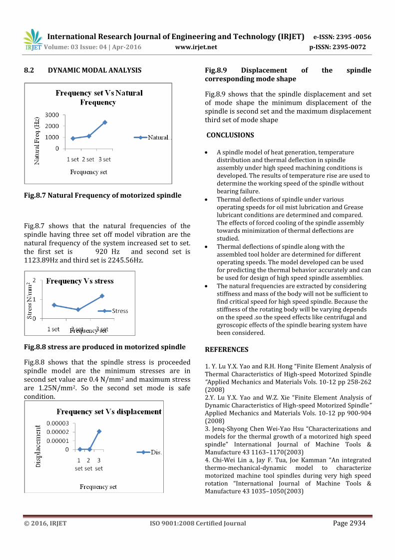
Fig.8.7 Natural Frequency of motorized spindle
Fig.8.7 shows that the natural frequencies of the spindle having three set off model vibration are the natural frequency of the system increased set to set. the first set is 920 Hz and second set is 1123.89Hz and third set is 2245.56Hz.
Fig.8.8 stress are produced in motorized spindle
Fig.8.8 shows that the spindle stress is proceeded spindle model are the minimum stresses are in second set value are 0.4 N/mm2 and maximum stress are 1.25N/mm2. So the second set mode is safe condition.
Fig.8.9 Displacement of the spindle corresponding mode shape
Fig.8.9 shows that the spindle displacement and set of mode shape the minimum displacement of the spindle is second set and the maximum displacement third set of mode shape
CONCLUSIONS A spindle model of heat generation, temperature
distribution and thermal deflection in spindle assembly under high speed machining conditions is developed. The results of temperature rise are used to determine the working speed of the spindle without bearing failure.
Thermal deflections of spindle under various operating speeds for oil mist lubrication and Grease lubricant conditions are determined and compared. The effects of forced cooling of the spindle assembly towards minimization of thermal deflections are studied.
Thermal deflections of spindle along with the assembled tool holder are determined for different operating speeds. The model developed can be used for predicting the thermal behavior accurately and can be used for design of high speed spindle assemblies.
The natural frequencies are extracted by considering stiffness and mass of the body will not be sufficient to find critical speed for high speed spindle. Because the stiffness of the rotating body will be varying depends on the speed .so the speed effects like centrifugal and gyroscopic effects of the spindle bearing system have been considered.
REFERENCES 1. Y. Lu Y.X. Yao and R.H. Hong “Finite Element Analysis of Thermal Characteristics of High-speed Motorized Spindle “Applied Mechanics and Materials Vols. 10-12 pp 258-262 (2008) 2.Y. Lu Y.X. Yao and W.Z. Xie “Finite Element Analysis of Dynamic Characteristics of High-speed Motorized Spindle” Applied Mechanics and Materials Vols. 10-12 pp 900-904 (2008) 3. Jenq-Shyong Chen Wei-Yao Hsu “Characterizations and models for the thermal growth of a motorized high speed spindle” International Journal of Machine Tools & Manufacture 43 1163–1170(2003) 4. Chi-Wei Lin a, Jay F. Tua, Joe Kamman “An integrated thermo-mechanical-dynamic model to characterize motorized machine tool spindles during very high speed rotation “International Journal of Machine Tools & Manufacture 43 1035–1050(2003)
International Research Journal of Engineering and Technology (IRJET) e-ISSN: 2395 -0056
Volume: 03 Issue: 04 | Apr-2016 www.irjet.net p-ISSN: 2395-0072
© 2016, IRJET ISO 9001:2008 Certified Journal Page 2935
5. Bernd Bossmanns, Jay F. Tu “A thermal model for high speed motorized spindles” International Journal of Machine Tools & Manufacture 39 1345–1366(1999) 6. Deping Liu*, Hang Zhang, Zheng Tao and YufengSu “Finite Element Analysis of High-Speed Motorized Spindle Based on ANSYS” School of Mechanical Engineering, Zhengzhou University, Zhengzhou 450001, China (2011) 7.Nagaraj Arakere, Assoc. Prof., Tony L. Schmitz, Asst. Prof., Chi-Hung Cheng“Rotor Dynamic Response of a High-Speed Machine Tool Spindle “University of Florida, Department of Mechanical and Aerospace Engineering 237 MAE-B, Gainesville, FL 32611 8.Jin Kyung Choi, Dai Gil Lee “Thermal characteristics of the spindle bearing system with a gear located on the bearing span ‘Department of Mechanical Engineering, Korea Advanced Institute of Science and Technology, ME3221, Gusongdong,Yusong-gu, Taejon-shi, South Korea 305-70 9.Jenq-Shyong Chen*, Kwan-Wen Chen “Bearing load analysis and control of a motorized high speed spindle “International Journal of Machine Tools & Manufacture 45 1487–1493(2005) 10.Mohammed A. Alfares*, Abdallah A. Elsharkawy “Effects of axial preloading of angular contact ball bearings on the dynamics of a grinding machine spindle system “Journal of Materials Processing Technology 136 48–59(2003)