Embed Size (px)
Citation preview
I J I T E • ISSN: 2229-73673(1-2), 2012, pp. 353-358
DESIGN AND ANALYSIS OF MICROSTRIP FEDSLOT ANTENNA FOR SMALL SATELLITE APPLICATIONS
ELAMARAN P.1 & ARUN V.2
1M.E-Communication systems, Anna University of Technology Madurai (E-mail: [email protected])2Assistant Professor, Dept of ECE, Anna University of technology Madurai.
Abstract: In this proposed work, a cavity backed microstrip fed slot antenna is designed for satellite applications.Two rectangular narrow slot antennas are placed in series. The slot is backed by cavity to improve the antennaperformance. When two serial slot antennas were placed close to each other, we found that one can achieve tworesonances, and this suggests a dual band antenna design. The spacing between the two antennas can be adjusted toachieve an effective secondary resonance. The new resonance is found to be due to the mutual coupling between thetwo slot antennas. This simulated antenna operates at 5.2GHz and 10.7GHz which are frequencies of C band and Xband respectively and these frequencies are used in small satellite communications. The proposed antenna can beintegrated with solar panels to save surface real estate of small satellites, and to replace traditional deployed dipoleantennas. Measured results show good return loss and radiation pattern at both frequencies.
Index Terms: Microstrip, mutual coupling, slot antennas.
1. INTRODUCTIONSlot antennas have appealing features such as lowprofile, low cost, and ease of integration on planaror non-planar surfaces. An example applicationis integrating slot antennas with solar panels ofsmall satellites to save surface real estate [4]. Whileslot antennas are valuable for space applicationsand self-powered ground sensors [5], mostdesigns are limited to single frequency operation.This communication presents a very simpledesign where one can achieve a dual bandantenna by utilizing coupling between twoadjacent slots.
A slot antenna, when not backed by a cavity,radiates to both sides of the ground plane and canbe a good substitute for a dipole antenna. Inapplications such as solar panel integration, it isimportant to limit the radiation to only the frontside of the slot by utilizing a cavity backing. Thecavity can be loaded with dielectrics to improveantenna performance, such as enhancing theimpedance bandwidth. Due to the conformalnature and versatility in choosing the cavitygeometry and material, cavity backed antennashave found popularity in both single elementimplementations and array configurations.
When there is more than one slot element, itis necessary to study the coupling betweenelements. It has been found that cavity backed slotantennas have small mutual coupling. Furtherstudies have been reported to compute thecoupling using numerical techniques andanalytical methods.
Although there is abundant literature oncavity backed slot antennas and their coupling,most studies have focused on studying the slotelements in parallel alignments. When the slotsare placed in series, the spacing between theelements is usually large enough (e.g., at least ahalf wavelength) for one to ignore the resonancedue to coupling. But when two series slot antennasare placed close to each other, we found that onecan achieve two resonances. This suggests a dualband antenna design. This communicationpresents the design method, analysis using anequivalent circuit modal, and a simulated dualband antenna. The antenna is studied usingAnsoft’s HFSS, and measured results agree wellwith the simulations, validating the dual bandantenna design that can be potentiallyimplemented on solar panels as communicationlinks or sensor nodes.
354 Elamarab P. & Arun V.
2. DUAL BAND ANTENNA ANALYSIS
The configuration of the proposed dual bandcavity backed slot antenna is shown in Figure 1.The antenna and the feed lines are composed oftwo circuit board substrates. Two radiating slotsare etched on the top layer, which is a copperlayer, of the first substrate. The feed lines areprinted on the top layer of the second substrate.The bottom layer of the second substrate is theground plane. The two substrates are thenassembled together with antennas on the topmostlayer and the feed lines sandwiched between thetwo substrates. Also, the antenna elements aredesigned and assembled to be orthogonal to thefeed lines (Figure 1). It should be noted that onedoes not have to choose the same substrates toetch antennas and to print feed lines. Dependingon applications and practical demands, theexcitation method can be simple probe feed [1],coplanar waveguide (CPW) feed [2], or microstripline feed [5]. This communication demonstrates
the microstrip line feed due to its simplicity andease in matching the lines to the slot antenna byadjusting the position and length of the feed lines.After assembling the two substrates, the fourside-walls of the substrates and the top plane (i.e.,slot antenna and the metal plane) are shorted tothe ground plane with either conductive pastesor conductive tapes.
Table 1Calculated Parameters of Slot Antenna
Name of the Parameters Values
Substrate 1 (Silicon, � r = 11.9) 3.38 mmthickness
Substrate 2 (Roger 4003C, � r = 3.55) .831 mmthickness
Substrate 1 and Substrate 2 Size 100 mmx 100 mm
Ground Size 200 mmx 200 mm
Slot Size 25.5 mmx 0.9 mm
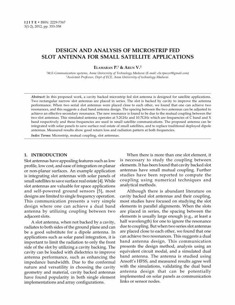
The feed design is a 50 �� microstrip linedivided into two 100 �� lines to excite the two slotelements that resonate at the same frequency(Figure 2). We found that when the two elementsare placed close, a new resonance appears due tothe strong coupling between the two slots. Theexplanation for the second resonance is that thecoupling between the two slots acts as if therewere an equivalent slot antenna that is longer thanthe individual slot but shorter than the total lengthof the two slot elements. In Table 1, the value ofthe all parameters is given.
Figure 1: Illustration of the Dual Band Antenna
Figure 2: Final HFSS Model of the Dual Band Slot Antenna
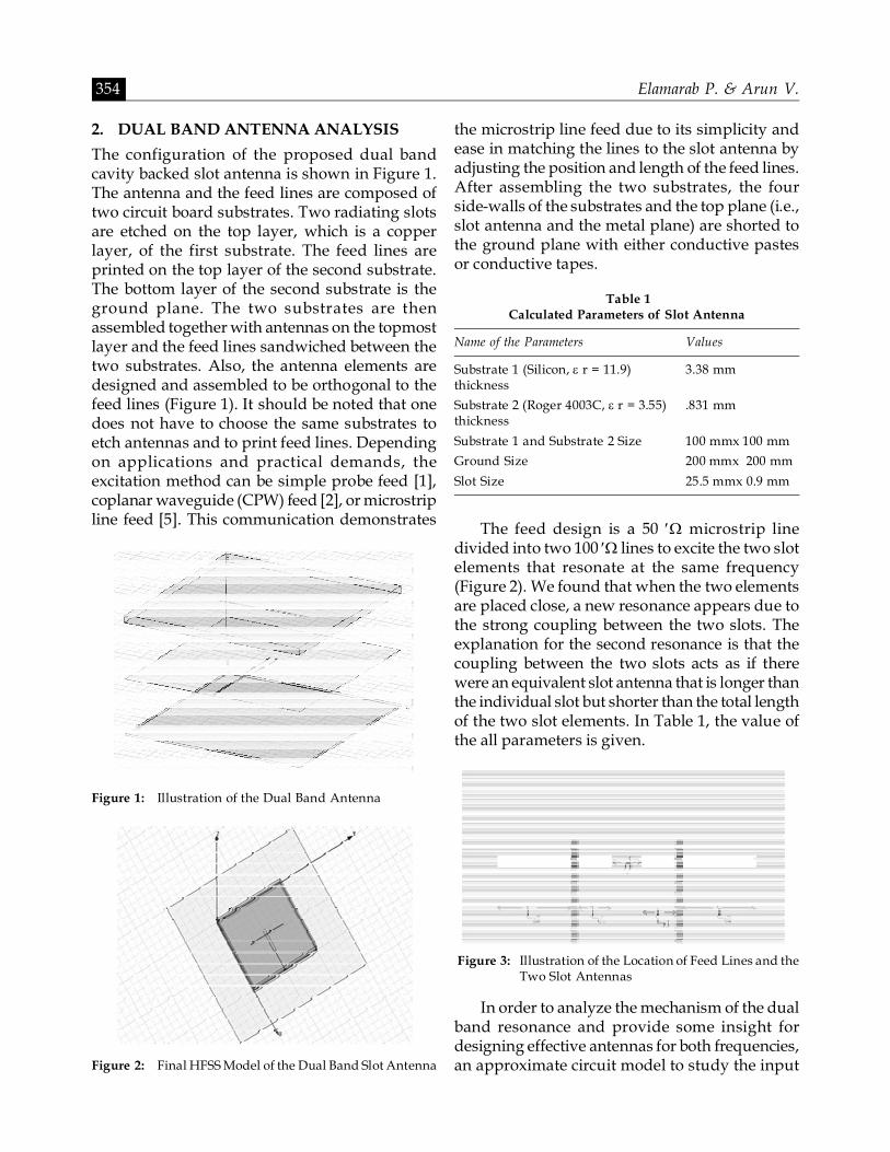
Figure 3: Illustration of the Location of Feed Lines and theTwo Slot Antennas
In order to analyze the mechanism of the dualband resonance and provide some insight fordesigning effective antennas for both frequencies,an approximate circuit model to study the input
Design and Analysis of Microstrip Fed Slot Antenna for Small Satellite… 355
impedance of the slot antenna is established. Theimportant parameters of the slot geometry aremarked in Figure 3, where Le1 and Le2 are criticalfor matching the impedance of the two slots, andthe spacing between the two slots (d in Figure 3)has been seen to affect the impedance of theequivalent slot.
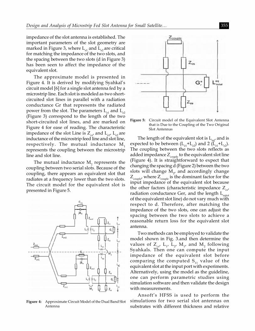
The approximate model is presented inFigure 4. It is derived by modifying Syahkal’scircuit model [6] for a single slot antenna fed by amicrostrip line. Each slot is modeled as two short-circuited slot lines in parallel with a radiationconductance Gr that represents the radiatedpower from the slot. The parameters Le1 and Le2
(Figure 3) correspond to the length of the twoshort-circuited slot lines, and are marked onFigure 4 for ease of reading. The characteristicimpedance of the slot Line is Zcs, and Le1, Le2 areinductance of the microstrip feed line and slot line,respectively. The mutual inductance M1
represents the coupling between the microstripline and slot line.
The mutual inductance M2 represents thecoupling between two serial slots. Because of thecoupling, there appears an equivalent slot thatradiates at a frequency lower than the two slots.The circuit model for the equivalent slot ispresented in Figure 5.
The length of the equivalent slot is Leq, and isexpected to be between (Le1+Le2) and 2 (Le1+Le2).The coupling between the two slots reflects asadded impedance Zcouple to the equivalent slot line(Figure 4). It is straightforward to expect thatchanging the spacing d (Figure 2) between the twoslots will change M2, and accordingly changeZcouple, where Zcouple is the dominant factor for theinput impedance of the equivalent slot becausethe other factors (characteristic impedance Zcs,radiation conductance Ger, and the length Leqtotof the equivalent slot line) do not vary much withrespect to d. Therefore, after matching theimpedance of the two slots, one can adjust thespacing between the two slots to achieve areasonable return loss for the equivalent slotantenna.
Two methods can be employed to validate themodel shown in Fig. 3.and then determine thevalues of Zcs, L1, L2, M1, and M2 followingSyahkals. Then one can compute the inputimpedance of the equivalent slot beforecomparing the computed S11 value of theequivalent slot at the input port with experiments.Alternatively, using the model as the guideline,one can perform parametric studies usingsimulation software and then validate the designwith measurements.
Ansoft’s HFSS is used to perform thesimulations for two serial slot antennas onsubstrates with different thickness and relative
Figure 4: Approximate Circuit Model of the Dual Band SlotAntenna
Figure 5: Circuit model of the Equivalent Slot Antennathat is Due to the Coupling of the Two OriginalSlot Antennas
356 Elamarab P. & Arun V.
permittivity, and different ground plane size. Itis found that after matching two identical serialslots to a resonant frequency f1, a secondaryresonance f2 appears when the spacing betweenthe two slots is less than 0.19 wavelengths. Whenthe dimension of the slots is fixed, the inputimpedance of the equivalent slot is mainlydetermined by Zcouple which is affected by themutual inductance M2 (Figure 4). It is alsoseen from Figure 4 that M2 affects the input impedances of two serial slots, and thereforethe spacing between them will affect S11 valueat f1.
3. MEASUREMENT RESULTS
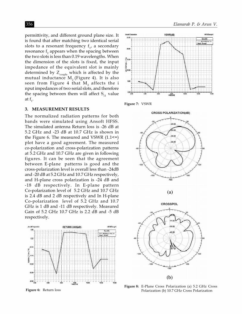
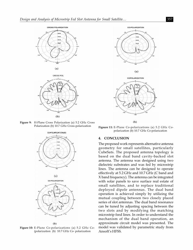
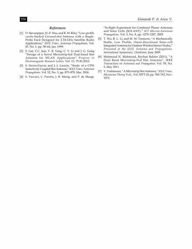
The normalized radiation patterns for bothbands were simulated using Ansoft HFSS.The simulated antenna Return loss is -26 dB at5.2 GHz and -23 dB at 10.7 GHz is shown inthe Figure 6. The measured and VSWR (1.1<=)plot have a good agreement. The measuredco-polarization and cross-polarization patternsat 5.2 GHz and 10.7 GHz are given in followingfigures. It can be seen that the agreementbetween E-plane patterns is good and thecross-polarization level is overall less than -24dBand -20 dB at 5.2 GHz and 10.7 GHz respectively,and H-plane cross polarization is -24 dB and-18 dB respectively. In E-plane patternCo-polarization level of 5.2 GHz and 10.7 GHzis 2.4 dB and 2 dB respectively and In H-planeCo-polarization level of 5.2 GHz and 10.7GHz is 1 dB and -11 dB respectively. MeasuredGain of 5.2 GHz 10.7 GHz is 2.2 dB and -5 dBrespectively.
Figure 6: Return loss
Figure 7: VSWR
Figure 8: E-Plane Cross Polarization (a) 5.2 GHz CrossPolarization (b) 10.7 GHz Cross Polarization
Design and Analysis of Microstrip Fed Slot Antenna for Small Satellite… 357
4. CONCLUSION
The proposed work represents alternative antennageometry for small satellites, particularlyCubeSats. The proposed antenna topology isbased on the dual band cavity-backed slotantenna. The antenna was designed using twodielectric substrates and was fed by microstriplines. The antenna can be designed to operateeffectively at 5.2 GHz and 10.7 GHz (C band andX band frequency). The antenna can be integratedwith solar panels to save surface real estate ofsmall satellites, and to replace traditionaldeployed dipole antennas. The dual bandoperation is achieved simply by utilizing themutual coupling between two closely placedseries of slot antennas. The dual band resonancecan be tuned by adjusting spacing between thetwo slots and by modifying the matchingmicrostrip feed lines. In order to understand themechanism of the dual band operation, anapproximate circuit model was presented. Themodel was validated by parametric study fromAnsoft’s HFSS.
Figure 9: H-Plane Cross Polarization (a) 5.2 GHz CrossPolarization (b) 10.7 GHz Cross-polarization
Figure 10: E-Plane Co-polarizations (a) 5.2 GHz Co-(polarization (b) 10.7 GHz Co- polarization
Figsure 11: E-Plane Co-polarizations (a) 5 .2 GHz Co-polarization (b) 10.7 GHz Co-polarization
358 Elamarab P. & Arun V.
References[1] D. Sievenpiper, H.-P. Hsu, and R. M. Riley “Low-profile
cavity-backed Crossed-slot Antenna with a Single-Probe Feed Designed for 2.34-GHz Satellite RadioApplications,” IEEE Trans. Antennas Propagations, Vol.47, No. 1, pp. 58–64, Jan. 1999.
[2] S. Gai, Y.C. Jiao, Y. B. Yang, C. Y. Li and J. G. Gong“Design of a Novel Microstrip-fed Dual-band SlotAntenna for WLAN Applications” Progress inElectromagnetic Research Letters, Vol. 13, 75-81,2010.
[3] S. Sierra-Garcia and J.-J. Laurin, “Study of a CPWInductively Coupled Slot Antenna,” IEEE Trans. AntennasPropagations. Vol. 52, No. 3, pp. 873–879, Mar. 2004.
[4] S. Vaccaro, C. Pereira, J. R. Mosig, and P. de Maagt,
“In-flight Experiment for Combined Planar Antennasand Solar Cells (SOLANT),” IET Microw.AntennasPropagations, Vol. 3, No. 8, pp. 1279–1287, 2009.
[5] T. Wu, R. L. Li, and M. M. Tentzeris, “A MechanicallyStable, Low Profile, Omni-directional Solar-cellIntegrated Antenna for Outdoor Wireless Sensor Nodes,”Presented at the IEEE Antenna and Propagations.International Symposium, Charleston, June 2009.
[6] Mahmoud N. Mahmoud, Reyhan Baktur (2011), “ADual Band Microstrip-Fed Slot Antenna”, IEEETransactions on Antennas and Propagation, Vol. 59, No.5, May 2011.
[7] Y. Yoshimura, “A Microstrip Slot Antenna,” IEEE Trans.Microwave.Theory Tech., Vol. MTT-20, pp. 760–762, Nov.1972.


![Printed Egg Curved Slot Antennas for Wideband Applications · wide-slot antenna fed by a microstrip line with a rotated slot for bandwidth enhancement is proposed in [1] with operating](https://img.pdfslide.net/doc/110x75/5fd1ea513ac4222b78003805/printed-egg-curved-slot-antennas-for-wideband-wide-slot-antenna-fed-by-a-microstrip.jpg)


![Compact and Broadband Microstrip-Line-Fed Modified …tie slot antenna with a rectangular tuning stub [14] or a coplanar waveguide (CPW)-fed rhombus slot antenna with a rhombic ring](https://img.pdfslide.net/doc/110x75/5e350409078c6c664e67ae66/compact-and-broadband-microstrip-line-fed-modified-tie-slot-antenna-with-a-rectangular.jpg)