Embed Size (px)
Citation preview
International Research Journal of Engineering and Technology (IRJET) e-ISSN: 2395 -0056
Volume: 03 Issue: 04 | Apr-2016 www.irjet.net p-ISSN: 2395-0072
© 2016, IRJET ISO 9001:2008 Certified Journal Page 437
Design and Analysis of Modular Multilevel Inverter for PV-FED
Applications
Neelesh Pandey, D.Karthikeyan B.Tech, M.Tech, SRM University Chennai-603203 Tamil Nadu
B.E,M.E,SRM University Chennai-63203 Tamil
---------------------------------------------------------------------***---------------------------------------------------------------------
Abstract - In this project, the solar fed cascaded multilevel inverter which is used to reduce the number of semiconductor Switches. The 'binary','trinary' and modified multilevel connection' is based on topologies which are suitable for varying input sources from solar photovoltaic’s (PV).In the binary mode, 2Ns +1 − 1 output voltage levels are obtained by Ns which is the number of the individual inverters. This is achieved by digital logic functions that include counters, flip-flops and logic gates. In trinary mode, 3Ns levels are achieved by corresponding look-up table. The modified multilevel connection intends design in both control and as well as power circuits to provide corresponding output voltage levels by appropriate switching and sequences. Hence, A 15-level inverter, the conventional method requires to 28 switches and in binary mode to 12 switches are needed. In the trinary mode with the same 12 switches 27 levels can be obtained where in modified multilevel connection only have 7 switches are employed to achieve the 15 levels. Now adding one more photovoltaic’s panel and one more switches in modified multilevel connection are employed to achieve 31 levels with the help of binary mode. The advantage of these three designs which is in the reduction of the total harmonic distortion by increasing the levels offer sinusoidal output wave forms, lower EMI, and low switching losses and also reduced THD value. Here Simulations are carried out into the MATLAB/Simulink and comparisons were made. So the experimental results have been implemented by using the PIC Microcontroller in 15 levels only because if here going to implement on 31 levels the wave for become sinusoidal wave form.
Key Words: Photovoltic, Modified Multilevel Connection
1. INTRODUCTION Multilevel inverter provides a suitable solution for medium and the high power systems to synthesize an output voltage which can allows a reduction of the harmonic content in the voltage and current wave forms. Renewable energy power which supplied into the utility grid has been paid much attention due to the increase in fossil fuel prices, environmental pollution and the energy demand boom. Among various renewable energy resources such as solar,
wind, tidal, geothermal, biomass etc., In the solar photovoltaic system is more attractive and the promising green resource. The solar photovoltaic modules directly can converts the light energy into the electrical energy, but the energy obtained from the photovoltaic module which acts like low voltage DC source and has relatively low conversion efficiency. In order to improve the efficiency and the convert low voltage DC source into usable AC source, the power electronics converters are used to transform the DC into AC. In the simulation results presented in this paper which verifies the operation of proposed in modified multilevel connection topology.
2. PROBLEM STATEMENT To obtain the 15-level inverter, the conventional method requires 28 switches and in the binary mode 12 switches are needed. In the trinary mode with the same 12 switches, 27 levels can be obtained whereas in the modified multilevel connection only 7 switches are employed to achieve the 15 levels. The advantage of these three designs are in the reduction of total number of harmonic distortion by increasing the levels.
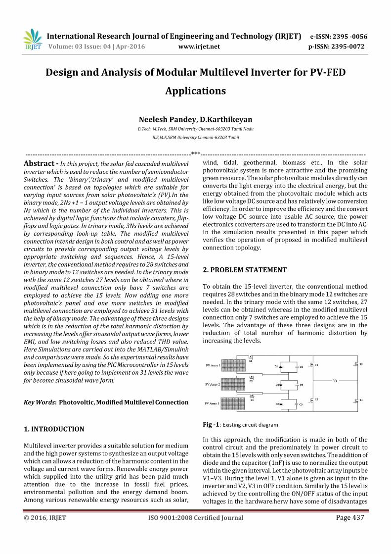
Fig -1: Existing circuit diagram
In this approach, the modification is made in both of the control circuit and the predominately in power circuit to obtain the 15 levels with only seven switches. The addition of diode and the capacitor (1nF) is use to normalize the output within the given interval. Let the photovoltaic array inputs be V1–V3. During the level 1, V1 alone is given as input to the inverter and V2, V3 in OFF condition. Similarly the 15 level is achieved by the controlling the ON/OFF status of the input voltages in the hardware.herw have some of disadvantages
International Research Journal of Engineering and Technology (IRJET) e-ISSN: 2395 -0056
Volume: 03 Issue: 04 | Apr-2016 www.irjet.net p-ISSN: 2395-0072
© 2016, IRJET ISO 9001:2008 Certified Journal Page 438
like low power quality, much higher harmonics, poor efficiency
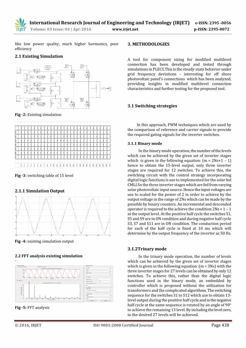
2.1 Existing Simulation
Fig -2: Existing simulation
0 1 2 3 4 5 6 7 6 5 4 3 2 1 0 -1 -2 -3 -4 -5 -6 -7 -6 -5 -4 -3 -2 -1
S1 0 1 0 1 0 1 0 1 0 1 0 1 0 1 0 1 0 1 0 1 0 1 0 1 0 1 0 1
S2 0 0 1 1 0 0 1 1 1 0 0 1 1 0 0 0 1 1 0 0 1 1 1 0 0 1 1 0
S3 0 0 0 0 1 1 1 1 1 1 1 0 0 0 0 0 0 0 1 1 1 1 1 1 1 0 0 0
S4 0 1 1 1 1 1 1 1 1 1 1 1 1 1 0 0 0 0 0 0 0 0 0 0 0 0 0 0
S5 0 0 0 0 0 0 0 0 0 0 0 0 0 0 0 1 1 1 1 1 1 1 1 1 1 1 1 1
S6 0 0 0 0 0 0 0 0 0 0 0 0 0 0 0 1 1 1 1 1 1 1 1 1 1 1 1 1
S7 0 1 1 1 1 1 1 1 1 1 1 1 1 1 0 0 0 0 0 0 0 0 0 0 0 0 0 0
0 1 2 3 4 5 6 7 8 9 10 11 12 13 14 15 16 17 18 19 20 21 22 23 24 25 26 27 Fig -3: switching table of 15 level
2.1.1 Simulation Output
Fig -4: existing simulation output
2.2 FFT analysis existing simulation
Fig -5: FFT analysis
3. METHODOLOGIES
A tool for component sizing for modified multilevel connection has been developed and tested through simulations in PLECS.This is the steady-state behavior under grid frequency deviations - interesting for off shore photovoltaic panel’s connections which has been analyzed, providing insights in modified multilevel connection characteristics and further testing for the proposed tool.
3.1 Switching strategies
In this approach, PWM techniques which are used by the comparison of reference and carrier signals to provide the required gating signals for the inverter switches.
3.1.1 Binary mode
In the binary mode operation, the number of the levels which can be achieved by the given set of inverter stages which is given in the following equation: (m = 2Ns+1 – 1) hence to obtain the 15-level output, only three inverter stages are required for 12 switches. To achieve this, the switching circuit with the control strategy incorporating digital logic functions is use to implemented for the solar fed CMLI.So the three inverter stages which are fed from varying solar photovoltaic input source. Hence the input voltages are use to scaled for the power of 2 in order to achieve by the output voltage in the range of 2Ns which can be made by the possible by binary counters. An incremental and descended operator is required to the achieve the condition 2Ns + 1 − 1 at the output level. At the positive half cycle the switches S1, S5 and S9 are in ON condition and during negative half cycle S3, S7 and S11 are in ON condition. The conduction period for each of the half cycle is fixed at 10 ms which will determine by the output frequency of the inverter as 50 Hz.
3.1.2Trinary mode
In the trinary mode operation, the number of levels which can be achieved by the given set of inverter stages which is given in the following equation :(m = 3Ns) with the three inverter stages for 27 levels can be obtained by only 12 switches. To achieve this, rather than the digital logic functions used in the binary mode, an embedded by controller which is proposed without the utilization for transformers and the complicated algorithms. The switching sequence for the switches S1 to S12 which use to obtain 13-level output during the positive half cycle and in the negative half cycle at the same sequence is rotated by an angle of 90° to achieve the remaining 13 level. By including the level zero, to the desired 27 levels will be achieved.
International Research Journal of Engineering and Technology (IRJET) e-ISSN: 2395 -0056
Volume: 03 Issue: 04 | Apr-2016 www.irjet.net p-ISSN: 2395-0072
© 2016, IRJET ISO 9001:2008 Certified Journal Page 439
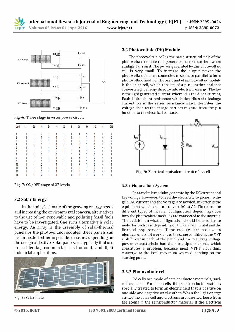
Fig -6: Three stage inverter power circuit
Fig -7: ON/OFF stage of 27 levels
3.2 Solar Energy
In the today's climate of the growing energy needs and increasing the environmental concern, alternatives to the use of non-renewable and polluting fossil fuels have to be investigated. One such alternative is solar energy. An array is the assembly of solar-thermal panels or the photovoltaic modules; these panels can be connected either in parallel or series depending on the design objective. Solar panels are typically find use in residential, commercial, institutional, and light industrial applications.
Fig -8: Solar Plate
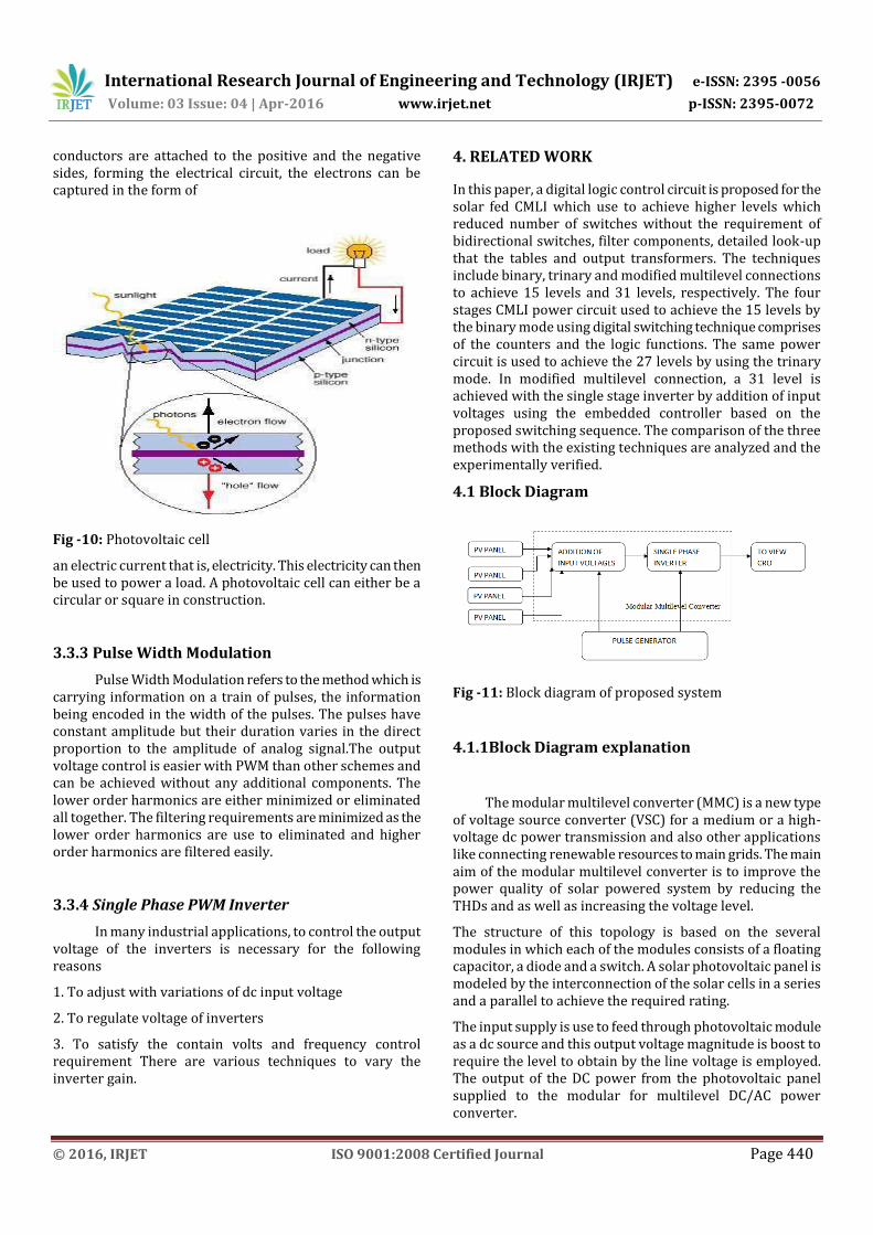
3.3 Photovoltaic (PV) Module
The photovoltaic cell is the basic structural unit of the photovoltaic module that generates current carriers when sunlight falls on it. The power generated by this photovoltaic cell is very small. To increase the output power the photovoltaic cells are connected in series or parallel to form photovoltaic module. The basic unit of a photovoltaic module is the solar cell, which consists of a p-n junction and that converts light energy directly into electrical energy. The Ipv is the light generated current, where Id is the diode current, Rash is the shunt resistance which describes the leakage current, Rs is the series resistance which describes the voltage drop as the charge carriers migrate from the p-n junction to the electrical contacts.
Fig -9: Electrical equivalent circuit of pv cell
3.3.1 Photovoltaic System
Photovoltaic modules generate by the DC current and the voltage. However, to feed the electricity to generate the grid, AC current and the voltage are needed. Inverter is the equipment which used to convert DC to AC. There are the different types of inverter configuration depending upon how the photovoltaic modules are connected to the inverter. The decision on what configuration should be used has to make for each case depending on the environmental and the financial requirements. If the modules are not use to identical or do not work under the same conditions, the MPP is different in each of the panel and the resulting voltage power characteristic has their multiple maxima, which constitutes a problem, because most MPPT algorithms converge to the local maximum which depending on the starting point.
3.3.2 Photovoltaic cell
PV cells are made of semiconductor materials, such call as silicon. For solar cells, thin semiconductor water is specially treated to form an electric field that is positive on one side and negative on the other. When the light energy strikes the solar cell and electrons are knocked loose from the atoms in the semiconductor material. If the electrical
International Research Journal of Engineering and Technology (IRJET) e-ISSN: 2395 -0056
Volume: 03 Issue: 04 | Apr-2016 www.irjet.net p-ISSN: 2395-0072
© 2016, IRJET ISO 9001:2008 Certified Journal Page 440
conductors are attached to the positive and the negative sides, forming the electrical circuit, the electrons can be captured in the form of
Fig -10: Photovoltaic cell
an electric current that is, electricity. This electricity can then be used to power a load. A photovoltaic cell can either be a circular or square in construction.
3.3.3 Pulse Width Modulation
Pulse Width Modulation refers to the method which is carrying information on a train of pulses, the information being encoded in the width of the pulses. The pulses have constant amplitude but their duration varies in the direct proportion to the amplitude of analog signal.The output voltage control is easier with PWM than other schemes and can be achieved without any additional components. The lower order harmonics are either minimized or eliminated all together. The filtering requirements are minimized as the lower order harmonics are use to eliminated and higher order harmonics are filtered easily.
3.3.4 Single Phase PWM Inverter
In many industrial applications, to control the output voltage of the inverters is necessary for the following reasons
1. To adjust with variations of dc input voltage
2. To regulate voltage of inverters
3. To satisfy the contain volts and frequency control requirement There are various techniques to vary the inverter gain.
4. RELATED WORK
In this paper, a digital logic control circuit is proposed for the solar fed CMLI which use to achieve higher levels which reduced number of switches without the requirement of bidirectional switches, filter components, detailed look-up that the tables and output transformers. The techniques include binary, trinary and modified multilevel connections to achieve 15 levels and 31 levels, respectively. The four stages CMLI power circuit used to achieve the 15 levels by the binary mode using digital switching technique comprises of the counters and the logic functions. The same power circuit is used to achieve the 27 levels by using the trinary mode. In modified multilevel connection, a 31 level is achieved with the single stage inverter by addition of input voltages using the embedded controller based on the proposed switching sequence. The comparison of the three methods with the existing techniques are analyzed and the experimentally verified.
4.1 Block Diagram
Fig -11: Block diagram of proposed system
4.1.1Block Diagram explanation
The modular multilevel converter (MMC) is a new type of voltage source converter (VSC) for a medium or a high-voltage dc power transmission and also other applications like connecting renewable resources to main grids. The main aim of the modular multilevel converter is to improve the power quality of solar powered system by reducing the THDs and as well as increasing the voltage level.
The structure of this topology is based on the several modules in which each of the modules consists of a floating capacitor, a diode and a switch. A solar photovoltaic panel is modeled by the interconnection of the solar cells in a series and a parallel to achieve the required rating.
The input supply is use to feed through photovoltaic module as a dc source and this output voltage magnitude is boost to require the level to obtain by the line voltage is employed. The output of the DC power from the photovoltaic panel supplied to the modular for multilevel DC/AC power converter.
International Research Journal of Engineering and Technology (IRJET) e-ISSN: 2395 -0056
Volume: 03 Issue: 04 | Apr-2016 www.irjet.net p-ISSN: 2395-0072
© 2016, IRJET ISO 9001:2008 Certified Journal Page 441
A Pulse Generator generates the control signals or firing the pulse for the inverter to maintain the level of output. Some applications are: industrial machines, automobiles medical equipment, household appliances, airplanes, high power applications.
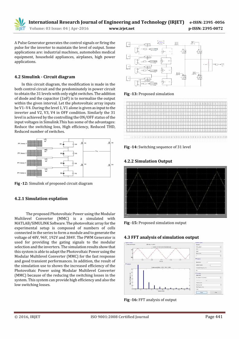
4.2 Simulink - Circuit diagram
In this circuit diagram, the modification is made in the both control circuit and the predominately in power circuit to obtain the 31 levels with only eight switches. The addition of diode and the capacitor (1nF) is to normalize the output within the given interval. Let the photovoltaic array inputs be V1–V4. During the level 1, V1 alone is given as input to the inverter and V2, V3, V4 in OFF condition. Similarly the 31 level is achieved by the controlling the ON/OFF status of the input voltages in Simulink.This has some of the advantages: Reduce the switching loss, High efficiency, Reduced THD, Reduced number of switches.
Fig -12: Simulink of proposed circuit diagram
4.2.1 Simulation explation
The proposed Photovoltaic Power using the Modular Multilevel Converter (MMC) is a simulated with MATLAB/SIMULINK Software. The photovoltaic array for the experimental setup is composed of numbers of cells connected in the series to form a module and to generate the voltage of 48V, 96V, 192V and 384V. The PWM Generator is used for providing the gating signals to the modular selection and the inverters. The simulation results show that this system is able to adapt the Photovoltaic Power using the Modular Multilevel Converter (MMC) for the fast response and good transient performances. In addition, the result of the simulation use to shows the increased efficiency of the Photovoltaic Power using Modular Multilevel Converter (MMC) because of the reducing the switching losses in the system. This system can provide high efficiency and also the low switching losses.
Fig -13: Proposed simulation
0 1 2 3 4 5 6 7 8 9 10 11 12 13 14 15 14 13 12 11 10 9 8 7 6 5 4 3 2 1 0 -1 -2 -3 -4 -5 -6 -7 -8 -9 -10 -11 -12 -13 -14 -15 -14 -13 -12 -11 -10 -9 -8 -7 -6 -5 -4 -3 -2 -1
S1 0 1 0 1 0 1 0 1 0 1 0 1 0 1 0 1 0 1 0 1 0 1 0 1 0 1 0 1 0 1 0 1 0 1 0 1 0 1 0 1 0 1 0 1 0 1 0 1 0 1 0 1 0 1 0 1 0 1 0 1
S2 0 0 1 1 0 0 1 1 0 0 1 1 0 0 1 1 1 0 0 1 1 0 0 1 1 0 0 1 1 0 0 0 1 1 0 0 1 1 0 0 1 1 0 0 1 1 1 0 0 1 1 0 0 1 1 0 0 1 1 0
S3 0 0 0 0 1 1 1 1 0 0 0 0 1 1 1 1 1 1 1 0 0 0 0 1 1 1 1 0 0 0 0 0 0 0 1 1 1 1 0 0 0 0 1 1 1 1 1 1 1 0 0 0 0 1 1 1 1 0 0 0
S4 0 0 0 0 0 0 0 0 1 1 1 1 1 1 1 1 1 1 1 1 1 1 1 0 0 0 0 0 0 0 0 0 0 0 0 0 0 0 1 1 1 1 1 1 1 1 1 1 1 1 1 1 1 0 0 0 0 0 0 0
S5 0 1 1 1 1 1 1 1 1 1 1 1 1 1 1 1 1 1 1 1 1 1 1 1 1 1 1 1 1 1 0 0 0 0 0 0 0 0 0 0 0 0 0 0 0 0 0 0 0 0 0 0 0 0 0 0 0 0 0 0
S6 0 0 0 0 0 0 0 0 0 0 0 0 0 0 0 0 0 0 0 0 0 0 0 0 0 0 0 0 0 0 0 1 1 1 1 1 1 1 1 1 1 1 1 1 1 1 1 1 1 1 1 1 1 1 1 1 1 1 1 1
S7 0 0 0 0 0 0 0 0 0 0 0 0 0 0 0 0 0 0 0 0 0 0 0 0 0 0 0 0 0 0 0 1 1 1 1 1 1 1 1 1 1 1 1 1 1 1 1 1 1 1 1 1 1 1 1 1 1 1 1 1
S8 0 1 1 1 1 1 1 1 1 1 1 1 1 1 1 1 1 1 1 1 1 1 1 1 1 1 1 1 1 1 0 0 0 0 0 0 0 0 0 0 0 0 0 0 0 0 0 0 0 0 0 0 0 0 0 0 0 0 0 0
1 2 3 4 5 6 7 8 9 10 11 12 13 14 15 16 17 18 19 20 21 22 23 24 25 26 27 28 29 30 31 32 33 34 35 36 37 38 39 40 41 42 43 44 45 46 47 48 49 50 51 52 53 54 55 56 57 58 59
Fig -14: Switching sequence of 31 level
4.2.2 Simulation Output
Fig -15: Proposed simulation output
4.3 FFT analysis of simulation output
Fig -16: FFT analysis of output
International Research Journal of Engineering and Technology (IRJET) e-ISSN: 2395 -0056
Volume: 03 Issue: 04 | Apr-2016 www.irjet.net p-ISSN: 2395-0072
© 2016, IRJET ISO 9001:2008 Certified Journal Page 442
5. CONCLUSION
A 31 level is obtained by MMC by adding one more switch and one more dc sources in solar fed modular multilevel inverter for the elimination of certain harmonic orders, reduced switching losses; reduced number of switches are developed and compared with 15 levels MMC for the power quality improvement. The advantages of this method include simple computational algorithm gives high efficiency, reduced total harmonic distortion and minimum requirement of filters. Moreover, this technique can be implemented in both standalone and grid interacted PV systems.
ACKNOWLEDGEMENT
The authors acknowledge and thank the Department of Science and Technology (Government of India) for sanctioning the research grant for the project titled, ‘Design and Development of Multilevel Inverters for Power Quality Improvement in Renewable Energy Sources’ (Ref.No.DST/ TSG/NTS/2009/98) under Technology Systems Development Scheme for completing this work.
REFERENCES [1] Rahim, N.A., Selvaraj, J.: ‘Multistring five-level inverter
with novel PWM control scheme for PV application’, IEEE Trans. Ind. Electron.,2010, 57, (6), pp. 2111–2123
[2] Selvaraj, J., Rahim, N.A.: ‘Multilevel inverter for grid-connected PV system employing digital PI controller’, IEEE Trans. Ind. Electron.,2009, 56, (1), pp. 149–158R. Nicole, “Title of paper with only first word capitalized,” J. Name Stand. Abbrev., in press.
[3] Rahim, N.A., Chaniago, K., Selvaraj, J.: ‘Single-phase seven-level grid-connected inverter for photovoltaic system’, IEEE Trans. Ind.Electron., 2011, 58, (6), pp. 2435–2443
[4] Barbosa, P.G., Braga, H.A.C., do Carmo Barbosa Rodrigues, M.,Teixeira, E.C.: ‘Boost current multilevel inverter and its application on single-phase grid-connected photovoltaic systems’, IEEE Trans.Power Electron., 2006, 21, (4), pp. 1116–1124
[5] Villanueva, E., Correa, P., Rodríguez, J., Pacas, M.:’Control of a single-phase cascaded H-bridge multilevel inverter for grid-connected photovoltaic systems’, IEEE Trans. Ind. Electron., 2009, 56, (11),pp. 4399–4406
[6] Kangarlu, M.F., Babaei, E.: ‘A generalized cascaded multilevel inverter using series connection of sub multilevel inverters’,
[7] Nami, A., Zare, F., Ghosh, A., Blaabjerg, F.: ‘A hybrid cascade converter topology with series-connected symmetrical and asymmetrical diode-clamped H-bridge
cells’, IEEE Trans. Power Electron., 2011, 26, (1), pp. 51–65
[8] Mondal, G., Gopakumar, K., Tekwani, P.N., Levi, E.: ‘A reduced switch-count five-level inverter with common-mode voltage elimination for an open-end winding induction motor drive,IEEE Trans. Ind. Electron., 2007, 54, (4), pp. 2344–2351
[9] Babaei, E.:Optimal topologies for cascaded sub-multilevel converters’,J. Power Electron., 2010, 10, (3), pp. 251–261
[10] Babaei, E.: ‘A cascade multilevel converter topology with reduced number of switches’, IEEE Trans. Power Electron., 2008, 23, (6),pp. 2657–2664
[11] Babaei, E., Hosseini, S.H., Gharehpetian, G.B., Haque, M.T., Sabahi,M.: ‘Reduction of DC voltage sources and switches in asymmetrical multilevel converters using a novel topology’, J. Electr. Power Syst. Res., 2007, 77, (8), pp. 1073–1085
[12] Dixon, J., Pereda, J., Castillo, C., Bosch, S.:Asymmetrical multilevel inverter for traction drives using only one DC supply’, IEEE Trans. Veh. Tech., 2010, 59, (8), pp. 3736–3743
[13] Rotella, M., Penailillo, G., Pereda, J., Dixon, J.: ‘PWM method to eliminate power sources in a non-redundant 27-level inverter for machine drive applications’, IEEE Trans. Ind. Electron., 2009, 56,
[14] Dixon, J., Mor´an, L.: ‘High-level multistep inverter optimization using minimum number of power transistors, 2006, 21, (2), pp. 330–337
[15] Kang, F.-S., Park, S.-J., Lee, M.H., Kim, C.-U.: ‘An efficient multilevel-synthesis approach and its application to a 27-level inverter’, IEEE Trans. Ind. Electron., 2005, 52,(6), pp. 1600–1606
[16] Dixon, J., Bretón, A.A., Ríos, F.E., Rodríguez, J., Pontt, J., Pérez, M.A.:High-power machine drive, using nonredundant 27-level inverters and active front end rectifiers’, IEEE Trans. Power Electron., 2007, 22, pp. 2527–2533
Mr. Neelesh Pandey Received The B.Tech. Degree In Electrical And Electronic Engineering From The Vel Tech Dr. RR and Dr. Sr Technical university Chennai, Tamil Nadu,India. In 2010-14, He is pursuing The M.Tech In Power electronics and drive From The SRM University, Chennai, Tamil Nadu.
Mr. D.Karthikeyeyan is currently working as Assistant Professor in the department of EEE at SRM University Chennai; he completed his B.E in 2009 at Anna university Chennai and M.Tech in 2013 at SRM University Chennai.


![A Review of Multilevel Inverter Topology and Control ... Review of Multilevel Inverter Topology and Control Techniques . ... dv/dt) [1], multilevel inverter has ... configuration has](https://img.pdfslide.net/doc/110x75/5ae02cdf7f8b9a6e5c8d10cd/a-review-of-multilevel-inverter-topology-and-control-review-of-multilevel-inverter.jpg)