Embed Size (px)
Citation preview
Design and Analysis of Submarine Radome
C. Satya Sandeep1, U. Shiva Prasad 2, R. Suresh 3, A. Rathan 4, G. Sravanthi 5,
D. Govardhan 6
1, 2,3,4,5 Assistant professor in Department of Aeronautical Engineering, Institute of Aeronautical Engineering
Hyderabad, Telangana, India 500043.
6 Head of the Department - Department of Aeronautical Engineering, Institute of Aeronautical Engineering
Hyderabad, Telangana, India 500043.
Abstract. Radomes are the electromagnetic windows that protect microwave sub-systems from the environmental
effects. The major requirement of radome is its transparency to microwaves and for most of the cases mechanical
properties are also equally important. Radome for underwater applications has to withstand high water pressure of the
order of 45 bars. Composite materials owing to their high strength to weight ratio, high stiffness and better corrosion
resistance are potential source for under water applications. The concept of 'tailoring' the material properties to suit
the radome is obtained by selecting proper reinforcement, resin matrix and their compositions. The mechanical
properties of composite material, evaluated by testing specimens as per ASTM standards, are utilized in designing the
radome. The modulus properties calculated using classical theories of composite materials and compared with test
results. ANSYS a Finite Element software package used to analyse the problem. As the cross sectional thickness of
radome varies, the complexity in fabrication is overcome by adopting matched die techniques. The radome design and
finite element analysis validation concluded by conducting the pressure test on radome. On the design a modal analysis
is also carried to check for the natural frequency, So that resonance does not occur if the natural frequency of the
radome coincides with the excitation frequency of the submarine Clinical information system (CIS) for UNRWA is a
computerized distributed application that used in clinics which follows the United Nations Relief and Works Agency
(UNRWA) to manage the clinical requirements and services.
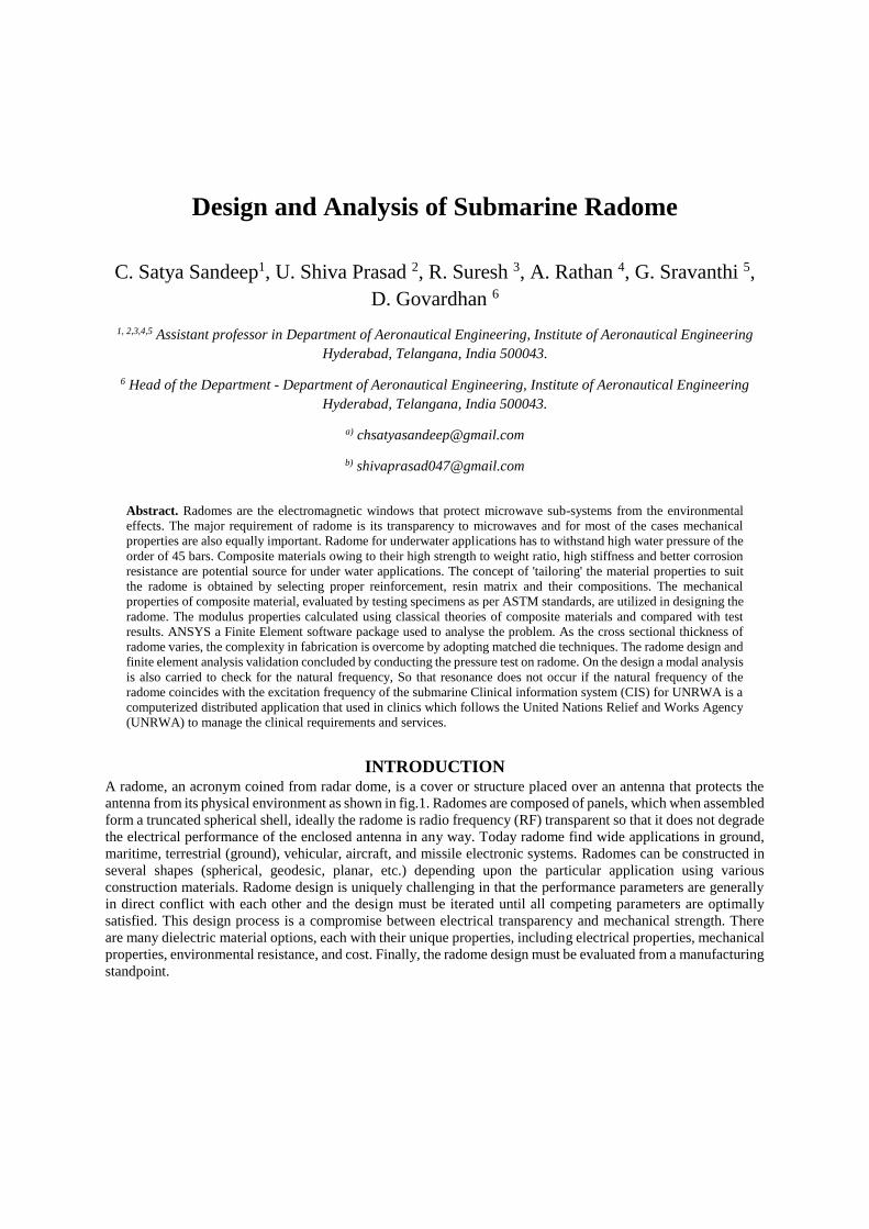
INTRODUCTION A radome, an acronym coined from radar dome, is a cover or structure placed over an antenna that protects the
antenna from its physical environment as shown in fig.1. Radomes are composed of panels, which when assembled
form a truncated spherical shell, ideally the radome is radio frequency (RF) transparent so that it does not degrade
the electrical performance of the enclosed antenna in any way. Today radome find wide applications in ground,
maritime, terrestrial (ground), vehicular, aircraft, and missile electronic systems. Radomes can be constructed in
several shapes (spherical, geodesic, planar, etc.) depending upon the particular application using various
construction materials. Radome design is uniquely challenging in that the performance parameters are generally
in direct conflict with each other and the design must be iterated until all competing parameters are optimally
satisfied. This design process is a compromise between electrical transparency and mechanical strength. There
are many dielectric material options, each with their unique properties, including electrical properties, mechanical
properties, environmental resistance, and cost. Finally, the radome design must be evaluated from a manufacturing
standpoint.
FIGURE. 1 Radome with antenna
The increased power of modern computers allows a radome designer to evaluate designs in a manner that was not
previously possible, such as designs with frequency selective materials, low observable treatments, or meta-
materials. In analysing radome electrical performance, it is important to evaluate the electrical properties of
possible radome wall materials at various wavelengths. The primary electrical properties of candidate materials
are the relative dielectric constant and the loss tangent of the candidate materials at the operational frequencies of
the radome. The structural (aeromechanical) and environmental requirements determine other parameters for a
candidate radome material and include Mechanical properties, such as flexural moduli, strength, and hardness;
Material density; Water absorption; Rain erosion (particle impact) resistance; The variation of both the mechanical
and electrical parameters of the material due to temperature variations[8]. Common radome shapes include, but
are not limited to the following Hemisphere; Secant ogive; Tangent ogive; from an electrical viewpoint, a
hemisphere is most desirable because of its very small incidence angles resulting in small electrical degradations
[1].
The radome protects the installation from the deteriorating effects of environment and extends the durability of
antenna and other equipment. The overall performance of the antenna will be increased with the use of radome.
A radome helps to have overall economy and weight reduction and permits the air borne antenna to function with
good efficiency under high head of the water over the submarine.
The selection of a manufacturing method for a given Radome design may be based on a number of factors
including the Radome performance requirements and the materials of construction. For example selection of a
fabrication method for a Radome often starts by the consideration of Vacuum bag or Autoclave moulding using
glass fabric reinforcement. Frequency requirements for maintaining uniform electrical properties in the Radome
wall might eliminate the less expensive fabrication methods and dictate a filament winding approach whereby this
control is more readily accomplished.
SIMULATION METHODOLOGY It has been conceived aiming at providing reader with the under water bodies applications with the essentials of
numerical techniques developed for characterizing the dynamic behaviour of structural systems. Finite element
analysis has several methods for solving given problems. The direct approach is only able to solve elementary
problems, which is based on the stiffness matrix for structural analysis. This method is even though effective for
elementary problems, can be utilized to solve more complex one. This is accomplished by breaking down the
complex geometry into elementary problems, with emphasis being placed on nodes that intersect. By utilizing this
concept the designer/ engineer is able to determine a stiffness matrix for the give part of that structure. Then by
combining the matrices of the parts, the stiffness of the entire structure can be determined. This method has
become known as the direct stiffness method and was the first method utilized for solving finite analysis. In this
work, environmental and energy-related aspects, have given the subject of concern, which are frequently in
relation with structural dynamics. The technique of modal analysis is like, the equations of motion (EOM), which
are originally expressed in physical coordinates, are transformed to modal coordinates using the eigenvalues and
eigenvectors by solving the undammed frequency Eigen problem[2]. The structure with of the radome is analysed
by discretized with a number of elements and then assembled at nodes. The elements of different type and shape
with complex loads and boundary conditions have be used simultaneously using FEM. As a magnitude of the past
works, it was noted that in order to accurately predict the physical behaviours of the structure under the influence
of pressure loading for under water bodies structural integrity need a detailed three-dimensional model is
desirable[4], which fully includes the pressure and shear forces acting on mating parts and pretension effect to tie.
However, for a large complex structure such as a marine engine, the detailed modelling of the complete model is
difficult because of restriction of the problem size and computational cost to analyse the entire structure.
Therefore, in this paper, in order to investigate a finite element modelling technique of the structure and modal
analysis the fluid analysis input is taken into consideration, two kinds of materials are introduced to known the
effective variation between the properties of structure; a solid model aerodynamic results are coupled with
structural model. Finally, the radome model proposed in this paper is adopted for a structural analysis of a large
marine radome connected to the external surface. All numerical simulations are carried out using implicit FEM
software package ANSYS.
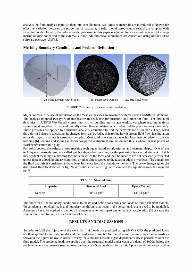
Meshing Boundary Conditions and Problem Definition
2a. Fluid Domain with Model 2b. Discretised Domain 2c. Structural Mesh
FIGURE. 2 Geometry of the model for simulation
Major concern in the use of simulations is the mesh as the cases are involved with materials and different domains.
The analysis required two types of meshes are in need, one for structural and other for fluid. The structural
dynamics in ANSYS Workbench comes into its own building multi-stage workflows, where separate analysis
systems work together. In this work initially a fluid flow simulation is carried to find the pressure on radome body.
These pressures are applied to a structural analysis simulation to find the performance of the parts. Then, when
the deformed shape is calculated, its changed form can be fed back in to find how it affects fluid flow. In simulation
terms this type of analysis is extremely complex. Most fluid flow simulation technology uses completely different
meshing [6], loading and solving methods compared to structural simulation and this is where the true power of
Workbench comes into play.
For solid bodies, the software uses meshing techniques based on algorithms and element shape. One of the
technique extensively used are called patch independent meshing for the part using tetrahedral element. Patch
independent meshing is a meshing technique in which the faces and their boundaries are not necessarily respected
unless there is a load, boundary condition, or other object scoped to the faces or edges or vertices. The domain for
the fluid analysis is considered to have least influence from the domain to the body. The below images gives the
discretised fluid field shown in fig. 2b and solid structure in fig. 2c to evaluate the equations over the required
fields.
TABLE 1. Material Data
Properties Structural Steel Epoxy Carbon
Density 7850 kg/m3 1490 kg/m3
The function of the boundary conditions is to create and define constraints and loads on finite Element models.
To simulate a model, all loads and boundary conditions that occur in the actual loads event need to be modelled.
A pressure has to be applied to the body in a manner as to not impart any unrealistic acceleration [3] or cause the
simulation to run for an extended amount of time.
RESULTS AND DISCUSSIONS
In order to fulfil the objective of the work first fluid loads are predicted using ANSYS CFX the predicted loads
are then applied to the static model and the results are presented for the different materials under same loads as
shown in the figures below. In order to verify the simulation results a grid dependent study is performed over the
fluid model. The predicted loads are applied over the structural model under water at a depth of 1000m below the
sea level where the pressure resulted over the body is 9.5 bar as shown in fig 3 & 4 pressure at the design used in
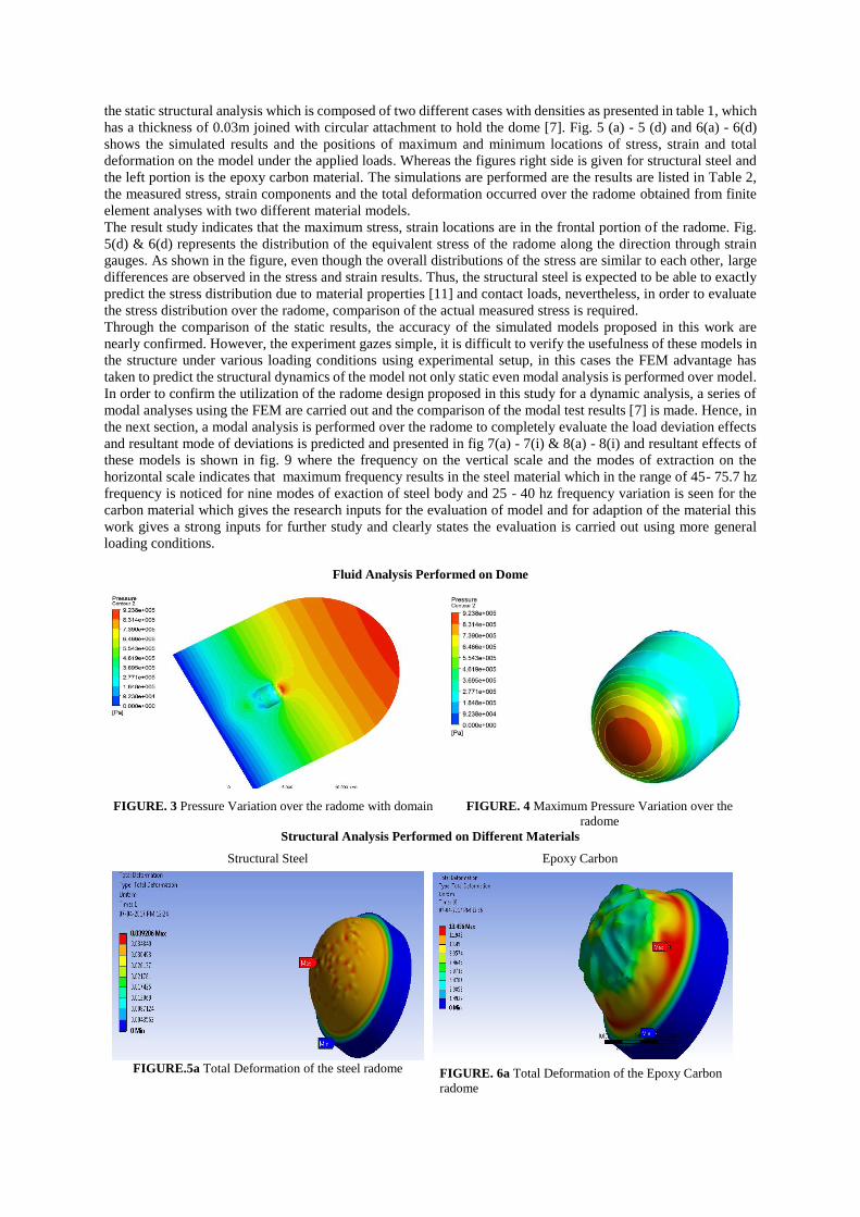
the static structural analysis which is composed of two different cases with densities as presented in table 1, which
has a thickness of 0.03m joined with circular attachment to hold the dome [7]. Fig. 5 (a) - 5 (d) and 6(a) - 6(d)
shows the simulated results and the positions of maximum and minimum locations of stress, strain and total
deformation on the model under the applied loads. Whereas the figures right side is given for structural steel and
the left portion is the epoxy carbon material. The simulations are performed are the results are listed in Table 2,
the measured stress, strain components and the total deformation occurred over the radome obtained from finite
element analyses with two different material models.
The result study indicates that the maximum stress, strain locations are in the frontal portion of the radome. Fig.
5(d) & 6(d) represents the distribution of the equivalent stress of the radome along the direction through strain
gauges. As shown in the figure, even though the overall distributions of the stress are similar to each other, large
differences are observed in the stress and strain results. Thus, the structural steel is expected to be able to exactly
predict the stress distribution due to material properties [11] and contact loads, nevertheless, in order to evaluate
the stress distribution over the radome, comparison of the actual measured stress is required.
Through the comparison of the static results, the accuracy of the simulated models proposed in this work are
nearly confirmed. However, the experiment gazes simple, it is difficult to verify the usefulness of these models in
the structure under various loading conditions using experimental setup, in this cases the FEM advantage has
taken to predict the structural dynamics of the model not only static even modal analysis is performed over model.
In order to confirm the utilization of the radome design proposed in this study for a dynamic analysis, a series of
modal analyses using the FEM are carried out and the comparison of the modal test results [7] is made. Hence, in
the next section, a modal analysis is performed over the radome to completely evaluate the load deviation effects
and resultant mode of deviations is predicted and presented in fig 7(a) - 7(i) & 8(a) - 8(i) and resultant effects of
these models is shown in fig. 9 where the frequency on the vertical scale and the modes of extraction on the
horizontal scale indicates that maximum frequency results in the steel material which in the range of 45- 75.7 hz
frequency is noticed for nine modes of exaction of steel body and 25 - 40 hz frequency variation is seen for the
carbon material which gives the research inputs for the evaluation of model and for adaption of the material this
work gives a strong inputs for further study and clearly states the evaluation is carried out using more general
loading conditions.
Fluid Analysis Performed on Dome
FIGURE. 3 Pressure Variation over the radome with domain
FIGURE. 4 Maximum Pressure Variation over the
radome
Structural Analysis Performed on Different Materials
Structural Steel Epoxy Carbon
FIGURE.5a Total Deformation of the steel radome FIGURE. 6a Total Deformation of the Epoxy Carbon
radome
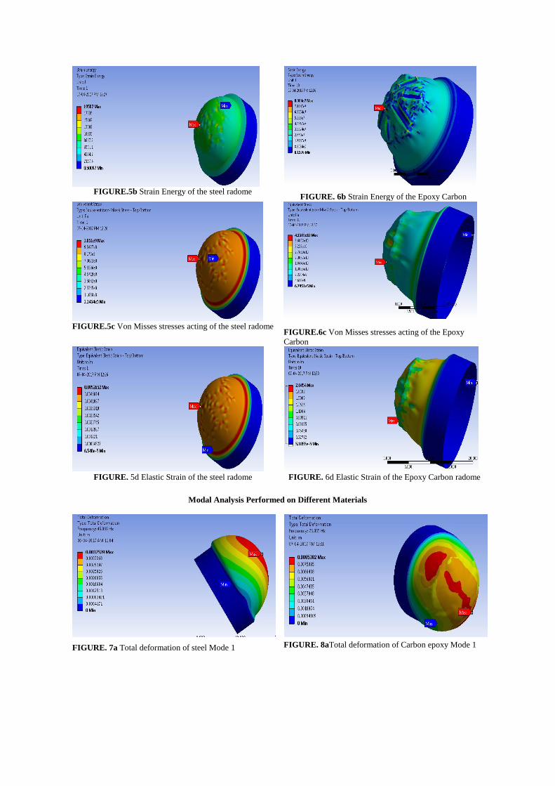
FIGURE.5b Strain Energy of the steel radome
FIGURE. 6b Strain Energy of the Epoxy Carbon
FIGURE.5c Von Misses stresses acting of the steel radome
FIGURE.6c Von Misses stresses acting of the Epoxy
Carbon
FIGURE. 5d Elastic Strain of the steel radome FIGURE. 6d Elastic Strain of the Epoxy Carbon radome
Modal Analysis Performed on Different Materials
FIGURE. 7a Total deformation of steel Mode 1
FIGURE. 8aTotal deformation of Carbon epoxy Mode 1
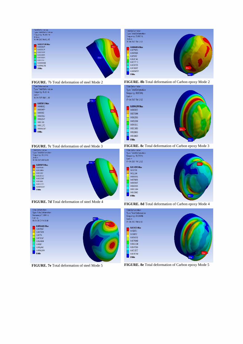
FIGURE. 7b Total deformation of steel Mode 2
FIGURE. 8b Total deformation of Carbon epoxy Mode 2
FIGURE. 7c Total deformation of steel Mode 3
FIGURE. 8c Total deformation of Carbon epoxy Mode 3
FIGURE. 7d Total deformation of steel Mode 4
FIGURE. 8d Total deformation of Carbon epoxy Mode 4
FIGURE. 7e Total deformation of steel Mode 5
FIGURE. 8e Total deformation of Carbon epoxy Mode 5
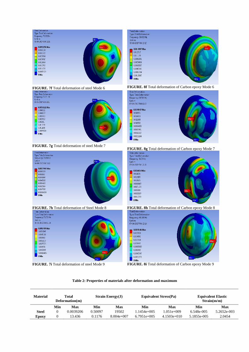
FIGURE. 7f Total deformation of steel Mode 6
FIGURE. 8f Total deformation of Carbon epoxy Mode 6
FIGURE. 7g Total deformation of steel Mode 7
FIGURE. 8g Total deformation of Carbon epoxy Mode 7
FIGURE. 7h Total deformation of Steel Mode 8
FIGURE. 8h Total deformation of Carbon epoxy Mode 8
FIGURE. 7i Total deformation of steel Mode 9 FIGURE. 8i Total deformation of Carbon epoxy Mode 9
Table 2: Properties of materials after deformation and maximum
Material Total
Deformation(m)
Strain Energy(J) Equivalent Stress(Pa) Equivalent Elastic
Strain(m/m)
Min Max Min Max Min Max Min Max
Steel 0 0.0039206 0.50097 19502 1.1454e+005 1.051e+009 6.548e-005 5.2652e-003
Epoxy 0 13.436 0.1176 8.004e+007 6.7951e+005 4.1503e+010 5.1855e-005 2.0454
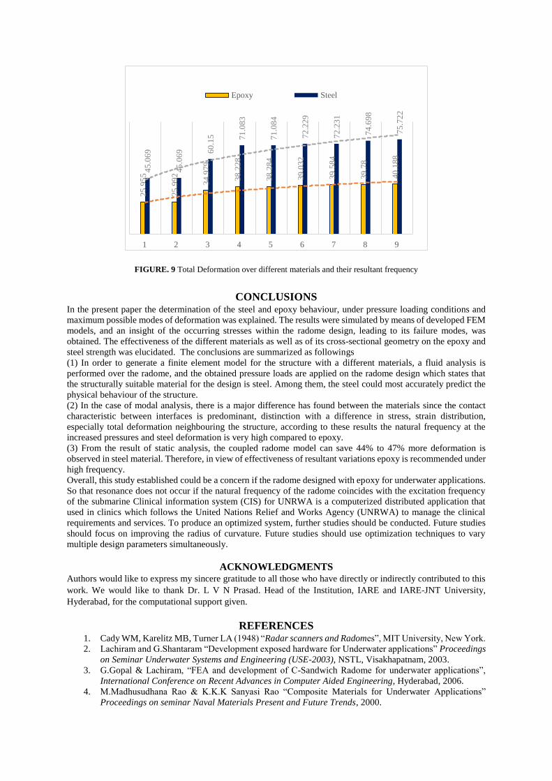
FIGURE. 9 Total Deformation over different materials and their resultant frequency
CONCLUSIONS In the present paper the determination of the steel and epoxy behaviour, under pressure loading conditions and
maximum possible modes of deformation was explained. The results were simulated by means of developed FEM
models, and an insight of the occurring stresses within the radome design, leading to its failure modes, was
obtained. The effectiveness of the different materials as well as of its cross-sectional geometry on the epoxy and
steel strength was elucidated. The conclusions are summarized as followings
(1) In order to generate a finite element model for the structure with a different materials, a fluid analysis is
performed over the radome, and the obtained pressure loads are applied on the radome design which states that
the structurally suitable material for the design is steel. Among them, the steel could most accurately predict the
physical behaviour of the structure.
(2) In the case of modal analysis, there is a major difference has found between the materials since the contact
characteristic between interfaces is predominant, distinction with a difference in stress, strain distribution,
especially total deformation neighbouring the structure, according to these results the natural frequency at the
increased pressures and steel deformation is very high compared to epoxy.
(3) From the result of static analysis, the coupled radome model can save 44% to 47% more deformation is
observed in steel material. Therefore, in view of effectiveness of resultant variations epoxy is recommended under
high frequency.
Overall, this study established could be a concern if the radome designed with epoxy for underwater applications.
So that resonance does not occur if the natural frequency of the radome coincides with the excitation frequency
of the submarine Clinical information system (CIS) for UNRWA is a computerized distributed application that
used in clinics which follows the United Nations Relief and Works Agency (UNRWA) to manage the clinical
requirements and services. To produce an optimized system, further studies should be conducted. Future studies
should focus on improving the radius of curvature. Future studies should use optimization techniques to vary
multiple design parameters simultaneously.
ACKNOWLEDGMENTS
Authors would like to express my sincere gratitude to all those who have directly or indirectly contributed to this
work. We would like to thank Dr. L V N Prasad. Head of the Institution, IARE and IARE-JNT University,
Hyderabad, for the computational support given.
REFERENCES 1. Cady WM, Karelitz MB, Turner LA (1948) “Radar scanners and Radomes”, MIT University, New York.
2. Lachiram and G.Shantaram “Development exposed hardware for Underwater applications” Proceedings
on Seminar Underwater Systems and Engineering (USE-2003), NSTL, Visakhapatnam, 2003.
3. G.Gopal & Lachiram, “FEA and development of C-Sandwich Radome for underwater applications”,
International Conference on Recent Advances in Computer Aided Engineering, Hyderabad, 2006.
4. M.Madhusudhana Rao & K.K.K Sanyasi Rao “Composite Materials for Underwater Applications”
Proceedings on seminar Naval Materials Present and Future Trends, 2000.
25
.95
5
25
.99
2
34
.97
9
38
.22
8
38
.28
4
39
.03
2
39
.58
4
39
.78
40
.18
8
45
.06
9
45
.06
9 60
.15 71
.08
3
71
.08
4
72
.22
9
72
.23
1
74
.69
8
75
.72
2
1 2 3 4 5 6 7 8 9
Epoxy Steel

5. N.S.Kumar, G.P.Agrawal & C.G.S.Sarma “Compatible Properties of Materials for Naval applications”
Proceedings on seminar Naval Materials Present and Future Trends, 2000.
6. Shiva P U, Sree V R “Three Dimensional Computational Analysis of Fluid Structure Interaction Over A
Finite Wing” International Conference on Mechanical and Aeronautical Engineering, pp 68-73, 2015.
7. Dr. Gates PJ & Lynn NM “Ships, Submarines & the Sea” Vol.2, Brassy’s (UK), 1990.
8. Bryan Harris “Engineering Composite Materials” 2nd edition, 1999.
9. Sun CT “Strength Analysis of Unidirectional Composite Laminates” Comprehensive Composite
Materials, Vol.1, Elsevier, 2000.
10. Robert M Jones “Mechanics of Composite Materials” McGraw-Hill Book Company, 1975.
11. Stephen P Timoshenko, James M Gere “Theory of Elastic Stability” 2nd edition, McGraw-Hill Book
Company, 1963.