Embed Size (px)
Citation preview

1
Design and Analysis of Three Phase Double
Sided Rotor Line Start Axial Flux Permanent
Magnet Synchronous Motor
Parth Patel
Master of Engineering (Electronics)
Flinders University
Supervisor: Dr. Amin Mahmoudi
October 2017
Submitted to the School of Computer Science, Engineering and Mathematics in the Faculty of
Science and Engineering in partial fulfilment of the requirements for the degree of Master
Engineering (Electronics).
2
Abstract
This thesis presents design, analysis and simulation of Line-start axil flux permanent magnet
synchronous motor (LSAFPMSM) with double sided rotor single stator slotted configuration.
Design of this type of motor used in many constant speed applications. This thesis presents
comparison between three phase double sided rotor line-start axial flux permanent magnet
synchronous motor (LSAFPMSM) with three phase Induction motor. Three axial flux motor
designs with different type of rotor with magnet and inductor bar configuration is designed.
These three designs are analysed with aluminium and copper material of inductor bar. The
design and analysis of the motor is performed in ANSYS Maxwell 3D software. The Finite
Element Analysis is used to analyse the motor performance and comparison of both motors.
Moreover, the steady state and dynamic performance of both motors are performed under no
load and under load condition. The characteristic of motor such as speed, torque, output power,
losses, induced voltage and magnetic flux density are studied. From the comparison of
LSAFPMSM and induction motor, the results confirm that speed of LSAFPMSM is stable at
synchronous speed while operation under loading conditions. The efficiency and power factor
of the LSAFPMSM is higher than induction motor. It is suitable to replace induction motor to
LSAFPMSM due to advantages of higher efficiency. The main disadvantage of the
LSAFPMSM is the higher cost of motor due to adding permanent magnets.

3
Declaration of Academic Integrity
‘I certify that this thesis does not incorporate without acknowledgment any material previously
submitted for a degree or diploma in any university; and that to the best of my knowledge and
belief it does not contain any material previously published or written by another person except
where due reference is made in the text.'
Parth Patel
Acknowledgements
I would like to acknowledge my family for supporting me throughout this project. I would also
like to specially acknowledge my supervisor, Dr. Amin Mahmoudi for providing me the
knowledge and help during this project.

4
Table of Contents
Abstract .................................................................................................................................. 2
Declaration of Academic Integrity ........................................................................................ 3
Acknowledgements ................................................................................................................ 3
List of Figures ........................................................................................................................ 7
List of Tables ....................................................................................................................... 11
Chapter 1: Introduction ........................................................................................................ 12
1.1 Background .................................................................................................................... 13
1.2 Problem statement .......................................................................................................... 15
1.3 Objectives ...................................................................................................................... 16
1.4 Methodology .................................................................................................................. 16
1.5 Limitations ..................................................................................................................... 16
1.6 Scope .............................................................................................................................. 17
1.7 Outline ........................................................................................................................... 17
Chapter 2: Literature Review ............................................................................................... 19
2.1 Introduction .................................................................................................................... 20
2.2 Induction Motor ............................................................................................................. 20
2.3 Axial Flux and Radial Flux Machine ............................................................................. 21
2.4 Line-start Axial Flux permanent magnet synchronous motor ....................................... 22
2.6 Gap Statement ................................................................................................................ 23
2.7 Contribution ................................................................................................................... 24
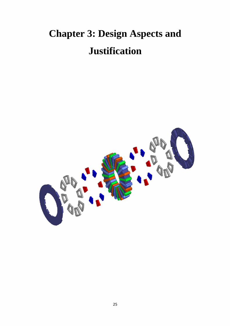
Chapter 3: Design Aspects and Justification ....................................................................... 25
3.1 Induction motor as a benchmark model ......................................................................... 26
3.1.1 Specification of induction motor ............................................................................ 28
3.1.2 Stator ....................................................................................................................... 28
3.1.3 Rotor ....................................................................................................................... 29

5
3.2 Design of Axial-flux machine ........................................................................................ 30
3.3 Machine arrangement of Axial-flux machine ................................................................ 31
3.4 Stator configuration for LSAFPMSM ........................................................................... 31
3.4.1 Windings of Stator .................................................................................................. 32
3.5 Rotor configuration for LSAFPMSM ............................................................................ 33
3.5.1 Design of Inductor bar ............................................................................................ 34
3.5.2 Shape of magnets .................................................................................................... 37
3.6 Electrical Steel ............................................................................................................... 38
Chapter 4: Method of Simulation ......................................................................................... 40
4.1 Simulation using Maxwell 3D FEA ............................................................................... 41
4.2 Magnetostatic Analysis .................................................................................................. 42
4.3 Magnetostatic Flux Linkage .......................................................................................... 48
4.4 Summary of Magnetostatic Analysis ............................................................................. 53
4.5 No load test analysis ...................................................................................................... 54
4.5.1 Induced voltage measurement................................................................................. 54
4.6 Transient analysis .......................................................................................................... 57
Chapter 5: Results and Discussion ....................................................................................... 58
5.1 Start-up of the Motor ..................................................................................................... 59
5.2 Winding current of Motors ............................................................................................ 70
5.3 Losses of the machine .................................................................................................... 73
5.4 Torque produced by Machine ........................................................................................ 79
5.5 Power Rating of machine ............................................................................................... 84
5.6 Efficiency of motor ........................................................................................................ 90
5.7 Power Factor .................................................................................................................. 91
Chapter 6: Conclusion and Future work ............................................................................. 94
6.1 Conclusion ..................................................................................................................... 95

6
6.2 Key Findings .................................................................................................................. 95
6.3 Future work .................................................................................................................... 96
References ............................................................................................................................ 97
Appendices ........................................................................................................................... 99
Appendix A: Mesh plots ...................................................................................................... 99
7
List of Figures
Fig 3.1 Exploded view of Induction motor 26
Fig 3.2 Different views of induction motor in 3-D 27
Fig 3.3 Design of slotted stator 29
Fig 3.4 Rotor with Inductor bars 29
Fig 3.5 Exploded view of Axial-flux synchronous motor 30
Fig 3.6 Different views of AFPMSM 30
Fig 3.7 Single stator, single rotor (SSSR) 31
Fig 3.8 Single stator, double rotor (SSDR) 31
Fig 3.9 Stator of LSAFPMSM with windings 32
Fig 3.10 Stator Dimension 32
Fig 3.11 3-phase winding diagram of stator 33
Fig 3.12 Rotor of LSAFPMSM with magnets 34
Fig 3.13 Rotor dimension 34
Fig 3.14 Inductor type 1 35
Fig 3.15 Inductor type 2 35
Fig 3.16 Inductor type 3 35
Fig 3.17 Inductor type 1 with rotor 35
Fig 3.18 Inductor type 2 with rotor 35
Fig 3.19 Inductor type 3 with rotor 36
Fig 3.20 Magnet shape 37
Fig 3.21: B-H curve for M19_29G electrical steel
Fig 4.1: Maxwell 3D model of motor
Fig 4.2: Magnetic flux density of motor at no load
Fig 4.3: Magnetic flux density of motor at 2Nm load
Fig 4.4: Magnetic flux vector of motor at no load
Fig 4.5: Magnetic flux vector of motor at 2Nm load
Fig 4.6: Magnetic flux linkage at no load
Fig 4.7: Magnetic flux linkage at 2Nm load
Fig 4.8: Induced voltage waveform of LSAFPMSM
38
41
43
44
46
47
50
53
56

8
Fig 5.1: Speed of induction motor at no load
Fig 5.2: Speed of LSAFPMSM type 1 Aluminium inductor at no load
Fig 5.3: Speed of LSAFPMSM type 1 Copper inductor at no load
Fig 5.4: Speed of LSAFPMSM type 2 Aluminium inductor at no load
Fig 5.5: Speed of LSAFPMSM type 2 Copper inductor at no load
Fig 5.6: Speed of LSAFPMSM type 3 Aluminium inductor at no load
Fig 5.7: Speed of LSAFPMSM type 3 Copper inductor at no load
Fig 5.8: Speed of induction motor at 2Nm load
Fig 5.9: Speed of LSAFPMSM type 1 Aluminium inductor at 2Nm load
Fig 5.10: Speed of LSAFPMSM type 1 Copper inductor at 2Nm load
Fig 5.11: Speed of LSAFPMSM type 2 Aluminium inductor 2Nm no load
Fig 5.12: Speed of LSAFPMSM type 2 Copper inductor at 2Nm load
Fig 5.13: Speed of LSAFPMSM type 3 Aluminium inductor at 2Nm load
Fig 5.14: Speed of LSAFPMSM type 3 Copper inductor at 2Nm load
Fig 5.15: Speed of induction motor at 14Nm load
Fig 5.16: Speed of LSAFPMSM type 1 Aluminium inductor at 14Nm load
Fig 5.17: Speed of LSAFPMSM type 1 Copper inductor at 14Nm load
Fig 5.18: Speed of LSAFPMSM type 2 Aluminium inductor at 14Nm load
Fig 5.19: Speed of LSAFPMSM type 2 Copper inductor at 14Nm load
Fig 5.20: Speed of LSAFPMSM type 3 Aluminium inductor at 14Nm load
Fig 5.21: Speed of LSAFPMSM type 3 Copper inductor at 14Nm load
Fig 5.22: Winding current of all model at no load
Fig 5.23: Losses of Induction motor at no load
Fig 5.24: Losses of LSAFPMSM type 1 Aluminium inductor at no load
Fig 5.25: Losses of LSAFPMSM type 1 Copper inductor at no load
Fig 5.26: Losses of LSAFPMSM type 2 Aluminium inductor at no load
Fig 5.27: Losses of LSAFPMSM type 2 Copper inductor at no load
Fig 5.28: Losses of LSAFPMSM type 3 Aluminium inductor at no load
Fig 5.29: Losses of LSAFPMSM type 3 Copper inductor at no load
Fig 5.30: Losses of Induction motor at 2Nm load
Fig 5.31: Losses of LSAFPMSM type 1 Aluminium inductor at 2Nm load
Fig 5.32: Losses of LSAFPMSM type 1 Copper inductor at 2Nm load
Fig 5.33: Losses of LSAFPMSM type 2 Aluminium inductor at 2Nm load
59
59
60
60
61
61
61
62
63
63
63
64
64
65
65
66
66
66
67
67
67
72
73
74
74
74
75
75
75
76
76
77
77

9
Fig 5.34: Losses of LSAFPMSM type 2 Copper inductor at 2Nm load
Fig 5.35: Losses of LSAFPMSM type 3 Aluminium inductor at 2Nm load
Fig 5.36: Losses of LSAFPMSM type 3 Copper inductor at 2Nm load
Fig.5.37: Torque of Induction motor at no load
Fig 5.38: Torque of LSAFPMSM type 1 Aluminium inductor at no load
Fig 5.39: Torque of LSAFPMSM type 1 Copper inductor at no load
Fig 5.40: Torque of LSAFPMSM type 2 Aluminium inductor at no load
Fig 5.41: Torque of LSAFPMSM type 2 Copper inductor at no load
Fig 5.42: Torque of LSAFPMSM type 3 Aluminium inductor at no load
Fig 5.43: Torque of LSAFPMSM type 3 Copper inductor at no load
Fig.5.44: Torque of Induction motor at 2Nm load
Fig 5.45: Torque of LSAFPMSM type 1 Aluminium inductor at 2Nm load
Fig 5.46: Torque of LSAFPMSM type 1 Copper inductor at 2Nm load
Fig 5.47: Torque of LSAFPMSM type 2 Aluminium inductor at 2Nm load
Fig 5.48: Torque of LSAFPMSM type 2 Copper inductor at 2Nm load
Fig 5.49: Torque of LSAFPMSM type 3 Aluminium inductor at 2Nm load
Fig 5.50: Torque of LSAFPMSM type 3 Copper inductor at 2Nm load
Fig 5.51: Input and output power of Induction motor at no load
Fig 5.52: Input and output power of LSAFPMSM type 1 aluminium inductor at no
load
Fig 5.53: Input and output power of LSAFPMSM type 1 copper inductor at no load
Fig 5.54: Input and output power of LSAFPMSM type 2 aluminium inductor at no
load
Fig 5.55: Input and output power of LSAFPMSM type 2 copper inductor at no load
Fig 5.56: Input and output power of LSAFPMSM type 3 aluminium inductor at no
load
Fig 5.57: Input and output power of LSAFPMSM type 3 copper inductor at no load
Fig.5.58: Input and output power of Induction motor at 2Nm load
Fig 5.59: Input and output power of LSAFPMSM type 1 aluminium inductor at 2Nm
load
Fig 5.60: Input and output power of LSAFPMSM type 1 copper inductor at 2Nm load
Fig 5.61: Input and output power of LSAFPMSM type 2 aluminium inductor at 2Nm
load
77
78
78
79
79
80
80
80
81
81
82
82
82
83
83
83
84
85
85
85
86
86
86
87
87
88
88
88

10
Fig 5.62: Input and output power of LSAFPMSM type 2 copper inductor at 2Nm load
Fig 5.63: Input and output power of LSAFPMSM type 3 aluminium inductor at 2Nm
load
Fig 5.64: Input and output power of LSAFPMSM type 3 copper inductor at 2Nm load
Fig 5.65: Efficiency of all motor at 2Nm load
Fig 5.66: Power factor of motor at no load and 2Nm load
89
89
89
90
91
11
List of Tables
Table 1.1: Overall Electricity consumption by motor 13
Table 1.2: Minimum 3-phase motor efficiency standards in
Australia
Table 3.1: Specification of Induction motor
Table 3.2: Properties of copper material for rotor
Table 3.3: Properties of aluminium material for inductor
Table 3.4: Properties of copper material for inductor
Table 3.5: Properties of N36Z_20 material for magnet
Table 3.6: Properties of M19_29G Electrical steel
Table 3.7: Summary of dimensions of LSAFPMSM
Table 4.1: Summary of peak Induced voltage of open circuit test
Table 5.1: Speed response of motor under different load
condition
Table 5.2: Overall performance of motors
14
28
33
36
36
37
38
39
56
68
92
12
Chapter 1: Introduction
13
1.1 Background
Today, Induction machines are considered as a backbone of the industries. Because, these kinds
of motors are having very simple and robust construction. Even they are easy to install for
different variable speed applications. Majority of the industrial apparatus are working with the
motors. So, because of this much use the induction motor is the major consumer of the electrical
energy in the industries. The aim of the electrical motors is to convert the electrical energy to
the mechanical energy. So, these conversion of energy is not possible for 100%. Some of the
electrical energy is wasted and this waste of energy can be considered as a loss of the motor.
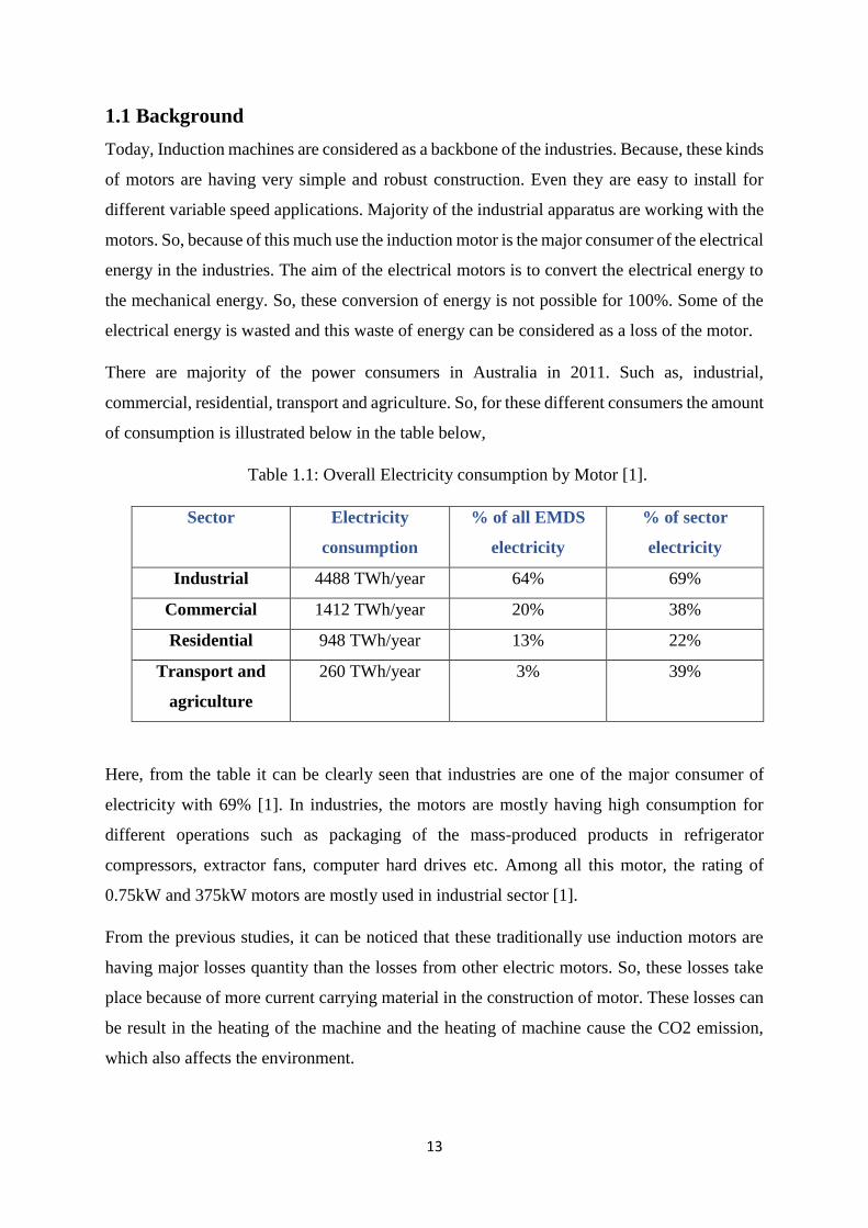
There are majority of the power consumers in Australia in 2011. Such as, industrial,
commercial, residential, transport and agriculture. So, for these different consumers the amount
of consumption is illustrated below in the table below,
Table 1.1: Overall Electricity consumption by Motor [1].
Sector Electricity
consumption
% of all EMDS
electricity
% of sector
electricity
Industrial 4488 TWh/year 64% 69%
Commercial 1412 TWh/year 20% 38%
Residential 948 TWh/year 13% 22%
Transport and
agriculture
260 TWh/year 3% 39%
Here, from the table it can be clearly seen that industries are one of the major consumer of
electricity with 69% [1]. In industries, the motors are mostly having high consumption for
different operations such as packaging of the mass-produced products in refrigerator
compressors, extractor fans, computer hard drives etc. Among all this motor, the rating of
0.75kW and 375kW motors are mostly used in industrial sector [1].
From the previous studies, it can be noticed that these traditionally use induction motors are
having major losses quantity than the losses from other electric motors. So, these losses take
place because of more current carrying material in the construction of motor. These losses can
be result in the heating of the machine and the heating of machine cause the CO2 emission,
which also affects the environment.

14
To overcome this kind of losses in the motors, today there are so many researches going on.
Because it is the biggest threat on the world. International Electrotechnical commission has
introduced the international standards in the production of the electric motor. They stated some
of the efficiency levels for different rating of the motors. Also, the Australian government has
started initiative named MEPS from the year 2011. Table 1.2, shows the minimum efficiency
standards for Australia.
Table 1.2 Minimum three phase motor efficiency standards in Australia [2].
Rated Output
kW Minimum Efficiency %
2 pole 4 pole 6 pole 8 pole
0.73 78.8 80.5 76.0 71.8
0.75 78.8 80.5 76.0 71.8
1.1 80.6 82.2 78.3 74.7
1.5 82.6 83.5 79.9 76.8
2.2 84.1 84.9 81.9 79.4
3 85.3 86.0 83.5 81.3
4 86.3 87.0 84.7 82.8
5.5 87.2 87.9 86.1 84.5
7.5 88.3 88.9 87.3 86.0
11 89.5 89.9 88.7 87.7
15 90.8 90.8 89.6 88.9
Also, the European union has placed new standards of efficiency to produce the electric motor.
In those standards, they divided in four various parts such as IE1, IE2, IE3 and IE4. Where,
IE1 is the standard efficiency, IE4 stands for super premium efficiency. Also, the researchers
are continuously trying to achieve the ultra-premium efficiency IE5 [2]. So, here the aim is to
design the axial flux double sided rotor line-start PM motor.

15
1.2 Problem statement
Traditionally, the induction motors are majorly used in the industries and also for the house
hold applications. Due to lower efficiency of induction motor, motor takes more input power.
The more generation of power leads to the CO2 emission. It is the serious environmental
problem.
Basically, the reason for the losses in the machines are the copper winding and the friction
during the rotation as well as the core of the motor. So, the copper quantity can be reduced by
designing the new motor with the inductor bars.
Also, the radial flux machines are bulkier and occupy more space during its application. So,
the idea arises in mind to design the motor working with axial flux phenomenon. And there are
plenty of advantages of developing the axial flux motor.
There are many developers in the market named ABB, SIEMENS, GE, SEW in the production
of electrical machine. But, for this new configuration of the design another idea was attached
of self-starting of the motor. So, to overcome these problems the whole modern design of the
axial flux line start motor with the PM is developed.
The Axial flux motor is having large cogging torque compared to traditionally used motors.
So, these types of motors can be used in the different applications such as ship propulsion,
elevators. Also, because of high efficiency and high torque, it can be also used in the application
of the transport and military. These types of the motors reduce the losses and the overall
efficiency of these machines is high. Which is ultimately helps to reduce the emission of CO2.
For the optimization of the best design, there are basically 3 design of line-start axial flux
permanent magnet synchronous motor were finalized with different design of inductor bars
with aluminium and copper material of inductor bar.
16
1.3 Objectives
• To study the performance of 8 pole 50Hz 1.1kW, average 335V induction motor as a
benchmark model.
• To design a double-sided rotor line-start axial flux permanent magnet synchronous
motor of 1.5kW 8 pole 50Hz.
• To simulate LSAFPMSM with three different type of inductor bar with aluminium
and copper material.
• To compare the performance of LSAFPMSM and induction motor under different
load condition.
1.4 Methodology
The Finite Element Analysis (FEA) is used for simulation of motor. The ANSYS Maxwell 3D
2015 version software is used for simulation of motor. Mostly, this software is industry
standard simulation program to performed Magnetostatic, open circuit test and transient
analysis for better accurate result of motor. First, the induction motor is designed in ANSYS
Maxwell 3D software and the simulation is done with the help of finite element analysis
method. Three-phase 8 pole 50Hz, 1.3kW induction motor is designed. This motor is taken as
a benchmark model. And the motor is simulated for magnetostatic and transient analysis. The
line-start axial flux permanent magnet synchronous motor is designed in same software. The
stator design is same as induction motor but the rotor design is different for both model. The
three types of inductor bar are designed for LSAFPMSM. The simulation of these three types
of LSAFPMSM is carried out using this software. The magnetostatic and transient analysis of
LSAFPMSM is obtained. Finally, the FEA application is used with ANSYS Maxwell 3D in
this research.
1.5 Limitations
All the motors are designed in Maxwell 3D using FEA. The 3D design takes too much time for
simulation. The 3D design is also very expensive with respect to processor of computer. So,
2D design model is often used in replace of 3D design because 2D model take less
computational time. But, the axial flux machine cannot be converted to 2D design. So, the
results of 2D model is not accurate as 3D model simulation.

17
1.6 Scope
The scope of the research is to design and analysis of 1.5kW line-start axial flux permanent
magnet synchronous motor with double sided rotor slotted stator and to design 1.3kW induction
motor with slotted stator configuration. the simulation for both motor will be performed under
different loading condition. The three-type inductor bar is designed for LSAFPMSM. The
magnetostatic and transient analysis of all motor is performed using Maxwell 3D FEA method.
The Maxwell 3D is used to design all motor for better results of motors.
1.7 Outline
Chapter 1: Introduction
Chapter 1 gives an overview and background of project. The problem statement describes the
problem with other motor. The methodology, limitation and scope of the project are also
included in this chapter.
Chapter 2: Literature Review
Chapter 2 consists the previous research information which guide the direction of research in
different area of this thesis. The literature review also gives the detail of previous research
paper which is contributing and related to this project. Mostly, the research paper is presented
on the LSAFPMSM for design and analysis process.
Chapter 3: Design Aspects and Justification
This chapter provides the design aspects and justification which are used for designing of
machine. The whole machine geometry and design properties of stator, rotor, inductor bar and
magnet of motor is specified in this chapter. The final 3D design of all model is illustrated in
this chapter.
Chapter 4: Method of Simulation
The chapter 4 gives the detail information about the simulation method and about the software
which is used for simulation in 3D. The magnetic analysis and open circuit test is included in
this chapter. This chapter ends with the simulation results.
Chapter 5: Results and Discussion
Chapter 5 represents the results of transient analysis. The motor is tested to evaluate for its
performance parameter at different loading condition. The results are obtained for

18
LSAFPMSM and Induction motor. The results of both motor are compared to obtained the
better performance of motor.
Chapter 6: Conclusion and Future work
Chapter 6 provides the brief conclusion from the results of all motors. This chapter ends with
discussion of key finding and future direction of this project from the obtained result of motor.

19
Chapter 2: Literature Review

20
2.1 Introduction
In last 10 years, there are many research executed in the field of electrical engineering. The
different type of motors is developed in these researches. There are many types of motors are
designed for different types of applications. All the new designs have its advantages and
disadvantages. There is not specific method for design and analysis purpose, all the researches
are carried out with different methods using different software. This literature review starts
with previous paper discussing general design and analysis of line start axial flux permanent
magnet synchronous motor and induction motor. In the second part of review research gap is
discussed.
2.2 Induction Motor
The different methods of electrical motor design and analysis is illustrated in many research
paper. But, there are few paper which discussed about design of the motor. Livadaru L,Simion
A, Munteanu A, Sandru M [3] have published a paper for designing and simulation of induction
motor. In this study, a high-power induction motor rating of 630kW is designed. The deep bar
double squirrel cage rotor is used to increase torque and to decrease starting current. While the
stator has double layer winding. The finite element method is used for steady-state operation
and transient analysis of the motor. It concludes, due to special construction of rotor, it required
a high starting torque and low starting current.
Contreras S, Cortes C and Guzman M [4] present their study with modelling of squirrel cage
induction motors of rating 3.7kW two pole. This motor is modelled in two ways such as finite
element method and analytic equivalent circuit. The Bio-inspired multi-objective optimization
algorithm is used to improve the design of motor and motor is validate through FEM. It is
concluded that an equivalent circuit of motor can be used with given algorithm technic and
discussed different parameters of motor.
Ruthes J, Nau S and Nied A [5] conducted a study on analysis of induction motor under non-
sinusoidal supply voltage. The three methods Analytical Models (AM), Finite element method
(FEM) and Magnetic Equivalent Circuit (MEC) are used for modelling and design of induction
motor. But AM has disadvantages of accuracy so this method is used in analyzing in small
changes while FEM method has provided stator rotor slot, distribution of stator winding but
this method takes more computation time. The MEC method is very precious and less
complexity of model. This paper concluded that the FEM and MCA methods are better with
results as compared to AM and MEC takes less simulation time and more suitable.

21
Srinivasan J, Selvaraj K, Chitrarasu J and Resmi R [6] compared the full pitch and short pitch
winding configuration of three phase squirrel cage induction motor rated 1.1kW, 500 rpm and
12 poles. Using the finite element method, the harmonic of winding current of motor is
compared for both configuration. The stator has double layer winding with two coils placed in
a single slot and simple rotor construction is used. In the results, the graph of air gap flux
density of full and short pitch and magnetic flux density of motor are obtained. From the results,
it concluded that full pitch winding has more harmonics as compared to short pitch winding.
Pyrhonen J, Jokinen T and Hrabovcova V [7] published a book name “Design of Rotating
Electrical Machines”. They provide a theoretical background for designing of electrical
machine with equations which are used for designing. In the detail, they discussed on method
of design, winding of machines, design of magnetic circuit, calculation of airgap, flux line and
obtained the graph of speed and efficiency at different load conditions.
2.3 Axial Flux and Radial Flux Machine
Cavagnino A, Lazzari M and Profumo F [8] have compared axial flux structure and
conventional radial flux structure machines. The two motor designs are selected and compared
both in terms of electromagnetic torque with different dimensions and pole numbers. During
the test the overall volume of motor, losses and flux density are taken as constant. It concluded
that the axial flux machine is more suitable when number pole is high and axial length is short.
Patterson D, Colton J, Mularcik B and Kennedy B [9] have studied on comparison of radial
and axial structures in electrical machine. The single sided geometry is used for axial flux and
for radial flux inside rotor geometry is used. This paper concludes that axial flux has large
torque arm with same radius and it required less material as compared to radial flux machines.
So, the cost of radial flux machine is high.
Upadhyay P.R. and Rajagopal K.R. [10] have compared axial and radial field permanent
magnet brushless DC motor rating of 350 rpm and 70W. Two methods, Computer aided design
(CAD) and finite element method are used for comparison. The different parameters of motor
are calculated in CAD and EFM is used for validation in 2-D and 3-D. From the obtain results
it concludes that axial field motor is preferable than radial field. The axial field motor has high
efficiency.
Sitapati K and Krishnan R [11] discussed on comparison of radial and axial field permanent
magnet brushless machines. The four-novel design of machine such as single gap and dual gap

22
slotted axial field machine and single gap and dual gap slot less axial field machine are
compared with one radial filed machine. The five-different power rating and two rated speed
is used for designing. The comparison consists in terms of losses, power, torque, magnet size
and inertia of machine. It concludes that, the axial filed machine is superior in terms of smaller
volume of material and high-power density.
Pravianiem A, Niemela M and Pyrhonen J [12] has compared low speed axial and radial flux
surface mounted machines. The comparison is based on the efficiency and volume of the
machine. This research concludes that efficiency of axial flux machine is low with same
electrical loading and air fap flux density but the efficiency can be improved by increasing
volume. The efficiency also improved by using more poles.
2.4 Line-start Axial Flux permanent magnet synchronous motor
Mahmoudi A, Kahourzade S, Uddin M, Rahim N and Hew W.P. [13] present a novel design
of line-start axial flux permanent magnet synchronous motor using finite element analysis
method. The 4-pole slot less double-sided rotor configuration is used for high torque density
and stable rotation of motor so the motor can operate at synchronous speed and the prototyping
of the motor is presented. The steady state and transient performance is analyzed with FEM.
From the results, the speed of the motor synchronizes at rated speed and sufficient starting
torque. This type of motor is suitable for high-speed application.
Ugale R.T., Bhanuji A and Chaudhari B. N. [14] conducted a study on novel design of rotor.
The permanent magnet which is place in rotor so the design of the rotor is very complex. So,
this paper presents a new two-part rotor design which gives synchronous speed and
performance of motor. The two-part rotor design gives a wide choice of machine parameters
and axial length does not depend on it. The result shows that torque of two-part rotor is 1.3
times higher than spoke rotor. So, motor run with high starting torque in starting and torque is
constant at steady state performance.
Tsuboi K, Takegami T, Hirotsuka I and Nakamura M [15] have discussed about the
performance and calculation of three phase LSPMM using general analytical method. Using
this method, the current and torque is calculated. Moreover, the vibratory torque can be
calculated in less time. In the conclusion, the characteristics of three phase LSPMM can be
calculated in very less time by using this method. This method also can be used for reducing
vibration and noise of the motor. The combination of this method and FEM method gives better
design and magnetic flux of the motor.

23
Feng X, Bao Y, Liu L, Huang L and Zhang Y have [16] compared line start-up permanent
magnet synchronous motor (LSPMSM) to the premium efficient induction motor (PEIM) in
terms of design and starting performance of these motor using finite element analysis (FEA).
Two types of rotor design, semi-closes slot and fully closed slot rotor are designed by
combination of squirrel cage and permanent magnet poles. FEA is used to analyses starting
torque, cogging torque, mechanical stress, no load voltage etc. this study concludes that
LSPMSM has higher efficiency, power factor and less material used as compared to PEIM.
Fei W, Luk P.C.K, Ma J, Shen J and Yang G [17] have present an amended high performance
LSPMSM from small three phase induction motor. For the modification, the stator and winding
pattern are same but the size of copper wire and coil turn are changed to get unity power factor.
The four-pole rotor with permanent magnet is used for high energy at high temperature. 36
pyriform slots with flat bottom rotor is used for high efficiency LSPMSM. The analyses of this
motor are done with FEA using ANSOFT MAXWELL 2-D. It concludes that new developed
LSPMSM has increase efficiency and power factor with minimum changes at minimum extra
cost.
Kul S, Bilgin O and Mutluer M [18] have discussed about the application of finite element
method (FEM) to determine the performance of LSPMSM. This study focus on 1.1kW, 4-pole
LSPMSM. This motor is designed in ANSYS MAXWELL Rmxprt software and then the motor
can be converted into 2-D/3-D finite element modelling. The rotor consists permanent magnet
and damper winding while stator has armature winding. The transient analysis is performed to
get graph of efficiency, breaking torque and speed. Form the results it can be say that,
efficiency, breaking torque and power factor can be depend on the magnet dimension and
breaking torque is proportional to magnet dimension.
2.6 Gap Statement
Among all the mentioned literature review for the specified permanent magnet motor has been
carried out. Most of the paper focus on the three-phase permanent magnet synchronous motor
with different analyses method. But there is less research was done in three-phase line start
permanent magnet synchronous motor for constant speed application with higher efficiency
and better power factor. The novel design of the rotor can be done on the LSPMSM. The
performance of this motor can be achieved by transient and steady state analysis using finite
element method in ANSYS MAXWELL 3-D.

24
2.7 Contribution
The aim of this project is to design and analyses of three-phase double sided rotor axial-flux
permanent magnet synchronous motor to get better efficiency and power factor than Induction
motor. This analysis is performed for the direct drive double sided rotor with permanent magnet
design motor for constant speed. The analysis is performed to get results in different loading
condition of the motor.
25
Chapter 3: Design Aspects and
Justification

26
3.1 Induction motor as a benchmark model
In this project, the induction motor of rating 1.1kW, 8-pole, 50Hz is taken as a benchmark
model. The exploded view of the induction motor is shown in figure 3.1. Mostly, the induction
motor consists rotor, stator and inductor bars. Double sided rotor configuration used for this
motor. The inductor bars built in the rotor which is made from cast aluminium material. The
slotted stator has 24 slots and windings are applied to three phase voltage supply. The motor is
run on the principal of electromagnetic induction which obtained by rotor from the stator
windings. Now a day, three-phase induction motor is widely used for industrial application and
single-phase induction motor used for small household application. The induction motor
always run less than synchronous speed due to lagging flux current in rotor.
Figure.3.1: Exploded view of Induction motor
The different views of the induction motor are shown in figure 3.2. The synchronous speed is
the speed of rotating magnetic field which is defined as given formula.
𝑁𝑠 = 120 ×𝑓
𝑃 (𝑅𝑃𝑀)
Where, P is total number of poles and f is supply frequency.

27
Figure 3.2: Different views of induction motor in 3-D
The difference between synchronous speed and actual speed is called percentage ration of slip
s. Slip of the motor can be calculated by formula:
% 𝑠𝑙𝑖𝑝 𝑠 =𝑁𝑠 − 𝑁
𝑁𝑠× 100
Where, NS is synchronous speed and N is actual speed of motor.
The torque of the induction motor is proportional to the flux per pole, rotor current and power
factor which can be formulated as,
𝑇 ∝ 𝜙 𝐼2 𝑐𝑜𝑠𝜃2
Where, T is torque. I2 is rotor current, cosθ2 is power factor of rotor and ϕ is flux which
produced by induced emf.
The formula for maximum torque of three phase induction motor derived as,
Where, s is slip of motor. E2 is rotor emf, R2 is rotor resistance and X2 is rotor reactance. Ns is
synchronous speed of the motor.

28
3.1.1 Specification of induction motor
The dimension and general data of the induction motor is given in table. The rating of motor is
1.1kW, 8-pole at rated speed of 727 rpm.
The slotted stator with 24 slots is used for motor design. The material M19_29G steel is used
for stator. The inner and outer radius of stator is 90mm and 150mm respectively. The same
steel material is used for rotor. The double-sided rotor geometry is used in this motor design.
The inductor bar is made of aluminium material which are fit with rotor.
Table 3.1: Specification of Induction motor
General data of machine
Given output power (kW) 1.1
Number of poles 8
Given speed (rpm) 727
Frequency (Hz) 50
Average Voltage Rating (V)
335
Stator data
Inner radius (mm) 90
Outer radius (mm) 150
Thickness (mm) 20
Rotor data
Inner radius (mm) 90
Outer radius (mm) 150
Thickness (mm) 2.5
3.1.2 Stator
The slotted stator which is made from laminated iron is used in this design. The 24 stator slots
are filled with same number of windings as shown in figure 3.4. The winding colour Blue, Red
and Green indicates Phase A, Phase B and Phase C respectively.

29
(a) Slotted stator (b) Slotted stator with windings
Fig.3.3: Design of slotted stator
3.1.3 Rotor
The main part of the project is having a double-sided rotor with inductor bars as shown in
figure1. The same material M19_24G steel as stator is used in rotor. The inductor bar is fitted
in the rotor which is made of aluminium material as shown in figure 3.5.
Fig.3.4: Rotor with Inductor bars

30
3.2 Design of Axial-flux machine
The research conducted on the axial-flux permanent magnet synchronous motor (AFPMSM)
with double sided rotor slotted stator configuration using toroidal windings. This type of
machine is also called as torus configuration. The exploded view of the machine is shown in
figure 3.6. The double-sided rotor which covered stator and other parts of the motor. The
magnets are fitted inside the rotor. The different 3-D views of AFPMSM displayed in figure
3.7.
Fig.3.5: Exploded view of Axial-flux synchronous motor
Fig.3.6: Diffrent 3-D views of AFPMSM

31
Here, the magnets are design as arc shape with colour red for north pole and blue for south
pole. The same colour is used for phase as induction motor which is wound around the stator.
3.3 Machine arrangement of Axial-flux machine
There are mainly four different types of arrangement has done as per different application, size
of motor, cost and many other specified parameters of motor.
Fig.3.7: Single stator, single rotor Fig.3.8: Single stator, double rotor (SSDR)
Fig 3.8 and 3.9 illustrate two machine arrangements of the AFPMSM one is single stator, single
rotor (SSSR) and other is single stator, double rotor (SSDR). The other two types are double
stator, single rotor (DSSR) and multistage of stator and rotor. This project mainly focuses on
the single stator, double rotor which is also called as TORUS type. This configuration is used
for both induction motor and AFPMSM.
3.4 Stator configuration for LSAFPMSM
The stator configuration of induction motor and LSAFPMSM is same with dimension. It has
slotted stator with 24 slots. The stator diameter can be change according to the application of
motor. In this project, the stator diameter is same as rotor diameter as shown in figure 3.10.

32
Fig.3.9: Stator of LSAFPMSM with windings
Fig.3.10: Stator dimension
3.4.1 Windings of Stator
The copper material is used for winding of stator. The I2R losses is consider for the windings.
The blue, red and green colour are set for three phases. This design has 24 copper winding
around the stator. The material properties of copper are described in table 3.2. Three-phase
winding diagram of stator is shown in figure 3.11.
33
Table 3.2: Properties of copper material for rotor
Name Type Value Units
Relative
Permeability
Simple 0.999991 𝐵/𝐻
Bulk Conductivity Simple 580000000 Ω−1⁄𝑚
Magnetic Coercivity Vector -
Magnitude Vector Mag 0 𝐴/𝑚 Core Loss Model None 𝑊/𝑚3
Mass Density Simple 8933 𝑘𝑔/𝑚3 Composition Solid -
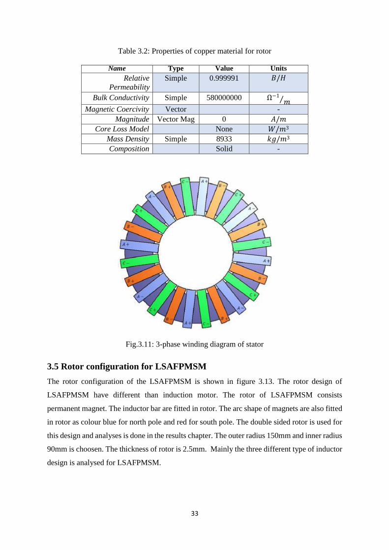
Fig.3.11: 3-phase winding diagram of stator
3.5 Rotor configuration for LSAFPMSM
The rotor configuration of the LSAFPMSM is shown in figure 3.13. The rotor design of
LSAFPMSM have different than induction motor. The rotor of LSAFPMSM consists
permanent magnet. The inductor bar are fitted in rotor. The arc shape of magnets are also fitted
in rotor as colour blue for north pole and red for south pole. The double sided rotor is used for
this design and analyses is done in the results chapter. The outer radius 150mm and inner radius
90mm is choosen. The thickness of rotor is 2.5mm. Mainly the three different type of inductor
design is analysed for LSAFPMSM.

34
Fig.3.12: Rotor of LSAFPMSM with magnets
Fig.3.13: Rotor dimension
3.5.1 Design of Inductor bar
The inductor bars are fitted in the rotor as shown in figure 3.13. In this project three types of
inductor bar design are analysed. The motor is tested with these three-inductor design with
aluminium and copper material. The dimension of three inductor is different. The line-start
axial flux permanent magnet synchronous motor is tested with three different types of inductor
bar. The design and dimension of these three-inductor bar is different.
35
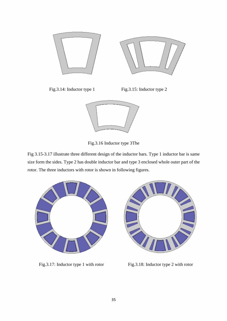
Fig.3.14: Inductor type 1 Fig.3.15: Inductor type 2
Fig.3.16 Inductor type 3The
Fig 3.15-3.17 illustrate three different design of the inductor bars. Type 1 inductor bar is same
size form the sides. Type 2 has double inductor bar and type 3 enclosed whole outer part of the
rotor. The three inductors with rotor is shown in following figures.
Fig.3.17: Inductor type 1 with rotor Fig.3.18: Inductor type 2 with rotor

36
Fig.3.19: Inductor type 3 with rotor
Normally, the inductor bars are made from aluminium material. So, the eddy current losses are
major concern for the motor which is the reason of low efficiency and larger losses of motor.
In this project, copper material is also used for inductor bar. The properties of both material are
shown in following tables.
Table 3.3: Properties of aluminium material for inductor
Name Type Value Units
Relative
Permeability
Simple 1.000021 𝐵/𝐻
Bulk Conductivity Simple 38000000 Ω−1⁄𝑚
Magnetic Coercivity Vector -
Magnitude Vector Mag 0 𝐴/𝑚
Core Loss Model None 𝑊/𝑚3
Mass Density Simple 2689 𝑘𝑔/𝑚3 Composition Solid -
Table 3.4: Properties of copper material for inductor
Name Type Value Units
Relative
Permeability
Simple 0.999991 𝐵/𝐻
Bulk Conductivity Simple 58000000 Ω−1⁄𝑚
Magnetic Coercivity Vector -
Magnitude Vector Mag 0 𝐴/𝑚
Core Loss Model None 𝑊/𝑚3 Mass Density Simple 8933 𝑘𝑔/𝑚3
Composition Solid -

37
3.5.2 Shape of magnets
The shape of the magnet is arc type used for AFPMSM. The N36Z_20 material is used for
magnets with relative permeability of 1.03. This type of magnet is easily available. Thickness
of magnet is 10mmwith axial length of 43.06mm. The dimension of the magnet is changed for
all three types of inductor.
Fig.3.20: Magnet shape
Table 3.5: Properties of N36Z_20 material for magnets
Name Type Value Units
Relative
Permeability
Simple 1.03 𝐵/𝐻
Bulk Conductivity Simple 620000 Ω−1⁄𝑚
Magnetic Coercivity Vector -
Magnitude Vector Mag -920000 𝐴/𝑚
𝑋 − 𝐶𝑜𝑚𝑝𝑜𝑛𝑒𝑛𝑡 Unit Vector 1 -
𝑌 − 𝐶𝑜𝑚𝑝𝑜𝑛𝑒𝑛𝑡 Unit Vector 0 -
𝑍 − 𝐶𝑜𝑚𝑝𝑜𝑛𝑒𝑛𝑡 Unit Vector 0 -
Core Loss Model None 𝑊/𝑚3
Mass Density Simple 0 𝑘𝑔/𝑚3
Composition Solid -

38
3.6 Electrical Steel
The electrical steel material M19_29G is assigned to the stator and rotor cores. It has 7650
kg/m3 mass density with stacking factor of 0.92. Here, letter M indicates magnetic material.
The magnetic properties of steel are same in all direction. The 19 number indicate grade of core
loss of non-oriented steel. The 29G indicates thickness of laminated steel. The properties of
electrical steel M19_29G are listed in table 3.6 and the B-H curve is shown in figure 3.21.
Table 3.6: Properties of M19_29G material (Electrical steel)
Name Type
Value
Units
Relative
Permeability
Nonlinear 𝐵/𝐻
Bulk Conductivity Simple 1960000 Ω−1⁄𝑚
Magnetic Coercivity Vector -
Magnitude Vector Mag 0 𝐴/𝑚
𝑋 − 𝐶𝑜𝑚𝑝𝑜𝑛𝑒𝑛𝑡 Unit Vector 1 -
𝑌 − 𝐶𝑜𝑚𝑝𝑜𝑛𝑒𝑛𝑡 Unit Vector 0 -
𝑍 − 𝐶𝑜𝑚𝑝𝑜𝑛𝑒𝑛𝑡 Unit Vector 0 -
Core Loss Model Electrical Steel 𝑊/𝑚3 𝐾𝑙ℎ Simple 164.2 - 𝐾𝑙𝑐 Simple 0.409 - 𝐾𝑙𝑒 Simple 0 - 𝐾𝑑𝑐 Simple 0 -
Mass Density Simple 7650 𝑘𝑔/𝑚3 Composition Solid -
Fig.3.21: B-H curve for M19_29G electrical steel

39
Table.3.7: Summary of dimensions of LSAFPMSM
All dimension
(mm)
Type 1 Inductor
model
Type 2 inductor
model
Type 3 inductor
model
Rotor outer radius 150 150 150
Rotor inner radius 90 90 90
Rotor thickness 2.5 2.5 2.5
Stator outer radius 150 150 150
Stator inner radius 90 90 90
Stator thickness 20 20 20
Inductor axial width 60 60 60
Inductor length 70.6 117.8 114.5
Inductor thickness 10 10 10
Magnet axial width 43.06 43.06 43.06
Magnet length 42.5 42.5 68.5
Magnet thickness 10 10 10
Finally, all the above design of Line-start axial flux permanent magnet synchronous motor is
finalised for the simulation and testing. The simulation of three models of LSAFPMSM are
described in next chapter with different analysing process.

40
Chapter 4: Method of Simulation
41
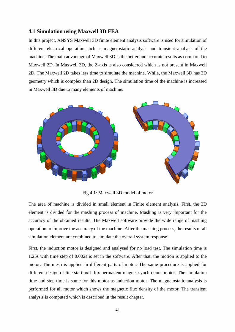
4.1 Simulation using Maxwell 3D FEA
In this project, ANSYS Maxwell 3D finite element analysis software is used for simulation of
different electrical operation such as magnetostatic analysis and transient analysis of the
machine. The main advantage of Maxwell 3D is the better and accurate results as compared to
Maxwell 2D. In Maxwell 3D, the Z-axis is also considered which is not present in Maxwell
2D. The Maxwell 2D takes less time to simulate the machine. While, the Maxwell 3D has 3D
geometry which is complex than 2D design. The simulation time of the machine is increased
in Maxwell 3D due to many elements of machine.
Fig.4.1: Maxwell 3D model of motor
The area of machine is divided in small element in Finite element analysis. First, the 3D
element is divided for the mashing process of machine. Mashing is very important for the
accuracy of the obtained results. The Maxwell software provide the wide range of mashing
operation to improve the accuracy of the machine. After the mashing process, the results of all
simulation element are combined to simulate the overall system response.
First, the induction motor is designed and analysed for no load test. The simulation time is
1.25s with time step of 0.002s is set in the software. After that, the motion is applied to the
motor. The mesh is applied in different parts of motor. The same procedure is applied for
different design of line start axil flux permanent magnet synchronous motor. The simulation
time and step time is same for this motor as induction motor. The magnetostatic analysis is
performed for all motor which shows the magnetic flux density of the motor. The transient
analysis is computed which is described in the result chapter.
42
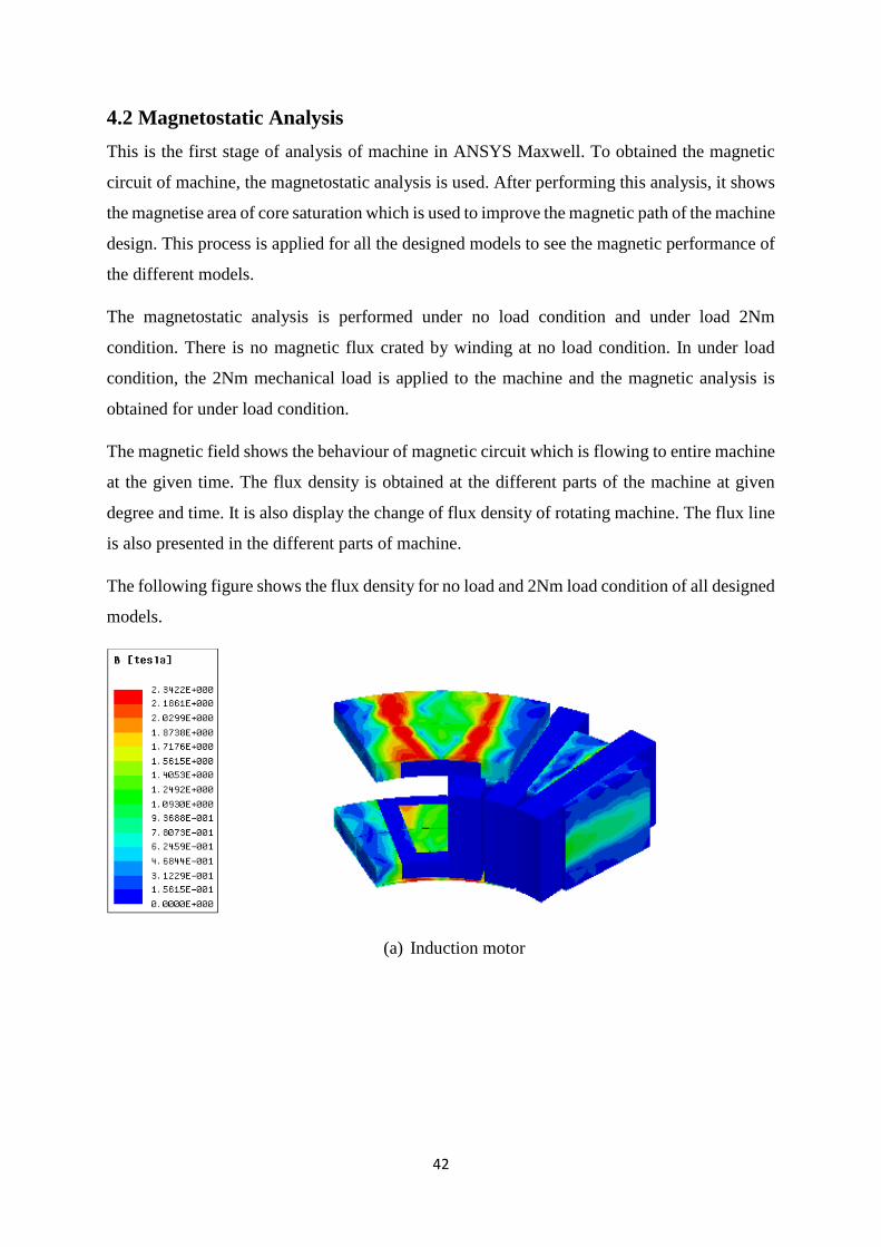
4.2 Magnetostatic Analysis
This is the first stage of analysis of machine in ANSYS Maxwell. To obtained the magnetic
circuit of machine, the magnetostatic analysis is used. After performing this analysis, it shows
the magnetise area of core saturation which is used to improve the magnetic path of the machine
design. This process is applied for all the designed models to see the magnetic performance of
the different models.
The magnetostatic analysis is performed under no load condition and under load 2Nm
condition. There is no magnetic flux crated by winding at no load condition. In under load
condition, the 2Nm mechanical load is applied to the machine and the magnetic analysis is
obtained for under load condition.
The magnetic field shows the behaviour of magnetic circuit which is flowing to entire machine
at the given time. The flux density is obtained at the different parts of the machine at given
degree and time. It is also display the change of flux density of rotating machine. The flux line
is also presented in the different parts of machine.
The following figure shows the flux density for no load and 2Nm load condition of all designed
models.
(a) Induction motor

43
(b) LSAFPMSM tyep 1 inductor (left) Aluminium (right) copper material
(c) LSAFPMSM tyep 2 inductor (left) Aluminium (right) copper material
(d) LSAFPMSM tyep 3 inductor (left) Aluminium (right) copper material
Fig. 4.2: Magnetic flux density of motors at no load

44
(a) Induction motor
(b) LSAFPMSM tyep 1 inductor (left) Aluminium (right) copper material
(c) LSAFPMSM tyep 2 inductor (left) Aluminium (right) copper material
(d) LSAFPMSM tyep 3 inductor (left) Aluminium (right) copper material
Fig.4.3: Flux density of motors at 2Nm load

45
The magnetic flux density of all models at no load condition is shown in figure 4.2. The
amgnetic flux denstiy is high in the core part of staor and rotor of the motor. The flux density
is measured in tesla with the range between 0 tesla to 2.34 tesla. Here, the orange and green
area indictes the high flux density of rotor and stator while the blue area indicated low flux
density of stator and rotor. It can be noticed that, the LSAFPMSM models have more magtetic
flux denstiy than the induction motor. Figure 4.3 illustate the magnetic flux denstiy at 2Nm
under load condition. LSAFPMSM have better flux density at given load condition. The range
of flux density for 2Nm load is 0 to 2 tesla. The rotor has high secturation for LSAFPMSM
models at 2Nm load.
Now, the next step is to plot the magnetic flux vector for all model. Using the flux vector, the
intensity of flux can be identified in the all parts of the motor. The flux vectro is obtained for
no load and for 2Nm load. The following figure 4.4 represent the magnetic flux vector at no
load and 2Nm load condition.
(a) Induction motor
(b) LSAFPMSM tyep 1 inductor (left) Aluminium (right) copper material

46
(c) LSAFPMSM tyep 2 inductor (left) Aluminium (right) copper material
(d) LSAFPMSM tyep 3 inductor (left) Aluminium (right) copper material
Fig.4.4: Magnetic flux vector of motors at no load
The magnetic flux vector for 2Nm load is represented in following figure 4.5.
(a) Induction motor

47
(b) LSAFPMSM tyep 1 inductor (left) Aluminium (right) copper material
(c) LSAFPMSM tyep 2 inductor (left) Aluminium (right) copper material
(d) LSAFPMSM tyep 3 inductor (left) Aluminium (right) copper material
Fig.4.5: Magnetic flux vector of motors at 2Nm load
The figure 4.5 shows the magnetic flux vector at 2Nm load. The magnetic flux vector represent
the direction and a magnitude of machine. The magnetic flux vector is used to predict the effect
of a magnet on magnetic filed. The orange and green colour shows the high magnetic lux vector
on the different parts of motor. The LSAFPMSM have better magnitude and direction of vector
as compared to induction motor.
48
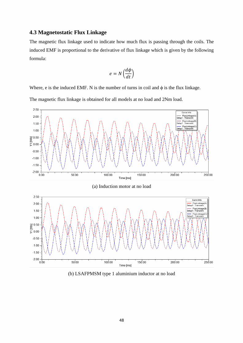
4.3 Magnetostatic Flux Linkage
The magnetic flux linkage used to indicate how much flux is passing through the coils. The
induced EMF is proportional to the derivative of flux linkage which is given by the following
formula:
𝑒 = 𝑁 (𝑑𝜙
𝑑𝑡)
Where, e is the induced EMF. N is the number of turns in coil and ϕ is the flux linkage.
The magnetic flux linkage is obtained for all models at no load and 2Nm load.
(a) Induction motor at no load
(b) LSAFPMSM type 1 aluminium inductor at no load

49
(c) LSAFPMSM type 1 copper inductor at no load
(d) LSAFPMSM type 2 aluminium inductor at no load
(e) LSAFPMSM type 2 copper inductor at no load

50
(f) LSAFPMSM type 3 aluminium inductor at no load
(g) LSAFPMSM type 3 copper inductor at no load
Fig.4.6: Magnetic flux linkage at No load
The above figure 4.6 shows the magnetic flux linkage at no load condition. Three-phase flux
linkage is represent using the different colour. The magnetic flux linkage of all motor is
sinusoidal. Due to the saturation in the core, the waveform of linkage is fluctuating in the
starting condition of machine but after that the waveform get sinusoidal as shown in the results.
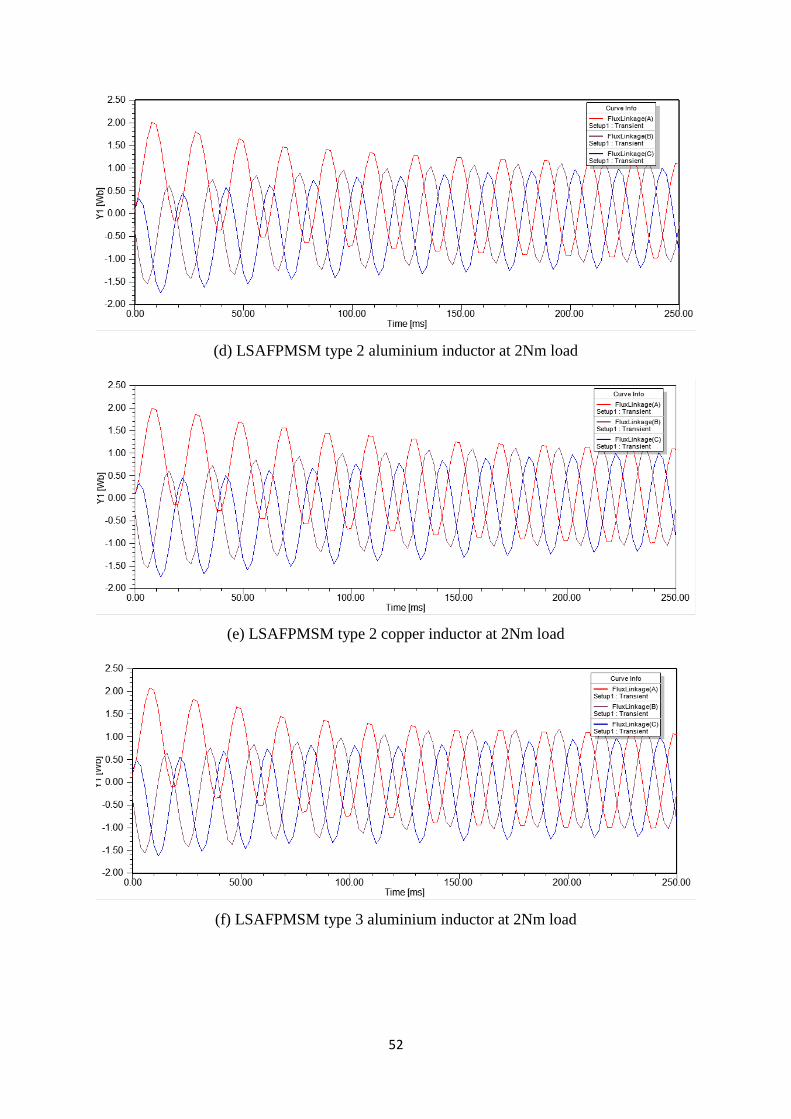
Now, the magnetic flux linkage is tested for the 2Nm load for all machines which is illustrated
in the flowing figure.
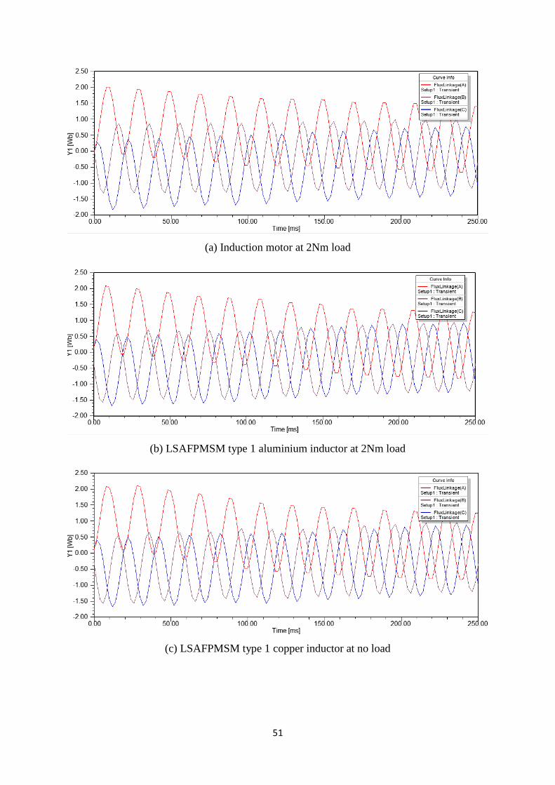
51
(a) Induction motor at 2Nm load
(b) LSAFPMSM type 1 aluminium inductor at 2Nm load
(c) LSAFPMSM type 1 copper inductor at no load
52
(d) LSAFPMSM type 2 aluminium inductor at 2Nm load
(e) LSAFPMSM type 2 copper inductor at 2Nm load
(f) LSAFPMSM type 3 aluminium inductor at 2Nm load

53
(g) LSAFPMSM type 3 copper inductor at 2Nm load
Fig.4.7: Magnetic flux linkage at 2Nm load
From the figure 4.7, it can be seen that the magnetic flux linkage at 2Nm load is identical to
the no load flux linkage. But, there is small difference in the shape and amplitude of the
waveform. During the starting performance of motor there is some fluctuation in the waveform
but after that it should be sinusoidal waveform for all machine. One of the reason to increase
in core loss is increasing the alternating flux frequency. The adjustment in magnetic flux
linkage has directly affect the induced EMF. The expanded frequency and diminished
magnitude of the flux linkage is directly relative to expansion in frequency and decrease in the
magnitude of EMF.
4.4 Summary of Magnetostatic Analysis
In this section, the magnetostatic analysis is implemented for the all designed machines. The
magnetic flux density plot for all machine is achieved. From the flux density plot, the
perfomance of magnetic circuit is carried out in this analysis. The flux denstiy shows the
magnetic behaviour of the different parts of machine. The magnetic vector shows the direction
and filed of the flux in the machine. The magnetic flux linkage is carried out for all
machine.which shows the relation to the EMF of the machines. The flux linkage of all machine
has almost same but there is minor difference in the magnitude and shape of waveform. There
is also some phase diffrance of waveform at no load and 2Nm load conditions. But, overall the
flux linkage of all machine is sinusoidal. Finally, the magnetostatic analysis is perfomed for
magnetic perfomance of machine using FEA.

54
4.5 No load test analysis
In the open circuit test, the machine is operated on no electrical load. Mostly, the open circuit
test is used to measured induced voltage at rated speed.
4.5.1 Induced voltage measurement
The induced voltage can be measured at rated speed under open circuit test of machine. The
induced voltage is obtained by permanent magnets in LSAFPMSM which is measured at rated
speed of 750 rpm. There is no excitation given to the stator winding. The induced voltage is
measured for 1.25s with time step of 0.002s.
(a) LSAFPMSM type 1 aluminium inductor
(b) LSAFPMSM type 1 copper inductor

55
(c) LSAFPMSM type 2 aluminium inductor
(d) LSAFPMSM type 2 copper inductor
(e) LSAFPMSM type 3 aluminium inductor
56
(f) LSAFPMSM type 3 copper inductor
Fig.4.8: Induced voltage waveform of LSAFPMSM
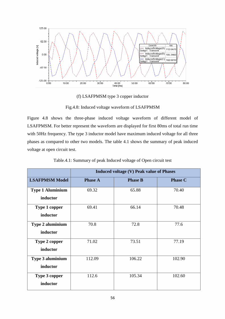
Figure 4.8 shows the three-phase induced voltage waveform of different model of
LSAFPMSM. For better represent the waveform are displayed for first 80ms of total run time
with 50Hz frequency. The type 3 inductor model have maximum induced voltage for all three
phases as compared to other two models. The table 4.1 shows the summary of peak induced
voltage at open circuit test.
Table.4.1: Summary of peak Induced voltage of Open circuit test
Induced voltage (V) Peak value of Phases
LSAFPMSM Model Phase A Phase B Phase C
Type 1 Aluminium
inductor
69.32 65.88 70.40
Type 1 copper
inductor
69.41 66.14 70.48
Type 2 aluminium
inductor
70.8 72.8 77.6
Type 2 copper
inductor
71.02 73.51 77.19
Type 3 aluminium
inductor
112.09 106.22 102.90
Type 3 copper
inductor
112.6 105.34 102.60

57
4.6 Transient analysis
In the transient analysis, the machine is tested under different loading condition. For this
project, the all designed models are tested for no load condition and under load condition at
2Nm. In starting, mechanical load is not given to the machine which means it operate under no
load condition. During the no load condition, the motor performance such as speed, current,
losses, torque, power rating, efficiency and power factor of the machine is tested. But the
efficiency at no load condition is always zero. The next step, 2Nm mechanical load is applied
to machine and the same motor performance is tasted for given load condition. The results of
no load and 2Nm load condition is obtained and represented in graph with respect to time. All
the result of transient analysis is described in the next chapter.

58
Chapter 5: Results and Discussion

59
5.1 Start-up of the Motor
In this section, the speed of the different motor design is examined. It can be also observed the
starting speed of motor in how much time motor reach to 750 rpm and stable average speed.
The first analysis of different motor designs is starting with graph of speed vs time. The
simulation was tested for 1.25 seconds with time step of 2ms. The starting performance of
motor is tested for no load and under load conditions. The moment of inertia 0.01kg m2 was
used for all motor.
Fig.5.1: Speed of induction Motor at no load
The above figure 5.1 indicate the speed vs time graph of the induction motor. The stable
average speed of this motor is 727.41 rpm. Here, stable average is calculated between 0.75s to
1.25s, during this period the speed of the motor is stable. The speed of induction motor is
fluctuating around 750rpm.
Fig.5.2: Speed of LSAFPMSM type 1 aluminium inductor at no load
60
The figure 5.2 shows the speed graph of line-start axial-flux permanent magnet synchronous
motor (LSAFPMSM) with type 1 aluminium inductor at no load. The motor reach to
synchronous speed in very short time 2.8ms. The stable average speed is 750 rpm. This motor
takes less time for stable time as compare to induction motor.
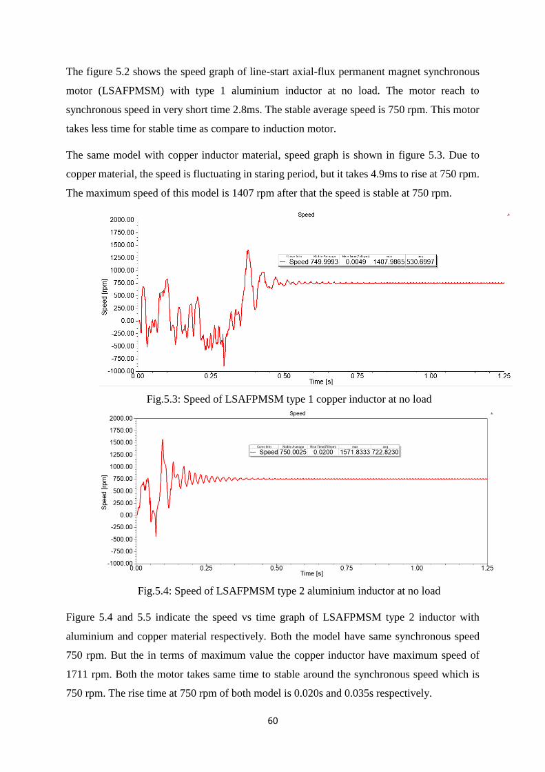
The same model with copper inductor material, speed graph is shown in figure 5.3. Due to
copper material, the speed is fluctuating in staring period, but it takes 4.9ms to rise at 750 rpm.
The maximum speed of this model is 1407 rpm after that the speed is stable at 750 rpm.
Fig.5.3: Speed of LSAFPMSM type 1 copper inductor at no load
Fig.5.4: Speed of LSAFPMSM type 2 aluminium inductor at no load
Figure 5.4 and 5.5 indicate the speed vs time graph of LSAFPMSM type 2 inductor with
aluminium and copper material respectively. Both the model have same synchronous speed
750 rpm. But the in terms of maximum value the copper inductor have maximum speed of
1711 rpm. Both the motor takes same time to stable around the synchronous speed which is
750 rpm. The rise time at 750 rpm of both model is 0.020s and 0.035s respectively.
61
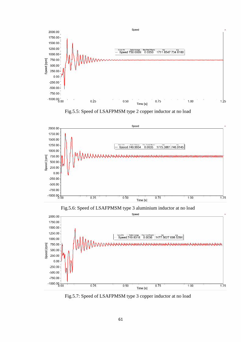
Fig.5.5: Speed of LSAFPMSM type 2 copper inductor at no load
Fig.5.6: Speed of LSAFPMSM type 3 aluminium inductor at no load
Fig.5.7: Speed of LSAFPMSM type 3 copper inductor at no load
62
The Speed plot of LSAFPMSM type 3 inductor with both aluminium and copper material is
shown in figure 5.6 and 5.7. It can be see that; the speed is more fluctuating than other two
models at synchronous speed. But the stable speed is same 750 rpm as other two models.
From the above all speed graph of all model, the speed is 750 rpm for all model. But the speed
of induction motor is fluctuating around 750 rpm. While the type 1 and type 2 model get almost
flat synchronous speed 750 rpm. The induction motor takes more time to become stable speed
while LSAFPMSM takes very less time. The rise time (750 rpm) is also less for LSAFPMSM
as compared to induction motor.
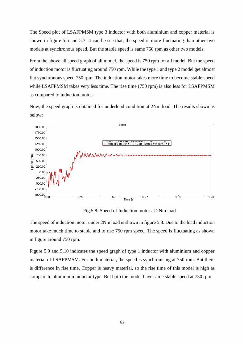
Now, the speed graph is obtained for underload condition at 2Nm load. The results shown as
below:
Fig.5.8: Speed of Induction motor at 2Nm load
The speed of induction motor under 2Nm load is shown in figure 5.8. Due to the load induction
motor take much time to stable and to rise 750 rpm speed. The speed is fluctuating as shown
in figure around 750 rpm.
Figure 5.9 and 5.10 indicates the speed graph of type 1 inductor with aluminium and copper
material of LSAFPMSM. For both material, the speed is synchronising at 750 rpm. But there
is difference in rise time. Copper is heavy material, so the rise time of this model is high as
compare to aluminium inductor type. But both the model have same stable speed at 750 rpm.

63
Fig.5.9: Speed of LSAFPMSM type 1 aluminium inductor at 2Nm load
Fig.5.10: Speed of LSAFPMSM type 1 copper inductor at 2Nm load
Fig.5.11: Speed of LSAFPMSM type 2 aluminium inductor at 2Nm load
64
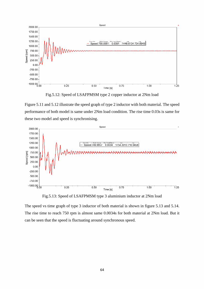
Fig.5.12: Speed of LSAFPMSM type 2 copper inductor at 2Nm load
Figure 5.11 and 5.12 illustrate the speed graph of type 2 inductor with both material. The speed
performance of both model is same under 2Nm load condition. The rise time 0.03s is same for
these two model and speed is synchronising.
Fig.5.13: Speed of LSAFPMSM type 3 aluminium inductor at 2Nm load
The speed vs time graph of type 3 inductor of both material is shown in figure 5.13 and 5.14.
The rise time to reach 750 rpm is almost same 0.0034s for both material at 2Nm load. But it
can be seen that the speed is fluctuating around synchronous speed.

65
Fig.5.14: Speed of LSAFPMSM type 3 copper inductor at 2Nm load
From the above results of speed at no load and 2Nm load, the starting characteristics of
LSAFPMSM models have same as induction motor.
Moreover, speed graph is obtained for full load condition at 14Nm load. The results shown as
below:
Fig.5.15: Speed of Induction motor at 14Nm load
The speed of induction motor at full load condition 14Nm load is shown in figure 5.15. Due to
the full load induction motor take much time to stable and to rise 750 rpm speed. The speed is
fluctuating as shown in figure around 930rpm due to full load 14Nm of motor.
Figure 5.16 and 5.17 indicates the speed graph of type 1 inductor with aluminium and copper
material of LSAFPMSM. For both material, the speed is synchronising at 750 rpm under full
load 14Nm condition.

66
Fig.5.16: Speed of LSAFPMSM type 1 aluminium inductor at 14Nm load
Fig.5.17: Speed of LSAFPMSM type 1 copper inductor at 14Nm load
Fig.5.18: Speed of LSAFPMSM type 2 aluminium inductor at 14Nm load

67
Fig.5.19: Speed of LSAFPMSM type 2 copper inductor at 14Nm load
Fig.5.20: Speed of LSAFPMSM type 3 aluminium inductor at 14Nm load
Fig.5.21: Speed of LSAFPMSM type 3 copper inductor at 14Nm load

68
The advantage of LSAFPMSM model is that it takes less time to reach 750 rpm and also stable
time is very fast as compared to induction motor under loaded conditions. Moreover, under full
load condition 14Nm, the induction motor runs over the synchronous speed while the
LSAFPMSM are running at synchronous speed at 750rpm. Under the any load condition the
LSAFPMSM are running at synchronous speed which is desired to take over induction motor.
So, this kind of motor is run at constant speed which doesn’t required any external circuit drive.
Finally, the LSAFPMSM can be replace to the induction motor for constant speed application.
Table.5.1: Speed response of motor under different load condition
Speed response of motors under different load condition
Load Motor Type Maximum
Speed (rpm)
Steady state
Average
Speed (rpm)
Rise time
(sec) at
750 rpm
No
Load
Induction motor 1149.83 727.41 0.1153
LSAFPMSM
Alu inductor type
1
1171.13 750 0.0028
Copper inductor
type 1
1407.98 750 0.0049
Alu inductor type
2
1571.83 750 0.0200
Copper inductor
type 2
1711.85 750 0.0350
Alu inductor type
3
1775.36 750 0.0035
Copper inductor
type 3
1477.56 750 0.0036
2Nm
load
Induction motor 946.75 749 0.1219
LSAFPMSM
Alu inductor type
1
1610.92 750 0.0040
Copper inductor
type 1
1582.13 750 0.1266

69
Alu inductor type
2
1577.87 750 0.0310
Copper inductor
type 2
1446.61 750 0.0391
Alu inductor type
3
1754.30 750 0.0034
Copper inductor
type 3
1344.87 750 0.0035
Full
load
14Nm
Induction motor 1346.82 938 0.0093
LSAFPMSM
Alu inductor type
1
1506.56 750 0.0147
Copper inductor
type 1
1531.77 750 0.0230
Alu inductor type
2
1570.44 750 0.0115
Copper inductor
type 2
1703.28 750 0.0772
Alu inductor type
3
1637.18 750 0.0018
Copper inductor
type 3
1691.11 750 0.0079

70
5.2 Winding current of Motors
The current of winding is observed in this section. The simulation and test were conducted for
all motor and the winding current of all the motor design was observed. For the batter
performance of the motor, winding current should be sinusoidal waveform. The graph of
current vs time of all model under no load condition is illustrated in figure 5.22.
(a) Winding current for induction motor
(b) Winding current of LSAFPMSM type 1 aluminium inductor

71
(c) Winding current of LSAFPMSM type 1 copper inductor
(d) Winding current of LSAFPMSM type 2 aluminium inductor
(e) Winding current of LSAFPMSM type 2 copper inductor

72
(f) Winding current of LSAFPMSM type 3 aluminium inductor
(g) Winding current of LSAFPMSM type 3 copper inductor
Fig.5.22: Winding current vs Time graph of all model at no load
From the figure 5.22, it can be seen that the winding current of all model is in the balanced
condition. The magnitude and phase shift of all model are in balanced condition. Here, the
stable max current is calculated between the interval of time 0.75s to 1.25s. The stable max
value for all model is ranging between 10 to 15 A winding current for three-phases. The stable
average is average current value between 0.75s to 1.25s. During this period, the winding current
for three-phases almost stable. The stable average value for all model is zero.
If the winding current of motor is unbalanced the main reason is reactance of the three-phase
motor. Due to unbalance winding current, may have adverse effect on efficiency and speed of
motor. It has also bad effect on the torque of motor due to unbalancing of current. The main
reason for motor vibration is unbalance torque which lead motor to damage from connected
73
system. There are also many bad effects on motor due to unbalanced current such as heating
problem and losses of the motor is increase. So, motor cannot be run on the desired output.
But, in this case the winding current of all model are in balanced with magnitude and phase
shift. The motor performance of all model is better which is shown in figure 5.22.
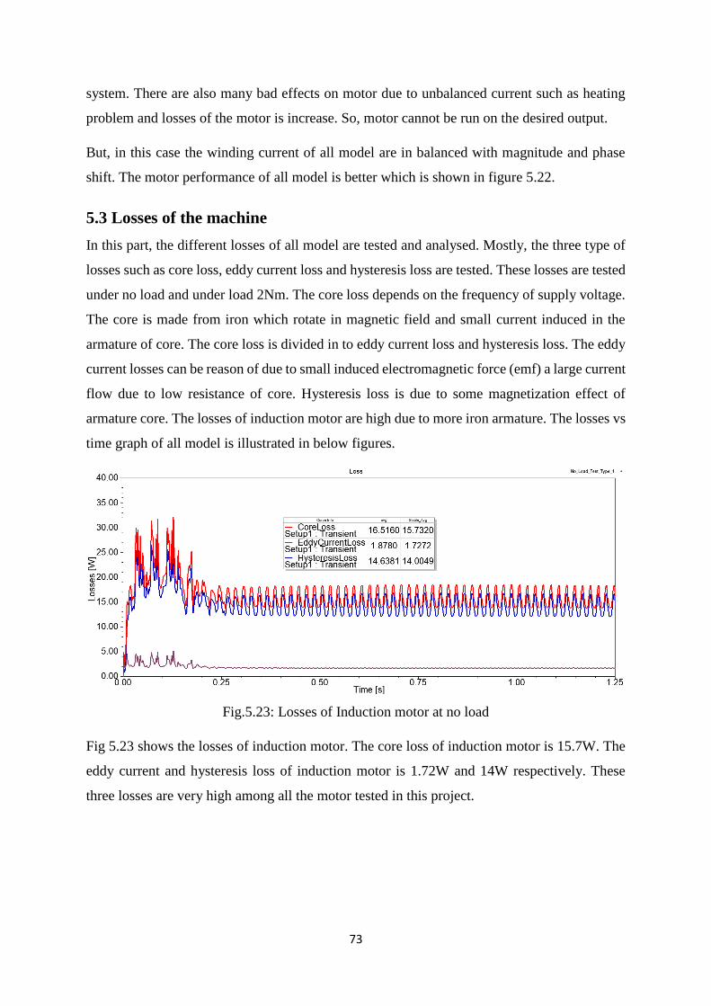
5.3 Losses of the machine
In this part, the different losses of all model are tested and analysed. Mostly, the three type of
losses such as core loss, eddy current loss and hysteresis loss are tested. These losses are tested
under no load and under load 2Nm. The core loss depends on the frequency of supply voltage.
The core is made from iron which rotate in magnetic field and small current induced in the
armature of core. The core loss is divided in to eddy current loss and hysteresis loss. The eddy
current losses can be reason of due to small induced electromagnetic force (emf) a large current
flow due to low resistance of core. Hysteresis loss is due to some magnetization effect of
armature core. The losses of induction motor are high due to more iron armature. The losses vs
time graph of all model is illustrated in below figures.
Fig.5.23: Losses of Induction motor at no load
Fig 5.23 shows the losses of induction motor. The core loss of induction motor is 15.7W. The
eddy current and hysteresis loss of induction motor is 1.72W and 14W respectively. These
three losses are very high among all the motor tested in this project.
74
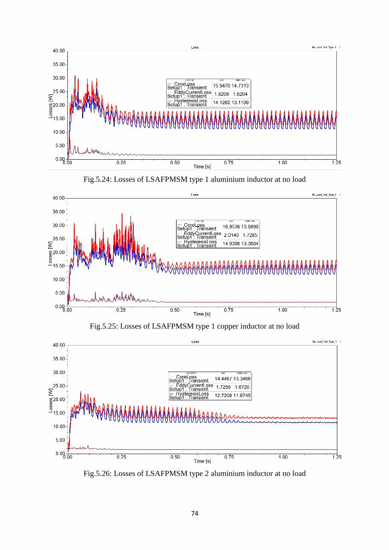
Fig.5.24: Losses of LSAFPMSM type 1 aluminium inductor at no load
Fig.5.25: Losses of LSAFPMSM type 1 copper inductor at no load
Fig.5.26: Losses of LSAFPMSM type 2 aluminium inductor at no load
75
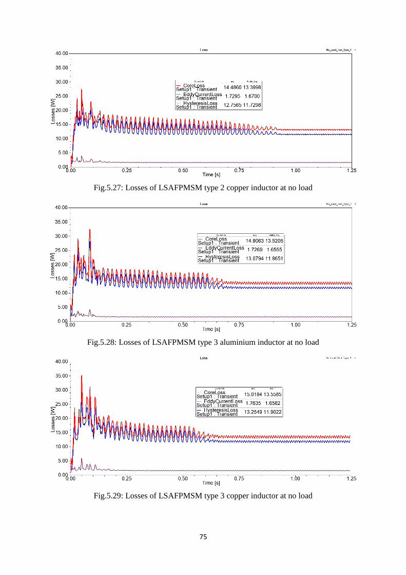
Fig.5.27: Losses of LSAFPMSM type 2 copper inductor at no load
Fig.5.28: Losses of LSAFPMSM type 3 aluminium inductor at no load
Fig.5.29: Losses of LSAFPMSM type 3 copper inductor at no load

76
Figure 5.24 to 5.29 shows the losses of LSAFPMSM for mentioned different design of motors.
The core loss of all LSAFPMSM is around 13.5W except type 1 copper material model. Due
to the copper material, the core loss is high because of mass of material is very high at inductor
and rotor. These all losses are tested at no load condition of motor.
Now, the losses under 2Nm load is tested for all model and graph of losses vs time as flow,
Fig.5.30: Losses of Induction motor at 2Nm load
The losses of induction motor at 2Nm load is shown in figure 5.30. The induction motor has
high core loss of 15.8W as compare to other models. Due to the high losses, the efficiency of
the motor is decrease and power factor is also reduced.
Fig.5.31: Losses of LSAFPMSM type 1 aluminium inductor at 2Nm load
77
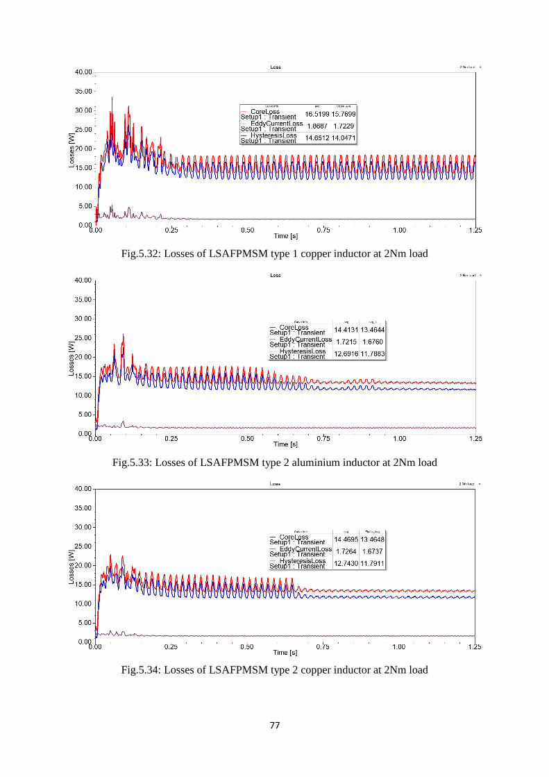
Fig.5.32: Losses of LSAFPMSM type 1 copper inductor at 2Nm load
Fig.5.33: Losses of LSAFPMSM type 2 aluminium inductor at 2Nm load
Fig.5.34: Losses of LSAFPMSM type 2 copper inductor at 2Nm load

78
Fig.5.35: Losses of LSAFPMSM type 3 aluminium inductor at 2Nm load
Fig.5.36: Losses of LSAFPMSM type 3 copper inductor at 2Nm load
From the above results of losses at no load and 2Nm load, it can be seen that the induction
motor has very high losses as compared to LSAFPMSM. The average core losses of induction
motor are 16.5W and the losses in other models are average of 13.5W. Due to the less losses
the efficiency of LSAFPMSM becomes high as compared to induction motor.

79
5.4 Torque produced by Machine
In this section, the performance of torque is studied for all design motor. Torque is produced
due to rotating force to radius of machine. The motor start from zero to maximum speed, during
this period torque is developed. Here, the torque plot is obtained to check the starting torque
performance of motor. The torque studied under no load condition and with 2Nm load. The
graph of torque vs time is listed below.
Fig.5.37: Torque of Induction motor at no load
Fig.5.38: Torque of LSAFPMSM type 1 aluminium inductor at no load
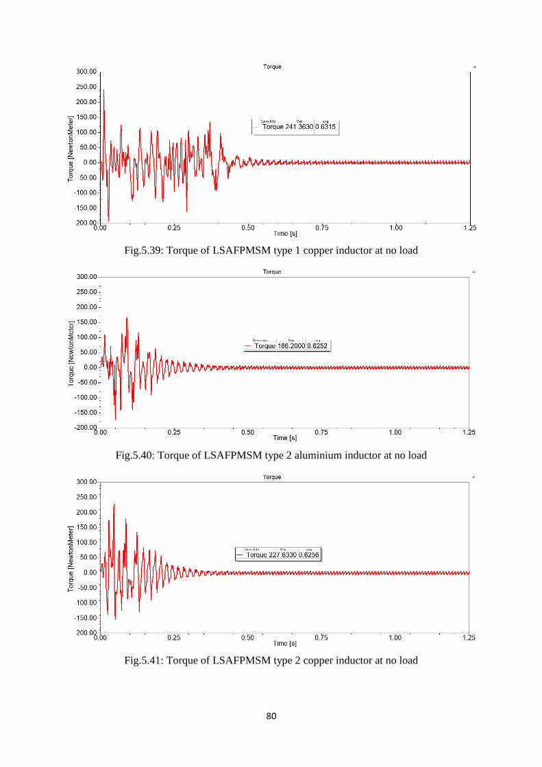
80
Fig.5.39: Torque of LSAFPMSM type 1 copper inductor at no load
Fig.5.40: Torque of LSAFPMSM type 2 aluminium inductor at no load
Fig.5.41: Torque of LSAFPMSM type 2 copper inductor at no load
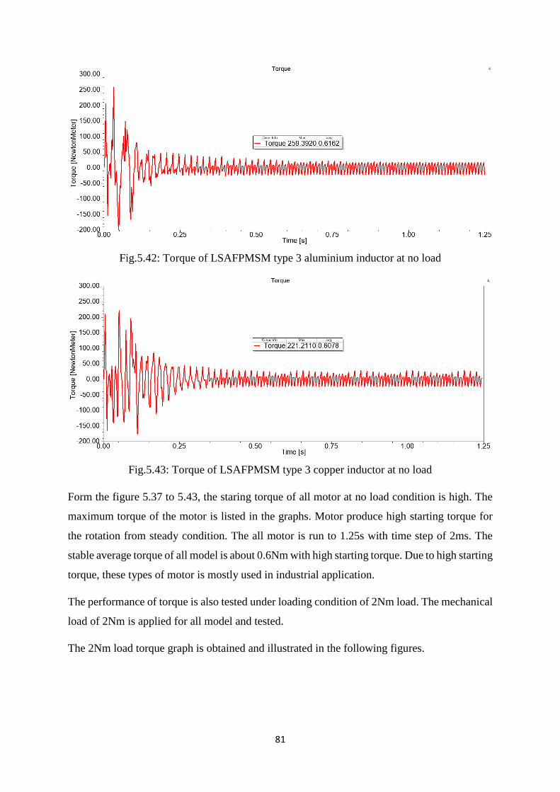
81
Fig.5.42: Torque of LSAFPMSM type 3 aluminium inductor at no load
Fig.5.43: Torque of LSAFPMSM type 3 copper inductor at no load
Form the figure 5.37 to 5.43, the staring torque of all motor at no load condition is high. The
maximum torque of the motor is listed in the graphs. Motor produce high starting torque for
the rotation from steady condition. The all motor is run to 1.25s with time step of 2ms. The
stable average torque of all model is about 0.6Nm with high starting torque. Due to high starting
torque, these types of motor is mostly used in industrial application.
The performance of torque is also tested under loading condition of 2Nm load. The mechanical
load of 2Nm is applied for all model and tested.
The 2Nm load torque graph is obtained and illustrated in the following figures.

82
Fig.5.44: Torque of Induction motor at 2Nm
Fig.5.45: Torque of LSAFPMSM type 1 aluminium inductor at 2Nm
Fig.5.46: Torque of LSAFPMSM type 1 copper inductor at 2Nm

83
Fig.5.47: Torque of LSAFPMSM type 2 aluminium inductor at 2Nm
Fig.5.48: Torque of LSAFPMSM type 2 copper inductor at 2Nm
Fig.5.49: Torque of LSAFPMSM type 3 aluminium inductor at 2Nm
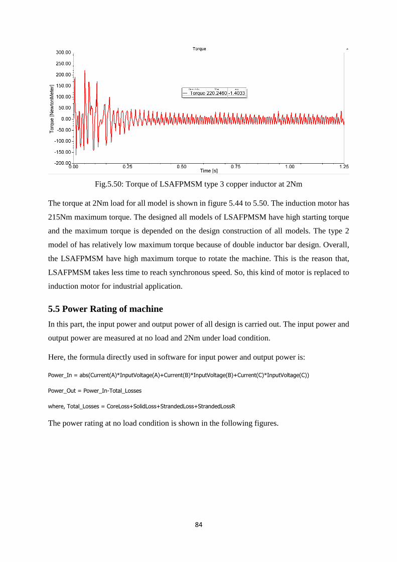
84
Fig.5.50: Torque of LSAFPMSM type 3 copper inductor at 2Nm
The torque at 2Nm load for all model is shown in figure 5.44 to 5.50. The induction motor has
215Nm maximum torque. The designed all models of LSAFPMSM have high starting torque
and the maximum torque is depended on the design construction of all models. The type 2
model of has relatively low maximum torque because of double inductor bar design. Overall,
the LSAFPMSM have high maximum torque to rotate the machine. This is the reason that,
LSAFPMSM takes less time to reach synchronous speed. So, this kind of motor is replaced to
induction motor for industrial application.
5.5 Power Rating of machine
In this part, the input power and output power of all design is carried out. The input power and
output power are measured at no load and 2Nm under load condition.
Here, the formula directly used in software for input power and output power is:
Power_In = abs(Current(A)*InputVoltage(A)+Current(B)*InputVoltage(B)+Current(C)*InputVoltage(C))
Power_Out = Power_In-Total_Losses
where, Total_Losses = CoreLoss+SolidLoss+StrandedLoss+StrandedLossR
The power rating at no load condition is shown in the following figures.

85
Fig.5.51: Input and output power of Induction motor at no load
Fig.5.52: Input and output power of LSAFPMSM type 1 aluminium inductor at no load
Fig.5.53: Input and output power of LSAFPMSM type 1 copper inductor at no load
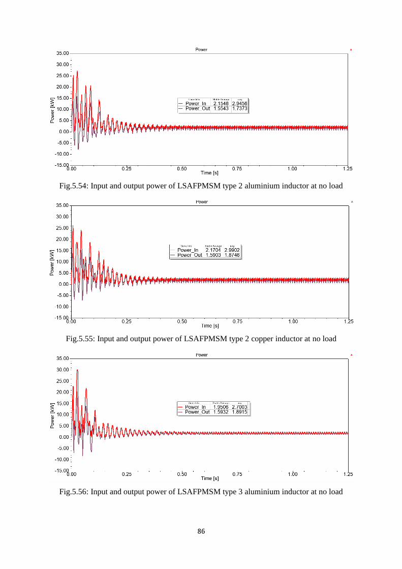
86
Fig.5.54: Input and output power of LSAFPMSM type 2 aluminium inductor at no load
Fig.5.55: Input and output power of LSAFPMSM type 2 copper inductor at no load
Fig.5.56: Input and output power of LSAFPMSM type 3 aluminium inductor at no load

87
Fig.5.57: Input and output power of LSAFPMSM type 3 copper inductor at no load
The input and output power of induction motor is low as compared to LSAFPMSM in figure
5.51. The input and output power of LSAFPMSM type 1 and type 3 has almost same value as
input power of 1.9kW and output power is 1.6kW. This is because the same design of inductor
with different position on the rotor. While, the type 2 motor has input power 2.1kW and output
power is 1.5kW because of double inductor design as discussed in design chapter. So, at no
load LSAFPMSM have high power rating as compared to induction motor.
In the second part, the input power and output power are tested for 2Nm under load condition
and the graph for given load is as following.
Fig.5.58: Input and output power of Induction motor at 2Nm load

88
Fig.5.59: Input and output power of LSAFPMSM type 1 aluminium inductor at 2Nm load
Fig.5.60: Input and output power of LSAFPMSM type 1 copper inductor at 2Nm load
Fig.5.61: Input and output power of LSAFPMSM type 2 aluminium inductor at 2Nm load

89
Fig.5.62: Input and output power of LSAFPMSM type 2 copper inductor at 2Nm load
Fig.5.63: Input and output power of LSAFPMSM type 3 aluminium inductor at 2Nm load
Fig.5.64: Input and output power of LSAFPMSM type 3 copper inductor at 2Nm load

90
At 2Nm load, the output power of induction motor 1.3kW. The LSAFPMSM have relatively
high output power as compared to induction motor. The all models of LSAFPMSM have almost
same 1.5kW output power as indicated in the above graphs. This value of input power and
output power are used to calculate the efficiency of motors.
5.6 Efficiency of motor
The ratio between output power to input power is called efficiency. In this section, the
efficiency of all model motor is obtained. The efficiency of motor is depended on the design,
construction, power rating, load and construction of motor. For this project, the efficiency of
all model is calculated manually.
The efficiency of the motor at no load is zero. The under 2Nm load condition the efficiency of
all models are shown in figure 5.65.
Fig.5.65: Efficiency of all motors at 2Nm load
Form the results, it can be seen that the all new design models of line-start axial-flux permanent
magnet synchronous motor has higher efficiency. The new LSAFPMSM has around 83%
efficiency of all models at 2Nm load. While, the efficiency of the induction motor is 72% at
2Nm load. Due to higher efficiency, this kind of motor is used for industrial purpose to
overcome the disadvantages of the induction motor.
0.00%
10.00%
20.00%
30.00%
40.00%
50.00%
60.00%
70.00%
80.00%
90.00%
100.00%
IM LSAFPMSMAlu
Inductortype 1
LSAFPMSMCopper
inductortype 1
LSAFPMSMAlu
Inductortype 2
LSAFPMSMCopper
inductortype 2
LSAFPMSMAlu
Inductortype 3
LSAFPMSMCopper
inductortype 3
Efficiency

91
5.7 Power Factor
Power factor is one of the important factor of the motor. The energy cost of motor can be
reduced by improving the power factor. Sometimes, power factor is overlook while designing
of the motor which causes higher cost of motor. Normally, the power factor is defined as ration
of kilowatts (kW) and kilovolt-amp (KVA). It is also defined as phase angle between voltage
and current.
The formula which is used to calculate power factor in software is given below.
Power_Factor = (Mechanical_Power)/Power_In
Where, Mechanical_Power = Power_In-Electrical_Loss
The Power factor of all motor is illustrated in the following figure 5.66.
Fig.5.66: Power factor of motor at no load and 2Nm load
The power factor of induction motor at no load is 0.79 and 0.8 at 2Nm load. On the other side,
the new developed models of LSAFPMSM have higher power factor at no load and at 2Nm
load as compared to induction motor. The type 1 model has 0.88 and 0.89 power factor at no
load and 2 Nm load. Type 2 model has low power factor among the three models of
LSAFPMSM but higher power factor than induction motor.
0.7
9 0.8
8
0.8
7
0.8
2
0.8
2
0.8
6
0.8
6
0.8
0.8
9
0.8
8
0.8
2
0.8
3
0.8
5
0.8
5
I M L S A F P M S M A L U
I N D U C T O R T Y P E 1
L S A F P M S M C O P P E R
I N D U C T O R T Y P E 1
L S A F P M S M A L U
I N D U C T O R T Y P E 2
L S A F P M S M C O P P E R
I N D U C T O R T Y P E 2
L S A F P M S M A L U
I N D U C T O R T Y P E 3
L S A F P M S M C O P P E R
I N D U C T O R T Y P E 3
POWER FACTOR
No load 2Nm Load

92
Table.5.2: Overall performance of all motors
Line-start Axial flux permanent magnet synchronous motor
Induction
motor
Alu type
1
inductor
Copper
type 1
inductor
Alu type
2
inductor
Copper
type 2
inductor
Alu type
3
inductor
Copper
type 3
inductor
Speed
(rpm)
727 750 750 750 750 750 750
Rated
Output
power
(kW)
1.1 1.5 1.5 1.49 1.49 1.5 1.5
Number
of pole
8 8 8 8 8 8 8
Frequency
(Hz)
50 50 50 50 50 50 50
Airgap
(mm)
1 1 1 1 1 1 1
Losses
(W)
16.5 15.9 16.5 14.4 14.4 13.6 13.6
Efficiency
(%)
72 84.16 83.55 79.05 78.7 83.33 83.33
Table 5.2 shows the overall performance of the all motors. The line-start axial flux permanent
magnet synchronous motor (LSAFPMSM) has better performance as compared to induction
motor. The constant synchronous speed is achieved in all models of LSAFPMSM. This motor
has less losses as compared to induction motor which leads to better efficiency of the motor.
The 1mm air gap is selected for all motors and supply frequency 50Hz. LSAFPMSM models
have higher output power at no load and at 2Nm load. At last, the LSAFPMSM have higher
efficiency than induction motor at 2Nm load. So, this kind of motor replace induction motor
for industrial application. The LSAFPMSM does not require any external circuit to start the
motor. It is directly work on three-phase supply voltage.
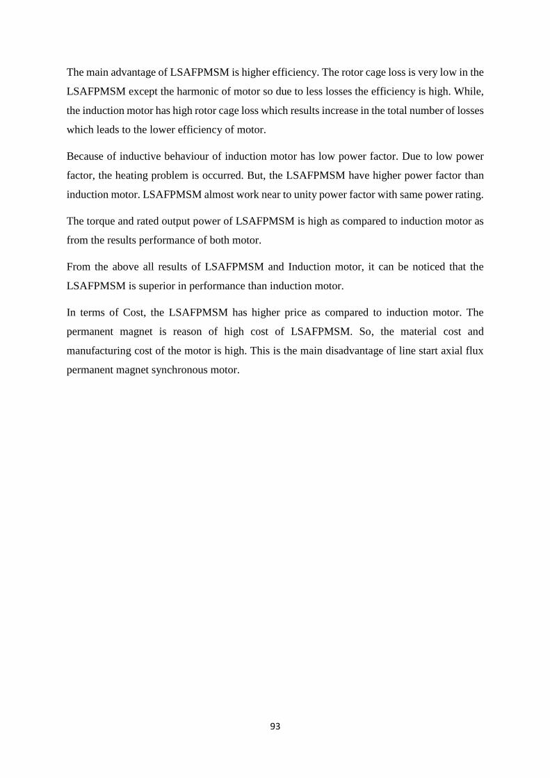
93
The main advantage of LSAFPMSM is higher efficiency. The rotor cage loss is very low in the
LSAFPMSM except the harmonic of motor so due to less losses the efficiency is high. While,
the induction motor has high rotor cage loss which results increase in the total number of losses
which leads to the lower efficiency of motor.
Because of inductive behaviour of induction motor has low power factor. Due to low power
factor, the heating problem is occurred. But, the LSAFPMSM have higher power factor than
induction motor. LSAFPMSM almost work near to unity power factor with same power rating.
The torque and rated output power of LSAFPMSM is high as compared to induction motor as
from the results performance of both motor.
From the above all results of LSAFPMSM and Induction motor, it can be noticed that the
LSAFPMSM is superior in performance than induction motor.
In terms of Cost, the LSAFPMSM has higher price as compared to induction motor. The
permanent magnet is reason of high cost of LSAFPMSM. So, the material cost and
manufacturing cost of the motor is high. This is the main disadvantage of line start axial flux
permanent magnet synchronous motor.

94
Chapter 6: Conclusion and Future work
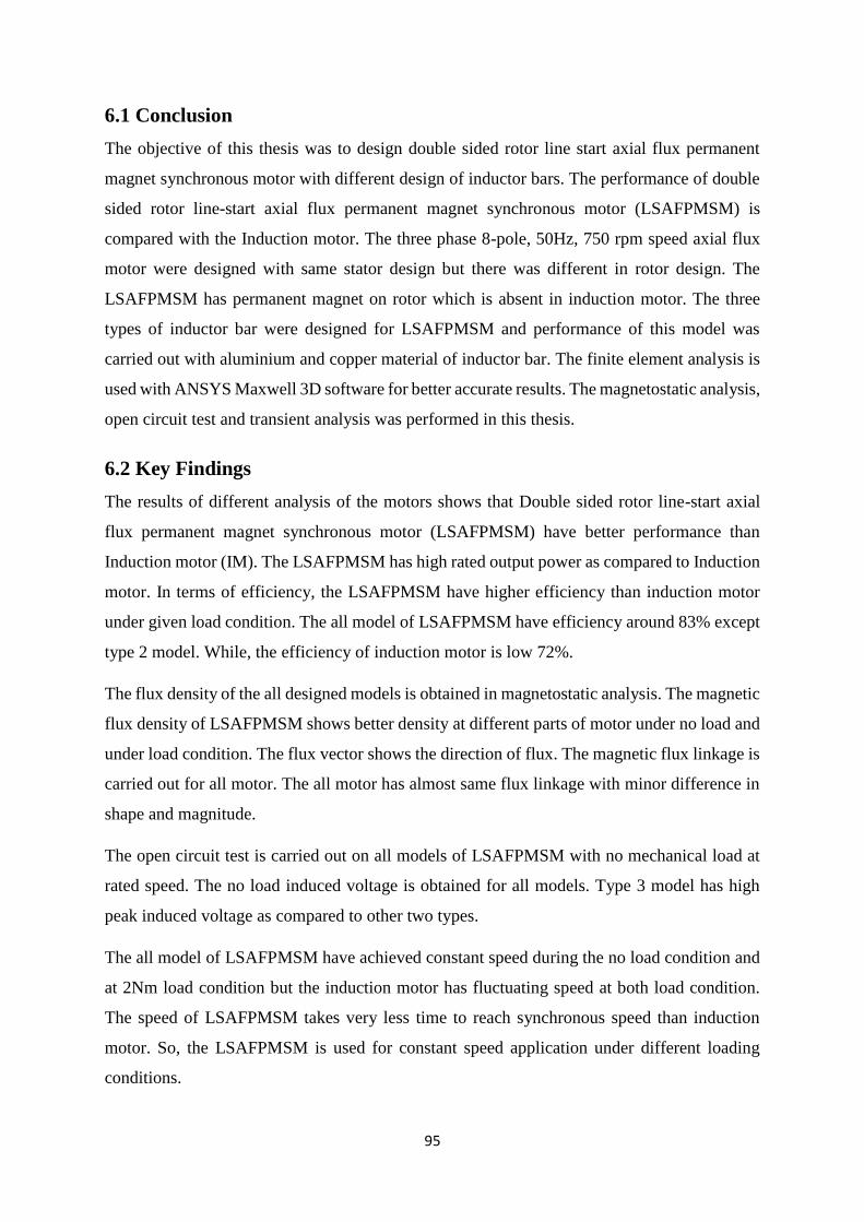
95
6.1 Conclusion
The objective of this thesis was to design double sided rotor line start axial flux permanent
magnet synchronous motor with different design of inductor bars. The performance of double
sided rotor line-start axial flux permanent magnet synchronous motor (LSAFPMSM) is
compared with the Induction motor. The three phase 8-pole, 50Hz, 750 rpm speed axial flux
motor were designed with same stator design but there was different in rotor design. The
LSAFPMSM has permanent magnet on rotor which is absent in induction motor. The three
types of inductor bar were designed for LSAFPMSM and performance of this model was
carried out with aluminium and copper material of inductor bar. The finite element analysis is
used with ANSYS Maxwell 3D software for better accurate results. The magnetostatic analysis,
open circuit test and transient analysis was performed in this thesis.
6.2 Key Findings
The results of different analysis of the motors shows that Double sided rotor line-start axial
flux permanent magnet synchronous motor (LSAFPMSM) have better performance than
Induction motor (IM). The LSAFPMSM has high rated output power as compared to Induction
motor. In terms of efficiency, the LSAFPMSM have higher efficiency than induction motor
under given load condition. The all model of LSAFPMSM have efficiency around 83% except
type 2 model. While, the efficiency of induction motor is low 72%.
The flux density of the all designed models is obtained in magnetostatic analysis. The magnetic
flux density of LSAFPMSM shows better density at different parts of motor under no load and
under load condition. The flux vector shows the direction of flux. The magnetic flux linkage is
carried out for all motor. The all motor has almost same flux linkage with minor difference in
shape and magnitude.
The open circuit test is carried out on all models of LSAFPMSM with no mechanical load at
rated speed. The no load induced voltage is obtained for all models. Type 3 model has high
peak induced voltage as compared to other two types.
The all model of LSAFPMSM have achieved constant speed during the no load condition and
at 2Nm load condition but the induction motor has fluctuating speed at both load condition.
The speed of LSAFPMSM takes very less time to reach synchronous speed than induction
motor. So, the LSAFPMSM is used for constant speed application under different loading
conditions.

96
Starting torque of the LSAFPMSM is high as compared to Induction motor. Due to high
starting torque response, the rotation of motor start very fast. After that, torque is stable at
around 0Nm for all model. The core loss of the induction motor is high as compared to
LSAFPMSM at no load and at 2Nm load.
The rated output power of all models of LSAFPMSM is high as compared to Induction motor.
The LSAFPMSM models have 1.5kW rated output power. The induction motor obtained
1.1kW output power.
As mentioned before, the LSAFPMSM has better efficiency than induction motor. The power
factor is also improved for LSAFPMSM models as compared to Induction motor. Due to high
efficiency and constant speed, LSAFPMSM is suitable to replace induction motor for industrial
application. The drawback of LSAFPMSM is the cost. The cost of LSAFPMSM is high
because of permanent magnet used in rotor.
6.3 Future work
Optimisation of design
This thesis discussed the design and performance of double sided rotor line start axial flux
permanent magnet synchronous motor with three type of inductor bar design. In the future, the
performance of motor can be optimized by changing the shape and size of magnets, different
arrangement of inductor bar and by changing the winding properties.
Prototyping
The working models of LSAFPMSM can be optimised in future for better accurate and actual
experimental results.
97
References
[1] Energy Efficiency Series, “Energy-Efficiency policy opportunity for electric Motor-
Driven System”. Accessed on: 08 October 2017, Online available at:
http://citeseerx.ist.psu.edu/viewdoc/download?doi=10.1.1.378.4854&rep=rep1&type=pdf
[2] Electric Motors, “Energy Rating, Accessed: 08 October 2017,
< http://www.energyrating.gov.au/products/electric-motors#toc2 >
[3] L. Livadaru, A. Simion, A. Munteanu and O. Dabija, “Design and FEM based Simulation
of High Power Induction Motor with severe Start-up Constraints”, AGIR, Romania, Tech. Rep.
101-106, 2012. [Online]. Available: http://www.agir.ro/buletine/1521.pdf.
[4] S. Contreras, C. Cortes, M. Guzman, “Modelling of squirrel cage induction motors for a
bio-inspired multi-objective optimal design”, IET Electr. Power appl. 2017. Iss 4, pp. 512-523.
[5] Ruthes, J.R., Nau, S.L. and Nied, A., 2016, November. “Performance analysis of induction
motor under non-sinusoidal supply voltages”. In Industry Applications (INDUSCON), 2016
12th IEEE International Conference on (pp. 1-6). IEEE.
[6] Srinivasan, J., Selvaraj, K., Chitrarasu, J. and Resmi, R., 2016, October. Design and analysis
of squirrel cage induction motor in short pitch and full pitch winding configurations using FEA.
In Emerging Technological Trends (ICETT), International Conference on (pp. 1-10). IEEE.
[7] Pyrhonen J, Jokinen T and Hrabovcova V, “Design of Rotating Electrical Machines”, 2nd
ed. Chichester, United Kingdom: Wiley, 2014, pp. 293-456
[8] Cavagnino, A., Lazzari, M., Profumo, F. and Tenconi, A., 2002. A comparison between the
axial flux and the radial flux structures for PM synchronous motors. IEEE Transactions on
Industry Applications, 38(6), pp.1517-1524.
[9] Patterson, D.J., Colton, J.L., Mularcik, B., Kennedy, B.J., Camilleri, S. and Rohoza, R.,
2009, May. A comparison of radial and axial flux structures in electrical machines. In Electric
Machines and Drives Conference, 2009. IEMDC'09. IEEE International (pp. 1029-1035).
IEEE.
[10] Upadhyay, P.R. and Rajagopal, K.R., 2005. Comparison of performance of the axial-field
and radial-field permanent magnet brushless direct current motors using computer aided design
and finite element methods. Journal of applied physics, 97(10), p.10Q506.
98
[11] Sitapati, K. and Krishnan, R., 2001. Performance comparisons of radial and axial field,
permanent-magnet, brushless machines. IEEE Transactions on industry applications, 37(5),
pp.1219-1226.
[12] Parviainen, A., Niemela, M., Pyrhonen, J. and Mantere, J., 2005, May. Performance
comparison between low-speed axial-flux and radial-flux permanent-magnet machines
including mechanical constraints. In Electric Machines and Drives, 2005 IEEE International
Conference on (pp. 1695-1702). IEEE.
[13] Mahmoudi, A., Kahourzade, S., Uddin, M.N., Rahim, N.A. and Hew, W.P., 2013,
September. Line-start axial-flux permanent-magnet synchronous motor. In Energy Conversion
Congress and Exposition (ECCE), 2013 IEEE (pp. 3210-3216). IEEE.
[14] Ugale, R.T., Bhanuji, A. and Chaudhari, B.N., 2009, January. A novel line start permanent
magnet synchronous motor using two-part rotor. In TENCON 2009-2009 IEEE Region 10
Conference (pp. 1-5). IEEE.
[15] Tsuboi, K., Takegami, T., Hirotsuka, I. and Nakamura, M., 2011. A general analytical
method for a three-phase line-start permanent-magnet synchronous motor. IEEJ Transactions
on Industry Applications, 131, pp.692-699.
[16] Feng, X., Bao, Y., Liu, L., Huang, L. and Zhang, Y., 2012, September. Performance
investigation and comparison of line start-up permanent magnet synchronous motor with super
premium efficiency. In Electrical Machines (ICEM), 2012 XXth International Conference
on (pp. 424-429). IEEE.
[17] Fei, W., Luk, P.C.K., Ma, J., Shen, J.X. and Yang, G., 2009. A high-performance line-
start permanent magnet synchronous motor amended from a small industrial three-phase
induction motor. IEEE Transactions on Magnetics, 45(10), pp.4724-4727.
[18] Kül, S., Bilgin, O. and Mutluer, M., 2015. Application of finite element method to
determine the performances of the line start permanent magnet synchronous motor. Procedia-
Social and Behavioral Sciences, 195, pp.2586-2591.

99
Appendices
Appendix A: Mesh plots
Mesh plot of LSAFPMSM type 1 Alu inductor
Mesh plot of LSAFPMSM type 1 copper inductor
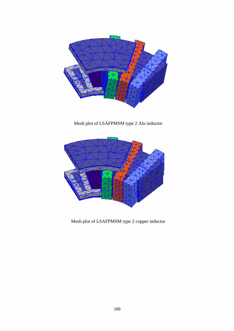
100
Mesh plot of LSAFPMSM type 2 Alu inductor
Mesh plot of LSAFPMSM type 2 copper inductor

101
Mesh plot of LSAFPMSM type 3 Alu inductor
Mesh plot of LSAFPMSM type 3 copper inductor