Embed Size (px)
Citation preview

International Journal of Advance Research, IJOAR .org ISSN 2320-9186 1
IJOAR© 2013 http://www.ijoar.org
International Journal of Advance Research, IJOAR .org Volume 1, Issue 7, July 2013, Online: ISSN 2320-9186
DESIGN AND ANALYSIS OF WING FUSELAGE INTERSECTION FOR FATIGUE
AND SELF-HEALING TECHNIQUE Md Akhtar Khan1, M Kiran2,K Kelvin James3
[email protected], [email protected], [email protected] 1.Assistant Professor Gitam University, Hyderabad 2.Aeronautical engineering student of Guru Nanak Institutions Technical Campus, Hyderabad,3. Aeronautical engineering student of Guru Nanak Institutions Technical Campus, Hyderabad.
Abstract- The drag which exists due to interaction of wing- fuselage section is called as Interference drag. High interference drag may lead to Fatigue which is progressive a failure mechanism and material degradation. The degradation or damage accumulation progresses until a finite crack is nucleated. The objective is to design a Fail-Safe Structural component and do the stress analysis and introducing carbon nano tubes in the structure for the self-healing process which is the modern technique to detect and heal the cracks. We have designed a Wing-Bracket attachment and done the analysis of wing-fuselage interaction using Ansys. We have represented Goodman diagram for Maraging steel and explained the methodology of Self- healing technique .The flow over the wing is accelerated such that aerodynamic interference between the wing and fuselage is critical in transonic flight regime, which may leads to structural failure
Keywords: —
Aircraft, Fatigue, CATIA V5, Stress, strain, Airfoil, wing bracket, Interference drag, Ansys, Gambit

International Journal of Advance Research, IJOAR .org ISSN 2320-9186 2
IJOAR© 2013 http://www.ijoar.org
Introduction
The purpose of aerodynamic analysis of an
airplane is to optimize aerodynamic
performance. That is to maximize lift for a given
amount of drag, and conversely to minimize
drag for a given amount of lift. Shapes and
contours of individual components and parts on
aircraft affect the amount of total aircraft drag.
Nevertheless, the total drag further rises when
combining these parts into an airplane. This
increment in drag is called interference drag [1].
The performance of the aircraft depends on the
life span of the different components. At some
number of cycles each and every component
undergoes damage. Structure of an aircraft will
resist different types of loads in different
conditions. Weight also plays an important role
in performance and life span of the aircraft. All
of these investigations indicate that there is a
possibility that the drag-rise characteristics can
be improved by taking advantage of a favorable
interference between two components and that
the drag-divergence Mach number can be
increased [2]. Aircraft structure damages due to
the application of different cyclic loads at
different segments of its Flight. The interference
effects that occur for several wing-body
geometries that are considered candidates for a
design of an airplane intended to operate at low
subsonic speeds at high altitude. Due to
continuous applications of loads the structure
degrades. This degradation of structure due to
application of cyclic loads is called fatigue
analysis. Each and every component of an
aircraft undergoes fatigue damage. Now our
next step is to select the component which
undergoes fatigue damage. Fatigue is a type of
fracture that occurs in materials that are
subjected to changing or varying stresses over
time. Fatigue occurs when a material is
subjected to repeat loading and unloading. If the
loads are above a certain threshold, microscopic
cracks will begin to form at the stress
concentrators such as the surface, persistent slip
bands (PSBs), and grain interfaces. Eventually a
crack will reach a critical size, and the structure
will suddenly fracture
The Advancement in technology made the
structure of composite materials stronger than
they actually needed to be, so when the damage
occurs it will less likely to be catastrophic. This
can be equally required for a composite material
if the crack is detected that could heal itself,
without the help of human interaction, These
composite materials have made a good impact
on automobiles and aircraft structures [3]. Crack
formatted due to the heavy aerodynamic flow
and gust loads areas which highly effected in
aircraft structures are wings, control surfaces,
and rudder
Wings: This are highly effected due to
aerodynamic flow and fatigue, gust loads have a
great impact on the wing structure. The first of
these is the heating up and cooling down of the
Aircraft surface during each supersonic flight
which induces a thermal stress cycle
contributing to the general Fatigue damage and
critically affecting design at some locations.
Same with the control surface and rudder
Different phases of the fatigue life The fatigue life is usually split into a crack
initiation period and a crack growth period:-
Crack initiation
This is the initial stage of the fatigue crack may be
caused by surface scratches caused by handling, or
tooling of the material. Cracks also generally
originate from a geometrical discontinuity or
metallurgical stress raiser like sites of inclusions.
Crack growth
This further increases the stress levels and the
process continues, propagating the cracks across
the grains or along the grain boundaries, slowly
increasing the crack size. As the size of the crack
increases the cross sectional area resisting the
applied stress decreases and reaches a thresh hold
level at which it is insufficient to resist the applied
stress. Crack growth resistance when the crack
penetrates into the material depends on the
International Journal of Advance Research, IJOAR .org ISSN 2320-9186 3
IJOAR© 2013 http://www.ijoar.org
material as a bulk property. Crack growth is no
longer a surface phenomenon. The crack continues
to grow during this stage as a result of
continuously applied stresses. Failure occurs when
the material that has not been affected by the crack
cannot withstand the applied stress.
Safe-life design
Safe-life design is based on the assumption that the
part is initially flaw-free and has a fine life in
which to develop a critical crack size.
Fail-safe design
The fail-safe design philosophy assumes that
fatigue cracks will be detected and repaired before
they lead to failure.
Mean Stress Consideration The standard S-N Curve used for fatigue
calculations is based on pure alternating load.
Mean stress for this test is zero. Mean stress would
be present for all the loading conditions other than
pure alternating. It is also generated due to
processes like rolling or heat treatment, bolt pre-
stresses or constant loading applications.
Strain-Life Approach (E - N)
Strain life approach is also known as Crack
Initiation approach. This method calculates crack
initiation life. It is considered for plastic strain and
recommended to Low Cycle fatigue.
In the High Cycle fatigue region, stress and strain
levels are low and they are linearly related.
Traditionally, the magnitude of the observed cyclic
stresses were observed to be less than the tensile
elastic limit and the lives long (i.e., greater than
about 105 cycles). This pattern of behavior has
become known as high-cycle fatigue.
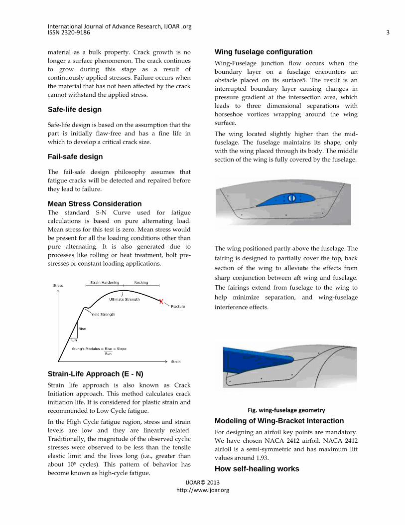
Wing fuselage configuration
Wing-Fuselage junction flow occurs when the
boundary layer on a fuselage encounters an
obstacle placed on its surface5. The result is an
interrupted boundary layer causing changes in
pressure gradient at the intersection area, which
leads to three dimensional separations with
horseshoe vortices wrapping around the wing
surface.
The wing located slightly higher than the mid-
fuselage. The fuselage maintains its shape, only
with the wing placed through its body. The middle
section of the wing is fully covered by the fuselage.
The wing positioned partly above the fuselage. The
fairing is designed to partially cover the top, back
section of the wing to alleviate the effects from
sharp conjunction between aft wing and fuselage.
The fairings extend from fuselage to the wing to
help minimize separation, and wing-fuselage
interference effects.
Fig. wing-fuselage geometry
Modeling of Wing-Bracket Interaction
For designing an airfoil key points are mandatory.
We have chosen NACA 2412 airfoil. NACA 2412
airfoil is a semi-symmetric and has maximum lift
values around 1.93.
How self-healing works

International Journal of Advance Research, IJOAR .org ISSN 2320-9186 4
IJOAR© 2013 http://www.ijoar.org
Carbon nanotubes are allotropes of carbon with a
cylindrical nanostructures. These cylindrical
carbon molecules have unusual properties like
thermal conductivity and mechanical and electrical
properties. By implanting a polymer with
electrically conductive carbon nanotubes, and then
monitoring of the structure’s which are electrically
resistive, Once a crack is identified, then we can
send a short electric charge to the area in order to
heat up the carbon nanotubes and in turn melt an
embedded healing agent that will flow into and
seal the crack with a 70 percent recovery in
strength
A structure from common epoxy, this kind is used
to manufacture everything from the lightweight
frames of fighter jet wings to countless devices and
components used in manufacturing but they
added enough of multiwalled carbon nanotubes to
comprise 1 percent of the structure’s total weight.
They mechanically mix some liquid poxy to ensure
the carbon nanotubes were properly dispersed
throughout the structure as it dried in a mold.
When the composite structure are introduced with
a series of wires in the form of a grid, which can be
used to measure electrically resistive and also
apply control voltages to the structure. By giving a
small amount of electricity through the carbon
nanotubes, the research team could be able to
measure the electrical resistance between any two
points on the wire grid. Then they create a tiny
crack in the structure, and measured the electrical
resistance in between two nearest grid points.
Hence the electrical current has to travel around
the crack to get from one point to another, the
electrical resistance. As longer as the crack grew,
electrical resistance between the two points
increased.
Self-healing agents
Development of submicron capsules and nano
capsules filled with healing agent will allow for the
incorporation of healing functionality in
composites
with interstitial spacing smaller than capsules
prepared using previous methods. Submicron
capsules and particles have been prepared
previously for encapsulation of inorganic particles
such as magnetite in polystyrene [6], pressure
sensitive adhesives [7], and melamine-
formaldehyde capsules containing cyclohexane
and n-octadecane [8].
The process of in situ polymerization has been
used to produce microcapsules as described in the
previous works of Brown et al. [5], Ni et al. [7], and
Alexandridrou et al. [11]. The addition of
particulate fillers, such as capsules, to an epoxy
resin can have a significant influence on the
mechanical properties of a material.
Importing key points into CATIA using EXCEL sheet

International Journal of Advance Research, IJOAR .org ISSN 2320-9186 5
IJOAR© 2013 http://www.ijoar.org
Extruding key points
Next exit the work bench and use PAD option to
add material along perpendicular direction
(EXTRUDE). Thickness of the airfoil we have
chosen here is 0.2mm.
Giving Holes In sketcher, using circle and constraints three
circles are drawn on airfoil. Distance between holes
is maintained 0.25mm. Hole diameter are 0.05mm,
0.04mm, 0.03mm respectively.
Modeling of Stringers
In this section we first draw circle with 0.05mm
diameter. By using PAD option in part design we
extrude these circles to a length 1.75mm cylinder.
These cylinders represent stringers in actual
aircraft.
Assembling of stringers with NACA 2412
Airfoils
To combine the parts we use assembly work bench.
We insert each part one by one. Initially we
inserted 0.05 mm cylinder using “Insert existing
part with position”. By using coincidence
command gave coincidence between the airfoil
0.05mm hole and cylinder
International Journal of Advance Research, IJOAR .org ISSN 2320-9186 6
IJOAR© 2013 http://www.ijoar.org
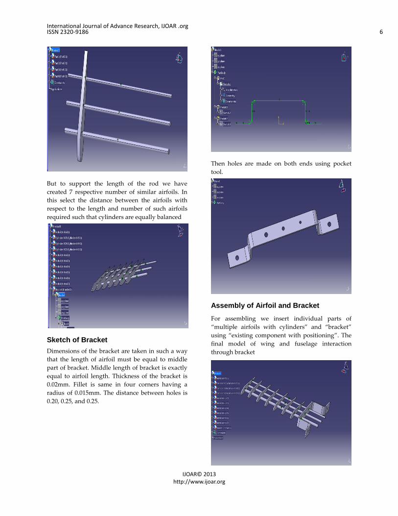
But to support the length of the rod we have
created 7 respective number of similar airfoils. In
this select the distance between the airfoils with
respect to the length and number of such airfoils
required such that cylinders are equally balanced
Sketch of Bracket
Dimensions of the bracket are taken in such a way
that the length of airfoil must be equal to middle
part of bracket. Middle length of bracket is exactly
equal to airfoil length. Thickness of the bracket is
0.02mm. Fillet is same in four corners having a
radius of 0.015mm. The distance between holes is
0.20, 0.25, and 0.25.
Then holes are made on both ends using pocket
tool.
Assembly of Airfoil and Bracket
For assembling we insert individual parts of
“multiple airfoils with cylinders” and “bracket”
using “existing component with positioning”. The
final model of wing and fuselage interaction
through bracket

International Journal of Advance Research, IJOAR .org ISSN 2320-9186 7
IJOAR© 2013 http://www.ijoar.org
Analysis The aim of a fatigue analysis is to determine if a
part will survive the large number of load cycles
experienced in its lifetime. A fatigue analysis will
determine the durability or the fatigue life of a
part.
Preference>Structural
Pre-Processor
Preprocessor>Element type>Add>Solid>20 node 95
Preprocessor>Material Props>Material
Models>Structural>Linear>Elastic>Isotropic
EX=2.1.e5
PRXY=0.3
Preprocessor>Material Props>Material
Models>Structural>Density>8.1e-6
Meshing was done in hyper mesh.
Fatigue Analysis Maraging Steel Solution Solution>Analysis Type>New Analysis>Static
Solution>Analysis Type>Sol'n
Controls>Basic>Check Prestress effects
Solution>Define
Loads>Apply>Structural>Displacements>On
nodes>
Pick bracket holes and cylinders edges and select
All DOF
Solution>Define
Loads>Apply>Structural>Pressure>On nodes>
Pick all the leading edges of the airfoil and provide
pressure value as 1MPa
General Postproc>Plot Results>Contour
Plot>Nodal Solution>Stress>1st Principal Stress

International Journal of Advance Research, IJOAR .org ISSN 2320-9186 8
IJOAR© 2013 http://www.ijoar.org
General Postproc>Plot Results>Contour
Plot>Nodal Solution>Stress>3rd Principal Stress
General Postproc>Plot Results>Contour
Plot>Nodal Solution>Stress>VonMises stress
Variation of CLMAX With Chord Length
The figure shows effect on dynamic temperature
the formation of shockwave leads to rise in
temperature and total temperature also increases.
Interference drag comes from the intersection of
airstreams that creates eddy currents, turbulence,
or restricts smooth airflow. For example, the
intersection of the wing and the fuselage at the
wing root has significant interference drag. Air
flowing around the fuselage collides with air
flowing over the wing, merging into a current of
air different from the two original currents. The
most interference drag is observed when two
surfaces meet at perpendicular angles. Fairings are
used to reduce this tendency. If a jet fighter carries
two identical wing tanks, the overall drag is
greater than the sum of the individual tanks
because both of these create and generate
interference drag. Fairings and distance between
lifting surfaces and external components (such as
radar antennas hung from wings) reduce
interference drag.

International Journal of Advance Research, IJOAR .org ISSN 2320-9186 9
IJOAR© 2013 http://www.ijoar.org
RESULTS
This is the main graph which determines the
fatigue life of the component. Our component is in
high cycle region then we consider stress-life
approach. Our wing-bracket interaction model is in
high cycle region so we considered stress-life
approach which in turn tells that our component is
in infinite life region.
CONCLUSION
The wing-fuselage configuration shows flow
separation in front of the non-filleted junction with
v-shape wing downwash on the fuselage after
section. This certainly lowers lifting capability and
increases drag due to separation. It is also highly
beneficial for studying different characteristics of
wing-body geometries. Effective arrangement of
Carbon nanotubes in the aircraft structures should be
in square grid cross-section, hence it reduces the
diameter of the carbon nanotube and the healing
agents are implanted in geometric points of the
square grid. The carbon nanotubes are helping in
increase the lifetime, safety, and cost effectiveness of
structures. There is also evidence that carbon
nanotubes play a passive role in suppressing the rate
at which micro cracks grow in structures.
References:
[1] Jirapat Supamusdisukul Master of Science, 2008
Experimental investigation of wing-fuselage integration
geometries including CFD analysis.
[2] Michimasa Fujino and Yuichi Kawamura†
Honda R&D Americas, Inc., Greensboro, North Carolina
27409 Wave-Drag Characteristics of an Over-the-Wing
Nacelle Business-Jet Con. Guration JOURNAL OF
AIRCRAFT Vol. 40, No. 6, November–December 2003
[3] S.A. Hayes, F.R. Jones, K. Marshiya, W. Zhang.
Composites: Part a 38, (2007), 1116–1120.
[2] W. C. Pang and I. P. Bond, Composites Science and
Technology, 65, (2005), 1791-1799.
[3] B.Aissa, D. Therriault, E. Haddad and W. Jamroz.
Journal ID 854203, 17pages,doi:10.1155/2012/854203
[4] The Formation/Nucleation of Fatigue Cracks in
Aircraft Structural Materials, David W. Hoeppner,ICAF
2011 Structural Integrity : influence of efficiency and
green imperatives
[5] Brown EN, Kessler MR, Sottos NR, White SR. In
situ poly (urea–formaldehyde) microencapsulation of
dicyclopentadiene. J Microencapsul 2003; 20(6):719–30.
[6] Ramrez LP, Landfester K. Magnetic polystyrene
nanoparticles with a high magnetite content obtained by
miniemulsion processes. Macromol Chem Phys 2003;
204(1):22–31.
[7] Ni PH, Zhang MZ, Yan NX. Effect of operating
variables and monomers on the formation of polyurea
microcapsules. J Membrane Sci 1995; 103(1-2):51–5.
[8] Zhang XX, Fan YF, Tao XM, Yick KL. Fabrication
and properties of microcapsules and nanocapsules
containing n-octadecane. Mater Chem Phys 2004; 88(2-
3):300–7.
[9] Effects of Heat on Fatigue in Aircraft Structure By J.
R. HEATH-SMITH AND F. E. KIDDLE,Structures
Department, I~.A.E., Farnborough, Hants.
[10] Nanotubes to Detect and Repair Cracks in Aircraft
0
500
1000
1500
2000
2500
3000
0 1000 2000 3000
Yie
ld S
tren
gth
Ultimate Strength
Goodman Diagram for Maraging
Steel,Titanium & Structural A36
Steel
M
T
A36

International Journal of Advance Research, IJOAR .org ISSN 2320-9186 10
IJOAR© 2013 http://www.ijoar.org
Wings, Other Structures, Troy, N.Y, Koratkar, Published
September 27, 2007
[11] Alexandridrou S, Kiparissides C, Mange F, Foissy
A. Surface characterization of oil-containing Polytere
phthalamide microcapsules prepared by interfacial
polymerization. J Microencapsu 2001;18(6):767–81.
[12] Advances in Materials Science and Engineering
Volume 2012 (2012), Article ID 854203, 17 pages
doi:10.1155/2012/854203
[13] enrichment of self-healing material and advanced
compositestructures,m.n.ehsan,m.m.zaman,a.k.ahabubuzza
man,J.Innov. Dev. Strategy 4(2):28-32(December 2010),
ISSN-1997-2571 (Online) & ISSN-2075-1648 (Optical)