Embed Size (px)
Citation preview
Page 1 from 30
Design and Application of Magnetostrictive “MS” Materials
A. G. Olabi and A. Grunwald
Dublin City University, School of Mechanical and Manufacturing Engineering, Glasnevin, Dublin 9, Ireland, Email: [email protected]
Abstract: Magnetostriction is the change in shape of materials under the influence of an external magnetic field. The cause of magnetostriction change in length is the result of the rotation of small magnetic domains. This rotation and re-orientation causes internal strains in the material structure. The strains in the structure lead to the stretching (in the case of positive magnetostriction) of the material in the direction of the magnetic field. During this stretching process the cross-section is reduced in a way that the volume is kept nearly constant. The size of the volume change is so small that it can be neglected under normal operating conditions. Applying a stronger field leads to stronger and more definite re-orientation of more and more domains in the direction of magnetic field. When all the magnetic domains have become aligned with the magnetic field the saturation point has been achieved. This paper presents the state of the art of the magnetostrictive materials and their applications such as: Reaction Mass Actuator, A standard Terfenol-D Actuator, Linear Motor Based on Terfenol-D (Worm Motor), Terfenol-D in Sonar Transducers, Terfenol-D Wireless Rotational Motor, Terfenol-D Electro-Hydraulic Actuator, Wireless Linear Micro-Motor, Magnetostrictive Film Applications, Magnetostrictive Contactless Torque Sensors and many other applications. The study shows that excellent features can be obtained by Magnetostrictive materials for many advanced applications.
Keywords: Magnetostriction, Actuator, Sensor, Terfenol-D.
1. Introduction:
Generally, magnetostriction is the change in shape of materials under the influence of an external magnetic field. The magnetostrictive effect was first described in the 19th century (1842) by an English physicist James Joule. He observed that a sample of ferromagnetic material, i.e. iron, changes its length in the presence of a magnetic field. Joule actually observed a material with negative magnetostriction, but since that time materials with positive magnetostriction have been discovered. The causes of magnetostriction are similar for both types of material. This change in length is the result of the rotation of small magnetic domains. This rotation and re-orientation causes internal strains in the material structure. The strains in the structure lead to the stretching, in the case of positive magnetostriction, of the material in the direction of the magnetic field. During this stretching process the cross-section is reduced in a way that the volume is kept nearly constant. The size of the volume change is so small that
Page 2 from 30
it can be neglected under normal operating conditions. Applying a stronger field leads to stronger and more definite re-orientation of more and more domains in the direction of magnetic field. When all the magnetic domains have become aligned with the magnetic field the saturation point has been achieved. Fig.1 shows the idealized behaviour of length change versus applied magnetic field.
Fig.1, Strain versus magnetic field
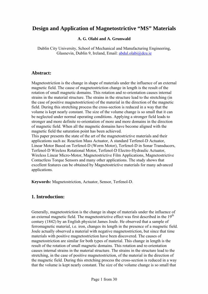
The physical background to the re-orientation of magnetic domains is depicted simplified schematically in Fig. 2. In the region between 0 and 1, where the applied magnetic field is small, the magnetic domains show almost no common orientation pattern. Depending on how the material was formed there may be a small amount of a common orientation pattern, which would show itself as a permanent magnet bias. The resulting strain depends very much on how homogeneous is the base structure of the magnetostrictive material and the material formulation. In the region 1-2 ideally there should be an almost linear relationship between strain and magnetic field. Because the relationship is a simple one, it is easier to predict the behaviour of the material and so most devices are designed to operate in this region. Beyond point 2, the relationship becomes non-linear again as a result of the fact that most of the magnetic domains have become aligned with the magnetic field direction. At point 3 there is a saturation effect, which prevents further strain increase.
Page 3 from 30
Fig. 2, Strain versus magnetic field, schematically
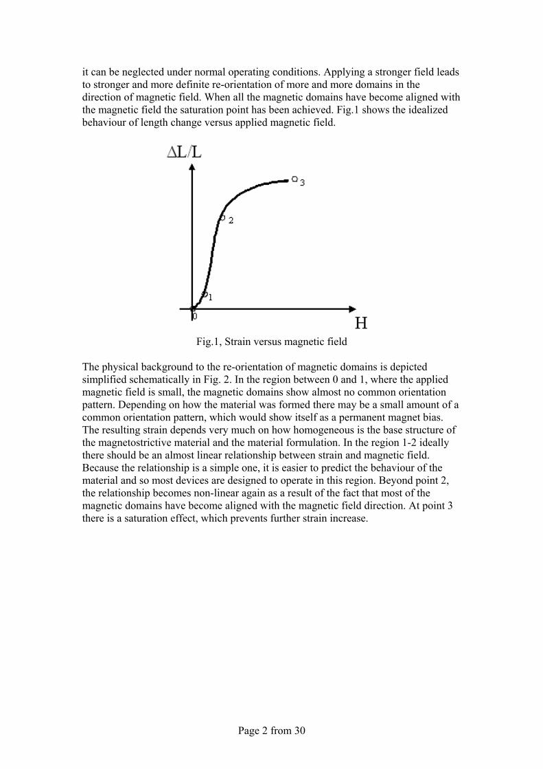
Other effects due to pre-stress and magnetic bias will be explained in the section on optimization. The behaviour of the magnetostrictive materials in various applications is complex, because the changing conditions during operation cause changes in material properties. A full understanding of the complexity will enable engineers to use the potential advantages of magnetostrictive materials and to optimize an actuator based on “giant” magnetostrictive materials. Fig. 3 shows the idealized behaviour of length change in response to applied magnetic field. When a magnetic field is established in the opposite direction, the field is understood to be negative, but the negative field produces the same elongation in the magnetostrictive material, as a positive field would. The shape of the curve is reminiscent of a butterfly and so the curves are referred as butterfly curves.
Fig. 3, Strain versus symmetric magnetic field
Page 4 from 30
2. Magnetostriction Effects
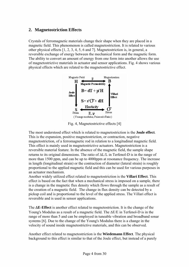
Crystals of ferromagnetic materials change their shape when they are placed in a magnetic field. This phenomenon is called magnetostriction. It is related to various other physical effects [1, 2, 3, 4, 5, 6 and 7]. Magnetostriction is, in general, a reversible exchange of energy between the mechanical form and the magnetic form. The ability to convert an amount of energy from one form into another allows the use of magnetostrictive materials in actuator and sensor applications. Fig. 4 shows various physical effects which are related to the magnetostrictive effect.
Fig. 4, Magnetostrictive effects [4]
The most understood effect which is related to magnetostriction is the Joule effect. This is the expansion, positive magnetostriction, or contraction, negative magnetostriction, of a ferromagnetic rod in relation to a longitudinal magnetic field. This effect is mainly used in magnetostrictive actuators. Magnetostriction is a reversible material feature. In the absence of the magnetic field, the sample shape returns to its original dimensions. The ratio of ΔL/L in Terfenol-D is in the range of more than 1500 ppm, and can be up to 4000ppm at resonance frequency. The increase in length (longitudinal strain) or the contraction of diameter (lateral strain) is roughly proportional to the applied magnetic field and this can be used for various purposes in an actuator mechanism. Another widely utilized effect related to magnetostriction is the Villari Effect. This effect is based on the fact that when a mechanical stress is imposed on a sample, there is a change in the magnetic flux density which flows through the sample as a result of the creation of a magnetic field. The change in flux density can be detected by a pickup coil and is proportional to the level of the applied stress. The Villari effect is reversible and is used in sensor applications. The ΔE-Effect is another effect related to magnetostriction. It is the change of the Young's Modulus as a result of a magnetic field. The ΔE/E in Terfenol-D is in the range of more than 5 and can be employed in tuneable vibration and broadband sonar systems [6]. Due to the change of the Young's Modulus there is a change in the velocity of sound inside magnetostrictive materials, and this can be observed. Another effect related to magnetostriction is the Wiedemann Effect. The physical background to this effect is similar to that of the Joule effect, but instead of a purely
Page 5 from 30
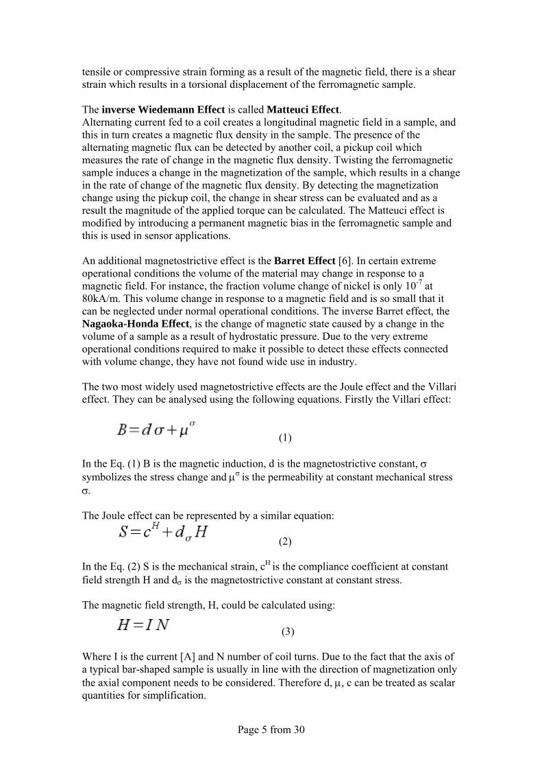
tensile or compressive strain forming as a result of the magnetic field, there is a shear strain which results in a torsional displacement of the ferromagnetic sample. The inverse Wiedemann Effect is called Matteuci Effect. Alternating current fed to a coil creates a longitudinal magnetic field in a sample, and this in turn creates a magnetic flux density in the sample. The presence of the alternating magnetic flux can be detected by another coil, a pickup coil which measures the rate of change in the magnetic flux density. Twisting the ferromagnetic sample induces a change in the magnetization of the sample, which results in a change in the rate of change of the magnetic flux density. By detecting the magnetization change using the pickup coil, the change in shear stress can be evaluated and as a result the magnitude of the applied torque can be calculated. The Matteuci effect is modified by introducing a permanent magnetic bias in the ferromagnetic sample and this is used in sensor applications. An additional magnetostrictive effect is the Barret Effect [6]. In certain extreme operational conditions the volume of the material may change in response to a magnetic field. For instance, the fraction volume change of nickel is only 10-7 at 80kA/m. This volume change in response to a magnetic field and is so small that it can be neglected under normal operational conditions. The inverse Barret effect, the Nagaoka-Honda Effect, is the change of magnetic state caused by a change in the volume of a sample as a result of hydrostatic pressure. Due to the very extreme operational conditions required to make it possible to detect these effects connected with volume change, they have not found wide use in industry. The two most widely used magnetostrictive effects are the Joule effect and the Villari effect. They can be analysed using the following equations. Firstly the Villari effect:
(1) In the Eq. (1) B is the magnetic induction, d is the magnetostrictive constant, σ symbolizes the stress change and μσ is the permeability at constant mechanical stress σ. The Joule effect can be represented by a similar equation:
(2) In the Eq. (2) S is the mechanical strain, cH is the compliance coefficient at constant field strength H and dσ is the magnetostrictive constant at constant stress. The magnetic field strength, H, could be calculated using:
(3) Where I is the current [A] and N number of coil turns. Due to the fact that the axis of a typical bar-shaped sample is usually in line with the direction of magnetization only the axial component needs to be considered. Therefore d, μ, c can be treated as scalar quantities for simplification.
Page 6 from 30
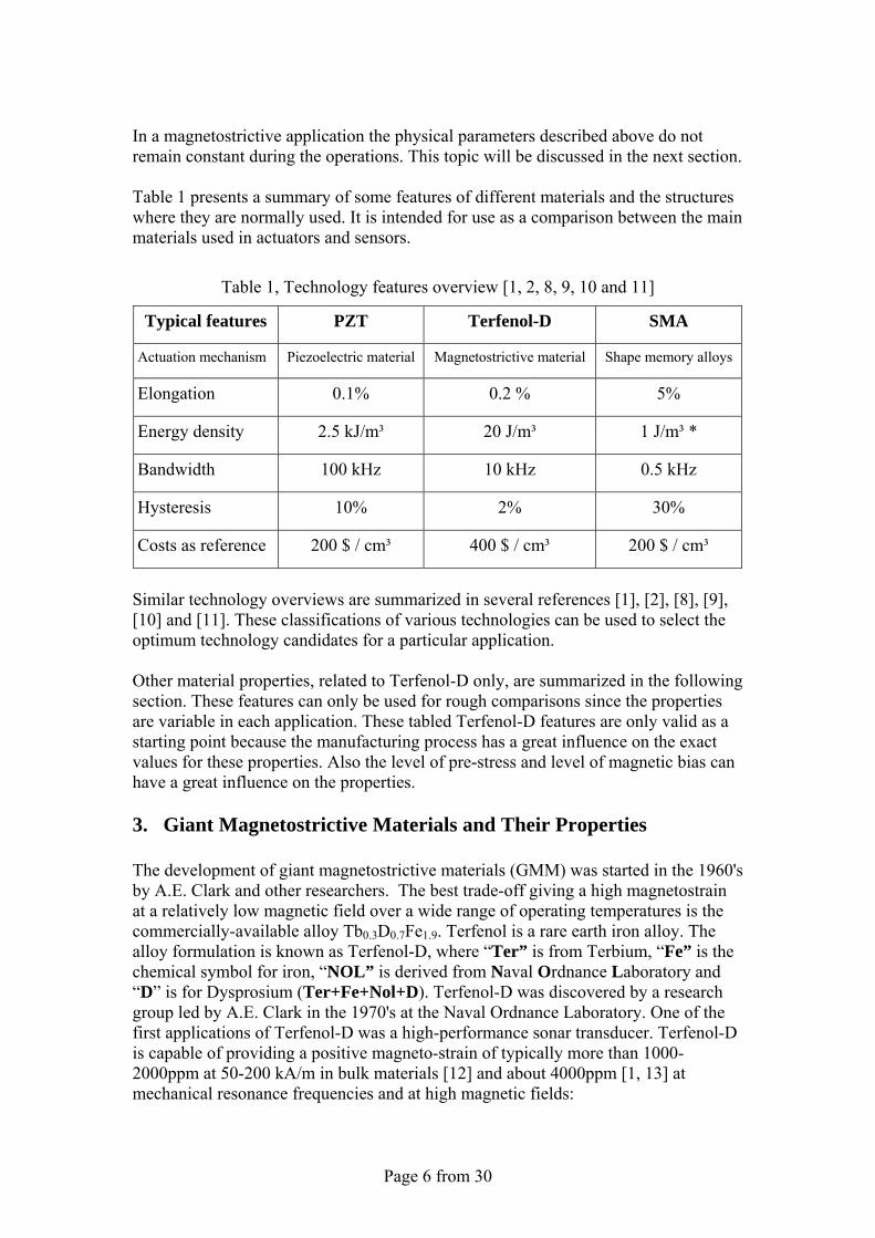
In a magnetostrictive application the physical parameters described above do not remain constant during the operations. This topic will be discussed in the next section. Table 1 presents a summary of some features of different materials and the structures where they are normally used. It is intended for use as a comparison between the main materials used in actuators and sensors.
Table 1, Technology features overview [1, 2, 8, 9, 10 and 11]
Typical features PZT Terfenol-D SMA
Actuation mechanism Piezoelectric material Magnetostrictive material Shape memory alloys
Elongation 0.1% 0.2 % 5%
Energy density 2.5 kJ/m³ 20 J/m³ 1 J/m³ *
Bandwidth 100 kHz 10 kHz 0.5 kHz
Hysteresis 10% 2% 30%
Costs as reference 200 $ / cm³ 400 $ / cm³ 200 $ / cm³
Similar technology overviews are summarized in several references [1], [2], [8], [9], [10] and [11]. These classifications of various technologies can be used to select the optimum technology candidates for a particular application. Other material properties, related to Terfenol-D only, are summarized in the following section. These features can only be used for rough comparisons since the properties are variable in each application. These tabled Terfenol-D features are only valid as a starting point because the manufacturing process has a great influence on the exact values for these properties. Also the level of pre-stress and level of magnetic bias can have a great influence on the properties. 3. Giant Magnetostrictive Materials and Their Properties The development of giant magnetostrictive materials (GMM) was started in the 1960's by A.E. Clark and other researchers. The best trade-off giving a high magnetostrain at a relatively low magnetic field over a wide range of operating temperatures is the commercially-available alloy Tb0.3D0.7Fe1.9. Terfenol is a rare earth iron alloy. The alloy formulation is known as Terfenol-D, where “Ter” is from Terbium, “Fe” is the chemical symbol for iron, “NOL” is derived from Naval Ordnance Laboratory and “D” is for Dysprosium (Ter+Fe+Nol+D). Terfenol-D was discovered by a research group led by A.E. Clark in the 1970's at the Naval Ordnance Laboratory. One of the first applications of Terfenol-D was a high-performance sonar transducer. Terfenol-D is capable of providing a positive magneto-strain of typically more than 1000-2000ppm at 50-200 kA/m in bulk materials [12] and about 4000ppm [1, 13] at mechanical resonance frequencies and at high magnetic fields:
Page 7 from 30
(4)
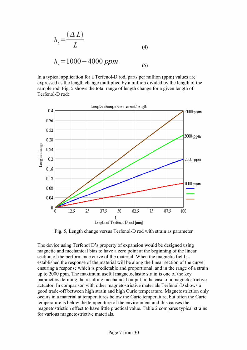
(5) In a typical application for a Terfenol-D rod, parts per million (ppm) values are expressed as the length change multiplied by a million divided by the length of the sample rod. Fig. 5 shows the total range of length change for a given length of Terfenol-D rod:
Fig. 5, Length change versus Terfenol-D rod with strain as parameter
The device using Terfenol D’s property of expansion would be designed using magnetic and mechanical bias to have a zero point at the beginning of the linear section of the performance curve of the material. When the magnetic field is established the response of the material will be along the linear section of the curve, ensuring a response which is predictable and proportional, and in the range of a strain up to 2000 ppm. The maximum useful magnetoelastic strain is one of the key parameters defining the resulting mechanical output in the case of a magnetostrictive actuator. In comparison with other magnetostrictive materials Terfenol-D shows a good trade-off between high strain and high Curie temperature. Magnetostriction only occurs in a material at temperatures below the Curie temperature, but often the Curie temperature is below the temperature of the environment and this causes the magnetostriction effect to have little practical value. Table 2 compares typical strains for various magnetostrictive materials.
Page 8 from 30
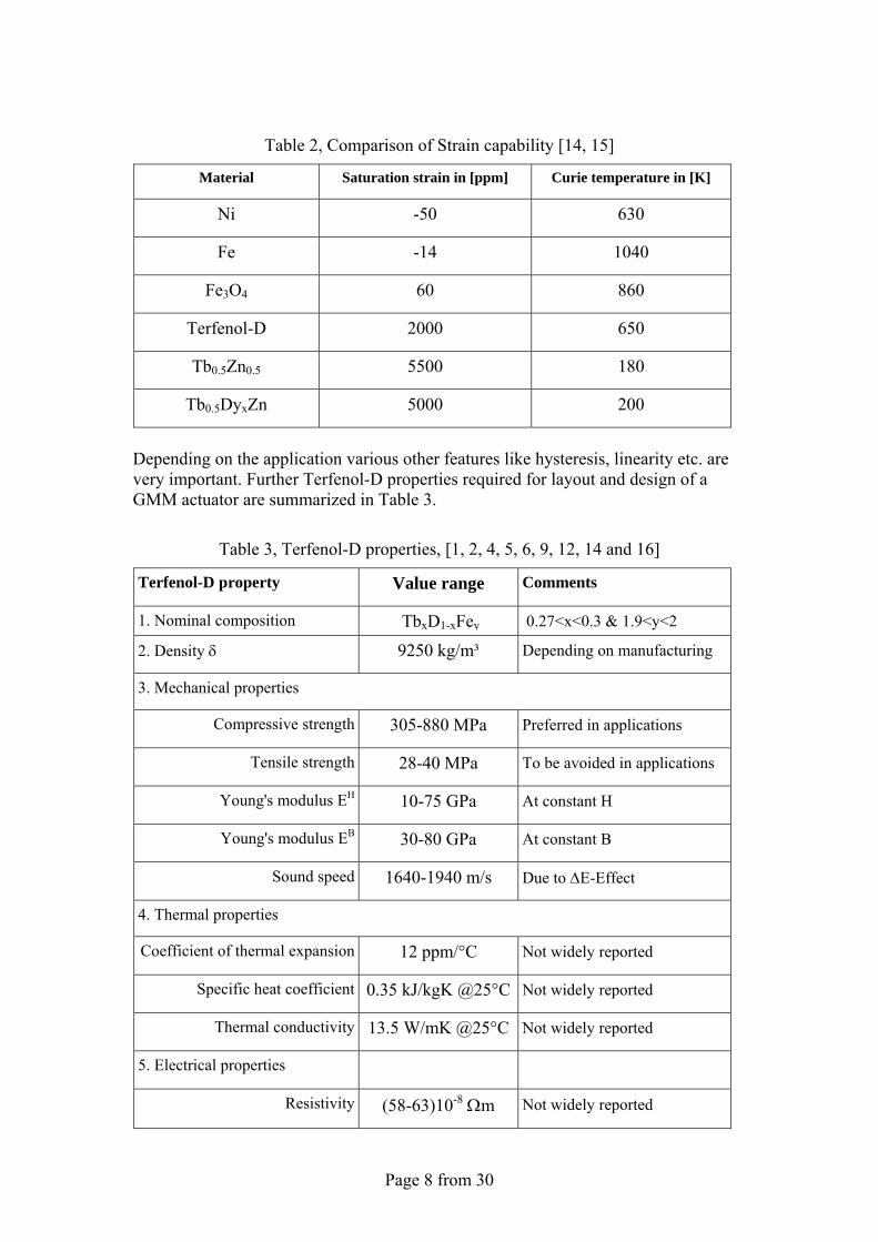
Table 2, Comparison of Strain capability [14, 15]
Material Saturation strain in [ppm] Curie temperature in [K]
Ni -50 630
Fe -14 1040
Fe3O4 60 860
Terfenol-D 2000 650
Tb0.5Zn0.5 5500 180
Tb0.5DyxZn 5000 200
Depending on the application various other features like hysteresis, linearity etc. are very important. Further Terfenol-D properties required for layout and design of a GMM actuator are summarized in Table 3.
Table 3, Terfenol-D properties, [1, 2, 4, 5, 6, 9, 12, 14 and 16]
Terfenol-D property Value range Comments
1. Nominal composition TbxD1-xFey 0.27<x<0.3 & 1.9<y<2
2. Density δ 9250 kg/m³ Depending on manufacturing
3. Mechanical properties
Compressive strength 305-880 MPa Preferred in applications
Tensile strength 28-40 MPa To be avoided in applications
Young's modulus EH 10-75 GPa At constant H
Young's modulus EB 30-80 GPa At constant B
Sound speed 1640-1940 m/s Due to ΔE-Effect
4. Thermal properties
Coefficient of thermal expansion 12 ppm/°C Not widely reported
Specific heat coefficient 0.35 kJ/kgK @25°C Not widely reported
Thermal conductivity 13.5 W/mK @25°C Not widely reported
5. Electrical properties
Resistivity (58-63)10-8 Ωm Not widely reported
Page 9 from 30
Terfenol-D property Value range Comments
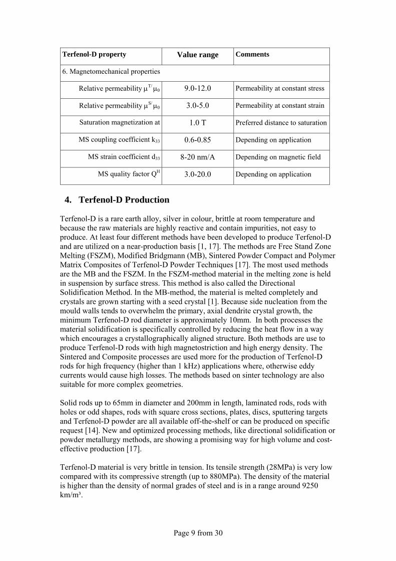
6. Magnetomechanical properties
Relative permeability μT/ μ0 9.0-12.0 Permeability at constant stress
Relative permeability μS/ μ0 3.0-5.0 Permeability at constant strain
Saturation magnetization at 1.0 T Preferred distance to saturation
MS coupling coefficient k33 0.6-0.85 Depending on application
MS strain coefficient d33 8-20 nm/A Depending on magnetic field
MS quality factor QH 3.0-20.0 Depending on application
4. Terfenol-D Production
Terfenol-D is a rare earth alloy, silver in colour, brittle at room temperature and because the raw materials are highly reactive and contain impurities, not easy to produce. At least four different methods have been developed to produce Terfenol-D and are utilized on a near-production basis [1, 17]. The methods are Free Stand Zone Melting (FSZM), Modified Bridgmann (MB), Sintered Powder Compact and Polymer Matrix Composites of Terfenol-D Powder Techniques [17]. The most used methods are the MB and the FSZM. In the FSZM-method material in the melting zone is held in suspension by surface stress. This method is also called the Directional Solidification Method. In the MB-method, the material is melted completely and crystals are grown starting with a seed crystal [1]. Because side nucleation from the mould walls tends to overwhelm the primary, axial dendrite crystal growth, the minimum Terfenol-D rod diameter is approximately 10mm. In both processes the material solidification is specifically controlled by reducing the heat flow in a way which encourages a crystallographically aligned structure. Both methods are use to produce Terfenol-D rods with high magnetostriction and high energy density. The Sintered and Composite processes are used more for the production of Terfenol-D rods for high frequency (higher than 1 kHz) applications where, otherwise eddy currents would cause high losses. The methods based on sinter technology are also suitable for more complex geometries. Solid rods up to 65mm in diameter and 200mm in length, laminated rods, rods with holes or odd shapes, rods with square cross sections, plates, discs, sputtering targets and Terfenol-D powder are all available off-the-shelf or can be produced on specific request [14]. New and optimized processing methods, like directional solidification or powder metallurgy methods, are showing a promising way for high volume and cost-effective production [17]. Terfenol-D material is very brittle in tension. Its tensile strength (28MPa) is very low compared with its compressive strength (up to 880MPa). The density of the material is higher than the density of normal grades of steel and is in a range around 9250 km/m³.
Page 10 from 30
4.1 Young's Modulus
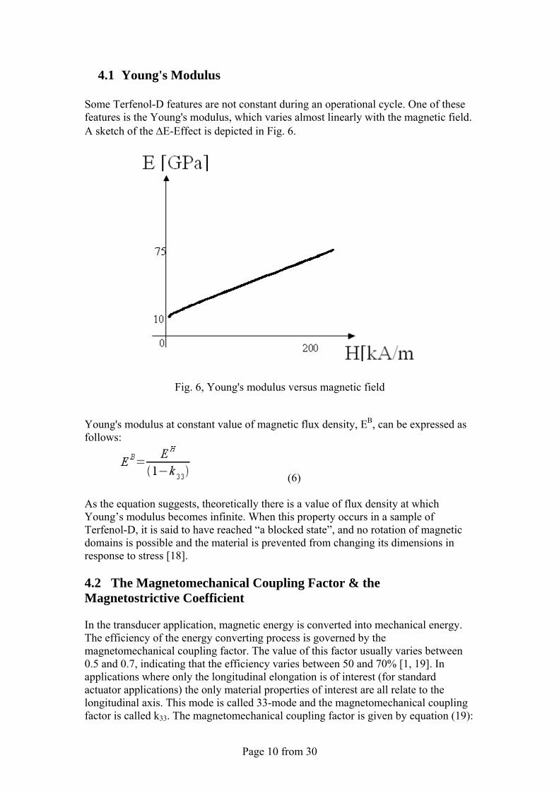
Some Terfenol-D features are not constant during an operational cycle. One of these features is the Young's modulus, which varies almost linearly with the magnetic field. A sketch of the ΔE-Effect is depicted in Fig. 6.
Fig. 6, Young's modulus versus magnetic field
Young's modulus at constant value of magnetic flux density, EB, can be expressed as follows:
(6) As the equation suggests, theoretically there is a value of flux density at which Young’s modulus becomes infinite. When this property occurs in a sample of Terfenol-D, it is said to have reached “a blocked state”, and no rotation of magnetic domains is possible and the material is prevented from changing its dimensions in response to stress [18]. 4.2 The Magnetomechanical Coupling Factor & the Magnetostrictive Coefficient In the transducer application, magnetic energy is converted into mechanical energy. The efficiency of the energy converting process is governed by the magnetomechanical coupling factor. The value of this factor usually varies between 0.5 and 0.7, indicating that the efficiency varies between 50 and 70% [1, 19]. In applications where only the longitudinal elongation is of interest (for standard actuator applications) the only material properties of interest are all relate to the longitudinal axis. This mode is called 33-mode and the magnetomechanical coupling factor is called k33. The magnetomechanical coupling factor is given by equation (19):
Page 11 from 30
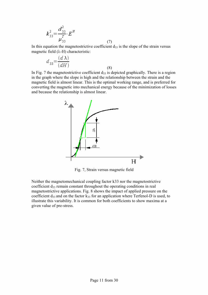
(7) In this equation the magnetostrictive coefficient d33 is the slope of the strain versus magnetic field (λ-H) characteristic:
(8) In Fig. 7 the magnetostrictive coefficient d33 is depicted graphically. There is a region in the graph where the slope is high and the relationship between the strain and the magnetic field is almost linear. This is the optimal working range, and is preferred for converting the magnetic into mechanical energy because of the minimization of losses and because the relationship is almost linear.
Fig. 7, Strain versus magnetic field
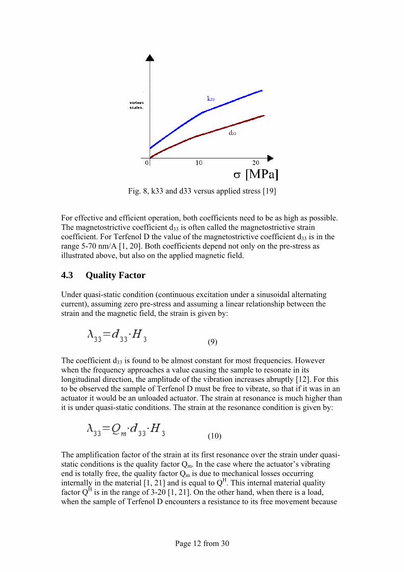
Neither the magnetomechanical coupling factor k33 nor the magnetostrictive coefficient d33 remain constant throughout the operating conditions in real magnetostrictive applications. Fig. 8 shows the impact of applied pressure on the coefficient d33 and on the factor k33 for an application where Terfenol-D is used, to illustrate this variability. It is common for both coefficients to show maxima at a given value of pre-stress.
Page 12 from 30
Fig. 8, k33 and d33 versus applied stress [19]
For effective and efficient operation, both coefficients need to be as high as possible. The magnetostrictive coefficient d33 is often called the magnetostrictive strain coefficient. For Terfenol D the value of the magnetostrictive coefficient d33 is in the range 5-70 nm/A [1, 20]. Both coefficients depend not only on the pre-stress as illustrated above, but also on the applied magnetic field. 4.3 Quality Factor Under quasi-static condition (continuous excitation under a sinusoidal alternating current), assuming zero pre-stress and assuming a linear relationship between the strain and the magnetic field, the strain is given by:
(9)
The coefficient d33 is found to be almost constant for most frequencies. However when the frequency approaches a value causing the sample to resonate in its longitudinal direction, the amplitude of the vibration increases abruptly [12]. For this to be observed the sample of Terfenol D must be free to vibrate, so that if it was in an actuator it would be an unloaded actuator. The strain at resonance is much higher than it is under quasi-static conditions. The strain at the resonance condition is given by:
(10) The amplification factor of the strain at its first resonance over the strain under quasi-static conditions is the quality factor Qm. In the case where the actuator’s vibrating end is totally free, the quality factor Qm is due to mechanical losses occurring internally in the material [1, 21] and is equal to QH. This internal material quality factor QH is in the range of 3-20 [1, 21]. On the other hand, when there is a load, when the sample of Terfenol D encounters a resistance to its free movement because
Page 13 from 30
of the surrounding assembly, a damping feature is introduced into the vibration and the quality factor QH is reduced to a value Qm. 4.4 Permeability The constant μ0=2π10-7 Tm/A defines the magnetic permeability of free space. The permeabilities of most materials are close to the permeability of the free space. These materials are called paramagnetic or diamagnetic. In the case of ferromagnetic materials the permeability is very large and it is common to express the permeability in terms of a new property, the relative permeability. This is the number of times the permeability of free space must be multiplied by in order to arrive at a value for the permeability of the material. Since this is a number values of relative permeability are dimensionless. The relative permeability therefore indicates the amplification of magnetic effects in a magnetic material, which is expressed as the amplitude of the magnetic flux density in a magnetic material in response to a given magnetic field. The relative permeability of Terfenol-D is much smaller than of a magnetic iron. Table 4 presents a range of relative permeabilities including Terfenol-D.
Table 4, Relative permeability [22]
Relative permeability Value range
Mu-metal 20000
Permalloy 8000
Magnetic iron 200
Nickel 100
Terfenol-D <10
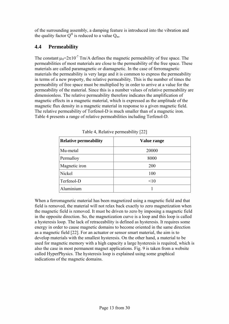
Aluminium 1 When a ferromagnetic material has been magnetized using a magnetic field and that field is removed, the material will not relax back exactly to zero magnetization when the magnetic field is removed. It must be driven to zero by imposing a magnetic field in the opposite direction. So, the magnetization curve is a loop and this loop is called a hysteresis loop. The lack of retraceability is defined as hysteresis. It requires some energy in order to cause magnetic domains to become oriented in the same direction as a magnetic field [22]. For an actuator or sensor smart material, the aim is to develop materials with the smallest hysteresis. On the other hand, a material to be used for magnetic memory with a high capacity a large hysteresis is required, which is also the case in most permanent magnet applications. Fig. 9 is taken from a website called HyperPhysics. The hysteresis loop is explained using some graphical indications of the magnetic domains.
Page 14 from 30
Fig. 9, Magnetization curve [22]
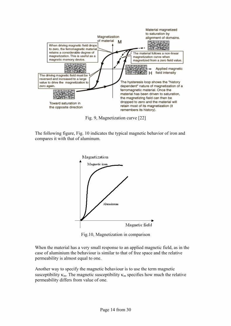
The following figure, Fig. 10 indicates the typical magnetic behavior of iron and compares it with that of aluminum.
Fig.10, Magnetization in comparison
When the material has a very small response to an applied magnetic field, as in the case of aluminium the behaviour is similar to that of free space and the relative permeability is almost equal to one. Another way to specify the magnetic behaviour is to use the term magnetic susceptibility κm. The magnetic susceptibility κm specifies how much the relative permeability differs from value of one.
Page 15 from 30
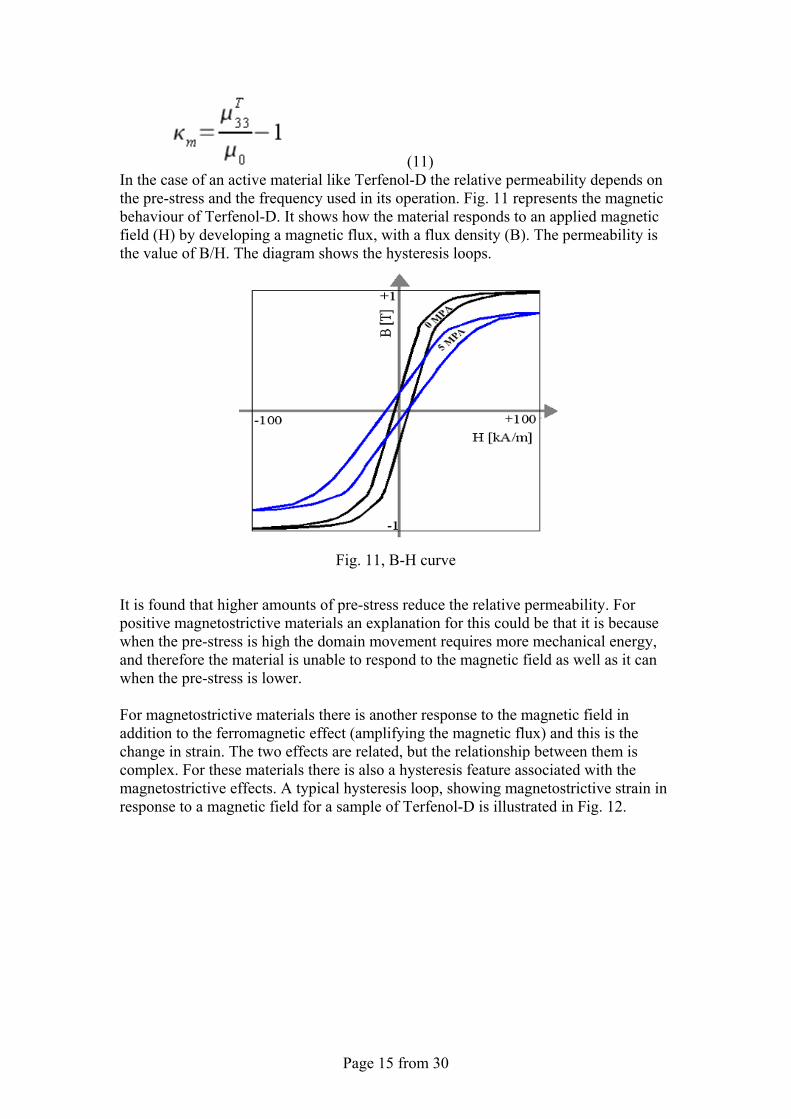
(11) In the case of an active material like Terfenol-D the relative permeability depends on the pre-stress and the frequency used in its operation. Fig. 11 represents the magnetic behaviour of Terfenol-D. It shows how the material responds to an applied magnetic field (H) by developing a magnetic flux, with a flux density (B). The permeability is the value of B/H. The diagram shows the hysteresis loops.
Fig. 11, B-H curve
It is found that higher amounts of pre-stress reduce the relative permeability. For positive magnetostrictive materials an explanation for this could be that it is because when the pre-stress is high the domain movement requires more mechanical energy, and therefore the material is unable to respond to the magnetic field as well as it can when the pre-stress is lower. For magnetostrictive materials there is another response to the magnetic field in addition to the ferromagnetic effect (amplifying the magnetic flux) and this is the change in strain. The two effects are related, but the relationship between them is complex. For these materials there is also a hysteresis feature associated with the magnetostrictive effects. A typical hysteresis loop, showing magnetostrictive strain in response to a magnetic field for a sample of Terfenol-D is illustrated in Fig. 12.
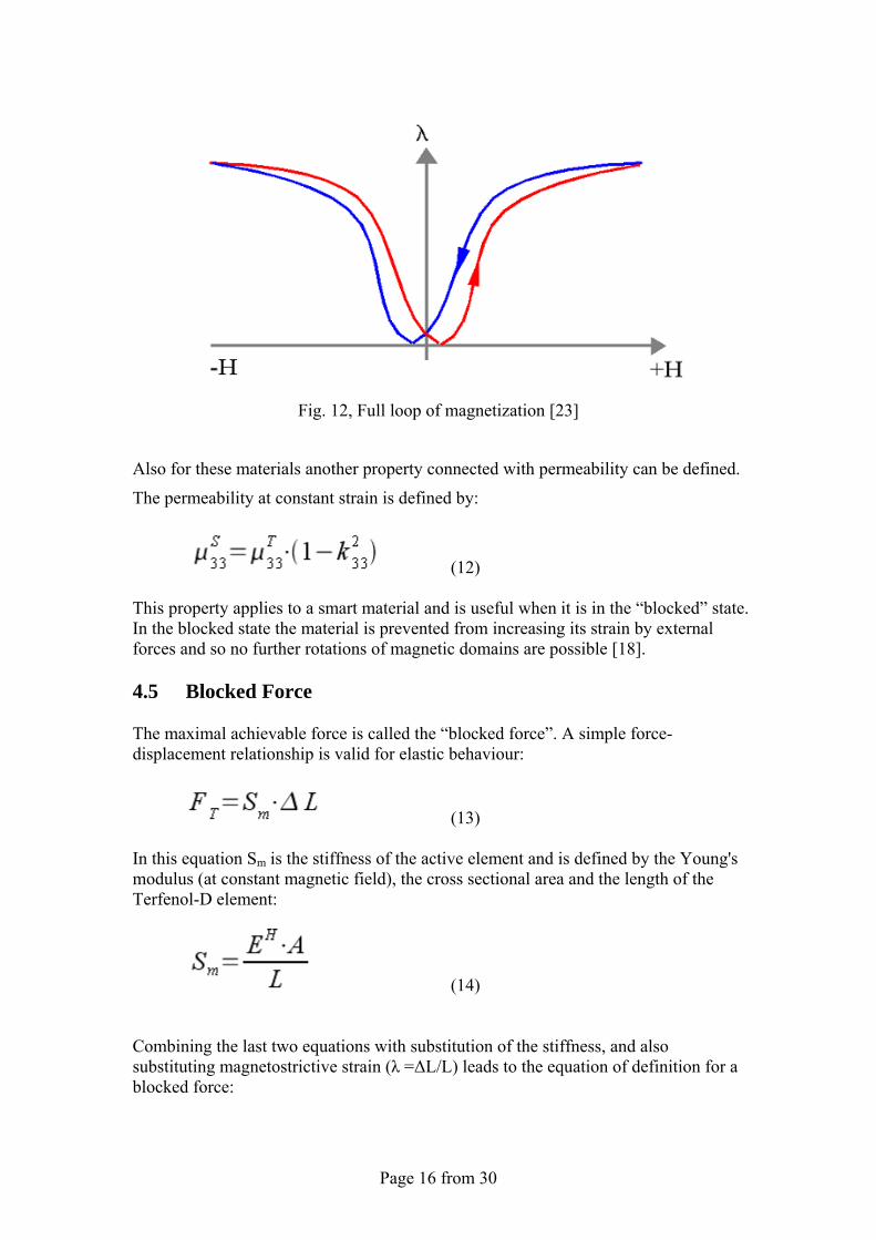
Page 16 from 30
Fig. 12, Full loop of magnetization [23]
Also for these materials another property connected with permeability can be defined.
The permeability at constant strain is defined by:
(12)
This property applies to a smart material and is useful when it is in the “blocked” state. In the blocked state the material is prevented from increasing its strain by external forces and so no further rotations of magnetic domains are possible [18]. 4.5 Blocked Force The maximal achievable force is called the “blocked force”. A simple force-displacement relationship is valid for elastic behaviour:
(13) In this equation Sm is the stiffness of the active element and is defined by the Young's modulus (at constant magnetic field), the cross sectional area and the length of the Terfenol-D element:
(14) Combining the last two equations with substitution of the stiffness, and also substituting magnetostrictive strain (λ =ΔL/L) leads to the equation of definition for a blocked force:
Page 17 from 30
(15)
There is a blocked force which refers to the maximum amount of magnetostrictive strain that can be applied to a sample of Terfenol D. This occurs at very high magnetic filed strengths (at λmax). According to this relationship the blocked force FH
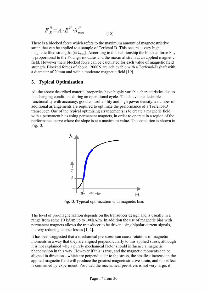
B is proportional to the Young's modulus and the maximal strain at an applied magnetic field. However there blocked force can be calculated for each value of magnetic field strength. Blocked forces of about 12000N are achievable with a Terfenol-D shaft with a diameter of 20mm and with a moderate magnetic field [19]. 5. Typical Optimization All the above described material properties have highly variable characteristics due to the changing conditions during an operational cycle. To achieve the desirable functionality with accuracy, good controllability and high power density, a number of additional arrangements are required to optimize the performance of a Terfenol-D transducer. One of the typical optimising arrangements is to create a magnetic field with a permanent bias using permanent magnets, in order to operate in a region of the performance curve where the slope is at a maximum value. This condition is shown in Fig.13.
Fig.13, Typical optimization with magnetic bias
The level of pre-magnetization depends on the transducer design and is usually in a range from some 10 kA/m up to 100kA/m. In addition the use of magnetic bias with permanent magnets allows the transducer to be driven using bipolar current signals, thereby reducing copper losses [1, 2].
It has been suggested that a mechanical pre-stress can cause rotations of magnetic moments in a way that they are aligned perpendicularly to this applied stress, although it is not explained why a purely mechanical factor should influence a magnetic phenomenon in this way. However if this is true, and the magnetic moments can be aligned in directions, which are perpendicular to the stress, the smallest increase in the applied magnetic field will produce the greatest magnetostrictive strain, and this effect is confirmed by experiment. Provided the mechanical pre-stress is not very large, it
Page 18 from 30
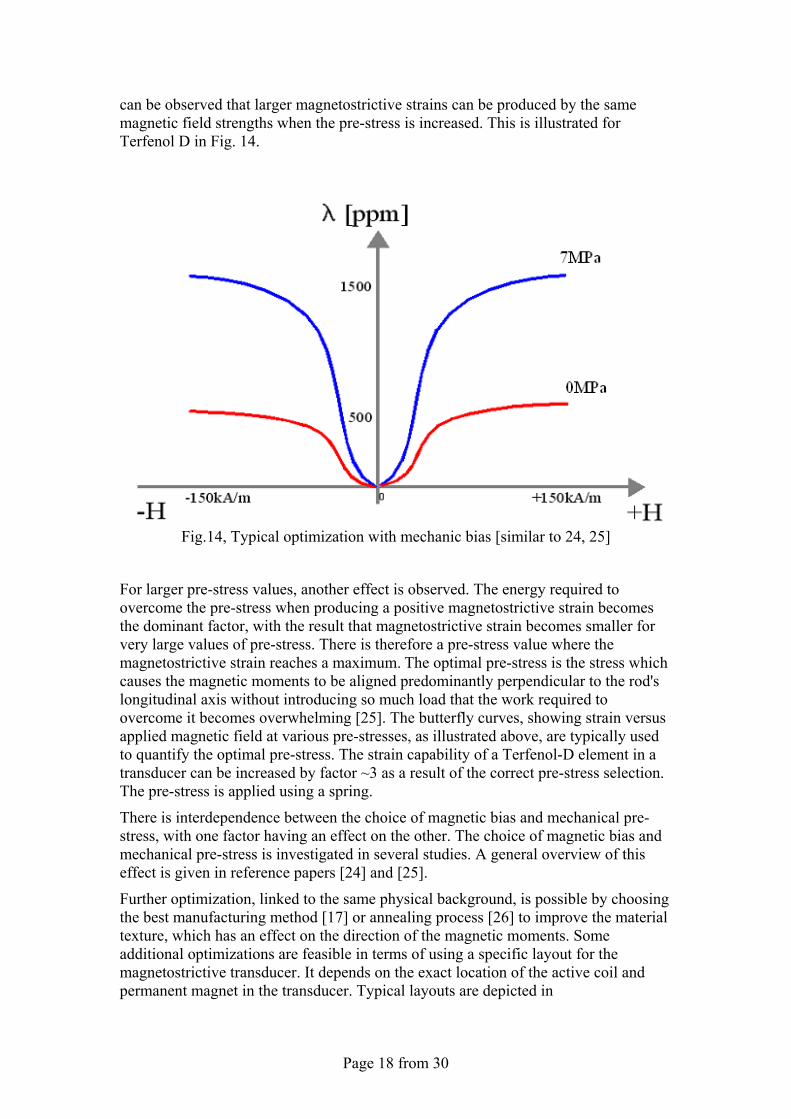
can be observed that larger magnetostrictive strains can be produced by the same magnetic field strengths when the pre-stress is increased. This is illustrated for Terfenol D in Fig. 14.
Fig.14, Typical optimization with mechanic bias [similar to 24, 25]
For larger pre-stress values, another effect is observed. The energy required to overcome the pre-stress when producing a positive magnetostrictive strain becomes the dominant factor, with the result that magnetostrictive strain becomes smaller for very large values of pre-stress. There is therefore a pre-stress value where the magnetostrictive strain reaches a maximum. The optimal pre-stress is the stress which causes the magnetic moments to be aligned predominantly perpendicular to the rod's longitudinal axis without introducing so much load that the work required to overcome it becomes overwhelming [25]. The butterfly curves, showing strain versus applied magnetic field at various pre-stresses, as illustrated above, are typically used to quantify the optimal pre-stress. The strain capability of a Terfenol-D element in a transducer can be increased by factor ~3 as a result of the correct pre-stress selection. The pre-stress is applied using a spring.
There is interdependence between the choice of magnetic bias and mechanical pre-stress, with one factor having an effect on the other. The choice of magnetic bias and mechanical pre-stress is investigated in several studies. A general overview of this effect is given in reference papers [24] and [25].
Further optimization, linked to the same physical background, is possible by choosing the best manufacturing method [17] or annealing process [26] to improve the material texture, which has an effect on the direction of the magnetic moments. Some additional optimizations are feasible in terms of using a specific layout for the magnetostrictive transducer. It depends on the exact location of the active coil and permanent magnet in the transducer. Typical layouts are depicted in
Page 19 from 30
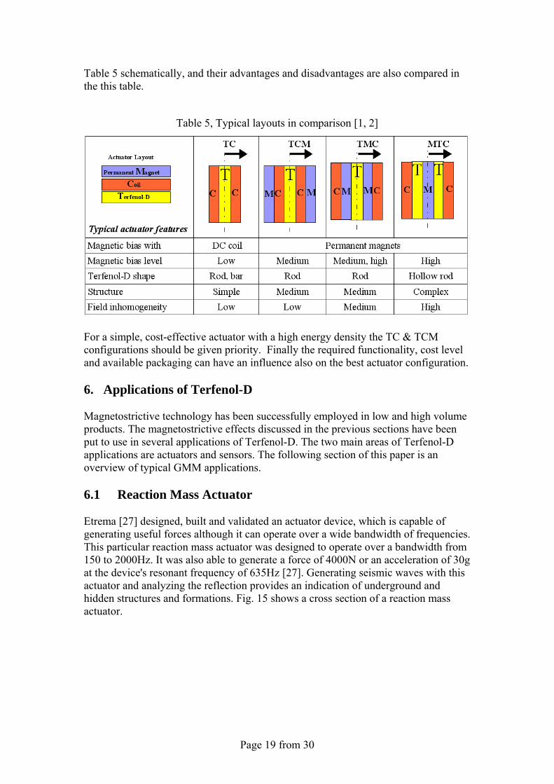
Table 5 schematically, and their advantages and disadvantages are also compared in the this table.
Table 5, Typical layouts in comparison [1, 2]
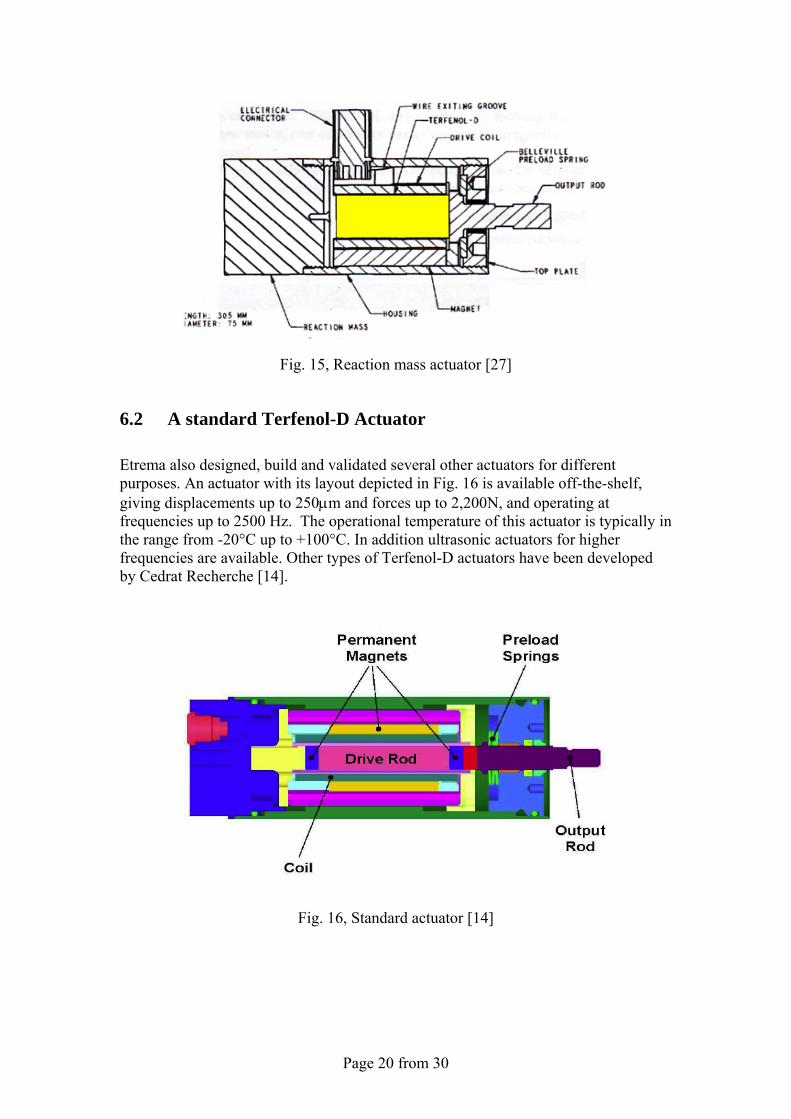
For a simple, cost-effective actuator with a high energy density the TC & TCM configurations should be given priority. Finally the required functionality, cost level and available packaging can have an influence also on the best actuator configuration. 6. Applications of Terfenol-D Magnetostrictive technology has been successfully employed in low and high volume products. The magnetostrictive effects discussed in the previous sections have been put to use in several applications of Terfenol-D. The two main areas of Terfenol-D applications are actuators and sensors. The following section of this paper is an overview of typical GMM applications. 6.1 Reaction Mass Actuator Etrema [27] designed, built and validated an actuator device, which is capable of generating useful forces although it can operate over a wide bandwidth of frequencies. This particular reaction mass actuator was designed to operate over a bandwidth from 150 to 2000Hz. It was also able to generate a force of 4000N or an acceleration of 30g at the device's resonant frequency of 635Hz [27]. Generating seismic waves with this actuator and analyzing the reflection provides an indication of underground and hidden structures and formations. Fig. 15 shows a cross section of a reaction mass actuator.
Page 20 from 30
Fig. 15, Reaction mass actuator [27]
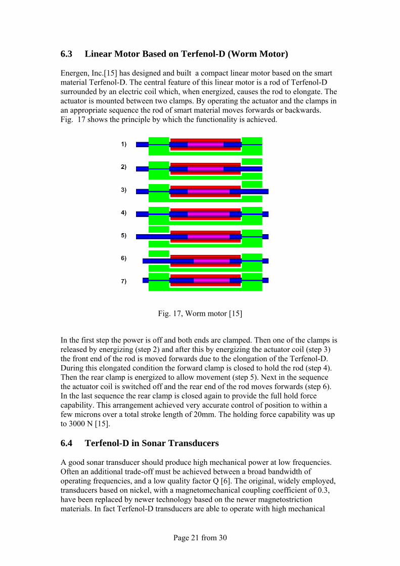
6.2 A standard Terfenol-D Actuator Etrema also designed, build and validated several other actuators for different purposes. An actuator with its layout depicted in Fig. 16 is available off-the-shelf, giving displacements up to 250μm and forces up to 2,200N, and operating at frequencies up to 2500 Hz. The operational temperature of this actuator is typically in the range from -20°C up to +100°C. In addition ultrasonic actuators for higher frequencies are available. Other types of Terfenol-D actuators have been developed by Cedrat Recherche [14].
Fig. 16, Standard actuator [14]
Page 21 from 30
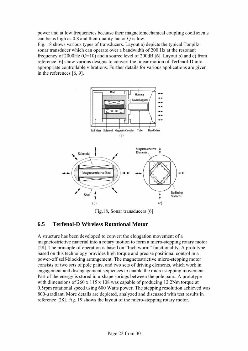
6.3 Linear Motor Based on Terfenol-D (Worm Motor) Energen, Inc.[15] has designed and built a compact linear motor based on the smart material Terfenol-D. The central feature of this linear motor is a rod of Terfenol-D surrounded by an electric coil which, when energized, causes the rod to elongate. The actuator is mounted between two clamps. By operating the actuator and the clamps in an appropriate sequence the rod of smart material moves forwards or backwards. Fig. 17 shows the principle by which the functionality is achieved.
Fig. 17, Worm motor [15]
In the first step the power is off and both ends are clamped. Then one of the clamps is released by energizing (step 2) and after this by energizing the actuator coil (step 3) the front end of the rod is moved forwards due to the elongation of the Terfenol-D. During this elongated condition the forward clamp is closed to hold the rod (step 4). Then the rear clamp is energized to allow movement (step 5). Next in the sequence the actuator coil is switched off and the rear end of the rod moves forwards (step 6). In the last sequence the rear clamp is closed again to provide the full hold force capability. This arrangement achieved very accurate control of position to within a few microns over a total stroke length of 20mm. The holding force capability was up to 3000 N [15]. 6.4 Terfenol-D in Sonar Transducers A good sonar transducer should produce high mechanical power at low frequencies. Often an additional trade-off must be achieved between a broad bandwidth of operating frequencies, and a low quality factor Q [6]. The original, widely employed, transducers based on nickel, with a magnetomechanical coupling coefficient of 0.3, have been replaced by newer technology based on the newer magnetostriction materials. In fact Terfenol-D transducers are able to operate with high mechanical
Page 22 from 30
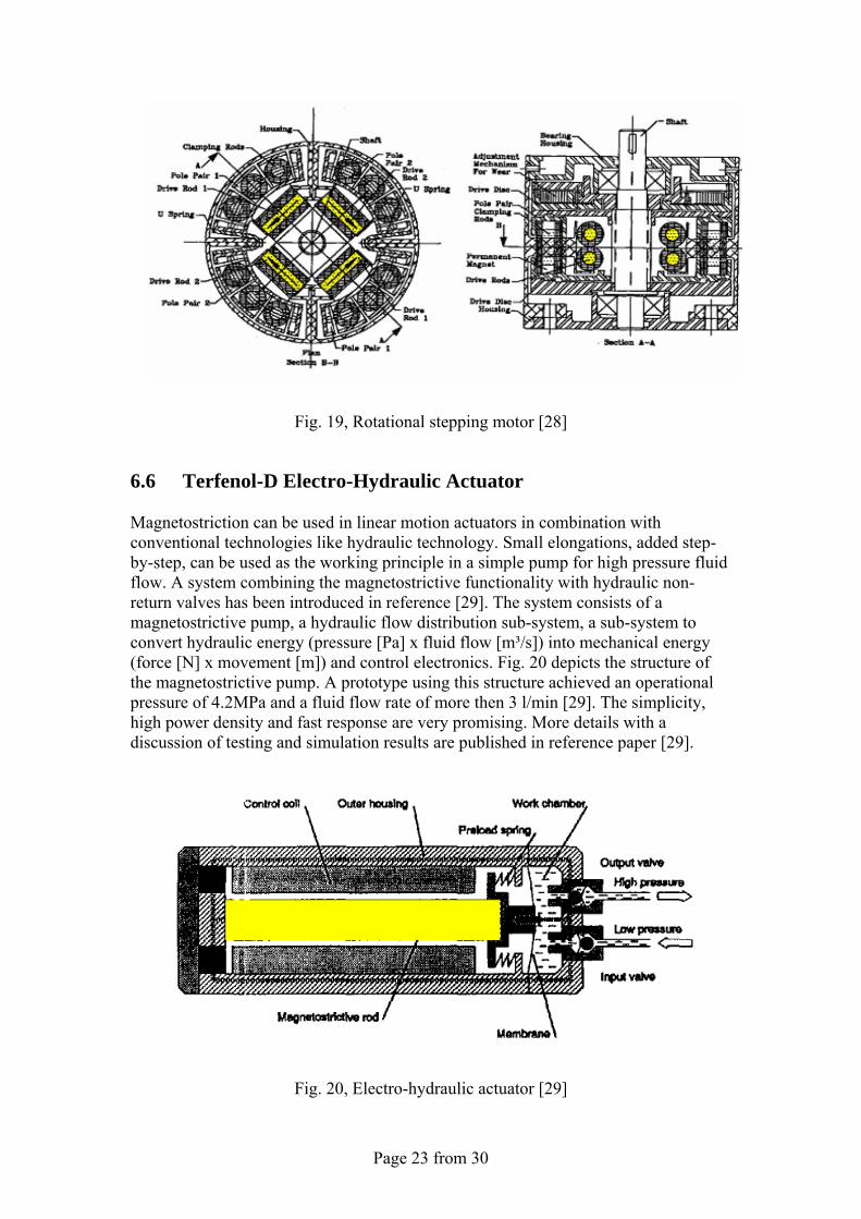
power and at low frequencies because their magnetomechanical coupling coefficients can be as high as 0.8 and their quality factor Q is low. Fig. 18 shows various types of transducers. Layout a) depicts the typical Tonpilz sonar transducer which can operate over a bandwidth of 200 Hz at the resonant frequency of 2000Hz (Q=10) and a source level of 200dB [6]. Layout b) and c) from reference [6] show various designs to convert the linear motion of Terfenol-D into appropriate controllable vibrations. Further details for various applications are given in the references [6, 9].
Fig.18, Sonar transducers [6]
6.5 Terfenol-D Wireless Rotational Motor A structure has been developed to convert the elongation movement of a magnetostrictive material into a rotary motion to form a micro-stepping rotary motor [28]. The principle of operation is based on “Inch worm” functionality. A prototype based on this technology provides high torque and precise positional control in a power-off self-blocking arrangement. The magnetostrictive micro-stepping motor consists of two sets of pole pairs, and two sets of driving elements, which work in engagement and disengagement sequences to enable the micro-stepping movement. Part of the energy is stored in u-shape springs between the pole pairs. A prototype with dimensions of 260 x 115 x 108 was capable of producing 12.2Nm torque at 0.5rpm rotational speed using 600 Watts power. The stepping resolution achieved was 800-μradiant. More details are depicted, analyzed and discussed with test results in reference [28]. Fig. 19 shows the layout of the micro-stepping rotary motor.
Page 23 from 30
Fig. 19, Rotational stepping motor [28]
6.6 Terfenol-D Electro-Hydraulic Actuator Magnetostriction can be used in linear motion actuators in combination with conventional technologies like hydraulic technology. Small elongations, added step-by-step, can be used as the working principle in a simple pump for high pressure fluid flow. A system combining the magnetostrictive functionality with hydraulic non-return valves has been introduced in reference [29]. The system consists of a magnetostrictive pump, a hydraulic flow distribution sub-system, a sub-system to convert hydraulic energy (pressure [Pa] x fluid flow [m³/s]) into mechanical energy (force [N] x movement [m]) and control electronics. Fig. 20 depicts the structure of the magnetostrictive pump. A prototype using this structure achieved an operational pressure of 4.2MPa and a fluid flow rate of more then 3 l/min [29]. The simplicity, high power density and fast response are very promising. More details with a discussion of testing and simulation results are published in reference paper [29].
Fig. 20, Electro-hydraulic actuator [29]
Page 24 from 30
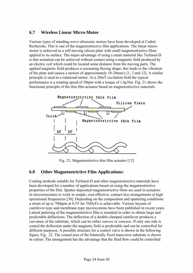
6.7 Wireless Linear Micro-Motor Various types of standing-wave ultrasonic motors have been developed at Cedrat Recherche. This is one of the magnetostrictive film applications. The linear micro-motor is achieved as a self moving silicon plate with small magnetostrictive films applied to its surface. The major advantage of using a smart material like Terfenol-D is that actuation can be achieved without contact using a magnetic field produced by an electric coil which could be located some distance from the moving parts. The applied magnetic field produces a resonating flexing shape; this leads to the vibration of the plate and causes a motion of approximately 10-20mm/s [1, 2 and 12]. A similar principle is used in a rotational motor. At a 20mT excitation field the typical performance is a rotating speed of 30rpm with a torque of 1.6μNm. Fig. 21 shows the functional principle of the thin film actuator based on magnetostrictive materials.
Fig. 21, Magnetostrictive thin film actuator [12]
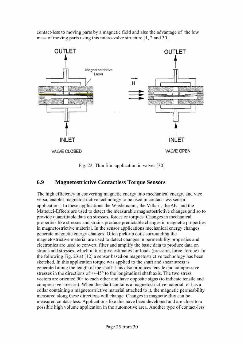
6.8 Other Magnetostrictive Film Applications: Coating methods suitable for Terfenol-D and other magnetostrictive materials have been developed for a number of applications based on using the magnetostrictive properties of the film. Sputter-deposited magnetostrictive films are used in actuators in microstructures to work in simple, cost-effective, contact-less arrangements at high operational frequencies [30]. Depending on the composition and sputtering conditions a strain of up to 700ppm at 0.5T for TbDyFe is achievable. Various layouts of cantilever-type and membrane-type microsystems have been published in recent years. Lateral pattering of the magnetostrictive film is essential in order to obtain large and predictable deflections. The deflection of a double-clamped cantilever produces a curvature of the substrate, which can be either convex or concave. If only one side is coated the deflection under the magnetic field is predictable and can be controlled for different purposes. A possible structure for a control valve is shown in the following figure, Fig. 22. The coated area of the bilaterally fixed transverse substrate is shown in colour. The arrangement has the advantage that the fluid flow could be controlled
Page 25 from 30
contact-less to moving parts by a magnetic field and also the advantage of the low mass of moving parts using this micro-valve structure [1, 2 and 30].
Fig. 22, Thin film application in valves [30]
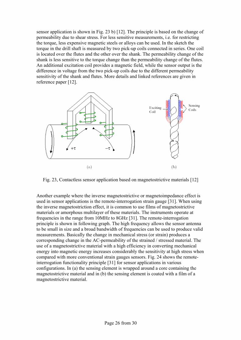
6.9 Magnetostrictive Contactless Torque Sensors The high efficiency in converting magnetic energy into mechanical energy, and vice versa, enables magnetostrictive technology to be used in contact-less sensor applications. In these applications the Wiedemann-, the Villari-, the ΔE- and the Matteuci-Effects are used to detect the measurable magnetostrictive changes and so to provide quantifiable data on stresses, forces or torques. Changes in mechanical properties like stresses and strains produce predictable changes in magnetic properties in magnetostrictive material. In the sensor applications mechanical energy changes generate magnetic energy changes. Often pick-up coils surrounding the magnetostrictive material are used to detect changes in permeability properties and electronics are used to convert, filter and amplify the basic data to produce data on strains and stresses, which in turn give estimates for loads (pressure, force, torque). In the following Fig. 23 a) [12] a sensor based on magnetostrictive technology has been sketched. In this application torque was applied to the shaft and shear stress is generated along the length of the shaft. This also produces tensile and compressive stresses in the directions of +/-45° to the longitudinal shaft axis. The two stress vectors are oriented 90° to each other and have opposite signs (to indicate tensile and compressive stresses). When the shaft contains a magnetostrictive material, or has a collar containing a magnetostrictive material attached to it, the magnetic permeability measured along these directions will change. Changes in magnetic flux can be measured contact-less. Applications like this have been developed and are close to a possible high volume application in the automotive area. Another type of contact-less
Page 26 from 30
sensor application is shown in Fig. 23 b) [12]. The principle is based on the change of permeability due to shear stress. For less sensitive measurements, i.e. for restricting the torque, less expensive magnetic steels or alloys can be used. In the sketch the torque in the drill shaft is measured by two pick-up coils connected in series. One coil is located over the flutes and the other over the shank. The permeability change of the shank is less sensitive to the torque change than the permeability change of the flutes. An additional excitation coil provides a magnetic field, while the sensor output is the difference in voltage from the two pick-up coils due to the different permeability sensitivity of the shank and flutes. More details and linked references are given in reference paper [12].
Fig. 23, Contactless sensor application based on magnetostrictive materials [12]
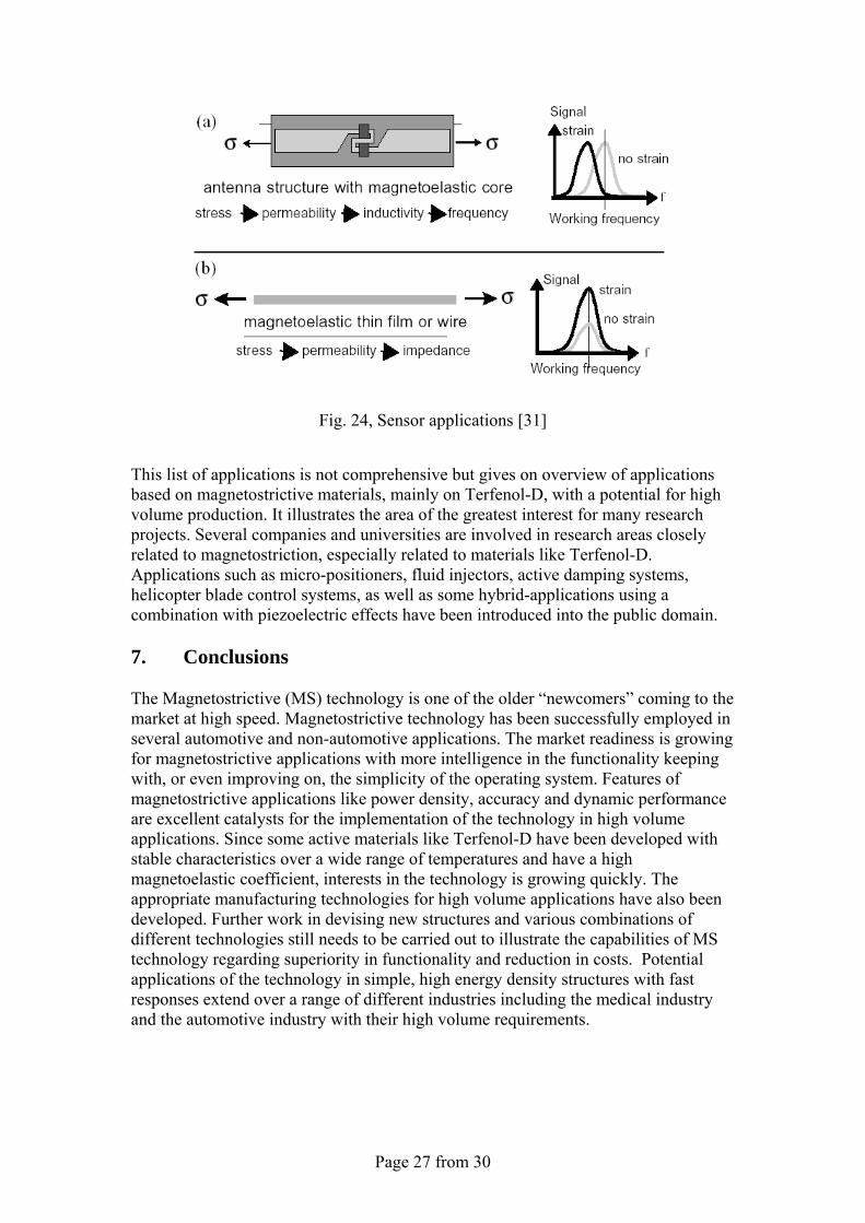
Another example where the inverse magnetostrictive or magnetoimpedance effect is used in sensor applications is the remote-interrogation strain gauge [31]. When using the inverse magnetostriction effect, it is common to use films of magnetostrictive materials or amorphous multilayer of these materials. The instruments operate at frequencies in the range from 10MHz to 8GHz [31]. The remote-interrogation principle is shown in following graph. The high frequency allows the sensor antenna to be small in size and a broad bandwidth of frequencies can be used to produce valid measurements. Basically the change in mechanical stress (or strain) produces a corresponding change in the AC-permeability of the strained / stressed material. The use of a magnetostrictive material with a high efficiency in converting mechanical energy into magnetic energy increases considerably the sensitivity at high stress when compared with more conventional strain gauges sensors. Fig. 24 shows the remote-interrogation functionality principle [31] for sensor applications in various configurations. In (a) the sensing element is wrapped around a core containing the magnetostrictive material and in (b) the sensing element is coated with a film of a magnetostrictive material.
Page 27 from 30
Fig. 24, Sensor applications [31]
This list of applications is not comprehensive but gives on overview of applications based on magnetostrictive materials, mainly on Terfenol-D, with a potential for high volume production. It illustrates the area of the greatest interest for many research projects. Several companies and universities are involved in research areas closely related to magnetostriction, especially related to materials like Terfenol-D. Applications such as micro-positioners, fluid injectors, active damping systems, helicopter blade control systems, as well as some hybrid-applications using a combination with piezoelectric effects have been introduced into the public domain. 7. Conclusions The Magnetostrictive (MS) technology is one of the older “newcomers” coming to the market at high speed. Magnetostrictive technology has been successfully employed in several automotive and non-automotive applications. The market readiness is growing for magnetostrictive applications with more intelligence in the functionality keeping with, or even improving on, the simplicity of the operating system. Features of magnetostrictive applications like power density, accuracy and dynamic performance are excellent catalysts for the implementation of the technology in high volume applications. Since some active materials like Terfenol-D have been developed with stable characteristics over a wide range of temperatures and have a high magnetoelastic coefficient, interests in the technology is growing quickly. The appropriate manufacturing technologies for high volume applications have also been developed. Further work in devising new structures and various combinations of different technologies still needs to be carried out to illustrate the capabilities of MS technology regarding superiority in functionality and reduction in costs. Potential applications of the technology in simple, high energy density structures with fast responses extend over a range of different industries including the medical industry and the automotive industry with their high volume requirements.
Page 28 from 30
References: [1] H. Janocha (ed.), F. Claeyssen, Adaptronics and Smart Structures, Springer Verlag, ISBN 3-540-61484-2, Germany 1999, pp. 124-143 [2] H. Janocha (ed.), Actuators, Springer Verlag, ISBN 3-540-61564-4, Germany 2004, pp. 277-292 [3] C. MacWilliam, Design of a Magnetostrictive Actuator, School Of Engineering and Industrial Design, University of Western Sydney, March 2004, Thesis, pp.1-86 [4] Y.Yamamoto, Tokai University Hiratsuka, Japan; H.Eda, J. Shimizu, Department of Systems Engineering, Ibarki University, Hitachi, Japan, Application of Giant Magnetostrictive Materials to Positioning Actuators, 1999 IEEE /ASME International Conference on Advanced Mechatronics, Altanta USA 1999, Conference paper pp. 215-220 [5] Y. Yamamoto, Tokai University Hiratsuka, Japan; T.Makino, Hiro Matsui, Institute of Advanced Technology, Moritex Corporation, Yokohama, Japan; Micro Positioning and Actuation Devices Using Giant Magnetostriction Materials, Conference, 2000 IEEE International Conference on Robotics and Automation, San Francisco CA USA 2000, Conference paper pp. 3635-3640 [6] M.J. Dapino, Department of Mechanical Engineering, The Ohio State University 2091 Robinson Laboratory Columbus, OH 43210-1107, USA, On magnetostrictive materials and their use in smart material transducer, Structural Engineering and Mechanics Journal, USA 2002, pp. 1-28 [7] A.B. Flatau, M. J. Dapino, Aerospace Engr. & Engr, Mechanics, Iowa State University; F. T. Calkins, Boeing Information Space and Defense Systems, High bandwidth tuneability in smart vibration absorber, 1998 SPIE Smart Structures and Materials Conference, paper #3329-19/3327-42 [8] M. Zupan, M.F. Ashby, N.A. Fleck, Cambridge University Engineering Department, Actuator Classifications and Selection, The development of a Database, Advanced Engineering Materials, Weinheim 2002, 4, No. 12, pp. 933-940 [9] Z. Houquing, L. Jianguo, W. Xiurong, X. Yanhoung, Institute of Acoustics, Academia Sinica, Beijing 100080, China, Z. Hongping, Central Iron and Steel Research Institute, Beijing 100081, China, Application of Terfenol-D in China, Journal of Alloys and Compounds 258, 1997, pp. 49-52 [10] MIDE, Active Materials, www.mide.com [11] Frauenhofer Institute for Machine Tools and Forming Technology IWU, Adaptronic Applications, Integration of smart materials into intelligent components of production systems, www.iwu.frauenhofer.de [12] F. Claeyssen, N. Lhermet, R. Le Letty, Cedrat Recherche, Zirst, F38246 Meylan Cedex, France and P. Bouchiloux, Magsoft Corporation, NY 12180, USA, Actuators, transducers and motors based on giant magnetostrictive materials, Journal of Alloys and Component 258 (1997), pp. 61-73 [13] M.G. Aston, Magnetostrictive Technology Systems Ltd, Unit 17, Newlands House, Newlands Science Park, Inglemire, Hull, HU6 7TQ, UK, R.D. Greenough, A.G.I. Jenner, W.J. Metheringham, K. Prajapati, Department of Applied Physics, The University Of Hull, Cottingham Road, Hull, HU6 7RX, UK, Controlled high power actuation utilizing Terfenol-D, Journal of Alloys and Compounds 258, 1997, pp. 97-100 [14] ETREMA Products Inc., Terfenol-D Magnetostrictive Actuator Information, Specifications, Public domain information, www.terfenoltruth.com, www.eterma.com
Page 29 from 30
[15] C.H. Joshi, Energen Inc. Billericia MA USA, Compact Magnetostrictive Actuators and Linear Motors, Conference Actuator 2000, Bremen, Germany June 2000, Conference paper [16] F. Claeyssen, Cedrat Recherche, France; Ph. Bouchilloux, Magsoft Corporation, USA, Design and construction of a new resonant Magnetostrictive Motor, IEE Transactions of Magnetics, September 1996, Vol. 32, No. 5 [17] J.D. Snodgrass, O.D. McMasters, Eterma Products, Inc. 2500 N. Loop Drive, Ames, Iowa 50010, USA, Optimized Terfenol-D manufacturing processes, Journal of Alloys and Compounds 258, 1997, pp. 24-29 [18] M.J. Dapino, F.T. Calkins, B. Flatau, Aerospace Engr. & Engr, Mechanics, Iowa State University, IA5001; D.L. Hall, Iomega Inc. Roy USA , Measured Terfenol-D material properties under varied applied magnetic field levels, 1996 SPIE's Symposium on Smart Structures and Materials, paper # 2717-66 [19] A.G.I. Jenner, R.J.E. Smith, R.D. Greenough, Department of Physics, University of Hull, Hull HU6 7RX, UK; A.J. Wilkinson, School of Engineering, University of Hull , Actuation and transduction by giant magnetostrictive alloys, Mechatronics 10, Journal 2000, pp. 457-466 [20] W.J. Park, Z.H. Lee, Department of Materials Science and Engineering, Korea Advanced Institute of Science and Technology, 373-1 Kusong-dong, Yusong-gu, Taejon 305-701, South Korea, D.R. Son, Department of Physics, Hannam University, 133 Ojeng-dong, Daedeok-gu, Taejon 306-791, South Korea, Modeling of magnetostriction in grain aligned Terfenol-D and preferred orientation change of Terfenol-D dendrites, Journal of Magnetism and Magnetic Materials 248 (2002), pp. 223-229 [21] F. Claeyssen, D. Colombani, Cedrat Recherche, France; A. Tessereau, B. Ducros, Ets Degreane, France, Giant dynamic magnetostrain in rare earth-iron magnetostrictive materials, IEEE Transaction on Magnetics Vol. 27, No. 6, 11/1991, pp. 5343-5345 [22] Basic calculations and physical background information on www.hyperphysics.phy-astr.gsu.edu [23] D.L. Hall, A.B. Flatau, Aerospace Engr. & Engr, Mechanics, Iowa State University, IA5001, Broadband Performance of a Magnetostrictive Shaker, Journal of Intelligent Material Systems and Structures, August 1994, pp. 1-16 [24] F.T. Calkins, M. J. Dapino, A.B. Flatau, Aerospace Eng. & Eng. Mechanics, Iowa State University, IA50011, Effect of prestress on the dynamic performance of a Terfenol-D transducer, 1997 SPIE's Symposium on Smart Structures and Materials, paper # 3041-23 [25] R. Kellog, A. Flatau, Aerospace Eng. & Eng., Mechanics, Iowa State University, IA50011, Blocked force investigation of a Terfenol-D transducer, 1999 SPIE's Symposium on Smart Structures and Materials, paper # 3668-19 [26] W.J. Park, Z.H. Lee, Department of Materials Science and Engineering, Korea Advanced Institute of Science and Technology, 373-1 Kusong-dong, Yusong-gu, Taejon 305-701, South Korea, J.C. Kim, B.J. Ye, Department of Metallurgical Engineering, Kyungpook National University, Teagu 305-701, South Korea, Marcrosegragation in Bridgman growth of Terfenol-D and effects of annealing, Journal of Crystal Growth 212 (2000), pp. 283-290 [27] B. Jones, ETREMA products, Inc; Ch. Liang, San Diego State University; Magnetostriction: Revealing the Unknown, IEEE AES Systems Magazine, March 1996, Journal paper
Page 30 from 30
[28] J. M. Vranish, D.P. Naik, NASA Coddard Space Flight Center, Greenbelt; J.B. Restorff, J.P. Teter, R43, Naval Surface Warfare Center, Silver Spring; Magnetostrictive direct drive rotary motor development, IEEE Transaction on Magnetics Vol. 27, No. 6, November 1991, pp. 5355-5357 [29] D.A. Bushko and J.H. Goldie, SatCon Technology Corporation, Cambridge, MA, High Performance Magnetostrictive Actuators, IEEE AES Systems Magazine, Nov 1991, Journal pp. 21-25 [30] E. Qandt, K. Seemann, Forschungszentrum Karlsruhe, Institute of Materials Research I, D-76021 Karlsruhe, Germany, Fabrication and Simulation of magnetostrictive thin-film actuators, Sensors and Actuators Journal, A50 (1995), Journal pp. 105-109 [31] A. Ludwig, M. Tewes, S. Glasmachers, M. Löhndorf, E. Quandt, Centre of Advanced European Studies and Research (Caesar), Friedensplatz 16, D-5311 Bonn, Germany, High-frequency magnetoelastic materials for remote-interrogated stress sensors, Journal of Magnetism and Magnetic Materials 242-245, 2002, pp. 1126-1131