Embed Size (px)
Citation preview

W * ~ . 8.
29th International Cosmic Ray Conference Pune (2005)
Design and Characteristics of the Anticoincidence Detector for the GLAST Large Area Telescope
A. A. Moiseeva3b, R. C. Hartmanb, T. E. Johnsonb, J. F. Onnesc, and D. J. Thompsonb (a) University Space Research Association, 10211 Wincopin Circle, Columbia, MD 21044, USA (b) NASA/Goddard Space Flight Center, Code 661, Greenbelt, IUD 20771, USA (c) University of Denver, Denver, CO 80208, USA Presenter: A. Moiseev ([email protected]), usa-moiseev- A-abs 1 -0g27-oral
The Anti-CoincidenFe Detector (ACD) is the outermost detector layer in the GLAST Large Area Telescope (LAT), surrounding the top and sides of the tracker. The purpose of the ACD is to detect and veto incident cosmic ray charged particles, which outnumber cosmic gamma rays by 3-4 orders of magnitude. The challenge in ACD design is that it must have high (0.9997) detection efficiency for singly charged relativistic particles, but must also have low sensitivity to backsplash particles. These are products of high- energy interactions in the LAT calorimeter. They can cause a veto signal in the ACD, resulting in loss of good gamma-ray events.
1. Introduction
The Large Area Telescope (LAT) on the Gamma ray Large Area Space Telescope (GLAST) is a next generation high-energy gamma-ray telescope designed for making observation in the energy band from 20 MeV to around 500 GeV [l]. It follows in the footsteps of the CGRO-EGRET experiment [2,3], and is scheduled to be launched in 2007. The main LAT scientific objectives are studies of AGNs, pulsars, diffuse gamma-radiation, unidentified gamma-ray sources detected by EGRET, detection and study of gamma-ray bursts, and probing of cosmic dark matter. LAT will have high angular and energy resolution, large effective area and field of view, and effective charged particle background rejection. It consists of three detector subsystems: a pair conversion tracking detector, a hodoscopic scintillating CsI(T1) calorimeter, and a plastic scintillator anticoincidence detector (ACD), all served by a powerful data acquisition system.
2. ACD Requirements
LAT must identify cosmic gamma-rays against a background of charged cosmic ray particles that is 3-4 orders of magnitude more intense, mainly protons, alphas, and electrons. The majority of the rejection power against cosmic rays will be provided by ACD. A schematic of LAT is shown in fig.1. The total area of ACD is approximately 7.7 square meters.
Hit caused by backsplash
Incident
/ Y
tracker
ACD *
CSI calorirnetei
ACD is required to have 0.9997 efficiency (averaged over its entire area) for detection of relativistic singly-charged particles (MIPS). At the same time, ACD must have low sensitivity to backsplash particles (mostly low energy photons), which escape
Fig1 Schematic of LAT detectors
upward from the Calorimeter when electromagnetic showers are created by gamma-rays above several GeV.
https://ntrs.nasa.gov/search.jsp?R=20050244827 2018-04-28T15:18:08+00:00Z
A.A. Moiseev et al.
Some components of this cascade, mainly low-attenuation photons with energies of several hundred keV, move backward and create a signal in ACD, causing the otherwise accepted events to be self-vetoed (as illustrated in Figure 1). The LAT predecessor, EGRET, experienced -50% efficiency degradation at 10 GeV (relative to that at 1 GeV) due to this backsplash effect. For LAT ACD, the self-veto due to calorimeter backsplash must be no more than 20% for 300 GeV photon events.
3. Solving the Backsplash Problem It was found that minimizing the backsplash sensitivity
and maximizing detection efficiency for charged particles are competing requirements (see Figure 2). Backsplash reduction implies a high threshold in signal detection due to the spectrum shape, but high efficiency for charged particles requires a low threshold. Our approach for suppressing self-veto caused by backsplash is to segment the ACD. An event is vetoed only if a signal was present in the tile crossed by the reconstructed event trajectory (see Figure 1). But what should the segmentation be to meet the requirement with the fewest number of segments? Can we trust the simulations if we need to simulate a process in which the primary photon is several hundred GeV, and the backsplash signal we are detecting in the ACD is -100 keV? To validate the simulations and consequently the ACD design, the ’ backsplash effect was investigated in 3 dedicated extensive beam tests at SLAC and CERN with ACD and calorimeter prototypes. As a result, an empirical formula was obtained to estimate the backsplash [4]. This made optimization of the segmentation much easier. In the final design, ACD is divided into 89 segments with a variety of different dimensions, depending on distance from the calorimeter (Figure 3).
Figure 2 ACD Spectra of backsplash and mip’s
4. Overall ACD Design and Efficiency
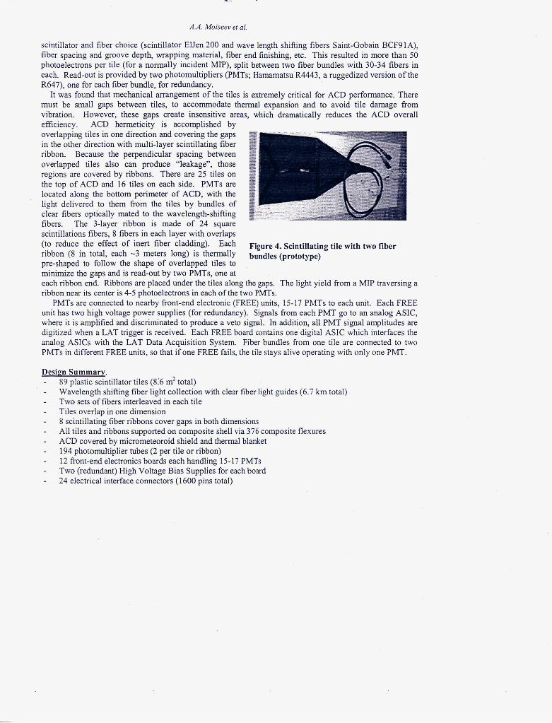
Plastic scintillator detectors were chosen as the basic ACD detectors since they are robust, inexpensive, well- understood, and have had extensive use in space experiments. Since the trade-off between backsplash ‘ sensitivity and charged particle detection efficiency was to be solved by careful adjustment of the detection signal threshold setting, each detector must have high uniformity of light collection over its area. Wavelength-shifting fibers were chosen to collect the light from ACD segments (called tiles) to meet this requirement (Figure 4). The tile design was optimized to maximize both the light yield and the uniformity to reduce signal fluctuations, which lead to inefficiency. In order to increase the light yield, a number of issues were studied
.- C l e a r f i y -- -& - cables
Figure 3. ACD detectors arrangement (4- th row tiles are not shown)
P
A.A. MoBeev et al.
scintillator and fiber choice (scintillator ElJen 200 and wave length shifting fibers Saint-Gobain BCF9 1 A), fiber spacing and groove depth, wrapping material, fiber end finishing, etc. This resulted in more than 50 photoelectrons per tile (for a normally incident MIP), split between two fiber bundles with 30-34 fibers in each. Read-out is provided by two photomultipliers (PMTs; Hamamatsu R4443, a ruggedized version of the R647), one for each fiber bundle, for redundancy.
It was found that mechanical arrangement of the tiles is extremely critical for ACD performance. There must be small gaps between tiles, to accommodate thermal expansion and to avoid tile damage from vibration. However. these eaus create insensitive areas, which dramatically reduces the ACD overall efficiency. ACD hermeticit; is accomplished by overlapping tiles in one direction and covering the gaps in the other direction with multi-layer scintillating fiber ribbon. Because the perpendicular spacing between overlapped tiles also can produce “leakage”, those regions are covered by ribbons. There are 25 tiles on the top of ACD and 16 tiles on each side. PMTs are located along the bottom perimeter of ACD, with the light delivered to them from the tiles by bundles of clear fibers optically mated to the wavelength-shifting fibers. The 3-layer ribbon is made of 24 square scintillations fibers, 8 fibers in each layer with overlaps (to reduce the effect of inert fiber cladding). Each ribbon (8 in total, each -3 meters long) is thermally pre-shaped to follow the shape of overlapped tiles to minimize the gaps and is read-out by two PMTs, one at
Figure 4. Scintillating tile with two fiber bundles (prototype)
each ribbon end. Ribbons are placed under the tiles along the gaps. The light yield from a MIP traversing a ribbon near its center is 4-5 photoelectrons in each of the two PMTs.
PMTs are connected to nearby front-end electronic (FREE) units, 15-17 PMTs to each unit. Each FREE unit has two high voltage power supplies (for redundancy). Signals from each PMT go to an analog ASIC, where it is amplified and discriminated to produce a veto signal. In addition, all PMT signal amplitudes are digitized when a LAT trigger is received. Each FREE board contains one digital ASIC which interfaces the analog ASICs with the LAT Data Acquisition System. Fiber bundles from one tile are connected to two PMTs in different FREE units, so that if one FREE fails, the tile stays alive operating with only one PMT.
Desim Summary. - - - - - - - - - - -
89 plastic scintillator tiles (8:6 m2 total) Wavelength shifting fiber light collection with clear fiber light guides (6.7 km total) Two sets of fibers interleaved in each tile Tiles overlap in one dimension 8 scintillating fiber ribbons cover gaps in both dimensions All tiles and ribbons supported on composite shell via 376 composite flexures ACD covered by micrometeoroid shield and thermal blanket 194 photomultiplier tubes (2 per tile or ribbon) 12 fkont-end electronics boards each handling 15-17 PMTs Two (redundant) High Voltage Bias Supplies for each board 24 electrical interface connectors (1600 pins total)

A.A. Moiseev et ai.
5. ACD Overall Performance
There is probably no reasonable way to determine directly the efficiency of ACD, because to do that it must be illuminated by an isotropic flux of charged particles uniformly from all sides. In order to determine the resulting efficiency, the entire ACD has been simulated, with carefully estimated light yield (different for each tile and fiber ribbon) and tile gaps corresponding to the expected ACD operating temperature of - 20C. The Geant 3.21 simulation package was used for both design optimization and performance determination. The light yield for each individual tile and ribbon was determined in laboratory tests using cosmic-ray muons, and simulation results for the gaps measured in assembled flight ACD are shown in Figure 5. Every tile fiber bundle has a different light signal output, mainly due to different length (and therefore
ACD Efficiency. Full Geometry
at&nuatioi) of fiber-bundles, and also to small variations in tile performance. PMT assignment to the tiles was based upon selection by photocathode quantum efficiency, to compensate for different light signals in the fiber bundles.
The principal result of the ACD performance analysis is that the efficiency requirement is met at a veto threshold setting of 0.3 of the mean MZP energy deposition. Backsplash analysis based on [4] showed that not more than 10% of 300GeV gamma-ray events otherwise accepted will be falsely rejected at this threshold, so ACD meets this requirement as well. Possible failure cases were analyzed, such as light reduction due to scintillator and/or fiber degradation, and electronics and/or PMT failure. PMT photocathode degradation was also taken into account. It was found (Figure 5) that ACD can tolerate the loss of one complete FREE board, and overall light loss up to 25%. The loss of several fibers per tile can also be tolerated without significant change in performance. It is seen from Figure 5 that fiber ribbons are critical for ACD performance; without the ribbons, ACD efficiency would be far below its efficiency requirement.
Figure 5. ACD overall emciency
6. Current Status of ACD
All ACD parts successfully passed all functional and environmental tests before being integrated. Currently (June 2005) ACD is fully integrated and undergoing functional and environmental tests (Figure 6). Final measurement of light yield for each tile is in progress.
c
7. References n.
1144,2003 2. Thompson, D.J. et al. ApJ Suppl., 86,629, 1993 3. Fichtel, C.E. et al. Astronomy & Astrophysics Suppl. Ser. 97,13,1993 4. Moiseev, A.A. et al. Astroparticle Physics, 22,215,2004
show fiber cables and PMTs)

![Diode detectors for RF measurement Part 1: Rectifier circuits, … · 2020. 6. 22. · (valve / tube) diode detector]. 7 Polynomial economization of envelope detector static characteristics,](https://img.pdfslide.net/doc/110x75/613172221ecc51586944bd8d/diode-detectors-for-rf-measurement-part-1-rectifier-circuits-2020-6-22-valve.jpg)

![Modules & components Xlin detector series...Thermo-electric cooler TE1, optional TE3 Pixel operability > 99 % Line rate 40 kHz 10 kHz Detector characteristics R0A 250-600[kΩcm2] Peak](https://img.pdfslide.net/doc/110x75/5e9bcec2946545560d0c574b/modules-components-xlin-detector-series-thermo-electric-cooler-te1-optional.jpg)