Embed Size (px)
Citation preview
Design and characterization of an integrated RemoteAccess Unit for wireless communicationRylander, K.; Latkowski, S.; Bente, E.A.J.M.; Broeke, R.; Tsiokos, D.; Pleros, N.; Sosa, A.;Tekin, T.; Bakker, A.Published in:Proceedings of IEICE Information and Communication Technology Forum 2016, 6-8 July 2016, Patras, Greece
Published: 01/01/2016
Document VersionPublisher’s PDF, also known as Version of Record (includes final page, issue and volume numbers)
Please check the document version of this publication:
• A submitted manuscript is the author's version of the article upon submission and before peer-review. There can be important differencesbetween the submitted version and the official published version of record. People interested in the research are advised to contact theauthor for the final version of the publication, or visit the DOI to the publisher's website.• The final author version and the galley proof are versions of the publication after peer review.• The final published version features the final layout of the paper including the volume, issue and page numbers.
Link to publication
Citation for published version (APA):Rylander, K., Latkowski, S., Bente, E. A. J. M., Broeke, R., Tsiokos, D., Pleros, N., ... Bakker, A. (2016). Designand characterization of an integrated Remote Access Unit for wireless communication. In M. Logothetis, & I.Moscholios (Eds.), Proceedings of IEICE Information and Communication Technology Forum 2016, 6-8 July2016, Patras, Greece (pp. 1-5). [V2]
General rightsCopyright and moral rights for the publications made accessible in the public portal are retained by the authors and/or other copyright ownersand it is a condition of accessing publications that users recognise and abide by the legal requirements associated with these rights.
• Users may download and print one copy of any publication from the public portal for the purpose of private study or research. • You may not further distribute the material or use it for any profit-making activity or commercial gain • You may freely distribute the URL identifying the publication in the public portal ?
Take down policyIf you believe that this document breaches copyright please contact us providing details, and we will remove access to the work immediatelyand investigate your claim.
Download date: 15. May. 2018
Design and characterization of an integratedRemote Access Unit for wireless communication
K. Rylander∗, S. Latkowski†, E. Bente†, R. Broeke‡, D. Tsiokos§, N. Pleros§, A. Sosa¶, T. Tekin¶ and A. Bakker∗∗PhoeniX Software, Hengelosestraat 705, 7521 PA Enschede, Netherlands
Email: [email protected]†COBRA Research Institute, Eindhoven University of Technology, Den Dolech 2, 5612AZ Eindhoven, Netherlands
‡Bright Photonics, Burgemeester van den Helmlaan 67, 3604 CE Maarssen, Netherlands§Center for Research and Technology Hellas, Aristotle University of Thessaloniki, P.O. Box 114, 54124 Thessaloniki, Greece
¶Research Center of Microperipheric Technologies,Technische Universitat Berlin, Gustav-Meyer-Allee 25, 13355 Berlin, Germany
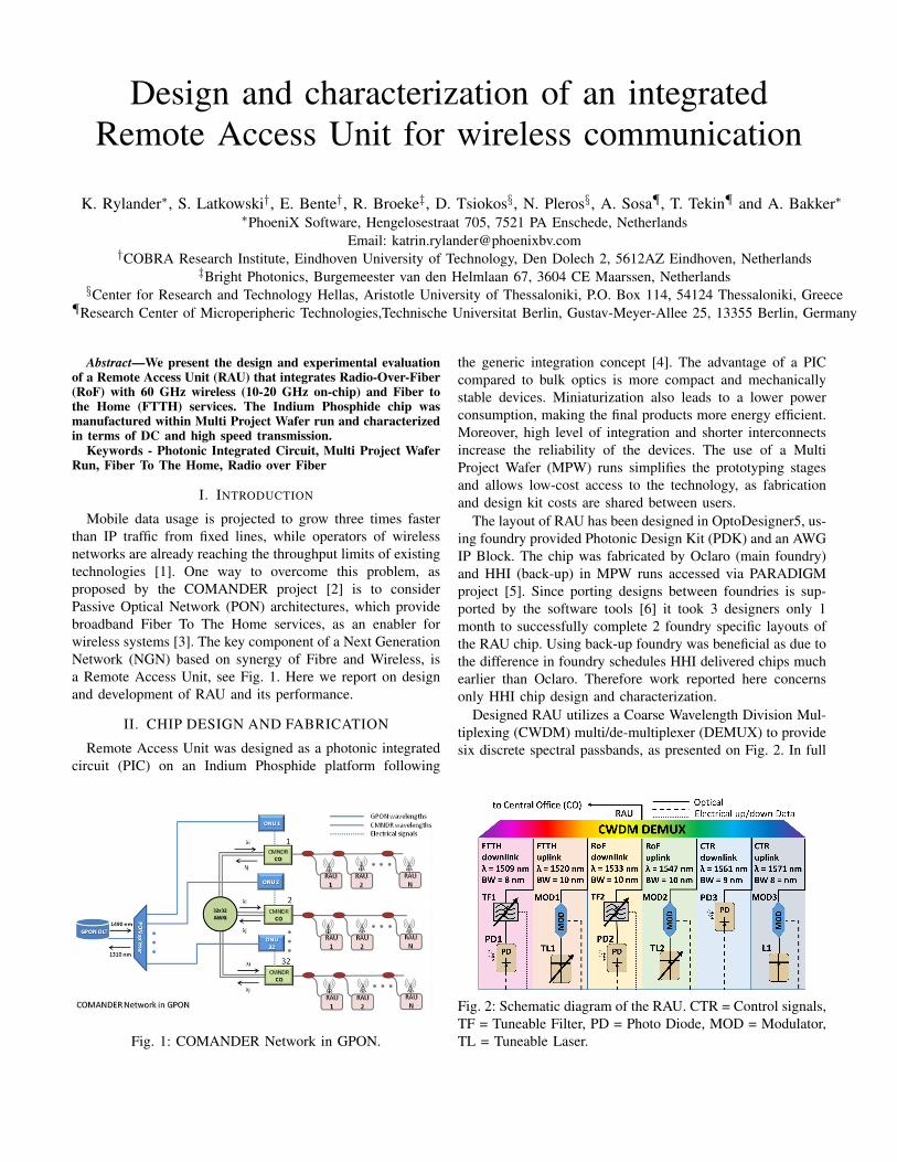
Abstract—We present the design and experimental evaluationof a Remote Access Unit (RAU) that integrates Radio-Over-Fiber(RoF) with 60 GHz wireless (10-20 GHz on-chip) and Fiber tothe Home (FTTH) services. The Indium Phosphide chip wasmanufactured within Multi Project Wafer run and characterizedin terms of DC and high speed transmission.
Keywords - Photonic Integrated Circuit, Multi Project WaferRun, Fiber To The Home, Radio over Fiber
I. INTRODUCTION
Mobile data usage is projected to grow three times fasterthan IP traffic from fixed lines, while operators of wirelessnetworks are already reaching the throughput limits of existingtechnologies [1]. One way to overcome this problem, asproposed by the COMANDER project [2] is to considerPassive Optical Network (PON) architectures, which providebroadband Fiber To The Home services, as an enabler forwireless systems [3]. The key component of a Next GenerationNetwork (NGN) based on synergy of Fibre and Wireless, isa Remote Access Unit, see Fig. 1. Here we report on designand development of RAU and its performance.
II. CHIP DESIGN AND FABRICATION
Remote Access Unit was designed as a photonic integratedcircuit (PIC) on an Indium Phosphide platform following
Fig. 1: COMANDER Network in GPON.
the generic integration concept [4]. The advantage of a PICcompared to bulk optics is more compact and mechanicallystable devices. Miniaturization also leads to a lower powerconsumption, making the final products more energy efficient.Moreover, high level of integration and shorter interconnectsincrease the reliability of the devices. The use of a MultiProject Wafer (MPW) runs simplifies the prototyping stagesand allows low-cost access to the technology, as fabricationand design kit costs are shared between users.
The layout of RAU has been designed in OptoDesigner5, us-ing foundry provided Photonic Design Kit (PDK) and an AWGIP Block. The chip was fabricated by Oclaro (main foundry)and HHI (back-up) in MPW runs accessed via PARADIGMproject [5]. Since porting designs between foundries is sup-ported by the software tools [6] it took 3 designers only 1month to successfully complete 2 foundry specific layouts ofthe RAU chip. Using back-up foundry was beneficial as due tothe difference in foundry schedules HHI delivered chips muchearlier than Oclaro. Therefore work reported here concernsonly HHI chip design and characterization.
Designed RAU utilizes a Coarse Wavelength Division Mul-tiplexing (CWDM) multi/de-multiplexer (DEMUX) to providesix discrete spectral passbands, as presented on Fig. 2. In full
Fig. 2: Schematic diagram of the RAU. CTR = Control signals,TF = Tuneable Filter, PD = Photo Diode, MOD = Modulator,TL = Tuneable Laser.
(a) (b)
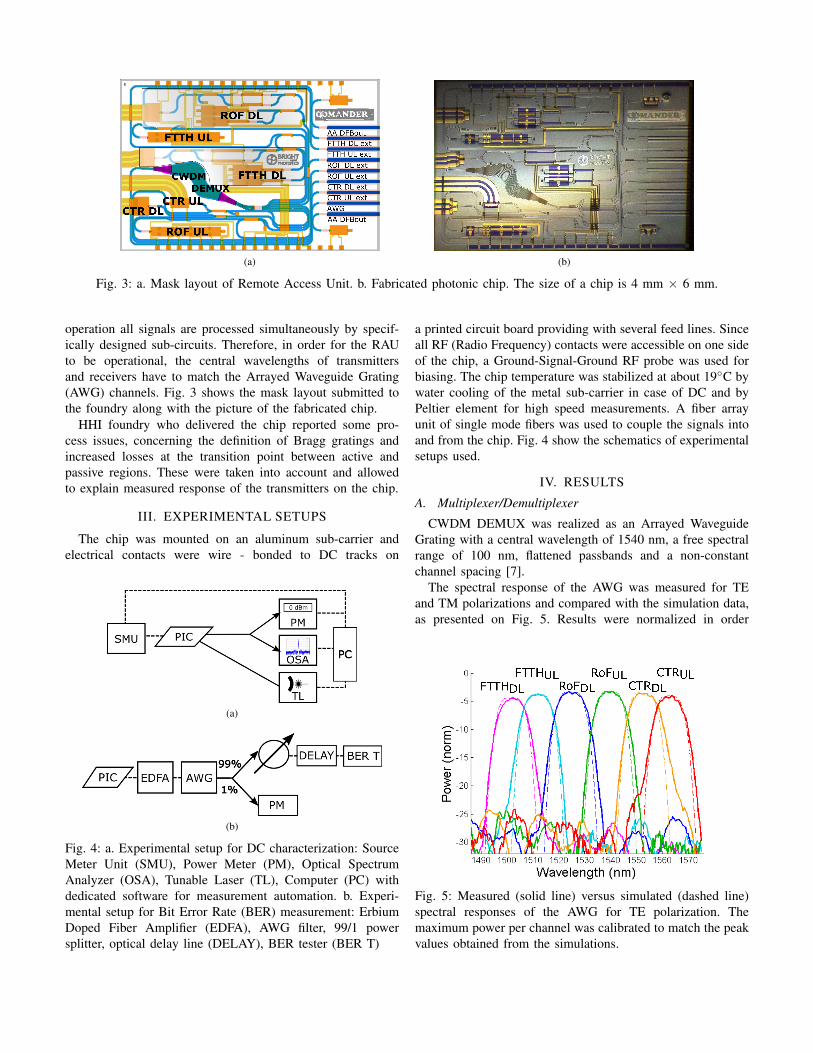
Fig. 3: a. Mask layout of Remote Access Unit. b. Fabricated photonic chip. The size of a chip is 4 mm × 6 mm.
operation all signals are processed simultaneously by specif-ically designed sub-circuits. Therefore, in order for the RAUto be operational, the central wavelengths of transmittersand receivers have to match the Arrayed Waveguide Grating(AWG) channels. Fig. 3 shows the mask layout submitted tothe foundry along with the picture of the fabricated chip.
HHI foundry who delivered the chip reported some pro-cess issues, concerning the definition of Bragg gratings andincreased losses at the transition point between active andpassive regions. These were taken into account and allowedto explain measured response of the transmitters on the chip.
III. EXPERIMENTAL SETUPS
The chip was mounted on an aluminum sub-carrier andelectrical contacts were wire - bonded to DC tracks on
(a)
(b)
Fig. 4: a. Experimental setup for DC characterization: SourceMeter Unit (SMU), Power Meter (PM), Optical SpectrumAnalyzer (OSA), Tunable Laser (TL), Computer (PC) withdedicated software for measurement automation. b. Experi-mental setup for Bit Error Rate (BER) measurement: ErbiumDoped Fiber Amplifier (EDFA), AWG filter, 99/1 powersplitter, optical delay line (DELAY), BER tester (BER T)
a printed circuit board providing with several feed lines. Sinceall RF (Radio Frequency) contacts were accessible on one sideof the chip, a Ground-Signal-Ground RF probe was used forbiasing. The chip temperature was stabilized at about 19◦C bywater cooling of the metal sub-carrier in case of DC and byPeltier element for high speed measurements. A fiber arrayunit of single mode fibers was used to couple the signals intoand from the chip. Fig. 4 show the schematics of experimentalsetups used.
IV. RESULTS
A. Multiplexer/Demultiplexer
CWDM DEMUX was realized as an Arrayed WaveguideGrating with a central wavelength of 1540 nm, a free spectralrange of 100 nm, flattened passbands and a non-constantchannel spacing [7].
The spectral response of the AWG was measured for TEand TM polarizations and compared with the simulation data,as presented on Fig. 5. Results were normalized in order
Fig. 5: Measured (solid line) versus simulated (dashed line)spectral responses of the AWG for TE polarization. Themaximum power per channel was calibrated to match the peakvalues obtained from the simulations.
(a) (b) (c)
(d) (e) (f)
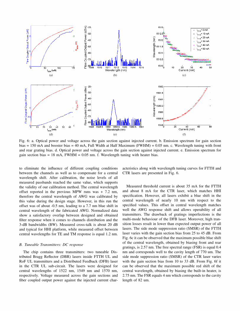
Fig. 6: a. Optical power and voltage across the gain section against injected current. b. Emission spectrum for gain sectionbias = 150 mA and booster bias = 40 mA, Full Width at Half Maximum (FWHM) = 0.05 nm. c. Wavelength tuning with frontand rear grating bias. d. Optical power and voltage across the gain section against injected current. e. Emission spectrum forgain section bias = 18 mA, FWHM = 0.05 nm. f. Wavelength tuning with heater bias.
to eliminate the influence of different coupling conditionsbetween the channels as well as to compensate for a centralwavelength shift. After calibration, the noise levels of allmeasured passbands reached the same value, which supportsthe validity of our calibration method. The central wavelengthoffset reported in the previous MPW runs was + 7.2 nm,therefore the central wavelength of AWG was calibrated bythis value during the design stage. However, in this run theoffset was of about -0.5 nm, leading to a 7.7 nm blue shift incentral wavelength of the fabricated AWG. Normalized datashow a satisfactory overlap between designed and obtainedfilter response when it comes to channels distribution and the3-dB bandwidths (BW). Measured cross-talk is about 20 dBand typical for HHI platform, while measured offset betweencentral wavelengths for TE and TM response is equal 1.2 nm.
B. Tuneable Transmitters: DC response
The chip contains three transmitters: two tuneable Dis-tributed Bragg Reflector (DBR) lasers inside FTTH UL andRoF UL transmitters and a Distributed Feedback (DFB) laserin the CTR UL sub-circuit. The lasers were designed forcentral wavelengths of 1522 nm, 1549 nm and 1570 nm,respectively. Voltage measured across the gain sections andfiber coupled output power against the injected current char-
acteristics along with wavelength tuning curves for FTTH andCTR lasers are presented in Fig. 6.
Measured threshold current is about 35 mA for the FTTHand about 8 mA for the CTR laser, which matches HHIspecification. However, all lasers exhibit a blue shift in thecentral wavelength of nearly 10 nm with respect to thespecified values. This offset in central wavelength matcheswell the AWG response shift and allows operability of alltransmitters. The drawback of gratings imperfections is themulti-mode behaviour of the DFB laser. Moreover, high tran-sition losses result in lower than expected output power of alllasers. The side mode suppression ratio (SMSR) of the FTTHlaser varies with the gain section bias from 25 to 45 dB. FromFig. 6c it can be observed that the maximum possible blue shiftof the central wavelength, obtained by biasing front and reargratings, is 2.57 nm. The free spectral range (FSR) is equal 0.4nm and corresponds well to the cavity length of 770 um. Theside mode suppression ratio (SMSR) of the CTR laser varieswith the gain section bias from 10 to 33 dB. From Fig. 6f itcan be observed that the maximum possible red shift of thecentral wavelength, obtained by biasing the built-in heater, is2.75 nm. The FSR equals 4 nm which corresponds to the cavitylength of 82 um.
(a) (b)
(c) (d)
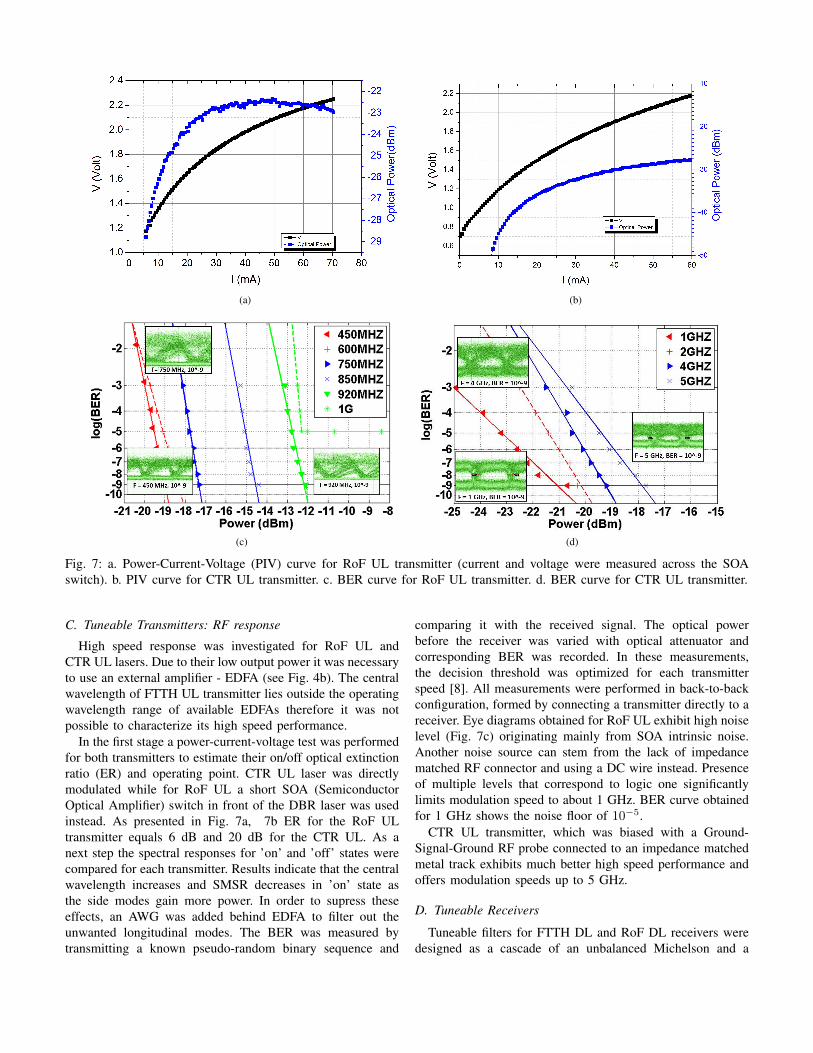
Fig. 7: a. Power-Current-Voltage (PIV) curve for RoF UL transmitter (current and voltage were measured across the SOAswitch). b. PIV curve for CTR UL transmitter. c. BER curve for RoF UL transmitter. d. BER curve for CTR UL transmitter.
C. Tuneable Transmitters: RF response
High speed response was investigated for RoF UL andCTR UL lasers. Due to their low output power it was necessaryto use an external amplifier - EDFA (see Fig. 4b). The centralwavelength of FTTH UL transmitter lies outside the operatingwavelength range of available EDFAs therefore it was notpossible to characterize its high speed performance.
In the first stage a power-current-voltage test was performedfor both transmitters to estimate their on/off optical extinctionratio (ER) and operating point. CTR UL laser was directlymodulated while for RoF UL a short SOA (SemiconductorOptical Amplifier) switch in front of the DBR laser was usedinstead. As presented in Fig. 7a, 7b ER for the RoF ULtransmitter equals 6 dB and 20 dB for the CTR UL. As anext step the spectral responses for ’on’ and ’off’ states werecompared for each transmitter. Results indicate that the centralwavelength increases and SMSR decreases in ’on’ state asthe side modes gain more power. In order to supress theseeffects, an AWG was added behind EDFA to filter out theunwanted longitudinal modes. The BER was measured bytransmitting a known pseudo-random binary sequence and
comparing it with the received signal. The optical powerbefore the receiver was varied with optical attenuator andcorresponding BER was recorded. In these measurements,the decision threshold was optimized for each transmitterspeed [8]. All measurements were performed in back-to-backconfiguration, formed by connecting a transmitter directly to areceiver. Eye diagrams obtained for RoF UL exhibit high noiselevel (Fig. 7c) originating mainly from SOA intrinsic noise.Another noise source can stem from the lack of impedancematched RF connector and using a DC wire instead. Presenceof multiple levels that correspond to logic one significantlylimits modulation speed to about 1 GHz. BER curve obtainedfor 1 GHz shows the noise floor of 10−5.
CTR UL transmitter, which was biased with a Ground-Signal-Ground RF probe connected to an impedance matchedmetal track exhibits much better high speed performance andoffers modulation speeds up to 5 GHz.
D. Tuneable Receivers
Tuneable filters for FTTH DL and RoF DL receivers weredesigned as a cascade of an unbalanced Michelson and a
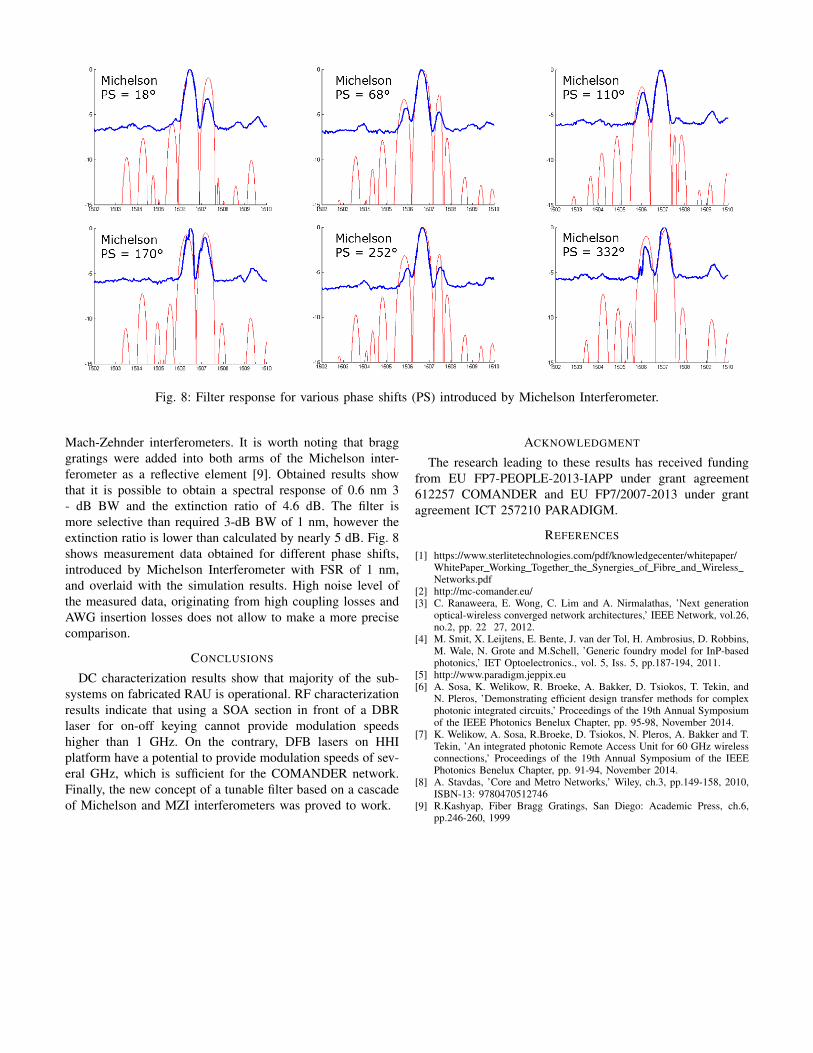
Fig. 8: Filter response for various phase shifts (PS) introduced by Michelson Interferometer.
Mach-Zehnder interferometers. It is worth noting that bragggratings were added into both arms of the Michelson inter-ferometer as a reflective element [9]. Obtained results showthat it is possible to obtain a spectral response of 0.6 nm 3- dB BW and the extinction ratio of 4.6 dB. The filter ismore selective than required 3-dB BW of 1 nm, however theextinction ratio is lower than calculated by nearly 5 dB. Fig. 8shows measurement data obtained for different phase shifts,introduced by Michelson Interferometer with FSR of 1 nm,and overlaid with the simulation results. High noise level ofthe measured data, originating from high coupling losses andAWG insertion losses does not allow to make a more precisecomparison.
CONCLUSIONS
DC characterization results show that majority of the sub-systems on fabricated RAU is operational. RF characterizationresults indicate that using a SOA section in front of a DBRlaser for on-off keying cannot provide modulation speedshigher than 1 GHz. On the contrary, DFB lasers on HHIplatform have a potential to provide modulation speeds of sev-eral GHz, which is sufficient for the COMANDER network.Finally, the new concept of a tunable filter based on a cascadeof Michelson and MZI interferometers was proved to work.
ACKNOWLEDGMENT
The research leading to these results has received fundingfrom EU FP7-PEOPLE-2013-IAPP under grant agreement612257 COMANDER and EU FP7/2007-2013 under grantagreement ICT 257210 PARADIGM.
REFERENCES
[1] https://www.sterlitetechnologies.com/pdf/knowledgecenter/whitepaper/WhitePaper Working Together the Synergies of Fibre and WirelessNetworks.pdf
[2] http://mc-comander.eu/[3] C. Ranaweera, E. Wong, C. Lim and A. Nirmalathas, ’Next generation
optical-wireless converged network architectures,’ IEEE Network, vol.26,no.2, pp. 22 27, 2012.
[4] M. Smit, X. Leijtens, E. Bente, J. van der Tol, H. Ambrosius, D. Robbins,M. Wale, N. Grote and M.Schell, ’Generic foundry model for InP-basedphotonics,’ IET Optoelectronics., vol. 5, Iss. 5, pp.187-194, 2011.
[5] http://www.paradigm.jeppix.eu[6] A. Sosa, K. Welikow, R. Broeke, A. Bakker, D. Tsiokos, T. Tekin, and
N. Pleros, ’Demonstrating efficient design transfer methods for complexphotonic integrated circuits,’ Proceedings of the 19th Annual Symposiumof the IEEE Photonics Benelux Chapter, pp. 95-98, November 2014.
[7] K. Welikow, A. Sosa, R.Broeke, D. Tsiokos, N. Pleros, A. Bakker and T.Tekin, ’An integrated photonic Remote Access Unit for 60 GHz wirelessconnections,’ Proceedings of the 19th Annual Symposium of the IEEEPhotonics Benelux Chapter, pp. 91-94, November 2014.
[8] A. Stavdas, ’Core and Metro Networks,’ Wiley, ch.3, pp.149-158, 2010,ISBN-13: 9780470512746
[9] R.Kashyap, Fiber Bragg Gratings, San Diego: Academic Press, ch.6,pp.246-260, 1999