Embed Size (px)
Citation preview

University of Texas at El Paso University of Texas at El Paso
ScholarWorks@UTEP ScholarWorks@UTEP
Open Access Theses & Dissertations
2020-01-01
Design And Characterization Of Thermal Inkjet Bioprinted Design And Characterization Of Thermal Inkjet Bioprinted
Constructs For The Treatment Of Diabetic Foot Ulcers And Other Constructs For The Treatment Of Diabetic Foot Ulcers And Other
Wound Healing Impaired Conditions Wound Healing Impaired Conditions
Luis Horacio Solis University of Texas at El Paso
Follow this and additional works at: https://scholarworks.utep.edu/open_etd
Part of the Biomedical Commons
Recommended Citation Recommended Citation Solis, Luis Horacio, "Design And Characterization Of Thermal Inkjet Bioprinted Constructs For The Treatment Of Diabetic Foot Ulcers And Other Wound Healing Impaired Conditions" (2020). Open Access Theses & Dissertations. 3042. https://scholarworks.utep.edu/open_etd/3042
This is brought to you for free and open access by ScholarWorks@UTEP. It has been accepted for inclusion in Open Access Theses & Dissertations by an authorized administrator of ScholarWorks@UTEP. For more information, please contact [email protected].
DESIGN AND CHARACTERIZATION OF THERMAL INKJET BIOPRINTED
CONSTRUCTS FOR THE TREATMENT OF DIABETIC FOOT ULCERS
AND OTHER WOUND HEALING IMPAIRED CONDITIONS
LUIS HORACIO SOLIS
Doctoral Program in Biomedical Engineering
APPROVED:
Thomas Boland, Ph.D., Chair
Renato Aguilera, Ph.D.
Tamis Bright, M.D.
Robert Kirken, Ph.D.
Stephen L. Crites, Jr., Ph.D.
Dean of the Graduate School

Copyright ©
by
Luis H. Solis
2020

Dedication
To my beautiful family:
My wife, Cynthia, mi chango, Ivette, y a mi pollito, Luis Horacio II
To my parents:
Ramiro Horacio and Carlota Amalia
To my brothers:
Ramiro CeAcatl and Carlos German
To my committee members:
Dr. Thomas Boland, Dr. Renato Aguilera, Dr. Tamis Bright, and Dr. Robert Kirken
DESIGN AND CHARACTERIZATION OF THERMAL INKJET BIOPRINTED
CONSTRUCTS FOR THE TREATMENT OF DIABETIC FOOT ULCERS
AND OTHER WOUND HEALING IMPAIRED CONDITIONS
by
LUIS HORACIO SOLIS, MPH
DISSERTATION
Presented to the Faculty of the Graduate School of
The University of Texas at El Paso
in Partial Fulfillment
of the Requirements
for the Degree of
DOCTOR OF PHILOSOPHY
Biomedical Engineering
THE UNIVERSITY OF TEXAS AT EL PASO
May 2020

v
Acknowledgements
I would like to thank Dr. Thomas Boland for allowing me to be part of his research group.
I thank him for his guidance and assistance, as well as for the lab space, equipment, and supplies
that he furnished in order to complete this work. I would also like to acknowledge my committee
members, Dr. Renato Aguilera, Dr. Tamis Bright, and Dr. Robert Kirken for providing me with
their open accessibility and valuable time to discuss molecular biology concepts and experimental
setup designs during my Ph.D. education.
I thank all my friends for all the many hours working inside and outside of the lab, Julio
Rincon, Carlos Serna III, Michael Furth, Aleli Mojica-Campbell, Yoshira Ayala, Emmanuel
Utreras, Alfredo Ornelas, Mario Cano (whose office and home were also a blessing in my final
hours of writing), Luis Barrera, and Andrew Pardo. My sincerest appreciation to our collaborators,
Denisse Gutierrez, and Dr. Armando Varela-Ramirez, whom I consider my mentor and a huge
strength of the BBRC. Yoshira Ayala, and Susana Portillo, without whom these results would not
have been realized. I would like to make a special acknowledgement to Beu Oropeza, Daisy
Alvarado, Valeria Altamirano, Jesus Cedeno, Dante Chaparro Vega, Octavio Cordova, Isaac
Deaguero, Erwin Delgado, Jesus Castor, Mirsa Gonzalez-Favela, Michael Furth, Mario Garcia,
Alba Leyva, Emilio Loera, Gisela Lopez, Fernanda Lugo, Tania Miramontes, Erik Munoz, Paola
Rodriguez, Carlos Serna III, Leila Subia, and Arahim Zuniga-Herrera for their contribution in our
in vivo data as a result of the BME histology course.
My deepest gratitude to Dr. Aguilera for providing and allowing me to be part of the RISE
program under the Department of Biological Sciences. Additionally, I am exceptionally grateful
to Dr. Isela Ocegueda, Dr. Aaron Waggoner, and Dr. Shannon Connelly from the UTEP Graduate

vi
School for awarding me two Dodson Research Grants plus the Dissertation Completion Fellowship
Award which again without all of this funding this work would not have been possible.
I would like to give a special acknowledgement to my wife and kids. Thank you Panchita
for giving me two incredible kids and for all your understanding and unwavering support
throughout my educational responsibilities. Thank you Chango for all your love and for showing
me how beautiful it is to be a dad. Thank you Pollito for being an amazing blessing and addition
to our wonderful family. We were dying to meet you and now that you are here, we can’t wait to
hear you laugh and talk.
vii
Abstract
Tissue engineering (TE) is a multidisciplinary practice focused on developing patient-
specific constructs to repair, regenerate, or replace injured tissues and organs. One biofabrication
process that has gained tremendous momentum in this field is bioprinting. Most, if not all
bioprinting modalities embody the same principles of heat and shear due to mechanical forces or
friction as cells are forced through narrow orifices. While it is important to examine the interaction
between host and implanted constructs, it is also crucial to understand the direct effects that these
bioprinting technologies have on cells before embedding them into TE applications.
The purpose of this work is to determine the effects of thermal inkjet bioprinting (TIB) on
cellular angiogenesis in vitro. Our in vivo histological analysis of implanted constructs containing
TIB endothelial cells (ECs) in B-17SCID mice demonstrated significantly higher number of
capillary-like structures as compared to constructs with manually pipetted (MP) ECs. Additionally,
in vitro cellular morphological differences between TIB- and MP-ECs were noted. TIB cells had
elongated protrusions at 5–6 times the size of MP cells. Moreover, an Annexin V-FITC and PI
apoptosis assay showed a 75% apoptosis among TIB cells as compared to MP cells via flow
cytometry analysis. After a 3-day incubation period, however, TIB cells demonstrated significantly
higher viability as compared to the control group. Also, cytokine expression was assessed with the
use of Milliplex magnetic bead panels, which confirmed significant overexpression of HSP70, IL-
1α, VEGF-A, IL-8, and FGF-1 among TIB cells as compared to the control. Furthermore, a Human
phospho-kinase array to determine intracellular kinase and protein activation showed a significant
over activation of HSP27 and HSP60 in TIB cells as compared to MP cells as well as a decreased
proliferative state among TIB-ECs.
viii
In all, we have demonstrated that constructs containing TIB-ECs offers an alternative
method to inducing microvascular networks in vivo. Our in vitro data also supports our findings
as they translate in vivo. The ability to create vast capillary networks, coupled with the fixed
printing parameters of our TIB technology (i.e. heat, pressure, nozzle size, droplet size, and
velocity) allows for versatile and repeatable means to create these constructs. Future in vitro work
with appropriate controls for mechanical stress or possibly printing with the cartridge submerged
within media to control for cellular stretching are recommended. Also, in vivo work with impaired
wound healing such as a diabetic foot ulcer model are also suggested. Finally, a comparative study
among different TIB modalities are also recommended. Looking ahead, bioengineered constructs
using our TIB technology may find potential applications in organ on a chip, drug testing, and
autonomic healing applications.
ix
Table of Contents
Dedication ...................................................................................................................................... iii
Acknowledgements ..........................................................................................................................v
Abstract ......................................................................................................................................... vii
Table of Contents ........................................................................................................................... ix
List of Tables ................................................................................................................................. xi
List of Figures ............................................................................................................................... xii
Chapter 1: Introduction ....................................................................................................................1
Dissertation Overview ...................................................................................................1
Chapter 2: Literature Review ...........................................................................................................2
2.1 Diabetic Foot Ulcers ................................................................................................2
2.2 Wound Management Practices for DFUs ................................................................2
2.2.1 Offloading Devices ......................................................................................2
2.2.2 Tissue Engineered Skin Substitutes .............................................................3
2.3 Wound Healing ........................................................................................................4
2.4 Tissue Engineering Challenge: Angiogenesis .........................................................4
Chapter 3: Thermal Inkjet Bioprinting (TIB): A Promising Approach to Angiogenic
Induction .................................................................................................................................5
3.1 TIB Technology .......................................................................................................5
3.2 In Vitro Microvasculature Fabrication using TIB Technology................................8
3.3 TIB Technology Induces Angiogenesis ...................................................................8
3.4 Materials and Methods .............................................................................................9
3.5 Results and Discussion ..........................................................................................12
3.6 Conclusion .............................................................................................................14
Chapter 4: TIB Elicits Morphological Changes, Cytokine Expression, and Kinase Activation
In Vitro ..................................................................................................................................15
4.1 Introduction ............................................................................................................15
4.2 Materials and Methods ...........................................................................................16
4.3 Results and Discussion ..........................................................................................20

x
4.4 Conclusion .............................................................................................................39
Chapter 5: Conclusions, Limitations, and Future Work ................................................................40
References ......................................................................................................................................42
Glossary .........................................................................................................................................55
Vita ...............................................................................................................................................57

xi
List of Tables
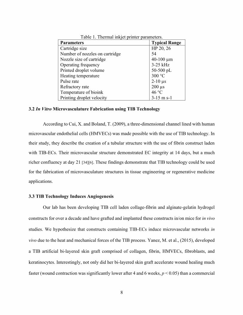
Table 1. Thermal inkjet printer parameters. .................................................................................... 8 Table 2. List of treatment groups and type of implanted construct. ............................................. 11 Table 3. List of kinases and proteins by category and function. ................................................... 34
xii
List of Figures
Figure 1. Mechanism behind the TIB technology. ......................................................................... 6 Figure 2. High speed photographs showing droplets ejected from drop-on-demand inkjet nozzles
(Reproduced and rearranged from the original images to demonstrate the sequence of events
while retaining the original content from a PowerPoint attachment from Dr. Ian Hutchings,
Institute of Manufacturing at The University of Cambridge via email correspondence). .............. 7
Figure 3. Demonstration of TIB droplets. ....................................................................................... 7 Figure 4. Histological analysis of excised subcutaneous tissue samples demonstrating the
differences in capillary-like structures by treatment group. ......................................................... 13 Figure 5. Bar graph demonstrating the mean number of vessels by implant type. ....................... 14 Figure 6. Cell morphology between TIB and MP HMVECs after a 24-hour incubation period. . 21
Figure 7. Flow cytometry analysis demonstrating phophatidylserine (PtdSer) externalization for
TIB and MP HMVECs after a 24-hour incubation period. ........................................................... 23 Figure 8. Flow cytometry analysis of a PI exclusion assay demonstrating cell viability
percentages between TIB and MP-HMVECs at 3 and 7-day incubation periods. ........................ 25
Figure 9. Time course expression of six specifically selected cytokines by treatment group. ..... 29 Figure 10. In vitro Milliplex magnetic bead panel analysis of six specifically selected cytokines
after a 12-hour incubation period. ................................................................................................. 31
Figure 11. In vitro Human phosphor-kinase array analysis of the activation of 43 kinases and two
proteins after a 12-hour incubation period. ................................................................................... 33
Figure 12. Molecular mechanisms involved in RTK, cytokine receptor, heat stress, integrin, and
GPCR signaling. ........................................................................................................................... 37

1
Chapter 1: Introduction
Tissue engineering (TE) is a multidisciplinary practice focused on developing patient-
specific constructs to repair, regenerate, or replace injured tissues and organs. Using a combination
of biomaterials, cells, growth factors, and engineering technologies, artificial tissues can be created
to regenerate or repair their injured counterparts. One biofabrication process that has gained
tremendous momentum in this field is bioprinting. Little is known, however, about the direct
effects that the bioprinting process inflicts on cells. Most, if not all bioprinting modalities embody
the same principles of heat and shear due to mechanical forces or friction as cells are forced
through narrow orifices. While it is important to examine the interaction between host and
implanted bioengineered constructs, it is also crucial to understand the direct effects that these
bioprinting technologies have on cells before embedding them into TE applications.
Understanding these direct effects could facilitate in improving construct designs or to optimize
the desired outcomes. The purpose of this work is to determine the effects of thermal inkjet
bioprinting (TIB) on cellular angiogenesis in vitro.
Dissertation Overview
In Chapter 2, a literature review is provided focusing on diabetic foot ulcers (DFUs), the
wound healing process, as well as the current treatments for DFUs. In Chapter 3, a brief history of
the TIB technology along with its mechanism are described. Moreover, the induction of in vivo
microvascular networks among implanted constructs with TIB-EC are reported. In Chapter 4, in
vitro characterization of TIB-ECs is defined, including cell morphology, cell viability, cytokine
expression, and kinase phosphorylation. Finally, the key conclusions of my Ph.D. work along with
the limitations and future work recommendations are summarized in Chapter 5.
2
Chapter 2: Literature Review
2.1 Diabetic Foot Ulcers
Diabetic foot ulcers (DFUs) remain a serious complication of diabetes resulting in
significant morbidity, mortality, and healthcare expenses among patients. There were 285 million
people affected by diabetes in 2010 and more than 366 million are projected to have this disease
by 2030 [1][2]. DFUs affect 15-34% of all diabetic patients within their lifetime [1][2][3][4], resulting
in 84% of all lower-leg amputations worldwide [2][3][5][6][7][8]. This translates into a leg being
amputated every 30 seconds around the world [1]. Most alarming is the 44% mortality rate within
the first year after an amputation [9], which becomes 30-50% within 3 years [10], and 77% within
5 years [9][7]. In addition to the high burden of medical expenses [1]. The cost for the management
of DFUs in the U.S. is between $9-13 billion annually [8]. Current treatment modalities consist of
offloading devices and artificial skin substitutes.
2.2 Wound Management Practices for DFUs
2.2.1 Offloading Devices
Total contact casts (TCCs) and removable cast walkers (RCWs) are the most commonly
used offloading devices used for the treatment of DFUs. TCCs are universally recognized as the
gold standard devices for the treatment of DFUs [11][12][13][14][15][16][8]; however, patient usage
compliance is relatively low. Armstrong et al. [11] monitored DFU patients being treated with a
RCW device for seven days and found a 28% compliance rate. Reasons for poor compliance
among patients include, impaired daily activities such as sleeping or showering and worsening
postural instability [12]. Crews et al. [16] found that postural instability was strongly associated
with poor offloading treatment compliance due to the device being bulky and heavy and having
forced fixation, resulting in changes with the patient’s normal gait. They note that even among
healthy individuals, gait, balance, and reaching functionality are all affected when an offloading
boot is worn. Thus, in comparison to diabetic patients who suffer from neuropathy-related changes,
3
the challenges observed among healthy individuals might be more pronounced in DFU patients
who wear these offloading devices [16]. Not only is compliance low among patients, but clinicians
are not implementing their use, which is concerning. Among 901 clinics in 48 states and D.C.,
only 1.7% used TCCs for the treatment of DFUs; 15.2% used RWCs; 2.6% used other devices
such as therapeutic shoes; and 12.3% used complete non-weight-bearing (NWB) devices such as
crutches and wheelchairs. Interestingly, 58.1% did not consider TCCs as the golf standard of
treatment for DFUs and 45.5% did not use TCCs as an offloading device [12]. The authors conclude
that in reality, clinicians understand that reducing pressure, shear, and repetitive injury do
dramatically affect the outcomes of DFU treatments; however, when it comes to TCCs, their
application requires skill, they are labor intensive, and the procedure is time consuming [8] and
clinics may not have the necessary manpower available [12]. Also, the low percentage use of RCWs
might be related to issues of cost and lack of reimbursement in the U.S. For these reasons clinicians
tend to use other offloading methods for the treatment of DFUs [12] and/or make use of advanced
wound care technologies such as artificial skin substitutes.
2.2.2 Tissue Engineered Skin Substitutes
Artificial skin substitutes were developed to assist in the treatment of superficial wounds.
These skin substitutes are divided into two groups: allogenic cell-containing constructs, such as
Apligraf and Dermagraft, and acellular matrices like Oasis and MatriStem [17]. In a systematic
review for the treatment of DFUs with skin substitutes, researchers concluded that compared to
treatment alone, additional treatment with skin substitutes, could reduce the healing time of DFUs
and decrease the need for amputations [18]. However, skin substitutes are relatively expensive,
especially since treatment of a DFU lasts several months and numerous skin substitute applications
are needed ($5,000 for cell-containing constructs vs $2,000 for acellular matrices for the same
length of time to heal a DFU). Interestingly, the authors found no conclusive evidence for the
effectiveness between the two types of skin substitutes in the treatment of DFUs [17].
4
While these skin substitutes provide the adequate wound healing parameters (e.g. low pH,
moisture, antimicrobial ingredients, etc.), they do not provide the angiogenic properties required
for proper wound healing. Key proangiogenic factors include fibroblast growth factor 2 (FGF-2),
interleukin 8 (IL-8), platelet-derived growth factor (PDGF), placental growth factor (PlGF),
transforming growth factor-β, and vascular endothelial growth factor (VEGF) [19].
2.3 Wound Healing
The wound healing process occurs in four major steps: a) hemostatic, b) inflammatory, c)
proliferative, and d) remodeling [20]. Granulation tissue, which forms during the proliferative
stage, is the hallmark of a positive wound healing response. It is during this step that fibrovascular
tissue containing fibroblasts, capillaries, and collagen is formed [21]. Not only is angiogenesis
critical for the formation of granulation tissue [20][21][22][23], but it is also necessary to transfer
of nutrients and oxygen in addition to removing waste metabolites from the wounded area as it
promotes the regeneration of new tissue [21][22].
2.4 Tissue Engineering Challenge: Angiogenesis
Current tissue engineering strategies for the induction of angiogenesis include scaffold
design such as sacrificial constructs, material functionalization, microfabrication, and bioreactors.
Additionally, genetic manipulation strategies through stem cells, miRNA induction, and synthetic
polymers have demonstrate great strides in vascularization efforts [24]. Despite all this progress,
the challenges of architecture, biological control, bioavailability, biodegradability, host immune
responses, stem cell fate, and the understanding of biomolecular signaling pathways of angiogenic
induction remain. Comprehensive reviews on all these different approaches have been recently
published [25][26][27][24].
5
Chapter 3: Thermal Inkjet Bioprinting (TIB): A Promising Approach to Angiogenic
Induction
3.1 TIB Technology
Bioprinting is the process of depositing cells with the help of a modified printer. More
specifically, thermal inkjet bioprinting (TIB) technology has the ability to deliver cells, growth
factors, and biomaterial scaffolds to create various shapes and thickness with digital control [6].
The thermal inkjet printer is one of the oldest printing technologies using drop-on-demand (DOD)
technology patented in 1951 [28]. In 2003, Cris Wilson and Thomas Boland were the first pioneers
to modify an HP 660C desktop thermal inkjet printer for the purposes of printing proteins and cells
for drug screening and tissue engineering applications [29]. Furthermore, Boland et al., 2003,
demonstrated that 3D layer by layer constructs could be developed using a thermosensitive gel
with the use of TIB technology [30].
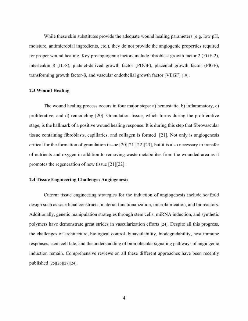
The printing process of TIB can be conceptualized in three steps as depicted in Figure 1:
1) the heating of thermal actuator or resistor inside the chamber of a modified ink cartridge heats
up to approximately 300 °C for 2 microseconds [6]; 2) a bioink bubble forms on the surface of the
resistor which will eventually produce enough pressure to overcome the surface tension; and 3)
bioink droplets are ejected out of the cartridge nozzles as bubbles collapse inside the chamber [28].
This process repeats throughout the bioprinting process in pulses of 10 µs. Modeling experiments
demonstrate that the initial 300 °C heat of the resistor actually disperses into the bioink and its
kinetic energy resulting in an actual temperature between 4 and 10 degrees above the ambient
temperature thus useful for bioprinting applications [6][31].
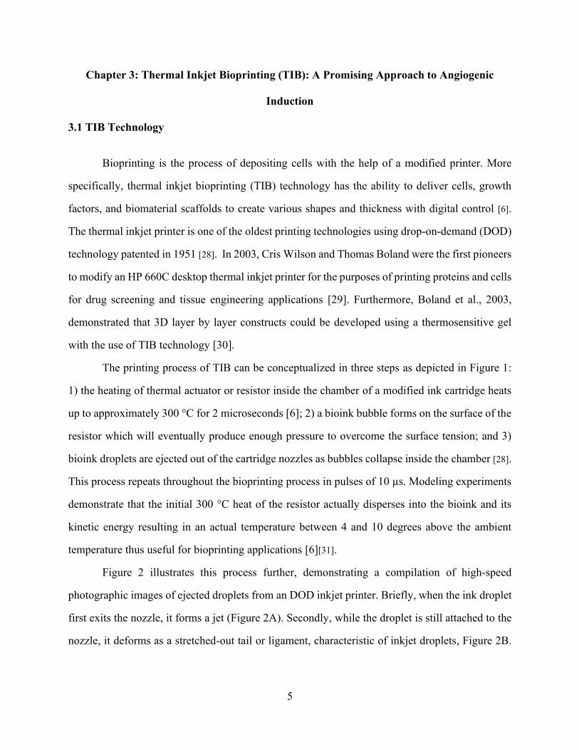
Figure 2 illustrates this process further, demonstrating a compilation of high-speed
photographic images of ejected droplets from an DOD inkjet printer. Briefly, when the ink droplet
first exits the nozzle, it forms a jet (Figure 2A). Secondly, while the droplet is still attached to the
nozzle, it deforms as a stretched-out tail or ligament, characteristic of inkjet droplets, Figure 2B.
6
Finally, while part of the drop returns to the nozzle, the complete tail joins the ejected drop and
may break up into small satellite drops, Figure 2C [32].
Figure 1. Mechanism behind the TIB technology.
1) Vapor bubbles develop on the heating element. 2) Formation of a larger vapor bubble. 3) The
vapor bubble collapses and a single drop of ink is ejected.
7
Figure 2. High speed photographs showing droplets ejected from drop-on-demand inkjet nozzles
(Reproduced and rearranged from the original images to demonstrate the sequence
of events while retaining the original content from a PowerPoint attachment from
Dr. Ian Hutchings, Institute of Manufacturing at The University of Cambridge via
email correspondence).
A) Jet of ink stretching out from an inkjet nozzle. B) Elongated tail of droplet connected to the
inkjet nozzle. C) Midair inkjet droplets demonstrating the elongated tails attached to the droplets
and formation of smaller satellite drops.
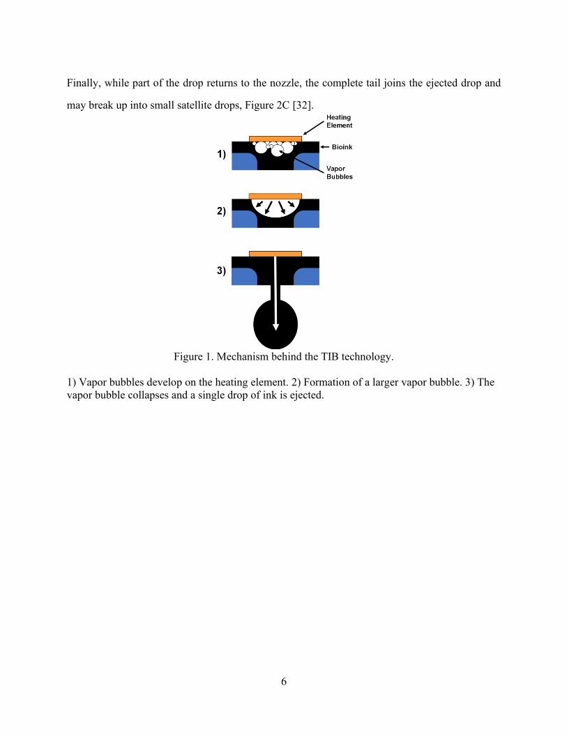
Figure 3. Demonstration of TIB droplets.
A) TIB droplets on a Petri dish. B) TIB-ECs on an alginate construct. ECs appear in blue due to
DAPI staining. Notice that almost every bioink droplet contained a single cell as well as the
impressions from smaller satellite droplets. C) Topology of a TIB alginate construct demonstrating
droplet impressions.
For the purposes of this entire project, a more complete description of the thermal inkjet
printer developed in our laboratory can be found in De Maria, C., et al. 2010 [33]. Table 1 depicts
the typical range parameters for thermal inkjet printers.
8
Table 1. Thermal inkjet printer parameters.
Parameters Typical Range
Cartridge size
Number of nozzles on cartridge
Nozzle size of cartridge
Operating frequency
Printed droplet volume
Heating temperature
Pulse rate
Refractory rate
Temperature of bioink
Printing droplet velocity
HP 20, 26
54
40-100 µm
3-25 kHz
50-500 pL
300 °C
2-10 µs
200 µs
46 °C
3-15 m s-1
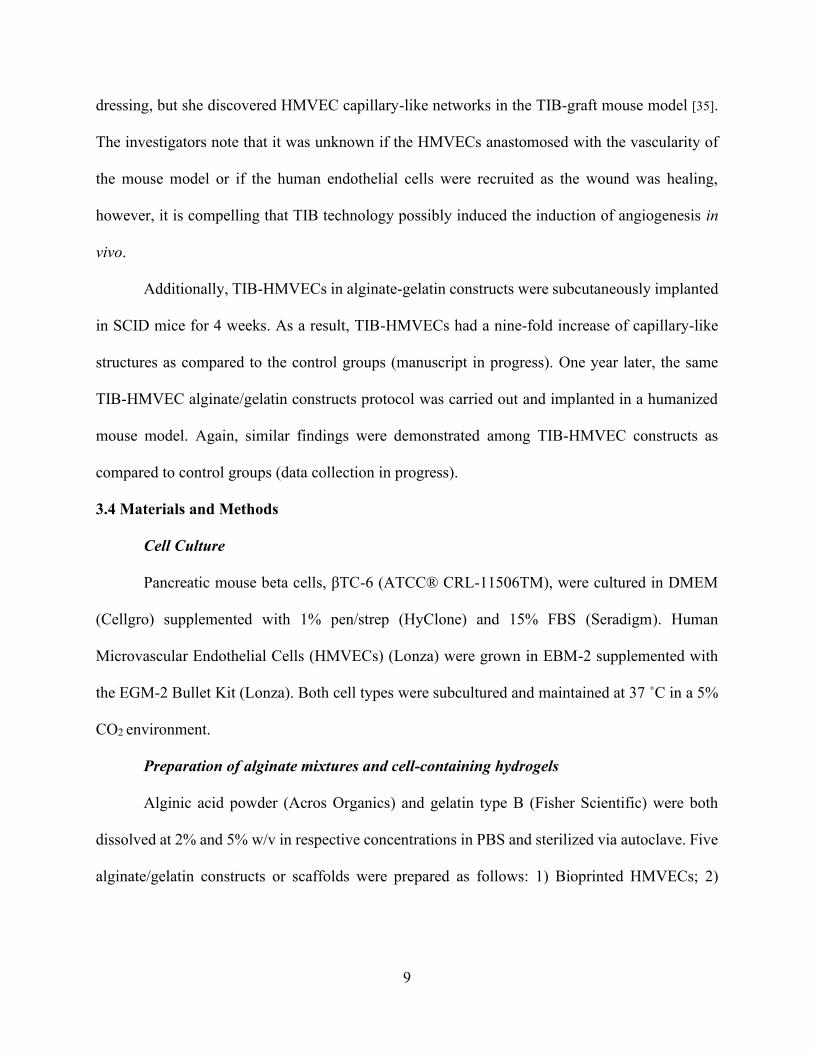
3.2 In Vitro Microvasculature Fabrication using TIB Technology
According to Cui, X. and Boland, T. (2009), a three-dimensional channel lined with human
microvascular endothelial cells (HMVECs) was made possible with the use of TIB technology. In
their study, they describe the creation of a tubular structure with the use of fibrin construct laden
with TIB-ECs. Their microvascular structure demonstrated EC integrity at 14 days, but a much
richer confluency at day 21 [34][6]. These findings demonstrate that TIB technology could be used
for the fabrication of microvasculature structures in tissue engineering or regenerative medicine
applications.
3.3 TIB Technology Induces Angiogenesis
Our lab has been developing TIB cell laden collage-fibrin and alginate-gelatin hydrogel
constructs for over a decade and have grafted and implanted these constructs in/on mice for in vivo
studies. We hypothesize that constructs containing TIB-ECs induce microvascular networks in
vivo due to the heat and mechanical forces of the TIB process. Yanez, M. et al., (2015), developed
a TIB artificial bi-layered skin graft comprised of collagen, fibrin, HMVECs, fibroblasts, and
keratinocytes. Interestingly, not only did her bi-layered skin graft accelerate wound healing much
faster (wound contraction was significantly lower after 4 and 6 weeks, p < 0.05) than a commercial
9
dressing, but she discovered HMVEC capillary-like networks in the TIB-graft mouse model [35].
The investigators note that it was unknown if the HMVECs anastomosed with the vascularity of
the mouse model or if the human endothelial cells were recruited as the wound was healing,
however, it is compelling that TIB technology possibly induced the induction of angiogenesis in
vivo.
Additionally, TIB-HMVECs in alginate-gelatin constructs were subcutaneously implanted
in SCID mice for 4 weeks. As a result, TIB-HMVECs had a nine-fold increase of capillary-like
structures as compared to the control groups (manuscript in progress). One year later, the same
TIB-HMVEC alginate/gelatin constructs protocol was carried out and implanted in a humanized
mouse model. Again, similar findings were demonstrated among TIB-HMVEC constructs as
compared to control groups (data collection in progress).
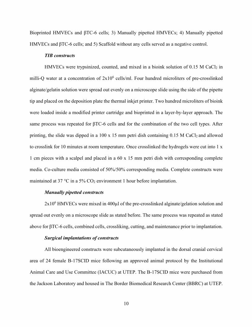
3.4 Materials and Methods
Cell Culture
Pancreatic mouse beta cells, βTC-6 (ATCC® CRL-11506TM), were cultured in DMEM
(Cellgro) supplemented with 1% pen/strep (HyClone) and 15% FBS (Seradigm). Human
Microvascular Endothelial Cells (HMVECs) (Lonza) were grown in EBM-2 supplemented with
the EGM-2 Bullet Kit (Lonza). Both cell types were subcultured and maintained at 37 ˚C in a 5%
CO2 environment.
Preparation of alginate mixtures and cell-containing hydrogels
Alginic acid powder (Acros Organics) and gelatin type B (Fisher Scientific) were both
dissolved at 2% and 5% w/v in respective concentrations in PBS and sterilized via autoclave. Five
alginate/gelatin constructs or scaffolds were prepared as follows: 1) Bioprinted HMVECs; 2)
10
Bioprinted HMVECs and βTC-6 cells; 3) Manually pipetted HMVECs; 4) Manually pipetted
HMVECs and βTC-6 cells; and 5) Scaffold without any cells served as a negative control.
TIB constructs
HMVECs were trypsinized, counted, and mixed in a bioink solution of 0.15 M CaCl2 in
milli-Q water at a concentration of 2x10⁶ cells/ml. Four hundred microliters of pre-crosslinked
alginate/gelatin solution were spread out evenly on a microscope slide using the side of the pipette
tip and placed on the deposition plate the thermal inkjet printer. Two hundred microliters of bioink
were loaded inside a modified printer cartridge and bioprinted in a layer-by-layer approach. The
same process was repeated for βTC-6 cells and for the combination of the two cell types. After
printing, the slide was dipped in a 100 x 15 mm petri dish containing 0.15 M CaCl2 and allowed
to crosslink for 10 minutes at room temperature. Once crosslinked the hydrogels were cut into 1 x
1 cm pieces with a scalpel and placed in a 60 x 15 mm petri dish with corresponding complete
media. Co-culture media consisted of 50%/50% corresponding media. Complete constructs were
maintained at 37 °C in a 5% CO2 environment 1 hour before implantation.
Manually pipetted constructs
2x10⁶ HMVECs were mixed in 400µl of the pre-crosslinked alginate/gelation solution and
spread out evenly on a microscope slide as stated before. The same process was repeated as stated
above for βTC-6 cells, combined cells, crossliking, cutting, and maintenance prior to implantation.
Surgical implantations of constructs
All bioengineered constructs were subcutaneously implanted in the dorsal cranial cervical
area of 24 female B-17SCID mice following an approved animal protocol by the Institutional
Animal Care and Use Committee (IACUC) at UTEP. The B-17SCID mice were purchased from
the Jackson Laboratory and housed in The Border Biomedical Research Center (BBRC) at UTEP.
11
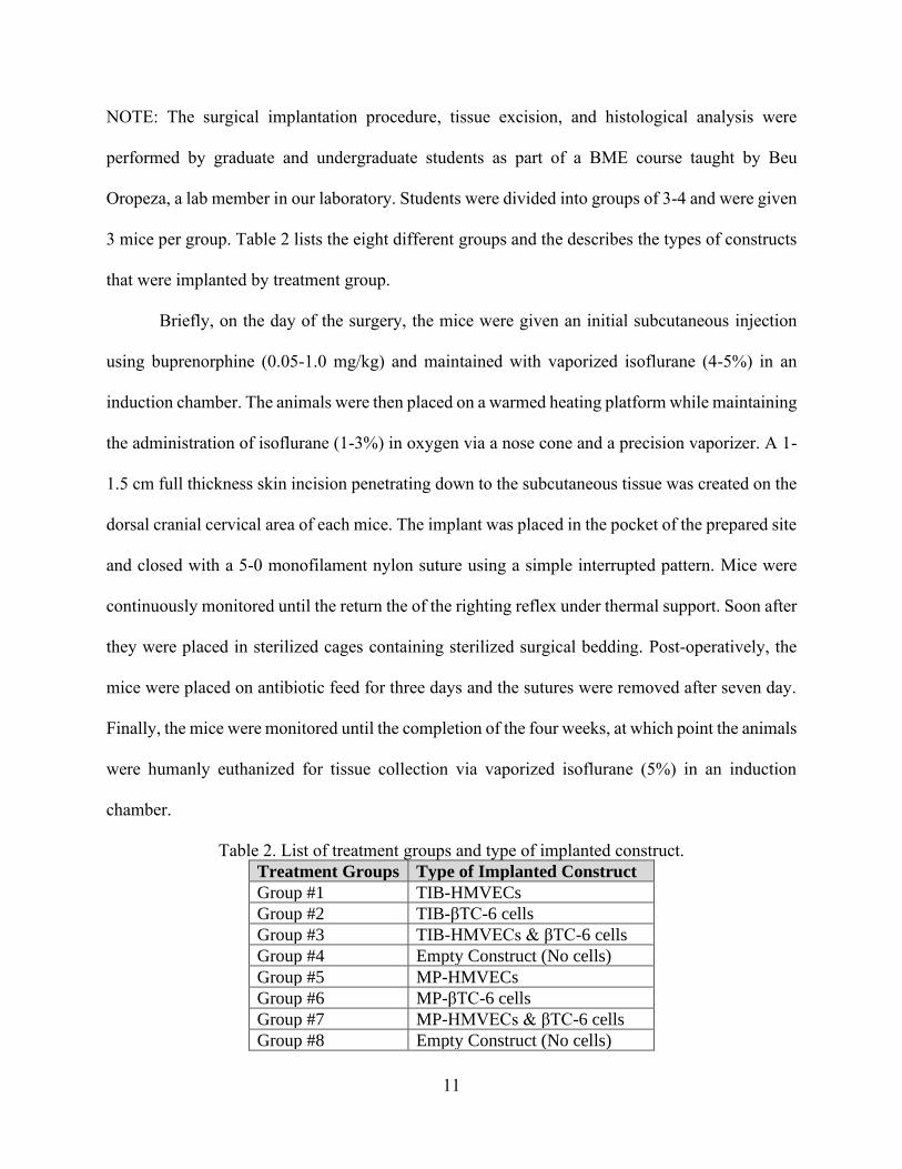
NOTE: The surgical implantation procedure, tissue excision, and histological analysis were
performed by graduate and undergraduate students as part of a BME course taught by Beu
Oropeza, a lab member in our laboratory. Students were divided into groups of 3-4 and were given
3 mice per group. Table 2 lists the eight different groups and the describes the types of constructs
that were implanted by treatment group.
Briefly, on the day of the surgery, the mice were given an initial subcutaneous injection
using buprenorphine (0.05-1.0 mg/kg) and maintained with vaporized isoflurane (4-5%) in an
induction chamber. The animals were then placed on a warmed heating platform while maintaining
the administration of isoflurane (1-3%) in oxygen via a nose cone and a precision vaporizer. A 1-
1.5 cm full thickness skin incision penetrating down to the subcutaneous tissue was created on the
dorsal cranial cervical area of each mice. The implant was placed in the pocket of the prepared site
and closed with a 5-0 monofilament nylon suture using a simple interrupted pattern. Mice were
continuously monitored until the return the of the righting reflex under thermal support. Soon after
they were placed in sterilized cages containing sterilized surgical bedding. Post-operatively, the
mice were placed on antibiotic feed for three days and the sutures were removed after seven day.
Finally, the mice were monitored until the completion of the four weeks, at which point the animals
were humanly euthanized for tissue collection via vaporized isoflurane (5%) in an induction
chamber.
Table 2. List of treatment groups and type of implanted construct.
Treatment Groups Type of Implanted Construct
Group #1 TIB-HMVECs
Group #2 TIB-βTC-6 cells
Group #3 TIB-HMVECs & βTC-6 cells
Group #4 Empty Construct (No cells)
Group #5 MP-HMVECs
Group #6 MP-βTC-6 cells
Group #7 MP-HMVECs & βTC-6 cells
Group #8 Empty Construct (No cells)
12
Histology
The harvested tissue samples were processed using a Spin Tissue Processor (Micro STP-
120, Thermo Scientific). The dehydration process was performed by immersing tissue samples in
different concentrations of ethanol (starting with 70%, 95%, 100%), followed by the clearing
process where samples were immersed in xylene two times and finally infiltrated in paraffin.
Paraffin embedded samples were then sectioned to 4 µm using a Sandon Finesse ® E/ME
microtome. All samples were deparaffinized in three xylene washes then rehydrated in decreasing
concentrations of ethanol (100%, 95%, 70%, 50%). Afterwards, tissue samples were stained with
hematoxylin and eosin (H&E) staining.
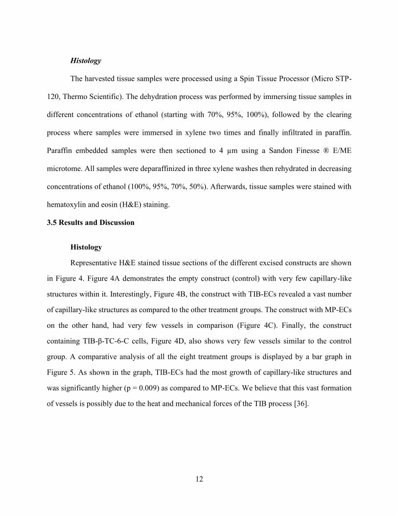
3.5 Results and Discussion
Histology
Representative H&E stained tissue sections of the different excised constructs are shown
in Figure 4. Figure 4A demonstrates the empty construct (control) with very few capillary-like
structures within it. Interestingly, Figure 4B, the construct with TIB-ECs revealed a vast number
of capillary-like structures as compared to the other treatment groups. The construct with MP-ECs
on the other hand, had very few vessels in comparison (Figure 4C). Finally, the construct
containing TIB-β-TC-6-C cells, Figure 4D, also shows very few vessels similar to the control
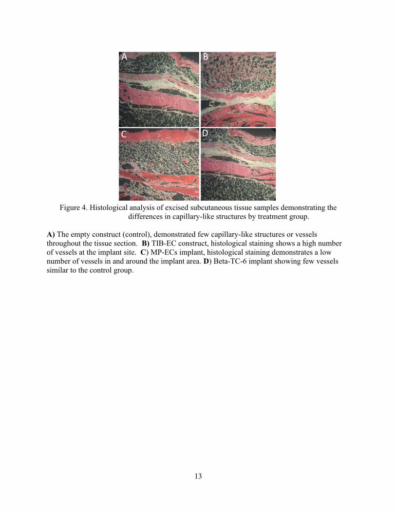
group. A comparative analysis of all the eight treatment groups is displayed by a bar graph in
Figure 5. As shown in the graph, TIB-ECs had the most growth of capillary-like structures and
was significantly higher (p = 0.009) as compared to MP-ECs. We believe that this vast formation
of vessels is possibly due to the heat and mechanical forces of the TIB process [36].
13
Figure 4. Histological analysis of excised subcutaneous tissue samples demonstrating the
differences in capillary-like structures by treatment group.
A) The empty construct (control), demonstrated few capillary-like structures or vessels
throughout the tissue section. B) TIB-EC construct, histological staining shows a high number
of vessels at the implant site. C) MP-ECs implant, histological staining demonstrates a low
number of vessels in and around the implant area. D) Beta-TC-6 implant showing few vessels
similar to the control group.
14
Figure 5. Bar graph demonstrating the mean number of vessels by implant type.
The bar graph demonstrates the mean number of vessels among the experimental groups while
comparing constructs containing TIB-ECs and MP-ECs. Constructs with TIB-ECs had a
significantly higher number of capillary-like structures as compared to constructs with MP-ECs at
the end of 4 weeks (p = 0.009). HMVEC-D = Dermal human microvascular endothelial cells, Beta-
TC-6 = pancreatic beta cells.
3.6 Conclusion
The histological results of our in vivo study showed a vast formation microvasculature
among the excised bioengineered constructs containing TIB-ECs. These preliminary data provide
compelling evidence that the TIB process is somehow inducing angiogenesis. Understanding the
mechanism of how the TIB process causes the observed angiogenic transformation will help to fill
a gap in knowledge about vascularization methods and potentially alter the wound dressing
paradigm.
15
Chapter 4: TIB Elicits Morphological Changes, Cytokine Expression, and Kinase
Activation In Vitro
4.1 Introduction
Bioprinters are advantageous in that they deposit cells and biomaterials in precise spatial
arrangements to enhance cell-cell communication, decrease cell migration time in populating a
tissue construct, and allow for the creation of artificial structures that closely resemble in vivo
tissues and organs [37]. The three main types of bioprinters are inkjet, microextrusion, and laser-
assisted printing. Comprehensive reviews on these bioprinters have been recently published
[38][39][40][41][42]. Most, if not all of the printing modalities involve heat generation, be it via laser,
heated nozzles, or friction as cells are forced through narrow orifices. Little is known, however,
about the direct effects that bioprinting inflicts on cells. In Chapter 2, we demonstrated that TIB-
ECs were recruited or otherwise involved in the formation of microvasculature in host animals
[35][43]. Cross-species grafting markers such as stains that specifically stain for human cells nuclei
were used to detect ECs in immunocompromised mice verified the connection of vascular
structures between graft and host, also known as anastomoses [44]. Additionally, histological
analysis of subcutaneous implants showed a significant higher number of capillary-like structures
among constructs with TIB-ECs as compared to the controls.
While it is important to conduct studies that characterize the interaction between host and
implanted bioprinted constructs, it is also important to understand the effects of the printing
process in order to improve the engineering design of these tissues or to improve printer designs.
Cells are fast adapting to their environment and they change intracellular structures, proliferation,
movement, and differentiation in response to external mechanical stimuli [37][45]. In addition,
changes in cell morphology due to mechanical injury may cause changes in downstream cellular
development [37][46]. We hypothesize that the heat and mechanical forces experienced by the cells
during the TIB process could have longer lasting effects on the cells ready to be transplanted. For
these reasons, we sought to investigate whether TIB-ECs are being activated to secrete cytokines
16
in their supernatant and/or to phosphorylate kinases intracellularly. The heat or mechanical forces
from the TIB process may cause HMVECs to release and activate specific angiogenic cytokines
and kinases resulting in the vast formation of microvascular networks we observed. It has been
demonstrated that HSP27 and other heat shock proteins regulate and induce angiogenesis,
especially tumor angiogenesis [47][48]. Eighteen HSP90 inhibitors have recently entered the clinic
as anti-cancer drugs [49], and HSP70 antagonists are explored as adjuvants [50]. However, in the
field of tissue engineering and particularly bioprinting, the induction of angiogenesis via HSPs
may be the desired response as vascularization and host integration of implants remains a
considerable challenge.
4.2 Materials and Methods
Cell Culture: Primary adult human dermal microvascular endothelial cells (HMVECs)
(Lonza) were cultured in EBM-2 media supplemented with an EGM-2 growth factor kit (Lonza)
containing 10 ml FBS; 0.2 ml hydrocortisone; 0.2 ml hFGF-B; 0.5 ml VEGF; 0.5 ml R3-IGF-1;
0.5 ml ascorbic acid; 0.5 ml hEGF; 0.5 ml GA-1000; and 0.5 ml heparin. Cell cultures were
maintained at 37 °C in a 5% CO2 environment. Cells were passaged at 80% confluency and were
used up to passage nine for the present experiments.
Bioink and Bioprinting Preparation: With the use of a thermal inkjet printer developed in
our laboratory [51], a corresponding bioink solution was made with 0.13 M CaCl2 in milli-Q water
and sterilized via syringe filtration giving a final osmolality concentration of 300 mOsm/kg.
HMVECs were trypsinized, counted, and mixed in the bioink solution to obtain a final
concentration of 2 x 10⁵ cells in 800 µl. One hundred microliters of the CaCl2/HMVECs solution
was loaded inside a modified printer cartridge and printed into the corresponding petri dish pre-
filled with 6 ml of complete EBM-2 media.
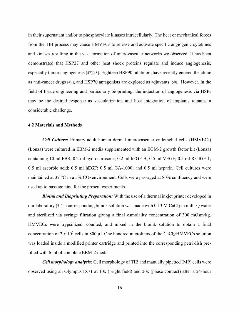
Cell morphology analysis: Cell morphology of TIB and manually pipetted (MP) cells were
observed using an Olympus IX71 at 10x (bright field) and 20x (phase contrast) after a 24-hour
17
incubation period. Images were taken with an Olympus DP72 digital camera with a 12.5
Megapixel resolution. Images were further processed on PowerPoint with a color tone of 6500 K,
100% color saturation, 0% brightness and contrast and a 50% sharpness.
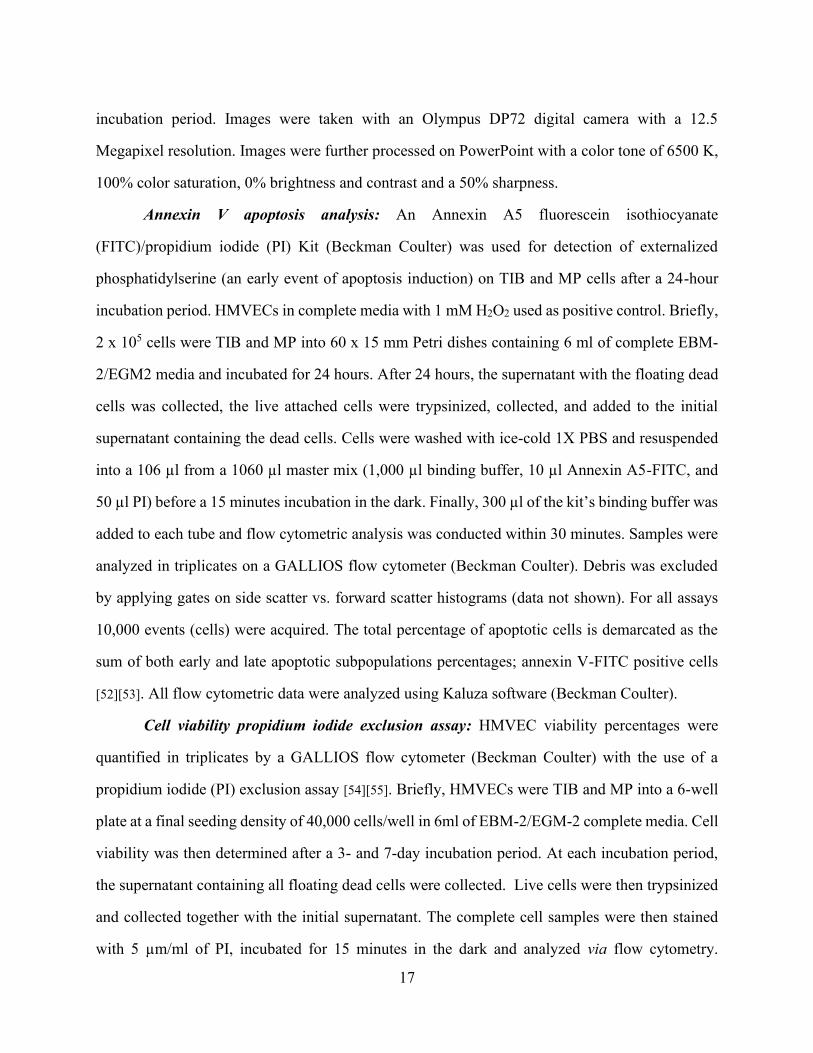
Annexin V apoptosis analysis: An Annexin A5 fluorescein isothiocyanate
(FITC)/propidium iodide (PI) Kit (Beckman Coulter) was used for detection of externalized
phosphatidylserine (an early event of apoptosis induction) on TIB and MP cells after a 24-hour
incubation period. HMVECs in complete media with 1 mM H2O2 used as positive control. Briefly,
2 x 10⁵ cells were TIB and MP into 60 x 15 mm Petri dishes containing 6 ml of complete EBM-
2/EGM2 media and incubated for 24 hours. After 24 hours, the supernatant with the floating dead
cells was collected, the live attached cells were trypsinized, collected, and added to the initial
supernatant containing the dead cells. Cells were washed with ice-cold 1X PBS and resuspended
into a 106 µl from a 1060 µl master mix (1,000 µl binding buffer, 10 µl Annexin A5-FITC, and
50 µl PI) before a 15 minutes incubation in the dark. Finally, 300 µl of the kit’s binding buffer was
added to each tube and flow cytometric analysis was conducted within 30 minutes. Samples were
analyzed in triplicates on a GALLIOS flow cytometer (Beckman Coulter). Debris was excluded
by applying gates on side scatter vs. forward scatter histograms (data not shown). For all assays
10,000 events (cells) were acquired. The total percentage of apoptotic cells is demarcated as the
sum of both early and late apoptotic subpopulations percentages; annexin V-FITC positive cells
[52][53]. All flow cytometric data were analyzed using Kaluza software (Beckman Coulter).
Cell viability propidium iodide exclusion assay: HMVEC viability percentages were
quantified in triplicates by a GALLIOS flow cytometer (Beckman Coulter) with the use of a
propidium iodide (PI) exclusion assay [54][55]. Briefly, HMVECs were TIB and MP into a 6-well
plate at a final seeding density of 40,000 cells/well in 6ml of EBM-2/EGM-2 complete media. Cell
viability was then determined after a 3- and 7-day incubation period. At each incubation period,
the supernatant containing all floating dead cells were collected. Live cells were then trypsinized
and collected together with the initial supernatant. The complete cell samples were then stained
with 5 µm/ml of PI, incubated for 15 minutes in the dark and analyzed via flow cytometry.
18
Unstained cells were used as controls to fine-tune the voltages for the FL1 and FL2 detectors, and
to modify the compensation values resulting in a gated ovoid shape of living cells. For all assays,
10,000 events (cells) were acquired per sample and analyzed using the Kaluza software (Beckman
Coulter).
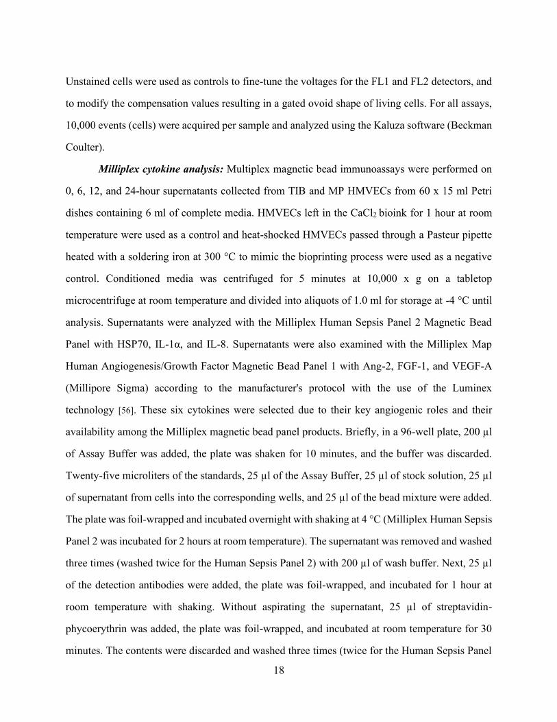
Milliplex cytokine analysis: Multiplex magnetic bead immunoassays were performed on
0, 6, 12, and 24-hour supernatants collected from TIB and MP HMVECs from 60 x 15 ml Petri
dishes containing 6 ml of complete media. HMVECs left in the CaCl2 bioink for 1 hour at room
temperature were used as a control and heat-shocked HMVECs passed through a Pasteur pipette
heated with a soldering iron at 300 °C to mimic the bioprinting process were used as a negative
control. Conditioned media was centrifuged for 5 minutes at 10,000 x g on a tabletop
microcentrifuge at room temperature and divided into aliquots of 1.0 ml for storage at -4 °C until
analysis. Supernatants were analyzed with the Milliplex Human Sepsis Panel 2 Magnetic Bead
Panel with HSP70, IL-1α, and IL-8. Supernatants were also examined with the Milliplex Map
Human Angiogenesis/Growth Factor Magnetic Bead Panel 1 with Ang-2, FGF-1, and VEGF-A
(Millipore Sigma) according to the manufacturer's protocol with the use of the Luminex
technology [56]. These six cytokines were selected due to their key angiogenic roles and their
availability among the Milliplex magnetic bead panel products. Briefly, in a 96-well plate, 200 µl
of Assay Buffer was added, the plate was shaken for 10 minutes, and the buffer was discarded.
Twenty-five microliters of the standards, 25 µl of the Assay Buffer, 25 µl of stock solution, 25 µl
of supernatant from cells into the corresponding wells, and 25 µl of the bead mixture were added.
The plate was foil-wrapped and incubated overnight with shaking at 4 °C (Milliplex Human Sepsis
Panel 2 was incubated for 2 hours at room temperature). The supernatant was removed and washed
three times (washed twice for the Human Sepsis Panel 2) with 200 µl of wash buffer. Next, 25 µl
of the detection antibodies were added, the plate was foil-wrapped, and incubated for 1 hour at
room temperature with shaking. Without aspirating the supernatant, 25 µl of streptavidin-
phycoerythrin was added, the plate was foil-wrapped, and incubated at room temperature for 30
minutes. The contents were discarded and washed three times (twice for the Human Sepsis Panel

19
2) with 200 µl of the wash buffer. Finally, 100 µl of the sheath fluid was added and the plate was
read on a MAGPIX Instrument. Median fluorescent intensity (MFI) data using a 5-parameter
curve-fitting method was used to measure analyte concentrations. The results from the samples
were analyzed using the Luminex xPONENT Software Version 4.2 Build 1324.
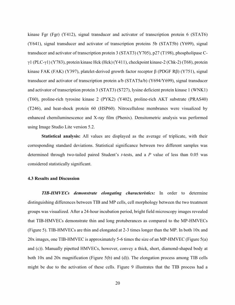
Proteome phospho-kinase array: HMVECs from three T-75 flasks at ~80% confluency
were TIB and manually (pipetted) seeded into a 100 x 15 mm Petri dish and incubated for 12 hours
at 37 °C, 5% CO2. Then, cells were washed with PBS, lysed in the presence of 1 mM
phenylmethylsulfonyl fluoride, 5 μg/ml aprotinin, 2 μg/ml leupeptin, and 1 μg/ml pepstatin A
proteases inhibitors and the resulting supernatant was clarified by centrifugation (14,000 x g, 5
minutes, 4 °C). Protein concentration was determined by the bicinchoninic acid method
(Pierce). Equal concentrations of protein were analyzed using the Proteome Profiler Human
Phospho-Kinase Array Kit (R&D Systems #ARY003B) according to the manufacturer’s protocol.
In this array, phosphorylation of 43 kinases and 2 related proteins were examined. Analytes and
phosphorylation sites included: p38α (T180/Y182), extracellular signal regulated kinase 1/2
(ERK1/2) (T202/Y204, T185/Y187), jun N-terminal kinase 1/2/3 (JNK 1/2/3) (T183/Y185,
T221/Y223), glycogen synthase kinase 3α/β (GSK-3α/β) (S21/S9), p53 (S392), epidermal growth
factor receptor (EGF R) (Y1086), mitogen- and stress-activated protein kinase 1/2 (MSK1/2)
(S376/S360), adenosine monophosphate-activated protein kinase α1 (AMPKα1) (T183), protein
kinase B 1/2/3 (AKT 1/2/3) (S473), protein kinase 1/2/3 AKT 1/2/3 (T308), p53 (S46), mammalian
target of rapamycin (mTOR) (S2448), cAMP response element-binding protein (CREB) (S133),
heat-shock protein 27 (HSP27) (S78/S82), adenosine monophosphate-activated protein kinase α2
(AMPKα2) (T172), β-Catenin, p70 S6 Kinase (T389), p53 (S15), protein kinase c-Jun (c-Jun)
(S63), protein kinase Src (Src) (Y419), protein kinase Lyn (Lyn) (Y397), protein kinase Lck (Lck)
(Y394), signal transducer and activator of transcription protein 2 (STAT2) (Y689), signal
transducer and activator of transcription protein 5a (STAT5a) (Y694), p70 S6 Kinase (T421/S424),
ribosomal s6 kinase 1/2/3 (RSK1/2/3) (S380/S386/S377), endothelial nitric oxide synthase
(eNOS) (S1177), protein kinase Fyn (Fyn) (Y420), protein kinase Yes (Yes) (Y426), protein
20
kinase Fgr (Fgr) (Y412), signal transducer and activator of transcription protein 6 (STAT6)
(Y641), signal transducer and activator of transcription proteins 5b (STAT5b) (Y699), signal
transducer and activator of transcription protein 3 (STAT3) (Y705), p27 (T198), phospholipase C-
γ1 (PLC-γ1) (Y783), protein kinase Hck (Hck) (Y411), checkpoint kinase-2 (Chk-2) (T68), protein
kinase FAK (FAK) (Y397), platelet-derived growth factor receptor β (PDGF Rβ) (Y751), signal
transducer and activator of transcription protein a/b (STAT5a/b) (Y694/Y699), signal transducer
and activator of transcription protein 3 (STAT3) (S727), lysine deficient protein kinase 1 (WNK1)
(T60), proline-rich tyrosine kinase 2 (PYK2) (Y402), proline-rich AKT substrate (PRAS40)
(T246), and heat-shock protein 60 (HSP60). Nitrocellulose membranes were visualized by
enhanced chemiluminescence and X-ray film (Phenix). Densitometric analysis was performed
using Image Studio Lite version 5.2.
Statistical analysis: All values are displayed as the average of triplicate, with their
corresponding standard deviations. Statistical significance between two different samples was
determined through two-tailed paired Student’s t-tests, and a P value of less than 0.05 was
considered statistically significant.
4.3 Results and Discussion
TIB-HMVECs demonstrate elongating characteristics: In order to determine
distinguishing differences between TIB and MP cells, cell morphology between the two treatment
groups was visualized. After a 24-hour incubation period, bright field microscopy images revealed
that TIB-HMVECs demonstrate thin and long protuberances as compared to the MP-HMVECs
(Figure 5). TIB-HMVECs are thin and elongated at 2-3 times longer than the MP. In both 10x and
20x images, one TIB-HMVEC is approximately 5-6 times the size of an MP-HMVEC (Figure 5(a)
and (c)). Manually pipetted HMVECs, however, convey a thick, short, diamond-shaped body at
both 10x and 20x magnification (Figure 5(b) and (d)). The elongation process among TIB cells
might be due to the activation of these cells. Figure 9 illustrates that the TIB process had a
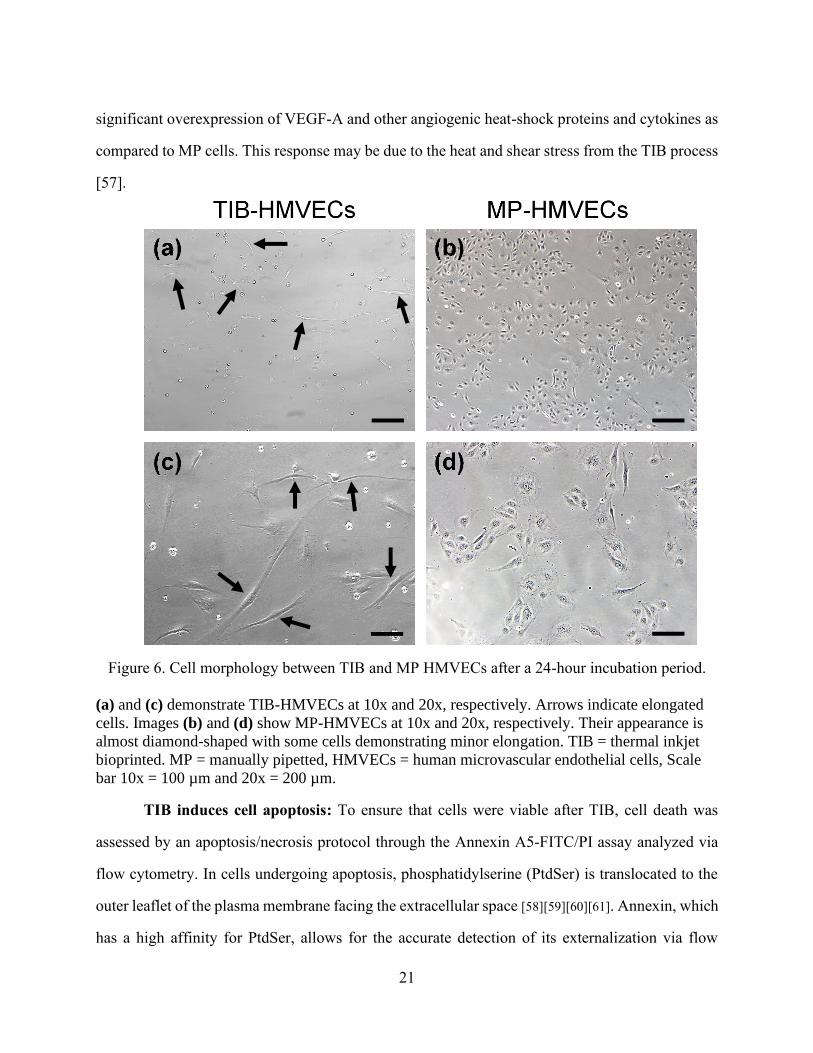
21
significant overexpression of VEGF-A and other angiogenic heat-shock proteins and cytokines as
compared to MP cells. This response may be due to the heat and shear stress from the TIB process
[57].
Figure 6. Cell morphology between TIB and MP HMVECs after a 24-hour incubation period.
(a) and (c) demonstrate TIB-HMVECs at 10x and 20x, respectively. Arrows indicate elongated
cells. Images (b) and (d) show MP-HMVECs at 10x and 20x, respectively. Their appearance is
almost diamond-shaped with some cells demonstrating minor elongation. TIB = thermal inkjet
bioprinted. MP = manually pipetted, HMVECs = human microvascular endothelial cells, Scale
bar 10x = 100 µm and 20x = 200 µm.
TIB induces cell apoptosis: To ensure that cells were viable after TIB, cell death was
assessed by an apoptosis/necrosis protocol through the Annexin A5-FITC/PI assay analyzed via
flow cytometry. In cells undergoing apoptosis, phosphatidylserine (PtdSer) is translocated to the
outer leaflet of the plasma membrane facing the extracellular space [58][59][60][61]. Annexin, which
has a high affinity for PtdSer, allows for the accurate detection of its externalization via flow
22
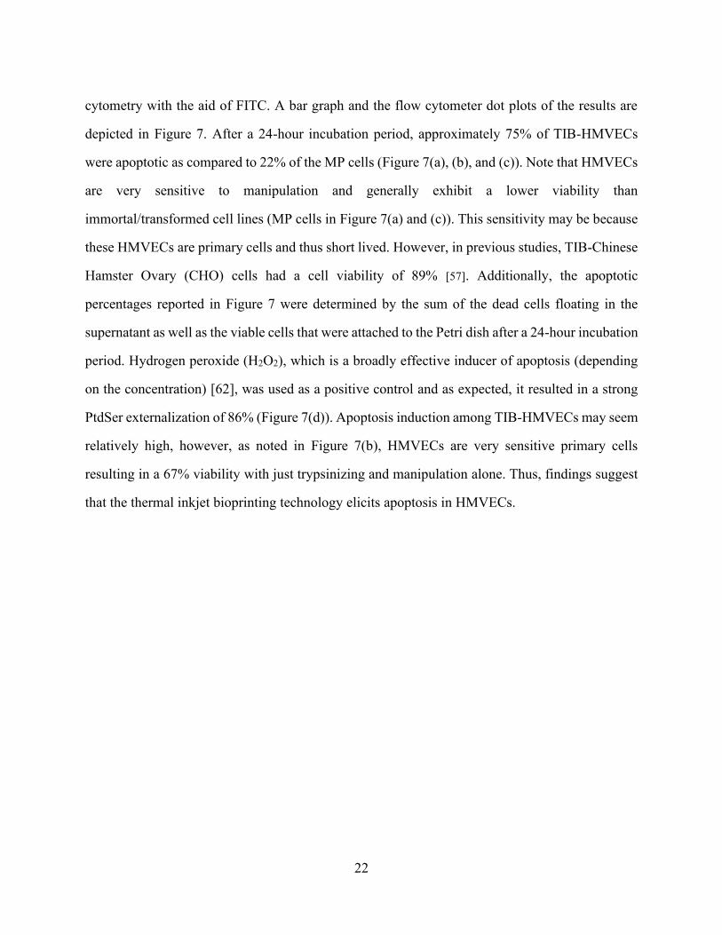
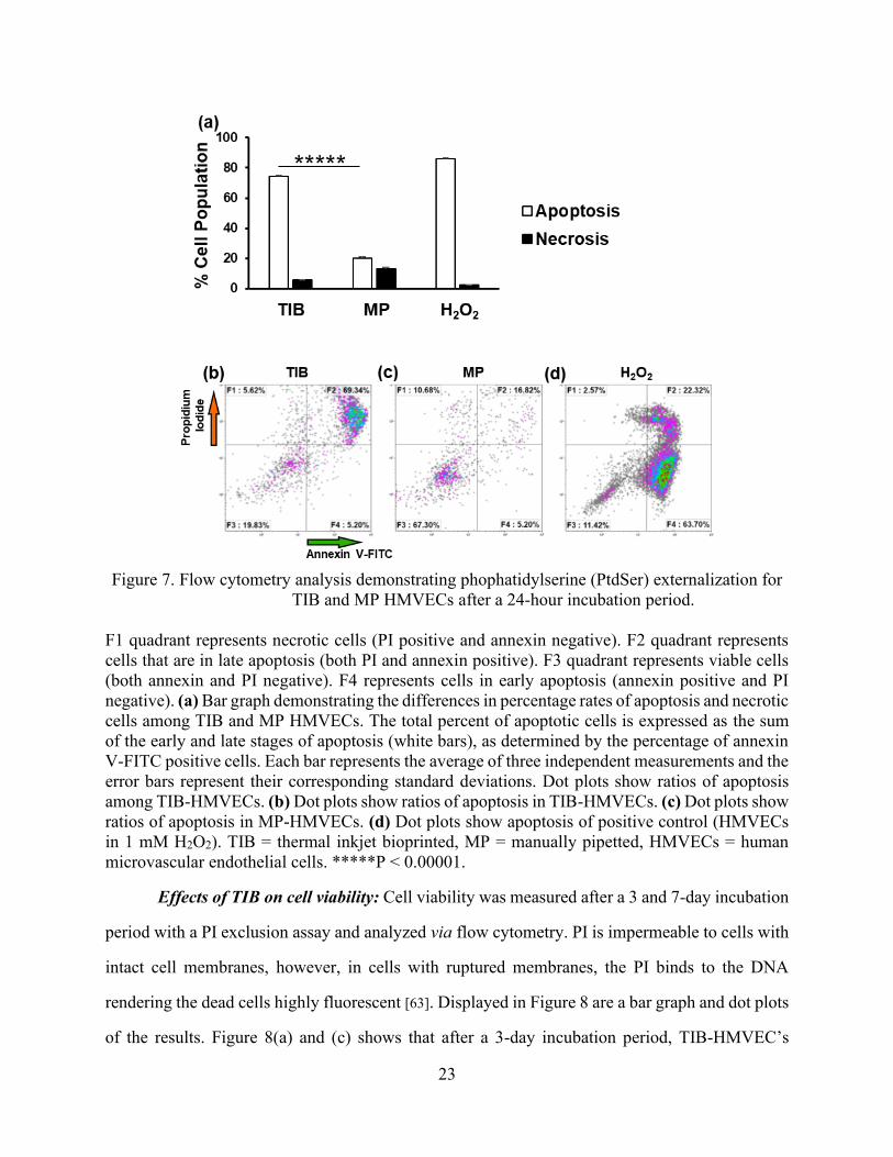
cytometry with the aid of FITC. A bar graph and the flow cytometer dot plots of the results are
depicted in Figure 7. After a 24-hour incubation period, approximately 75% of TIB-HMVECs
were apoptotic as compared to 22% of the MP cells (Figure 7(a), (b), and (c)). Note that HMVECs
are very sensitive to manipulation and generally exhibit a lower viability than
immortal/transformed cell lines (MP cells in Figure 7(a) and (c)). This sensitivity may be because
these HMVECs are primary cells and thus short lived. However, in previous studies, TIB-Chinese
Hamster Ovary (CHO) cells had a cell viability of 89% [57]. Additionally, the apoptotic
percentages reported in Figure 7 were determined by the sum of the dead cells floating in the
supernatant as well as the viable cells that were attached to the Petri dish after a 24-hour incubation
period. Hydrogen peroxide (H2O2), which is a broadly effective inducer of apoptosis (depending
on the concentration) [62], was used as a positive control and as expected, it resulted in a strong
PtdSer externalization of 86% (Figure 7(d)). Apoptosis induction among TIB-HMVECs may seem
relatively high, however, as noted in Figure 7(b), HMVECs are very sensitive primary cells
resulting in a 67% viability with just trypsinizing and manipulation alone. Thus, findings suggest
that the thermal inkjet bioprinting technology elicits apoptosis in HMVECs.
23
Figure 7. Flow cytometry analysis demonstrating phophatidylserine (PtdSer) externalization for
TIB and MP HMVECs after a 24-hour incubation period.
F1 quadrant represents necrotic cells (PI positive and annexin negative). F2 quadrant represents
cells that are in late apoptosis (both PI and annexin positive). F3 quadrant represents viable cells
(both annexin and PI negative). F4 represents cells in early apoptosis (annexin positive and PI
negative). (a) Bar graph demonstrating the differences in percentage rates of apoptosis and necrotic
cells among TIB and MP HMVECs. The total percent of apoptotic cells is expressed as the sum
of the early and late stages of apoptosis (white bars), as determined by the percentage of annexin
V-FITC positive cells. Each bar represents the average of three independent measurements and the
error bars represent their corresponding standard deviations. Dot plots show ratios of apoptosis
among TIB-HMVECs. (b) Dot plots show ratios of apoptosis in TIB-HMVECs. (c) Dot plots show
ratios of apoptosis in MP-HMVECs. (d) Dot plots show apoptosis of positive control (HMVECs
in 1 mM H2O2). TIB = thermal inkjet bioprinted, MP = manually pipetted, HMVECs = human
microvascular endothelial cells. *****P < 0.00001.
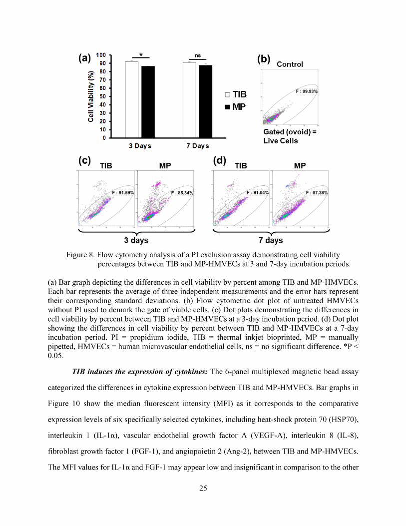
Effects of TIB on cell viability: Cell viability was measured after a 3 and 7-day incubation
period with a PI exclusion assay and analyzed via flow cytometry. PI is impermeable to cells with
intact cell membranes, however, in cells with ruptured membranes, the PI binds to the DNA
rendering the dead cells highly fluorescent [63]. Displayed in Figure 8 are a bar graph and dot plots
of the results. Figure 8(a) and (c) shows that after a 3-day incubation period, TIB-HMVEC’s
24
viability was significantly higher in comparison to MP-HMVECs (92% vs 86% cell viability,
respectively). After a 7-day incubation period, however, there was no significant difference in cell
viability between TIB and MP cells, Figure 8(a) and (d). Figure 8(b) is a dot plot of untreated
HMVECs without PI used as a control to determine the gate of viable cells. The reason we see a
higher cell viability among TIB-HMVECs might be due to increased secretion of VEGF-A, Figure
10(c). VEGF is a potent mitogen that regulates endothelial cell proliferation [64][65]. At 7 days,
these VEGF values might equilibrate to those similar to MP-HMVECs that we see in Figure 8(a)
and (d). Overall, the high cell viability shown by TIB-HMVECs after a one-week incubation
period demonstrates their potential incorporation into tissue engineering and regenerative
medicine applications.
25
Figure 8. Flow cytometry analysis of a PI exclusion assay demonstrating cell viability
percentages between TIB and MP-HMVECs at 3 and 7-day incubation periods.
(a) Bar graph depicting the differences in cell viability by percent among TIB and MP-HMVECs.
Each bar represents the average of three independent measurements and the error bars represent
their corresponding standard deviations. (b) Flow cytometric dot plot of untreated HMVECs
without PI used to demark the gate of viable cells. (c) Dot plots demonstrating the differences in
cell viability by percent between TIB and MP-HMVECs at a 3-day incubation period. (d) Dot plot
showing the differences in cell viability by percent between TIB and MP-HMVECs at a 7-day
incubation period. PI = propidium iodide, TIB = thermal inkjet bioprinted, MP = manually
pipetted, HMVECs = human microvascular endothelial cells, ns = no significant difference. *P <
0.05.
TIB induces the expression of cytokines: The 6-panel multiplexed magnetic bead assay
categorized the differences in cytokine expression between TIB and MP-HMVECs. Bar graphs in
Figure 10 show the median fluorescent intensity (MFI) as it corresponds to the comparative
expression levels of six specifically selected cytokines, including heat-shock protein 70 (HSP70),
interleukin 1 (IL-1α), vascular endothelial growth factor A (VEGF-A), interleukin 8 (IL-8),
fibroblast growth factor 1 (FGF-1), and angiopoietin 2 (Ang-2), between TIB and MP-HMVECs.
The MFI values for IL-1α and FGF-1 may appear low and insignificant in comparison to the other
26
four cytokines, however, when we took MFI readings of the EBM-2 media supplemented with an
EGM-2 growth factor kit (Lonza), we found similar trends in their MFI values: IL-8, 12.5; IL-1α,
38.5; FGF-1, 106.75; Ang-2, 163; HSP70, 306; and VEGF-A, 6623. As noted, media alone (devoid
of cells) contains great amounts of VEGF-A and low levels of IL-1α, IL-8, FGF-1, Ang-2, and
HSP70. Interestingly, the amount of HSP70 found in the EMB-2/EGM-2 complete media alone
was surpassed by over 7 times among TIB cells and was almost doubled in the MP cells. As a
result, HSP70 was significantly overexpressed among TIB-HMVECs as compared to the MP cells
(Figure 10(a)). This confirms that the TIB process is eliciting a heat shock response resulting in
the production of HSP70. Additionally, IL-1α increased over three times the amount in media
alone among TIB cells and increased slightly among MP cells with an overall significant
overexpression between both treatment groups (Figure 10(b)). This further confirms the cell-based
injury from TIB. IL-1α is a well-known inflammatory cytokine that is expressed in response to
trauma [66]. Moreover, IL-1α has been shown to promote the production of HSP70 family proteins
[67]. This also proves that pipetting cells manually causes minor cellular damage. The expression
of VEGF-A in Figure 10(c) was more than doubled among TIB cells in comparison to their EBM-
2/EGM-2 complete media values and may have been consumed by the MP cells. The observed
VEGF-A expression may not only be due to the shear stress from the printing process [68], but also
from the protective effects that HSP70 has on VEGF production. Kisher, A. et al., 2013,
demonstrated that in cells recovering from heat shock, VEGF mRNA degradation decreased
simultaneously as HSP70 expression levels increased [69]. Figure 10(d) shows the expression of
IL-8 which was almost 700 times fold for TIB and over 400 times fold for MP cells in comparison
to their complete media values. Furthermore, IL-8 was significantly overexpressed among TIB
cells in comparison to MP cells.
Interleukin-8, another pro-angiogenic cytokine [67], increases proliferation, migration, and
angiogenesis among ECs [70][71] by inducing VEGF secretion [72]. The expression of FGF-1
among TIB cells was similar to the value in the complete media, however, among MP cells, FGF-
1 was completely depleted (Figure 10(e)). Also, FGF-1 was overexpressed significantly in TIB
27
cells in comparison to MP cells. Finally, the expression of Ang-2 among TIB cells was seven times
the complete media values and over four times among the MP cells (Figure 10(f)). However, there
were no significant differences in expression between both treatment groups. It may be possible
that Ang-2 may have a synergistic effect with VEGF-A in our experiment [73][74]. It has been
demonstrated that Ang-1 is the key angiopoietin in EC migration, survival, and vessel development
and Ang-2 is its antagonist, however, along with VEGF, Ang-2 has proven to elicit angiogenic
effects [75].
Altogether, another possible explanation for the observed effects could be due to the
mechanical stretching of the cells as they are being bioprinted. As previously described in Figure
1, the mechanism behind the ejection of a bioink droplet is due to bursting or collapsing of bubbles
formed by a heating element inside the cartridge. As can be seen from Figure 2, the ejected drops
are oblong in shape with very long tails compared to their diameter. As the drops are ejected
through the air, the surface tension of the liquid tends to pull the tails back into the main drop.
Sometimes the tails are pinched off and small satellite drops are formed. It is possible that when
the cells are mixed within this liquid phase, their membranes will be stretched if they are on the
tail region of the drop. If the pinching occurs, the membrane will rupture, and cell will die. We
attribute the cell death seen in our results to this pinching off and satellite drop formation. Cells
that are largely in the bulk of the drop, may only experience some stretching of their membranes
due to the tail. One would expect many of these to survive but having somewhat leaky membranes
at first.
According to Cui X. et al., 2010 who performed cell damage evaluation on TIB Chinese
hamster ovary (CHO) cells, transient cell membrane pores were created among TIB-CHO cells.
By averaging the Stokes diameters of dextran molecules that penetrated CHO cell membranes,
they estimated that the average pore size was 105 Å at 25 minutes after being TIB, then 37 Å after
one hour, and eventually disappeared at two hours [57]. The formation of these pores might
possibly due to the stretching of their cell membranes. According to Pedrigi, R.M. et al., 2017,
ECs are extremely sensitive to mechanical stimulation and numerous studies have demonstrated
28
that shear stress and stretching have activated the expression of proliferation, migration, and
angiogenic mediators [76]. Similarly, Jufri, N.F. et al., 2015, found HSP70, VEGF, FGF, PDGF,
and Ang-2 expression due to mechanical stretching of ECs [77], further supporting our findings.
Thus, although these cells are exposed to a heating element that heats up to 300 °C, the actual
temperature of the bioink is approximately 4-10 °C degrees above ambient temperature [31][6] or
around 46°C [57] and lasts for about 10 µs before the cell is ejected [78], we firmly believe that
the reason for our observed results is due to the mechanical forces that causes EC stretching as
they are being bioprinted [79].
In a previous experiment, cytokine expression was assessed at 0, 6, 12, and 24-hour periods
and found that the most VEGF-A, IL-8 and FGF-1 expression occurred at 12 hours. For this reason,
the 12-hour incubation period was chosen for the present experiment. Figure 4 demonstrates the
differences of expression among the six afore mentioned cytokines consisting of TIB, MP, cells
left in bioink (Bioink), and heat shocked (HS) cells within a 24-hour time course period. To test if
the CaCl2 bioink had any effect on the expression of these cytokines, a control group consisting of
HMVECs left in the bioink for an hour at room temperature was examined. As expected, minimal
values of cytokine expression were lower than their EBM-2/EGM-2 complete media (Figure 9(a)-
(f)). Additionally, to examine if cell contents from ruptured HMVECs were releasing vast amounts
of the selected cytokines, a negative control consisting of heat shocked HMVECs ejected from a
Pasteur pipette heated with a solder iron to 300 ºC resulting in complete cell death was included.
Once again, minimal values of cytokine expression were detected in comparison to their EBM-
2/EGM-2 complete media (Figure 9(a)-(f)). This test proved that cytokine expression is an active
and not a passive process.
29
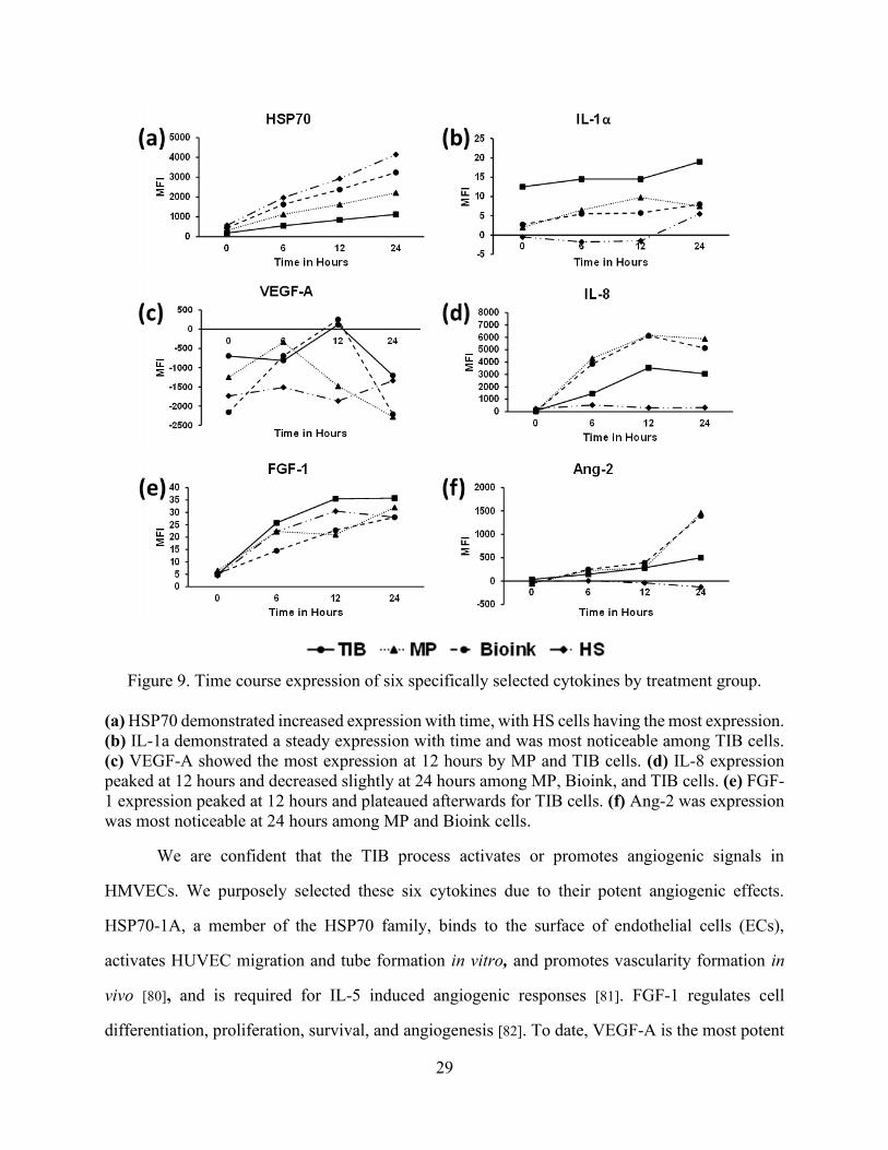
Figure 9. Time course expression of six specifically selected cytokines by treatment group.
(a) HSP70 demonstrated increased expression with time, with HS cells having the most expression.
(b) IL-1a demonstrated a steady expression with time and was most noticeable among TIB cells.
(c) VEGF-A showed the most expression at 12 hours by MP and TIB cells. (d) IL-8 expression
peaked at 12 hours and decreased slightly at 24 hours among MP, Bioink, and TIB cells. (e) FGF-
1 expression peaked at 12 hours and plateaued afterwards for TIB cells. (f) Ang-2 was expression
was most noticeable at 24 hours among MP and Bioink cells.
We are confident that the TIB process activates or promotes angiogenic signals in
HMVECs. We purposely selected these six cytokines due to their potent angiogenic effects.
HSP70-1A, a member of the HSP70 family, binds to the surface of endothelial cells (ECs),
activates HUVEC migration and tube formation in vitro, and promotes vascularity formation in
vivo [80], and is required for IL-5 induced angiogenic responses [81]. FGF-1 regulates cell
differentiation, proliferation, survival, and angiogenesis [82]. To date, VEGF-A is the most potent

30
pro-angiogenic cytokine. It promotes proliferation, tube formation, and sprouting of ECs [83][84].
Our TIB process did induce the expression of six potent angiogenic cytokines and these may be
the reason behind the differences in morphological differences between the TIB and MP-HMVECs
as depicted in Figure 6.
31
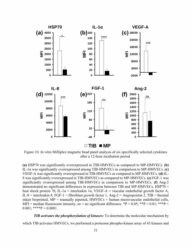
Figure 10. In vitro Milliplex magnetic bead panel analysis of six specifically selected cytokines
after a 12-hour incubation period.
(a) HSP70 was significantly overexpressed in TIB-HMVECs as compared to MP-HMVECs. (b)
IL-1α was significantly overexpressed among TIB-HMVECs in comparison to MP-HMVECs. (c)
VEGF-A was significantly overexpressed in TIB-HMVECs as compared to MP-HMVECs. (d) IL-
8 was significantly overexpressed in TIB-HMVECs as compared to MP-HMVECs. (e) FGF-1 was
significantly overexpressed among TIB-HMVECs in comparison to MP-HMVECs. (f) Ang-2
demonstrated no significant differences in expression between TIB and MP-HMVECs. HSP70 =
heat shock protein 70, IL-1α = interleukin 1α, VEGF-A = vascular endothelial growth factor A,
IL-8 = interleukin 8, FGF-1 = fibroblast growth factor 1, Ang-2 = Angiopoietin 2, TIB = thermal
inkjet bioprinted, MP = manually pipetted, HMVECs = human microvascular endothelial cells,
MFI = median fluorescent intensity, ns = no significant difference. *P < 0.05; **P < 0.01; ***P <
0.001; ****P < 0.0001.
TIB activates the phosphorylation of kinases: To determine the molecular mechanism by
which TIB activates HMVECs, we performed a proteome phospho-kinase array of 43 kinases and
0
20
40
60
80
100
120
140
160
MF
I
IL-1α
0
500
1000
1500
2000
2500
3000
3500
4000
MF
I
HSP70
-2000
3000
8000
13000
18000
23000
28000
MF
I
VEGF-A
0
2000
4000
6000
8000
10000
12000
MF
I
IL-8
-40
10
60
110
160
210
MF
IFGF-1
0
200
400
600
800
1000
1200
1400
1600
1800
2000
MF
I
Ang-2
(a)
(f) (e) (d)
(c) (b)
0
500
1000
1500
2000
2500
3000
3500
4000M
FI
HSP70
TIB MP
* ****
***
*** **
ns
32
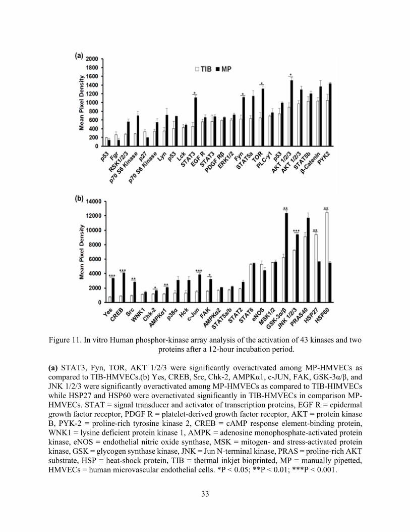
two proteins. The bar graph depicted in Figure 11(a) demonstrates that STAT3, Fyn, mTOR, and
AKT1/2/3 were significantly under activated in TIB cells as compared to MP cells. Similarly, the
bar graph in Figure 11(b), shows that Yes, CREB, Src, Chk2, AMPKα1, c-Jun, FAK, GSK-3α/β,
JNK1/2/3 were under activated significantly in TIB-ECs as compared to the MP cells.
Grouped together, the non-receptor tyrosine kinases Fyn, Yes, Src, and FAK are involved
in survival, proliferation, migration, and angiogenesis [85][86][87]. Similarly, the serine/threonine
kinases, AKT1/2/3, mTOR, GSK-3α/β, and JNK1/2/3, are also involved in the regulation of
apoptosis, survival, proliferation, migration, angiogenesis [88][89][90][91], cellular homeostasis
(AMPKα1/2) [92], and a cell division checkpoint (Chk2) [93]. Finally, the CREB, c-JUN, and
STAT3 transcription factors are also involved in survival, proliferation, and angiogenesis
[94][95][87]. The grouping of each type of kinase, protein, transcription factor, and heat shock
protein are listed in Table 3 along with their individual function. Additionally, Figure 12 depicts
an illustration detailing where the kinases and proteins play a role among the different signaling
pathways. Altogether, our findings suggest that TIB-ECs were not proliferating as compared to
the MP cells. Possibly, TIB-ECs have an entered a nonproliferative state due to a state of shock
after the harsh TIB process which resulted in a 25% viability as seen in Figure 7. Perhaps growth-
arrest genes were activated due to the mechanical stretching stress induced by the TIB process.
This is further supported by Chien, S., (2007) who confirmed that ECs under the effects of shear
stress demonstrated a nonproliferaive state as compared to cells without shear stress in vitro [96].
33
Figure 11. In vitro Human phosphor-kinase array analysis of the activation of 43 kinases and two
proteins after a 12-hour incubation period.
(a) STAT3, Fyn, TOR, AKT 1/2/3 were significantly overactivated among MP-HMVECs as
compared to TIB-HMVECs.(b) Yes, CREB, Src, Chk-2, AMPKα1, c-JUN, FAK, GSK-3α/β, and
JNK 1/2/3 were significantly overactivated among MP-HMVECs as compared to TIB-HIMVECs
while HSP27 and HSP60 were overactivated significantly in TIB-HMVECs in comparison MP-
HMVECs. STAT = signal transducer and activator of transcription proteins, EGF R = epidermal
growth factor receptor, PDGF R = platelet-derived growth factor receptor, AKT = protein kinase
B, PYK-2 = proline-rich tyrosine kinase 2, CREB = cAMP response element-binding protein,
WNK1 = lysine deficient protein kinase 1, AMPK = adenosine monophosphate-activated protein
kinase, eNOS = endothelial nitric oxide synthase, MSK = mitogen- and stress-activated protein
kinase, GSK = glycogen synthase kinase, JNK = Jun N-terminal kinase, PRAS = proline-rich AKT
substrate, HSP = heat-shock protein, TIB = thermal inkjet bioprinted, MP = manually pipetted,
HMVECs = human microvascular endothelial cells. *P < 0.05; **P < 0.01; ***P < 0.001.
34
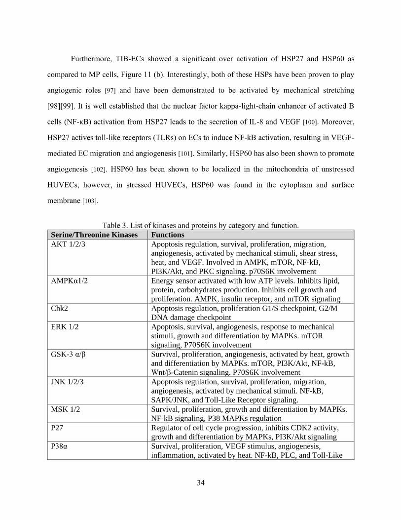
Furthermore, TIB-ECs showed a significant over activation of HSP27 and HSP60 as
compared to MP cells, Figure 11 (b). Interestingly, both of these HSPs have been proven to play
angiogenic roles [97] and have been demonstrated to be activated by mechanical stretching
[98][99]. It is well established that the nuclear factor kappa-light-chain enhancer of activated B
cells (NF-κB) activation from HSP27 leads to the secretion of IL-8 and VEGF [100]. Moreover,
HSP27 actives toll-like receptors (TLRs) on ECs to induce NF-kB activation, resulting in VEGF-
mediated EC migration and angiogenesis [101]. Similarly, HSP60 has also been shown to promote
angiogenesis [102]. HSP60 has been shown to be localized in the mitochondria of unstressed
HUVECs, however, in stressed HUVECs, HSP60 was found in the cytoplasm and surface
membrane [103].
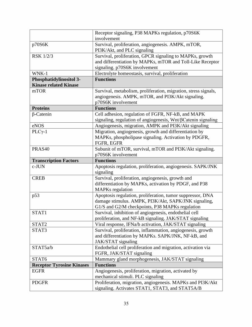
Table 3. List of kinases and proteins by category and function.
Serine/Threonine Kinases Functions
AKT 1/2/3 Apoptosis regulation, survival, proliferation, migration,
angiogenesis, activated by mechanical stimuli, shear stress,
heat, and VEGF. Involved in AMPK, mTOR, NF-kB,
PI3K/Akt, and PKC signaling. p70S6K involvement
AMPKα1/2 Energy sensor activated with low ATP levels. Inhibits lipid,
protein, carbohydrates production. Inhibits cell growth and
proliferation. AMPK, insulin receptor, and mTOR signaling
Chk2 Apoptosis regulation, proliferation G1/S checkpoint, G2/M
DNA damage checkpoint
ERK 1/2 Apoptosis, survival, angiogenesis, response to mechanical
stimuli, growth and differentiation by MAPKs. mTOR
signaling, P70S6K involvement
GSK-3 α/β Survival, proliferation, angiogenesis, activated by heat, growth
and differentiation by MAPKs. mTOR, PI3K/Akt, NF-kB,
Wnt/β-Catenin signaling. P70S6K involvement
JNK 1/2/3 Apoptosis regulation, survival, proliferation, migration,
angiogenesis, activated by mechanical stimuli. NF-kB,
SAPK/JNK, and Toll-Like Receptor signaling.
MSK 1/2 Survival, proliferation, growth and differentiation by MAPKs.
NF-kB signaling, P38 MAPKs regulation
P27 Regulator of cell cycle progression, inhibits CDK2 activity,
growth and differentiation by MAPKs, PI3K/Akt signaling
P38α Survival, proliferation, VEGF stimulus, angiogenesis,
inflammation, activated by heat. NF-kB, PLC, and Toll-Like
35
Receptor signaling, P38 MAPKs regulation, p70S6K
involvement
p70S6K Survival, proliferation, angiogenesis. AMPK, mTOR,
PI3K/Akt, and PLC signaling
RSK 1/2/3 Survival, proliferation, GPCR signaling to MAPKs, growth
and differentiation by MAPKs, mTOR and Toll-Like Receptor
signaling. p70S6K involvement
WNK-1 Electrolyte homeostasis, survival, proliferation
Phosphatidylinositol 3-
Kinase related Kinase
Functions
mTOR Survival, metabolism, proliferation, migration, stress signals,
angiogenesis. AMPK, mTOR, and PI3K/Akt signaling.
p70S6K involvement
Proteins Functions
β-Catenin Cell adhesion, regulation of FGFR, NF-kB, and MAPK
signaling, regulation of angiogenesis, Wnt/βCatenin signaling
eNOS Angiogenesis, migration, AMPK and PI3K/Akt signaling
PLCγ-1 Migration, angiogenesis, growth and differentiation by
MAPKs, phospholipase signaling. Activation by PDGFR,
FGFR, EGFR
PRAS40 Subunit of mTOR, survival, mTOR and PI3K/Akt signaling.
p70S6K involvement
Transcription Factors Functions
c-JUN Apoptosis regulation, proliferation, angiogenesis. SAPK/JNK
signaling
CREB Survival, proliferation, angiogenesis, growth and
differentiation by MAPKs, activation by PDGF, and P38
MAPKs regulation
p53 Apoptosis regulation, proliferation, tumor suppressor, DNA
damage stimulus. AMPK, PI3K/Akt, SAPK/JNK signaling,
G1/S and G2/M checkpoints, P38 MAPKs regulation
STAT1 Survival, inhibition of angiogenesis, endothelial cell
proliferation, and NF-kB signaling. JAK/STAT signaling
STAT2 Viral response, IFNa/b activation, JAK/STAT signaling
STAT3 Survival, proliferation, inflammation, angiogenesis, growth
and differentiation by MAPKs. SAPK/JNK, NF-kB, and
JAK/STAT signaling
STAT5a/b Endothelial cell proliferation and migration, activation via
FGFR, JAK/STAT signaling
STAT6 Mammary gland morphogenesis, JAK/STAT signaling
Receptor Tyrosine Kinases Functions
EGFR Angiogenesis, proliferation, migration, activated by
mechanical stimuli. PLC signaling
PDGFR Proliferation, migration, angiogenesis. MAPKs and PI3K/Akt
signaling. Activates STAT1, STAT3, and STAT5A/B
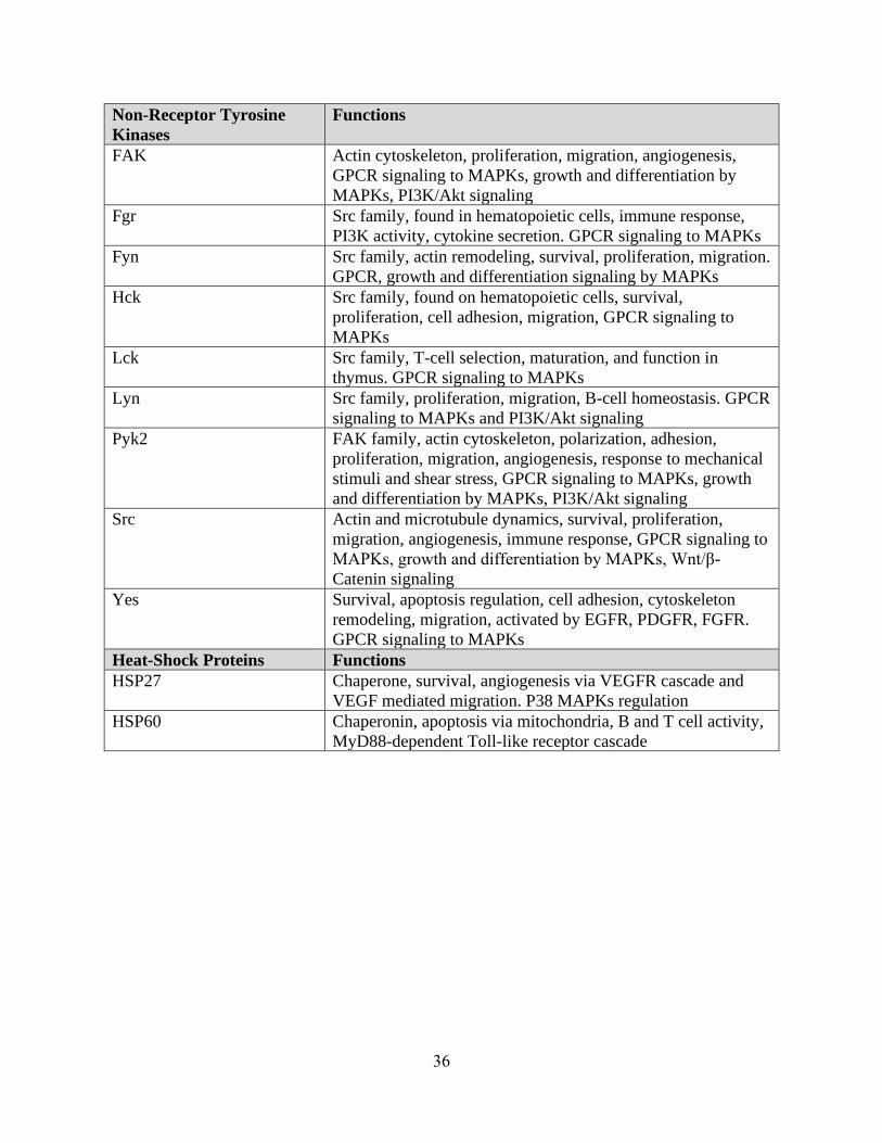
36
Non-Receptor Tyrosine
Kinases
Functions
FAK Actin cytoskeleton, proliferation, migration, angiogenesis,
GPCR signaling to MAPKs, growth and differentiation by
MAPKs, PI3K/Akt signaling
Fgr Src family, found in hematopoietic cells, immune response,
PI3K activity, cytokine secretion. GPCR signaling to MAPKs
Fyn Src family, actin remodeling, survival, proliferation, migration.
GPCR, growth and differentiation signaling by MAPKs
Hck Src family, found on hematopoietic cells, survival,
proliferation, cell adhesion, migration, GPCR signaling to
MAPKs
Lck Src family, T-cell selection, maturation, and function in
thymus. GPCR signaling to MAPKs
Lyn Src family, proliferation, migration, B-cell homeostasis. GPCR
signaling to MAPKs and PI3K/Akt signaling
Pyk2 FAK family, actin cytoskeleton, polarization, adhesion,
proliferation, migration, angiogenesis, response to mechanical
stimuli and shear stress, GPCR signaling to MAPKs, growth
and differentiation by MAPKs, PI3K/Akt signaling
Src Actin and microtubule dynamics, survival, proliferation,
migration, angiogenesis, immune response, GPCR signaling to
MAPKs, growth and differentiation by MAPKs, Wnt/β-
Catenin signaling
Yes Survival, apoptosis regulation, cell adhesion, cytoskeleton
remodeling, migration, activated by EGFR, PDGFR, FGFR.
GPCR signaling to MAPKs
Heat-Shock Proteins Functions
HSP27 Chaperone, survival, angiogenesis via VEGFR cascade and
VEGF mediated migration. P38 MAPKs regulation
HSP60 Chaperonin, apoptosis via mitochondria, B and T cell activity,
MyD88-dependent Toll-like receptor cascade
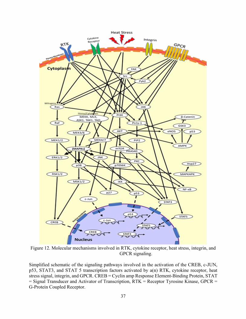
37
Figure 12. Molecular mechanisms involved in RTK, cytokine receptor, heat stress, integrin, and
GPCR signaling.
Simplified schematic of the signaling pathways involved in the activation of the CREB, c-JUN,
p53, STAT3, and STAT 5 transcription factors activated by a(n) RTK, cytokine receptor, heat
stress signal, integrin, and GPCR. CREB = Cyclin amp Response Element-Binding Protein, STAT
= Signal Transducer and Activator of Transcription, RTK = Receptor Tyrosine Kinase, GPCR =
G-Protein Coupled Receptor.
38
The effects observed in our study may not only be specific to thermal inkjet printers but
might also occur in laser-based direct-write printing, electrospinning techniques for cell patterning
and possibly extrusion-based systems when small diameter nozzles are used. Laser-based direct-
write printing technologies include laser-induced forward transfer (LIFT), absorbing film-assisted
laser-induced forward transfer (AFA-LIFT), biological laser processing (BioLP), matrix-assisted
pulsed laser evaporation direct writing (MAPLE DW), and laser-guided direct writing (LG DW)
[104]. Cell electrospinning consists of electrospun cell-laden threads within a specific
biosuspension [105]. In laser-based direct-write cell patterning, the laser heats the laser absorption
layer, causing the formation of a bubble which collapses, resulting in the specified pattern. Cell
viability regarding cell acceleration and deceleration as the cell droplet forms and lands on the
substrate is discussed. However, there is no mention of the heat stress induced by the laser [104].
Regarding cell electrospinning, cell viability was found to be 25%, similar to other findings [106].
Among solid freeform fabrication-based direct cell writing, dispensing pressure and nozzle size
was found to induce mechanical cell membrane damage [37].
As we have documented, all these different cell manipulations or patterning techniques for
the purposes of biofabricating living systems induce some form of stress or significant cell death.
For this reason, we ought to characterize the expression and activation of various cytokines and
kinases among other biofabrication techniques to see if we are indeed creating the desired effects
upon implantation. There is also the possibility that the bioprinting process changes the
intracellular structures of the cells, leading to the physiological change of cells and possibly
inducing cell transformation or uncontrolled cell growth. In this case, the focus towards new
biofabricating modalities should involve designing novel cell manipulation techniques that
promote less heat and mechanical induced cellular trauma. Enlarging nozzle sizes or cell
encapsulating methods could also be implemented in order to minimize the downstream damaging
effects from the bioprinting process.
39
4.4 Conclusion
In conclusion, we have demonstrated that TIB-ECs significantly overexpressed five
angiogenic cytokines and significantly over activated two HSPs that also play an angiogenic role.
Moreover, due to these observations and our supporting evidence, we now firmly believe that as
ECs are being ejected from the nozzles, they are being stretched out among the tails of the droplets.
In doing so, they become activated by a mechanical stress rather than a heat-stress as we previously
hypothesized. It is hoped that with further progress, our TIB technology could be used as a new
vascularization strategy since the formation of anastomosis and functional vascular networks
remains a tremendous challenge in the field of tissue engineering and regenerative medicine [107].
40
Chapter 5: Conclusions, Limitations, and Future Work
Conclusions
In conclusion, we have demonstrated that constructs containing TIB-ECs offers an
alternative method to inducing microvascular networks in vivo. Our in vitro data also supports our
findings as they translate in vivo. In a recent separate in vivo study, performed on humanized mice,
while following the same protocol exhibited similar results to those we obtained (manuscript in
progress). Similarly, our in vitro observations also uphold our hypothesis that ECs are exposed to
mechanical stress inside the reservoir of the cartridge resulting in the stretching of these cells as
they are being bioprinted. The ability to create vast capillary networks, coupled with the fixed
printing parameters of our TIB technology (i.e. heat, pressure, nozzle size, droplet size, and
velocity) allows for versatile and repeatable means to create these constructs.
Limitations
A major limitation of this work mainly rested on the clogging of the modified printer
cartridges during the bioprinting process. We believe that the channels leading to the nozzles
become blocked by cellular sedimentation as well as cellular debris from the harsh heat and
mechanical forces associated with bioprinting. As a result, multiple to cartridges are needed to
carry out experiments, especially those that require a vast number of cells, such as the proteome
phosphorylation kinase array previously presented. Additionally, even though desktop inkjet
printers are still widely accessible, the original ink cartridges are difficult to acquire. The original
cartridges have become obsolete and are no longer in production. Among the original cartridges
we managed to purchase, we have observed corrosion of the outer electrical components due to
the ink that leaked during years of storage. Printing using replica cartridges was also limited as
they ejected few to no cells following the initial print. Efforts to unclog the few cartridges on hand
41
include the use of sonication, forced pressure ejection (using a syringe), and boiling as well as
acetic acid, EDTA, and trypsin solutions. These methods have demonstrated some efficacy and
provide temporary use, but ultimately, they stop printing. Presently, the issue of cartridge
restoration continues to limit its bioprinting capacity.
Future Work
Future in vitro work with appropriate controls for mechanical stress or possibly printing
with the cartridge submerged within media to control for cellular stretching are recommended.
Also, in vivo work with diabetic or impaired wound healing models such as a diabetic foot ulcer
along with the afore mentioned controls are also suggested. Additionally, a comparative study
among different types of commercially available ECs and/or TIB modalities are also
recommended. Looking ahead, bioengineered constructs using our TIB technology may find
potential applications in organ on a chip, drug testing, and autonomic healing applications.
42
References
[1] L. Yazdanpanah, M. Nasiri, and S. Adarvishi, “Literature review on the management of
diabetic foot ulcer.,” World journal of diabetes, vol. 6, no. 1. pp. 37–53, 2015.
[2] W. Clayton and T. A. Elasy, “A Review of the Pathophysiology, Classification, and
Treatment of Foot Ulcers in Diabetic Patients,” Clin. Diabetes, vol. 27, no. 2, pp. 52–58,
2009.
[3] T. Emanuelli, A. Burgeiro, and E. Carvalho, “Effects of insulin on the skin: possible
healing benefits for diabetic foot ulcers,” Archives of Dermatological Research, vol. 308,
no. 10. pp. 677–694, 2016.
[4] T. Dinh, F. Tecilazich, A. Kafanas, J. Doupis, C. Gnardellis, E. Leal, A. Tellechea, L.
Pradhan, T. E. Lyons, J. M. Giurini, and A. Veves, “Mechanisms involved in the
development and healing of diabetic foot ulceration,” Diabetes, vol. 61, no. 11, pp. 2937–
2947, 2012.
[5] W. D. Aumiller and H. A. Dollahite, “Pathogenesis and management of diabetic foot
ulcers,” J. Am. Acad. Physician Assist., vol. 28, no. 5, pp. 28–34, 2015.
[6] X. Cui, T. Boland, D. D. D’Lima, and M. K. Lotz, “Thermal inkjet printing in tissue
engineering and regenerative medicine.,” Recent Pat. Drug Deliv. Formul., vol. 6, no. 2,
pp. 149–55, 2012.
[7] F. J. Alvaro-afonso, “Advances in dermoepidermal skin substitutes for diabetic foot ulcers
Advances in Dermoepidermal Skin Substitutes for Diabetic Foot Ulcers,” no. April, 2019.
[8] G. Messenger, R. Masoetsa, and I. Hussain, “A Narrative Review of the Benefits and
Risks of Total Contact Casts in the Management of Diabetic Foot Ulcers,” J. Am. Coll.
Clin. Wound Spec., vol. 9, no. 1–3, pp. 19–23, 2017.
43
[9] L. E. Gasca-lozano, S. Lucano-landeros, H. Ruiz-mercado, A. Salazar-montes, A.
Sandoval-rodríguez, J. Garcia-bañuelos, A. Santos-garcia, J. R. Davila-rodriguez, J.
Navarro-partida, H. Bojórquez-sepúlveda, J. Castañeda-gomez, J. Domínguez-rosales, M.
A. Ruiz-arcos, M. G. Sánchez-parada, and J. Armendariz-borunda, “Clinical Study
Pirfenidone Accelerates Wound Healing in Chronic Diabetic Foot Ulcers : A Randomized
, Double-Blind Controlled Trial,” vol. 2017, 2017.
[10] M. Hoffmann, P. Kujath, A. Flemming, M. Proß, N. Begum, M. Zimmermann, T. Keck,
M. Kleemann, and E. Schloericke, “Survival of diabetes patients with major amputation is
comparable to malignant disease,” Diabetes Vasc. Dis. Res., vol. 12, no. 4, pp. 265–271,
2015.
[11] “Activity Patterns of Patients With Diabetic Foot Ulceration,” vol. 26, no. 9, 2003.
[12] C. Care, “Use of Pressure Offloading Devices in,” vol. 31, no. 11, 2008.
[13] T. Y. Ryu, J. Park, and P. E. Scherer, “Hyperglycemia as a risk factor for cancer
progression,” Diabetes and Metabolism Journal. 2014.
[14] C. Library, “Treatment of the diabetic foot by offloading: a systematic review.”
[15] M. Bartoli, X. Gu, N. T. Tsai, R. C. Venema, S. E. Brooks, M. B. Marrero, and R. B.
Caldwell, “Vascular endothelial growth factor activates STAT proteins in aortic
endothelial cells,” J. Biol. Chem., vol. 275, no. 43, pp. 33189–33192, 2000.
[16] R. T. Crews, B. Shen, L. Campbell, P. J. Lamont, A. J. M. Boulton, M. Peyrot, R. S.
Kirsner, L. Vileikyte, C. Care, and E. Nutrition, “Role and Determinants of Adherence to
Off-loading in Diabetic Foot Ulcer Healing : A Prospective Investigation,” vol. 39, no.
August, pp. 1371–1377, 2016.
[17] W. Lafayette, “A comparative analysis of skin substitutes used in the management of

44
diabetic foot ulcers,” 2014.
[18] S. Tb, P. Ppc, and U. Dt, “Skin grafting and tissue replacement for treating foot ulcers in
people with diabetes ( Review ),” no. 2, 2017.
[19] K. E. Johnson and T. A. Wilgus, “Vascular Endothelial Growth Factor and Angiogenesis
in the Regulation of Cutaneous Wound Repair,” vol. 3, no. 10, pp. 647–661, 2014.
[20] T. M. Honnegowda, P. Kumar, E. Govindarama, P. Udupa, S. Kumar, U. Kumar, and P.
Rao, “Role of angiogenesis and angiogenic factors in acute and chronic wound healing,”
2015.
[21] P. Bao, A. Kodra, M. Tomic-canic, D. Ph, M. S. Golinko, H. P. Ehrlich, D. Ph, and H.
Brem, “The Role of Vascular Endothelial Growth Factor in Wound Healing,” YJSRE, vol.
153, no. 2, pp. 347–358, 2009.
[22] Z. Chen, S. Fu, Z. Wu, J. Chen, Y. Huang, Y. Wang, and M. Fu, “Clinica Chimica Acta
Relationship between plasma angiogenic growth factors and diabetic foot ulcers,” Clin.
Chim. Acta, vol. 482, no. January, pp. 95–100, 2018.
[23] B. Salvador, A. Arranz, S. Francisco, L. Córdoba, C. Punzón, M. Ángel, and M. Fresno,
“Modulation of endothelial function by Toll like receptors,” Pharmacol. Res., vol. 108,
pp. 46–56, 2016.
[24] S. Saberianpour, M. Heidarzadeh, M. H. Geranmayeh, and H. Hosseinkhani, “Tissue
engineering strategies for the induction of angiogenesis using biomaterials,” vol. 4, pp. 1–
15, 2018.
[25] M. Lovett, D. Ph, K. Lee, D. Ph, A. Edwards, D. Ph, D. L. Kaplan, and D. Ph,
“Vascularization Strategies for Tissue Engineering,” vol. 15, no. 3, 2009.
[26] J. J. Kim, L. Hou, and N. F. Huang, “HHS Public Access,” no. 650, pp. 17–26, 2017.
45
[27] H. G. Song, R. T. Rumma, C. K. Ozaki, E. R. Edelman, and C. S. Chen, “Review
Vascular Tissue Engineering : Progress , Challenges , and Clinical Promise,” Stem Cell,
vol. 22, no. 3, pp. 340–354, 2018.
[28] Z. Gu, J. Fu, H. Lin, and Y. He, “Development of 3D Bioprinting: From Printing Methods
to Biomedical Applications,” Asian J. Pharm. Sci., 2019.
[29] W. C. Wilson and T. Boland, “Cell and organ printing 1: Protein and cell printers,” Anat.
Rec. - Part A Discov. Mol. Cell. Evol. Biol., vol. 272, no. 2, pp. 491–496, 2003.
[30] T. Boland, V. Mironov, A. Gutowska, E. A. Roth, and R. R. Markwald, “Cell and organ
printing 2: Fusion of cell aggregates in three-dimensional gels,” Anat. Rec. - Part A
Discov. Mol. Cell. Evol. Biol., vol. 272, no. 2, pp. 497–502, 2003.
[31] T. Boland, T. Xu, B. Damon, and X. Cui, “Application of inkjet printing to tissue
engineering,” Biotechnol. J., vol. 1, no. 9, pp. 910–917, 2006.
[32] G. D. Martin, S. D. Hoath, and I. M. Hutchings, “Inkjet printing - The physics of
manipulating liquid jets and drops,” J. Phys. Conf. Ser., vol. 105, no. 1, pp. 0–14, 2008.
[33] C. De Maria, J. Rincon, A. A. Duarte, G. Vozzi, and T. Boland, “A new approach to
fabricate agarose microstructures,” Polym. Adv. Technol., vol. 24, no. 10, pp. 895–902,
2013.
[34] X. Cui and T. Boland, “Human microvasculature fabrication using thermal inkjet printing
technology,” Biomaterials, vol. 30, no. 31, pp. 6221–6227, 2009.
[35] M. Yanez, J. Rincon, A. Dones, C. De Maria, R. Gonzales, and T. Boland, “In Vivo
Assessment of Printed Microvasculature in a Bilayer Skin Graft to Treat Full-Thickness
Wounds,” Tissue Eng. Part A, vol. 21, no. 1–2, pp. 224–233, 2015.
[36] A. B. Fisher, A. B. Al-Mehdi, and Y. Manevich, “Shear stress and endothelial cell
46
activation,” Crit. Care Med., vol. 30, no. 5 SUPPL., 2002.
[37] R. Chang, J. Nam, and W. Sun, “Effects of Dispensing Pressure and Nozzle Diameter on
Cell Survival from Solid Freeform Fabrication–Based Direct Cell Writing,” Tissue Eng.
Part A, vol. 14, no. 1, pp. 41–48, 2008.
[38] S. V. Murphy and A. Atala, “3D bioprinting of tissues and organs,” Nature Biotechnology,
vol. 32, no. 8. pp. 773–785, 2014.
[39] J. Li, M. Chen, X. Fan, and H. Zhou, “Recent advances in bioprinting techniques:
Approaches, applications and future prospects,” J. Transl. Med., vol. 14, no. 1, 2016.
[40] Y. S. Zhang, K. Yue, J. Aleman, K. Mollazadeh-Moghaddam, S. M. Bakht, J. Yang, W.
Jia, V. Dell’Erba, P. Assawes, S. R. Shin, M. R. Dokmeci, R. Oklu, and A.
Khademhosseini, “3D Bioprinting for Tissue and Organ Fabrication,” Ann. Biomed. Eng.,
vol. 45, no. 1, pp. 148–163, 2017.
[41] B. R. Ringeisen, R. K. Pirlo, P. K. Wu, T. Boland, Y. Huang, W. Sun, Q. Hamid, and D.
B. Chrisey, “Cell and organ printing turns 15: Diverse research to commercial
transitions,” MRS Bull., 2013.
[42] S. Ji and M. Guvendiren, “Recent Advances in Bioink Design for 3D Bioprinting of
Tissues and Organs,” Front. Bioeng. Biotechnol., vol. 5, 2017.
[43] K. J. L. Burg, D. Dréau, and T. Burg, Engineering 3D Tissue Test Systems. CRC Press,
2017.
[44] J. Rouwkema and A. Khademhosseini, “Vascularization and Angiogenesis in Tissue
Engineering : Beyond Creating Static Networks,” Trends Biotechnol., vol. 34, no. 9, pp.
733–745, 2016.
[45] P. Dan, E. Velot, V. Decot, and P. Menu, “The role of mechanical stimuli in the vascular
47
differentiation of mesenchymal stem cells,” J. Cell Sci., 2015.
[46] C. J. Miller and L. A. Davidson, “The interplay between cell signalling and mechanics in
developmental processes,” Nature Reviews Genetics. 2013.
[47] Y. J. Lee, H. J. Lee, S. H. Choi, Y. B. Jin, H. J. An, J. H. Kang, S. S. Yoon, and Y. S. Lee,
“Soluble HSPB1 regulates VEGF-mediated angiogenesis through their direct interaction,”
Angiogenesis, 2012.
[48] J. Sawada, F. Li, and M. Komatsu, “R-Ras Inhibits VEGF-Induced p38MAPK Activation
and HSP27 Phosphorylation in Endothelial Cells,” J. Vasc. Res., 2016.
[49] A. Yuno, M. J. Lee, S. Lee, Y. Tomita, D. Rekhtman, B. Moore, and J. B. Trepel,
“Clinical evaluation and biomarker profiling of Hsp90 inhibitors,” in Methods in
Molecular Biology, 2018.
[50] D. Schilling, C. Garrido, S. E. Combs, and G. Multhoff, “The Hsp70 inhibiting peptide
aptamer A17 potentiates radiosensitization of tumor cells by Hsp90 inhibition,” Cancer
Lett., 2017.
[51] C. De Maria, J. Rincon, A. A. Duarte, G. Vozzi, and T. Boland, “A new approach to
fabricate agarose microstructures,” Polym. Adv. Technol., vol. 24, no. 10, pp. 895–902,
2013.
[52] and R. J. A. Denisse A. Gutierrez, Rebecca E. DeJesus, Lisett Contreras, Isela A.
Rodriguez-Palomares, Paulina J. Villanueva, Karol S. Balderrama, Lenore Monterroza,
Manuel Larragoity, Armando Varela-Ramirez, “A new pyridazinone exhibits potent
cytotoxicity on human cancer cells via apoptosis and poly-ubiquitinated protein
accumulation,” Cell Biol. Toxicol., vol. In Press, 2019.
[53] Q. R.-C. Blanca F. Iglesias-Figueroa, Tania S. Siqueiros-Cendon, Denisse A. Gutierrez,

48
Renato J. Aguilera, Edward A. Espinoza, Sigifredo Arevalo-Gallegos, Armando Varela-
Ramirez, “Human recombinant lactoferrin induces apoptosis, disruption of F-actin
structure and cell cycle arrest with selective cytotoxicity on human triple negative breast
cancer cells.,” Apoptosis, vol. Under Revi, 2019.
[54] A. Varela-Ramirez, M. Costanzo, Y. P. Carrasco, K. H. Pannell, and R. J. Aguilera,
“Cytotoxic effects of two organotin compounds and their mode of inflicting cell death on
four mammalian cancer cells,” Cell Biol. Toxicol., 2011.
[55] B. E. Ruiz-Medina, D. Lerma, M. Hwang, J. A. Ross, R. Skouta, R. J. Aguilera, R. A.
Kirken, A. Varela-Ramirez, and E. Robles-Escajeda, “Green barley mitigates cytotoxicity
in human lymphocytes undergoing aggressive oxidative stress, via activation of both the
Lyn/PI3K/Akt and MAPK/ERK pathways,” Sci. Rep., 2019.
[56] E. Robles-escajeda, D. Lerma, A. M. Nyakeriga, J. A. Ross, R. A. Kirken, R. J. Aguilera,
and A. Varela-ramirez, “Searching in Mother Nature for Anti-Cancer Activity : Anti-
Proliferative and Pro-Apoptotic Effect Elicited by Green Barley on Leukemia /
Lymphoma Cells,” vol. 8, no. 9, pp. 1–18, 2013.
[57] X. Cui, D. Dean, Z. M. Ruggeri, and T. Boland, “Cell damage evaluation of thermal inkjet
printed chinese hamster ovary cells,” Biotechnol. Bioeng., vol. 106, no. 6, pp. 963–969,
2010.
[58] K. Segawa and S. Nagata, “An Apoptotic ‘Eat Me’ Signal: Phosphatidylserine Exposure,”
Trends in Cell Biology. 2015.
[59] E. Robles-escajeda, U. Das, N. M. Ortega, K. Parra, G. Francia, J. R. Dimmock, A.
Varela-ramirez, and R. J. Aguilera, “HHS Public Access,” vol. 39, no. 3, pp. 265–277,
2016.
49
[60] P. J. Villanueva, A. Martinez, S. T. Baca, R. E. Dejesus, M. Larragoity, L. Contreras, D.
A. Gutierrez, A. Varela-ramirez, and R. J. A. Id, “Pyronaridine exerts potent cytotoxicity
on human breast and hematological cancer cells through induction of apoptosis,” pp. 1–
18, 2018.
[61] L. Contreras, R. I. Calderon, A. Varela-ramirez, H. Zhang, and Y. Quan, “Induction of
apoptosis via proteasome inhibition in leukemia / lymphoma cells by two potent
piperidones,” pp. 623–636, 2018.
[62] J. Xiang, C. Wan, R. Guo, and D. Guo, “Is Hydrogen Peroxide a Suitable Apoptosis
Inducer for All Cell Types?,” Biomed Res. Int., vol. 2016, 2016.
[63] C. Brana, C. Benham, and L. Sundstrom, “A method for characterising cell death in vitro
by combining propidium iodide staining with immunohistochemistry,” Brain Res. Protoc.,
2002.
[64] Y. Nicolau, F. Bany-Mohammed, C. L. Cai, J. V. Aranda, and K. D. Beharry, “SiRNA
silencing of VEGF, IGFs, and their receptors in human retinal microvascular endothelial
cells,” Am. J. Transl. Res., 2018.
[65] O. Kaplan, J. Zárubová, B. Mikulová, E. Filová, J. Bártová, L. Baèáková, and E. Brynda,
“Enhanced mitogenic activity of recombinant human vascular endothelial growth factor
VEGF121 expressed in E. coli Origami B (DE3) with molecular chaperones,” PLoS One,
2016.
[66] A. Weber, P. Wasiliew, and M. Kracht, “Interleukin-1 ( IL-1 ) Pathway,” vol. 3, no. 105,
pp. 1–7, 2010.
[67] B. Henderson and F. Kaiser, “Do reciprocal interactions between cell stress proteins and
cytokines create a new intra-/extra-cellular signalling nexus?,” Cell Stress Chaperones,
50
2013.
[68] N. G. dela Paz, T. E. Walshe, L. L. Leach, M. Saint-Geniez, and P. A. D’Amore, “Role of
shear-stress-induced VEGF expression in endothelial cell survival,” J. Cell Sci., 2012.
[69] A. Kishor, B. Tandukar, Y. V Ly, E. A. Toth, Y. Suarez, G. Brewer, and G. M. Wilson,
“Hsp70 Is a Novel Posttranscriptional Regulator of Gene Expression That Binds and
Stabilizes Selected mRNAs Containing AU-Rich,” vol. 33, no. 1, pp. 71–84, 2013.
[70] D. J. J. Waugh and C. Wilson, “The interleukin-8 pathway in cancer,” Clinical Cancer
Research. 2008.
[71] Y. Ning, P. C. Manegold, Y. K. Hong, W. Zhang, A. Pohl, G. Lurje, T. Winder, D. Yang,
M. J. LaBonte, P. M. Wilson, R. D. Ladner, and H. J. Lenz, “Interleukin-8 is associated
with proliferation, migration, angiogenesis and chemosensitivity in vitro and in vivo in
colon cancer cell line models,” Int. J. Cancer, vol. 128, no. 9, pp. 2038–2049, 2011.
[72] D. Martin, R. Galisteo, and J. S. Gutkind, “CXCL8/IL8 stimulates vascular endothelial
growth factor (VEGF) expression and the autocrine activation of VEGFR2 in endothelial
cells by activating NFκB through the CBM (Carma3/Bcl10/Malt1) complex,” J. Biol.
Chem., 2009.
[73] W. S. Moon, D. Ph, K. H. Rhyu, M. Sc, M. J. Kang, D. Ph, D. G. Lee, D. Ph, H. C. Yu, D.
Ph, J. H. Yeum, G. Y. Koh, D. Ph, A. S. Tarnawski, and D. Sc, “Overexpression of VEGF
and Angiopoietin 2 : A Key to High Vascularity of Hepatocellular Carcinoma ?,” vol. 1,
pp. 1–6.
[74] M. Kitade, M. Uemura, T. Masaki, and H. Fukui, “Angiopoietin 2 displays a vascular
endothelial growth factor dependent synergistic effect in hepatocellular carcinoma
development in mice,” vol. 1, pp. 1768–1775, 2005.
51
[75] E. Fagiani and G. Christofori, “Angiopoietins in angiogenesis,” Cancer Letters. 2013.
[76] R. M. Pedrigi, K. I. Papadimitriou, A. Kondiboyina, S. Sidhu, J. Chau, M. B. Patel, D. C.
Baeriswyl, E. M. Drakakis, and R. Krams, “Disturbed Cyclical Stretch of Endothelial
Cells Promotes Nuclear Expression of the Pro-Atherogenic Transcription Factor NF-κB,”
Ann. Biomed. Eng., vol. 45, no. 4, pp. 898–909, 2017.
[77] N. F. Jufri, A. Mohamedali, A. Avolio, and M. S. Baker, “Mechanical stretch:
Physiological and pathological implications for human vascular endothelial cells,” Vasc.
Cell, vol. 7, no. 1, pp. 1–12, 2015.
[78] M. Blazincic, “Physics of Ink-jet Printing,” Dept. Appl. Math., Univ. Birmingham Kodak
Eur. Res., no. June 2008, pp. 1–10, 2008.
[79] T. Boland, “Personal Communication.” 2020.
[80] T. K. Kim, H. J. Na, W. R. Lee, M. H. Jeoung, and S. Lee, “Heat shock protein 70-1A is a
novel angiogenic regulator,” Biochem. Biophys. Res. Commun., 2016.
[81] S. L. Park, T. W. Chung, S. Kim, B. Hwang, J. M. Kim, H. M. Lee, H. J. Cha, Y. Seo, S.
Y. Choe, K. T. Ha, G. Kim, S. J. Yun, S. S. Park, Y. H. Choi, B. K. Kim, W. T. Kim, E. J.
Cha, C. Patterson, W. J. Kim, et al., “HSP70-1 is required for interleukin-5-induced
angiogenic responses through eNOS pathway,” Sci. Rep., 2017.
[82] C. Lieu, J. Heymach, M. Overman, H. Tran, and S. Kopetz, “Beyond VEGF: Inhibition of
the fibroblast growth factor pathway and antiangiogenesis,” Clinical Cancer Research.
2011.
[83] Z. K. Otrock, R. A. R. Mahfouz, J. A. Makarem, and A. I. Shamseddine, “Understanding
the biology of angiogenesis: Review of the most important molecular mechanisms,” Blood
Cells, Molecules, and Diseases. 2007.
52
[84] L. H. W. Gowdak and J. E. Krieger, “Vascular Growth Factors, Progenitor Cells, and
Angiogenesis,” Endothel. Cardiovasc. Dis. Vasc. Biol. Clin. Syndr., pp. 49–62, 2018.
[85] D. Gomez and N. C. Reich, “Stimulation of Primary Human Endothelial Cell Proliferation
by IFN,” J. Immunol., vol. 170, no. 11, pp. 5373–5381, 2003.
[86] X. Q. Werdich and J. S. Penn, “Src, Fyn and Yes play differential roles in VEGF-
mediated endothelial cell events,” Angiogenesis, vol. 8, no. 4, pp. 315–326, 2006.
[87] “homeAction @ www.phosphosite.org.” .
[88] P. R. Somanath, O. V. Razorenova, J. Chen, and T. V. Byzova, “Akt1 in endothelial cell
and angiogenesis,” Cell Cycle, vol. 5, no. 5, pp. 512–518, 2006.
[89] M. A. Farhan, K. Carmine-Simmen, J. D. Lewis, R. B. Moore, and A. G. Murray,
“Endothelial cell mTOR complex-2 regulates sprouting angiogenesis,” PLoS One, vol. 10,
no. 8, pp. 1–20, 2015.
[90] J. A. McCubrey, L. S. Steelman, F. E. Bertrand, N. M. Davis, M. Sokolosky, S. L.
Abrams, G. Montalto, A. B. D’Assoro, M. Libra, F. Nicoletti, R. Maestro, J. Basecke, D.
Rakus, A. Gizak, Z. Demidenko, L. Cocco, A. M. Martelli, and M. Cervello, “GSK-3 as
potential target for therapeutic intervention in cancer,” Oncotarget, vol. 5, no. 10, 2014.
[91] J. Ma, L. Zhang, W. Han, T. Shen, C. Ma, Y. Liu, X. Nie, M. Liu, Y. Ran, and D. Zhu,
“Activation of JNK/c-Jun is required for the proliferation, survival, and angiogenesis
induced by EET in pulmonary artery endothelial cells,” J. Lipid Res., vol. 53, no. 6, pp.
1093–1105, 2012.
[92] J. X. Zhao, W. F. Yue, M. J. Zhu, and M. Du, “AMP-activated protein kinase regulates β-
catenin transcription via histone deacetylase 5,” J. Biol. Chem., vol. 286, no. 18, pp.
16426–16434, 2011.
53
[93] J. Ahn, M. Urist, and C. Prives, “The Chk2 protein kinase,” DNA Repair (Amst)., vol. 3,
no. 8–9, pp. 1039–1047, 2004.
[94] C. Koteswara Rao, T. Mohammad, S. Tiffany, and M. Dolly, “Cyclic AMP response
element-binding protein prevents endothelial permeability increase through transcriptional
controlling p190RhoGAP expression.,” Blood, vol. 119, no. 1, pp. 308–319, 2011.
[95] C. Uchida, E. Gee, E. Ispanovic, and T. L. Haas, “JNK as a positive regulator of
angiogenic potential in endothelial cells,” vol. 32, pp. 769–776, 2008.
[96] S. Chien, “Mechanotransduction and endothelial cell homeostasis: The wisdom of the
cell,” Am. J. Physiol. - Hear. Circ. Physiol., vol. 292, no. 3, 2007.
[97] J. Wu, T. Liu, Z. Rios, Q. Mei, X. Lin, and S. Cao, “Heat Shock Proteins and Cancer,”
Trends in Pharmacological Sciences. 2017.
[98] S. Chaudhuri and P. G. Smith, “Cyclic strain-induced HSP27 phosphorylation modulates
actin filaments in airway smooth muscle cells,” Am. J. Respir. Cell Mol. Biol., vol. 39, no.
3, pp. 270–278, 2008.
[99] A. Q. Sheikh, C. Kuesel, T. Taghian, J. R. Hurley, W. Huang, Y. Wang, R. B. Hinton, and
D. A. Narmoneva, “Angiogenic microenvironment augments impaired endothelial
responses under diabetic conditions,” Am. J. Physiol. - Cell Physiol., vol. 306, no. 8, pp.
768–778, 2014.
[100] Z. Batulan, V. K. Pulakazhi Venu, Y. Li, G. Koumbadinga, D. G. Alvarez-Olmedo, C.
Shi, and E. R. O’Brien, “Extracellular release and signaling by heat shock protein 27: Role
in modifying vascular inflammation,” Frontiers in Immunology. 2016.
[101] D. Thuringer, G. Jego, G. Wettstein, O. Terrier, L. Cronier, N. Yousfi, S. Hébrard, A.
Bouchot, A. Hazoumé, A. L. Joly, M. Gleave, M. Rosa-Calatrava, E. Solary, and C.
54
Garrido, “Extracellular HSP27 mediates angiogenesis through Toll-like receptor 3,”
FASEB J., 2013.
[102] C. S. Lin, P. J. He, W. T. Hsu, M. S. Wu, C. J. Wu, H. W. Shen, C. H. Hwang, Y. K. Lai,
N. M. Tsai, and K. W. Liao, “Helicobacter pylori-derived heat shock protein 60 enhances
angiogenesis via a CXCR2-mediated signaling pathway,” Biochem. Biophys. Res.
Commun., 2010.
[103] G. Pfister, C. M. Stroh, H. Perschinka, M. Kind, M. Knoflach, P. Hinterdorfer, and G.
Wick, “Detection of HSP60 on the membrane surface of stressed human endothelial cells
by atomic force and confocal microscopy,” J.Cell Sci., 2005.
[104] N. R. Schiele, D. T. Corr, Y. Huang, N. A. Raof, Y. Xie, and D. B. Chrisey, “Laser-based
direct-write techniques for cell printing,” Biofabrication. 2010.
[105] A. Townsend-Nicholson and S. N. Jayasinghe, “Cell electrospinning: A unique
biotechnique for encapsulating living organisms for generating active biological
microthreads/scaffolds,” Biomacromolecules, vol. 7, no. 12, pp. 3364–3369, 2006.
[106] M. F. Canbolat, C. Tang, S. H. Bernacki, B. Pourdeyhimi, and S. Khan, “Mammalian Cell
Viability in Electrospun Composite Nanofiber Structures,” pp. 1346–1356.
[107] M. D. Sarker, S. Naghieh, N. K. Sharma, and X. Chen, “3D biofabrication of vascular
networks for tissue regeneration: A report on recent advances,” Journal of Pharmaceutical
Analysis, 2018.
55
Glossary
AKT Protein Kinase B
AMPK AMP-activated protein kinase
Ang Angiopoietin
Chk2 Cell Cycle Checkpoint Kinase 2
CREB Cyclic amp Response Element-Binding Protein
DFU Diabetic Foot Ulcer
DM Diabetes Mellitus
EC Endothelial Cell
EGFR Epidermal Growth Factor Receptor
eNOS Endothelial Nitric-Oxide Synthase
ERK Extracellular Signal-Regulated Kinase
FAK Focal Adhesion Kinase
FGF Fibroblast Growth Factor
FGFR Fibroblast Growth Factor Receptor
GPCR G-Protein Coupled Receptor
GSK Glycogen Synthase Kinase
HMVEC Human Microvascular Endothelial Cell
HS Heat Shocked
HSP Heat Shock Protein
IL Interleukin
JNK c-Jun N-terminal Kinase
MAPK Mitogen-activated Protein Kinase
MP Manually Pipetted
mTOR Mammalian Target of Rapamycin
NF-κB Nuclear Factor binding near the κ light-chain gene in B cells
56
PDGF Platelet Derived Growth Factor
PI3K Phosphoinositide 3-Kinase
PLC Phospholipase C
PRAS40 Proline-rich AKT substrate
Pyk Proline-rich Tyrosine Kinase
RCW Removable Cast Walker
RSK Ribosomal S6 Kinase
RTK Receptor Tyrosine Kinase
Src Sarcoma Tyrosine Kinase
STAT Signal Transducers and Activator of Transcription
TCC Total Contact Cast
TE Tissue Engineering
TIB Thermal Inkjet Bioprinter
TLR Toll-like Receptor
VEGF Vascular Endothelial Growth Factor
VEGFR Vascular Endothelial Growth Factor Receptor
WNK Lysine Deficient Protein Kinase
57
Vita
Luis H. Solis earned his B.S. in Microbiology from New Mexico State University (NMSU),
where he then continued his graduate studies pursuing a Master’s in Public Health. Years later he
joined the Biomedical Device, Delivery, and Diagnostic (B3D) Laboratory at The University of
Texas at El Paso (UTEP) under the supervision of Dr. Thomas Boland.
Luis’ projects were focused in the arena of tissue engineering. At first, he was eager to gain
valuable knowledge in the development of a thermal inkjet bioprinted (TIB) 3D bioartificial
pancreas. Soon after, he realized that his beta-cell laden constructs were becoming necrotic within
two weeks of culturing them. He attempted to co-culture beta- and endothelial-cells in vitro, but
was not successful. It wasn’t until he implanted these co-cultured cells that he found that TIB-ECs
developed vast microvascular beds. It was at this point in time that his research interests changed
to cellular and molecular biology and the signaling pathways that mediate cell survival in order to
understand why TIB cells were becoming angiogenic.
While pursuing his Ph.D., Luis worked as a Teaching Assistant for the Departments of
Biological and Rehabilitation Sciences at UTEP. A year later, he was awarded the Research
Initiative for Scientific Enhancement (RISE) Fellowship Award from the Department of Biological
Sciences. This prestigious award covers the student’s tuition, stipend, and materials for four years
allowing students to focus on their research. Luis was also awarded two Dodson Research Grants
valued at approximately $6,000.00 combined. Finally, in his last year, he was awarded the
Completion Dissertation Fellowship Award from the UTEP Graduate School.
Contact Information: [email protected]