Embed Size (px)
Citation preview

DESIGN AND CONSTRUCTION OF
AN AUTONOMOUS MOBILE
SECURITY DEVICE
A thesis
submitted in partial fulfilment
of the requirements for the degree
of
Master of Science in Physics and Electronic Engineering
at the
University of Waikato
by
Daniel James Loughnane
2001

ii Design and Construction of an Autonomous Mobile Security Device
Abstract iii
ABSTRACT
A Mobile Autonomous Robotic Vehicle for Indoor Navigation, or MARVIN, has been
developed for operation as a security device in an indoor environment. The resulting
design is a wheeled robot standing one metre in height, which will eventually navigate
the environs of an office block without the need for human intervention. The navigation
system consists of infrared sensors for obstacle detection and odometers to determine
the heading and distance travelled. The device is powerful enough to negotiate such
obstacles as fire doors and can manoeuvre within a space of less than one metre.
MARVIN will provide a platform for future mechatronics research at the University of
Waikato.

iv Design and Construction of an Autonomous Mobile Security Device

Preface v
PREFACE
The aim of this project is to design and construct a large autonomous mobile security
device, suitable for operation in an office or warehouse environment. This aim requires
both mechanical and electronic design skills, combined with the ability to assemble the
two to construct the final mechatronic device.
This thesis is presented in the following manner:
• Chapter One provides an introduction to the requirements of the project and
outlines what previous work has been conducted in this field.
• Chapter Two outlines the hardware requirements of the security device. This
chapter discusses the mobility considerations for the robot and discusses the
design of the drive train. The design and construction methods used in
assembling the chassis are also detailed.
• Chapter Three discusses the electronic requirements of the project. The circuitry
of the microcontroller and driving electronics are explained, as are the design
considerations for such electronics.
• Chapter Four details the sensors employed by the security device for navigational
purposes. The systems implemented for obstacle detection are discussed and
several alternative methods offered.
• Chapter Five outlines effective procedures for the modelling of a DC motor. The
parameters of the motors used on the security device are analysed, as are the
physical characteristics of the device. The algorithms for simple control of
the device are detailed with an explanation of the requirements and
limitations of the control system.
• Chapter Six summarises the abilities of the design and discusses the future
developments that could be made to improve its performance.

vi Design and Construction of an Autonomous Mobile Security Device

Acknowledgements vii
ACKNOWLEDGEMENTS
I would like to gratefully acknowledge the following people for their support and
encouragement throughout the design and construction of the autonomous mobile
security device.
Thanks to Dr Dale Carnegie for giving me the opportunity to undertake graduate studies
and for his continued support and direction. The technical staff at the Department of
Physics and Electronic Engineering have been a great help. I would like to especially
thank Bruce Rhodes and Scotty Forbes for their advice and good humour, which have
help to make this project even more enjoyable.
I wish to thank my fellow graduate students for their assistance and my friends for
providing relief from work. Special thanks go to Sara for her patience and tolerance and
also for giving me the motivation to succeed.
Finally I would like to thank my family for their support and encouragement throughout
my studies.

viii Design and Construction of an Autonomous Mobile Security Device
Table of Contents ix
TABLE OF CONTENTS
ABSTRACT..................................................................................................................iii
PREFACE...................................................................................................................... v
ACKNOWLEDGEMENTS .......................................................................................vii
TABLE OF CONTENTS ............................................................................................ ix
LIST OF FIGURES ...................................................................................................xiii
LIST OF TABLES...................................................................................................... xv
1. INTRODUCTION..................................................................................................... 1
1.1 BACKGROUND.......................................................................................................1
1.2 PROJECT OBJECTIVES............................................................................................4
1.3 SPECIFICATIONS ....................................................................................................5
1.4 DEVELOPMENT......................................................................................................6
2. HARDWARE ............................................................................................................ 9
2.1 OVERVIEW ............................................................................................................9
2.2 DRIVE SYSTEM ....................................................................................................10
2.2.1 Mobility Configuration ..............................................................................10
2.2.2 Drive-train..................................................................................................12
2.3 POWER SUPPLY ...................................................................................................17
2.3.1 Battery Options ..........................................................................................17
2.3.2 Battery Classification.................................................................................18
2.3.3 Battery Selection ........................................................................................19
2.3.4 Recharging the Batteries ............................................................................20
2.4 CHASSIS DESIGN .................................................................................................20
x Design and Construction of an Autonomous Mobile Security Device
3. CONTROL ELECTRONICS ................................................................................ 25
3.1 THE MICROCONTROLLER ....................................................................................25
3.1.1 Power Supply .............................................................................................26
3.1.2 Reset Circuitry ...........................................................................................27
3.1.3 Watchdog Timer ........................................................................................28
3.1.4 Memory Allocations ..................................................................................28
3.1.5 Buffer .........................................................................................................30
3.1.6 Run/Download Circuitry............................................................................30
3.1.7 Port Structure .............................................................................................31
3.1.8 The Oscillator.............................................................................................32
3.2 MOTOR DRIVER CIRCUIT ....................................................................................33
3.2.1 The H-bridge ..............................................................................................33
3.2.2 Pulse Width Modulation ............................................................................34
3.2.3 Hardware Protection ..................................................................................35
3.2.4 Power Supply .............................................................................................36
4. SENSING TECHNIQUES ..................................................................................... 39
4.1 OVERVIEW ..........................................................................................................39
4.2 PROXIMITY SENSORS ..........................................................................................39
4.2.1 Tactile Sensors ...........................................................................................39
4.2.2 Ultrasonic Proximity Sensors ....................................................................40
4.2.3 Microwave Proximity Sensors ...................................................................42
4.2.4 Infrared Sensors .........................................................................................42
4.3 MARVIN’S PROXIMITY SENSORS ......................................................................43
4.4 POSITION SENSORS..............................................................................................46
4.4.1 Active Beacon Navigation Systems ...........................................................46
4.4.2 Landmark Navigation: ...............................................................................47
4.4.3 Laser Range-Finding..................................................................................47
4.4.4 Dead Reckoning.........................................................................................48
4.5 MARVIN’S POSITION SENSORS..........................................................................48
4.5.1 Laser Range Finder ....................................................................................48
4.5.2 Odometry ...................................................................................................51

Table of Contents xi
4.6 MEASUREMENT OF ODOMETRY ERRORS 53
4.6.1 TYPE A Errors...........................................................................................55
4.6.2 TYPE B Errors ...........................................................................................56
4.7 REDUCTION OF ODOMETRIC ERRORS ..................................................................58
5. MOTOR THEORY AND CONTROL.................................................................. 59
5.1 MODEL OF THE DC MOTOR ................................................................................59
5.2 ELECTRICAL MODEL OF A DC MOTOR................................................................61
5.3 MOTOR CONTROL ...............................................................................................62
5.4 MOTOR PARAMETERS .........................................................................................64
5.5 PHYSICAL MOTION OF THE ROBOT......................................................................67
5.5.1 Turning.......................................................................................................67
5.5.2 Acceleration ...............................................................................................68
5.5.3 Braking.......................................................................................................69
5.6 CONTROL SOFTWARE..........................................................................................74
5.6.1 Interrupt Code ............................................................................................74
5.6.2 Straight Drive Control................................................................................75
5.6.3 Turning the Robot ......................................................................................80
6. CONCLUSION ....................................................................................................... 83
6.1 CAPABILITIES ......................................................................................................83
6.1.1 Speed..........................................................................................................83
6.1.2 Physical Size ..............................................................................................84
6.1.3 Manoeuvrability.........................................................................................84
6.1.4 Flexibility...................................................................................................85
6.2 FUTURE WORK....................................................................................................86
6.3 SUMMARY...........................................................................................................88
APPENDIX A: SCHEMATICS................................................................................. 91
A.1 87C552 MICROCONTROLLER MOTHERBOARD ....................................................91
A.2 MOTOR DRIVER SCHEMATIC...............................................................................92
APPENDIX B: MARVINLIB.H ................................................................................ 93
xii Design and Construction of an Autonomous Mobile Security Device
APPENDIX C: DATA SHEETS................................................................................ 97
IR2110 MOSFET GATE DRIVER................................................................................97
IRLZ44N POWER MOSFET.....................................................................................101
GP2D12 IRED SENSORS..........................................................................................103
MC14504B LEVEL SHIFTER .....................................................................................105
TIBPAL16L8-7C PROGRAMMABLE LOGIC DEVICE .................................................107
GLOSSARY............................................................................................................... 109
BIBLIOGRAPHY..................................................................................................... 111

List of Figures xiii
LIST OF FIGURES
Figure 1-1: ROBART I .......................................................................................................2
Figure 1-2: Early prototype of MDARS interior robot .......................................................2
Figure 1-3: MDARS exterior prototype still under development .......................................2
Figure 1-4: Photo of the micromouse .................................................................................3
Figure 1-5: Early large-scale security device .....................................................................4
Figure 1-6: Flowchart of project development process ......................................................6
Figure 2-1: The three possible mobility configurations....................................................11
Figure 2-2: Spur gear arrangement ...................................................................................13
Figure 2-3: Worm gear arrangement.................................................................................13
Figure 2-4: Belt drive arrangement...................................................................................14
Figure 2-5: Planetary gearhead on the motor shaft driving the wheel ..............................15
Figure 2-6: Close up view of gearbox and planetary gearhead.........................................16
Figure 2-7: Wiring diagram for batteries ..........................................................................20
Figure 2-8: Steel chassis base (black) with aluminium frame and bumper ......................21
Figure 2-9: Design drawings developed with Solidworks.............................................22
Figure 3-1: Crowbar circuit for the 87C552 power supply...............................................26
Figure 3-2: The voltage regulating circuit ........................................................................27
Figure 3-3: Reset circuitry ................................................................................................27
Figure 3-4: Inverter circuit for mapping of external memory...........................................29
Figure 3-5: The 87C552 motherboard ..............................................................................32
Figure 3-6: Current flow through the H-bridge circuit .....................................................33
Figure 3-7: PWM motor input examples ..........................................................................34
Figure 3-8: The motor driver circuit board .......................................................................37
Figure 4-1: Flexible feeler tactile sensor ..........................................................................40
Figure 4-2: Ultrasonic accuracy........................................................................................41
Figure 4-3: Disadvantages of ultrasonic sensors...............................................................41
Figure 4-4: Triangulation method of range finding ..........................................................43
xiv Design and Construction of an Autonomous Mobile Security Device
Figure 4-5: The Sharp infrared emitter/detector modules.................................................44
Figure 4-6: Output pattern of IRED sensors .....................................................................44
Figure 4-7: IRED response curve (high ambient light).....................................................45
Figure 4-8: Photo of the laser range finding assembly .....................................................49
Figure 4-9: Workings of the optical encoder ....................................................................51
Figure 4-10: Encoder module and code wheel assembly..................................................52
Figure 4-11: Results from running UMBmark .................................................................54
Figure 4-12: TYPE A errors .............................................................................................56
Figure 4-13: TYPE B errors..............................................................................................57
Figure 5-1: An illustration of the torque generated on the motor shaft ...........................60
Figure 5-2: Electrical model of a DC motor .....................................................................61
Figure 5-3: Block diagram of the DC motor.....................................................................64
Figure 5-4: Calculation of the mechanical time constant. ................................................65
Figure 5-5: Distance each wheel must travel to turn 90 degrees ......................................67
Figure 5-6: Required acceleration profile to reach a target position.................................68
Figure 5-7: Robot step responses for various PWM values..............................................69
Figure 5-8: Mechanical brake system ...............................................................................71
Figure 5-9: Brake assembly ..............................................................................................72
Figure 5-10: Brake mounted onto the gearbox .................................................................72
Figure 5-11: Deceleration profile comparison ..................................................................72
Figure 5-12: Schematic of the brake electronics...............................................................73
Figure 5-13: Interrupt code for Timer 2 ...........................................................................74
Figure 5-14: Segment of code from straight drive function..............................................76
Figure 5-15: Block diagram for the proportional controller .............................................77
Figure 5-16: PWM representation of motor speed ...........................................................78
Figure 5-17: Flow diagram for straight drive function .....................................................79
Figure 5-18: Code segment to implement proportional control........................................79
Figure 5-19: Turning and straight drive step responses for PWM = 0x50 .......................80
Figure 5-20: Code segment from turning function ...........................................................82
Figure 6-1: Complete assembly of MARVIN and Laser Range Finder............................85
Figure 6-2: MARVIN in its intended operating environment...........................................89

List of Tables xv
LIST OF TABLES
Table 3.1: Input/Output ports of the 87C552 microcontroller ................................. 31
Table 3.2: Port connections for 87C552 microcontroller .......................................... 32
Table 3.3: Truth table for programmable logic device.............................................. 36

xvi Design and Construction of an Autonomous Mobile Security Device
Introduction 1
1. INTRODUCTION
This thesis project is aimed at the design, construction and development of a large
autonomous robotic vehicle that would be suitable for use as a security device. The
robot is to be known as a Mobile Autonomous Robotic Vehicle for Indoor Navigation,
or MARVIN. It is required to be large enough to support future attachments or
accessories.
There are several features of a robotic security device, which make it an attractive option
for warehouses and office blocks. For example:
• Robots don’t get bored during long hours of surveillance, which can lead to reduced
human vigilance.
• Robots don’t participate in “inside jobs”, where the security of the building is
breached due to co-operation of the security guards in the crime.
• Robots don’t get tempted to steal any valuable inventory that may be stored in the
building.
1.1 BACKGROUND
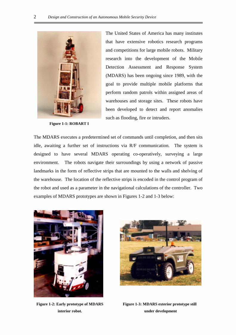
The world’s first autonomous security robot, ROBART I, was developed in 1982 by the
United States Naval Post-Graduate School and is shown in Figure 1-1. This robot
simply navigated its environment by following a reflective patrol path and as such, had
no sense of absolute location. It returned periodically to a recharging station by homing
in on an infrared beacon. Two further prototypes have been constructed since ROBART
I, with ROBART III, developed in 1992 to operate in urban warfare situations, the more
recent.
2 Design and Construction of an Autonomous Mobile Security Device
The United States of America has many institutes
that have extensive robotics research programs
and competitions for large mobile robots. Military
research into the development of the Mobile
Detection Assessment and Response System
(MDARS) has been ongoing since 1989, with the
goal to provide multiple mobile platforms that
perform random patrols within assigned areas of
warehouses and storage sites. These robots have
been developed to detect and report anomalies
such as flooding, fire or intruders.
The MDARS executes a predetermined set of commands until completion, and then sits
idle, awaiting a further set of instructions via R/F communication. The system is
designed to have several MDARS operating co-operatively, surveying a large
environment. The robots navigate their surroundings by using a network of passive
landmarks in the form of reflective strips that are mounted to the walls and shelving of
the warehouse. The location of the reflective strips is encoded in the control program of
the robot and used as a parameter in the navigational calculations of the controller. Two
examples of MDARS prototypes are shown in Figures 1-2 and 1-3 below:
Figure 1-2: Early prototype of MDARS
interior robot.
Figure 1-3: MDARS exterior prototype still
under development
Figure 1-1: ROBART I
Introduction 3
There has been little development of autonomous mobile robots in New Zealand. The
University of Canterbury has developed a large Automated Guided Vehicle (AGV) that
follows a buried wire around the warehouse floor and as such is not strictly autonomous
due to the exterior control feedback provided by the wire.
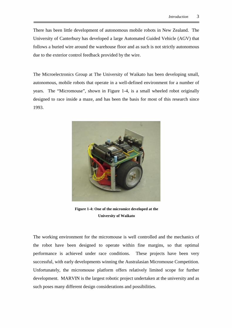
The Microelectronics Group at The University of Waikato has been developing small,
autonomous, mobile robots that operate in a well-defined environment for a number of
years. The “Micromouse”, shown in Figure 1-4, is a small wheeled robot originally
designed to race inside a maze, and has been the basis for most of this research since
1993.
Figure 1-4: One of the micromice developed at the
University of Waikato
The working environment for the micromouse is well controlled and the mechanics of
the robot have been designed to operate within fine margins, so that optimal
performance is achieved under race conditions. These projects have been very
successful, with early developments winning the Australasian Micromouse Competition.
Unfortunately, the micromouse platform offers relatively limited scope for further
development. MARVIN is the largest robotic project undertaken at the university and as
such poses many different design considerations and possibilities.
4 Design and Construction of an Autonomous Mobile Security Device
1.2 PROJECT OBJECTIVES
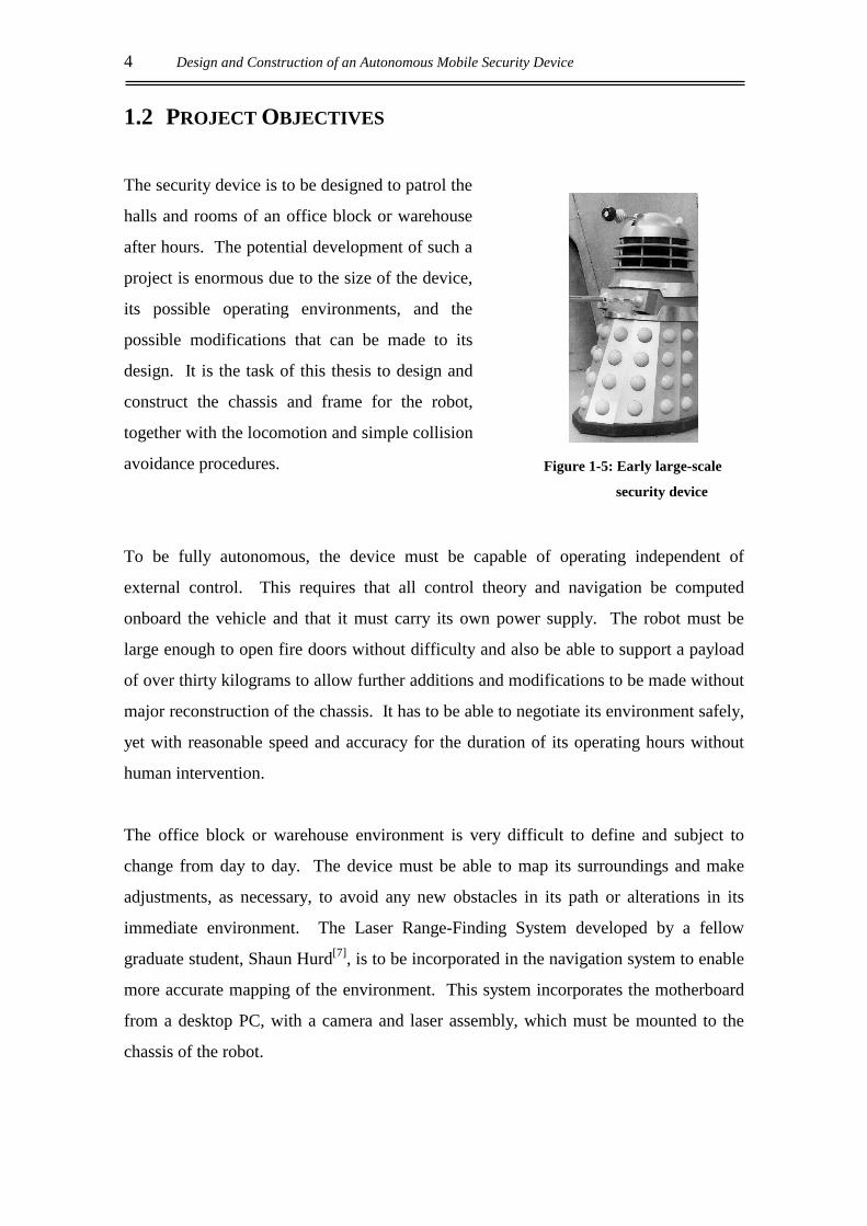
The security device is to be designed to patrol the
halls and rooms of an office block or warehouse
after hours. The potential development of such a
project is enormous due to the size of the device,
its possible operating environments, and the
possible modifications that can be made to its
design. It is the task of this thesis to design and
construct the chassis and frame for the robot,
together with the locomotion and simple collision
avoidance procedures.
To be fully autonomous, the device must be capable of operating independent of
external control. This requires that all control theory and navigation be computed
onboard the vehicle and that it must carry its own power supply. The robot must be
large enough to open fire doors without difficulty and also be able to support a payload
of over thirty kilograms to allow further additions and modifications to be made without
major reconstruction of the chassis. It has to be able to negotiate its environment safely,
yet with reasonable speed and accuracy for the duration of its operating hours without
human intervention.
The office block or warehouse environment is very difficult to define and subject to
change from day to day. The device must be able to map its surroundings and make
adjustments, as necessary, to avoid any new obstacles in its path or alterations in its
immediate environment. The Laser Range-Finding System developed by a fellow
graduate student, Shaun Hurd[7], is to be incorporated in the navigation system to enable
more accurate mapping of the environment. This system incorporates the motherboard
from a desktop PC, with a camera and laser assembly, which must be mounted to the
chassis of the robot.
Figure 1-5: Early large-scale
security device

Introduction 5
1.3 SPECIFICATIONS
The design of the robot must allow for the following features to be met. These
specifications are slightly flexible, but all efforts should be made meet or exceed them
wherever possible.
• Speed: The robot must move quickly enough to patrol its environment
at a suitable speed. It is deemed that a speed of 1m/s is
sufficient to achieve this.
• Height: The height of the robot is required to enable it to operate such
devices as a lift, when developments are added in the future.
Added height also gives the robot a physical presence. A height
of 1m is considered appropriate for these tasks.
• Weight: The robot needs to be heavy enough to give any additional
attachments a solid base from which to operate from. The robot
is also required to negotiate fire doors, which will require
substantial inertia. The weight of the robot is required to be at
least 30kg to achieve these goals.
• Power Supply: The robot must carry its own power supply, which will be
required to last the duration of its patrol. The supply must be
rechargeable and cost effective.
• Manoeuvrability: The robot is required to manoeuvre in the confines of an office
or corridor. This may involve obstacle avoidance or direction
reversal in spaces as small as 1m diameter.
• Power: The motors are required to drive the weight of the robot and any
additional payload at the speed specified above. The required
payload for the robot is set at 30kg.
• Flexibility: Due to the large scope for future additions and improvements to
be made to the original robot design, the chassis must be
flexible enough to ensure these developments can be made with
relative ease.
6 Design and Construction of an Autonomous Mobile Security Device
1.4 DEVELOPMENT
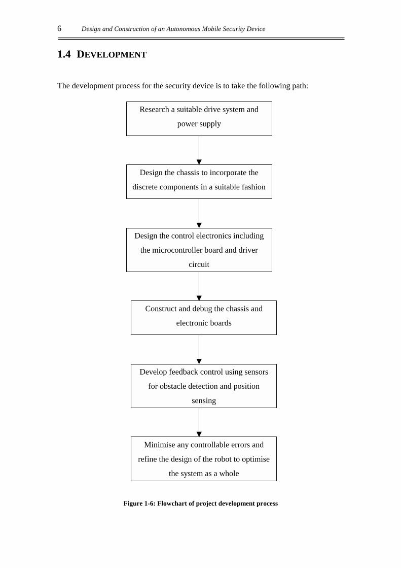
The development process for the security device is to take the following path:
Figure 1-6: Flowchart of project development process
Research a suitable drive system and
power supply
Design the chassis to incorporate the
discrete components in a suitable fashion
Design the control electronics including
the microcontroller board and driver
circuit
Construct and debug the chassis and
electronic boards
Develop feedback control using sensors
for obstacle detection and position
sensing
Minimise any controllable errors and
refine the design of the robot to optimise
the system as a whole
Introduction 7
The development of MARVIN can be seen as the first step in a series of work to be
conducted by the Physics and Electronic Engineering Department of the University of
Waikato. The versatility of this robotic platform will be a major advantage over projects
undertaken in the past and, although MARVIN is primarily designed as a large-scale
security device, there are a number of tasks that could be undertaken by a robot based on
a similar design strategy. Care must be taken therefore, to ensure that design decisions
will not limit possible future developments.

8 Design and Construction of an Autonomous Mobile Security Device
Hardware 9
2. HARDWARE
2.1 OVERVIEW
The hardware requirements for the large-scale security device can be met in a variety of
ways. The design of MARVIN’s chassis is dependent on the mobility configuration of
the device and the components of the drive system that it needs to accommodate. The
design of the hardware components will largely determine whether the device will meet
the design specifications outlined in Section 1.3.
The mobility configuration will determine the physical characteristics of the device and
how the individual components will be arranged on the chassis. The manoeuvrability
and controllability of MARVIN is determined by the physical arrangement of the drive
components in relation to the chassis and which steering system is employed.
The driving motors and gearing will determine the power supply requirements of the
device. MARVIN’s motors must be able to supply sufficient torque to the driving
wheels to enable the payload and speed requirements to be met. A gear train will be
implemented to reduce the performance expected of the motors and, consequently, the
power requirements of the system.
The individual hardware components are to be assembled on a suitable chassis that will
provide the device with strength and stability. The chassis will be employed in the future
to accommodate additional appendages and developments intended for a mobile robotic
platform. This will require a flexible design, which will enable these developments to be
made and which is strong enough to support the future payload requirements.

10 Design and Construction of an Autonomous Mobile Security Device
2.2 DRIVE SYSTEM
2.2.1 Mobility Configuration
The drive train is a critical component of a mobile robot and must be accommodated for
early in the chassis design. There are several factors that must be considered in order to
select an appropriate drive train configuration for MARVIN:
• Manoeuvrability – the specifications state that the robot must be able to manoeuvre
within a circle, one metre in diameter.
• Controllability – how difficult will the configuration be to control?
• Traction – the weight of MARVIN could be prone to wheel slippage if the driving
wheels do not have sufficient downward force.
• Stability – as MARVIN is to be one metre tall, the stability of the system is vital.
• Efficiency – how much energy is wasted in manoeuvring the vehicle?
• Maintenance – is the system prone to excessive wear or maintenance?
Some realistic options for the mobility configuration of MARVIN are listed below:
• The Tricycle
This method can either have a motor driving the rear wheels through a differential or
simply driving the front wheel alone. Both instances require a motor to control the
front wheel that pivots, enabling the robot to turn as shown in Figure 2-1A.
• The Quad (Ackerman steering)
This arrangement can have two or four wheel steering (illustrated in Figure 2-1B),
with the inside wheel at a slightly sharper angle than the outside in order to prevent
slippage caused by its tighter turning circle. If a two wheel steering arrangement were
implemented it would require a large motor for driving, a differential to transfer the
power evenly to the driving wheels and another motor to control the steering. A four-
wheel steering arrangement also requires a large driving motor coupled with a

Hardware 11
differential but would require two motors to control the steering. Four wheel steering
has a much tighter turning circle obtained from a similar sized chassis.
• The Wheelchair (Differential drive)
This method has the two drive wheels on the centre axis of the robot with castors or
skids at the front and rear to improve stability. The wheels are driven independently
and turning achieved by driving them in opposite directions. This allows the device
to turn 360 degrees around its centre shown in Figure 2-1C, below.
A: the tricycle B: the quad (four wheel steer version) C: the wheelchair
Figure 2-1: The three possible mobility configurations.
The wheelchair configuration is preferred to the quad and tricycle because of the tighter
turning circle which is imperative as MARVIN will be required to perform 90 and 180
degree turns in the confines of an office block corridor. With the wheelchair
configuration it is possible to design the chassis so that these turns can be executed on
the spot.
Both the tricycle and quad arrangements are susceptible to slippage as the centre of
gravity moves away from the driving wheels during acceleration and/or braking. They
can also cause surface damage and introduce a large strain on the steering components if
turning is executed while the mechatron is stationary. The control of a device that is
implementing either of these systems can also be complicated if it is required that the
device executes a three-point turn or travels in reverse. The differential drive system is
much less complicated to control due to the simplified mechanics of the system.
12 Design and Construction of an Autonomous Mobile Security Device
The driving wheels of the device will support as much of the weight as possible, with
castors being employed at the front and rear of the chassis to add stabilisation during
acceleration and braking manoeuvres.
2.2.2 Drive-train
The security device has to have an overall height of one metre to provide future
developments with a suitable basis from which to operate. As specified in the
introduction (Section 1.3), the bare robot is to weigh at least 30kg and be able to travel at
speeds of up to 1m/s. The driving motors must provide sufficient torque to the two
driving wheels to allow MARVIN to manoeuvre within these defined parameters of
operation. There are several factors that must be considered when choosing an
appropriate drive system:
• Capital cost
• Speed range
• Efficiency ratio - what is the ratio of input power to output power? Wasted energy
will generate heat and may introduce the need for a heat sink or fan.
• Controllability - what is the accuracy of the steady state operation of the drive
system?
• Braking - are mechanical brakes required or will gravitational braking be sufficient?
• Reliability
• Power to weight
• Power supply - how large will the batteries need to be?
Due to the physical size of the robot, the driving wheels are required to be of a
reasonable diameter. A large wheel diameter requires less torque from the driving
motors, but the effect of the robot’s inertia is increased and the braking force required is
increased. If very narrow wheels are used, the amount of energy lost from the system
due to friction is reduced, but the traction of the vehicle is reduced. When the drive train
is designed, the wheels must be considered, as they are the only means for the energy
from the motors to be translated into physical motion of the vehicle.
Hardware 13
Regardless of the particular drive system, the energy produced by the motors has to be
coupled to the driving wheels. There are a number of suitable configurations of motors
and gear trains that would create an appropriate drive system for the device. In the wheel
chair configuration, the drive wheels are mounted on the centre axis of the chassis and
support a majority of the load weight, which could be up to 60kg (as outlined in the
design specifications, Section 1.3). The following are the three main gearing
arrangements applicable for this application:
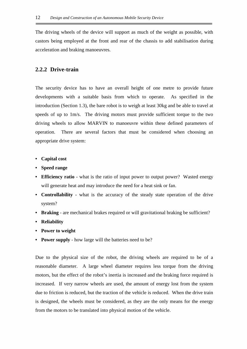
The Spur Gear
This is one of the simplest gearing arrangements.
The drive shaft from the motor is directly attached to
a gearhead which, if the gearbox is a speed reducer,
is meshed to a larger gear. Both gears are on the
same plane of motion with the gears meshing
parallel to each other. The speed reduction ratio is
simply the ratio of teeth on the gear being driven to
the number on the driving wheel. The axle of the
driving wheel can be directly linked to the larger of
the gears as shown in Figure 2-2.
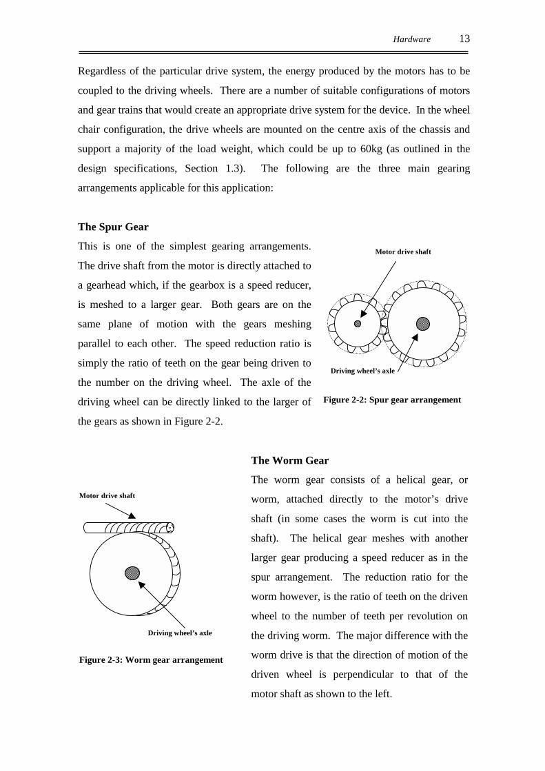
The Worm Gear
The worm gear consists of a helical gear, or
worm, attached directly to the motor’s drive
shaft (in some cases the worm is cut into the
shaft). The helical gear meshes with another
larger gear producing a speed reducer as in the
spur arrangement. The reduction ratio for the
worm however, is the ratio of teeth on the driven
wheel to the number of teeth per revolution on
the driving worm. The major difference with the
worm drive is that the direction of motion of the
driven wheel is perpendicular to that of the
motor shaft as shown to the left.
Motor drive shaft
Driving wheel’s axle
Figure 2-3: Worm gear arrangement
Motor drive shaft
Driving wheel’s axle
Figure 2-2: Spur gear arrangement
14 Design and Construction of an Autonomous Mobile Security Device
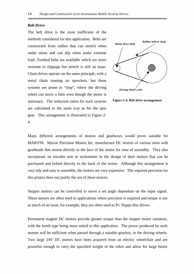
Belt Drive
The belt drive is the most inefficient of the
methods considered for this application. Belts are
constructed from rubber that can stretch when
under stress and can slip when under extreme
load. Toothed belts are available which are more
resistant to slippage but stretch is still an issue.
Chain drives operate on the same principle, with a
metal chain running on sprockets, but these
systems are prone to “slop”, where the driving
wheel can move a little even though the motor is
stationary. The reduction ratios for such systems
are calculated in the same way as for the spur
gear. This arrangement is illustrated in Figure 2-
4.
Many different arrangements of motors and gearboxes would prove suitable for
MARVIN. Maxon Precision Motors Inc. manufacture DC motors of various sizes with
gearheads that mount directly to the face of the motor for ease of assembly. They also
incorporate an encoder unit or tachometer in the design of their motors that can be
purchased and bolted directly to the back of the motor. Although this arrangement is
very tidy and easy to assemble, the motors are very expensive. The required precision for
this project does not justify the use of these motors.
Stepper motors can be controlled to move a set angle dependant on the input signal.
These motors are often used in applications where precision is required and torque is not
as much of an issue, for example, they are often used in PC floppy disc drives.
Permanent magnet DC motors provide greater torque than the stepper motor variation,
with the brush type being more suited to this application. The power produced by such
motors will be sufficient when passed through a suitable gearbox, to the driving wheels.
Two large 24V DC motors have been acquired from an electric wheelchair and are
powerful enough to carry the specified weight of the robot and allow for large future
Motor drive shaft Rubber belt or chain
Driving wheel’s axle
Figure 2-4: Belt drive arrangement

Hardware 15
payloads. The speed of the drive wheels is approximately walking pace, which is within
the design specifications.
The motors are permanent magnet brush motors, with a worm gearbox mounted to the
face of the motor. The shaft from the helical gear of the worm drive has a small spur
gear mounted to it that is held in place with a key and grub-screw. The spur gear is
configured in a planetary arrangement, not as the traditional spur gear arrangement
outlined above. The physical workings of the gear system are very similar to that of a
standard spur, but instead of the smaller gear mating to the outside of the larger as in
Figure 2-2, it runs around the inside of the larger, ring gear as illustrated in Figure 2-5:
Figure 2-5: Planetary gearhead on the motor shaft driving the wheel
The worm has three teeth per revolution cut directly onto the motor shaft and drives a 51
tooth helical gear. This produces a reduction ratio of Nworm = 17:1 to the drive shaft, on
which the 24 tooth planetary gear is mounted. This gear is mated directly to the wheel
ring gear that has 75 teeth. The reduction ratio from the motor to the wheel is calculated
using Equation [2-1] below:

16 Design and Construction of an Autonomous Mobile Security Device
17*2475*
=
= worm
gearhead
wheel NNN
N
1:56.51= Eqn. [2-1] where: N = reduction ratio
Nwheel = gearing ratio of wheel
Ngearhead = gearing ratio of planetary gear head
Nworm = gearing ratio of worm drive
This shows that for every revolution of the driving wheel, the motor must turn 51.56
revolutions. Figure 2-6 shows the total arrangement of the gear train for the drive
system:
Figure 2-6: Close up view of gearbox and planetary gearhead
To allow for feedback control, odometers are attached to the back of the motors and are
directly attached to the motor shaft. This was achieved by turning down a brass shaft on
a metalwork lathe and tapping a thread into the back of the motor. The code-wheel of
the shaft encoder is attached to the shaft with a grub-screw and experiences the same
gearing as the motor, that is, N.
Helical gear
Worm
(Motor shaft)
Ring gear
Planetary gear

Hardware 17
2.3 POWER SUPPLY
2.3.1 Battery Options
In order for the power supply of MARVIN to be portable, batteries must be used to
supply the required power to the driving motors and control electronics. With so many
different types available, choosing an appropriate arrangement for this application is an
involved process. There are many different types of battery available on the market,
each aimed a specific application:
• Nickel Cadmium (NiCd) – commonly used in cellular phones and power tools, these
batteries can be deeply discharged repeatedly with no loss of performance and
can be rapidly charged. The battery is prone to crystalline formation if not
completely discharged before being replenished, giving the battery a
“memory” which reduces the capacity considerably. The large voltage
requirements of the security device would require a series of large batteries at
significant cost.
• Sealed Lead Acid (SLA) – These are approximately half the price of comparative
NiCd batteries, although they weigh a lot more due to the lead plates used in
construction. Commonly known as a gelcell battery, they are popular in
portable devices due to the absence of liquid acid, which can leak from the
cells and the low maintenance requirements in comparison to the flooded lead
acid variation. The SLA is not subject to memory but does have a very long
charge time (8 to 16 hours) and must always be stored in the charged state to
prevent the plates from forming a sulphate which can make recharging
difficult or impossible.
• Flooded Lead Acid (FLA) – These are the more common variation of the SLA used
primarily in automotive applications. The FLA must be stored upright to
prevent acid leakage, but is by far the cheapest option and most suitable for
this application where size and weight are not significant factors. The deep
cycle variety of FLA can be repeatedly discharged and charged without
degradation of performance.
18 Design and Construction of an Autonomous Mobile Security Device
The flooded lead acid battery is chosen above the others listed, as it is more readily
available and the much less expensive option. The batteries can be easily secured to the
chassis with a metal bracket and held in the upright position, making the gelcell variation
unnecessary. There is a wide range of FLA batteries available on the market, each
designed to perform a specific task.
The batteries supplying power to the driving motors and accessories of MARVIN need
to provide relatively low current over a long period, with infrequent recharging. If a
standard automotive lead acid battery (known as a starting battery) is heavily discharged
and recharged repeatedly, premature failure is likely. This makes the starting battery
unsuitable for the final design of the security device where reliability is a concern.
Deep cycle batteries are specifically designed to be run flat and recharged repeatedly
without sacrificing their capacity. The material used in the construction of the battery is
much denser than that used in a standard battery. Additionally, specially designed glass
mats are placed between the lead plates to prevent the shedding of active material (lead)
during charging and damage caused by vibrations. The disadvantage of these batteries is
the added initial cost of purchase, with most variations over twice the price of a standard
battery.
2.3.2 Battery Classification
For many years batteries have been rated in terms of “Amp Hours”. This was a
statement of the current that could be provided continuously by the battery for 20 hours.
While this does give a vague indication of the capacity of the battery, it gives no
indication of the battery’s ability to power high load accessories. Battery manufacturers
in New Zealand have adopted the SAE (Society of Automotive Engineers) standard,
whereby a battery’s capacity is rated in terms of Cold Cranking Amps (CCA) and
Reserve Capacity (RC).
The CCA of a battery gives a more accurate indication of its performance than simple
Amp Hours. It is defined as the discharge load in amperes that a new, fully charged
Hardware 19
battery can deliver at -18°C for 30 seconds whilst maintaining a minimum voltage of
1.2V per cell. The higher the CCA, the more powerful the battery.
The RC of a battery is expressed in minutes. It represents the time a new, fully charged
battery will supply a constant load of 25A at 25°C without the voltage dropping below
10.5V for a 12V battery. This rating is more applicable to deep cycle batteries that are
designed to power auxiliary items such as lights and motors, rather than high-load engine
cranking.
2.3.3 Battery Selection
Ideally the power supply for the security device would be a deep cycle lead acid variety,
but as the robot will only be required to run for short periods during development and
testing, the deep cycle nature of the battery is not essential. Two standard 12V starting
batteries have been connected in series to provide the required 24V at half the price of a
deep cycle variation. The voltage levels of these batteries are to be regularly monitored
to ensure they are never run flat and subsequently damaged. The batteries can be
replaced at a later date (once the robot is required to operate for longer periods at a time)
with a deep cycle variation due to the similarity in the external dimensions.
The maximum current drawn by the driving motors is found experimentally to be
approximately 10A when travelling at its maximum speed. If the batteries are expected
to run continuously for approximately two hours, the required RC value is 60 minutes.
The batteries chosen to power the device during development have the following
characteristics:
Manufacturer: Champion Batteries
Model: 126HD Silver battery
RC: 55 minutes
CCA: 310 A
When powered by these batteries MARVIN can be expected to run for 110 minutes at
full power before recharging would be necessary.
20 Design and Construction of an Autonomous Mobile Security Device
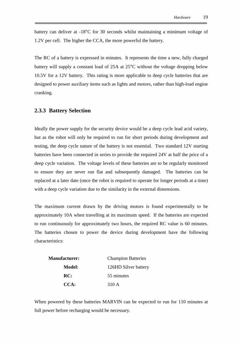
2.3.4 Recharging the Batteries
The batteries have been wired into two circuits, one to supply the power to the motors
and control electronics and one for recharging the batteries. Panel mounted sockets have
been installed in the chassis frame so that the batteries can be recharged without being
removed or the terminals being accessed. These sockets are wired in parallel so that if
both positive and negative rails of a 12 V power supply are used, the batteries will
charge faster and more evenly than if a single 24V rail were used to charge both batteries
in series. The wiring diagram below is colour coded to match the socket used on
MARVIN.
The lead in the plates of the batteries contributes significantly to the overall weight of
MARVIN. The two driving motors weigh approximately 5.5kg each and the bare
chassis weighs 10kg. As the batteries are approximately 20kg each they make up over
60% of the overall weight. The advantage of this weight is that it can be incorporated
into the design of the chassis to create a low centre of gravity, increasing stability by
counteracting the height of the device.
2.4 CHASSIS DESIGN
MARVIN’s chassis needs to be of a suitable size to patrol the corridors of an office
block and manoeuvre in the space allowed. The robot has to be large enough to support
+12V
GND
-12V
Power supply to motors etc.
-12V
Supply rails from power pack
Figure 2-7: Wiring diagram for batteries
Hardware 21
the weight of its power supply and any additional payloads that may be added at a later
stage. The chassis has been designed to be as flexible as possible to allow for future
development whilst not sacrificing the overall strength.
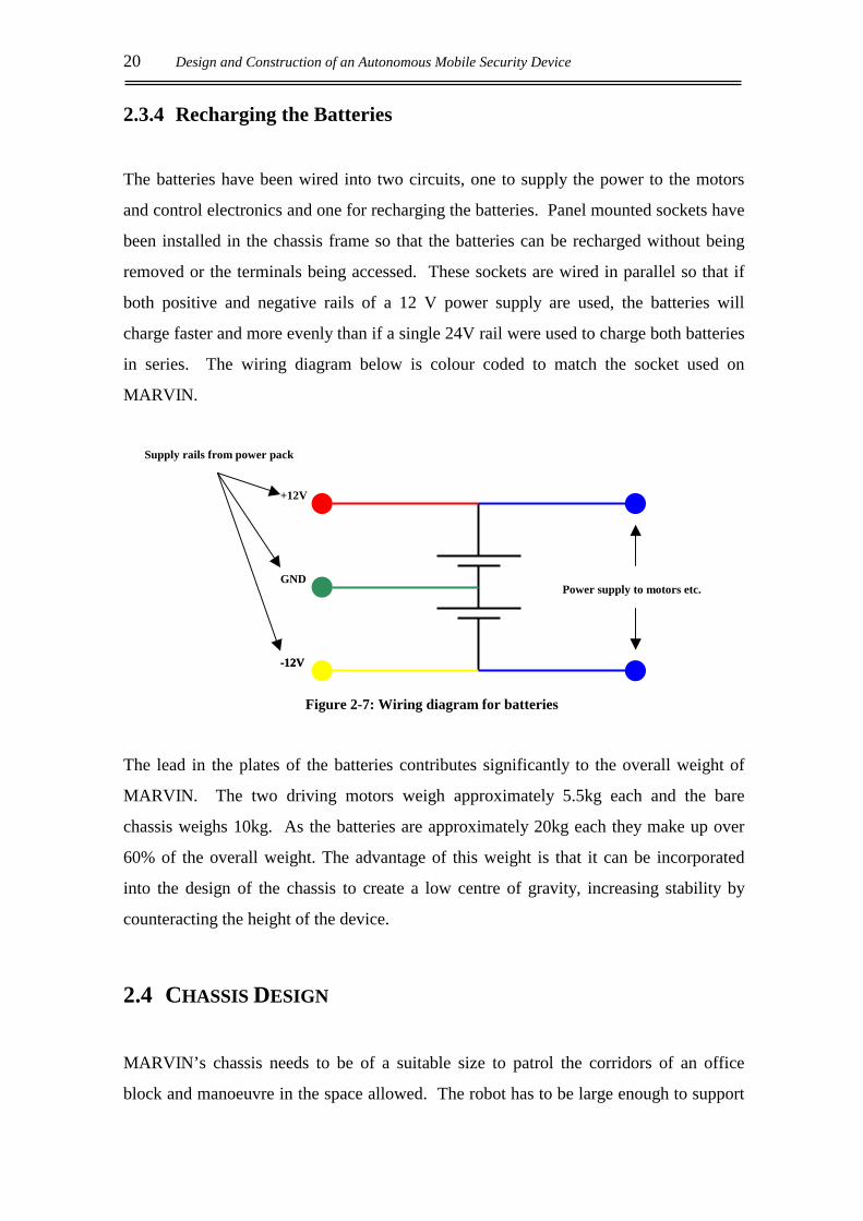
Figure 2-8 shows the chassis of the security device, which has been designed and
constructed in two major parts, the base and the frame. The base is designed to act as the
backbone of the entire device with the wheels, frame and batteries directly attached to it.
This arrangement causes all the stresses of the singular parts to be relayed back through
the base, and as such it must be very strong.
Figure 2-8: Steel chassis base (black) with aluminium
frame and bumper
The material chosen for the construction of the base is 3 mm thick square steel tubing,
the exterior dimensions of the tubing are 25 mm x 25 mm. The individual sections of
steel are fastened together using a Metal Inert Gas welder (MIG). The steel has been
welded on all four sides of the joint to produce an extremely strong and unyielding
structure from which the remaining parts of the security device can be assembled.
The upper frame of the chassis has been constructed from extruded aluminium in an
attempt to reduce excess weight. The frame is assembled using bolts and rivets which,
unlike welding, allows the design to be kept modular and can be disassembled without
22 Design and Construction of an Autonomous Mobile Security Device
the destruction of its components. The design also allows for further extensions and
modifications to be made easily without major chassis redesign. Due to the height of the
framing above the base chassis, it is necessary to cross-brace the structure to increase
stability and strength. Attachments such as the laser range-finding assembly and PC
motherboard are bolted to the primary framework with the aid of further aluminium
railings to ensure that all components are securely held in place.
MARVIN’s driving motors are mounted to a section of 5mm steel plate, which is
securely welded to the base structure. Three bolts hold each of the motors firmly in
place, with the planetary gearheads mounted to their drive shafts. The gearhead mates
with the ring gear on the inside of wheel rim. The wheel is bolted to the same plate as
the motors to ensure that the gears mesh together in a tight fit to reduce any “slop” in the
wheels.
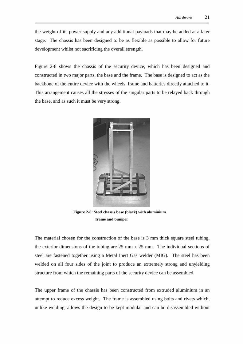
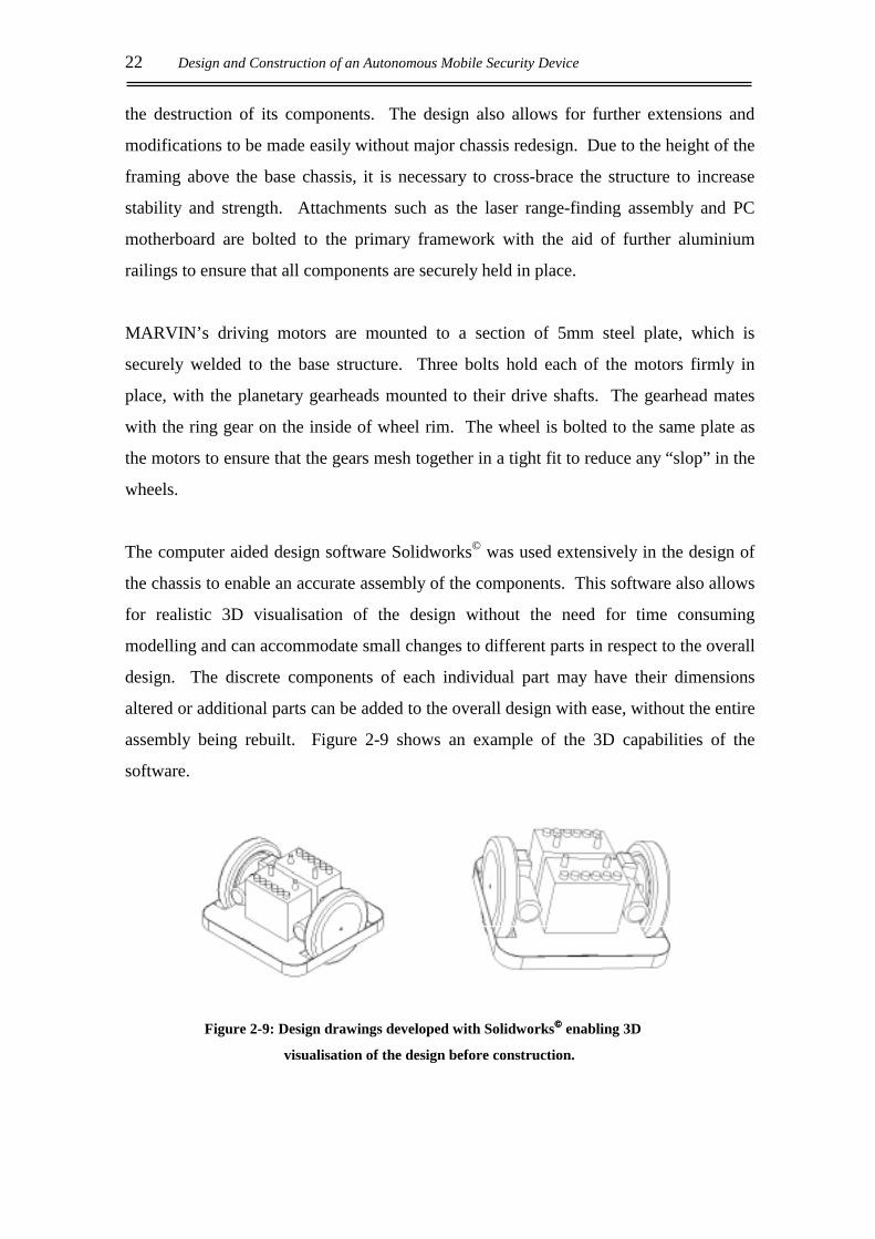
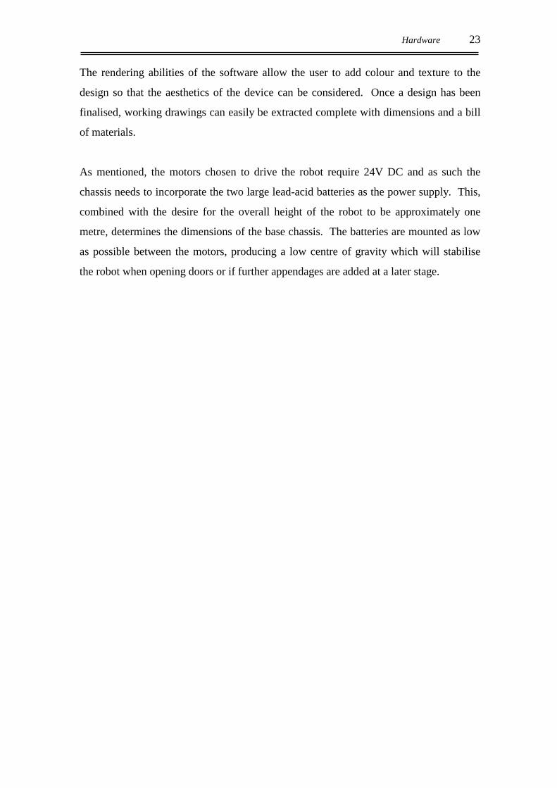
The computer aided design software Solidworks© was used extensively in the design of
the chassis to enable an accurate assembly of the components. This software also allows
for realistic 3D visualisation of the design without the need for time consuming
modelling and can accommodate small changes to different parts in respect to the overall
design. The discrete components of each individual part may have their dimensions
altered or additional parts can be added to the overall design with ease, without the entire
assembly being rebuilt. Figure 2-9 shows an example of the 3D capabilities of the
software.
Figure 2-9: Design drawings developed with Solidworks enabling 3D
visualisation of the design before construction.
Hardware 23
The rendering abilities of the software allow the user to add colour and texture to the
design so that the aesthetics of the device can be considered. Once a design has been
finalised, working drawings can easily be extracted complete with dimensions and a bill
of materials.
As mentioned, the motors chosen to drive the robot require 24V DC and as such the
chassis needs to incorporate the two large lead-acid batteries as the power supply. This,
combined with the desire for the overall height of the robot to be approximately one
metre, determines the dimensions of the base chassis. The batteries are mounted as low
as possible between the motors, producing a low centre of gravity which will stabilise
the robot when opening doors or if further appendages are added at a later stage.

24 Design and Construction of an Autonomous Mobile Security Device

Control Electronics 25
3. CONTROL ELECTRONICS
The control of the driving motors is accomplished with the use of a microcontroller,
which can be programmed from a PC using the C Programming Language. The
microcontroller will deliver commands to the motors of the device via the driver
circuitry. The motor driver has been designed to limit the current delivered to the
motors and controls the consequent speed of the driving wheels.
3.1 THE MICROCONTROLLER
The microcontroller used to control the drive system is the Phillips 87C552 (‘552). The
device is based on the 8051 architecture and has the following features:
• 8k byte EPROM (one time programmable)
• 256 bytes of internal RAM
• Five 8-bit I/O ports
• One 8-bit input port
• Two 16-bit timers/event counters
• An additional 16-bit timer for capture and compare
• A fifteen source, two priority level, nested interrupt structure
• An 8-input ADC
• A dual DAC PWM interface
• Two serial interfaces (I2C bus and UART)
• A watchdog timer
• Can be extended using standard TTL memories and logic
26 Design and Construction of an Autonomous Mobile Security Device
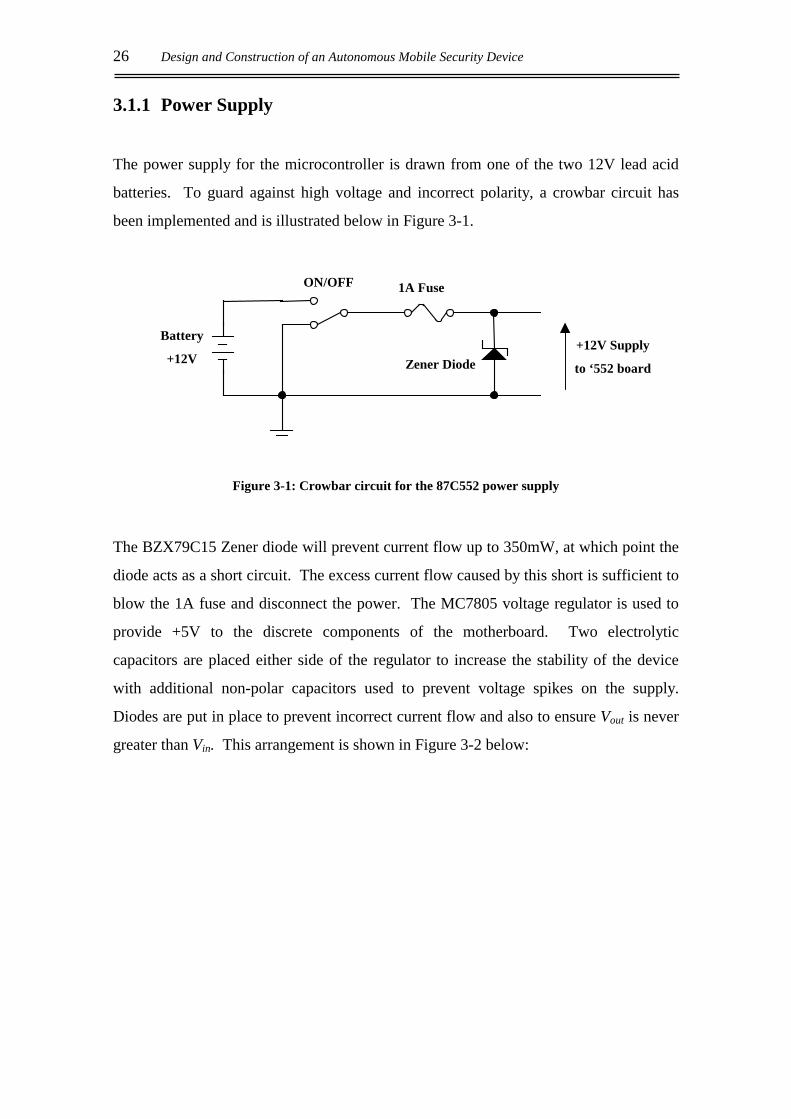
3.1.1 Power Supply
The power supply for the microcontroller is drawn from one of the two 12V lead acid
batteries. To guard against high voltage and incorrect polarity, a crowbar circuit has
been implemented and is illustrated below in Figure 3-1.
Figure 3-1: Crowbar circuit for the 87C552 power supply
The BZX79C15 Zener diode will prevent current flow up to 350mW, at which point the
diode acts as a short circuit. The excess current flow caused by this short is sufficient to
blow the 1A fuse and disconnect the power. The MC7805 voltage regulator is used to
provide +5V to the discrete components of the motherboard. Two electrolytic
capacitors are placed either side of the regulator to increase the stability of the device
with additional non-polar capacitors used to prevent voltage spikes on the supply.
Diodes are put in place to prevent incorrect current flow and also to ensure Vout is never
greater than Vin. This arrangement is shown in Figure 3-2 below:
Battery
+12V
ON/OFF 1A Fuse
Zener Diode+12V Supply
to ‘552 board

Control Electronics 27
Figure 3-2: The voltage regulating circuit
3.1.2 Reset Circuitry
The reset circuitry on the motherboard allows the user to reset the ‘552 as required. An
internal reset is executed in the second machine cycle in which the RST pin of the
87C552 chip is logic high and is repeated every cycle until the pin goes low. To ensure
RST is held high for long enough to perform a chip reset, a capacitor is placed in parallel
with a push button switch so that after the switch has shorted the capacitor, it will
slowly charge causing RST to drop to logic low. This arrangement is shown in Figure 3-
3 below. The value of this capacitor is chosen so that the time for RST to drop to logic
low is longer than two machine cycles.
Figure 3-3: Reset circuitry
A resistor is placed in series with the switch to slow the discharge of the capacitor. This
prevents the microcontroller from being accidentally reset if the switch is
VIN +5V
COM+12V
Voltage Regulator
Power Indicator
Protection Diodes
Stabilising Capacitors
+5V
(Vcc)
Push button switch
RST Vcc
Timing capacitor

28 Design and Construction of an Autonomous Mobile Security Device
unintentionally pressed momentarily. Once the ‘552 is reset, I/O Ports 1 to 4 are set
high, while Port 5 is undetermined.
3.1.3 Watchdog Timer
The watchdog timer of the 87C552 is designed to reset the chip and reboot the device
should a software lockup occur. This function is rarely used as it introduces the chance
of the chip being reset accidentally. A three pin jumper has been used to set the Not
Watchdog Enable pin of the ‘552 either on or off. This method is less invasive of board
space than a switch.
3.1.4 Memory Allocations
The 8k byte EPROM of the ‘552 is used to store the download code which outlines how
the chip is to store data downloaded from the PC. The microcontroller will run this
code when reset with the Run/Download switch in the Download position. When the
switch is in the run position all functions are performed from external memory.
The microcontroller’s motherboard incorporates two external 32k 8-bit Static RAM
chips (KM62256CL) in a mapped memory configuration, one for storing program data
and one as a data memory. Although the onboard EPROM of the ‘552 is sufficient to
store the simple control algorithms for MARVIN, the additional external RAM provides
ample memory for more complex programs that may be implemented in the future.
The RAM is corruptible during a power down and as such a “Smart Socket” is used for
the program memory to provide a battery backup, thus preventing the need to download
fresh code whenever the board is switched off. A low power RAM is used in
conjunction with the smart socket to draw as little power as possible from the back-up
battery when in use. This socket is not required for the data memory, as it is only
accessed by the ‘552 to store variables and other parameters when running a program.
This data is not vital and does not need to be available at start-up.

Control Electronics 29
There are 15 address lines on each of the RAM chips, which are configured as input
only lines. The external memory is accessed by the microcontroller through Ports 0 and
2. Port 0 outputs the low order 8 bits of the external memory address and is also used as
a data line for both RAM chips. The 74HCT573 latch is used to control the data being
written to the external memory. The latch stores the data until the Address Latch Enable
line drops low. This ensures the correct address has been set on the RAM when the
write instruction is given.
Port 2 outputs the upper 7 bits of the address bus, with the eighth, most significant bit
(A15) used to select between the two RAM chips through an inverting transistor circuit.
This circuit sets Not Chip Select of the data memory to be the inverse of whatever logic
is present on the gate of the BST70A transistor. A 1kΩ resistor is used to prevent a
short circuit when the MOSFET is open. The inverting circuit is shown in Figure 3-4.
Figure 3-4: Inverter circuit for mapping of external memory
When A15 is high, the MOSFET is switched on and the Not Chip Select pin of the data
RAM is set low, selecting the data memory. If A15 were set low, the MOSFET is
switched off and the Not Chip Select on the data RAM is set high. The Not Chip Select
pin of the program RAM is hardwired to A15 and so its selection is determined directly
from P2.7. This will always be the inverse of the control signal for the data memory.
The Not Program Store Enable (NPSEN) pin of the ‘552 is used as the read strobe to
access the external program memory. This strobes the Output Enable pin of the RAM
low whenever the Run/Download switch is set to Run. The Not Write Enable pin of the
program RAM is only set low when data is downloaded from the PC.
Vcc
1kΩΩΩΩ
BST70A
MOSFET
Not Chip Select
(data memory)
Port 2.7
30 Design and Construction of an Autonomous Mobile Security Device
3.1.5 Buffer
The multi-channel MAX232 driver/receiver is used to buffer the serial signals received
from the PC and those sent by the 87C552 via the serial output port (Port 3.1). The
buffer scales the voltage of the incoming signal, from the ±10V sent by the PC, so that
the voltage received by the microcontroller is between +5V (Vcc) and GND. The buffer
can also be used as a driver to produce an output swing of up to ±8V.
The serial port of the microcontroller is a Universal Asynchronous Receiver/Transmitter
(UART) port and can transmit and receive simultaneously. The data being sent and
received between the PC and microcontroller consists of a start bit, 8 data bits (LSB
first) and a tenth stop bit.
3.1.6 Run/Download Circuitry
A Double-pole/Double-throw (DPDT) switch is implemented to swap the
microcontroller between run and download modes of operation. When in the Download
position, the Not External memory Enable (NEA) pin of the ‘552 is set high, causing the
microcontroller to run from its internal ROM. In this position the switch also connects
the Receive Data Out (RDO) pin of the MAX232 buffer to Port3.1 on the ‘552, which is
the serial input port. If the microcontroller is reset with the switch in this position, it
will reboot from the download code stored on the internal ROM and sit idle, waiting to
receive data from the PC via the 9-pin D-connector on the motherboard.
The 9-pin D-connector is wired in the format of a standard null-modem cable, with
many of the connector’s pins left unused. The relevant connections for the cable are:
• Pin 2: Transmit line
• Pin 3: Receive line
• Pin 5: Earth line

Control Electronics 31
If the DPDT switch is in the Run position, NEA is set low and the ‘552 will reboot from
external program memory when reset. In this position, the Receive Serial Data (RXD)
pin of the microcontroller is connected to the transmitted serial output of the MAX232,
with Transmit Serial Data (TXD) connected to the transmitted serial input. This enables
serial transmission and reception through the buffer attached to the dedicated 10-pin
header on the motherboard.
3.1.7 Port Structure
The 87C552 microcontroller has six 8-bit ports, which it uses to communicate with the
peripheral components on the motherboard. Port 0 and Port 2 are the address buses for
the external Data and Program memories. Ports 1,3,4 and 5 are multifunctional and can
be accessed through the 10 pin headers of the motherboard. Their alternate functions
are listed in Table 3.1.
Port Alternate Function
P1.0, 1, 2, 3 Capture Timer input signals for Timer 2
P1.4 Timer 2 event input
P1.5 Timer 2 reset signal
P1.6 Serial clock line (I2C bus)
P1.7 Serial port line (I2C bus)
P3.0 Serial input port (UART)
P3.1 Serial output port (UART)
P3.2 External interrupt 0
P3.3 External interrupt 1
P3.4 Timer 0 external input
P3.5 Timer 1 external input
P3.6 External data memory write strobe
P3.7 External data memory read strobe
P4.0, 1, 2, 3, 4, 5 Timer 2: compare and set/reset outputs
on a match with Timer 2
P4.6, 7 Timer 2 compare and toggle outputs on a
match with timer 2
Port 5 Eight analog ADC inputs
Table 3.1: Input/Output ports of the 87C552 microcontroller
32 Design and Construction of an Autonomous Mobile Security Device
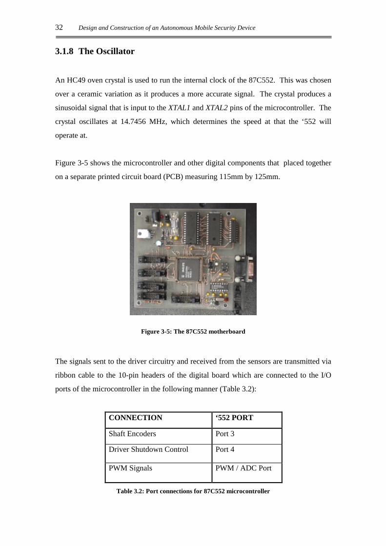
3.1.8 The Oscillator
An HC49 oven crystal is used to run the internal clock of the 87C552. This was chosen
over a ceramic variation as it produces a more accurate signal. The crystal produces a
sinusoidal signal that is input to the XTAL1 and XTAL2 pins of the microcontroller. The
crystal oscillates at 14.7456 MHz, which determines the speed at that the ‘552 will
operate at.
Figure 3-5 shows the microcontroller and other digital components that placed together
on a separate printed circuit board (PCB) measuring 115mm by 125mm.
Figure 3-5: The 87C552 motherboard
The signals sent to the driver circuitry and received from the sensors are transmitted via
ribbon cable to the 10-pin headers of the digital board which are connected to the I/O
ports of the microcontroller in the following manner (Table 3.2):
CONNECTION ‘552 PORT
Shaft Encoders Port 3
Driver Shutdown Control Port 4
PWM Signals PWM / ADC Port
Table 3.2: Port connections for 87C552 microcontroller
Control Electronics 33
The full schematic of the microcontroller motherboard can be found in Appendix A.1.
3.2 MOTOR DRIVER CIRCUIT
3.2.1 The H-bridge
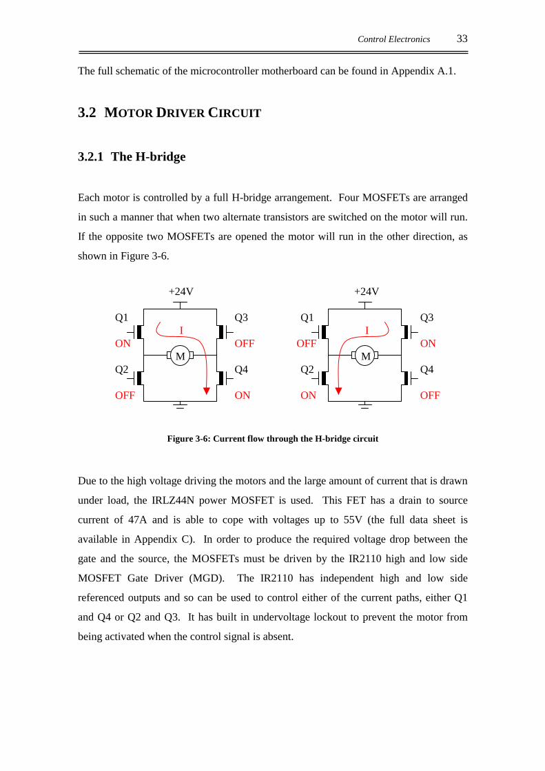
Each motor is controlled by a full H-bridge arrangement. Four MOSFETs are arranged
in such a manner that when two alternate transistors are switched on the motor will run.
If the opposite two MOSFETs are opened the motor will run in the other direction, as
shown in Figure 3-6.
+24V +24V Q1 Q3 Q1 Q3 I I ON OFF OFF ON M M Q2 Q4 Q2 Q4 OFF ON ON OFF
Figure 3-6: Current flow through the H-bridge circuit
Due to the high voltage driving the motors and the large amount of current that is drawn
under load, the IRLZ44N power MOSFET is used. This FET has a drain to source
current of 47A and is able to cope with voltages up to 55V (the full data sheet is
available in Appendix C). In order to produce the required voltage drop between the
gate and the source, the MOSFETs must be driven by the IR2110 high and low side
MOSFET Gate Driver (MGD). The IR2110 has independent high and low side
referenced outputs and so can be used to control either of the current paths, either Q1
and Q4 or Q2 and Q3. It has built in undervoltage lockout to prevent the motor from
being activated when the control signal is absent.
34 Design and Construction of an Autonomous Mobile Security Device
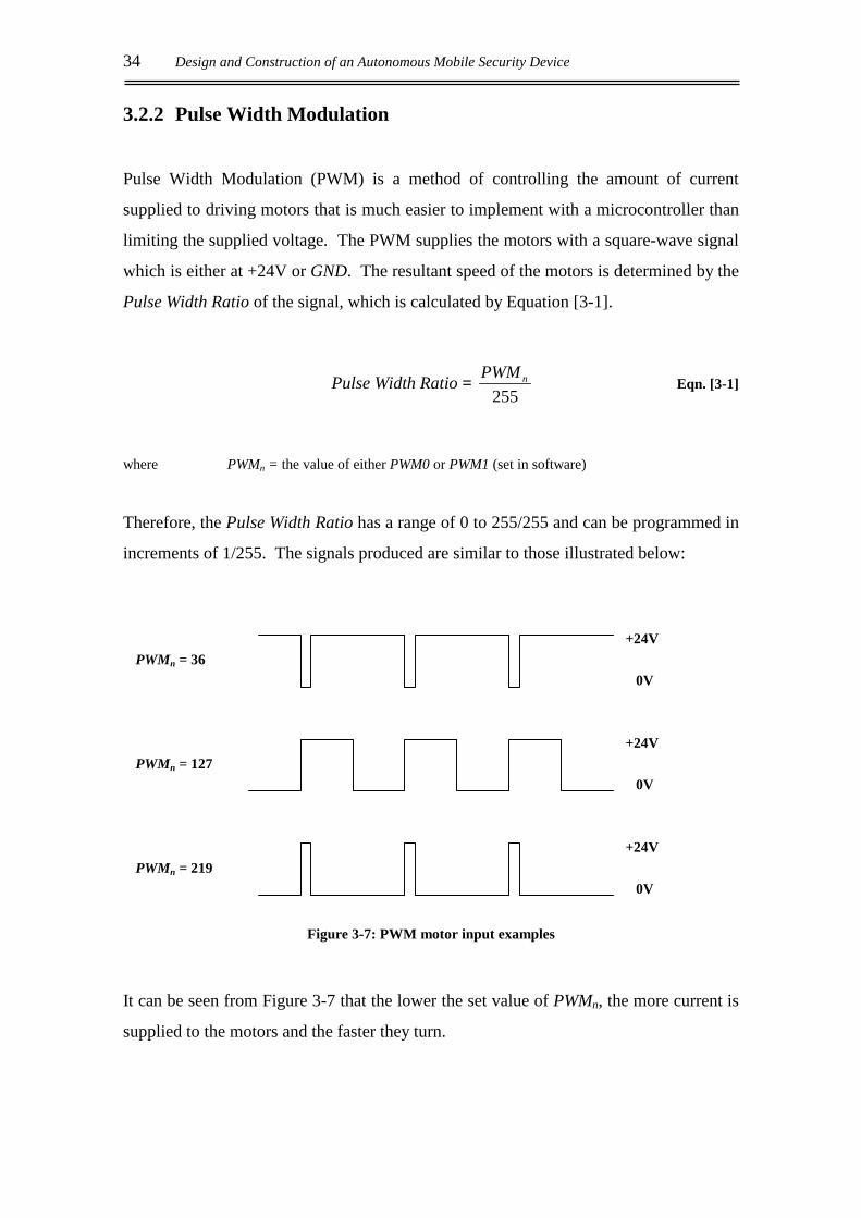
3.2.2 Pulse Width Modulation
Pulse Width Modulation (PWM) is a method of controlling the amount of current
supplied to driving motors that is much easier to implement with a microcontroller than
limiting the supplied voltage. The PWM supplies the motors with a square-wave signal
which is either at +24V or GND. The resultant speed of the motors is determined by the
Pulse Width Ratio of the signal, which is calculated by Equation [3-1].
Pulse Width Ratio = 255
nPWM Eqn. [3-1]
where PWMn = the value of either PWM0 or PWM1 (set in software)
Therefore, the Pulse Width Ratio has a range of 0 to 255/255 and can be programmed in
increments of 1/255. The signals produced are similar to those illustrated below:
Figure 3-7: PWM motor input examples
It can be seen from Figure 3-7 that the lower the set value of PWMn, the more current is
supplied to the motors and the faster they turn.
0V
+24V PWMn = 127
0V
+24V PWMn = 219
0V
+24V PWMn = 36
Control Electronics 35
PWMP controls the frequency of the PWM signal, fPWM, and has been set to zero so that
it has the maximum value as calculated using Equation [2-2] below:
( ) 25512 ×+×=
PWMPff OSC
PWM Eqn. [3-2]
The frequency of the oscillator fOSC = 14.75MHz, so the value of fPWM = 28.9 kHz. The
PWM signal is sent to both the high and low side transistors of the H-bridge. This
makes it possible to control the speed of two motors using one microcontroller, as there
are only two PWM outputs available on the 87C552
The PWM signal from the 80C552 microcontroller is passed through the MC14504B
CMOS level shifter to both inputs of the MOSFET driver. This raises a logic high
signal from the ‘552 from +5V to the required +15V for the MGD input. It is the PWM
that determines the speed of the motors by altering the duty cycle of the 24V signal that
passes through the motor, the longer the signal is high per cycle, the faster the motor
will turn.
3.2.3 Hardware Protection
As the inputs of the MGD are always receiving the PWM signal, it is the shutdown pin
(SD) of the IR2110 which is used to control the direction, if any, of the motor. The pair
of driver chips are configured in such a way that when the first is on and the other is off,
the motor will travel in the reverse direction to that when the first is off and the other is
on. Care is required to ensure that both current paths are never open at the same time as
this will result in a short circuit between +24V and ground through the transistors. The
transistors are not able to cope with such current and would destruct. To prevent this
situation from arising accidentally, a Programmable Logic Device (PLD) has been
employed as hardware protection. The program in the PLD produces the following truth
table:
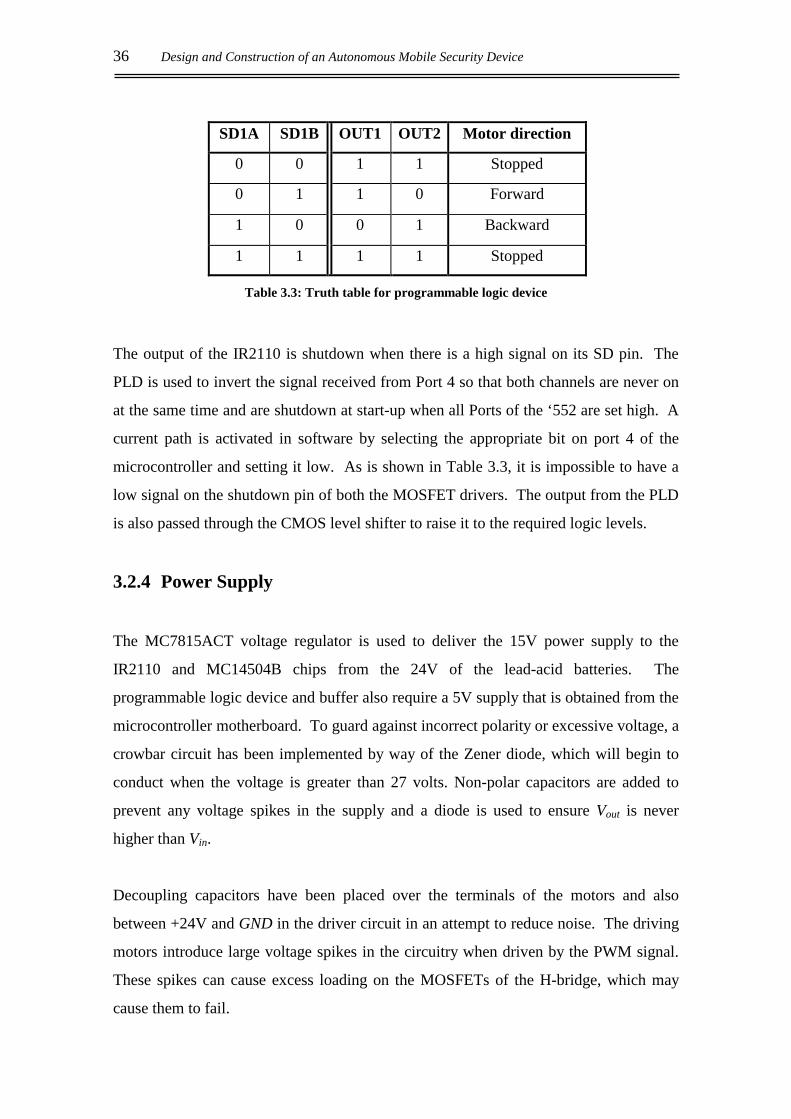
36 Design and Construction of an Autonomous Mobile Security Device
SD1A SD1B OUT1 OUT2 Motor direction
0 0 1 1 Stopped
0 1 1 0 Forward
1 0 0 1 Backward
1 1 1 1 Stopped
Table 3.3: Truth table for programmable logic device
The output of the IR2110 is shutdown when there is a high signal on its SD pin. The
PLD is used to invert the signal received from Port 4 so that both channels are never on
at the same time and are shutdown at start-up when all Ports of the ‘552 are set high. A
current path is activated in software by selecting the appropriate bit on port 4 of the
microcontroller and setting it low. As is shown in Table 3.3, it is impossible to have a
low signal on the shutdown pin of both the MOSFET drivers. The output from the PLD
is also passed through the CMOS level shifter to raise it to the required logic levels.
3.2.4 Power Supply
The MC7815ACT voltage regulator is used to deliver the 15V power supply to the
IR2110 and MC14504B chips from the 24V of the lead-acid batteries. The
programmable logic device and buffer also require a 5V supply that is obtained from the
microcontroller motherboard. To guard against incorrect polarity or excessive voltage, a
crowbar circuit has been implemented by way of the Zener diode, which will begin to
conduct when the voltage is greater than 27 volts. Non-polar capacitors are added to
prevent any voltage spikes in the supply and a diode is used to ensure Vout is never
higher than Vin.
Decoupling capacitors have been placed over the terminals of the motors and also
between +24V and GND in the driver circuit in an attempt to reduce noise. The driving
motors introduce large voltage spikes in the circuitry when driven by the PWM signal.
These spikes can cause excess loading on the MOSFETs of the H-bridge, which may
cause them to fail.
Control Electronics 37
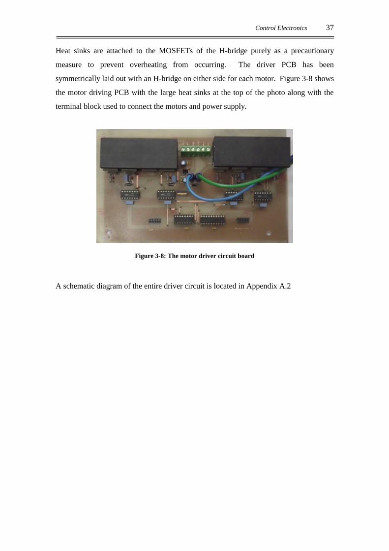
Heat sinks are attached to the MOSFETs of the H-bridge purely as a precautionary
measure to prevent overheating from occurring. The driver PCB has been
symmetrically laid out with an H-bridge on either side for each motor. Figure 3-8 shows
the motor driving PCB with the large heat sinks at the top of the photo along with the
terminal block used to connect the motors and power supply.
Figure 3-8: The motor driver circuit board
A schematic diagram of the entire driver circuit is located in Appendix A.2

38 Design and Construction of an Autonomous Mobile Security Device
Sensing Techniques 39
4. SENSING TECHNIQUES
4.1 OVERVIEW
The sensing requirements of a large-scale security device are many. The device must be
able to navigate its surroundings accurately, while avoiding any obstacles that are in its
path. In the office environment, it is likely that many of the obstacles that MARVIN
will encounter will not be fixed, and their position may change from day to day.
MARVIN needs to be able to detect these obstacles in time for it to take evasive action
and avoid collision.
The device must be able to map its surroundings in order for it to achieve a sense of
location. It is possible to perform map-matching on the data received from the sensors,
from which the robot will be able to “recognise” its surroundings and therefore calculate
its absolute position. For MARVIN to calculate its position, information on the distance
and heading that it has travelled is required.
4.2 PROXIMITY SENSORS
Proximity sensors are used to detect the presence (or absence) of an object. MARVIN
will require such sensors to prevent collision with obstacles it may encounter in its
operating environment. The methods of sensing listed below are some of the more
common forms of proximity sensing.
4.2.1 Tactile Sensors
This detection method involves direct physical contact between the sensor and the
object detected. This contact may be executed through the use of an antennae or feeler,
or by a touch-sensitive bumper. The feeler method is comprised of a flexible feeler
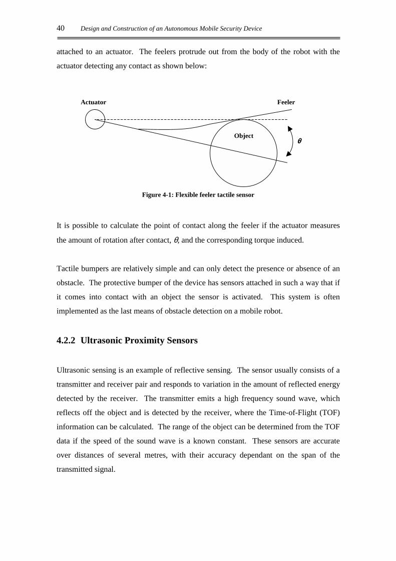
40 Design and Construction of an Autonomous Mobile Security Device
attached to an actuator. The feelers protrude out from the body of the robot with the
actuator detecting any contact as shown below:
Figure 4-1: Flexible feeler tactile sensor
It is possible to calculate the point of contact along the feeler if the actuator measures
the amount of rotation after contact, θ, and the corresponding torque induced.
Tactile bumpers are relatively simple and can only detect the presence or absence of an
obstacle. The protective bumper of the device has sensors attached in such a way that if
it comes into contact with an object the sensor is activated. This system is often
implemented as the last means of obstacle detection on a mobile robot.
4.2.2 Ultrasonic Proximity Sensors
Ultrasonic sensing is an example of reflective sensing. The sensor usually consists of a
transmitter and receiver pair and responds to variation in the amount of reflected energy
detected by the receiver. The transmitter emits a high frequency sound wave, which
reflects off the object and is detected by the receiver, where the Time-of-Flight (TOF)
information can be calculated. The range of the object can be determined from the TOF
data if the speed of the sound wave is a known constant. These sensors are accurate
over distances of several metres, with their accuracy dependant on the span of the
transmitted signal.
Actuator
Object θθθθ
Feeler
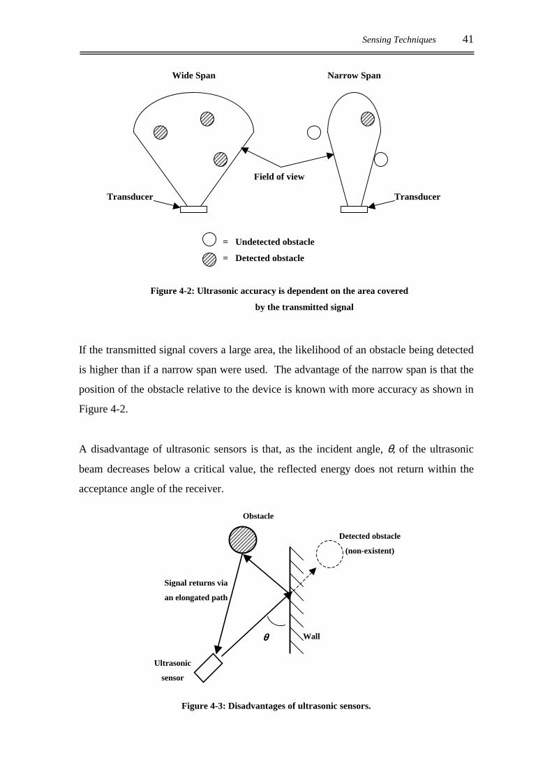
Sensing Techniques 41
Figure 4-2: Ultrasonic accuracy is dependent on the area covered
by the transmitted signal
If the transmitted signal covers a large area, the likelihood of an obstacle being detected
is higher than if a narrow span were used. The advantage of the narrow span is that the
position of the obstacle relative to the device is known with more accuracy as shown in
Figure 4-2.
A disadvantage of ultrasonic sensors is that, as the incident angle, θ, of the ultrasonic
beam decreases below a critical value, the reflected energy does not return within the
acceptance angle of the receiver.
Figure 4-3: Disadvantages of ultrasonic sensors.
= Undetected obstacle
= Detected obstacle
Wide Span Narrow Span
Transducer
Field of view
Transducer
Wall
Signal returns via
an elongated path
Obstacle
Ultrasonic
sensor
θθθθ
Detected obstacle
(non-existent)
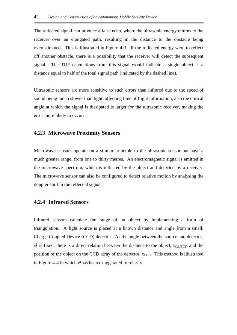
42 Design and Construction of an Autonomous Mobile Security Device
The reflected signal can produce a false echo, where the ultrasonic energy returns to the
receiver over an elongated path, resulting in the distance to the obstacle being
overestimated. This is illustrated in Figure 4-3. If the reflected energy were to reflect
off another obstacle, there is a possibility that the receiver will detect the subsequent
signal. The TOF calculations from this signal would indicate a single object at a
distance equal to half of the total signal path (indicated by the dashed line).
Ultrasonic sensors are more sensitive to such errors than infrared due to the speed of
sound being much slower than light, affecting time of flight information, also the critical
angle at which the signal is dissipated is larger for the ultrasonic receiver, making the
error more likely to occur.
4.2.3 Microwave Proximity Sensors
Microwave sensors operate on a similar principle to the ultrasonic sensor but have a
much greater range, from one to thirty metres. An electromagnetic signal is emitted in
the microwave spectrum, which is reflected by the object and detected by a receiver.
The microwave sensor can also be configured to detect relative motion by analysing the
doppler shift in the reflected signal.
4.2.4 Infrared Sensors
Infrared sensors calculate the range of an object by implementing a form of
triangulation. A light source is placed at a known distance and angle from a small,
Charge Coupled Device (CCD) detector. As the angle between the source and detector,
θ, is fixed, there is a direct relation between the distance to the object, xOBJECT, and the
position of the object on the CCD array of the detector, xCCD. This method is illustrated
in Figure 4-4 in which θ has been exaggerated for clarity.

Sensing Techniques 43
Figure 4-4: Triangulation method of range finding
4.3 MARVIN’S PROXIMITY SENSORS
Infrared sensors were chosen to implement the proximity sensing on MARVIN. They
are relatively simple to implement and are more accurate over shorter distances than
ultrasonic sensors. They also provide a form of short-range obstacle detection that is
less invasive than tactile sensors, which is desirable when the operating environment for
MARVIN is considered. Tactile sensors require precise control of the robot’s motion to
ensure that it can stop as soon as contact is detected. This form of control is not
available with the drive system employed on MARVIN.
The infrared emitter/detector (IRED) pair chosen to perform the detection from onboard
MARVIN is the Sharp GP2D12 shown in Figure 4-5, which is a Position Sensitive
Device (PSD). The emitter and receiver are in a fixed arrangement and are constructed
in single package as shown above. A small linear CCD array detector is positioned
18.75mm away from an infrared emitter and is used to compute the intensity of the
infrared reflection in the field of view. The specifications for this device state that it is
almost immune to interference from ambient light and can accurately detect objects
from 0.1m to 0.8m away.
θθθθ
Light
Source
Detector
xOBJECT
xCCD
CCD Array
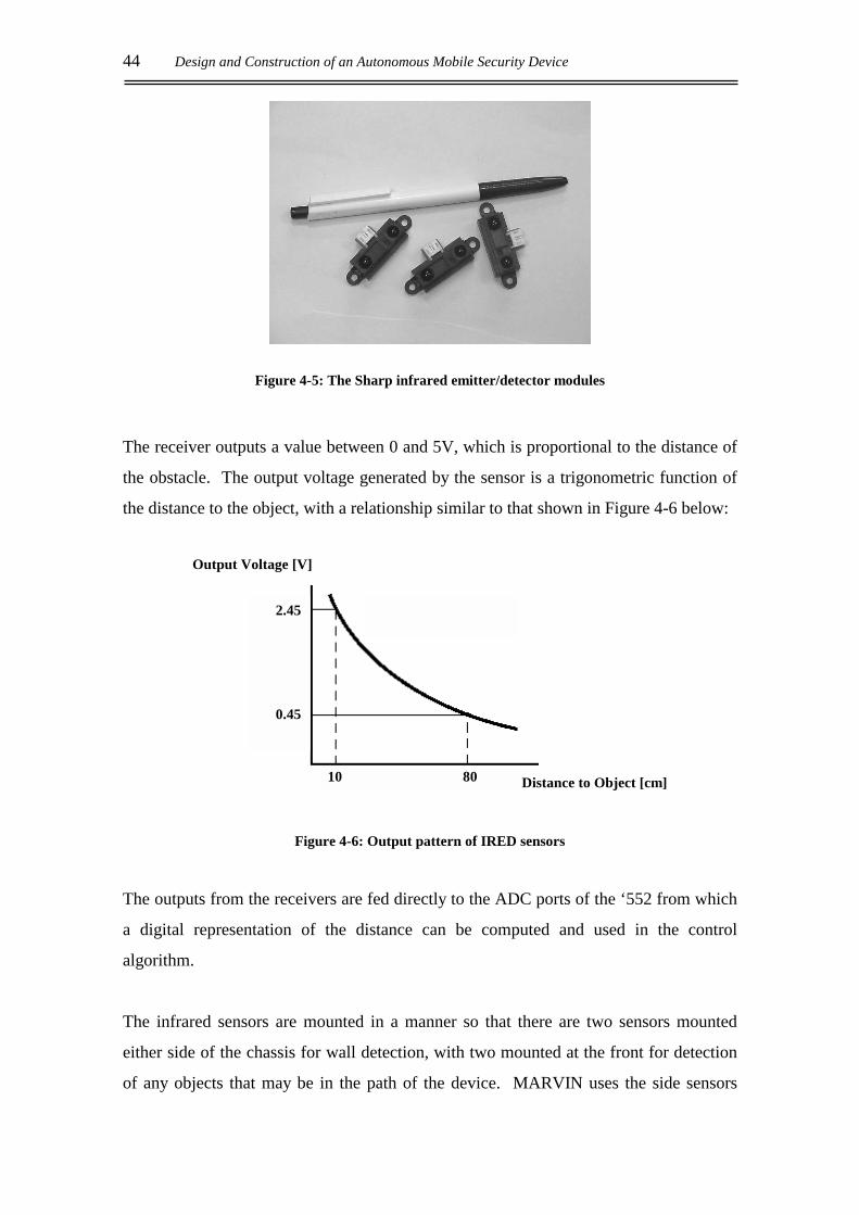
44 Design and Construction of an Autonomous Mobile Security Device
Figure 4-5: The Sharp infrared emitter/detector modules
The receiver outputs a value between 0 and 5V, which is proportional to the distance of
the obstacle. The output voltage generated by the sensor is a trigonometric function of
the distance to the object, with a relationship similar to that shown in Figure 4-6 below:
Figure 4-6: Output pattern of IRED sensors
The outputs from the receivers are fed directly to the ADC ports of the ‘552 from which
a digital representation of the distance can be computed and used in the control
algorithm.
The infrared sensors are mounted in a manner so that there are two sensors mounted
either side of the chassis for wall detection, with two mounted at the front for detection
of any objects that may be in the path of the device. MARVIN uses the side sensors
10 80
0.45
2.45
Output Voltage [V]
Distance to Object [cm]

Sensing Techniques 45
before it executes a turn to ensure there is sufficient room to complete the manoeuvre
while avoiding collision.
As MARVIN is required to operate in an office environment, the infrared detectors are
subject to a large amount of ambient light from the fluorescent lights overhead as well
as natural lighting conditions. Although the IRED sensors are largely immune to
ambient light, the various surfaces that the infrared signal will encounter will vary in
reflective efficiency, with darker surfaces absorbing more of the infrared signal emitted
from the sensor than lighter surfaces. This occurrence will only affect the range
calculations when the object is more than 35cm from the IRED sensor as shown in
Figure 4-7.
IRED Response Curves
0
20
40
60
80
100
120
140
160
0 5 10 15 20 25 30 35 40 45 50 55 60 65 70
Black surface White surface
Figure 4-7: IRED response curve (high ambient light)
The above plot shows the two extremes in reflectivity. While operating in the office
environment, the sensors will be required to reflect off a range of surfaces, from timber
to aluminium, plastic or paint of various colours. The above response curve illustrates
that the detectors will give an accurate indication of distance up to approximately 35cm
before errors from surface absorption will occur. The curve also highlights an initial
ADC Value
Distance [cm]
Accurate Operating Region
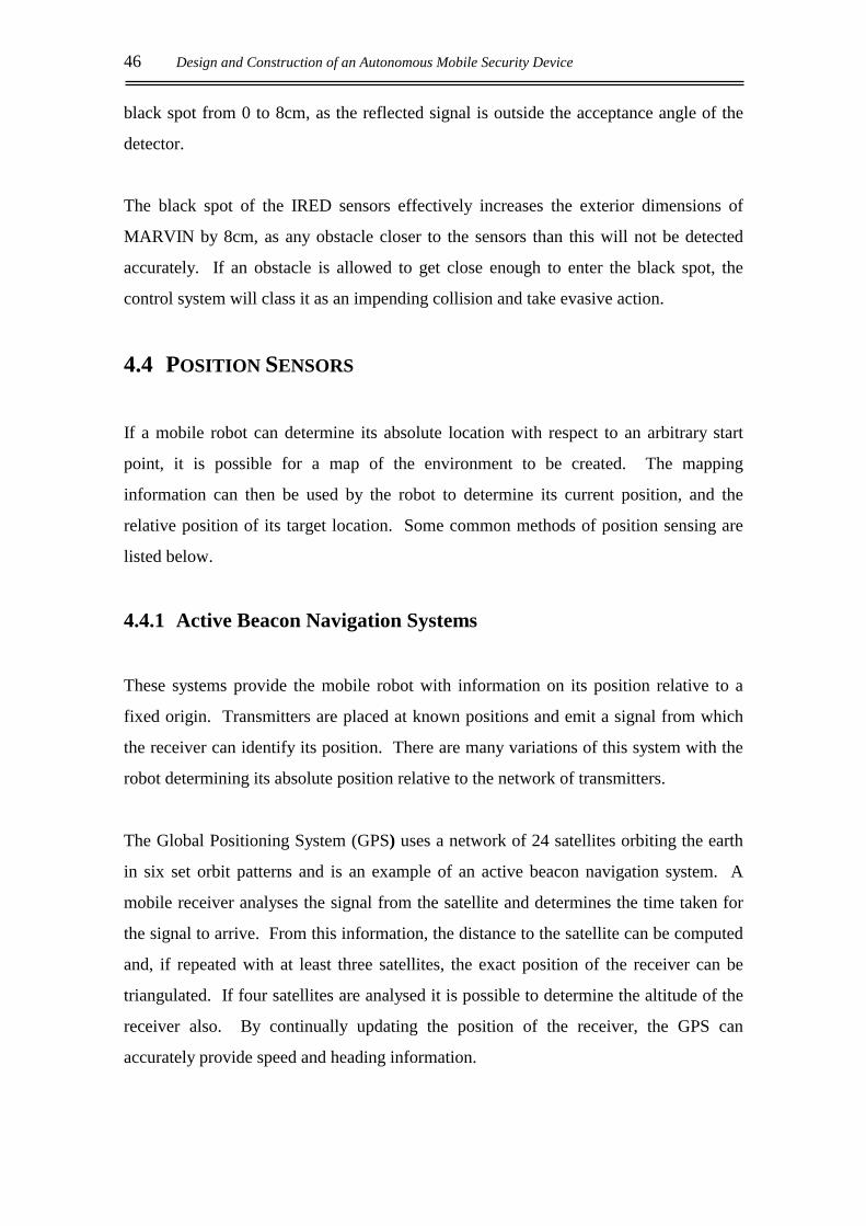
46 Design and Construction of an Autonomous Mobile Security Device
black spot from 0 to 8cm, as the reflected signal is outside the acceptance angle of the
detector.
The black spot of the IRED sensors effectively increases the exterior dimensions of
MARVIN by 8cm, as any obstacle closer to the sensors than this will not be detected
accurately. If an obstacle is allowed to get close enough to enter the black spot, the
control system will class it as an impending collision and take evasive action.
4.4 POSITION SENSORS
If a mobile robot can determine its absolute location with respect to an arbitrary start
point, it is possible for a map of the environment to be created. The mapping
information can then be used by the robot to determine its current position, and the
relative position of its target location. Some common methods of position sensing are
listed below.
4.4.1 Active Beacon Navigation Systems
These systems provide the mobile robot with information on its position relative to a
fixed origin. Transmitters are placed at known positions and emit a signal from which
the receiver can identify its position. There are many variations of this system with the
robot determining its absolute position relative to the network of transmitters.
The Global Positioning System (GPS) uses a network of 24 satellites orbiting the earth
in six set orbit patterns and is an example of an active beacon navigation system. A
mobile receiver analyses the signal from the satellite and determines the time taken for
the signal to arrive. From this information, the distance to the satellite can be computed
and, if repeated with at least three satellites, the exact position of the receiver can be
triangulated. If four satellites are analysed it is possible to determine the altitude of the
receiver also. By continually updating the position of the receiver, the GPS can
accurately provide speed and heading information.

Sensing Techniques 47
GPS acquisition software is readily available and can provide real-time analysis of GPS
position, course and velocity. It is possible to construct and store a reference map of the
operating environment for the mobile robot, which can then be used to efficiently
navigate its surroundings and achieve its target destination.
4.4.2 Landmark Navigation
This form of position sensing employs a network of set features in the operating
environment of the robot to guide it toward the target destination. The landmarks used
in the navigation of the device can either be distinctive natural features, or artificial
landmarks, specifically placed to assist the robot in navigation. These systems can
remove an aspect of the robot’s autonomy due to the external feedback control it
provides.
Landmark navigation is the primary guidance system in Automated Guided Vehicles
(AGV), which follow a network of artificial landmarks to their target destination, such
as the large mobile robot developed by the University of Canterbury, in Christchurch.
As the landmarks are mainly used for obstacle avoidance, this system does not give an
accurate representation of the robots’ location with respect to its starting point.
4.4.3 Laser Range-Finding
The Laser Range Finder uses a similar method of triangulation to that used in the IRED
sensors. A laser line is produced that is analysed by a CCD camera, this takes a
“snapshot” of the line against the robot’s surroundings. The position of the line on the
CCD array determines the distance to the obstacles in the frame as is done with the
IRED method.
Laser Range Finding has the advantage of being an independent unit and does not
require a system of beacons or landmarks to be constructed in the operating
environment. The range finding assembly will not have the additional reception
concerns, which can render an active beacon system useless should the signal from the
beacons be interrupted. These factors add to the versatility of the range finding system.
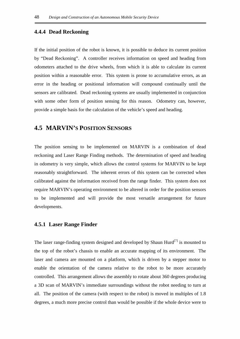
48 Design and Construction of an Autonomous Mobile Security Device
4.4.4 Dead Reckoning
If the initial position of the robot is known, it is possible to deduce its current position
by “Dead Reckoning”. A controller receives information on speed and heading from
odometers attached to the drive wheels, from which it is able to calculate its current
position within a reasonable error. This system is prone to accumulative errors, as an
error in the heading or positional information will compound continually until the
sensors are calibrated. Dead reckoning systems are usually implemented in conjunction
with some other form of position sensing for this reason. Odometry can, however,
provide a simple basis for the calculation of the vehicle’s speed and heading.
4.5 MARVIN’S POSITION SENSORS
The position sensing to be implemented on MARVIN is a combination of dead
reckoning and Laser Range Finding methods. The determination of speed and heading
in odometry is very simple, which allows the control systems for MARVIN to be kept
reasonably straightforward. The inherent errors of this system can be corrected when
calibrated against the information received from the range finder. This system does not
require MARVIN’s operating environment to be altered in order for the position sensors
to be implemented and will provide the most versatile arrangement for future
developments.
4.5.1 Laser Range Finder
The laser range-finding system designed and developed by Shaun Hurd[7] is mounted to
the top of the robot’s chassis to enable an accurate mapping of its environment. The
laser and camera are mounted on a platform, which is driven by a stepper motor to
enable the orientation of the camera relative to the robot to be more accurately
controlled. This arrangement allows the assembly to rotate about 360 degrees producing
a 3D scan of MARVIN’s immediate surroundings without the robot needing to turn at
all. The position of the camera (with respect to the robot) is moved in multiples of 1.8
degrees, a much more precise control than would be possible if the whole device were to

Sensing Techniques 49
be moved. The resolution of the stepper motor allows for 200 scans of the robot’s
environment to be made per revolution of the range finding assembly.
Figure 4-8 illustrates the laser range finding equipment used during experimental
testing. A computer screen is used to monitor the image being processed by the range
finder, the power supply is used for the stepper motor and laser, with the floppy and CD
drives used to move data for further analysis. When the range finder is mounted to the
security robot these peripherals are omitted.
Figure 4-8: The laser range finding assembly
where: A = Celeron 533MHz processor and motherboard with 64MB of RAM
B = Imagenation PX-610A frame-grabber
C = 8Gb hard-drive
D = Pulnix TM-7645I interlacing CCD Camera
E = Class IIIa 633nm laser with small cylindrical lens
F = Stepper motor driver circuitry
G = 23LM-C304-14 Miniangle Stepper motor
D
E
B
A
F
C
G
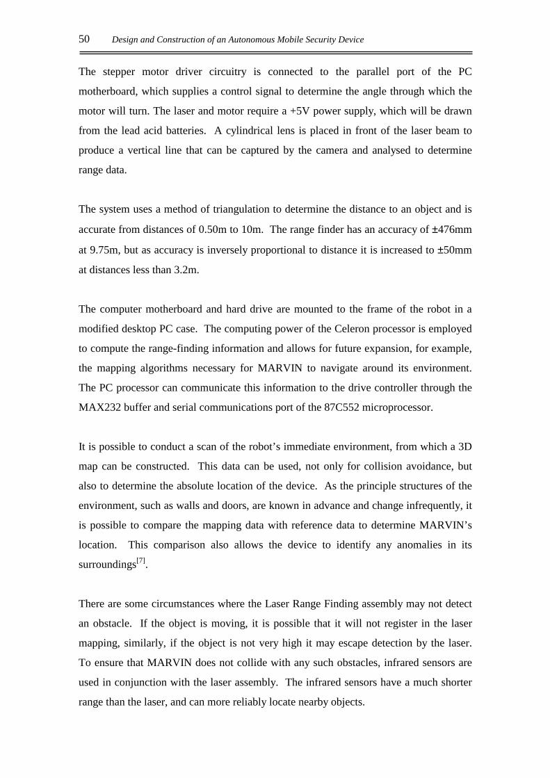
50 Design and Construction of an Autonomous Mobile Security Device
The stepper motor driver circuitry is connected to the parallel port of the PC
motherboard, which supplies a control signal to determine the angle through which the
motor will turn. The laser and motor require a +5V power supply, which will be drawn
from the lead acid batteries. A cylindrical lens is placed in front of the laser beam to
produce a vertical line that can be captured by the camera and analysed to determine
range data.
The system uses a method of triangulation to determine the distance to an object and is
accurate from distances of 0.50m to 10m. The range finder has an accuracy of ±476mm
at 9.75m, but as accuracy is inversely proportional to distance it is increased to ±50mm
at distances less than 3.2m.
The computer motherboard and hard drive are mounted to the frame of the robot in a
modified desktop PC case. The computing power of the Celeron processor is employed
to compute the range-finding information and allows for future expansion, for example,
the mapping algorithms necessary for MARVIN to navigate around its environment.
The PC processor can communicate this information to the drive controller through the
MAX232 buffer and serial communications port of the 87C552 microprocessor.
It is possible to conduct a scan of the robot’s immediate environment, from which a 3D
map can be constructed. This data can be used, not only for collision avoidance, but
also to determine the absolute location of the device. As the principle structures of the
environment, such as walls and doors, are known in advance and change infrequently, it
is possible to compare the mapping data with reference data to determine MARVIN’s
location. This comparison also allows the device to identify any anomalies in its
surroundings[7].
There are some circumstances where the Laser Range Finding assembly may not detect
an obstacle. If the object is moving, it is possible that it will not register in the laser
mapping, similarly, if the object is not very high it may escape detection by the laser.
To ensure that MARVIN does not collide with any such obstacles, infrared sensors are
used in conjunction with the laser assembly. The infrared sensors have a much shorter
range than the laser, and can more reliably locate nearby objects.

Sensing Techniques 51
4.5.2 Odometry
The odometry system is implemented with the Hewlett Packard HEDS 9100 incremental
optical encoders combined with the HEDS-5120 code wheel. The number of pulses
detected over a predefined period of time allows the speed of the driving wheel to be
determined. By comparing the information received from the encoders of the left and
right wheels, it is also possible to compute the orientation of the robot with respect to
the origin. The HEDS 5120 code wheel is a metal wheel with a resolution of 512 slots
per revolution. As the drive system has a reduction ratio of 51.56:1 (from Equation [2-
1]), the encoder will produce 26400 pulses per revolution of the wheel. The
circumference of the driving wheels is CR.L = 1052.4 mm, therefore the resolution
provided by the odometers is 25 pulses per millimetre.
The optical encoder module has an emitter/detector pair arranged in a presence sensing
arrangement with the code wheel in between the two. Whenever a slot passes between
the pair, the photo-detector receives the signal from the emitter and the module will
output +5V until the wheel cuts the signal again as illustrated in Figure 4-9.
Figure 4-9: Workings of the optical encoder
The HEDS 9100 encoder module produces two signals in quadrature (90 degrees out of
phase with each other) to enable the determination of direction. Only one of these
channels is implemented on MARVIN as the physical characteristics of the drive system
provide that the direction of the driving wheel is set by the microcontroller alone, due to
the physical braking system that has been implemented.
Light Source(emitter)
Code Wheel
Photo-detector

52 Design and Construction of an Autonomous Mobile Security Device
The encoder module and code wheel are mounted to the back of the motor as shown in
Figure 4-10.
Figure 4-10: Encoder module and code wheel assembly
Dead reckoning systems such as this are susceptible to a variety of odometry errors both
systematic and non-systematic. Systematic errors include:
• Unequal wheel diameters
• Discrepancies between nominal and actual wheel diameters
• Discrepancies between nominal and actual wheelbases
• Misaligned wheels
Non-systematic errors include:
• Uneven floor
• Wheel slippage
Systematic errors accumulate constantly and are the major contributor to odometric
error. Non-systematic errors are more likely to be a “one-off” unpredictable occurrence
and as such they are much more difficult to reduce in the control theory.
Sensing Techniques 53
4.6 MEASUREMENT OF ODOMETRY ERRORS
Unequal wheel diameters and wheelbase discrepancies cause the two fundamental
systematic errors produced by odometry. The former will cause the vehicle to travel in a
curved path when the controller intends a straight line, while the latter will cause a
heading error whenever the robot executes a turn. The wheelbase of the vehicle
determines how far each drive wheel must travel (in opposite directions) in order to
achieve a 90 degree turn.
To compensate for the systematic errors induced by odometry sensing it is necessary to
calculate the magnitude that each component contributes to the total error. The “Bi-
directional Square-path Experiment”, also know as the “University of Michigan
Benchmark”[4] (UMBmark), highlights the error caused by an inaccurate wheelbase, eb
and unequal wheel diameters, ed. In this test, the robot is programmed to travel a square
path comprising four straight line segments and four 90 degree turns, theoretically
returning to its initial position. The path is completed in both clockwise and
anticlockwise directions, with the final position of the device in relation to the origin
(positional error) recorded for each direction. The experiment is run at least five times
in order to generate a sufficient data set for analysis. The error in orientation is not
noted as it is directly proportional to the positional errors and so is automatically
accounted for.
When the results from the clockwise and anticlockwise paths are plotted they form two
distinct groupings as shown in Figure 4-11. These data values are averaged so as to
reduce the random effect of non-systematic errors on the trial.

54 Design and Construction of an Autonomous Mobile Security Device
Example of Results Obtained from running UMBmark
-250
-200
-150
-100
-50
0
50
100
150
0 50 100 150 200 250
Figure 4-11: Results from running UMBmark
The average for each direction is found as the sum of all the values divided by the
number of data points:
∑ =
= n
i icwcw exn
x1
1 Eqn. [4-1]
∑ =
= n
i icwcw eyn
y1
1 Eqn. [4-2]
where cwx , =cwy average value of x and y components for clockwise direction
icwex , =icwey ith x and y component of clockwise error
=n total number of data points
A reference vector is generated that defines the average offset from the origin by
Equation [4-3]:
22cwcwcw yxr += Eqn. [4-3]
where =cwr clockwise reference vector
Y [mm]
X [mm]
Anti-clockwise
grouping
Clockwise
grouping
racw
rcw
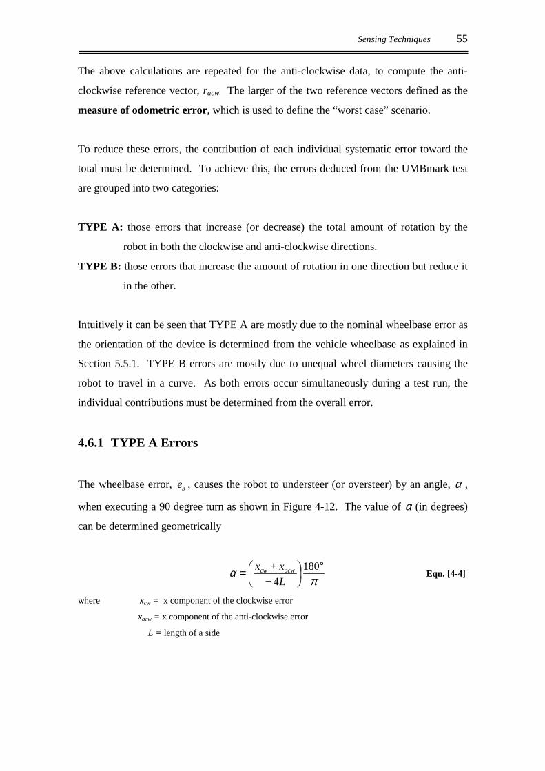
Sensing Techniques 55
The above calculations are repeated for the anti-clockwise data, to compute the anti-
clockwise reference vector, racw. The larger of the two reference vectors defined as the
measure of odometric error, which is used to define the “worst case” scenario.
To reduce these errors, the contribution of each individual systematic error toward the
total must be determined. To achieve this, the errors deduced from the UMBmark test
are grouped into two categories:
TYPE A: those errors that increase (or decrease) the total amount of rotation by the
robot in both the clockwise and anti-clockwise directions.
TYPE B: those errors that increase the amount of rotation in one direction but reduce it
in the other.
Intuitively it can be seen that TYPE A are mostly due to the nominal wheelbase error as
the orientation of the device is determined from the vehicle wheelbase as explained in
Section 5.5.1. TYPE B errors are mostly due to unequal wheel diameters causing the
robot to travel in a curve. As both errors occur simultaneously during a test run, the
individual contributions must be determined from the overall error.
4.6.1 TYPE A Errors
The wheelbase error, be , causes the robot to understeer (or oversteer) by an angle, α ,
when executing a 90 degree turn as shown in Figure 4-12. The value of α (in degrees)
can be determined geometrically
π
α °
−+= 1804L
xx acwcw Eqn. [4-4]
where xcw = x component of the clockwise error
xacw = x component of the anti-clockwise error
L = length of a side
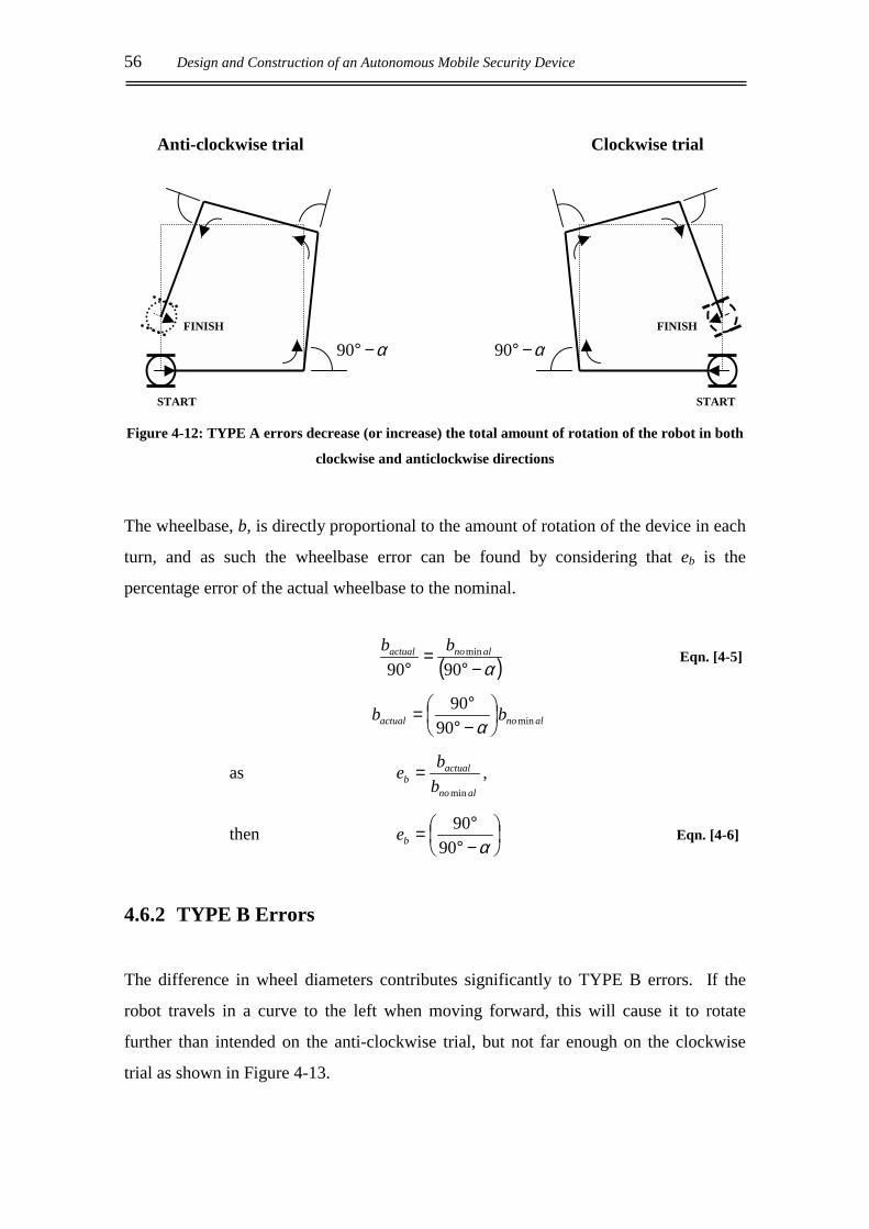
56 Design and Construction of an Autonomous Mobile Security Device
Anti-clockwise trial Clockwise trial
FINISH FINISH
α−°90 α−°90
START START
Figure 4-12: TYPE A errors decrease (or increase) the total amount of rotation of the robot in both
clockwise and anticlockwise directions
The wheelbase, b, is directly proportional to the amount of rotation of the device in each
turn, and as such the wheelbase error can be found by considering that eb is the
percentage error of the actual wheelbase to the nominal.
( )α−°=
° 9090min alnoactual bb Eqn. [4-5]
alnoactual bb min9090
−°°=α
as alno
actualb b
bemin
= ,
then
−°°=α90
90be Eqn. [4-6]
4.6.2 TYPE B Errors
The difference in wheel diameters contributes significantly to TYPE B errors. If the
robot travels in a curve to the left when moving forward, this will cause it to rotate
further than intended on the anti-clockwise trial, but not far enough on the clockwise
trial as shown in Figure 4-13.
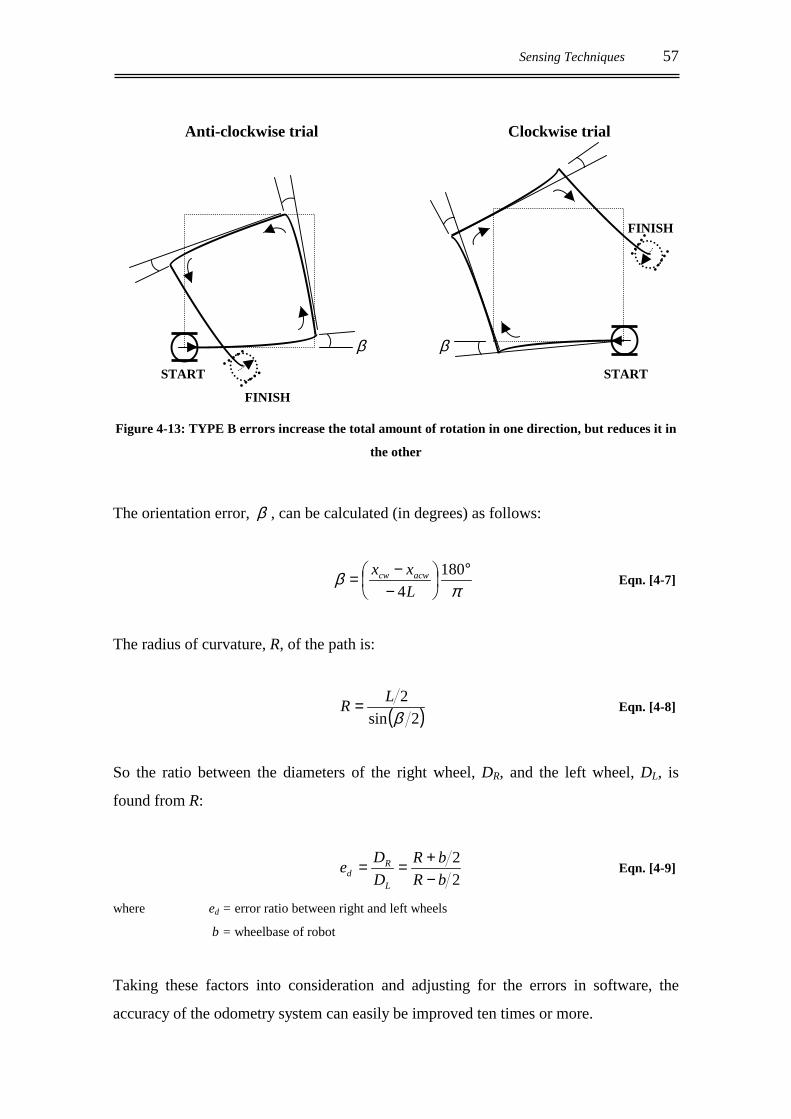
Sensing Techniques 57
Anti-clockwise trial Clockwise trial
FINISH
β β
START START
FINISH
Figure 4-13: TYPE B errors increase the total amount of rotation in one direction, but reduces it in
the other
The orientation error, β , can be calculated (in degrees) as follows:
π
β °
−−= 1804L
xx acwcw Eqn. [4-7]
The radius of curvature, R, of the path is:
( )2sin2
βLR = Eqn. [4-8]
So the ratio between the diameters of the right wheel, DR, and the left wheel, DL, is
found from R:
22
bRbR
DDe
L
Rd −
+== Eqn. [4-9]
where ed = error ratio between right and left wheels
b = wheelbase of robot
Taking these factors into consideration and adjusting for the errors in software, the
accuracy of the odometry system can easily be improved ten times or more.

58 Design and Construction of an Autonomous Mobile Security Device
4.7 REDUCTION OF ODOMETRIC ERRORS
There are several factors that influence the accuracy of odometry readings for position
sensing. The following are guidelines that should be considered when designing a
mobile robot.
• Castors should bear as little weight as possible, especially when the robot is
accelerating or decelerating. If the centre of gravity is kept as low as practically
possible, the drive wheels are less likely to lose traction under load and cause errors.
• If pneumatic tyres are used, they should be kept with ample pressure, reducing their
compressibility and hence the chance of the diameter being reduced or becoming
unequal.
• The wheelbase of a differential drive robot should be kept to a minimum. The
probability of orientation errors occurring is higher with a large wheelbase than with
smaller wheelbases. The smaller the wheelbase, the higher the torque required to
execute a turn and as such, the size can be limited by the power of the driving
motors.
• If the odometers are mounted to the driving wheels then wheel slippage must be
avoided. If the driving motors are powerful enough to cause the wheels to lose
traction under acceleration, then the acceleration of the device should be limited to
ensure that this does not occur.
• The odometry equipment should be of a suitable accuracy. If the odometers are
mounted directly to the driving wheels will the resolution provided be sufficient for
accurate control? The odometers on MARVIN are mounted to the driving motors,
taking advantage of the reduction ratio of the gear train to increase the resolution.

Motor Theory and Control 59
5. MOTOR THEORY AND CONTROL
The motors used in the drive train of the robot are 24V DC motors, originally intended
for use in an electric wheelchair. They are manufactured by Dynamic Mobility in
Christchurch and have a single worm gearbox incorporated in the motor housing.
5.1 MODEL OF THE DC MOTOR
A basic model of a DC motor can be considered as a large number of current carrying
wire loops in the presence of a magnetic field. The magnetic field generated between
the two poles of a permanent magnet and creates a force, F(t), which acts on each of the
current loops according to the Lorentz law (Equation [5-1]), in the direction determined
by the “Right-hand rule”.
F(t) = B l I(t) Eqn. [5-1] where B = magnetic field flux density
l = length of wire loop
I(t) = current flowing in wire loop
The right-hand rule states that if the fingers of the right hand are pointed in the direction
of the magnetic field with the thumb in the direction of current flow, the palm will be
facing in the direction of the force. The opposite sides of the wire loop therefore have
forces acting on them in opposite directions, inducing a torque as shown in Figure 5-1.
The torque generated increases linearly with current by the relationship:
T = Kt I(t) Eqn. [5-2] where Kt = the torque constant
T = induced torque

60 Design and Construction of an Autonomous Mobile Security Device
Figure 5-1: An illustration of the torque generated on the motor shaft
due to the force acting on the armature
As the motor shaft rotates, the motion of the loop through the magnetic field causes a
voltage to be induced which opposes the motor current. This voltage is called the back
emf, eb. The multiple coils of the motor result in a smooth back emf voltage, which is
dependent only on the speed of the armature.
eb = Ke ωa Eqn. [5-3] where Ke = back emf constant
ωa = angular velocity of armature
Ke is numerically equivalent to the torque constant, Kt, when SI units are used. When
the current is kept constant, the armature voltage consists of the back emf and the
voltage drop across the armature resistance.
baa eRie += Eqn. [5-4]
where ea = armature voltage
ia = armature current
R = armature resistance
S N
MAGNETIC FIELD
FORCE UP
FORCE DOWN CURRENT
MOTOR SHAFT

Motor Theory and Control 61
5.2 ELECTRICAL MODEL OF A DC MOTOR
A permanent magnet DC motor can be represented electrically as the following model:
Figure 5-2: Electrical model of a DC motor
Analysis of the above current loop yields the electrical equation of a DC motor:
ba
aain edt
dILIRe ++= Eqn. [5-5]
where Ra = armature resistance
Ia = motor current
L = armature winding inductance
eb = back emf voltage
If we define Jm as the combined moment of inertia for the motor and load, and allowing
for the friction torque of the system, then by Newton’s second law we can state that:
fm
mm Tdt
dJT += ω Eqn. [5-6]
where Tm = motor torque
ωm = rotation speed at shaft
Tf = fiction torque
The friction torque component is dependent on angular velocity and can be defined as:
mmf BT ω= Eqn. [5-7]
where Bm = the viscous friction
Ra L
M ea Ia
eb

62 Design and Construction of an Autonomous Mobile Security Device
5.3 MOTOR CONTROL
In order to control the motors of the robot more efficiently it is necessary to calculate
their transfer function. To achieve this the equations developed earlier in the chapter
must be converted from the time to the frequency domain (s-domain). The following
equations are produced:
From Eqn [5-2]:
( ) ( )sIKsT atm = Eqn. [5-8]
From Eqn [5-3]:
( ) ( )sKsE meb Ω= Eqn. [5-9]
From Eqn [5-5]:
( ) ( ) ( ) ( )sEsRIsLsIsE baaa ++=
( ) ( ) ( )[ ]
+−=
LsRsEsEsI baa
1 Eqn. [5-10]
By rearranging these equations and substituting for Ia(s), the following velocity transfer
function is found:
( )( ) ( ) 2sRBsRBKKRB
KsEs
emmemmtem
t
a
m
ττττ ++++=Ω Eqn. [5-11]
This formula can be further simplified if the armature inductance is small or the motor
inertia is large (as is the case with MARVIN), in which case the assumption that τe = 0
can be made. The simplified version of the velocity transfer function is:
( )( ) s
KsEs
s
s
a
m
τ+=Ω
1 Eqn. [5-12]
where =+
=tem
ts KKRB
KK simplified gain
=+
=tem
ms KKRB
RJτ simplified time constant

Motor Theory and Control 63
as m
mm B
J=τ
The planetary gear head attached to the motor’s shaft acts as a speed reducer, increasing
the torque of the system. The reducer changes the mechanical resistance of the load so
that the motor experiences less friction torque, but the added load on the shaft will slow
the motor’s response, increasing the mechanical time constant, τm. If N1 is the number
of teeth on the gear head, with N2 the number of teeth on the wheel, then the speed of
the load (or wheel) can be computed as:
mw NN ωω
=
2
1 Eqn. [5-13]
Therefore the torque seen at the wheel is:
mw TNNT
=
1
2 Eqn. [5-14]
where ωw = wheel speed
Tw = wheel torque
The total inertia and friction combine to produce the mechanical time constant for the
system:
LmT JNNJJ
2
2
1
+= Eqn. [5-15]
LmT BNNBB
2
2
1
+= Eqn. [5-16]
T
TT B
J=τ Eqn. [5-17]
where JT = total inertia
BT = total friction
τT = total torque
JL = load inertia
BL = load friction

64 Design and Construction of an Autonomous Mobile Security Device
The block diagram for the motor, gearing and load is illustrated in Figure 5-3 below:
Figure 5-3: Block diagram of the DC motor
where ea = armature voltage
eb = back emf
Ia = motor current
Tm = motor torque
Ωm = shaft speed
ΩL = load speed
θL = load position
The transfer function for the entire system can be derived from Equation [5-11] if Bm is
replaced with BT, Jm with JT and τm with τL and the gearing is accounted for by
multiplying by N1/N2.
( )( ) ( )
++++=Ω
2
12 N
NsRBsRBKKRB
KsEs
eTTeTTteT
t
a
m
ττττ
Eqn. [5-18]
5.4 MOTOR PARAMETERS
The specifications of the motors used on MARVIN need to be calculated experimentally
as the manufacturer’s data sheets are not available. The armature resistance of the
motor is measured with a multi-meter across the terminals and is R = 1.5 Ω. The
inductance, L, of the motor is found to be 0.45 mH.
LsR +1
sJB TT +
1Kt
Ke
s1
+
_
∑ea
eb
Ia Tm ΩΩΩΩm θθθθL
2
1
NN ΩΩΩΩL
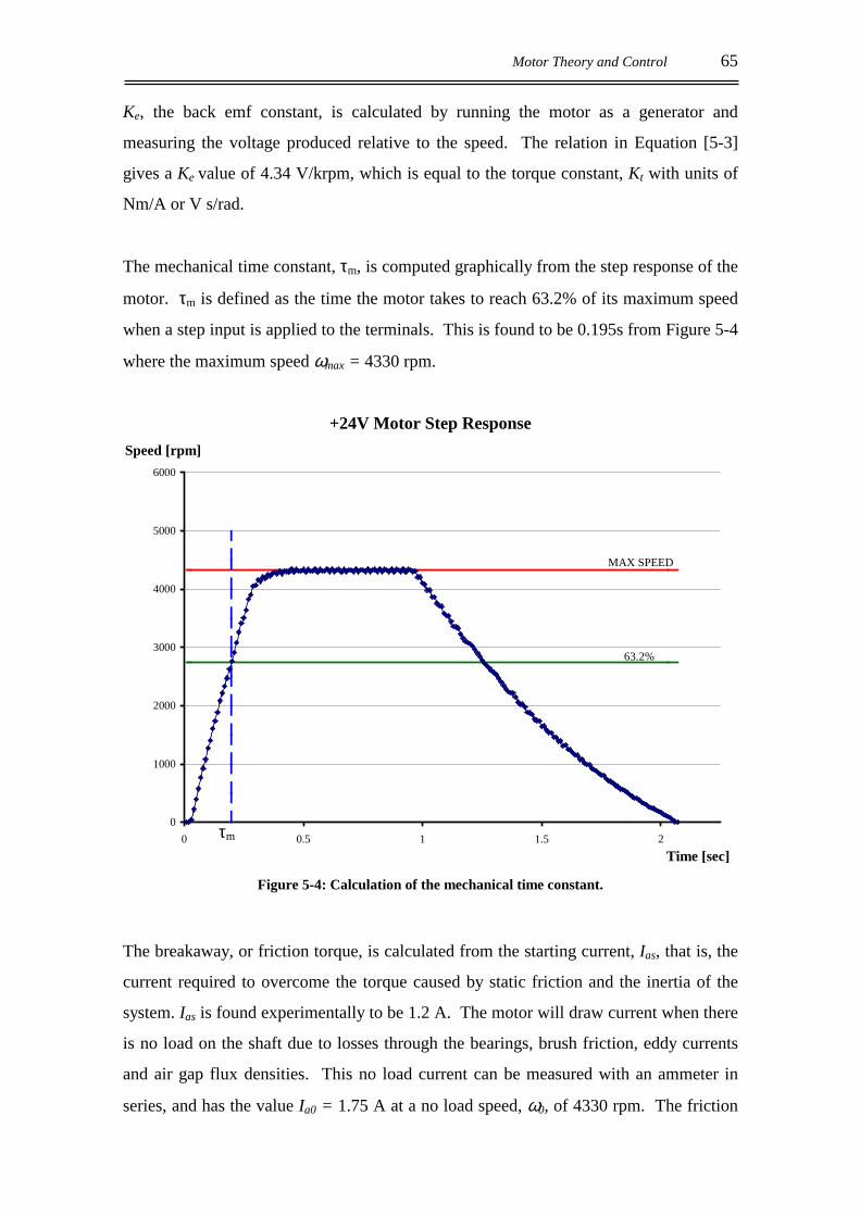
Motor Theory and Control 65
Ke, the back emf constant, is calculated by running the motor as a generator and
measuring the voltage produced relative to the speed. The relation in Equation [5-3]
gives a Ke value of 4.34 V/krpm, which is equal to the torque constant, Kt with units of
Nm/A or V s/rad.
The mechanical time constant, τm, is computed graphically from the step response of the
motor. τm is defined as the time the motor takes to reach 63.2% of its maximum speed
when a step input is applied to the terminals. This is found to be 0.195s from Figure 5-4
where the maximum speed ωmax = 4330 rpm.
+24V Motor Step Response
0
1000
2000
3000
4000
5000
6000
0 0.5 1 1.5 2
Figure 5-4: Calculation of the mechanical time constant.
The breakaway, or friction torque, is calculated from the starting current, Ias, that is, the
current required to overcome the torque caused by static friction and the inertia of the
system. Ias is found experimentally to be 1.2 A. The motor will draw current when there
is no load on the shaft due to losses through the bearings, brush friction, eddy currents
and air gap flux densities. This no load current can be measured with an ammeter in
series, and has the value Ia0 = 1.75 A at a no load speed, ω0, of 4330 rpm. The friction
τm
MAX SPEED
63.2%
Time [sec]
Speed [rpm]
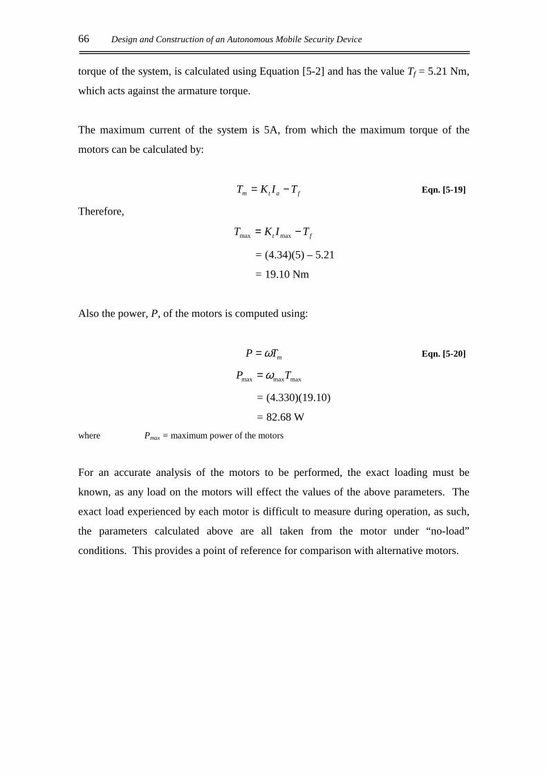
66 Design and Construction of an Autonomous Mobile Security Device
torque of the system, is calculated using Equation [5-2] and has the value Tf = 5.21 Nm,
which acts against the armature torque.
The maximum current of the system is 5A, from which the maximum torque of the
motors can be calculated by:
fatm TIKT −= Eqn. [5-19]
Therefore,
ft TIKT −= maxmax
= (4.34)(5) – 5.21
= 19.10 Nm
Also the power, P, of the motors is computed using:
mTP ω= Eqn. [5-20]
maxmaxmax TP ω=
= (4.330)(19.10)
= 82.68 W where Pmax = maximum power of the motors
For an accurate analysis of the motors to be performed, the exact loading must be
known, as any load on the motors will effect the values of the above parameters. The
exact load experienced by each motor is difficult to measure during operation, as such,
the parameters calculated above are all taken from the motor under “no-load”
conditions. This provides a point of reference for comparison with alternative motors.
Motor Theory and Control 67
5.5 PHYSICAL MOTION OF THE ROBOT
5.5.1 Turning
In the majority of circumstances MARVIN will encounter in its environment, the
required turning angle is a multiple of 90°. Once the robot can execute a 90° turn it can
then turn left, right and turn to face the direction from which it has come. To achieve
the turn, each of the driving wheels must travel a distance equal to one quarter of the
circumference of the robot, Crob, in opposite directions as illustrated in Figure 5-5.
The circumference Crob is calculated from the circle
with a diameter equal to the wheelbase of the robot,
bnominal. To convert this distance into a specific number
of motor revolutions, the circumference of the driving
wheels must be calculated and used along with the total
reduction ratio, N, of the motor gearing, as calculated in
Equation [2-1].
The diameter of the driving wheels, DR,L = 335mm, so the circumferences of the wheels,
CR,L = 1052.4 mm. Therefore:
1 revmotor = CR,L / N Eqn. [5-21]
= 20.41mm of travel for the robot
As there are 512 pulses on the encoder module per motor revolution, the resolution of
the odometers is 0.04mm per pulse.
Figure 5-5: Each driving
wheel must travel Crob / 4 to
turn 90°°°°.

68 Design and Construction of an Autonomous Mobile Security Device
5.5.2 Acceleration
Acceleration profile
Figure 5-6: Required acceleration profile to reach a target position
In order for MARVIN to travel in a straight line to a target position, it is necessary for it
to follow an acceleration profile as illustrated in Figure 5-6 above. The most efficient
profile requires the robot to accelerate to a desired speed, maintain that speed for a
required distance, and then decelerate to a stop at the specified target position.
The acceleration of the device to a desired speed follows a complex curve, but if the step
responses of are analysed some simplifications can be made. The time taken for
MARVIN to reach its maximum speed varies from 0.56 to 1.36 seconds depending on
the set PWM value. In this time the robot could cover a distance between 20 and 90 cm.
Due to the physical characteristics of the device and the maximum power that the
driving motors can provide, wheel slippage is not a limiting factor of its acceleration.
Figure 5-7 shows the velocity profiles generated by the mechatron in response to a
variety of step inputs. This clearly illustrates the motion of the robot under acceleration,
as it reaches a steady-state speed dependant on the input PWM value. The deceleration
of the device is purely frictional, achieved by removing power from the driving motors
and allowing it to coast to a stop. Irrespective of the set PWM value, the robot
decelerates at the same constant rate, Ao.
Acceleration Constant Speed Deceleration
velocity
time target

Motor Theory and Control 69
Step responses for various PWM values
0.0
0.2
0.4
0.6
0.8
1.0
1.2
1.4
0.0 1.0 2.0 3.0 4.0 5.0 6.0
PWM = 0x50 PWM = 0x40 PWM = 0x30 PWM = 0x20
Figure 5-7: Robot step responses for various PWM values
5.5.3 Braking
This deceleration constant is calculated from the above graph to be, Ao = -0.445m/s2. If
MARVIN is travelling in a straight line at the maximum velocity of vmax = 1.32m/s and
decelerates to a stop, the distance covered in doing so is:
o
dec Avt max−= Eqn. [5-22]
= -1.32 / -0.445
= 2.97 s
2max 5.0 decodecdec tAtvx += Eqn. [5-23]
= 1.32(2.97) + 0.5(-0.445)(2.97)2
= 1.96 m
where tdec = time to decelerate to a stop
xdec = distance covered in decelerating to a stop
Speed [m/s]
Time [sec]

70 Design and Construction of an Autonomous Mobile Security Device
It is undesirable for the robot to have such a large stopping distance. IRED position
sensitive devices (PSD) have been implemented as the sensors used to detect objects
that lie in the path of the device. The variation in the reflectivity of the surfaces
MARVIN is likely to encounter in its immediate environment, limit the accuracy of
these sensors to within 0.35m (the reasons for which are explained in further detail in
Section 4.3). As the IRED sensors are used to detect obstacles in the immediate path of
the device, it is necessary for MARVIN to be able to stop from full speed within 0.35m
in order for it to avoid collision with possible hazards.
To achieve this there are two options, the first is to reduce the maximum speed of the
robot thus reducing the distance taken to stop. This method reduces the performance of
the device and is also impractical as the required value for vmax would be in the region of
0.5m/s, which is far below the required speed in the initial design specifications. The
second is to introduce a form of braking to increase the deceleration constant of the
robot. This is the more desirable option, as it does not compromise performance to the
same extent.
There are many different ways in which the braking of a dynamic system can be
implemented:
• Regenerative braking utilises the current generated by the decelerating motor, by
feeding it back into the system where it can be used to recharge the batteries if
required.
• Dynamic braking also uses the stored mechanical energy of the motor, but instead of
returning the current to the system, the energy is dissipated as heat through braking
resistors or even through the motor itself, as a decelerating torque is temporarily
produced by the generator action of the motor.
• Mechanical friction braking is the simplest of the variations to implement, as it
involves a slowing of the motor by physically hampering its rotation. This method
can be achieved in a number of ways.
Both the regenerative and dynamic systems can be complicated to implement and may
add additional stress to the motors. The system chosen for MARVIN is a slightly

Motor Theory and Control 71
developed version of that present on the original electric wheelchair system and is a
form of mechanical friction braking.
The system consists of an electromagnet, which is used to raise the brake pad off the
worm drive to release the brake. When the current to the magnet is removed, a strong
spring pushes the pad down onto the helical worm and, due to the gear reduction ratio of
the entire drive system, produces enough of a decelerating torque to act as an effective
brake. This system of braking is illustrated in Figure 5-8.
Figure 5-8: Mechanical brake system acting on the worm drive of the motor
In this arrangement, the electromagnet must hold the brake off the helical gear any time
the motor is being driven. The force on the brake produced by the spring is so great that
there must be at least 20V on the electromagnet’s coil before the brake is released and
the coil draws a constant current of 1.35A at 24 volts. These values highlight the
inefficiencies of this method, but the system produces a very strong brake as shown by
the increased deceleration constant, illustrated in Figure 5-11.
Motor
Electromagnet
Spring
Brake pad
Drive Shaft
Worm Drive
+24V
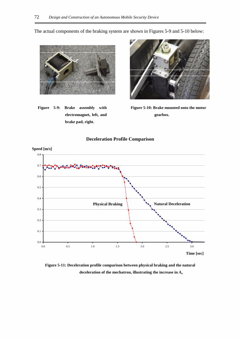
72 Design and Construction of an Autonomous Mobile Security Device
The actual components of the braking system are shown in Figures 5-9 and 5-10 below:
Deceleration Profile Comparison
0.0
0.1
0.2
0.3
0.4
0.5
0.6
0.7
0.8
0.0 0.5 1.0 1.5 2.0 2.5 3.0
Figure 5-11: Deceleration profile comparison between physical braking and the natural
deceleration of the mechatron, illustrating the increase in Ao
Speed [m/s]
Time [sec]
Natural Deceleration Physical Braking
Figure 5-9: Brake assembly with
electromagnet, left, and
brake pad, right.
Figure 5-10: Brake mounted onto the motor
gearbox.
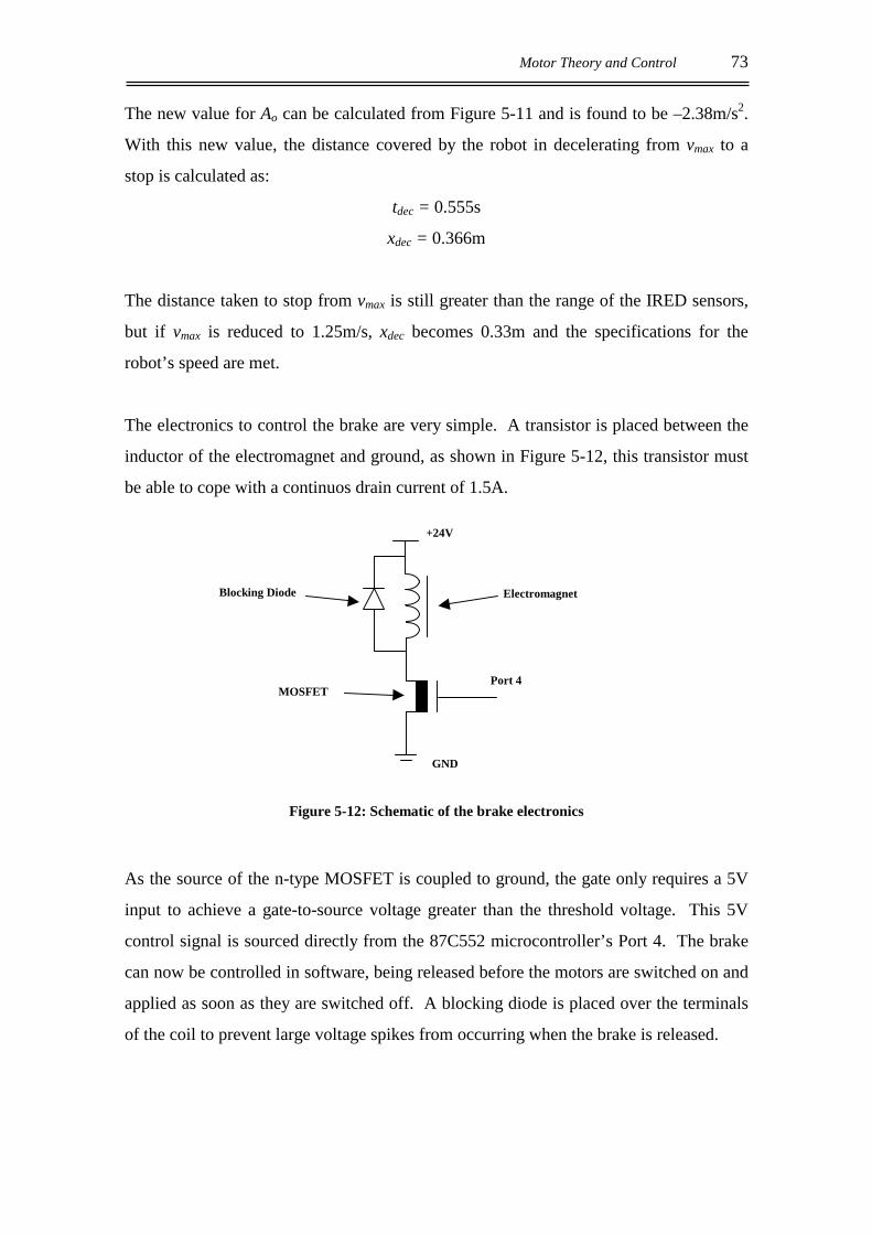
Motor Theory and Control 73
The new value for Ao can be calculated from Figure 5-11 and is found to be –2.38m/s2.
With this new value, the distance covered by the robot in decelerating from vmax to a
stop is calculated as:
tdec = 0.555s
xdec = 0.366m
The distance taken to stop from vmax is still greater than the range of the IRED sensors,
but if vmax is reduced to 1.25m/s, xdec becomes 0.33m and the specifications for the
robot’s speed are met.
The electronics to control the brake are very simple. A transistor is placed between the
inductor of the electromagnet and ground, as shown in Figure 5-12, this transistor must
be able to cope with a continuos drain current of 1.5A.
Figure 5-12: Schematic of the brake electronics
As the source of the n-type MOSFET is coupled to ground, the gate only requires a 5V
input to achieve a gate-to-source voltage greater than the threshold voltage. This 5V
control signal is sourced directly from the 87C552 microcontroller’s Port 4. The brake
can now be controlled in software, being released before the motors are switched on and
applied as soon as they are switched off. A blocking diode is placed over the terminals
of the coil to prevent large voltage spikes from occurring when the brake is released.
+24V
Port 4
GND
Electromagnet
MOSFET
Blocking Diode
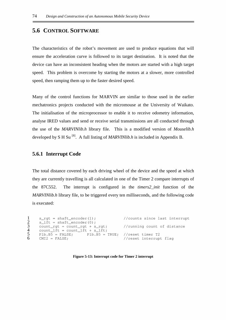
74 Design and Construction of an Autonomous Mobile Security Device
5.6 CONTROL SOFTWARE
The characteristics of the robot’s movement are used to produce equations that will
ensure the acceleration curve is followed to its target destination. It is noted that the
device can have an inconsistent heading when the motors are started with a high target
speed. This problem is overcome by starting the motors at a slower, more controlled
speed, then ramping them up to the faster desired speed.
Many of the control functions for MARVIN are similar to those used in the earlier
mechatronics projects conducted with the micromouse at the University of Waikato.
The initialisation of the microprocessor to enable it to receive odometry information,
analyse IRED values and send or receive serial transmissions are all conducted through
the use of the MARVINlib.h library file. This is a modified version of Mouselib.h
developed by S H Su [8]. A full listing of MARVINlib.h is included in Appendix B.
5.6.1 Interrupt Code
The total distance covered by each driving wheel of the device and the speed at which
they are currently travelling is all calculated in one of the Timer 2 compare interrupts of
the 87C552. The interrupt is configured in the timers2_init function of the
MARVINlib.h library file, to be triggered every ten milliseconds, and the following code
is executed:
s_rgt = shaft_encoder(1); //counts since last interrupt1 s_lft = shaft_encoder(0);2 count_rgt = count_rgt + s_rgt; //running count of distance3 count_lft = count_lft + s_lft;4 P1b.B5 = FALSE; P1b.B5 = TRUE; //reset timer T25 CMI2 = FALSE; //reset interrupt flag6
Figure 5-13: Interrupt code for Timer 2 interrupt
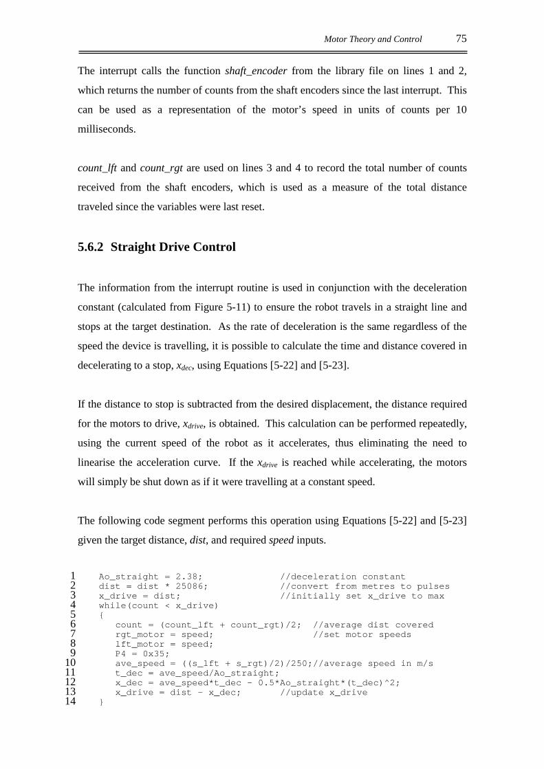
Motor Theory and Control 75
The interrupt calls the function shaft_encoder from the library file on lines 1 and 2,
which returns the number of counts from the shaft encoders since the last interrupt. This
can be used as a representation of the motor’s speed in units of counts per 10
milliseconds.
count_lft and count_rgt are used on lines 3 and 4 to record the total number of counts
received from the shaft encoders, which is used as a measure of the total distance
traveled since the variables were last reset.
5.6.2 Straight Drive Control
The information from the interrupt routine is used in conjunction with the deceleration
constant (calculated from Figure 5-11) to ensure the robot travels in a straight line and
stops at the target destination. As the rate of deceleration is the same regardless of the
speed the device is travelling, it is possible to calculate the time and distance covered in
decelerating to a stop, xdec, using Equations [5-22] and [5-23].
If the distance to stop is subtracted from the desired displacement, the distance required
for the motors to drive, xdrive, is obtained. This calculation can be performed repeatedly,
using the current speed of the robot as it accelerates, thus eliminating the need to
linearise the acceleration curve. If the xdrive is reached while accelerating, the motors
will simply be shut down as if it were travelling at a constant speed.
The following code segment performs this operation using Equations [5-22] and [5-23]
given the target distance, dist, and required speed inputs.
Ao_straight = 2.38; //deceleration constant1 dist = dist * 25086; //convert from metres to pulses2 x_drive = dist; //initially set x_drive to max3 while(count < x_drive)4 5
count = (count_lft + count_rgt)/2; //average dist covered6 rgt_motor = speed; //set motor speeds7 lft_motor = speed;8 P4 = 0x35;9 ave_speed = ((s_lft + s_rgt)/2)/250;//average speed in m/s10 t_dec = ave_speed/Ao_straight;11 x_dec = ave_speed*t_dec – 0.5*Ao_straight*(t_dec)^2;12 x_drive = dist – x_dec; //update x_drive13
14
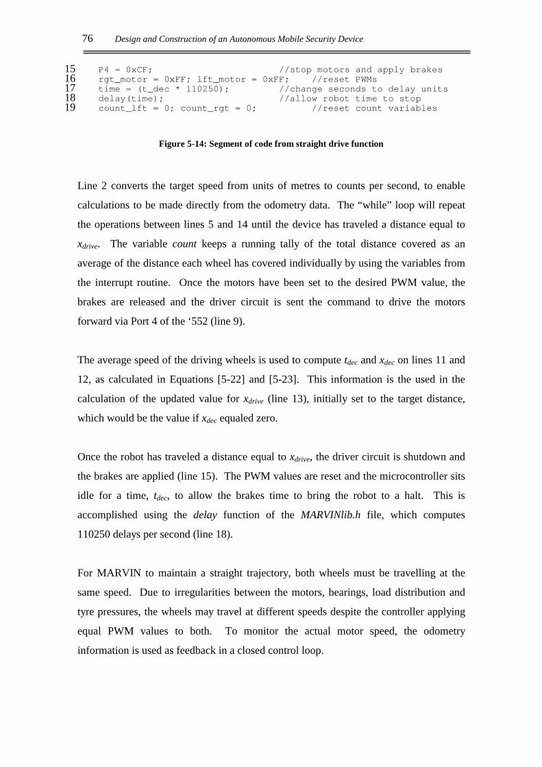
76 Design and Construction of an Autonomous Mobile Security Device
P4 = 0xCF; //stop motors and apply brakes15 rgt_motor = 0xFF; lft_motor = 0xFF; //reset PWMs16 time = (t_dec * 110250); //change seconds to delay units17 delay(time); //allow robot time to stop18 count_lft = 0; count_rgt = 0; //reset count variables19
Figure 5-14: Segment of code from straight drive function
Line 2 converts the target speed from units of metres to counts per second, to enable
calculations to be made directly from the odometry data. The “while” loop will repeat
the operations between lines 5 and 14 until the device has traveled a distance equal to
xdrive. The variable count keeps a running tally of the total distance covered as an
average of the distance each wheel has covered individually by using the variables from
the interrupt routine. Once the motors have been set to the desired PWM value, the
brakes are released and the driver circuit is sent the command to drive the motors
forward via Port 4 of the ‘552 (line 9).
The average speed of the driving wheels is used to compute tdec and xdec on lines 11 and
12, as calculated in Equations [5-22] and [5-23]. This information is the used in the
calculation of the updated value for xdrive (line 13), initially set to the target distance,
which would be the value if xdec equaled zero.
Once the robot has traveled a distance equal to xdrive, the driver circuit is shutdown and
the brakes are applied (line 15). The PWM values are reset and the microcontroller sits
idle for a time, tdec, to allow the brakes time to bring the robot to a halt. This is
accomplished using the delay function of the MARVINlib.h file, which computes
110250 delays per second (line 18).
For MARVIN to maintain a straight trajectory, both wheels must be travelling at the
same speed. Due to irregularities between the motors, bearings, load distribution and
tyre pressures, the wheels may travel at different speeds despite the controller applying
equal PWM values to both. To monitor the actual motor speed, the odometry
information is used as feedback in a closed control loop.
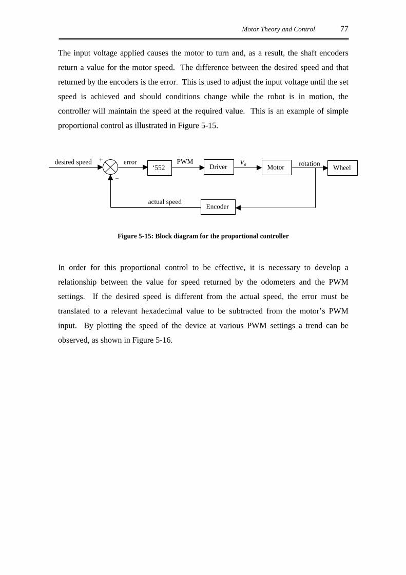
Motor Theory and Control 77
The input voltage applied causes the motor to turn and, as a result, the shaft encoders
return a value for the motor speed. The difference between the desired speed and that
returned by the encoders is the error. This is used to adjust the input voltage until the set
speed is achieved and should conditions change while the robot is in motion, the
controller will maintain the speed at the required value. This is an example of simple
proportional control as illustrated in Figure 5-15.
Figure 5-15: Block diagram for the proportional controller
In order for this proportional control to be effective, it is necessary to develop a
relationship between the value for speed returned by the odometers and the PWM
settings. If the desired speed is different from the actual speed, the error must be
translated to a relevant hexadecimal value to be subtracted from the motor’s PWM
input. By plotting the speed of the device at various PWM settings a trend can be
observed, as shown in Figure 5-16.
Encoderactual speed
MotorDriver Va Wheelrotation desired speed error +
_ ‘552
PWM
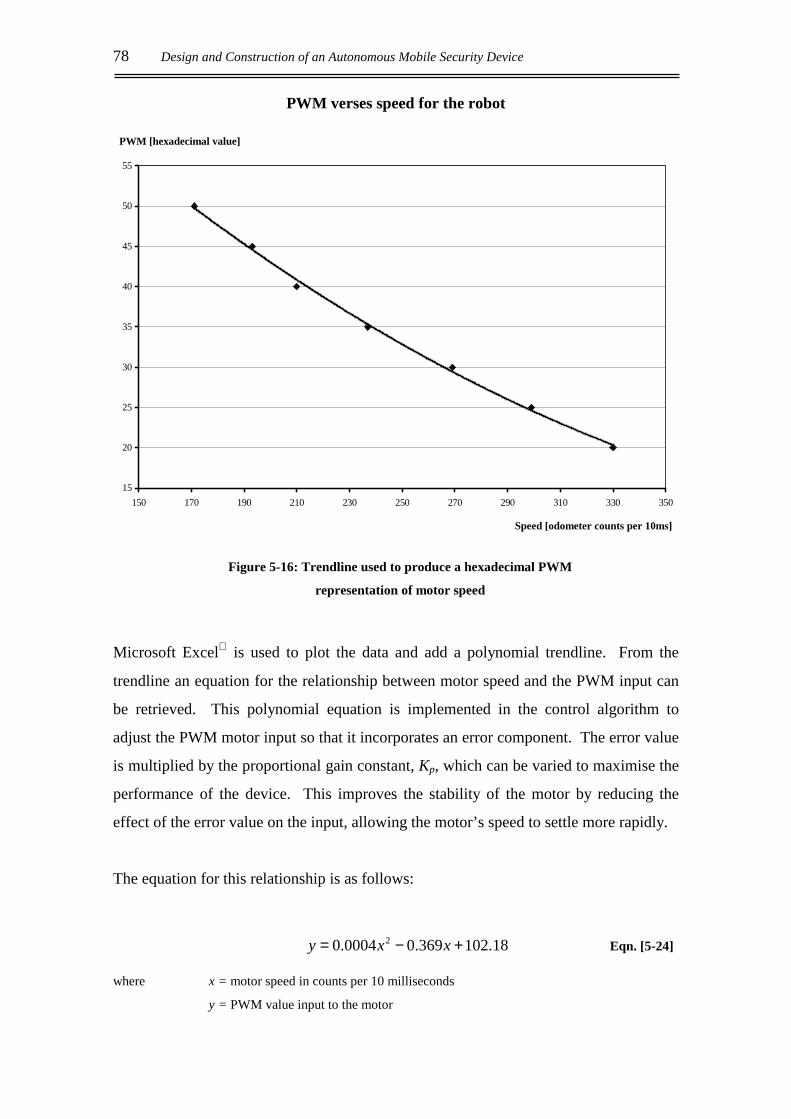
78 Design and Construction of an Autonomous Mobile Security Device
PWM verses speed for the robot
15
20
25
30
35
40
45
50
55
150 170 190 210 230 250 270 290 310 330 350
Figure 5-16: Trendline used to produce a hexadecimal PWM
representation of motor speed
Microsoft Excel is used to plot the data and add a polynomial trendline. From the
trendline an equation for the relationship between motor speed and the PWM input can
be retrieved. This polynomial equation is implemented in the control algorithm to
adjust the PWM motor input so that it incorporates an error component. The error value
is multiplied by the proportional gain constant, Kp, which can be varied to maximise the
performance of the device. This improves the stability of the motor by reducing the
effect of the error value on the input, allowing the motor’s speed to settle more rapidly.
The equation for this relationship is as follows:
18.102369.00004.0 2 +−= xxy Eqn. [5-24]
where x = motor speed in counts per 10 milliseconds
y = PWM value input to the motor
PWM [hexadecimal value]
Speed [odometer counts per 10ms]

Motor Theory and Control 79
Below is a flow diagram for the straight drive function:
Figure 5-17: Flow diagram for straight drive function
The following code segment can be placed in the “while” loop of the straight drive
function in place of lines 7 and 8 of Figure 5-14, to ensure both motors are running at
the correct speed:
speed_lft = 0.0004*(s_lft)^2 – 0.369*s_lft + 102.18;7 speed_rgt = 0.0004*(s_rgt)^2 – 0.369*s_rgt + 102.18;8 lft_motor = speed + (speed - speed_lft)*Kp; //proportional control9 rgt_motor = speed + (speed - speed_rgt)*Kp;10
Figure 5-18: Code segment to implement proportional control
Set desired distance
and speed
Release brakes
Turn on motors at
desired speed
Calculate distance to
stop (x_dec)
Count > xdrive? NO
Shut down the motors
Apply the brakes
YES
Use proportional
control to adjust motor
speed
Wait for robot to stop

80 Design and Construction of an Autonomous Mobile Security Device
Lines 7 and 8 implement the polynomial relationship defined in Equation [5-24], which
converts the speed from the odometers to a PWM value. The proportional control is
executed in lines 9 and 10, where (speed - speed_lft) and (speed - speed_rgt) are the
error values used to implement the closed loop feedback of Figure 5-15.
5.6.3 Turning the Robot
The function developed to turn MARVIN has two inputs, the speed at which to turn and
the angle it is to turn through. This function is similar in many ways to the straight drive
function although some of the characteristic values for the robot’s motion are different
due to the physical nature of the system. The inertia of driving straight from a stationary
beginning is greater than that of the stationary robot executing a turn on the spot. This
variation is illustrated by the difference in the step responses for the turning and straight
drive in Figure 5-19.
Turning and straight drive step responses
0
0.1
0.2
0.3
0.4
0.5
0.6
0.7
0.8
0 0.5 1 1.5 2 2.5 3
Figure 5-19: Turning and straight drive step responses for PWM = 0x50
Speed [m/s]
Turning
Straight drive
Time [sec]
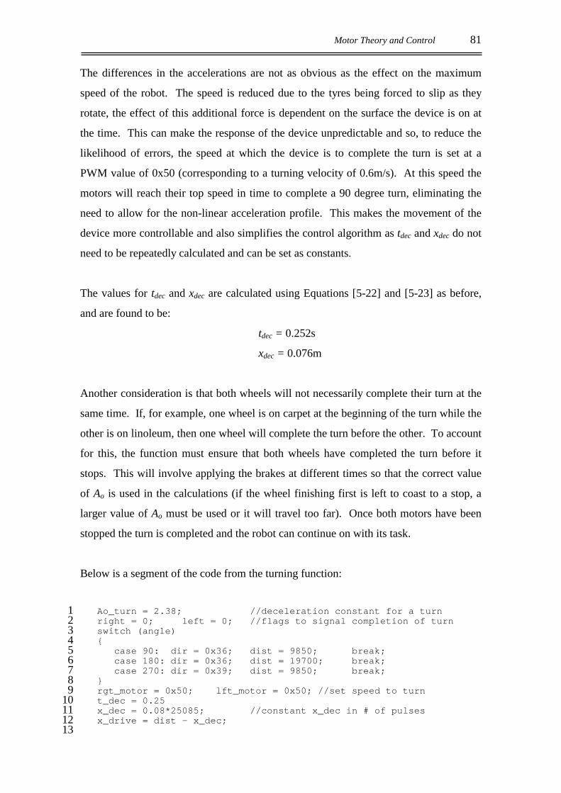
Motor Theory and Control 81
The differences in the accelerations are not as obvious as the effect on the maximum
speed of the robot. The speed is reduced due to the tyres being forced to slip as they
rotate, the effect of this additional force is dependent on the surface the device is on at
the time. This can make the response of the device unpredictable and so, to reduce the
likelihood of errors, the speed at which the device is to complete the turn is set at a
PWM value of 0x50 (corresponding to a turning velocity of 0.6m/s). At this speed the
motors will reach their top speed in time to complete a 90 degree turn, eliminating the
need to allow for the non-linear acceleration profile. This makes the movement of the
device more controllable and also simplifies the control algorithm as tdec and xdec do not
need to be repeatedly calculated and can be set as constants.
The values for tdec and xdec are calculated using Equations [5-22] and [5-23] as before,
and are found to be:
tdec = 0.252s
xdec = 0.076m
Another consideration is that both wheels will not necessarily complete their turn at the
same time. If, for example, one wheel is on carpet at the beginning of the turn while the
other is on linoleum, then one wheel will complete the turn before the other. To account
for this, the function must ensure that both wheels have completed the turn before it
stops. This will involve applying the brakes at different times so that the correct value
of Ao is used in the calculations (if the wheel finishing first is left to coast to a stop, a
larger value of Ao must be used or it will travel too far). Once both motors have been
stopped the turn is completed and the robot can continue on with its task.
Below is a segment of the code from the turning function:
Ao_turn = 2.38; //deceleration constant for a turn1 right = 0; left = 0; //flags to signal completion of turn2 switch (angle)3 4
case 90: dir = 0x36; dist = 9850; break;5 case 180: dir = 0x36; dist = 19700; break;6 case 270: dir = 0x39; dist = 9850; break;7
8 rgt_motor = 0x50; lft_motor = 0x50; //set speed to turn9 t_dec = 0.2510 x_dec = 0.08*25085; //constant x_dec in # of pulses11 x_drive = dist – x_dec;12
13
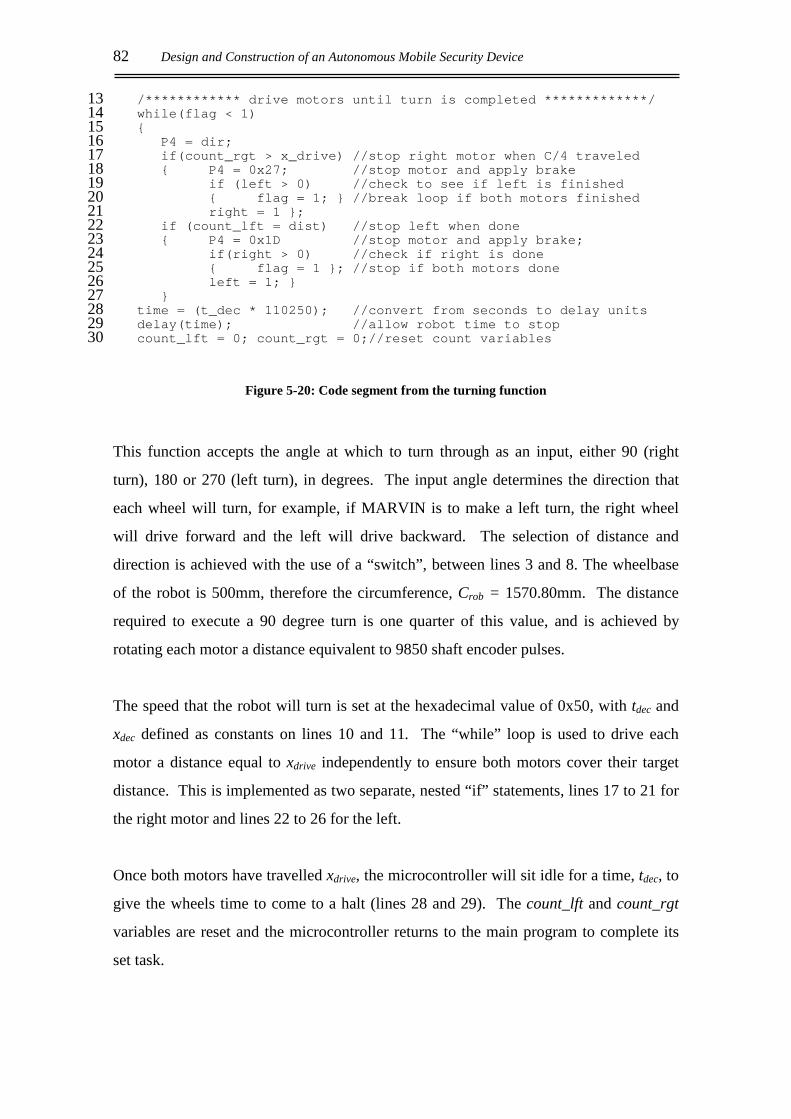
82 Design and Construction of an Autonomous Mobile Security Device
/************ drive motors until turn is completed *************/13 while(flag < 1)14 15
P4 = dir;16 if(count_rgt > x_drive) //stop right motor when C/4 traveled17 P4 = 0x27; //stop motor and apply brake18
if (left > 0) //check to see if left is finished19 flag = 1; //break loop if both motors finished20 right = 1 ;21
if (count_lft = dist) //stop left when done22 P4 = 0x1D //stop motor and apply brake;23
if(right > 0) //check if right is done24 flag = 1 ; //stop if both motors done25 left = 1; 26
27 time = (t_dec * 110250); //convert from seconds to delay units28 delay(time); //allow robot time to stop29 count_lft = 0; count_rgt = 0;//reset count variables30
Figure 5-20: Code segment from the turning function
This function accepts the angle at which to turn through as an input, either 90 (right
turn), 180 or 270 (left turn), in degrees. The input angle determines the direction that
each wheel will turn, for example, if MARVIN is to make a left turn, the right wheel
will drive forward and the left will drive backward. The selection of distance and
direction is achieved with the use of a “switch”, between lines 3 and 8. The wheelbase
of the robot is 500mm, therefore the circumference, Crob = 1570.80mm. The distance
required to execute a 90 degree turn is one quarter of this value, and is achieved by
rotating each motor a distance equivalent to 9850 shaft encoder pulses.
The speed that the robot will turn is set at the hexadecimal value of 0x50, with tdec and
xdec defined as constants on lines 10 and 11. The “while” loop is used to drive each
motor a distance equal to xdrive independently to ensure both motors cover their target
distance. This is implemented as two separate, nested “if” statements, lines 17 to 21 for
the right motor and lines 22 to 26 for the left.
Once both motors have travelled xdrive, the microcontroller will sit idle for a time, tdec, to
give the wheels time to come to a halt (lines 28 and 29). The count_lft and count_rgt
variables are reset and the microcontroller returns to the main program to complete its
set task.
Conclusion 83
6. CONCLUSION
6.1 CAPABILITIES
MARVIN has been designed to operate as an effective mobile security device for
indoor applications. If the robot is to be a suitable platform for such operations, it
must meet the requirements as set out in Section 1.3.
The attributes for the device are divided into the following four categories:
6.1.1 Speed
The average walking pace of a human security guard is 1m/s, as such, this is set as the
speed at which the device is to travel. At this speed the robot will complete its patrol
of the office or warehouse in a reasonable amount of time.
MARVIN’s drive train has been developed from that of an electric wheelchair. The
24V motors supply the driving wheels with sufficient torque to allow MARVIN to
reach speeds in excess of 1.3m/s. In order to obtain more accurate control of the
device, the maximum speed is limited to 1.25m/s, which translates to a PWM value of
0x26. At this speed the braking system can bring the robot to a halt in 0.53 seconds,
over a distance of 0.33m. This is within the range of the IRED proximity sensors and
consequently allows MARVIN to stop in time to avoid collision with a detected
obstacle.
84 Design and Construction of an Autonomous Mobile Security Device
6.1.2 Physical Size
The physical size of the robot is to be suitable for the navigation of an indoor
warehouse or office block environment. The chassis and frame are required to stand
at the height of one metre, to provide future developments with a suitable base from
which to operate. MARVIN stands at a height of 95cm when sitting on the driving
wheels, with the Laser Range Finding assembly, which sits on top of the frame,
adding further height to the device. The chassis and frame have been designed in such
a manner as to permit future expansion, as required.
If the security device is to be the basis for future development, it needs it provide an
adequate base from which future developments can operate. The base chassis of
MARVIN measures 530mm by 560mm with the batteries of the power supply
mounted between the wheels to create a low centre of gravity.
The weight of the device is specified to be at least 30kg to create enough inertia to
negotiate fire doors and stabilise the robot once future developments are added.
MARVIN weighs 49.6kg with the Laser Range Finder and associated electronics.
6.1.3 Manoeuvrability
MARVIN is manoeuvrable enough to navigate within the confines of an office or
corridor, as the differential drive system makes it possible for a turn to be executed
“on the spot”. This system is simple to control due to the less complex mechanics
involved, and the external dimensions of the device allow for a 360 degree turn to be
completed within a circle of diameter equal to 771mm, well within the original
specification of one metre.
The sealed lead-acid batteries of the power supply allow MARVIN to patrol its
operating environment continually without recharging for 110 minutes. This is ample
time for the device to complete a large patrol several times before recharging is
required.
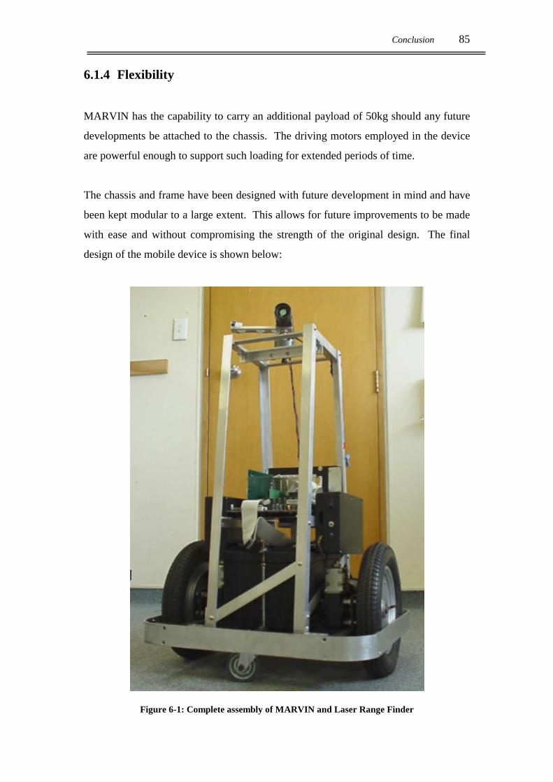
Conclusion 85
6.1.4 Flexibility
MARVIN has the capability to carry an additional payload of 50kg should any future
developments be attached to the chassis. The driving motors employed in the device
are powerful enough to support such loading for extended periods of time.
The chassis and frame have been designed with future development in mind and have
been kept modular to a large extent. This allows for future improvements to be made
with ease and without compromising the strength of the original design. The final
design of the mobile device is shown below:
Figure 6-1: Complete assembly of MARVIN and Laser Range Finder

86 Design and Construction of an Autonomous Mobile Security Device
6.2 FUTURE WORK
MARVIN will be the basis for much research and development at the University of
Waikato in the future. Appendages and improvements will be designed to allow the
robot to operate a lift, open doors and automatically recharge the power supply as
required. Much of this work can be designed and tested independently of the security
device, but MARVIN will provide a basis for the implementation of such
developments.
There is also some additional work to be performed on the security device before the
basic robotic platform is complete:
• As the laser range-finding assembly developed by Shaun Hurd[7] is permanently
attached to the frame of the security device, the Celeron PC motherboard requires
modification in order for it to be powered by the supply from the robot’s batteries.
• At present, the 87C552 Phillips microcontroller and the Celeron motherboard are
totally independent of one another. In the future it is hoped that the PC
motherboard will perform all of the mapping and control calculations due to its
superior processing capability. To implement this the ‘552 must communicate
with the PC either through serial or the more efficient parallel communication
lines.
• Once the security device has the use of the laser range finder for primary obstacle
detection, it will be possible for it to implement a mapping algorithm on its
surroundings. Gary Brightwell[10] has developed the software necessary to
construct a topographical map of a Mobile Autonomous Robot’s environment
with the use of a 360 degree laser range finder. This software can be implemented
to allow MARVIN not only to create an accurate mapping of its immediate
surroundings and identify its position, but also optimise its trajectory.

Conclusion 87
Initially this may be achieved primarily with the range finding assembly or with
the assistance of active or passive beacons. The use of beacons is desirable when
the environment is not very well defined and the immediate environment is subject
to regular change. In such cases it is difficult for a reference point, such as a desk
or wall, to be identified with the required precision to prevent the device from
getting lost.
• The IRED sensors, shaft encoders and laser range finder can be developed so that
each verifies and calibrates the others as necessary. The range finder can be used
to minimise the effects of cumulative odometry errors by correcting any error in
the representation of the distance travelled as calculated by the shaft encoders.
The range finding assembly is only accurate from a distance of approximately
50cm and so the IRED sensors will be required to detect any objects that are closer
to the device.
• The algorithms used by the robot to drive in a straight line for a specified distance
and to execute 90 and 180 degree turns required further development and
refinement to improve the performance of the security device. The functions
written to perform straight drive and turning manoeuvres could be optimised for
speed, as although functional, they could be made more efficient.
As the Laser Range Finder was added late in the development of the device, little
development has been done to incorporate the system into the control of
MARVIN. There is scope for the device to exhibit limited intelligence by using
the knowledge it has of its surroundings. For example, if there is a long straight
ahead of the device, the speed used to travel may be set at a higher value than if it
is required to stop and turn after a short distance. The performance of the device
would also be improved if it could execute an integrated turn while travelling
forward instead of being forced to stop before initiating a turn.
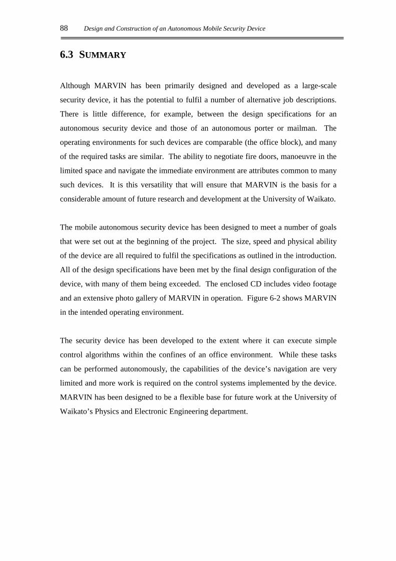
88 Design and Construction of an Autonomous Mobile Security Device
6.3 SUMMARY
Although MARVIN has been primarily designed and developed as a large-scale
security device, it has the potential to fulfil a number of alternative job descriptions.
There is little difference, for example, between the design specifications for an
autonomous security device and those of an autonomous porter or mailman. The
operating environments for such devices are comparable (the office block), and many
of the required tasks are similar. The ability to negotiate fire doors, manoeuvre in the
limited space and navigate the immediate environment are attributes common to many
such devices. It is this versatility that will ensure that MARVIN is the basis for a
considerable amount of future research and development at the University of Waikato.
The mobile autonomous security device has been designed to meet a number of goals
that were set out at the beginning of the project. The size, speed and physical ability
of the device are all required to fulfil the specifications as outlined in the introduction.
All of the design specifications have been met by the final design configuration of the
device, with many of them being exceeded. The enclosed CD includes video footage
and an extensive photo gallery of MARVIN in operation. Figure 6-2 shows MARVIN
in the intended operating environment.
The security device has been developed to the extent where it can execute simple
control algorithms within the confines of an office environment. While these tasks
can be performed autonomously, the capabilities of the device’s navigation are very
limited and more work is required on the control systems implemented by the device.
MARVIN has been designed to be a flexible base for future work at the University of
Waikato’s Physics and Electronic Engineering department.
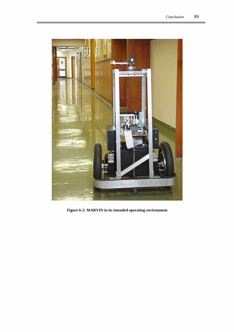
Conclusion 89
Figure 6-2: MARVIN in its intended operating environment

90 Design and Construction of an Autonomous Mobile Security Device

Appendix A 91
APPENDIX A: SCHEMATICS
A.1 87C552 MICROCONTROLLER MOTHERBOARD
VCC
VCC
VCC
VCCVCC
VCC
VCC VCC
VCC
VCC
VCC
VCC
VCC
VCC
VCC
VCC
POWERSUPPLY
RS232CONNECTOR
PROGRAMDATA
DOWNLOAD INDICATOR
D0 D0D1D2D3D4D5
D7D6
D1D2D3D4D5D6D7
D0D1D2D3D4D5D6D7
A0A1A2A3A4A5A6A7A8A9A10A11A12A13A14
A15
A0A1A2A3A4A5A6A7A8A9A10A11A12A13A14
A0A1A2A3A4A5A6A7
P3.0
P3.7 Read
RX
TX
A14
D0
P5.6
D5
P5.3
P3.1
A9A10
A12
D3
A15
NPSEN
ALE
P5.5
A13
D6
D1
A8
A11
P3.6
P3.3
D2
P3.5P3.4
P3.0
NEA
P5.2
P5.7
D7
P3.6 WriteP3.2P3.1
P5.1
D4
P3.7
P3.6P3.5P3.4P3.3P3.2P3.1P3.0
P1.0P1.1P1.2P1.3P1.4P1.5P1.6P1.7
AVDDAVSSAVR+AVR-
STADCNPWM0NPWM1
P5.4
P3.7
P4.0
P5.0
P4.1
P4.7
P4.4
P4.2
P4.5
P4.3
P4.6
P1.0
DATA[0..7]
ADDRESS[0..15]
PORT3[0..7]
U2
74HC573
D13
D24
D35
D02
D46
D57
D68
D79
LE11
OE1
Q0 19
Q118
Q217
Q3 16
Q4 15
Q514
Q613
Q7 12
VCC20
GND 10
U6
232
C1+1
C1-3
C2+4
C2-5
TDI11
RTSI10
RDO12
CTSO9 CTSI 8RDI13
RTSO 7TDO14
V-6
V+ 2
P1
CONNECTOR DB9
594837261
C11
1uF
12
C9
1uF
1 2
C10
1uF
1 2
U5XTAL
12 C6
22pF
C5
22pF
R2
100K
C126u8
S1
RE
SE
T P
US
HB
UTT
ON
JP5
PO
RT
3
123456789
10
JP2
PO
RT
5
123456789
10
JP1
PW
M E
TC
123456789
10 U187C552
160
444327
26
109 61
AD0 57
AD156
AD255
AD3 54
AD4 53
AD552
AD651
AD7 50
ALE48
NEA 49
NPSEN47
A15 46
A1445
A1344
A12 43
A11 42
A1041
A940
A8 39
NPWM15
NPWM04
STADC3
AVR-58
AVR+59
AVSS60
AVDD61
P5.762
P5.663
P5.564
P5.465
P5.366
P5.267
P5.168
P5.01
VCC2
P4.07
P4.18
P4.29
P4.310
P4.411
P4.512
P4.613
P4.714
GND37
GND 36
XTAL135
EXTAL234
P3.0 24
P3.125
P3.226
P3.3 27
P3.428
P3.529
P3.6 30
P3.731
P1.016
P1.117
P1.218
P1.319
P1.420
P1.521
P1.622
P1.723
RS
T15
EW
N6
JP4
PO
RT
1
123456789
10
JP3
PO
RT
4
123456789
10
U77805VIN1 +5 3C
OM
2
D2
1N4001D51N4001 C13
10uFC161uF
C14100nF
C15100nF
R8
330 D3RED
S3ON / OFF
C7
1uF
C4100nF
C3100nF
C2
100nF
R11K
Q2
BS
T70A
R6180
R7180
Q3BST100
R42K2
R32K2
Q1BST70A
D1
1N4001
LED1
TRIC
OLO
R LE
D
A1
1A
22
K3
D4BZX79C15
F1
1A
R5SOT
C1100nF
S2
RUN/DOWNLOAD SWITCH
21
3
54
6
C81uF1
2
DC1DC Connector
+ve1
-ve2
-ve3
J2HEADER 10
12345678910
J1
WATCHDOG
123
BT19V
U3
62256
A010
A19
A28
A37
A46
A55
A64
A73
A825
A924
A1021
A1123
A122
A1326
OE22
CS20
I/O0 11
I/O112
I/O213
I/O3 15
I/O4 16
I/O517
I/O618
I/O7 19
WE27 A14
1
U4
62256
A010
A19
A28
A37
A46
A55
A64
A73
A825
A924
A1021
A1123
A122
A1326
OE22
CS20
I/O0 11
I/O112
I/O213
I/O3 15
I/O4 16
I/O517
I/O618
I/O7 19
WE27 A14
1
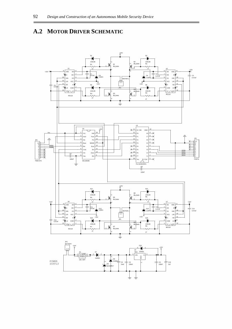
92 Design and Construction of an Autonomous Mobile Security Device
A.2 MOTOR DRIVER SCHEMATIC
+15V
+15V
+15V
+15V
+24V
+15V
+15V
+15V
+15V
+24V
+24V+15V
+15V
POWERSUPPLY
SD1ASD1BSD2ASD2B
PWM1PWM0
Vcc
U1
IR2110
L0 1COM 2
VCC 3
4 4
VS 5
VB 6
HO 788VDD9
HIN10
SD11LIN12
VSS131414
C10.47uF
C40.47uF
R1
27
R3
27
U2
IR2110
L01COM2
VCC3
44
VS5
VB6
HO7 8 8VDD 9
HIN 10
SD 11LIN 12
VSS 1314 14
C20.47uF C3
0.47uF
R2
27
R4
27
JP2
PWM ETC
123456789
10
U6
IR2110
L0 1COM 2
VCC 3
4 4
VS 5
VB 6
HO 788VDD9
HIN10
SD11LIN12
VSS131414
C110.47uF
C140.47uF
R5
27
R7
27
U7
IR2110
L01COM2
VCC3
44
VS5
VB6
HO7 8 8VDD 9
HIN 10
SD 11LIN 12
VSS 1314 14
C120.47uF C13
0.47uF
R6
27
R8
27
D7
1N4001
1 2
D91N4001
12
C510uF
C6100nF
C8100nF
C101uF
D10
1N4001
12
D8BZX55C27
12
JP1
PORT4
12345678910
U4
MC14504B
Vcc1
Aout2
Ain3
Bout4
Bin5
Cout6
Cin7
Vss8 Din 9Dout 10
Ein 11Eout 12
MODE 13Fin 14
Fout 15Vdd 16
U3
PLC18V8Z35FA
I0 / CLK 1I1 2I2 3I3 4I4 5I5 6I6 7I7 8I8 9
GND 10I9 / !OE11
F012
F113
F214
F315
F416
F517
F618
F719
Vcc20
C9
100nF
C7
100nF
JP4
MOTOR 2
12
JP5
MOTOR 1
12
JP3BATTERY
1 2
Q4IRLZ44N
1
23
Q2IRLZ44N
1
23
Q1IRLZ44N1
23
Q3IRLZ44N1
23
Q5IRLZ44N1
23
Q7IRLZ44N1
23
Q8IRLZ44N
1
23
Q6IRLZ44N
1
23
S1
ON / OFF
12
43
D311DF4
D1
1N4148
D5
1N4148
D411DF4
D2
1N4148
D6
1N4148
D1311DF4
D11
1N4148
D15
1N4148
D1411DF4
D12
1N4148
D16
1N4148
U57815
VIN1 +5 3CO
M2
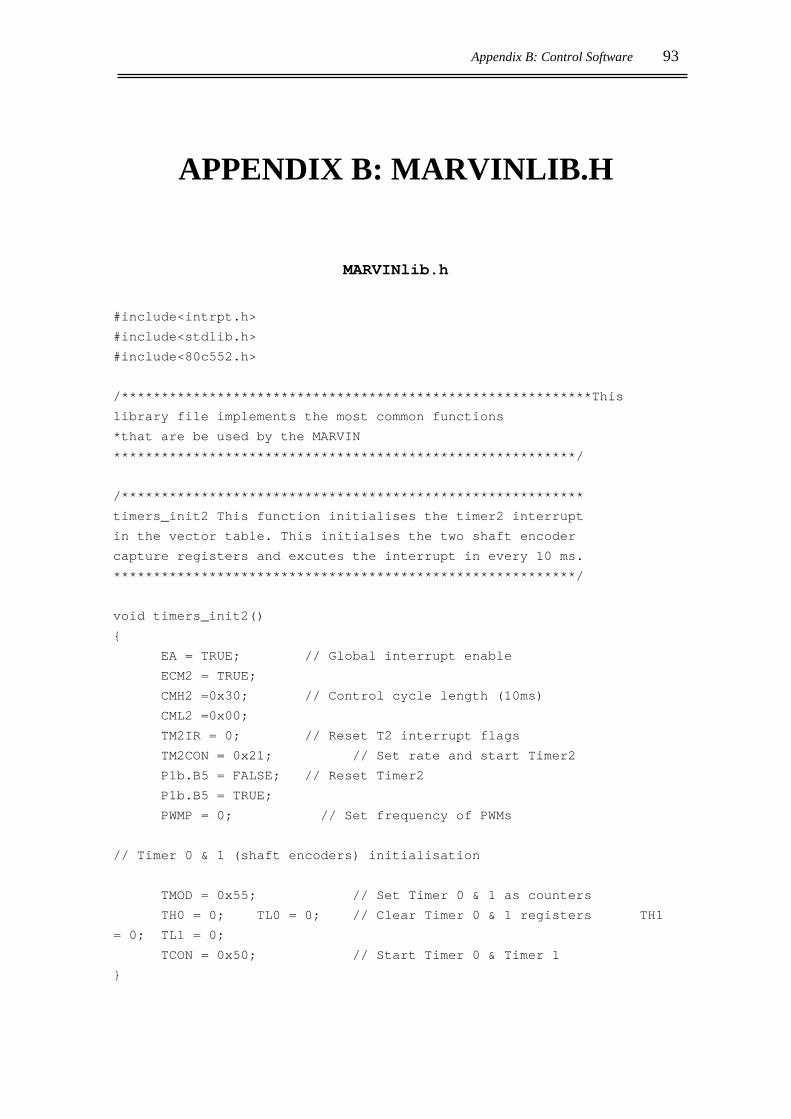
Appendix B: Control Software 93
APPENDIX B: MARVINLIB.H
MARVINlib.h
#include<intrpt.h>
#include<stdlib.h>
#include<80c552.h>
/***********************************************************This
library file implements the most common functions
*that are be used by the MARVIN
**********************************************************/
/**********************************************************
timers_init2 This function initialises the timer2 interrupt
in the vector table. This initialses the two shaft encoder
capture registers and excutes the interrupt in every 10 ms.
**********************************************************/
void timers_init2()
EA = TRUE; // Global interrupt enable
ECM2 = TRUE;
CMH2 =0x30; // Control cycle length (10ms)
CML2 =0x00;
TM2IR = 0; // Reset T2 interrupt flags
TM2CON = 0x21; // Set rate and start Timer2
P1b.B5 = FALSE; // Reset Timer2
P1b.B5 = TRUE;
PWMP = 0; // Set frequency of PWMs
// Timer 0 & 1 (shaft encoders) initialisation
TMOD = 0x55; // Set Timer 0 & 1 as counters
TH0 = 0; TL0 = 0; // Clear Timer 0 & 1 registers TH1
= 0; TL1 = 0;
TCON = 0x50; // Start Timer 0 & Timer 1
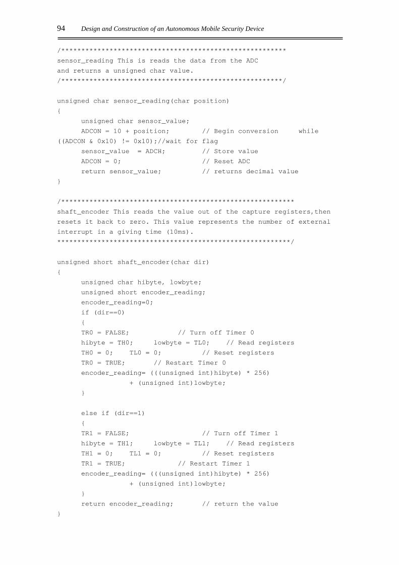
94 Design and Construction of an Autonomous Mobile Security Device
/********************************************************
sensor_reading This is reads the data from the ADC
and returns a unsigned char value.
/*******************************************************/
unsigned char sensor_reading(char position)
unsigned char sensor_value;
ADCON = 10 + position; // Begin conversion while
((ADCON & 0x10) != 0x10);//wait for flag
sensor_value = ADCH; // Store value
ADCON = 0; // Reset ADC
return sensor_value; // returns decimal value
/**********************************************************
shaft_encoder This reads the value out of the capture registers,then
resets it back to zero. This value represents the number of external
interrupt in a giving time (10ms).
**********************************************************/
unsigned short shaft_encoder(char dir)
unsigned char hibyte, lowbyte;
unsigned short encoder_reading;
encoder_reading=0;
if (dir==0)
TR0 = FALSE; // Turn off Timer 0
hibyte = TH0; lowbyte = TL0; // Read registers
TH0 = 0; TL0 = 0; // Reset registers
TR0 = TRUE; // Restart Timer 0
encoder_reading= (((unsigned int)hibyte) * 256)
+ (unsigned int)lowbyte;
else if (dir==1)
TR1 = FALSE; // Turn off Timer 1
hibyte = TH1; lowbyte = TL1; // Read registers
TH1 = 0; TL1 = 0; // Reset registers
TR1 = TRUE; // Restart Timer 1
encoder_reading= (((unsigned int)hibyte) * 256)
+ (unsigned int)lowbyte;
return encoder_reading; // return the value

Appendix B: Control Software 95
/*********************************************************
delay This wastes the processor's time
**********************************************************/
void delay(unsigned long int time)
unsigned short index;
for (index=0; index< time;index++);
/**********************************************************serial_init
Used for uploading of data to the PC. configures the serial I/O port
of the '552 to transmit at a baud rate of 9600 using timer1,
transmitting in the format: bit (0) first, followed by 8 data bits
(Lsb first), followed by the stop bit(1);
**********************************************************/
void serial_init()
EA=FALSE; // disable interrupts
TM2CON=0; // stop timer T2
TCON=0; // stop timer 0
PCON=0x80; // double baud rate
TMOD=0x20; // configure timer 1 to count
TH1= 0; //initailise register TH1
TH1 = 248; TL1=0; //set baud rate
TR1=TRUE; // start timer 1
S0CON=0x40; // 8 bit UART serial I/O
REN = TRUE; // enable reception
/**********************************************************output_asc
Used in uploading ascii data to the PC. Writes
the byte value to the serial port buffer and waits for confirmation of
transmission.
**********************************************************/
void output_asc(unsigned short byte)
S0BUF=byte;
while ((S0CON & 0x02) !=0x02);
TI = FALSE;

96 Design and Construction of an Autonomous Mobile Security Device
/**********************************************************
output_dec Used in uploading decimal data to the PC. Writes
the byte value to the serial port buffer and waits for
confirmation of transmission.
**********************************************************/
void output_dec(unsigned long this)
unsigned char a,b,c,d,e,f;
a=(this/100000)+48; this%=100000;
b=(this/10000)+48; this%=10000;
c=(this/1000)+48; this%=1000;
d=(this/100)+48; this%=100;
e=(this/10)+48;
f=(this%10)+48;
S0BUF=a;
while((S0CON&0x02) != 0x02); TI =FALSE;
S0BUF=b;
while((S0CON&0x02) != 0x02); TI =FALSE;
S0BUF=c;
while((S0CON&0x02) != 0x02); TI =FALSE;
S0BUF=d;
while((S0CON&0x02) != 0x02); TI =FALSE;
S0BUF=e;
while((S0CON&0x02) != 0x02); TI =FALSE;
S0BUF=f;
while((S0CON&0x02) != 0x02); TI =FALSE;
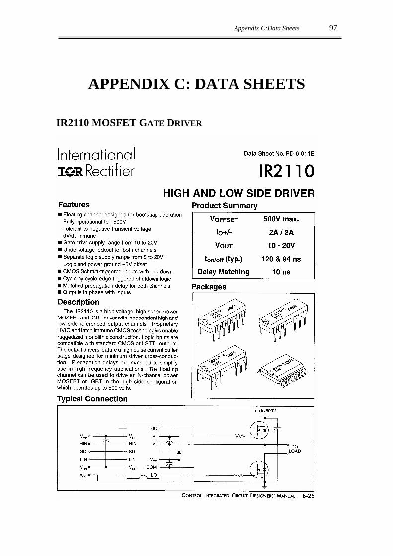
Appendix C:Data Sheets 97
APPENDIX C: DATA SHEETS
IR2110 MOSFET GATE DRIVER

98 Design and Construction of an Autonomous Mobile Security Device
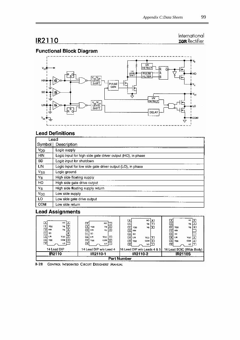
Appendix C:Data Sheets 99

100 Design and Construction of an Autonomous Mobile Security Device

Appendix C:Data Sheets 101
IRLZ44N POWER MOSFET

102 Design and Construction of an Autonomous Mobile Security Device
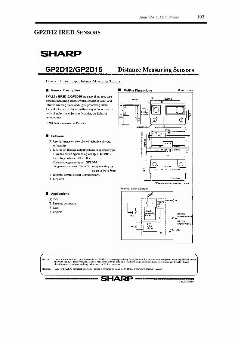
Appendix C:Data Sheets 103
GP2D12 IRED SENSORS
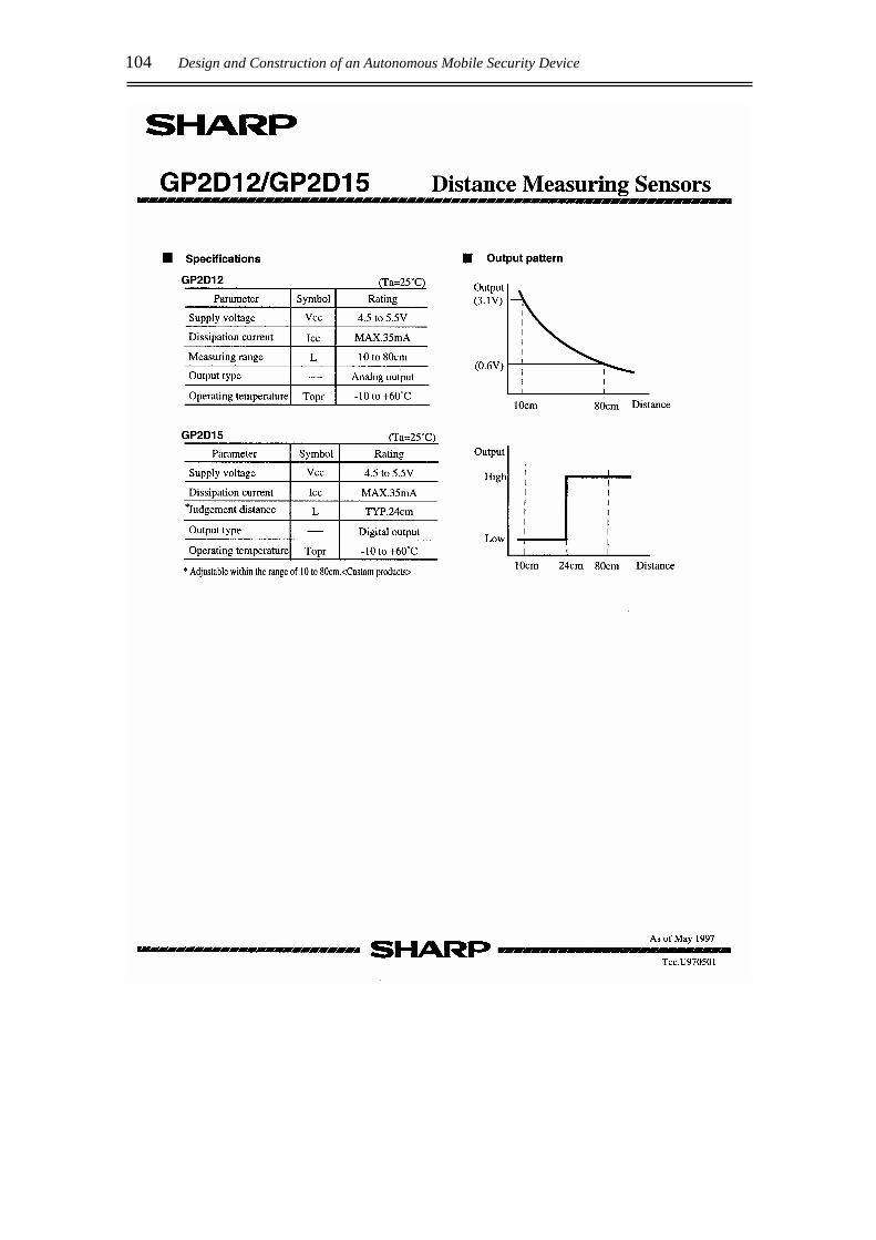
104 Design and Construction of an Autonomous Mobile Security Device
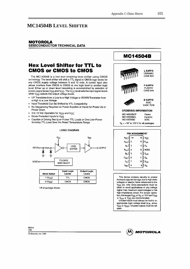
Appendix C:Data Sheets 105
MC14504B LEVEL SHIFTER
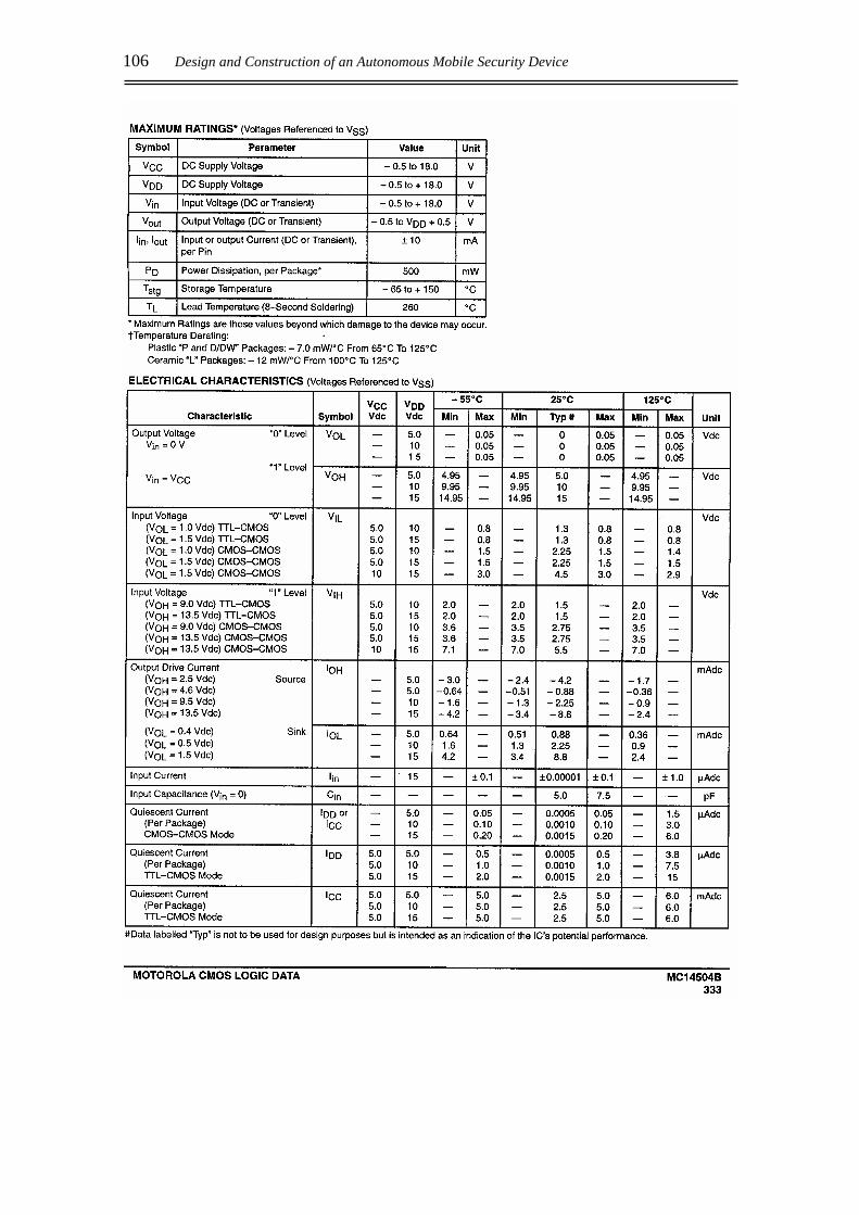
106 Design and Construction of an Autonomous Mobile Security Device
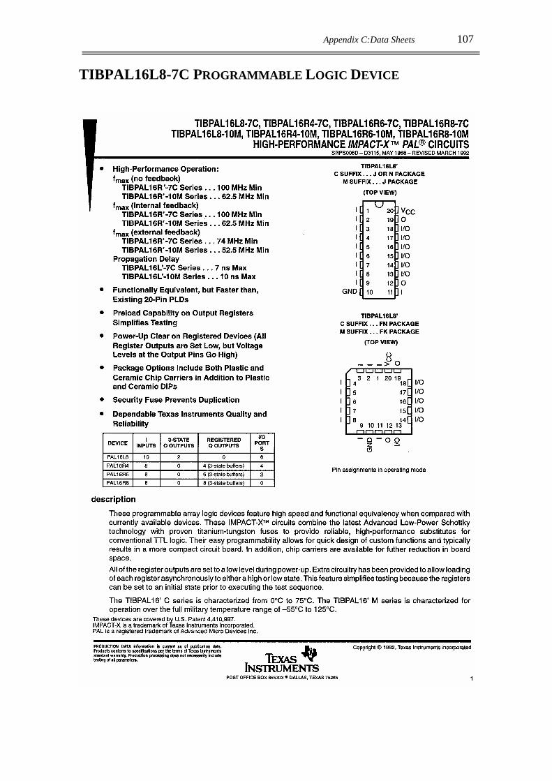
Appendix C:Data Sheets 107
TIBPAL16L8-7C PROGRAMMABLE LOGIC DEVICE
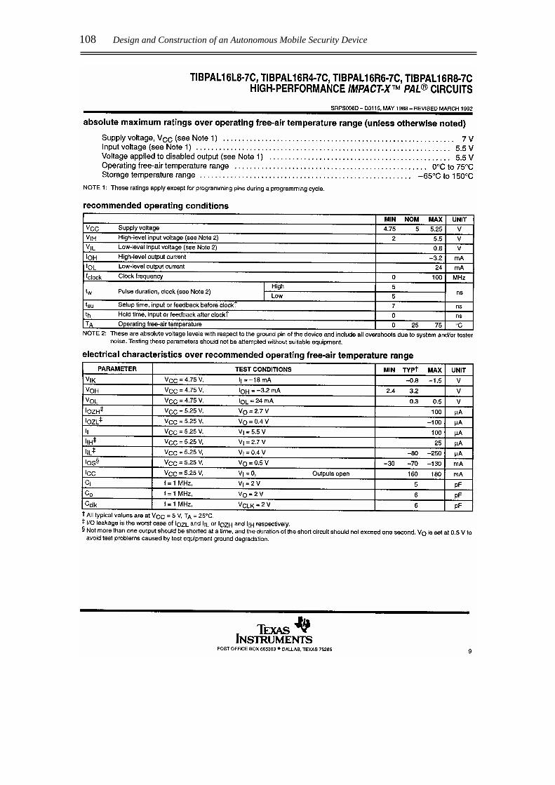
108 Design and Construction of an Autonomous Mobile Security Device

Glossary 109
GLOSSARY
‘552 Phillips 87C552 microprocessor
ADC Analogue to Digital Converter
AGV Automated Guided Vehicle
Bit Binary Digit – either 0 or 1
Byte 8 bits
CCA Cold Cranking Amps – a measure of a battery’s capacity [A]
CCD Charge-Coupled Device
DAC Digital to Analogue Converter
DC Direct Current
DPDT Double Pole / Double Throw switch
Emf Electro-magnetic field
EPROM Electronically Programmable Read Only Memory
FLA Flooded Lead Acid battery
GPS Global Positioning System – an advanced active beacon system
I2C Phillips serial communication protocol
I/O Input/Output
IC Integrated Circuit
LSB Least Significant Bit
MARVIN Mobile Autonomous Robot for Indoor Navigation
MDARS Mobile Detection Assessment and Response System
MOSFET Metal Oxide Semiconductor Field Effect Transistor
MSB Most Significant Bit of a binary value
NiCd Nickel Cadmium – material used to manufacture rechargeable batteries
PSD Position Sensitive Device
PWM Pulse width modulation – a square wave of constant duty cycle is used as
an approximation to a DC voltage
RAM Random Access Memory

110 Design and Construction of an Autonomous Mobile Security Device
RC Reserve Capacity - a measure of a battery’s capacity [min]
R/F Radio Frequency - a form of wireless communication
ROBART I The world’s first autonomous security robot
SLA Sealed Lead Acid battery
TOF Time Of Flight
TTL Transistor to Transistor Logic
UART Universal Asynchronous Receiver/Transmitter
UMBmark University of Michigan Benchmark experiments
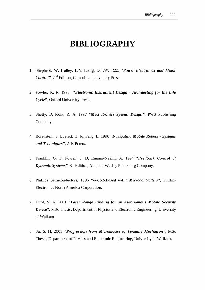
Bibliography 111
BIBLIOGRAPHY
1. Shepherd, W, Hulley, L.N, Liang, D.T.W, 1995 “Power Electronics and Motor
Control”, 2nd Edition, Cambridge University Press.
2. Fowler, K. R, 1996 “Electronic Instrument Design - Architecting for the Life
Cycle”, Oxford University Press.
3. Shetty, D, Kolk, R. A, 1997 “Mechatronics System Design”, PWS Publishing
Company.
4. Borenstein, J, Everett, H. R, Feng, L, 1996 “Navigating Mobile Robots - Systems
and Techniques”, A K Peters.
5. Franklin, G. F, Powell, J. D, Emami-Naeini, A, 1994 “Feedback Control of
Dynamic Systems”, 3rd Edition, Addison-Wesley Publishing Company.
6. Phillips Semiconductors, 1996 “80C51-Based 8-Bit Microcontrollers”, Phillips
Electronics North America Corporation.
7. Hurd, S. A, 2001 “Laser Range Finding for an Autonomous Mobile Security
Device”, MSc Thesis, Department of Physics and Electronic Engineering, University
of Waikato.
8. Su, S. H, 2001 “Progression from Micromouse to Versatile Mechatron”, MSc
Thesis, Department of Physics and Electronic Engineering, University of Waikato.

112 Design and Construction of an Autonomous Mobile Security Device
9. Borenstein, J. and Feng, L, 1996, “Measurement and Correction of Systematic
Odometry Errors in Mobile Robots”, IEEE Transactions on Robotics and
Automation, Vol. 12, No. 6.
10. Brightwell, G, 1999 “Analysis of Adaptive Reactive Control Systems for
Autonomous Mobile Robots”, DPhil Thesis, Department of Physics and Electronic
Engineering, University of Waikato.
11. Brightwell, G, 1993, “Design and Construction of a Micromouse”, MSc Thesis,
Department of Physics and Electronic Engineering, University of Waikato.
12. Taberner, A. J, 1994, “Design and Construction of a Microcat”, MSc Thesis,
Department of Physics and Electronic Engineering, University of Waikato.
13. Everett, H. R, 1995 “Sensors for Mobile Robots: Theory and Application”, A. K
Peters, Ltd.
14. Exide Batteries, http://www.exide.co.nz
15. Farnell Online, http://www.farnell.com
16. SPAWAR Systems Centre, San Diego, http://www.spawar.navy.mil
17. Chip Centre International, http://www.chipcenter.com/
18. IC Masters Online, http://xilinx.icmaster.com
19. International Rectifier, http://www.irf.com
20. Power Designers, Electrical Engineering and Design Solutions,
http://www.powerdesigners.com/


![Spectrum Analysis using Cisco Spectrum Expert, Autonomous ... · Eile. Spectrum Active Devices 802.15.4 Devices [2] Device 1 14802.15.44[1] Device 1 Bluetooth [2] Piconet 3 [2] Device](https://img.pdfslide.net/doc/110x75/5f94b02b87bb3c64783d0f2a/spectrum-analysis-using-cisco-spectrum-expert-autonomous-eile-spectrum-active.jpg)