Embed Size (px)
Citation preview
2015 Earth structures and retention conference
Design and construction of rock fall protection embankments
James CrocarisGeotechnicsArup
24th November 2015

Contents
1. context and background information2. need for RPS at Port Hills, Christchurch and property zoning3. alternative rockfall protection structures overview4. rockfall protection embankments and design procedure5. key design considerations and lessons learnt 6. case studies7. conclusions
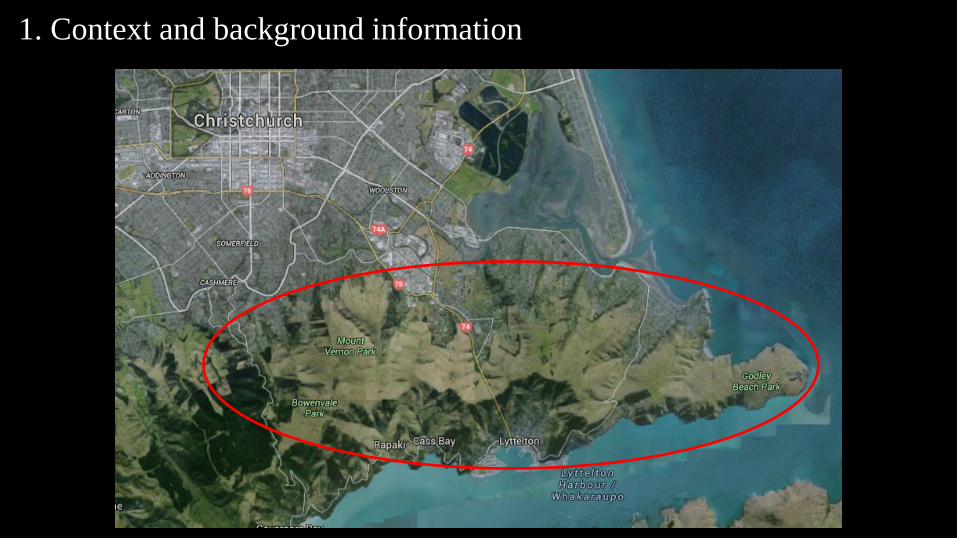
1. Context and background information

Earthquake damage
GNS
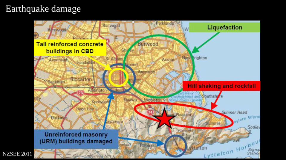
Earthquake damage
NZSEE 2011

2. Property Zoning
Following the Canterbury earthquake of 2011, properties were categorised as ‘red zoned’ or ‘green zoned’.
Canterbury Earthquake Recovery Authority (CERA) defines properties that are ‘red zoned’ as “Properties affected by rock roll have been zoned red where they face an unacceptable risk to life (greater than 1 in 10,000 at 2016 risk levels), A total of 714 properties were classified as within the ‘red zone’
GNS 2012

3. Alternative rockfall protection structures
Prevention of rockfall (primary measure)
• Benefits
• reduces likelihood of rockfall occurring and/or reduces the boulder size at the rockfall source
• Methods
• rock anchors, rock breaking, installation of mesh
• Limitations
• costly, high risk construction and maintenance, heavily dependent on identification of rock masses likely to dislodge
Source: www.can.ltd.uk
Source: www.gabionsupplier.com

3. Alternative rockfall protection structures
Barriers or attenuation fences (secondary measure)
• Benefits
• typically installed with small footprint
• Methods
• Chain link fence
• Limitations
• upon impact, chain link can deform several meters,
• not considered appropriate where rockfall energy >1500kJ, and
• requires regular maintenance following rockfall events.
Source: www.can.ltd.uk
Source: www.gabionsupplier.com
Source: www.slopemesh.com
Source: www.hitechrockfall.com

4. Rock fall protection embankments
• secondary mitigation measures
• Benefits
• can resist high kinetic energy rock fall events,
• embankments have been constructed to resist up to +10,000kJ of energy,
• geometry and fill materials can vary
• Methods
• embankment facing can vary
• rockfall ditch
• Limitations
• installation footprint
• Potential to act as a dam
Source: Maccaferri
Source: Lambert, 2013

https://www.youtube.com/watch?v=TMGwVrXmh-o

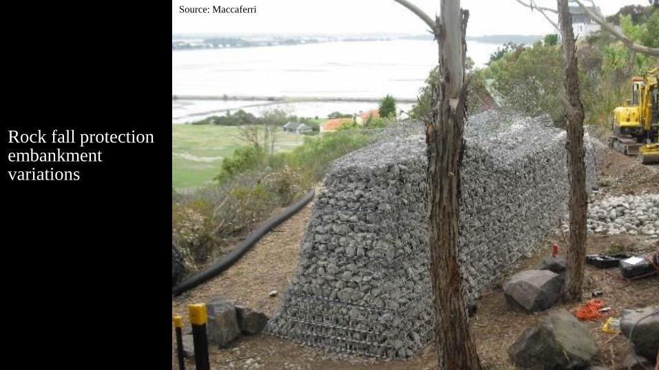
Rock fall protection embankment variations
Source: Maccaferri
Rock fall protection embankment variations
Source: Maccaferri

Rock fall protection embankment variations
Source: Lambert
2013

Rock fall protection embankment variations
Source: Lambert
2013

Rock fall protection embankment variations
Source: Lambert
2013

Rock fall protection embankment variations

Rock fall embankment design approaches
Multiple design approaches exist for the design of rock fall protection embankments, which vary in complexity:
• Mass balance,• Factor of Safety,• Pseudo-static,• Energy balance, or• Numerical modelling
Arup’s adopted method for projects in the Port Hills was an energy balance approach
Source: Brunet 2009Source: Murashev 2013

Rock fall embankment design approach adopted
Multiple variables prevent standardised design procedure in Australia/NZ for rockfall protection embankments, including:• geometry, • fill material, • construction methods,• reinforcement option (geogrid, steel mesh, spacing), and• dynamic behaviour of soil.
This design approach is outlined in detail in Ronco, 2009
Modifications were made to meet the requirements of the Christchurch City Council (CCC) technical guidelines for rock fall protection
Design procedure involves two stages:1. Assessment of rockfall energy levels, and2. Design of the rock fall protection embankment.
Source: Brunet 2009

Assessment of rockfall energy levels
Rockfall analysis at specific sites found:
• energy levels often in excess of 6000kJ,
• boulder size in the order of 1.2m3, and
• velocity in excess of 25m/s.

Assessment of rockfall energy levels
Rockfall analysis at specific sites found:
• energy levels often in excess of 6000kJ,
• boulder size in the order of 1.2m3, and
• velocity in excess of 25m/s.

Assessment of rockfall energy levels
Rockfall analysis at specific sites found:
• energy levels often in excess of 6000kJ,
• boulder size in the order of 1.2m3, and
• velocity in excess of 25m/s.

Assessment of rockfall energy levels
Rockfall analysis at specific sites found:
• energy levels often in excess of 6000kJ,
• boulder size in the order of 1.2m3, and
• velocity in excess of 25m/s.

Assessment of rockfall energy levels
Rockfall analysis at specific sites found:
• energy levels often in excess of 6000kJ,
• boulder size in the order of 1.2m3, and
• velocity in excess of 25m/s.

Physical and topographic survey findings are input into rockfall simulationOutputs
• anticipated trajectory,
• nominal design energy (DEL) energy levels,
• bounce height, and
• Velocity.
Used to decide the type and location of RPS
DEL parameters obtained from rockfall analysis are factored based on ETAG 27 requirements
Rockfall modelling is a strong tool in deciding on the location of the embankment
Source: Maccaferri
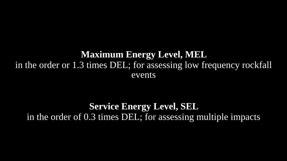
Maximum Energy Level, MEL in the order or 1.3 times DEL; for assessing low frequency rockfall
events
Service Energy Level, SEL in the order of 0.3 times DEL; for assessing multiple impacts

Geometry and Deformation
Up Slope deformation
• The penetration due to plasticisation/ compression,
• Maximum sliding of the soil layers
Down slope deformation
• only the ‘maximum sliding of soil layers’
The geometry of the RPE is determined by multiple elements, including:
1. Impact bounce height;
2. Tolerable deformation from boulder impact and construction requirements;
3. Global slope stability;
4. Global embankment stability due to accelerations from earthquakes; and
5. Effects of the embankment acting as a dam should also be considered.
Source: Ronco 2009

https://www.youtube.com/watch?v=TMGwVrXmh-o

Global Stability

Natural terrain Depth/thickness
Access Tracks
Drainage
Geometry of embankment
Embankment fill

6. Case study A
MEL in the order of 7000kJ
Embankment was considered most suitable mitigation measure
Visual surveys carried out by Arup
Embankment position options were considered with contractor and client
Design allowed balance of cut to fill, minimising construction cost
Excavated rock was proposed to fill embankment
Down slope maximum height 7.5m
Retaining wall utilised up slope
Commercial product proposed

6. Case study B

Conclusions
• Effective, sustainable rebuild strategy,• Low cost, low maintenance,• Site and construction constraints should be considered
early in design• No guidelines for the design of embankments exist in Australia, however large
amounts of literature and international guidance exists,

Thank you
James CrocarisGeotechnicsArup
24th November 2015