Embed Size (px)
Citation preview


Emory University – Campus Services Design and Construction Standards Table of Contents
*Underlined text indicates changes from prior year. Page 1 of 4
Design and Construction Standards
February, 2016
TABLE OF CONTENTS
2016 Design Standards Review Comments Summary
Warranty Matrix- Summary of warranty requirements throughout Design and Construction Standards
FM Global Matrix – Summary of FM Global coordination requirements organized by Section.
Division 00 — Procurement and Contracting Requirements 00 00 02 Introduction 00 00 03 Space Needs 00 63 00 Clarifications and Proposals
Division 01 – Internal Requirements 01 11 00 Summary of Work Requirements 01 31 00 Project Management and Coordination 01 32 00 BIM Guidelines – Scope, Deliverables & Progress 01 33 23 Submittals, Shop Drawings, Product Data 01 41 00 Standard Of Quality and Regulatory Requirements 01 43 39 Mock Ups 01 50 00 Temporary Facilities and Contractor Mobilization 01 74 00 Cleaning 01 75 00 Starting and Adjusting 01 77 00 Close-Out Procedures 01 78 23 Operation and Maintenance 01 79 00 Demonstrations and Training 01 81 13 Sustainable Design Requirements 01 91 13 General Commissioning Requirements 01 91 19 Facility Shell Commissioning 01 94 00 Facility Decommissioning
Division 02 – Existing Conditions 02 62 00 Hazardous Waste Recovery Processes
FACILITY CONSTRUCTION
Division 03 – Concrete 03 00 00 Concrete
Division 04 – Masonry 04 00 00 Masonry
Division 05 – Metals 05 00 00 Metals
Division 06 – Wood, Plastic, and Composites 06 00 00 Wood, Plastic, and Composites
Division 07 – Thermal and Moisture Protection 07 20 00 Thermal Protection
Renamed

Emory University – Campus Services Design and Construction Standards Table of Contents
*Underlined text indicates changes from prior year. Page 2 of 4
Division 07 – Thermal and Moisture Protection (continued) 07 30 00 Steep Slope Roofing 07 50 00 Built-Up Bituminous Roofing 07 60 00 Flashing and Sheet Metal 07 84 00 Firestopping
Division 08 – Openings
08 00 00 Openings & Doors (includes Wood and Laminate Doors) 08 50 00 Windows 08 70 00 Hardware 08 80 00 Glass and Glazing
Division 09 – Finishes
09 20 00 Plaster and Gypsum Board 09 30 00 Tile 09 51 00 Acoustical Lay-In Ceilings 09 65 00 Resilient Flooring 09 68 00 Carpet 09 90 00 Paints and Coatings 09 95 00 Wall Coverings
Division 10 – Specialties
10 10 00 Graphics and Signage 10 21 13 Toilet Compartments 10 28 13 Toilet Accessories 10 43 00 Defibrillator, AED Cabinet and Sign 10 44 00 Fire Protection Specialties
Division 11 – Equipment Requirements 11 24 29 Facility Fall Protection 11 53 13 Fume Hoods 11 53 53 Biological Safety Cabinets
Division 14 – Conveying Equipment 14 20 00 Elevators
FACILITY SERVICES
Division 21 – Fire Suppression 21 13 00 Fire-Suppression Sprinkler Systems 21 30 00 Fire Pump
Division 22 – Plumbing
22 00 00 Plumbing Division 23 – Heating, Ventilating, and Air-Conditioning (HVAC)
23 00 00 Mechanical Narrative and Information 23 05 00 Basic Materials & Methods 23 05 14 Variable Frequency Motor Controls 23 05 19 Utility Metering 23 05 93 Testing, Adjusting, and Balancing for HVAC 23 07 00 HVAC Insulation 23 08 00 Commissioning of HVAC 23 09 00 Instrumentation and Control for HVAC 23 21 23 Hydronic Pumps 23 22 00 Steam & Condensate Specialties 23 25 00 HVAC Water Treatment
New Section

Emory University – Campus Services Design and Construction Standards Table of Contents
*Underlined text indicates changes from prior year. Page 3 of 4
Division 23 – Heating, Ventilating, and Air-Conditioning (HVAC) continued 23 25 00a New Building Chemical Station Turn Over 23 25 00b Cooling Tower Control Board 23 30 00 HVAC Air Distribution 23 50 00 Central Heating Equipment 23 57 00 Heat Exchangers for HVAC 23 60 00 Central Cooling Equipment 23 63 13 Refrigerant Condensers 23 64 16 Centrifugal Water Chillers 23 65 13 Cooling Towers 23 65 23 Field-Erected Cooling Towers 23 70 00 HVAC Equipment
Division 26 – Electrical Electrical Systems Narrative 26 00 00 Electrical General Requirements 26 01 00 Basic Electrical Systems Testing By Electrical Contactor 26 05 00 Basic Electrical Materials and Methods 26 08 00 Commissioning of Electrical Systems 26 10 00 Medium-Voltage Electrical Distribution 26 20 00 Electrical Service & Distribution 26 29 00 Variable Speed Drives 26 30 00 Standby Power Generator Systems 26 50 00 Lighting 26 60 00 Special Electrical Systems (see Division 28)
Division 27 – Communications
27 00 00 Emory University Library & Information Technology Services Standards Division 28 – Electronic Safety and Security
28 10 00 Electronic Security Systems 28 31 00 Fire Detection and Alarm
SITE AND INFRASTRUCTURE
Division 31 – Earthwork 31 00 00 Earthwork 31 10 00 Tree Protection and Selective Clearing 31 25 00 Construction Storm Water and Erosion Control
Division 32 – Exterior Improvements
32 00 00 Exterior Improvements 32 12 00 Flexible Paving 32 12 16 Asphalt Paving 32 12 43 Porous Flexible Paving 32 13 13 Concrete Paving 32 16 13 Concrete Curbs and Gutters 32 17 13 Car Stops 32 17 23 Pavement Markings 32 80 00 Irrigation 32 90 00 Planting 32 92 00 Turf and Grasses

Emory University – Campus Services Design and Construction Standards Table of Contents
*Underlined text indicates changes from prior year. Page 4 of 4
Division 33 – Utilities
33 10 00 Water Utilities 33 30 00 Sanitary Sewerage Utilities 33 40 00 Storm Drainage Utilities 33 60 00 Steam and Chilled Water Distribution Systems
Additional Documents by Reference:
All referenced document can be downloaded from Campus Services Design and Construction Standard website: http://www.campserv.emory.edu/pdc/planning_construction/Design_Standards_with_Guidelines.html
Building Information Modeling (BIM)
BIM Execution Plan (BEP) template
BIM Asset Information Database (BIM-AID) template Substantial Completion / Closeout Document Requirements:
Document Delivery Standards
Architectural Floor Plan Template.dwg
Evacuation Template.dwg
Design Guidelines: 2012 Campus Design Guidelines
Campus Master Plan Guidelines
Emory College Classroom Design Guide

Division / Section Comment/Issue/Section Response & Action Taken
Emory University Design & Construction Standards – 2016 Comments & Revisions Page 1 of 1
Other Document Delivery Standards 2014 AutoCAD Map 3D 2014 is now required.
Division 01 – Internal Requirements
00 00 03 Space Needs Electrical Room and Mechanical Room size specified.
00 00 03 Space Needs Move space narratives / “Building Considerations” from MEP sections: 23 00 00 and 26 00 00.
00 00 03 Space Needs Storm Shelter information added.
01 33 23 Submittals, Shop Drawings, and Product Data
New Section: Equipment Submittal / Shop Drawing Review Process.
01 81 13 Sustainable Design Requirements Multiple paragraphs deleted. Read section thoroughly.
Division 08 – Openings 08 80 00 Windows Added Window Film requirements.
Division 10 – Specialties 10 43 00 Defibrillator, AED Cabinet and Sign New Section. Read section thoroughly.
Division 14 – Conveying Systems 14 20 00 Elevators Removed recall requirement from pit sprinkler activation, updated manufacturer list, added
temperature and humidity control information, modified warranty and inspection information, coaxial cable requirement added, and updates to Owner Information prior to final acceptance.
Division 22 – Plumbing 22 00 00 Plumbing Testing instruction added.
Division 23 – Heating, Ventilating, And Air-Conditioning (HVAC) 23 00 00 Mechanical Systems Narrative General revisions throughout and multiple paragraphs deleted. Read section thoroughly.
23 30 00 HVAC Air Distribution Direct injection steam humidification information added. Duct sealant VOC requirements modified.
23 60 00 Central Cooling Equipment Removed Central B Chiller Plant reference.
23 70 00 HVAC Equipment Updated Emory’s energy calculation data, deleted Variable Speed Drives information, updated air Handling Units section.
Division 26 – Electrical Division 26 Electrical Systems Narrative Paragraph 4- Building Distribution condensed. Energy modeling requirement added.
23 05 00 Basic Materials & Methods Class 125WA, 150, 150F Requirements modified. Motor specification modified.
26 20 00 Electrical Service & Distribution Secondary Power Distribution within Buildings: replace fluorescents with LED.
26 30 00 Standby Power Generator Systems Generator manufactures modified, and egress lighting requirements for non-generator emergency power.
26 50 00 Lighting Building Automated System overrides and LED Pole Fixture requirements added.
26 05 00 Basic Electrical Materials and Methods Arc-Flash Stickers shall be located on all panels, An Electrical riser diagram left in a secure location main electrical room of each building.
Division 33 – Utilities 33 40 00 Storm Drainage Utilities Added Oxford College Stormwater Management Plan.
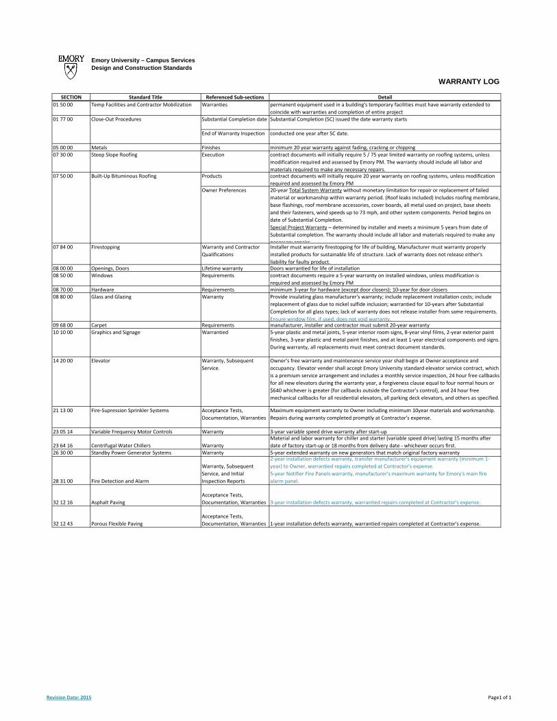
WARRANTY LOG
SECTION Standard Title Referenced Sub‐sections Detail
01 50 00 Temp Facilities and Contractor Mobilization Warranties permanent equipment used in a building's temporary facilities must have warranty extended to
coincide with warranties and completion of entire project01 77 00 Close‐Out Procedures Substantial Completion date Substantial Completion (SC) issued the date warranty starts
End of Warranty Inspection conducted one year after SC date.
05 00 00 Metals Finishes minimum 20 year warranty against fading, cracking or chipping07 30 00 Steep Slope Roofing Execution contract documents will initially require 5 / 75 year limited warranty on roofing systems, unless
modification required and assessed by Emory PM. The warranty should include all labor and
materials required to make any necessary repairs.07 50 00 Built‐Up Bituminous Roofing Products contract documents will initially require 20 year warranty on roofing systems, unless modification
required and assessed by Emory PMOwner Preferences 20‐year Total System Warranty without monetary limitation for repair or replacement of failed
material or workmanship within warranty period. (Roof leaks included) Includes roofing membrane,
base flashings, roof membrane accessories, cover boards, all metal used on project, base sheets
and their fasteners, wind speeds up to 73 mph, and other system components. Period begins on
date of Substantial Completion.
Special Project Warranty – determined by installer and meets a minimum 5 years from date of
Substantial completion. The warranty should include all labor and materials required to make any
necessary repairs07 84 00 Firestopping Warranty and Contractor
Qualifications
Installer must warranty firestopping for life of building, Manufacturer must warranty properly
installed products for sustainable life of structure. Lack of warranty does not release either's
liability for faulty product. 08 00 00 Openings, Doors Lifetime warranty Doors warrantied for life of installation08 50 00 Windows Requirements contract documents require a 5‐year warranty on installed windows, unless modification is
required and assessed by Emory PM08 70 00 Hardware Requirements minimum 3‐year for hardware (except door closers); 10‐year for door closers08 80 00 Glass and Glazing Warranty Provide insulating glass manufacturer's warranty; include replacement installation costs; include
replacement of glass due to nickel sulfide inclusion; warrantied for 10‐years after Substantial
Completion for all glass types; lack of warranty does not release installer from same requirements.
Ensure window film, if used, does not void warranty.09 68 00 Carpet Requirements manufacturer, installer and contractor must submit 20‐year warranty10 10 00 Graphics and Signage Warrantied 5‐year plastic and metal joints, 5‐year interior room signs, 8‐year vinyl films, 2‐year exterior paint
finishes, 3‐year plastic and metal paint finishes, and at least 1‐year electrical components and signs.
During warranty, all replacements must meet contract document standards.
14 20 00 Elevator Warranty, Subsequent
Service.
Owner’s free warranty and maintenance service year shall begin at Owner acceptance and
occupancy. Elevator vender shall accept Emory University standard elevator service contract, which
is a premium service arrangement and includes a monthly service inspection, 24 hour free callbacks
for all new elevators during the warranty year, a forgiveness clause equal to four normal hours or
$640 whichever is greater (for callbacks outside the Contractor’s control), and 24 hour free
mechanical callbacks for all residential elevators, all parking deck elevators, and others as specified.
21 13 00 Fire‐Supression Sprinkler Systems Acceptance Tests,
Documentation, Warranties
Maximum equipment warranty to Owner including minimum 10year materials and workmanship.
Repairs during warranty completed promptly at Contractor's expense.
23 05 14 Variable Frequency Motor Controls Warranty 3‐year variable speed drive warranty after start‐up
23 64 16 Centrifugal Water Chillers Warranty
Material and labor warranty for chiller and starter (variable speed drive) lasting 15 months after
date of factory start‐up or 18 months from delivery date ‐ whichever occurs first. 26 30 00 Standby Power Generator Systems Warranty 5‐year extended warranty on new generators that match original factory warranty
28 31 00 Fire Detection and Alarm
Warranty, Subsequent
Service, and Initial
Inspection Reports
2‐year installation defects warranty, transfer manufacturer's equipment warranty (minimum 1‐
year) to Owner, warrantied repairs completed at Contractor's expense.
5‐year Notifier Fire Panels warranty, manufacturer's maximum warranty for Emory's main fire
alarm panel.
32 12 16 Asphalt Paving
Acceptance Tests,
Documentation, Warranties 3‐year installation defects warranty, warrantied repairs completed at Contractor's expense.
32 12 43 Porous Flexible Paving
Acceptance Tests,
Documentation, Warranties 1‐year installation defects warranty, warrantied repairs completed at Contractor's expense.
Emory University – Campus ServicesDesign and Construction Standards
Revision Date: 2015 Page1 of 1

FM GLOBAL LOGSECTION Standard Title Referenced Sub‐sections Detail
00 00 02 Introduction Owner Property Insurance
All design and installation must incorporate loss prevention guidelines as dfined by FM Global Data Sheet
standards and should utilize FM Global‐approved equipment or systems whenever available.
All design plans must be submitted to FM Global’s Atlanta office for review where final acceptance will
be subject to the local FM Global engineering office.
A consultant responsible for spec and/or install of a non‐FM Global‐approved item is liable for all costs
involved in correcting the deviation to the approval of FM Global.
01 31 00 Project Management + Coordination CommissioningEmory PM will notify FM Global of time and date for pump acceptances, alarm system acceptance
testing, special protections (FM200, etc.) acceptance tests and combustion control acceptance testing.
Pre‐Construction ConferenceFM Global will also be invited to the pre‐construction conference as well as other conferences and
meetings as deemed necessary by the project.
01 33 23 Submittals, Shop Drawings, Product Data FM Global
FM Global provides loss prevention consulting and should be involved in the review of all plans.
Additional drawings that must be submitted to FM Global for review, if not included with General
Construction drawings, are: Fire protection materials and fire pump layout and equipment specs, roof
cover system, integrated exterior finishing systems, pre‐engineered all‐metal building systems, gas fired
heating equipment, special protection systems, and fire protection monitoring and general fire alarm
systems.
01 91 19 Facility Shell Commissioning Design Phase Responsibilities The Ecx shall review design for compliance with FM Global requirements.
05 00 00 Metals Quality Assurance
Steel decking utilized for roof construction should be FM Global approved and limited to the span widths
under which it is approved. Structural steel components of the building must comply with the
requirements of FM Global.
07 20 00 Thermal Protection Quality Assurance All insulation products and/or systems are to be FM Global approved.
ProductsPolyisocyanurate insulation is FM Global’s preferred product to be used under clay tile and low slope
roofs.
07 30 00 Steep Slope Roofing Quality Assurance
The design of all roof cover systems should be in designed in accordance with FM global standards
utilizing a FM approved assembly that is rated for the associated wind hazards with appropriate
reinforcement at the perimeter edges and corners, or written approval must be obtained from the
Emory’s Project Manager to be in non‐compliance with FM Global recommendations. The FM Global
Contractor's Application for Roof Acceptance form must be submitted with each roof submittal.
07 50 00 Built‐Up Bituminous Roofing Quality Assurance
The design of all roof cover systems should be in designed in accordance with FM global standards
utilizing a FM approved assembly that is rated for the associated wind hazards with appropriate
reinforcement at the perimeter edges and corners, or written approval must be obtained from the Emory
Project Manager to be in non‐compliance with FM Global recommendations. The FM Global Contractor's
Application for Roof Acceptance form must be submitted with each roof submittal.
Owner Preferences: COLD Applied AssembliesThe roof system installed should be FM Global approved as listed in the most recent edition of the FM
Global Approval Guide.
Execution
The contract documents must include requirements for inspection and review of the substrates under
the roofing system(s) and complete details showing installation of the roofing system in compliance with
all requirements of FM Global, UL, governing authorities and codes and the manufacturer.
07 60 00 Flashing and Sheet Metal Quality Assurance
The design of all flashed assemblies and systems and manufacturer's products must be approved by FM
Global, reference data sheet 1‐49 which covers guidelines for flashing installation, or have the written
approval of Emory’s Project Manager.
08 80 00 Glazing Quality Assurance
The selection of glass and the design of glazing systems shall comply with FM Global requirements, code
requirements and wind load requirements for the project site as well as ASHRAE recommended
standards to comply with the current LEED requirements.
21 13 00
21 30 00
Fire‐Suppression Sprinkler Systems
Fire PumpsRegulatory Requirements
All fire protection design and installation should be in accordance with FM Global Standards. All drawings
should be submitted to the Emory University Project Manager and FM Global for approval. Field
installations are subject to FM Global acceptance in addition to approval of the AHJ. Work performed
shall comply with FM Global Approval Guide and FM Data Sheets. Drawings and specifications to be
reviewed can be sent to the attention of Plan Review Engineers (for Emory University) ,), FM Global,
3460 Preston Ridge Drive, Alpharetta, GA 30005.
21 13 00 Fire‐Suppression Sprinkler Systems Design and Sprinkler Occupancy Guidelines
For the occupancies that are typical to Emory buildings, there is little difference in the sprinkler densities
required by FM Global and Codes.
Laboratories: FM Global requires 0.15 gpm/sq. ft. over 2500 sq. ft.
Mech/Small Storage Rooms: FM Global requires 0.15 gpm/sq. ft. over 2500 sq. ft.
Exhibit Halls with unusually high ceilings: FM Global requires 0.30 gpm/sq. ft. over 5000 sq. ft.
For other occupancies, the FM Global plan review department should be contacted at (770) 777‐3084 for
guidance.
21 30 00 Fire Pumps Fire Pumps
Fire pumps shall be located inside a two hour minimum rated room. Rated mechanical rooms are
acceptable. Higher rating of room shall be determined by FM Global and/or the Fire Marshall.
TB Woods or any plastic fire pump couplings are prohibited by FM Global for the fire pump.
28 31 00 Fire Detection and Alarm References
Plans are subject to FM Global review and installation is subject to FM Global acceptance. In the event
that it is subsequently discovered that the work, or any portion of the work, has not used the necessary
approved materials, equipment, or services, or has otherwise not been performed in accordance with FM
Global standards, or for any reason does not meet with FM Global acceptance, the Contractor
responsible for the work shall, at its own expense and without any cost to Emory University, within forty‐
five (45) days of notice in writing of any deficiency (or within such times as the parties to this contract
have agreed in writing), perform such work and replace such materials as is necessary to bring the work
and materials into compliance with relevant FM Global standards and secure FM Global acceptance.

SECTION Standard Title Referenced Sub‐sections Detail
28 31 00 Fire Detection and Alarm (continued) SubmittalsOne (1) copy shall be sent to: FM Global, 3460 Preston Ridge Road, Suite 400, Alpharetta GA 30005
Regulatory RequirementsEquipment and materials shall be approved for their designed use and performance. The term
"approved" shall mean Underwriters Laboratories (UL) listed and FM Global approved.

Emory University – Campus Services Section 00 00 02 Design and Construction Standards Introduction
Revision Date – December, 2015 Section Page 1 of 3
Section 00 00 02 – Introduction Purpose The purpose of these Design and Construction Standards is to provide specific guidelines to architects, engineers, design consultants, and contractors for all construction activities on Emory University properties. These Standards are intended to summarize information that is unique to Emory University either by choice, by the specialized nature of the facility, or by the requirements of the university’s insurance carrier and to avoid historical problems with construction, operations, and maintenance. It is recognized that these Design and Construction Standards are not universally applicable to every project. These standards do not replace professional design analyses and may not be used directly as contract specifications. Consultants shall conduct independent evaluations, discuss alternatives and recommendations with the Emory Project Manager, and appropriate Campus Services personnel. The Emory Project Manager must approve all deviations from these Standards in writing. All references to Project Manager shall mean Emory Project Manager. Designers and contractors are to become familiar with and are responsible for all sections of the Standards, and are to incorporate the appropriate information early in the design and construction process. In so doing, designers should be able to save time in preparing plans and specifications, as well as shorten the review time by Emory University personnel. Additional themes running throughout these Standards is Emory University's building commissioning program, and support of the University’s sustainability vision which are an integral part of the Standards. CSI 2004 Format Emory University has converted the Design and Construction Standards to the CSI 2004 Format in support of Campus Service’s continuing role as an industry leader, to proactively meet standards of practice, and for its improved documentation capabilities. While Emory has chosen to provide information to its consultants in this format there is no obligation for the consultant to use this format at this time. It is understood that the industry is in a mode of transition. Additional information on the new format can be found at www.csinet.org/masterformat. 2015 Design Update Summary Attached to these standards is a document titled 2015 Design Standards Review Comments Summary. This matrix highlight the substantive changes contained within this version of the Design and Construction Standards. Do not depend on this table to include every change but it should assist with finding many of the modifications from the previous year. Comprehensive BIM Management Plan Emory University is committed to achieving excellence in every aspect of design and construction. It is our continued efforts for excellence that has led us to add Building Information Modeling (BIM) to our design, construction and facilities program through our Comprehensive BIM Management Plan, developed to achieve the highest levels of quality, value and efficiency in our capital programs and increase the level of service at more efficient cost levels in facilities management and operations. The BIM process begins with programming and planning, and extends through design and construction, through turnover, and into facilities management and operations. BIM encompasses all aspects of a building’s life cycle, including major capital improvements and repairs, energy efficiency, LEED, remodeling, adaptive reuse and life safety.

Emory University – Campus Services Section 00 00 02 Design and Construction Standards Introduction
Revision Date – December, 2015 Section Page 2 of 3
Your participation in the Comprehensive BIM Management Plan helps build an organized, consistent BIM database for the design, construction and management of facilities at Emory University. Agreements Emory University currently uses Emory generated and proprietary contracts for design, engineering, and construction services. A proprietary short-form contract is also available; however, the use of this contract is extremely limited. These contracts have been edited to meet Emory's specific policies and needs. Any additional modification of these documents will require review and acceptance by Emory's General Counsel. The Emory Project Manager will determine which contracts will be used for the project and will prepare all contracts that Emory University is a party to. The Design and Construction Standards must be considered as part of a total contract that may include other attachments and guidelines depending on the project. These attachments may impact information presented in these standards and must be evaluated by the consultant with the Emory Project Manager. Possible attachments include… • Program Document • Facilities Condition
Assessment • Feasibility Study • DAR Guidelines • College Classroom
Guidelines
• Campus Design Guidelines • Sustainability Guidelines • Accessible Design Service • LITS Standards • Supplemental Conditions
• Document Delivery Standards
• BIM Asset Information Database Spreadsheet
• BIM Execution Plan (BEP) template
Notice of Commencement Unless Owner direct otherwise, Contractor shall record a Notice of Commencement, on the form provided in the contract documents with the Clerk of the Superior Court of the County where the Project is located within fifteen (15) days of physically commencing Work at the Site. Hazardous Materials It is the policy of Emory University, that prior to any restoration, alteration, demolition or renovation of any area the Environmental Health and Safety Office (EHSO) assess the area for environmental hazards. The Emory Project Manager manages this effort. Examples of environmental hazards are items such as, but not limited to, presence of: asbestos-containing materials and/or lead-based paint, biological, chemical including PPCB ballast and florescent light bulbs, and radiation hazards. The presence of biological, radiation and chemical hazards will be found primarily in the laboratory/research environment. Presence of asbestos-containing materials and lead-based paint coated surfaces can be found in and on all types of building materials as well as laboratory-related equipment. For specific requirements pertaining to the noted hazards, refer to the project manager. Owner Property Insurance - FM Global All design and installations should incorporate loss prevention guidelines as defined by FM Global Data Sheet standards and should utilize FM Global approved equipment or systems when available. All design plans should be submitted to FM Global's Atlanta office for review, and final acceptance subject to the local FM Global engineering office. The consultant responsible for specifying and/or installing an item not approved by FM Global will be liable for all costs involved in correcting the deviation to the approval of FM Global. This liability includes, but is not limited to, the cost of re-design, removal and re-installation, project management and Emory University costs incurred, relocation and accommodation of any users involved, and any possible additional insurance or risk management coverage that would be required due to the deviation.
Emory University – Campus Services Section 00 00 02 Design and Construction Standards Introduction
Revision Date – December, 2015 Section Page 3 of 3
Outages and Hot Work Hot Work is defined as work requiring concrete cutting, brazing, grinding, welding or soldering of metals, or work producing gases or particulate capable of activating ionization or smoke/heat detectors. Failure to notify Owner of this work that results in Fire Department false alarm will result in pass-through of false alarm fine to Contractor. See Section 01 31 00 for preconstruction requirements. Sustainability All projects are to be USGBC LEED Certified at the Silver level as a minimum unless noted otherwise in the contracts for professional design services or construction services. The Emory Project Manager will provide additional information on related project consultants and processes. “Space Needs” (previously Basic Program Requirements) as well as most sections in the Design and Construction Standards address sustainability objectives and lessons learned. Campus Services Organization Emory University's Campus Services manages the planning, design construction, physical operation and maintenance of Emory's campuses and the included facilities. Construction projects can fit into this management system in several different ways. Your Emory Project Manager will be your single point of contact as the project moves forward. The typical project will have a Planning representative as the Project Manager through Design Development and might switch to a Construction Project Manager representative from construction documents through construction and the completion of the warranty period. Updated organizational charts and project status reports can be found at the Campus Services web site. http://campserv.emory.edu/
Emory University – Campus Services Section 00 00 03 Design and Construction Standards Space Needs
Revision Date – December, 2015 Section Page 1 of 3
Section 00 00 03 – Space Needs Scope Throughout the Design and Construction Standards there are requirements for various dedicated spaces or rooms typically with minimum areas, required fixtures furnishings and equipment, and utilities. These spaces must be considered in the development of any project with any deviation agreed to in writing with the Emory Project Manager. The design team shall identify the proximity of existing Changing Rooms, Bicycle Storage Rooms, Lactation Rooms and Single Occupant/Family Restrooms in nearby Emory buildings and determine the need for each of these types of spaces for each building project. The determination of need for each of these types of spaces shall be conducted in collaboration with the Project Manager and the University Architect. The Project Manager and University Architect must approve the decision as to whether these spaces should be included in new building projects. Building Services, Custodial and Building Maintenance Space requirements for Building Services/Maintenance Rooms, Custodial Staff Support Rooms, Custodial Support Rooms, Janitorial Rooms, Residence Hall Custodial Supervisor Office, Attic Stock Storage and Loading Docks can be found under section 01 78 23. Electrical Services On most Emory University buildings (all but very small buildings) we want to see electrical rooms with panelboards at both ends of the building or in the building center. In some cases with two electrical rooms on a floor a smaller closet may be allowed at one end if approved by Engineering Services. Electrical rooms must be stacked to utilize vertical chase arrangements, etc. It is unacceptable to feed an entire floor from only one end of a large building. All corridors that are adjacent to these electrical rooms (sources of power) must have accessible lay in ceilings. It is unacceptable to place an electrical room behind a lobby area which contains a hard or inaccessible ceiling unless spare conduits with a number and size as determined in consultation with Emory’s Electrical Engineer are installed to bridge this space. Electrical rooms should be at least 6 feet wide by 8 feet long. Mechanical Services Doors to mechanical rooms larger than 200 square feet shall have an opening of 6 feet. For buildings 100,000 square feet or larger, penthouse mechanical rooms shall be served by an elevator. Mechanical room elevator access requirements shall be discussed with Emory Facilities Management and Engineering Services prior to completion of the building layout design. The elevator cab is to be large enough to facilitate the removal of the largest part of the equipment in the mechanical room. For penthouse mechanical rooms that are not served by an elevator, a monorail and trolley are to be provided to facilitate the removal of equipment through a floor hatch or opening. Sustainability In accordance with Emory’s LEED requirements, every project will need to incorporate the following spaces:
1. Bicycle Storage and Changing Rooms: Every project must consider covered bicycle storage and the need for a single occupant, ADA compliant shower, and changing room within a 200 feet radius. This room is intended to provide building occupants with a viable alternative transportation option. Additionally, if it is feasible within the building program, ‘extra’ showers may be added to be available for future projects. This potential should be reviewed with the Project Manager during Schematic Design. Following this guidance will also enable the project to achieve Sustainable Sites Credit 4.2 - Alternative Transportation - Bicycle Storage & Changing Rooms under the current LEED rating system.
2. Recycling Rooms: Recycling room requirements can be found under section 01 78 23.

Emory University – Campus Services Section 00 00 03 Design and Construction Standards Space Needs
Revision Date – December, 2015 Section Page 2 of 3
Universal Design In accordance with Emory’s universal design and workplace quality objectives every project will need to consider the need for the following spaces:
1. Lactation Rooms: Every project, except for residential projects, must consider the need for a single occupant ADA compliant lactation room to support Emory General Policy 4.91 - Lactation Support Program. The room will provide privacy for the mother while pumping or feeding and must include or have access to a hand-washing sink. Typically these rooms are best located off or near a women’s restroom. Room with privacy lock will have suitable furnishings (chair, side table, bulletin board, magazine/literature holder, and waste basket) and electrical outlets for pump and small under-counter lockable refrigerator. Room should also have a small wash sink, shelving or countertop for disinfectant spray, soap/paper towel dispenser. Also provide in use/ vacant sign.
2. Single Occupant/Family Restroom: Every project, except for residential projects, must consider one single occupant unisex ADA compliant restroom adjacent to and visible from the public areas of the building that can also be used as a child changing room.
Storm Shelter Area The design team should follow the recommendations of the following publications to identify a safe shelter area for emergency events such as tornadoes. Selecting Refuge Areas in Buildings FEMA P-431, Second Edition/October 2009 Design and Construction Guidance for Community Safe Rooms FEMA 361, 2nd Edition The following considerations should be addressed in the building design: Selection Criteria
• Determine how much space is needed to house building occupants • Standing or seated: 5 SF per person • Wheelchair: 10 SF • Bedridden children or adults: 30 SF • Review construction drawings and inspect buildings to identify strongest portion(s) of the building • Assess site for potential pole, tree, or tower fall down and windborne missiles
Protective Elements
• Lowest floor • Below ground space is almost always the safest • Interior partitions, secured to roof and floor, without windows • Short roof spans • Rigid frames • Poured in place, reinforced concrete, reinforced masonry, or connected steel frames
Hazardous Elements
• Long span roofs • Light weight roofs • Heavier roofs • Windows • Unprotected corridors • Loadbearing walls • Masonry construction without vertical reinforcement

Emory University – Campus Services Section 00 63 00 Design and Construction Standards Clarifications and Proposals
Revision Date – August, 2010 Section Page 1 of 1
Section 00 63 00 - Clarifications and Proposals General It is understood that the purpose of Change Orders is to modify the contract and that Requests for Information, Interpretation, or Clarifications are to explain project conditions without generating a proposal or change to the contract. Clarifications Clarifications are responses to Request for Information or Interpretation (RFI's). All clarifications must be in writing. If a clarification will impact the contract, the contractor shall follow the contract modification procedures per the contract. Clarifications shall be traced on the Contractor generated RFI Log. Field Directives / Field Orders Field Directives / Field Orders shall be used in only urgent situations. A field Directive must be tracked on the Construction Change Directives Log and must be closed by an issued Change Order, Architects Supplemental Instructions or a RFI/clarification item as soon as is possible. Proposed Changes All change proposals shall be requested and responded to in writing. Each change proposal shall include a description of construction schedule impacts and a date when the information in the proposal expires. All change proposals accepted by Emory University will be converted to or incorporated in a Change Order in a timely fashion. Change proposals and proposal requests shall be tracked on the Contractor generated Item of Change Log.
Emory University – Campus Services Section 01 11 00 Design and Construction Standards Summary of Work Requirements
Revision Date – May, 2013 Section Page 1 of 1
Section 01 11 00 - Summary of Work Requirements General This section of the project manual is to be dedicated to a detailed narrative of the summary of the work. This narrative must include a description of the scope of the work for each designer and consultant as well as the Owner and the Owner's consultants and contractors. The design intent and parameters of each building system must be defined with the definitions using as much quantitative information as possible. Documentation of Owner and user knowledge and understanding of the design intent and the completed facility's performance expectations must be explained. Facility programming reports and the translation of these reports into design parameters shall also be included in this specification section. This section of the specification shall be organized in such a fashion that all expectations of the performance of the building can be easily obtained and referenced during the commissioning and occupation of the facility. Generic descriptions, references to industry or local standards, or weakly defined design intent are not acceptable for this section or for contract performance at Emory University. Specific Requirements Project Title - Each project will be given an official title and Building ID for use during the duration of the project. The project title shall appear on all documents related to the Project. Emory may, at any time, revise the project title and require all documents to be revised accordingly. Legal Description - Legal descriptions shall appear in every complete set of drawings. The background for the legal description can be obtained from the archives of Campus Services CSIT. Street Addresses - Street addresses for projects are assigned by the DeKalb County development review authorities. Describe the conditions for partial occupancy, if any will be permitted or required. Identify the extent of the Owner's on-site operations, if the Owner intends to continue these during construction. Appropriate topics for Summary of Work include:
1. Work covered by Contract Documents 2. Contracts 3. Work under other contracts 4. Future work 5. Work sequence 6. Contractor use of premises 7. Occupancy requirements: Owner occupancy; Partial occupancy; Continued occupancy; and,
Maintenance of operation 8. Products ordered in advance 9. Owner furnished products 10. BIM Execution Plan
Building Information Modeling (BIM) Guidelines & Standards The Building Information Modeling (BIM) program is implemented at Emory University to achieve excellence in the design, construction and management of facilities at Emory. The BIM Execution Plan (BEP), prepared by the AE and the CM/GC, is the core of the work plan for programming, designing, evaluating, constructing and operating our facilities. The BIM modeling process and the database that is developed through the BEP, fosters open and shared collaboration among the AE, the CM/GC and Campus Services and coordinated, consistent and accurate information to be used by all over the useful life of the building.

Emory University – Campus Services Section 01 31 00 Design and Construction Standards Project Management and Coordination
Revision Date – November, 2014 Section Page 1 of 4
Section 01 31 00 – Project Management and Coordination Summary The Architect is responsible for complete and thorough coordination and detail of the Contract Documents. The Architect is also responsible for accurate documentation of any existing conditions pertaining to the project. The Contractor is responsible for overall coordination of the construction of the project. Cooperation among the various crafts and contracts will be necessary for the proper execution of the Work. Prior to the installation and connection of mechanical and electrical work of Divisions 23 and 26 to the work of other divisions; the work of the Owner; or the work of other contracts:
1. Verify the requirements indicated in Division 23 and 26, with the requirements and characteristics of the other crafts, Owner or other contractor's equipment.
2. Before installation, make provisions to avoid interference with existing and proposed concealed conditions and exposed finishes that may affect the work.
3. Bring deviations to the attention of the Architect immediately. If portions of the work are bidder-designed or involve installation of "Owner-Furnished" products, coordinate this work in the same manner as required for other products not so identified. Emory University will not respond favorably to requests for time extensions, increases in the Contract Sum or additional products matching those "Owner-Furnished" due to less than complete coordination among the various workers involved in the Project. Design Team Defined The Design Team is defined as the Architect/ Engineer (AE) and the Consultants. The Architect manages the Design Team and the AE Design BIM Model. The Design Team shall create BIM models of the building and site to completely describe the Project’s complete physical characteristics, including form, geometrics, orientation, materials and performance of objects, spaces, assemblies and systems for the building and site. Construction Team Defined The Construction Team is defined as the Construction Manager/ General Contractor (CM/GC) and the CM/GC’s Prime Subcontractors and suppliers. The CM/GC manages the Construction Team and the GC Construction BIM Model. The Construction Team actively participates in the development of the BIM Model from the time they are contracted by providing cost estimating, GMP (Guaranteed Maximum Price) confirmation, material and construction detailing evaluation, scheduling and construction sequences as the design model is developed. The BIM Execution Plan (BEP) On projects exceeding $500,000 construction cost, or at the discretion of Emory University (Owner), and upon selection of the Architect and Engineer Consultants (AE) and the Construction Manager/ General Contractor (CM/GC), and within thirty (30) days after the selection, the AE and CM/GC shall prepare and submit the “BIM Execution Plan” (BEP) for the Project for review, and approval, by Emory University. The BIM Execution Plan (BEP) is prepared in conjunction with the current “Design and Construction Standards” and the “Project Delivery Standards”. The BEP delineates roles and responsibilities of each participant, the tools and support software to facilitate interaction, the authoring software to be used on the Project, the level of detail and scope of shared information among participants and the processes at specific stages to produce the intended results. A BIM Manager (BIM-M) for the Project is assigned from the AE staff to manage the BIM process and BIM models.

Emory University – Campus Services Section 01 31 00 Design and Construction Standards Project Management and Coordination
Revision Date – November, 2014 Section Page 2 of 4
The BEP shall establish the BIM authoring software to be used on the Project to best facilitate design and construction analysis, evaluation, scheduling, bidding, fabrication and construction. BIM Modeling The Architect/ Engineer shall provide the “Design BIM Model”. The BEP plan shall provide for the Design BIM model to be passed from the Architect/ Engineer to the Construction Manager/ General Contractor for pricing, bidding, scheduling in accordance with the BEP plan. The “Construction BIM Model” may be used by the CM/GC and the subcontractors and suppliers for cost estimating, interference checking and for final bidding, construction sequencing, scheduling, submittals, shop drawings and fabrication through the construction and for “as-built” documentation in accordance with the BEP plan. The BIM model shall be capable of analyzing conflicts and interferences of model components. Survey, topographic and utilities data for the site are provided by Emory and field verified by the Design Team. Interoperability between AE and GC The Design Team and the Construction Team, in their BEP plan, are to adopt open architecture policy and product data exchange to maximize interoperability between architects, engineers, contractors, suppliers, consultants and Emory. The team shall mutually agree on a central location to house collaborative documents. Interference Checking Interference Checking using a model or method as determined by the BEP plan on a project by project basis, shall foster the participation and interaction of MEP subcontractors as well as other prime subcontractors, the CM/GC and the AE. Energy Goals and Modeling The design professionals shall work with the Emory Project Manager to establish the goals for energy, water, building envelope and HVAC for the Project in conjunction with the Campus Services “Design and Construction Standards” and in accordance with the BEP plan established for the Project. Local gas and electric rates, including peak demand premiums shall be obtained from Emory’s Project Manager working with Energy & Utilities department. BIM Green Building Goals and Modeling Sustainability and LEED goals are established in the “Design and Construction Standards” or as modified for the Project by Emory University and described in detail in the BEP for the Project. BIM Asset Information Database (BIM-AID) The BIM Asset Information Database (BIM-AID) is a spreadsheet database of key building components, systems and assemblies of the Project organized in BIM categories and containing attributes (data) of essential information for the long term operation and service of the building. A simplified sample “BIM-AID” is provided in the “Document Delivery Standards” and the BIM-AID for each specific Project is part of the BIM Execution Plan for the Project. Initially, during Schematic Design, Design Development and Construction Documents phases, the BIM-AID spreadsheet is populated by the Design Professionals with attributes (data) from the BIM model. Attributes are added and revised in the BIM categories established in the BEP as the BIM model evolves through SD, DD and CD’s. During the Construction phase, the CM/GC provides and manages the data in the BIM-AID spreadsheet, as described in the BEP. Within ninety (90) days after completion of the Project, the AE and the CM/GC shall submit the completed BIM-AID to Emory in accordance with the BEP.

Emory University – Campus Services Section 01 31 00 Design and Construction Standards Project Management and Coordination
Revision Date – November, 2014 Section Page 3 of 4
Project Conditions The General Contractor is responsible for generating and maintaining accurate Progress Documents during the progress of the Work to reflect the “as-builts” or actual in-place construction, referencing all Changes, Requests for Information, Supplemental Instructions, and Existing Conditions affecting such Work. Progress Documents should be submitted per the Document Delivery Standard requirements. The BIM model should be incorporated in the Progress Documents in accordance with the BEP. The Architect is also responsible for coordinating the Record Documents, the final version of the Construction Documents that have been modified by Architect/Engineer at Final Completion to reflect the “as-builts” or actual in-place construction shown in the final Progress Documents, referencing all Changes, Requests for Information, Supplemental Instruction and Existing Conditions affecting such construction. The BIM model should be incorporated in the Record Documents in accordance with the BEP. Coordination Coordinate the work to provide adequate clearances for installation and maintenance of equipment. Install work to permit removal of parts requiring periodic replacement or maintenance. Arrange pipes, ducts, raceways and equipment to permit ready access to valves, cocks, traps, starters, motors and control components. Arrange raceways, wiring and equipment to permit ready access to switches, motors and controls components. Doors and access panels shall be kept clear. Utilize space efficiently so that adequate accessibility is retained for future maintenance, repairs, modifications and additions. Automatic sprinklers will be installed generally throughout all areas. Check the locations selected for all sprinkler heads and check the Architectural reflected ceiling plans to prevent conflicts between the trades. In cases where an electric outlet or light fixture and a sprinkler head occupy the same position, the Architect will decide which shall be shifted. Exposed sprinkler piping in finished areas will not be allowed. Changes required in the Work of the Contract, caused by the Contractor's neglect to coordinate the work with others shall be made at the Contractor's own expense. Commissioning This project will have selected building systems commissioned by a third party Commissioning Authority (CxA), hired directly by Emory University. Refer to Section 01 91 13 for General Commissioning Requirements. Emory’s Project Manager will notify FM Global of the time and date of pump acceptances, alarm system acceptance testing, special protections (FM200, etc) acceptance tests and combustion control acceptance testing. Test and Balance Contractor The Test And Balance Contractor will be contracted directly with Emory University and will be coordinated with the CxA as part of the commissioning team. The TAB contractor shall be included in the design and design review process as part of the commissioning team. The A/E should modify the TAB requirements to be appropriate for the complexity of the systems to be installed in this building. Refer to Section 01 91 13 for specific coordination requirements with the TAB contractor. Pre-Construction Conference The Emory University Project Manager will schedule a preconstruction conference and organizational meeting at the Project site or other convenient location prior to commencement of construction activities. The Owner, Architect and their consultants, the Contractor and its superintendent, major subcontractors, manufacturers, suppliers and other concerned parties shall be represented at the conference by persons familiar with and authorized to conclude matters relating to the Work. Specific format for meeting notes and distribution method will be reviewed at pre-construction conference. FM Global will also be invited to the pre-construction conference as well as other conferences and meetings as deemed necessary by the project.Projects that could require Outages or Hot Work shall have a pre-construction meeting to discuss

Emory University – Campus Services Section 01 31 00 Design and Construction Standards Project Management and Coordination
Revision Date – November, 2014 Section Page 4 of 4
the current procedures. The pre-construction meeting should be scheduled with the Project Manager. The Emory University Director of Fire Safety shall attend. Outage Requests All necessary service interruptions of utilities of any type or magnitude shall be scheduled in advance with Emory University's Project Manager. Major utility shutdowns shall be scheduled during non-business hours unless otherwise approved by the Project Manager. Scheduling of outages shall be through submittal of written request at least 10 business days prior to proposed shutdown, and awaiting approval. Pre-Installation Conferences The Contractor shall conduct a pre-installation conference at the site before each construction activity that requires coordination with other construction. Installers and representatives of manufacturers and fabricators involved in or affected by the installation, and its coordination or integration with other materials and installations that have preceded or will follow, shall attend the meeting. OAC Meetings Owner, Architect and Construction Manager team meetings will be arranged by the Construction Manager and scheduled for at least every two weeks (or as approved by the Emory’s Project Manager). The Emory’s Project Manager, the Architect, and Contractor shall attend the OAC Meetings and other appropriate persons familiar with the project and authorized to conclude matters relating to the Work, as agreed.
1. These meetings shall not reduce the Contractor's responsibility for and control over, as expressed in the contract, construction means, methods, etc. and for coordinating all portions of the Work.
2. Coordinate meetings to review Applications for Payment with weekly scheduled meetings. This will facilitate more timely reviews of Applications for Payment.
3. The Construction Manager is responsible for documentation of meeting minutes. 4. The Progress Drawings (as-builts) will be reviewed at each OAC meeting for completeness
and thoroughness. Applications of payment will not be approved unless Progress Drawings (as-builts) are current for the month.
Other Meetings Additional specific construction meetings may also be held for other purposes, such as critical design, performance or coordination issues, and the like. The Construction Manager will be responsible for documentation and distribution of meeting minutes.
Emory University – Campus Services Section 01 32 00 Design and Construction Standards BIM Guidelines – Scope, Deliverables & Progress
Revision Date – June, 2013 Section Page 1 of 6
Section 01 32 00 – BIM Guidelines – Scope, Deliverables and Progress Establish the Program (Emory) The Program Manager, if used on the project, is selected by the Owner typically through a Request for Proposal (RFP) process at the beginning of the project. The Owner may also choose to take the role of the Program Manager and not use a separate Program Manager. In such a case, the Owner shall fill the role of the PM throughout the Project. The Program Manager and the Owner establish the Building Space Program, the Construction Cost Model (Estimate) Guaranteed Maximum Price (GMP) Budget and the Schedule (with Milestones) for the Project. An Overview of BIM Deliverables by Phase These BIM Deliverables, along with the BIM Execution Plan (BEP), supplement the deliverables by phase required by Emory University for the specific Project. BIM Deliverables - Pre-Design Phase BIM deliverables in the Pre-Design Phase include mass models of building and site based on the program and budget. Narratives are produced by the AE describing architectural, structural and MEP systems. Early cost models and schedules are created for project planning. The format for the BIM model during the Pre-Design phase is determined by the AE and Emory, unless the CM/GC is engaged in the Project, and in such cases, the format for the BIM model is determined by the BEP, prepared by the AE and the CM/GC and submitted for review and approval by Campus Services. Targets for sustainable design resources for land, materials, energy and water are defined. Detailed requirements of the topographic survey are provided by the Owner. Existing and new utilities within the Project boundary to within five (5) feet of the building are indicated, to include storm sewer, sanitary sewer, water lines, main irrigation, gas, electrical and communications. Various design strategies with preliminary cost estimates and schedules are provided. Goals for sustainable design strategies for resources of land, materials, energy and water are defined. Specific LEED program and goals are defined. BIM Deliverables - Schematic Design Phase (Note: These BIM Deliverables supplement the Campus Services “Document Delivery Standards”.) Schematic Design BIM model elements including architectural, structural, MEP and civil elements are modeled as specific assemblies and systems, accurate in size, shape, quantity, quality and orientation. Alternate assemblies and systems designs are considered, with quantities and cost estimates and quality performance to support consideration of each alternate. The format for the BIM model during the Schematic Design phase is determined by the AE and Emory, unless the CM/GC is engaged in the Project, and in such cases, the format for the BIM model is determined by the BEP. Validate the Program Requirements The Design Team shall validate the Program requirements for the Project including the space use and the performance requirements. The BIM model shall be used to calculate and indicate assignable area and non-assignable area for each space and overall net and gross area of the building. Establishing the Construction Cost Model (Estimate) or Guaranteed Maximum Price (GMP) In accordance with the BEP plan, the CM/GC prepares a complete Schematic Design Construction Cost Model (Estimate) or GMP as required by the AE and GM/GC agreements and the BEP.

Emory University – Campus Services Section 01 32 00 Design and Construction Standards BIM Guidelines – Scope, Deliverables & Progress
Revision Date – June, 2013 Section Page 2 of 6
Schedule and Project Milestones During Schematic Design, the CM/GC provides updated (or reconfirmed) construction schedules per the BEP. Interference Checking During Schematic Design, Interference Checking using a model or method as determined by the BEP plan established for the Project. Energy Goals and Modeling The Schematic Design shall address energy, water, building envelope and HVAC for the Project as a part of the BEP plan established for the Project or as modified by the Emory Project Manager. Local gas and electric rates, including peak demand premiums shall be obtained from the Emory Project Manager BIM Green Building Goals and Modeling Sustainability and LEED goals, established in the “Design and Construction Standards” or as modified by the Emory Project Manager and as described in the BEP for the Project, are incorporated in Schematic Design. Quality Control Standards of quality, established in the “Design and Construction Standards” and in the Schematic Design used in establishing the Construction Cost Model (Estimate) or GMP, are addressed in Schematic Design. BIM Asset Information Database (BIM-AID) During Schematic Design, the BIM Asset Information Database (BIM-AID) begins and is populated by the Design Professionals with attributes (data) from the BIM model. Attributes are added and revised in the BIM categories established in the BEP as the BIM model evolves. BIM Deliverables - Design Development Phase (Note: These BIM Deliverables supplement the Campus Services “Document Delivery Standards”.) Design Development BIM model elements shall include architectural, structural, MEP and civil elements modeled as specific assemblies and systems, accurate in size, shape, quantity, quality and orientation. Alternate assemblies and systems designs may be considered, with quantities and cost estimates and quality performance to support consideration of each alternate. Since the Design Development BIM model enables electronic generation of plans, elevations, sections, schedules and details of assemblies and systems, use the Design Development BIM model for reporting the performance of assemblies and systems, for quantity estimating, detailed cost analysis, energy modeling, Green Building modeling, LEED program certifications, construction scheduling and sequencing. Revalidate the Program Requirements The Design Team shall revalidate the Program requirements for the Project including the space use and the performance requirements. The BIM model shall be used to calculate and indicate assignable area and non-assignable area for each space and overall net and gross area of the building. Reconfirm the Construction Cost Model (Estimate) or Guaranteed Maximum Price (GMP) In accordance with the BEP plan, the CM/GC provides a complete Design Development Construction Cost Model (Estimate) or GMP as required by the AE and the CM/GC agreements and the BEP. Schedule and Project Milestones
Emory University – Campus Services Section 01 32 00 Design and Construction Standards BIM Guidelines – Scope, Deliverables & Progress
Revision Date – June, 2013 Section Page 3 of 6
During Design Development, the CM/GC provides updated (or reconfirmed) construction schedules per the BEP. Interference Checking During Design Development, Interference Checking using a model or method as determined by the BEP plan established for the Project. Energy Goals and Modeling The Design Development phase shall address energy, water, building envelope and HVAC for the Project as a part of the BEP plan established for the Project or as modified by the Emory Project Manager. Local gas and electric rates, including peak demand premiums shall be obtained the Emory Project Manager BIM Green Building Goals and Modeling Sustainability and LEED goals, established in the “Design and Construction Standards” or as modified by the Emory Project Manager and as described in the BEP for the Project, are incorporated into the Design Development model. Quality Control Standards of quality, established in the “Design and Construction Standards” and in the Schematic Design used in establishing the Construction Cost Model (Estimate) or GMP, are addressed in Design Development. BIM Asset Information Database (BIM-AID) During Design Development, the BIM Asset Information Database (BIM-AID) continues and is populated by the Design Professionals with attributes (data) from the BIM model. Attributes are added and revised in the BIM categories established in the BEP as the BIM model evolves. BIM Deliverables - Construction Documents Phase (Note: These BIM Deliverables supplement the Campus Services “Document Delivery Standards”.) Construction Documents phase BIM model elements shall include architectural, structural, MEP and civil elements, modeled as specific assemblies and systems, complete and accurate in size, shape, quantity, quality, and orientation with assembly and fabrication information included. In accordance with the BEP and the AE agreement, the AE shall provide a BIM model as a complete virtual representation of the building with all of the assemblies and systems fully represented. Provide parametric links of all elements within the BIM model enabling electronic generation of all plans, elevations, sections, schedules and details of assemblies and systems for interference checking, exact quantity estimating, detailed cost analysis, energy modeling, Green Building modeling, LEED program certifications, and construction scheduling and sequencing, in accordance with the BEP. Revalidate the Program Requirements During the Construction Documents phase, the Design Team shall revalidate the Program requirements for the Project including the space use and the performance requirements. The BIM model shall be used to calculate and indicate assignable area and non-assignable area for each space and overall net and gross area of the building. Reconfirm the Construction Cost Model or Guaranteed Maximum Price (GMP) In accordance with the BEP plan, the CM/GC confirms the Construction Documents Construction Cost Model or Guaranteed Maximum Price (GMP) as required by the AE and CM/GC agreements and the BEP based on bids from subs and suppliers of elements, assemblies and systems. The General Contractor shall provide a complete Schedule of Values for Construction and reconfirm the Construction Cost Model

Emory University – Campus Services Section 01 32 00 Design and Construction Standards BIM Guidelines – Scope, Deliverables & Progress
Revision Date – June, 2013 Section Page 4 of 6
or the GMP before completion of this phase. The Schedule of Values for Construction shall be used as the basis of monthly pay requests during the Construction phase. Reconfirm Schedule and Project Milestones During Construction Documents, the CM/GC provides final construction schedule per the BEP. The CM/GC addresses construction sequencing of specific detailed elements. The “CM/GC Construction BIM Model” schedule is to show time scaled elements of specific assemblies and systems of the construction of the building, including means and methods of construction in accordance with the BEP. Interference Checking During Construction Documents, Interference Checking using a model or method as determined by the BEP plan established for the Project. Energy Goals and Modeling Satisfy goals for energy, water, building envelope and HVAC design for the Project as a part of the BEP plan established for the Project or as modified by the Emory Project Manager. BIM Green Building Goals and Modeling Satisfy the Sustainability and LEED goals established in the “Design and Construction Standards” or as modified by the Emory Project Manager and as described in the BEP for the Project. Incorporate the design in the Construction Documents BIM model. Quality Control Standards of quality, established in the “Design and Construction Standards” and in the Schematic Design used in establishing Construction Cost Model or the GMP, are included in the Construction Documents. BIM Asset Information Database (BIM-AID) During the Construction Documents phase, the AE portion of the BIM Asset Information Database (BIM-AID) is completed by the AE and handed off to the CM/GC. Attributes are added and revised in the BIM-AID by the CM/GC in the BIM categories established in the BEP as the BIM model evolves through the Construction Phase. BIM Model Transition - the AE Design BIM Model becomes the CM/GC Construction BIM Model At completion of the Construction Documents phase, the AE Design Team shall provide the Owner and the CM/GC with copies of the “AE Design BIM Model”, a complete set of the Construction Documents in the authorized authoring software in accordance with the BEP and the Campus Services “Document Delivery Standards”. The Design Team shall also provide a complete set of Bid Documents displaying each sheet of drawings in PDF format and a complete set of Specifications in MS Word and in PDF formats, plus any addenda files, in accordance with the BEP and the Campus Services “Document Delivery Standards”. BIM Deliverables - Construction Phase (Note: These BIM Deliverables supplement the Campus Services “Document Delivery Standards”.) In the Construction Phase, the CM/GC shall maintain and keep current the “CM/GC Construction BIM Model” as Progress Drawings and shall make “as-built” notations to the “CM/GC Construction BIM Model”. The AE Design Team shall update and maintain concurrently, but separately, the “AE Design BIM As-Built Model” as official and authorized Construction Change Directives are issued and as work is completed. The CM/GC may use the “CM/GC Construction BIM Model” for the preparation of shop drawings or as determined by the BEP. The CM/GC shall also maintain and update the “CM/GC Construction BIM

Emory University – Campus Services Section 01 32 00 Design and Construction Standards BIM Guidelines – Scope, Deliverables & Progress
Revision Date – June, 2013 Section Page 5 of 6
Model” with authorized Construction Change Directives as they are issued. The CM/GC shall also update the “CM/GC Construction BIM Model” with as-built conditions as they occur and transmit those changes to the AE. Monthly reports prepared by the CM/GC shall be logged, posted and distributed to the Project Team in accordance with the BEP. The CM/GC shall also provide the following deliverables as part of the “CM/GC Construction BIM Model” in accordance with the BEP:
• Discipline Specific Coordination Models • Shop Drawing Models • Fabrication Models • As-built Models • Schedule Models
Should the CM/GC fall behind on the approved Construction Schedule, the CM/GC shall immediately provide a makeup schedule to place the Project back on the original Construction Schedule. Coordination Meetings During Construction The CM/GC shall conduct coordination meetings for the construction period in accordance with the BEP or as directed by the Emory Project Manager. The CM/GC shall provide concurrent “as-built” documentation in the “CM/GC Construction BIM Model” throughout construction. The CM/GC shall conduct Interference Checks at critical milestones in accordance with the BEP. Interference Checks are to be reported and resolved at the coordination meetings. The reported Interference Checks and resolutions shall be logged, posted and distributed to the Project Team in accordance with the BEP. Building commissioning operations data and performance criteria, including LEED compliance and certifications are to be linked to the CM/GC Construction BIM Model and the AE As-Built BIM Model and other data as described in the BEP as commissioning occurs throughout the Project. It shall be the contractor’s responsibility to coordinate the information sources and integrate this information into the CM/GC Construction BIM Model for transfer to the AE for the AE As-Built BIM Model at the completion of the Project. BIM Deliverables - Closeout Phase (Note: These BIM Deliverables supplement the Campus Services “Document Delivery Standards”.) During construction, the contractor and subcontractors are to mark up the Construction Documents to show “as-built” conditions. These marked up drawings, the Progress Documents, are sent by the CM/GC to the AE at closeout. The AE then prepares the Record Documents, the final version of the Construction Documents, reflecting “as-built” conditions. Upon completion, the Record Documents (the As-Built BIM Model) for the Project, in accordance with the Emory University Campus Services “Design and Construction Standards” and the “Document Delivery Standards” and the BEP plan for the Project, and within ninety (90) days of Substantial Completions, is delivered to the Owner in the Original Authoring Software and in Autodesk AutoCAD software in accordance with the Campus Services Document Delivery Standards. Following these guidelines, provide six (6) complete progress documents: one (1) hard copy and five (5) electronic copies on CD’s and/or DVD’s. One copy is to be kept in the building, Zone library, and HVAC Shop. Additional sets will be kept in the Planning, Design and Construction project files as well as the campus services information management archives. Additional copies are to be requested as needed. Electronic copies of as built drawings are also to be provided in accordance with the computer aided

Emory University – Campus Services Section 01 32 00 Design and Construction Standards BIM Guidelines – Scope, Deliverables & Progress
Revision Date – June, 2013 Section Page 6 of 6
design requirements (CAD) design requirements manual, which is included as a contract attachment. Additionally, a marked-up set of progress document control drawings will be submitted to Emory Facilities Management Control Shop. These prints will be used for trouble-shooting until the completed final Progress Documents are received. BIM Data at Closeout – The BIM Asset Information Database (BIM-AID) Upon completion of the construction of the Project, and within ninety (90) days thereafter, and in accordance with the BEP, the AE and the CM/GC will complete and deliver the BIM Asset Information Database (BIM-AID) to the Owner. The BIM-AID spreadsheet database of key building components, systems and assemblies of the Project follows the Emory University BIM-AID Template and is organized in BIM categories containing attributes (data) of essential information for long term operation, maintenance and service of the Project. Certain cells within the spreadsheet shall accommodate URL’s with links to warranty information, shop drawings and other data. The BIM-AID spreadsheet data shall be capable of being mapped by the Owner directly into the facilities management program currently in use by Campus Services, AIM by Asset Works. The Unique Identifiers and the asset names on the spreadsheet shall be tied together. The BIM model drawings may also accommodate hyperlinks to the database for quick and easy access to data either within the BIM model or to other data outside the BIM model in the 2D drawing sets.

Emory University – Campus Services Section 01 33 23 Design and Construction Standards Submittals, Shop Drawings, Product Data
Revision Date – November, 2015 Section Page 1 of 2
Section 01 33 23 – Submittals, Shop Drawings, and Product Data General A schedule of all required submittals must be included in the specifications. Emory’s Project Manager will review this schedule and indicate which of the submittals are to be reviewed by Emory concurrently with the design team. The contractor should convert this submittal schedule into a submittal log. This log shall be reviewed at each Construction Meeting. Substitutions Submittals involving Substitution Requests or other modifications requiring review by the Owner shall be sent to the Architect at least 30 calendar days before the date each is required for fabrication or installation. Fabrication or installation cannot start without approved submittals. If the Contractor does not correctly follow this process and construction delays are incurred, the Contractor will be responsible for the schedule impact. FM Global FM Global provides loss prevention consulting for Emory and should be involved in the review of all plans. General construction drawings and specifications should be submitted for review at the various stages of progress to include preliminary initial drawings, as well as final engineering design drawings. All sections should be submitted to include Civil/Utility, Architectural, Structural, Mechanical, Plumbing/Fire Protection and Electrical as well as the specification manual In addition to general construction drawings, any shop drawings and/or vendor generated package system drawings and specifications should be submitted. The following are examples of additional drawings that should be submitted to FM Global for review, if not included with the General Construction drawings.
1. Fire protection shop drawings to include hydraulic calculations and manufacturers cut sheets on materials to be used and any fire pump layout piping and equipment specification sheets to include an electrical one line diagram.
2. A complete roof cover system package submittal with a "Contractor's Application for Roof Acceptance" Form showing all the components, materials, and securement method details to be used for the roof system and flashing.
3. Any integrated exterior finishing systems showing all the components, materials, and securement to be used.
4. A complete set of manufacturers design drawings for any pre-engineered all metal building systems.
5. Equipment submittals on any gas fired heating equipment such a boilers with a "Manufacturer's Application for Acceptance".
6. Any special protection systems such as fixed gaseous systems with an Application for Acceptance" form.
7. Any fire protection monitoring and general fire alarm system drawings
Equipment Submittal / Shop Drawing Review Process Engineering Services (ES) and Emory’s third party commissioning consultant (CxA) shall be copied on construction phase equipment and shop drawing submittals when the submittals are sent to the design team for review. This review generally includes Division 14, 21, 22, 23,26, 27, 28 and 33 section submittals. ES and CxA comments will be routed to the design team. The design team will prepare the final list of comments to distribute back to the construction team. The design team will inform ES and the CxA as to how their respective comments were incorporated. Project specifications shall require all deviations be noted on a submittal transmittal sheet or cover letter. Project specifications shall also require that a line-by-line specification compliance be provided with each submittal applicable to the equipment or system being submitted. Project specifications shall state that

Emory University – Campus Services Section 01 33 23 Design and Construction Standards Submittals, Shop Drawings, Product Data
Revision Date – November, 2015 Section Page 2 of 2
failure of the subcontractor or its supplying manufacturer to state deviations or provide line-by-line specification compliance will be returned “revise and resubmit” without review by the design team, ES or the CxA. Suppliers of major equipment such as chillers and boilers shall also provide a letter stating that they have reviewed and understand the design control intent of the equipment and certify that their equipment will function according to the design intent, and if not, request deviation to the intended control.

Emory University – Campus Services Section 01 41 00 Design and Construction Standards Standard of Quality and Regulatory Requirements
Revision Date – August, 2010 Section Page 1 of 1
Section 01 41 00 - Standard of Quality and Regulatory Requirements Standard of Quality The Designers and Contractors involved in any project at Emory University shall meet or exceed the written standards of quality as established by appropriate construction and industry organizations. In the event that a similar standard varies from another, the Designer and the Contractor shall meet the more stringent criteria for quality. Codes and Regulations All Designers involved in any project at Emory University shall be aware of and design facilities to meet and comply with the minimum requirements of all applicable environmental and building codes, ordinances and standards, at all levels of jurisdiction. All Contractors involved in any project at Emory University shall perform construction work to meet or exceed the minimum requirements of all applicable environmental and building codes, ordinances and standards. Deviations must be agreed to in writing by the regulatory agency and the appropriate representative of Emory University. If a conflict arises between program requirements and codes and ordinances, such conflict must be resolved to the satisfaction of all interested parties prior to completion of the Design Development phase. Universal Design It is the policy of Emory University to ensure that no individual shall be discriminated against on the basis of disability in the full and equal enjoyment of all goods, services, facilities, privileges, advantages and accommodations. To that end, Emory University requires that all parties contracting with the University observe all pertinent laws and codes, including but not limited to The Rehabilitation Act of 1973, the Americans with Disabilities Act, the Georgia Accessibility Code, the Fair Housing Administration Act, and any applicable local building or professional codes. In addition, Emory University is committed to Universal design as a general policy. At Emory, design orientation directs that, to the fullest extent possible, the construction of places, things and information be usable by the widest range of people operating in the widest range of situations without special or separate design. All drawings and details that pertain to building, life safety and accessibility code compliance:
1. Parking associated with project when applicable to include slopes, cross slopes and dimensions. 2. Accessible route. 3. Accessible entrances – to include placement of any power door openers and/or applicable card
readers, along with associated accessible routes to door openers and card readers to doors. Drawings should include plans and elevations with dimensions.
4. Accessible features in buildings to include drawings of drinking fountains, restrooms, accessible seating in seminar rooms, break rooms, kitchens, locker rooms, shower facilities, etc. Drawings should include plans and elevations with dimensions.
5. Placement of any wall switches, outlets, thermostats, etc. as applicable. 6. Signage and any alarms.
Sustainability Emory University maintains a strong commitment to the environment and conserving natural resources. All facility assessments, facility programming and building design shall assess sustainable strategies that could be applicable to a project and incorporate such features into the project as approved by Emory University. Refer to section 01 81 13 Sustainable Design Requirements for additional information.

Emory University – Campus Services Section 01 43 39 Design and Construction Standards Mock-Ups //
Revision Date – November, 2014 Section Page 1 of 1
Section 01 43 39 – Mock-Ups Emory values the benefits of mockups as a means of confirming the aesthetic and quality of an assembly, and as a means of reducing problems and maintenance through proof of performance. The mock-ups can be field constructed as a stand-alone sample or as part of the actual building depending on circumstances. The design consultants will review the scope of the project with the Emory’s Project Manager to identify any system, assembly or detail of the construction that may warrant the use of a field constructed or building mock-up. The design consultant shall also confirm with Emory’s Project Manager the need for applicable water testing. The design consultant must have this information incorporated into the bidding or pricing documents. The Contractor shall include in the GMP or bid all costs associated with the construction and demolition of required mockups. Possible mock-ups include:
1. Exterior wall with window 2. Roof edge with roof tile, soffit and gutter 3. Interior millwork or paneling 4. Special flooring or floor patterning
Mock-up construction drawings must be approved in writing by the Emory University Architect at the completion of Design Development, or earlier if the construction manager notifies the team that they need the drawings earlier in order to obtain the materials in time to construct the mock-up per the schedule described below. The timing of construction for mockups is critical to allow the University adequate opportunity to respond. Prior to the ordering of materials and construction components, the design consultant, general contractor or construction manager and Project Manager will address both the scheduling and site placement (orientation, shading, etc… same as the building) criteria of mock-ups in the construction documents. It shall be the responsibility of the general contractor to prepare a schedule with key milestones for material selection and design to ensure that mock-up materials can be procured and installed early enough in the process to allow modifications in the design without causing construction delays or additional costs.

Emory University – Campus Services Section 01 50 00 Design and Construction Standards Temporary Facilities and Contractor Mobilization
Revision Date – August, 2010 Section Page 1 of 4
Section 01 50 00 - Temporary Facilities and Contractor Mobilization Submittals Submit at least two days before pre-construction conference and before beginning construction of any temporary facilities, information and drawings as required to fully describe the facilities, and their proposed locations on the site for owner's approval. Show the proposed activity in each portion of the work area and identify the areas of limited use or nonuse. Show proposed vehicle access route to and from the site and expected frequency of use of each campus street, for the Owner's approval. Describe methods of limiting traffic to these streets. Show vehicle and pedestrian traffic flow around the site and detail the temporary path of travel. All traffic detours must be accessible to disabled persons and protective measures must be taken to assure the safety of people traveling around the site. Professional signage must be installed to clearly direct traffic through the detours. Requirements of Regulatory Agencies Comply with applicable local codes. Comply with NFPA "Safeguarding Construction, Alteration, and Demolition Operations". Provide incombustible construction for offices, shops and sheds located within the construction area, or within 30 feet of building lines. Warranties Where permanent equipment is used for temporary facilities in the building, the warranties for the specific piece of equipment must be extended to coincide with the warranties of the completion of the entire project. Temporary Utilities Emory's Project Manager will coordinate contractor telephone, facsimile, data, and internet services. Existing electrical facilities may be used within their rated capacities. Provide equal replacement lighting for any site lighting that is blocked by construction work. The construction work cannot create shaded or dark areas in the publicly accessed areas around the site.
1. The power distribution may be provided by Emory University or by the local electric utility provider. The Contract Documents shall clarify how the service will be provided and how the Contractor will connect to the service for temporary and permanent power. Emory's Project Manager will also direct the coordination of these connections as well as the billing procedures. Emory has a commitment to sustainable practices. Contractor shall turn off lights during non-work hours except as required for safety and security requirements.
2. The Contract Documents shall clarify if temporary water service is provided by Emory University or by the local water provider. This clarification shall also direct how the taps and tie-ins, as well as the billings, will be handled. Emory's Project Manager will also give direction in this area.
3. Temporary filters must be maintained to protect the new mechanical equipment. These filters must be replaced and the equipment must be cleaned at the turnover of the equipment to Emory. Where portable equipment is used, provide a label that indicates acceptance by local fire department.
4. Emory University or local gas provider may provide natural gas to the project. The Contract Documents shall clarify how the natural gas is provided and how the tap to the service should be coordinated.
Temporary Sanitary Facilities Provide and maintain an adequate number of temporary sanitary facilities for the use of all persons employed on the work during construction. Provide enclosed, weatherproof facilities with heat as required. Use of new or existing Owner's facilities will not be permitted. Temporary Partitions and Interiors of Existing Building Protect interior of existing structure from dust and weather and conserve interior heat. Protect temporary openings in exterior walls with fire retardant treated weatherproof plywood closures. Restore surfaces of existing building to original condition where damaged due to work of this Contract or due to insufficient protection. Do not allow water to enter wall insulation or roof insulation that is to remain.

Emory University – Campus Services Section 01 50 00 Design and Construction Standards Temporary Facilities and Contractor Mobilization
Revision Date – August, 2010 Section Page 2 of 4
Minimize construction activities within existing building to protect existing buildings. Install protection before activities begin within existing building or on existing roof. Activate each fire sprinkler alarm valve system as soon as roof is installed and the facility is protected from freezing conditions. Protect existing roof from walking, working and equipment. Minimum Method: 3/4-inch exterior plywood. Construction Parking Make arrangements for and coordinate construction related parking requirements. Comply with Emory University traffic and parking regulations, including permitting requirements. Cost for construction related parking is to be included in the Contract Sum. Project Identification Do not erect, exhibit, or display graphic signs or other media device for advertisement or acknowledgment unless previously approved in form, content and location. Trailers for delivery or otherwise, remaining at the site overnight or longer, shall bear no identification larger than six inches high located within six feet above the ground. Emory’s Project Manager will provide and install a “Protect Identification” sign. The sign will be designed per the direction of the Project Manager and may be designed by the project Architect or by an independent graphics consultant hired by Emory. The project and directional signs must be installed prior to the start of construction. Prepare directories and other signs to inform the public and persons seeking safe passage around or entrance to the Project as directed. Temporary signs should be prepared to provide directional information to construction personnel and visitors. Conform to requirements for Site Sign. Signs must be installed prior to the start of construction. Temporary Fire Protection During construction period, and until time protection needs are fulfilled by permanent facilities, install and maintain whatever types and forms of fire protection temporary facilities as may be needed to adequately protect against fire losses. Comply with the applicable recommendations of NFPA "Portable Fire Extinguishers" for each area of each construction activity when combustible materials, flammable liquids and similar exposures to possible fires are present. Locate extinguishers where most convenient and effective for intended purposes, but provide no less than two each floor at or near each usable stairwell or exit. Store combustible materials in recognizable, fire-safe locations and containers. Program: Develop and supervise an overall fire prevention and fire protection program. Instruct personnel in methods and procedures of program; post warnings and information, and enforce strict discipline. Review needs with local fire department officials and establish procedures to be followed. Maintain unobstructed access to extinguishers, fire hydrants, temporary fire hydrants, temporary fire protection facilities, stairways and other access routes for fighting fires. Prohibit smoking in hazardous fire exposure areas. Provide extraordinary supervision of welding operations, temporary combustion heating units, and similar sources of ignition for possible fires. Provide extinguisher equipment of adequate capacity to extinguish fires, prior to use of combustible material on the job site. Maintain fire extinguishers in working condition with current inspection certificate attached to each extinguisher. Performance Confine equipment, apparatus, and storage of material to work limits. Emory University will not be responsible for protection of materials and equipment from damage, pilfering, etc. Noise from construction activities and equipment must be kept within DeKalb County Noise Control Standards and be controlled to satisfaction of Emory University. Coordinate with Emory’s Project

Emory University – Campus Services Section 01 50 00 Design and Construction Standards Temporary Facilities and Contractor Mobilization
Revision Date – August, 2010 Section Page 3 of 4
Manager when construction work requires use of air hammers, Rotohammers or other objectionably noisy equipment or when the longevity of use continues during an activity started later by the Owner. Construction on Commencement Day, during Final Exam periods, and Alumni Weekend is not allowed. Construction of certain types and in certain locations may be allowed on a very limited basis. Emory's Project Manager will provide specific information. Tree and Plant Protection Preserve and protect existing vegetation such as trees on or adjacent to the site, which are not to be removed. Protect trees from stockpiling, vehicle driving, and parking under the spread of tree canopies, the dumping of refuse or chemically injurious materials or liquids, and continual puddling or running water. Do not cut more than 6 inches or fill more than 2 inches within 6 feet of trees to be saved. Remove, after review of conditions with Emory’s Project Manager interfering branches and roots without injury to trunks where required to facilitate the work Project Site Security Fencing - provide chain-link or wood privacy fencing with locked entrance gates. Locate vehicular entrance gates in suitable relation to construction facilities and where it will avoid interference with traffic on public thoroughfares. Locate pedestrian entrance gates as require providing controlled personnel entry. Keys to Gate Locks: Deliver 3 labeled sets to Owner and obtain receipt. Provide a project security program, to Protect Work, stored products and construction equipment from theft and vandalism. Protect premises from entry by unauthorized persons. Protect Owner's operations at site from theft, vandalism or damage from Contractor's work or employees. Maintain security program throughout construction period, until Owner occupancy or Owner acceptance precludes the need for Contractor security. Provide control of all persons and vehicles entering and leaving Project Site. Maintain Log of visitors. Owner will control deliveries and vehicles related to Owner's operations. The contractor is responsible for securing the site and/or building during all non-working hours; i.e. nights, weekends, holidays. The security at the site is the responsibility of the contractor but the contractor's plan must be approved by Emory University's Project Manager, and possibly the Emory Police Department. Security of a site on Emory University's campus must address securing the construction and equipment from theft or vandalism as well as barring entry by potential trespassers and protecting pedestrians that pass by and around the site. Adjust and Clean Relocate temporary facilities as required during job progress. Except as otherwise directed, remove temporary facilities at completion of job. Restore disturbed areas to satisfactory condition, similar to surrounding areas. Maintain existing temporary roads to the construction area. Restore to satisfactory condition at completion. Maintain roads and public roads in a clean state at all times. Emergency Contacts The contractor must provide Emory University's Project Manager and the Emory Police Department with emergency contact telephone numbers for 24 hour per day contact with someone in authority with the contractor. Emergency telephone numbers are also required from the mechanical, electrical, plumbing, fire protection, fire alarm, and security alarm contractors. Behavior
1. Contractor and subcontractor staff cannot use existing break rooms for preparation and/or purchase for food/beverages for meals and/or breaks.
2. Contractor and subcontractor staff cannot engage the students.

Emory University – Campus Services Section 01 50 00 Design and Construction Standards Temporary Facilities and Contractor Mobilization
Revision Date – August, 2010 Section Page 4 of 4
Work Hours Work hours are covered by the contract and can differ depending on site location, end user, adjacent buildings, academic calendar and other University events.

Emory University – Campus Services Section 01 74 00 Design and Construction Standards Cleaning
Revision Date – August, 2010 Section Page 1 of 1
Section 01 74 00 – Cleaning Summary Emory University expects that all construction sites be maintained in a clean and orderly manner. Maintain project in accordance with applicable safety and insurance standards. Store volatile wastes in covered metal containers. Provide adequate ventilation during use of volatile or noxious substances. Product Use only cleaning materials recommended by manufacturer of surface to be cleaned. Use cleaning materials only on surfaces recommended by cleaning material manufacturer. Final Cleaning Before starting final cleaning, meet with the managers that represent Custodial Services. Employ experienced workers, or professional cleaners, for final cleaning. In preparation for substantial completion or occupancy, conduct final inspection of sight-exposed interior and exterior surfaces, and of concealed spaces. Remove grease, dust, dirt, stains, labels, and other foreign materials from exposed interior and exterior finished surfaces. Remove putty, paint, labels, lubricants, etc., from windows, mirrors, and sash, and then polish, taking care not to scratch glass. Vacuum carpeting (shampoo where required), removing debris and excess nap. Repair, patch and touch up marred surfaces to specified finish, to match adjacent surfaces. Coordinate waxing of vinyl and wood flooring with Emory's Building Services. The Contractor shall conduct an inspection of sight-exposed surfaces, and all work areas, to verify the entire work is clean. Replace air conditioning filters where units were operated during construction. Maintain cleaning until project or portion thereof is occupied by Owner. Sustainability Use cleaning products and procedures as outlined in Emory University’s Green Cleaning Manual, current edition, as developed by Emory’s Building and Residential Services Department. Generally, cleaning and housekeeping products should meet or exceed Green Seal Standard GS-7.

Emory University – Campus Services Section 01 75 00 Design and Construction Standards Starting and Adjusting
Revision Date – August, 2010 Section Page 1 of 1
Section 01 75 00 - Starting and Adjusting General The contractor is responsible for the startup and adjustment of all the equipment it installs. Emory University will contract with independent Test, Adjust and Balance and Commissioning consultants to perform their respective functions but this does not relieve the Contractor of its startup and adjustment responsibilities. Start-Up and Initial Checkout Plan The Commissioning Authority (CxA) will assist the commissioning team members responsible for startup of any equipment in developing detailed start-up plans for all equipment. The primary role of the CxA in this process is to ensure that there is written documentation that each of the manufacturer recommended procedures have been completed. Refer to Section 01 91 13. Prefunctional Checklist A prefunctional checklist is a written list of items to inspect, along with component tests to conduct to verify proper installation of equipment. Prefunctional checklists are primarily static inspections and procedures to prepare the equipment or system for initial operation (e.g., belt tension, oil levels OK, labels affixed, gages in place, sensors calibrated, etc.). However, some prefunctional checklist items entail simple testing of the function of a component, a piece of equipment or system (such as measuring the voltage imbalance on a three phase pump motor of a chiller system). The word prefunctional refers to before functional testing. Prefunctional checklists augment and are combined with the manufacturer's start-up checklist. Refer to Section 01 91 13 for specific expectations regarding the prefunctional process.

Emory University – Campus Services Section 01 77 00 Design and Construction Standards Close Out Procedures
Revision Date – July, 2013 Section Page 1 of 2
Section 01 77 00 – Close-Out Procedures Substantial Completion Specific procedures regarding this are included in contracts used for design and construction. In general, when the contractor determines that work is substantially complete, a final inspection is requested. The designers (architects, engineers, etc…) will complete a final inspection, if designers determine that the work is substantially complete. They will recommend to the owner that a certificate of substantial completion be issued. The certificate of substantial completion is issued by the designer and is to be signed by the designer, contractor and the Emory Project Manager. The date that the certificate of substantial completion is issued is also the date that the warranty starts. Issuance of a certificate of substantial completion requires that a final punch list has been prepared. Punch list prepared by university personnel may either be incorporated in the designer’s punch list or tracked separately.
Operational and Maintenance Manuals O&M Manuals are prepared by the General Contractor and Subcontractors. These are to be reviewed by the designers, commissioning consultant, university mechanical and electrical Engineer. Provide the documentation in accordance with Campus Services Document Delivery Standards. Following these guidelines, provide six (6) complete sets: one (1) hard copy and five (5) electronic copies on CD’s and/or DVD’s. Approved copies of the O&M Manuals are to be kept in the building, Zone library, and HVAC Shop, Planning, Design and Construction project file, and the Campus Services information management archives. Provide commercial quality, 8 ½” x 11” three ring binders with durable plastic covers. Identify project and type of data on face and side of binder. Do not overload binders. Include hard front and rear pages. There shall be dividers with permanently marked tabs separating each section and sub-section. Tab labels should not be hand written. If multiple binders are required, identify as consecutively numbered volumes, identifying original documents as set number one. Provide information required by Construction & Closeout Checklist included as an attachment to the Contract organized as outlined below. Include related documents under the heading to which each is most closely related. Also review section 01 91 13, “General Commissioning Requirements” for more information regarding responsibilities and approval process timelines. In general, the final, approved O&M Manuals shall be complete and available during the owner training sessions.
*Progress Documents – (As Built Drawings) The contractor and subcontractors are to mark up the construction documents to show as built conditions. The marked up drawings are to be sent to the designers. The designers modify the construction drawings to show as built conditions. Provide the documentation in accordance with Campus Services Document Delivery Standards. Following these guidelines, provide six (6) complete progress documents: one (1) hard copy and five (5) electronic copies on CD’s and/or DVD’s. One copy is to be kept in the building, Zone library, and HVAC Shop. Additional sets will be kept in the Planning, Design and Construction project files as well as the campus services information management archives. Additional copies are to be requested as needed. Electronic copies of as built drawings are also to be provided in accordance with the computer aided design requirements (CAD) of the Campus Services Document Delivery Standards, which is included as a contract attachment. Additionally, a marked-up set of progress document control drawings will be submitted to Emory Facilities Management Control Shop. These prints will be used for trouble-shooting until the completed final Progress Documents are received. Owner Training Owner training shall be performed only after systems are complete and functionally tested and verified. In most cases, Emory desires professional recording of the training sessions, particularly for systems or equipment that are unique to Emory. The A/E team should specifically consult with the Emory Commissioning Engineer to discuss videotaping requirements of the project. It is also recommended that a second session of training be provided on select, unique systems, at approximately the 10th month of the warranty period to review the first year of operation and any

Emory University – Campus Services Section 01 77 00 Design and Construction Standards Close Out Procedures
Revision Date – July, 2013 Section Page 2 of 2
functional modifications that may have occurred during that period. Again consult with the Emory Commissioning Engineer to discuss these requirements. Construction Close-Out Construction Project Close-out requires completion of the Construction & Closeout checklist. This is a comprehensive document that covers all of the areas where documentation is needed before an area or building is turned over from Planning, Design and Construction to Facilities Management. Completion of this document requires the participation of the designers, contractor, commissioning consultant, project manager, and Facilities Management personnel. End Of Warranty Inspection An End of Warranty Inspection will be scheduled and conducted at the project site prior to one year from date Substantial Completion but as close to the end of that year as reasonably possible. Warranty Inspection will be attended by at least one representative each of Owner, Architect, and Contractor. Warranty Inspection is intended to be an opportunity for Contractor to become aware of any outstanding corrections needed pursuant to the basic first-year warranty of Work. *Note: As-Built documents now referenced as “Progress Documents” The General Contractor is responsible for generating and maintaining accurate Progress Documents during the progress of the Work to reflect the “as-builts” or actual in-place construction, referencing all Changes, Requests for Information, Supplemental Instructions, and Existing Conditions affecting such Work. Progress Document should be submitted per the Document Delivery Standard requirements. The Architect is also responsible for coordinating the Record Documents, the final version of the Construction Documents that have been modified by Architect/Engineer at Final Completion to reflect the “as-builts” or actual in-place construction shown in the final Progress Documents, referencing all Changes, Requests for Information, Supplemental Instruction and Existing Conditions affecting such construction.

Emory University – Campus Services Section 01 78 23 Design and Construction Standards Operations and Maintenance
Revision Date – November, 2014 Section Page 1 of 4
Section 01 78 23 - Operation and Maintenance
1.0 Introduction The following is a cursory introduction to Emory University's operation and maintenance function. This section is concluded with some general requirements that must be considered and included in the planning of an Emory facility. 1.1 The Facilities Management department of Campus Services performs Emory University's
facility operation and maintenance. This department is responsible for the maintenance of the University's grounds, the maintenance and operation of the University's utilities, including the central steam and chilled water plants and distribution, and the custodial care, physical maintenance, and operation of the University's facilities. These services are provided through the five service zones that provide customer-oriented service to the campus users, along with central support shops that provide the service zones with specialized resources.
1.2 All of Emory University's facilities must include adequate space for facility support. The
programming effort must identify the space required for LITS, security systems, custodial, mechanical, electrical, waste, and building storage support. Building systems and the serviceability of these systems cannot be reduced to compensate for insufficient funding or over committed programming or design. The Programmer, Architect, and Consultants are responsible for identifying budget and program conflicts.
2.0 General Observations
2.1 Janitorial Rooms: There must be one janitorial room per floor of a building. The room must be a minimum of 8 ft. by 10 ft. (80 sq. ft.) unobstructed by pipes and other utilities. Adjustable steel shelving is required, two sections along the 8 ft. wall. A floor mounted deep mop sink with a hose bibb, a floor drain, 4 duplex 120V receptacles with at least one on each wall (design team to confirm adequate voltage for equipment), and wall mounted brackets for mops, etc. are required per room. An eye wash station is preferred for Janitorial/Custodial Rooms and should be included in the project unless directed otherwise by the Emory Project Manager. For Janitorial/Custodial rooms with sheetrock walls, ensure the walls adjacent to the floor sink are protected with FRP panels to a height of approximately 4’ AFF. Whenever possible, the door into the Janitorial/custodial room should swing outward to preserve space inside for equipment and supplies.
2.2 Custodial Support Room: Each building there is to be a room, convenient to the loading
dock, for custodial equipment and supplies. Lockable double doors are preferred; the minimum clearance at the door is 5 feet. One 8 cubic ft. flammable cabinet for combustibles is required in each of these storage rooms. Provide 4 duplex 120V receptacles with at least one per eight feet (design team to confirm adequate voltage for equipment). The size of these storage/ equipment rooms varies according to the size of the building. A general guide is as follows:
Up to 50,000 sq. ft. = 10'x 10' Between 50,000 and 100,000 sq. ft = 15'x15' Between 100,000 and 200,000 sq. ft = 20'x20' Over 200,000 sq. ft. = 25'x25'
2.3 Custodial Staff Support Rooms: Each building should also provide space for
restrooms, dressing/locker rooms and a break room for custodial staff. Design team needs to work the Emory Project Manager to clearly understand project needs with regards to these types of spaces. If it is determined that it will not be possible to include dedicated space for custodial staff, then space for lockers MUST be provided in the

Emory University – Campus Services Section 01 78 23 Design and Construction Standards Operations and Maintenance
Revision Date – November, 2014 Section Page 2 of 4
Custodial Support Room described in section 2.2 above. The locker space should be separated from the dry storage by a partition.
2.4 Building Maintenance Rooms: Lockable maintenance office and shop space is required
for each building. Design team needs to work the Emory Project Manager to clearly understand project needs with regards to these types of spaces. A general guide is as follows:
Up to 50,000 sq. ft. =10'x10' Office and 10x10' Shop Space Between 50,000 and 100,000 sq. ft. = 15x15' Office and 15'x15' Shop Space Between 100,000 and 200,000 sq. Ft = 20'x20' Office and 20'x20' Shop Space Over 200,000 sq. ft. =25'x25' Office and 25'x25' Shop Space. Maintenance office space should include the following fixtures furnishings and equipment…
Workstation Counter Drawer Cabinet Hand Sink 1 Office Chair File Cabinets Adjustable steel shelving
Maintenance shop space should have lockable storage for tools, a workbench and a 10 cubic ft. flammable cabinet for paint and combustibles. Typical electrical service to be 110V with a special 480 V drop to disconnect and convenience outlets on 3 circuits Maintenance office space and shop space shall include one telephone and data connection. Lighting shall be fluorescent (See Electrical Narrative) with 50 foot-candles minimum and include room occupancy sensors. 35% min - 55% max humidity and 68°-74° ± 2°F temperature range (See Mechanical Narrative) Additional architectural considerations should include lockable 3'-0" x 7-0" minimum door size, VCT floor finish with rubber base, painted wall finish, 2x2 lay-in acoustical ceiling panels with 9 foot minimum ceiling height. It is essential that the scope of furnishings supplied and installed by contractor, owner or any combination be clarified early in the design process.
2.5 Residence Hall Custodial Supervisor Office: Every residential project is to include at least one Residence Hall Custodial Supervisor office with the same basic requirements as those listed above for the maintenance office
It is essential that the scope of furnishings supplied and installed by contractor, owner or any combination be clarified early in the design process.
2.6 Attic Stock Storage: Different types and colors of finishes; i.e. paint, wall coverings,
ceiling tile, carpet, and other floor coverings, etc. must be minimized. All buildings must have ample storage space dedicated to store the attic stock of each finish. The size and specifics of each attic storage space vary according to the size and usage of the building and these details must be determined with input from the maintenance and building occupant personnel. The suggested minimum size for buildings up to 50,000 sq. ft. is = 10'x10'. In addition to confirming the size and location of attic stock storage, the actual
Emory University – Campus Services Section 01 78 23 Design and Construction Standards Operations and Maintenance
Revision Date – November, 2014 Section Page 3 of 4
materials to be included in attic stock are to be confirmed by the Emory Project Manager. Provide appropriate shelving in the attic stock storage room to maximize the efficient use of the space.
2.7 Loading Dock: Loading dock facilities are essential to the maintainability of each new
building and here again specific requirements are to be arrived at with input from facility management personnel. A minimum of one dock space for large trucks complete with leveler is required for each building. Each dock area is to have a minimum of a 12' wide space for a compactor with height and truck accessibility requirements. There shall be two additional parking spaces for delivery/service vehicles. There shall be a 4 ft. wide ramp from dock to grade (Use the ADA for minimum design criteria). All service needs vary with the size and usage of each building. Additional facilities may be required based on user program needs. If an alternative strategy is utilized for loading dock access, such as the use of tunnels to connect to existing loading dock facilities, it is essential that the both the user program and facilities support needs be assessed to insure the adequacy of the existing facilities. Identify any improvements to existing loading dock or related facilities necessary to support this concept.
3.0 Emergency Generator
The emergency generator must be located so as to be readily accessible for servicing and testing. Special care must be used in directing the engine exhaust to prevent fumes being drawn in to the fresh air system of the building. To the extent practicable generators should not be located immediately adjacent to storm drains.
4.0 Waste Management 4.1 All service facilities, dock-compactor-generator and transformers, must be located so as
to screen them from view of the building occupants and the general public as much as possible. Coordinate with the Campus Architect for compliance with the Campus Design Guidelines and campus master plan issues.
4.2 Space for 34 yd self-contained trash compactor and power is required. 4.3 Pad for compactor must be 40' x 10' x 6" 3000lbs. Highway grade wire mesh reinforced
concrete. 30AMP / 460 VOLT - 3 Phase - 60 cycle wired to within 5' of the Compactor Power Unit. Disconnect must be located outside the building accessible to the driver who services the compactor.
5.0 Support Spaces
5.1 All support spaces must be climate controlled, ventilation is not sufficient. Mechanical heating and cooling is required. All support spaces must be finished, painted, and the floors must be sealed/painted at a minimum. No framing or supports, steel or otherwise, shall be left unpainted.
5.2 All mechanical rooms and areas must be adequately large enough to have any
component in the room serviced or replaced without having to disassemble or remove other equipment from the room.
5.3 No mechanical, electrical or support space should be used for staging, storage, or as a
workshop unless specifically designated as such.
5.4 No incandescent lighting should be used in support space, mechanical rooms, etc.
5.5 Reference all other sections of this document for further information; i.e. the Emory LITS and MEP sections, etc
Emory University – Campus Services Section 01 78 23 Design and Construction Standards Operations and Maintenance
Revision Date – November, 2014 Section Page 4 of 4
6.0 Air Quality
Emory University is located in a non-attainment area for air pollution. If there is any significant, additional air pollution potential because of a new project, Emory will have to file with the Georgia Department of Natural Resources for a Title V air emissions permit revision. A significant addition of air pollution potential that may require a permit revision would include any project that includes emissions sources such as an emergency generator; fume hood exhausts, boiler equipment, etc. The project budget must include the cost of this application, which also may require the services of an Environmental Consultant. Additionally, the type and size of equipment must be determined as early in the design process as possible (generally at least a year before occupancy or start up) due to the usually lengthy permit review times by the state.
7.0 Recycling
Recycling space must be considered. 7.1 Provide containers and/or cabinets for trash, aluminum cans, plastics number 1 - 6,
mixed paper, white paper, and composting (optional) in the following rooms as appropriate and the space allows: break room, event space, copy room, lobby space, mail room, and either inside or outside classroom spaces. Provide cabinets to hold containers for trash, aluminum cans, plastics number 1 - 6, mixed paper, white paper, and composting (optional) in at least one dedicated recycling space per floor. Cabinets are to be labeled to specify which materials are to be collected in each bin.
7.2 Each building is to have a recycling room located within the building off of the loading
dock to hold recycling bins. The size of this room is to be based on the size and use of the building in accordance with Materials and Resources Prerequisite 1 – Storage and Collection of Recyclables under the current LEED rating system. Loading dock spaces should have a dedicated area for cardboard collections that is sectioned off or fenced.
7.3 Many of these items need to be reviewed on a building-by-building basis. The design team shall meet with the Emory project manager and the Campus Services and building occupant stakeholders on each project to ascertain the recycling space requirements.
7.4 Outdoor receptacles for both waste an d recycling are to be Victor Stanley, Inc.
Steelsites Series A-36 (36-gallon side-door receptacles with welded canopy dome lid and black liner, latch). Waste cans should be VS-Black powder-coat, and recycling cans should be VS-Green powder-coat.
8.0 Asset Identification Labels
8.1 The CM/GC and/or subcontractors shall be responsible to coordinate receipt of QR Code stickers from Emory FM and place the stickers on each asset as described in the BIM-AID spreadsheet referenced in section 01 32 00. The QR Code shall dynamically link the asset to asset attribute data included in the BIM-AID spreadsheet.

Emory University – Campus Services Section 01 79 00 Design and Construction Standards Demonstrations and Training
Review Date – May, 2013 Section Page 1 of 1
Section 01 79 00 - Demonstrations and Training Summary Instruct and train operating personnel in the operation and maintenance of mechanical and electrical systems in the building and any other systems deemed necessary Time of Submittal
1. The Contractor is to submit training materials and instruction schedule to the Commissioning Provider and the Project Manager at least 30 days prior to start of formal maintenance training classes.
2. The Contractor is to arrange mutually agreeable dates for receiving training with the Owner, through the Project Manager; within the thirty-day period preceding Substantial Completion, as listed in Section 01 77 00 - "Closeout Procedures".
3. Reminders of each training period shall be sent to Emory University's Project manager and Commissioning Provider ten days before each session.
Refer also to Section 01 91 13 – “General Commissioning Requirements” Type of Training
1. Instruction shall be on-the-job. 2. Provide the services of competent Contractor or manufacturers' engineers and qualified
maintenance personnel to adequately train designated persons in the proper operation and maintenance of all mechanical and electrical systems.
3. The Operating and Maintenance Manuals prepared by the Contractor, manufacturer's literature of the actual equipment installed and copies of approved posted operating instructions shall be used as a basis for the training.
4. Time Period of Training: As specified in the various specification Sections, or longer as required to fully instruct Owner's designated operation and maintenance personnel in the operation, adjustment and maintenance of all products, equipment and systems.
5. Record of training: A video record on DVD shall be made of all training classes included instruction provided using the equipment where practical. Two copies of the DVD’s shall be provided to the project manager. One copy will be given to the Zone Supervisor, one copy will be kept with the construction project record files.
Certification The Contractor shall have the training attendee's sign for the training upon completion of the session being performed. This sheet acknowledging receipt of training shall describe the training performed, the date, and the names, titles, and signatures of the people attending.

Emory University – Campus Services Section 01 81 13 Design and Construction Standards Sustainable Design Requirements
Revision Date – December, 2015 Section Page 1 of 2
Section 01 81 13 - Sustainable Design Requirements Sustainability Emory University maintains a strong commitment to the environment and conserving natural resources. We are obligated as leaders in higher education to promote environmentally friendly, whole building design practices. Designers and builders are encouraged to think in new and different ways to help create buildings that will conserve energy, water, and the project site's natural environment. All facility studies, capital programming and building designs shall assess sustainable strategies that could be applied to a project and incorporate such features into the project as approved by Emory University. LEED Goals Emory University has been participating in the U.S. Green Building Council’s LEED building rating system since the Whitehead Biomedical Research building was under construction in 2001. Since then the University has adopted LEED standards as the guiding principal in all major construction and renovation projects with the goal being to “silver certify” each. This is not a high end goal, but rather a minimum target. During the planning phase of each project, specific sustainability goals should be discussed and included in the published goals for the project team. This should include not only certification levels to be targeted, but specific project sustainability goals and prudent investigation on the technical merits and life cycle cost of all measures. Additionally, where the ability to meet a target threshold for a credit is not achievable, some action is preferable (e.g., rapidly renewable materials). These same principles should be evaluated for use in major renovation projects on campus. While LEED certification of all renovations is not a specific goal, the concepts and strategies used in the design and construction of new buildings can many times be successfully integrated into even small facility alterations, both interior and exterior. Design teams are encouraged to thoughtfully consider such options with every component of the project. General LEED Requirements Any LEED credits that are not specifically addressed elsewhere in these standards does not imply that their pursuit is not to be considered. Emory does not intend to dictate which credits will or will not be sought. It is still the design team/LEED PA’s responsibility (as appropriate) to fully evaluate each credit and its applicability to the individual project. Consideration of each credit will be especially crucial despite what has been done historically on past projects given the anticipated increased stringency in documentation requirements. It should be discussed with the Emory project manager under which version of LEED (version 3 or 4) the project should be registered. Specific LEED Requirements Individual requirements for specific materials, strategies or practices related to the various LEED credits are incorporated in the respective standards contained in these Design and Construction Standards. Additional guidance that is not specifically addressed by a standard but may be relevant to a LEED credit is included below. The information is grouped by LEED category. Master Site Credits In 2011 Emory was awarded master site credits from USGBC as follows: 1 point for SSc1 Site Selection; 5 points for SSc2 Community Connectivity; 7 points for SSc4.1 Alternative Transportation (6 base points plus 1 regional priority credit) and 1 point for SSc5.2 Maximize Open Space. MRp1 Recycling and IEQp2 Env Tobacco Smoke prerequisites have also been awarded. The credits should be referenced for all projects: Emory will determine the appropriateness of credits for each upcoming project.

Emory University – Campus Services Section 01 81 13 Design and Construction Standards Sustainable Design Requirements
Revision Date – December, 2015 Section Page 2 of 2
To be able to reference the credits for individual projects, the project must be registered in the Emory block set up in LEED On-Line. The block number is 1000007945. Other procedures for registering the project and completion of the credits listed above will be provided by Emory on an individual basis. NOTE: The current master site credits may not be applicable if the LEED version system 4 is used. Emory will provide guidance on the issue for each individual project as appropriate.

Emory University – Campus Services Section 01 91 13 Design and Construction Standards General Commissioning Requirements
Revision Date – June, 2013 Section Page 1 of 5
Section 01 91 13 - General Commissioning Requirements General Emory University is officially and formally committed to the concept of Commissioning all new buildings and major renovations. This section of the Standard is intended to provide guidance and information regarding the minimum expectations and requirements of the commissioning process at Emory University. The primary goal of this section is to inform the A/E team of their Commissioning related responsibilities. This section will also detail general Commissioning related responsibilities of various members of the commissioning team. Description of Commissioning Commissioning (Cx) is a systematic process of insuring that building systems operate and perform according to the owner’s project requirements and operational needs. The Commissioning process oversees, verifies and documents that the facility and its systems and assemblies are planned, designed, installed, tested, operated and maintained as required to meet the owner’s functional intent and the project contract documents. Specific objectives of commissioning are as follows:
• Verify that applicable equipment and systems are designed and installed according to the manufacturer’s recommendations, to industry accepted minimum standards, and to be safely and adequately accessible for maintenance.
• Verify and document proper performance of equipment and systems. • Verify that O&M and as-built documentation submitted is accurate and complete. • Verify that the owner’s operating personnel are adequately trained.
The commissioning process does not take away from or reduce the responsibility of the A/E team or installing contractors to provide a finished and fully functioning product. Timeline of Commissioning For most projects at Emory, the Cx process will begin at the beginning of the schematic design stage of the design phase and continue through and conclude at the end of the first year of occupancy. Management Emory University will contract directly with the Commissioning Consultant, herein referred to as the Commissioning Authority (CxA). The CxA will be independent of the design and construction teams. The CxA will report to Emory’s Commissioning Engineer (CxE), and designated Project Manager (PM) of Emory. Emory’s CxE will develop and distribute the Cx Statement of Work (SoW) and Request for Proposal (RFP) for each project. The CxA shall oversee the Cx process within the project. Cx Team The members of the commissioning team shall include Emory’s CxE and PM, the CxA, the architect, the design engineers, the general contractor and/or construction manager, the mechanical contractor, the electrical contractor, the BAS contractor, the TAB contractor, the plumbing contractor, the fire protection contractor and the fire alarm contractor, if different from the electrical contractor. Other members of the Cx Team include the LEED consultant (if applicable) and personnel of Emory’s O&M staff. Each Cx Team member shall assign one individual to be the primary point of contact for the commissioning process.

Emory University – Campus Services Section 01 91 13 Design and Construction Standards General Commissioning Requirements
Revision Date – June, 2013 Section Page 2 of 5
Commissioning Process Overview and Responsibilities DESIGN PHASE The following are general design phase expectations and responsibilities of specific Cx Team members: A/E Team:
• Provide the CxA the Basis of Design (BoD) for systems being commissioned. Respond to any resulting review questions pertaining to the CxA’s review of the BoD.
• Meet with the CxA to discuss and coordinate the design phase Cx process and review the Cx Plan developed by the CxA.
• Incorporate into the project specifications the commissioning specifications, and any referenced attachments, provided by the CxA. Coordinate with the CxA which numbering format is being used.
• Provide hard copies of the design phase review submittals to the CxA concurrent with submittal to Emory.
• Respond to the design review comments provided by the CxA, TAB consultant and BAS Contractor. Provide responses prior to issue of the next progress submittal. The CxA will generally review the following submittals: 100% SD, 100% DD, 50% CD and 95% CD. The TAB consultant will generally review the 50% and 95% CD submittals
• Meet with the CxA, as required, to discuss design review comments.
TAB Consultant: • Emory University contracts with the test and balance (TAB) consultant directly on each
new construction and major renovation project. Emory’s CxE will coordinate with TAB to review progress submittals during the design phase. TAB will forward test and balance related review comments for consideration by the A/E team.
General Contractor (if identified during the design phase):
• With input from the CxA and TAB Consultant, incorporate TAB and Cx activities into the master construction schedule.
CONSTRUCTION PHASE The following are general construction phase expectations and responsibilities of specific Cx Team members: All Cx Team Members:
• Review and provide comment on the CxA’s Cx Plan, prior to the Cx scoping meeting. Follow and adhere to the Cx Plan.
• Participate in the Cx scoping meeting to discuss the Cx scope, Cx Plan, coordination and schedule. This meeting shall occur approximately upon start of overhead MEP rough-in.
• Review and comment on the functional test procedures, scripts and checklists developed by the CxA. The CxA shall submit the tests approximately 2-3 months prior to functional testing in the field.
A/E Team: • Inform the CxA of any changes to the BoD or construction documents, as applicable, as
related to the systems being commissioned. • Coordinate submittal review comment deadlines imposed on the engineers to the CxA.
The intent is that the CxA review be completed simultaneous with the engineers review and the CxA’s comments incorporated with the engineer’s comments, as applicable.
• Respond to Request for Information (RFI’s) from the CxA. • Copy the CxA on A/E observation reports. • Assist the Cx Team to resolve any issues or concerns identified during the construction
phase.

Emory University – Campus Services Section 01 91 13 Design and Construction Standards General Commissioning Requirements
Revision Date – June, 2013 Section Page 3 of 5
General Contractor / Construction Manager:
• Ensure that all Subs execute their commissioning responsibilities according to the Contract Documents and schedule.
• Continue to incorporate and update TAB and Cx activities into the master construction schedule.
• Participate in Cx coordination meetings as required. • Distribute one copy of each subcontractor submittal to the CxA for the CxA’s review,
concurrent with the engineer’s review. • Develop, with the subcontractors, the start-up plan to be employed for each piece of
equipment and system. • Verify items identified in the Cx Issue log are being addressed by the responsible
subcontractor. • Spearhead coordination between the Subs and the CxA to witness factory testing and/or
start-up. The CxA will specify in the Cx Plan which construction phase tests and start-ups intended to witness, as required by the SoW.
• Provide the CxA copies of third party test results. The CxA will specify in the Cx Plan which test reports that will be reviewed, as required by the SoW.
• Gather, organize and submit Operation and Maintenance information for review by the A/E, Emory and the CxA. Final, approved, O&M documentation shall be complete and on-hand for the owner training sessions
• Distribute to the CxA one copy of the O&M Manuals and As-Builts submitted by each subcontractor.
• Spearhead the response and incorporation, as agreed, to the CxA review comments of the O&M manuals submitted by the subcontractors.
All Subcontractors:
• Submit to the CxA the proposed prefunctional checklists to be employed in the project. If a subcontractor does not have an acceptable prefunctional checklist for a piece of equipment or system, the CxA will provide that checklist for the Subcontractors use.
• Each subcontractor shall complete each approved prefunctional checklist, and submit to the CxA prior to functional testing.
• Respond, in writing, to any CxA submittal review comments. • Participate in Cx coordination meetings as required. • Respond, in writing, to each observation listed in the Cx Issue Log within 5 working days
from its release from the CxA. Responses shall indicate whether the issue is agreed to and will be or has been corrected, whether more information is needed from the CxA regarding the issue, or whether there is a disagreement with the issue reported.
• Execute the coordinated and approved start-up plan. • Submit Operation and Maintenance documentation to the General Contractor with
sufficient time to be reviewed , revised as necessary and approved by the A/E, Emory and CxA prior to owner training.
ACCEPTANCE PHASE A/E Team:
• Assist the Cx Team to resolve any issues or concerns identified during the acceptance phase functional tests.
General Contractor:
• Ensure that all Subs execute their commissioning responsibilities according to the Contract Documents and schedule.

Emory University – Campus Services Section 01 91 13 Design and Construction Standards General Commissioning Requirements
Revision Date – June, 2013 Section Page 4 of 5
• Continue to coordinate and incorporate Cx activities into the master construction schedule.
• Continue to verify items identified in the Cx Issue log or Observation report are being addressed by the responsible subcontractor.
• Provide the training plan and agendas proposed by the subcontractors to the CxA for review
• Provide As-Built documentation as described in 01-77-00, “Closeout Procedures” All Subcontractors:
• Demonstrate functional performance, per the coordinated functional test procedures, scripts and checklists, provided by the CxA during the construction phase.
• In general, functional testing by the CxA shall be performed from the final graphic control screens by which Emory personnel will operate the facility.
• Continue to retest until acceptable performance is verified and documented. • Provide specified testing documentation (i.e., National Fire Protection Association, NFPA)
as required and as requested by the CxA. BAS Contractor:
• During functional testing by the CxA, alarm routing shall be to a secondary OWS computer. Upon completion of the functional tests, route the alarms as required to the primary alarm display in the OWS.
• Provide requested trend information to include, at minimum, all major control setpoints to demonstrate stable and accurate control.
• Assist the TAB Consultant and the CxA to optimize static and differential pressure control setpoints and reset limits.
TAB Consultant:
• Assist the BAS Contractor and CxA to optimize static and differential pressure control setpoints and reset limits.
• Assist the CxA to conduct and document pressure mapping of the facility at the design airflows and at part load conditions to verify pressure relationship across the envelope and across partitions between all pressure critical zones are per the project requirements.
WARRANTY PHASE A/E Team:
• Continue to assist the Cx Team to resolve any issues or concerns identified during the first year warranty period.
General Contractor:
• Assist in coordination with its Subs to perform seasonal and deferred testing, as required. All Subcontractors:
• Support the CxA to perform any seasonal or deferred functional testing, as required. Systems to Commission (by the CxA) The following is a general list of the equipment and systems that are typically commissioned on Emory projects: Building Envelope Systems (refer also to Standard Section 019119)
Building Automation Systems, including linkages to remote monitoring and control sites and integration to other systems
Laboratory Control Systems, including integration to the building automation system HVAC Equipment and Systems

Emory University – Campus Services Section 01 91 13 Design and Construction Standards General Commissioning Requirements
Revision Date – June, 2013 Section Page 5 of 5
Energy Recovery Equipment and Systems Smoke Evacuation Systems Water Reclaim Systems Fire Alarm Systems Fire Protection Systems Domestic Hot Water Heating Systems Domestic Water pressure reducing stations and mixing valves
Lighting and Day-Lighting control Systems Utility Metering Systems Emergency Power Systems Electrical Service and Distribution Systems
Depending upon the complexity of the specific project, other systems may be included within the CxA’s SoW. Note that this list above entails the equipment and systems which fall within the third party commissioning consultants scope of work. Any equipment or systems not listed here does not imply the installing contractor is not obligated to commission the work as required by the project contract documents. Sustainability The CxA SoW will adhere to and generally exceed the USGBC LEED™ requirements for the following credits, based upon the current rating system:
• EA Prerequisite 1: Fundamental Commissioning of Building Energy Systems • EA Credit 3: Enhanced Commissioning • EQ Credit 7.2: Thermal Comfort: Verification

Emory University – Campus Services Section 01 91 19 Design and Construction Standards Facility Shell Commissioning
Revision Date – October, 2012 Page 1 of 3
Section 01 91 19 - Facility Shell Commissioning General Emory University is officially and formally committed to the concept of Facility Shell, or Envelope, Commissioning of all new buildings and major renovations. The general process of Commissioning (Cx) is detailed in Section 01 91 13. However, Envelope Commissioning does not follow many of the process requirements as required for the commissioning of energy and life-safety systems. This section of the standard is intended to provide guidance and information regarding the minimum expectations and requirements of the envelope commissioning process at Emory University. Management The Envelope Commissioning Authority (ECx) will be independent of the design and construction teams. The contract with the ECx will generally be held directly by Emory University, however, this contract can be held by the MEP CxA or the Architect. Consult with Emory’s assigned Project Manager and Commissioning Engineer on each project regarding contractual coordination. Design Phase Responsibilities During Design Development the ECx will be involved in Design Team meetings to review the exterior system components (below grade, under slab, walls, glazing and roofing), detailing and specifications The ECx will review various design phase submittals. Typically, reviews will be done on the 50% and 95% CD submittals. The design reviews will focus primarily on the envelope section details shown in regards to roofing, waterproofing and air infiltration. The ECx will provide a spreadsheet .of the review comments. The architect shall work with and meet, as required, with the ECx to discuss review comments. The architect shall provide written response to each review comment, informing whether the correction was implemented, if more information is required from the reviewer, or if there is a disagreement with the comment. The ECx shall review design for compliance with FM Global requirements. Roofs: A Registered Roof Consultant (RRC), as recognized by RCI Inc., is required to:
1. Complete a peer review of all roof details to ensure they meet with FMG standards including all FM Loss Prevention Data Sheets.
2. Review roofing contractor submittals, shop drawings, and Contractors Application for Roof Acceptance Form to ensure they meet FMG standards including all FM Loss Prevention Data Sheets
Construction Phase Responsibilities The ECx will be involved in the submittal and shop drawing review process for all exterior assemblies including: below grade, under slab, walls, glazing and roofing. The architect will be expected to coordinate with the ECx to perform reviews concurrent with the architect reviews. The ECx will conduct pre-construction conference(s) with the envelope construction team. During these conferences, the ECx’s submittal and shop drawing review comments will be discussed, along with general coordination and sequence of material installation. The responsible subcontractor will also be expected to provide written response to each review comment, informing whether the correction will be implemented, if more information is required from the reviewer, or if there is a disagreement with the comment.
Emory University – Campus Services Section 01 91 19 Design and Construction Standards Facility Shell Commissioning
Revision Date – October, 2012 Page 2 of 3
The ECx shall review and approve the mock-up construction drawings prior to distribution to the Construction Manager for fabrication. The construction mock up shall be designed and constructed for conducting typical water testing of glazing assemblies. The ECx shall coordinate site visit(s) with the Owner, Architect and Construction Manager at milestones during the mock-up construction. The ECx shall prepare a report after each visit. The Architect and Construction Manager shall provide written response to each deficiency noted in the reports. The ECx will conduct timely site visits during construction to observe below and above grade construction. After each site visit, the ECx will provide an associated field report that includes a continuous deficiency log. The Construction Manager will be expected to address any deficiencies identified in the field reports and update the deficiency log with written and photographic remedial action regarding each identified deficiency. Roofs: A Registered Roof Observer (RRO), as recognized by RCI Inc., is required to:
1. Complete a minimum of three inspections per week to ensure the work is being completed as specified. At a minimum the RRO shall report to the General Contractor, Project Manager and Roofing Contractor with the following daily field report information.
a. Account Name b. Date c. Account Address d. Project Name e. Report Number f. Roof Designation g. Weather h. Personnel present at site i. Contractor Information j. Roofing System k. Daily Activity and General Notes l. Contractor foreman signature m. Inspector signature on each daily form n. Roof Top Drawing of daily work o. Progress Photos p. All reports and photos will be emailed to client and contractor on a weekly basis
2. All field reports, warranties and specifications will be loaded into the roof management database. Tests The contract documents shall require the contractor to demonstrate water tightness on a reasonable number (15% is a guideline) of the installed window systems. The contractor shall assist and coordinate with the ECx regarding the level of support required (i.e., person lifts, water hoses, water, chamber construction, etc.) In general, the ECx will perform the following tests on a representative sample of envelope openings:
• Nozzle testing per AAMA 501.2 • Static Pressure Chamber testing per ASTME 1105
The contract documents shall require low slope buried roof assemblies “green roofs” be tested using electronic field vector mapping.

Emory University – Campus Services Section 01 91 19 Design and Construction Standards Facility Shell Commissioning
Revision Date – October, 2012 Page 3 of 3
Roofs: Per Section 07 50 00 – Built-up Bituminous Roofing special commissioning section agency is to witness and attest to the result of the flood testing on roof drains for low slope waterproofing systems as well as low slope conventional built-up roof systems.

Emory University – Campus Services Section 01 94 00 Design and Construction Standards Facility Decommissioning
Revision Date – January, 2008 Section Page 1 of 1
Section 01 94 00 - Facility Decommissioning It is the policy of Emory University, that prior to any restoration, alteration, demolition or renovation of any area, that the Environmental Health and Safety Office (EHSO) assess the area for environmental hazards. Examples of environmental hazards are items such as, but not limited to, presence of: asbestos-containing materials and/or lead-based paint, biological, chemicals including PCB ballast and florescent light bulbs, and radiation hazards. The presence of biological, radiation, and chemical hazards will be found primarily in the laboratory/research environment. Presence of asbestos-containing materials and lead-based paint coated surfaces can be found in and on all types of building materials as well as laboratory-related equipment. For specific requirements pertaining to the noted hazards, refer to Emory University's Asbestos Program Manual, Blood borne Pathogen Exposure Control Plan, Chemical Hygiene Plan and Radiation Policy Manual. For assistance or inquiries regarding specific concerns, contact the following:
Environmental Health and Safety Office 404 727-5688 Biological Safety 404 727-8863 Chemical Safety 404 727-1349 Industrial Hygiene 404 727-5684, Includes asbestos and lead-based paint Radiation Safety 404 727-0727/0729

Emory University – Campus Services Section 02 62 00 Design and Construction Standards Hazardous Waste Recovery Processes
Revision Date – August, 2010 Section Page 1 of 1
Section 02 62 00 - Hazardous Waste Recovery Processes Personnel Qualifications It is the policy of Emory University that materials defined as hazardous by the Federal Environmental Protection Agency (EPA), Occupational Safety and Health Administration (OSHA) or any other regulatory agency with authority over Emory be used, stored and disposed of properly in accordance with all governing agencies. All personnel that handle hazardous materials must have appropriate credentials before work begins. All applicable insurance, training certificates, permits and licenses must be presented to the Emory Environmental Health and Safety Office (404 727-5684) for approval before any work begins. Contractor's Qualifications All contractors involved with the handling of hazardous materials must provide proof of insurance and indemnify Emory University. Contractors must also provide an EPA GIN for the receiving facility and any transporter of hazardous waste. The contractor must also ensure that the receiving facility has a Part B permit. All drivers must be in possession of a current Commercial Drivers License. The State of Georgia’s Environmental Protection Division will approve hazardous waste site remediation procedures before work begins. All employees or contractors will meet or exceed the most recent regulations issued by Federal and State of Georgia governing agencies with regard to hazardous material employee training and operating procedures. Sustainability All Emory projects, including major renovations, shall meet and exceed the requirements of Indoor Environmental Quality Credit 5 – Indoor Chemical and Pollutant Source Control under the current LEED rating system. Generally, sufficient exhaust and air exchange filtration shall be specified, and all applicable environmental laws shall be followed for the design of spaces where hazardous materials are used, stored and/or disposed. This is to include spaces dedicated for copying and printing.

Emory University – Campus Services Section 03 00 00 Design and Construction Standards Concrete
Revision Date – August, 2010 Section Page 1 of 1
Section 03 00 00 – Concrete General Concrete design shall meet or exceed American Concrete Institute (ACI) standards. Structural drawings to be sealed by a registered structural engineer in the State of Georgia and contain the following:
1. Specify all loads used for design with complete strength calculations 2. Shop drawings required for fabrication, grade, and placement of reinforcement, including joint
locations and sealing compounds. Provide certification from (an independent testing laboratory) that mechanical connectors for steel reinforcing comply with applicable codes and engineering calculations.
Concrete Finishing
1. Concrete slab construction shall have a moisture content test prior to the installation of any finishes. Curing components and sealers shall be compatible with intended finishes.
2. Exterior or interior exposed concreted should be coated with a finish material, such as plaster, stucco, synthetic acrylic stucco, etc. Emory must approve all finishes.
3. Exterior or interior exposed concrete to be left as exposed surfaces shall be left true to line and plane, and free from form marks and other imperfections. Cosmetic coatings used to disguise underlying defects are unacceptable.
Concrete Formwork Formwork to be designed by a professional engineer registered in the State of Georgia. Material should have sufficient strength to resist hydrostatic head without bow or deflection in excess of allowable tolerances. Provide chamfered edges and corners at exposed locations. Concrete Materials
1. All Portland Cement to be Type I, unless otherwise specified and approved by Architect. All admixtures must be approved.
2. Cement substitutes and additives in the concrete design that promotes the use of recycled materials such as fly ash is recommended.
Concrete Testing All concrete material testing to be performed by an independent testing laboratory selected and contracted by the owner. Contractor to submit a schedule indicating type, quantity, and number of site visits to coordinate material testing with independent testing laboratory. Walks, Ramps, and Traffic Areas
1. Provide all exterior concrete ramps, walks, loading docks, aprons, and other such surfaces subject to weather with a non-slip broom finish.
2. Sidewalks and pedestrian pavements shall include fibermesh reinforcement or an approved equal. Welded wire mesh is not an acceptable reinforcement.
Sustainability All Emory projects, including major renovations, shall attempt to meet and exceed the requirements of Materials and Resources Credit 4 – Recycled Content and Credit 5 – Regional Materials under the current LEED rating system for this material. Generally, the use of cement substitutes and additives in the concrete design that promote the use of recycled materials such as fly ash and slag shall be considered. Concrete materials and products should be extracted, recovered and manufactured within 500 miles of Emory University.

Emory University – Campus Services Section 04 00 00 Design and Construction Standards Masonry
Revision Date – August, 2011 Section Page 1 of 1
Section 04 00 00 – Masonry Reviews
1. The Emory Project Manager must approve all masonry veneers and mortar selections. 2. Contract documents shall require contractor to erect a mock-up of masonry assemblies for review
by Emory University prior to commencement of exposed masonry work. The materials used in all mock-ups must be identical to those to be used on the building.
3. All mock-ups should be constructed in same orientation as final building/structure whenever possible.
4. All mock-ups shall be completed and approved at least 14 days prior to the scheduled commencement of masonry installation.
Cleaning
1. MSDS information must be provided to The Emory Project Manager before any cleaning activities may begin. Cleaning solution shall be tested on the mock up prior to its use on the main structure.
2. Contractor shall be responsible for preventing the runoff from any cleaning operations from entering nearby storm sewers or tributaries.
Masonry Anchors
1. Corrugated metal ties are not to be used on masonry veneers. 2. Anchors shall be made of corrosion-resistant materials, or stainless steel when anchoring natural
stone or stone veneers. Mortar Net Mesh designed to catch and hold mortar droppings in an irregular pattern shall be used. The mesh shall not trap moisture or water and shall not support mold or fungus. Weeps
1. Weep tubes shall be installed at all holes except at grade where weep ventilators are installed. 2. Keep weep holes and area above flashings free of mortar. 3. Install cavity mortar drainage net in cavity behind wicks. 4. Plastic or metal weep hole accessories shall have insect screens to prevent insects from entering
the masonry cavity. Renovations
1. Reuse of existing bricks and pavers is a goal of the typical project. If new bricks and/or pavers are required then they should match the existing as close as possible.
2. The Emory Project Manager must approve mortar joint profiles, and mortar colors for any renovation project
Boric Acid All exterior walls and walls for animal holding are to have a medium dusting of boric acid powder put into the walls for pest control purposes immediately prior to sealing of walls. This scope of work shall be provided by the General Contractor. General Contractor shall provide documentation of application. Site Work Refer to Division 32 and Division 04 for specific information for Granite Rubble Wall or Site Masonry Work Sustainability All Emory projects, including major renovations, shall attempt to meet and exceed the requirements of Materials and Resources Credit 5 – Regional Materials under the current LEED rating system for this material. Masonry materials and products should be extracted, recovered and manufactured within 500 miles of Emory University.

Emory University – Campus Services Section 05 00 00 Design and Construction Standards Metals
Revision Date – August, 2010 Section Page 1 of 1
Section 05 00 00 – Metals General Properly protect handrails, stairs, and other items incorporated into the work in the early stages of construction from weather, falling mortar, concrete, debris, water and other abuses. When damaged, make proper repairs, or where damage is extensive, replace the items. Quality Assurance Steel decking utilized for roof construction should be FM Global approved and limited to the span widths under which it is approved. Structural steel components of the building must comply with the requirements of FM Global. Sprayed On Applications 1. Prefer that structural steel and steel decking be protected with gypsum board sheathing, rather than
sprayed fireproofing systems. Where gypsum board sheathing protection is not practical, use sprayed fireproofing systems with a sealer overcoat.
2. Where conditions require, sprayed thermal insulation can be used in conjunction with sprayed fireproofing that has a sealer overcoat.
Finishes All structural steel products which have an exterior exposure or which are designed for use in an area with high humidity or with possible exposure to caustic chemicals shall be galvanized, except where such design has been reviewed and approved by Emory University on a case-by-case basis. All exterior, exposed metal, such as soffits or spandrels shall be aluminum and finished with a baked on Kynar 500 type paint with a minimum 20 year warranty against fading, cracking or chipping. Other metals or finishes must be reviewed and approved by Emory University on a case-by-case basis. Testing Emory University will engage an independent testing and inspection agency to perform testing, inspect and evaluate connections, and prepare test reports. The contract specifications shall require access to the steel fabrication shop for the testing and inspection agency. Exterior Handrails The design of exterior handrails shall comply with the Emory University “Campus Design Guidelines” and must be in compliance with the ADA Accessibility Guidelines and all governing codes. Where vertical supports extend into a concrete surface, Completely grout hole in concrete around the vertical support and slope grout away from support. There should be no opportunity for water to puddle around the support. Ceiling-Hung Toilet Compartments Provide structural steel above the ceiling in restrooms designed to support the ceiling-hung toilet compartments. Coordinate loads with toilet compartment product requirements. Sustainability All Emory projects, including major renovations, shall attempt to meet and exceed the requirements of Materials and Resources Credit 4 – Recycled Content and Credit 5 – Regional Materials under the current LEED rating system for this material. Generally, the use of metal material substitutes and additives in the metal design that promote the use of recycled materials shall be considered. Materials and products should be extracted, recovered and manufactured within 500 miles of Emory University.

Emory University – Campus Services Section 06 00 00 Design and Construction Standards Wood, Plastics, and Composites
Revision Date – August, 2010 Section Page 1 of 2
Section 06 00 00 – Wood, Plastics, and Composites Rough Carpentry Rough carpentry for miscellaneous lumber for attachment and support of other work, wood furring, construction panels, fire retardant treatment, and pressure treated wood. Comply with all applicable codes and standards of NIST PS 20, AWI, WMMP, and APA. Provide VOC information, and FSC certification documentation. Provide documentation providing location where product is manufactured and extracted.
1. Products, Miscellaneous Lumber a. Moisture content: 19 percent maximum. b. Lumber: S4S, No. 2 or better grade. c. Boards: Standard, 3 common, or No. 3 grade.
2. Special Fabrication Requirements a. Fire Retardant Treatment - Treat all electrical and mechanical backing panels per local
standards for specific locations. b. Pressure Treatment - Treat all exterior wood per local standards for specific locations.
3. Sustainability, When available, lumber and boards shall be certified by the Forest Stewardship Council (FSC) – located within 500 miles of Emory University
Finish Carpentry Standing/running trim, frames, closet and utility shelving, cabinetry and countertops. Comply with AWI Custom standards.
1. Special Submittal Requirements, Submit product data, shop drawings, finish samples, quality assurance submittals (Test Data Certifications), manufacturers stock numbers and O&M submittals, VOC information, and FSC certification documentation. Provide documentation providing location where product is manufactured and extracted
2. Materials a. Wood Molding: Comply with WM 4 "General Requirements for Wood Molding". b. Species: AWI Custom. c. Softwood: Comply with NIST PS 20. d. Hardwood: Grade in accordance with National Hardwood Lumber Association. e. Moisture Content: Provide kiln-dried lumber, in accordance with grading rules. f. Veneer Plywood: Comply with HPVA HP-1993. g. Fasteners: Stainless steel or aluminum.
Plastic Laminates Emory prefers that plastic laminate be Pionite, Wilsonart, or Nevamar and Closet Shelving be K&V Shelf Support Systems. Millwork and Cabinet Preferences
1. Restroom counter tops to be a solid surface and have 8” diameter trash openings for trash pitch-in
2. Countertops in area other than restrooms can be solid surface or plastic laminate. Sustainability All Emory projects, including major renovations, shall attempt to meet and exceed the requirements of Materials and Resources Credit 4 – Recycled Content and Credit 5 – Regional Materials under the current LEED rating system for these materials. Generally, the use of material substitutes and additives in the product design that promote the use of recycled materials shall be considered. Materials and products should be extracted, recovered and manufactured within 500 miles of Emory University. When available, lumber and boards shall be certified by the Forest Stewardship Council (FSC).
Emory University – Campus Services Section 06 00 00 Design and Construction Standards Wood, Plastics, and Composites
Revision Date – August, 2010 Section Page 2 of 2
The design team should determine if a suitable product is available and present it to the project manager early in design to determine whether or not such product is appropriate for the project. Local/regional product availability and any associated cost premium should be considered.

Emory University – Campus Services Section 07 20 00 Design and Construction Standards Thermal Protection
Revision Date – November, 2014 Section Page 1 of 1
Section 07 20 00 - Thermal Protection Scope of Work This Section includes building wall, floor and ceiling insulation. Quality Assurance For all new construction projects and renovation projects that modify the exterior envelope of a building, the Architect must submit documents and energy analysis that verifies compliance of the project with the State Energy Code. All insulation products and/or systems are to be FM Global approved. Products
• All insulation products shall be specified to meet the maximum flame spread, maximum smoke spread and combustion criteria of the NFPA Codes and ASTM standards.
• Expanded polystyrene board insulation may not be used. • Polyisocyanurate insulation is FM Global’s preferred product to be used under clay tile and low
slope roofs. • Batt insulation shall be formaldehyde free and preferably Greenguard Certified (greenguard.com)
Performance In addition to compliance with the State Energy Code, construction assemblies must have the following minimum R-values:
1. Walls: 19 2. Built Up Roof: 20 above the deck 3. Attic Ceiling: 38 4. Exposed Floors: 19

Emory University – Campus Services Section 07 30 00 Design and Construction Standards Steep Slope Roofing
Revision Date – November, 2014 Section Page 1 of 2
Section 07 30 00 - Steep Slope Roofing Scope of Work This Section includes fiberglass shingles, clay roof tile, underlayment, wood stringers, flashings, plastic cement and fasteners. Quality Assurance The design of all roof cover systems should be in designed in accordance with FM global standards utilizing a FM approved assembly that is rated for the associated wind hazards with appropriate reinforcement at the perimeter edges and corners. Written approval must be obtained from Emory’s Project Manager to be in non-compliance with FM Global recommendations. The FM Global Contractor's Form X2688 “Checklist for Roofing System” form, available under FM Global’s site for FM Approved roofing Assembles and products, under the “Reference Materials” section, must be submitted with each roof submittal. Where not dictated by the assembly description or construction specifications, all materials should be FM approved. When installing a new clay tile roof or replacing an existing clay tile roof, the system must pass the “Clay Tile Roof Testing Protocol” found in the Testing portion of this section. Products Specifications for products included in this Section and accessories shall meet the ANSI and ASTM criteria for each material.
1. Flashings and sheet metal accessory / fabrications shall be copper unless reviewed and approved by Emory University.
2. Clay Roof Tile shall be Ludowici or Santa Fe, unless approved by Emory University prior to the start of any construction activity on a project. Low slope roofs shall not have less than a 2% slope or be below the acceptable limit of the roofing manufacturer, whichever is more stringent.
3. All wood products used for blocking or stringers must be pressure treated. 4. Underlayment shall be a 40 mil sheet membrane. Basis of design is W.R. Grace – Ice and Water
Shield. 5. Roof penetrations shall be metal (not PVC), placed away from walls and curbs and spaced 6”
apart for watertight detailing. 6. Roof material, insulation, felts, flashing, seaming or patching mastics, paints or any roof
component system used at Emory shall not contain asbestos. Verification from the manufacturer shall be submitted to Emory in letterform stating such information. Emory Environmental Health and Safety Office retains the right to randomly collect samples prior to their installation and have the material sampled. An accredited laboratory will then analyze these samples. Should said materials contain asbestos it shall be the responsibility of the contractor to replace with materials found not to contain asbestos.
7. Roof flashings, solder, scuppers, downspouts and paints shall not contain lead due to the leaching potential from rainwater and the possibility of lead contamination to the surrounding environment. Verification from the manufacturer of stated items must be received in writing prior to installation and found to be acceptable to Emory
Testing For existing, in-place clay tile roofs, new construction, or roof replacements:
• Determine the wind load requirements (FMG Loss Prevention Data 1-28) • Determine the wind-up lift requirements (FMG Loss Prevention Data 1-29) • Complete pull test to ensure the existing roof assembly is constructed in a manner as to meet
FMG requirements. • Prior to installation of new clay tile roof, complete pull test to ensure the existing roof assembly is
constructed in a manner as to meet FMG requirements. Pull Test Procedures:
• Pull-test will be conducted using ANSI/SPRI FX-1-2006 or most current version

Emory University – Campus Services Section 07 30 00 Design and Construction Standards Steep Slope Roofing
Revision Date – November, 2014 Section Page 2 of 2
• (Standard Field Test Procedures For Determining The Withdrawal Resistance Of Roofing Fasteners).
• The results of these tests will be compared to the FMG Property Loss Prevention Data Sheet 1-28 and 1-29 requirements to determine if adequate pull-out resistance is achieved. The results of these tests will be either pass or fail.
Additional References: 1. ASCE Standard 7-98, Minimum Design Loads for Buildings and Other Structures 2. Data Sheet 1-9, Roof Anchorage 3. Data Sheet 1-31, Metal Roof Systems 4. Data Sheet 1-49, Perimeter Flashing 5. Data Sheet 1-52, Field Uplift Testing 6. Manufacturer’s independent testing results Execution The contract documents shall require that Emory University receive a 5 year labor and material warranty provided by installer/ 75 year materials warranty for clay tile or slate materials on roofing systems, unless a modification to this requirement has been reviewed and approved by Emory University on a case-by-case basis. Sustainability Emory encourages the use of lower heat island effect roof materials and colors. Design team will review options with Emory Project Manager.

Emory University – Campus Services Section 07 50 00 Design and Construction Standards Built-Up Bituminous Roofing
Revision Date – November, 2014 Section Page 1 of 3
Section 07 50 00 - Built-Up Bituminous Roofing Scope of Work This Section includes the components of a complete built-up roof system, including vapor retarder, insulation, roof membrane, base flashings, roof asphalt, roof accessories and roof ballast. Quality Assurance The design of all roof cover systems should be designed in accordance with FM global standards utilizing an FM approved assembly that is rated for the associated wind hazards with appropriate reinforcement at the perimeter edges and corners. Written approval must be obtained from the Emory Project Manager to be in non-compliance with FM Global recommendations. The FM Global Contractor's Form X2688 “Checklist for Roofing System” form must be submitted with each roof submittal. This form is available under FM Global’s site for FM Approved roofing Assembles and products, under the “Reference Materials” section, Where not dictated by the assembly description or construction specifications, all materials should be FM approved Testing The following shall be completed by the Roofing Contractor and attested by the commissioning body or approved owner agent:
• Low-slope roofing membrane systems which are capable of serving as waterproofing systems shall be flood-tested for water-tightness after installation over low-slope roof decks is complete.
o The Contractor shall plug all roof drains and/or erect temporary dams in the roof areas being tested and flood the areas with water up to a maximum depth of two (2) inches at the high point. Maintain this water level for a minimum of twenty-four (24) hours or as required by the manufacturer.
o If structural calculations indicate an unacceptable hazard in flooding roof areas with associated drains plugged, the Contractor shall instead apply continuously flowing water over the waterproofing membranes. If this option is used, the Contractor shall allow water to flow over the membrane for a minimum of twenty-four (24) hours or as required by the manufacturer without closing any drains or erecting dams.
o Repair or replace any areas that allow water infiltration. o Repeat test until there is no water leakage.
• Conventional low-slope roofing membrane systems (i.e., non-green, non- PMR, non-IRMA, etc.,)
shall also be tested for water-tightness. o The Contractor shall flood areas at the roof drain sumps. After completion of membrane
installation, plug roof drains and fill with water to the edge of the drain sump for eight (8) hours.
o If present, do not plug any secondary overflow drains at the same time as adjacent primary drains.
o To ensure some drainage from roof, do not test all drains at the same time. o The Contractor shall measure water at the beginning and end of the test period. If water
level falls, remove water, thoroughly dry the drain area, inspect the installation and the corresponding underside of the deck penetration, and repair or replace roofing at drain to provide for a properly installed and watertight flashing seal.
o Repeat test until there is no water leakage. o When precipitation occurs during the test period, the Contractor shall repeat the test.
Products Specifications for products included in this Section and accessories shall meet the ANSI and ASTM criteria for each material, shall be UL listed and labeled, and shall meet the NRCA Roofing and

Emory University – Campus Services Section 07 50 00 Design and Construction Standards Built-Up Bituminous Roofing
Revision Date – November, 2014 Section Page 2 of 3
Waterproofing Manual recommendations. The roofing system design shall meet the criteria to be listed for a UL Class A exposure. The contract documents shall require that Emory University receive a 20-year warranty on roofing systems, unless a modification to this requirement has been reviewed and approved by Emory University on a case-by-case basis. Roof material, insulation, felts, flashing, seaming or patching mastics, paints or any roof component system used at Emory shall not contain asbestos. Verification from the manufacturer shall be submitted to Emory in letter form stating such information. Emory Environmental Health and Safety Office retains the right to randomly collect samples prior to their installation and have the material sampled. An accredited laboratory will then analyze these samples. Should said materials contain asbestos it shall be the responsibility of the contractor to replace with materials found not to contain asbestos. Roof flashings, solder, scuppers, downspouts and paints shall not contain lead due to the leaching potential from rainwater and the possibility of lead contamination to the surrounding environment. Verification from the manufacturer of stated items must be received in writing prior to installation and found to be acceptable to Emory. The following products have been reviewed and approved by Emory University:
• Johns Manville • Tamko, • Tremco • Siplast
Other manufacturers may only be considered if reviewed and approved by Emory University prior to the start of any construction activity on the project. The system design must be specified and detailed with all components illustrated including substrate preparation, vapor retarder, insulation, roof membrane, base flashings, roof asphalt, roof accessories and roof ballast. System specifications must be equal to or exceed the following: Hot Applied Assemblies: Johns Manville 4 Ply built up roof with ASTM 1863 surfacing and/or 3 plies of Type IV fiberglass felts and an ASTM D 6163 Modified Bitumen Cap sheet. Cold Applied Assemblies: Solvent free, Cold Process, modified bitumen roof systems shall be 100% solvent free including all insulation, membrane, flashing and related adhesives. The roof system shall consists of a one plus one built-up modified bitumen roof system roof system assembly with the following minimum performance criteria for the base ply, cap sheet and flashing assemblies: Roofing Membrane/Flashing Ply Sheet: ASTM D 6164, Grade S, Type I or II, polyester-reinforced, SBS-modified asphalt sheet; smooth surfaced; suitable for application method specified with the following minimum physical properties at tested by ASTM 5147.
1. Mil Thickness: 94
2. Tensile Strength Machine Direction: 78
3. Tensile Strength Cross Machine Direction: 80
4. Elongation Machine Direction: 35%
5. Elongation Cross Machine Direction: 35% Roofing Membrane/Flashing Cap Sheet: ASTM D 6164, Grade G, II, polyester-reinforced, SBS-modified asphalt sheet; granular surfaced; suitable for application method specified, and with the following minimum physical properties at tested by ASTM 5147.

Emory University – Campus Services Section 07 50 00 Design and Construction Standards Built-Up Bituminous Roofing
Revision Date – November, 2014 Section Page 3 of 3
1. Granule Color: White.
2. Mil Thickness: 155
3. Tensile Strength Machine Direction: 148
4. Tensile Strength Cross Machine Direction: 115
5. Elongation Machine Direction: 45%
6. Elongation Cross Machine Direction: 45% The roof system installed should be FM Global approved as listed in the most recent edition of the FM Global Approval Guide. Single-ply roofing systems are typically not acceptable, but may be considered in special circumstances upon prior written approval by the Emory University Project Manager. Built up bituminous roofing systems shall, at a minimum, meet the following performance standards: multi-ply SBS assembly, 20 year total system warranty as outlined below, minimum slope of roof deck ¼” per foot and no ponded water after 24 hours.
Warranty: Manufacturer's “Total System Warranty” without monetary limitation, in which manufacturer agrees to repair or replace components of roofing system that fail in materials or workmanship within specified warranty period. Failure includes roof leaks warranty includes roofing membrane, base flashings, roofing membrane accessories, cover boards, all metal used on project, base sheets, base sheet fasteners, wind speeds up to 73 mph, and other components of roofing system.
Warranty Period: 20 years from date of Substantial Completion.
Special Project Warranty: Roofing Installer's warranty, on warranty form, signed by Installer, covering Work of this Section, including all components of roofing system roofing membrane, base flashings, roofing membrane accessories, roof insulation fasteners, cover boards, all metal used on project, base sheets, base sheet fasteners, wind speeds up to 73 mph, and other components of roofing system for the following warranty period:
Warranty Period: Five years from date of Substantial Completion. Execution The contract documents must include requirements for inspection and review of the substrates under the roofing system(s) and complete details showing installation of the roofing system in compliance with all requirements of FM Global, UL, governing authorities and codes and the manufacturer. A representative of the manufacturer shall be available to inspect the roofing installation upon request by Emory University and shall inspect and approve roofing installation before acceptance by Emory University. Sustainability Emory supports the use of lower heat island effect roof materials and colors. The design team is encouraged to meet and exceed the requirements of Sustainable Sites Credit 7.2 – Heat Island Effect: Roof under the current LEED rating system and should review options with the Emory Project Manager. Generally, the A/E team should review roofing products which meet the Energy Star® and emissivity requirements of the credit. Even if the roof to be installed cannot meet the 75% threshold, consideration should be given to specifying it anyway in order to decrease the overall heat island effect of the building.

Emory University – Campus Services Section 07 60 00 Design and Construction Standards Flashing and Sheet Metal
Revision Date – January, 2008 Section Page 1 of 1
Section 07 60 00 - Flashing and Sheet Metal Scope of Work This section includes sheet metal flashing and trims, flexible flashings, composite flashings, gutters and downspouts. Quality Assurance The design of all flashed assemblies and systems and manufacturer's products must be approved by FM Global, reference data sheet 1-49 which covers guidelines for flashing installation, or have the written approval of Emory’s Project Manager. Products Specifications for products included in this Section and accessories shall meet the ANSI, SMACNA and ASTM criteria for each material. Sheet metal flashing and trim shall be specified to be galvanized steel. Use flashing recommended by manufacturer as part of roofing system where applicable (aluminum for aluminum roofing, etc.). Flexible flashings shall be Neoprene or EPDM. Composite flashings shall be as required for project. Gutters and downspouts shall be copper, unless otherwise required by the design. Variations from these requirements must be reviewed and approved by Emory University. Execution The contract documents shall specify and detail the installation of all flashing and sheet metal assemblies, joints and connections to dissimilar materials, including compliance with requirements of ASTM standards and SMACNA recommendations except where exceeded by other requirements.

Emory University – Campus Services Section 07 84 00 Design and Construction Standards Firestopping
Revision Dated – July, 2008 Section Page 1 of 2
Section 07 84 00 – Firestopping Scope of Work This section includes all firestopping applications through rated assemblies including their penetrations, joints, and/or gaps that are to be protected with Underwriters Laboratory (UL) tested firestop system and UL listed firestop material. Regulatory Requirements All Firestopping material must be tested in accordance to nationally recognized test standards for firestopping systems set by American Society of Testing and Materials and Underwriters Laboratories, and comply with all code and regulatory requirements. The following test standards and code requirements shall be used for firestopping materials and systems.
1. ASTM E 814 for through penetration firestopping. 2. ASTM E 1966 for construction joint firestopping. 3. ASTM E 2307 for perimeter edge fire stopping. 4. UL 1479 for through penetration firestopping, L ratings, aging and environmental exposure. 5. UL 2079 for construction joint firestopping. 6. IBC Section(s) 712 and 713 The Current Adopted Building Code Edition
Quality Assurance All firestopping systems must be tested and listed by Underwriters Laboratories, approved by Emory University, and the authority having jurisdiction on the project the materials are used. All systems must be tested in accordance to UL and ASTM E standards to provide F and T ratings. Penetrations through rated floor assemblies must provide firestop systems with F and T ratings equal to the hourly rating of the floor penetrated. All firestop products must be free from harmful chemicals, asbestos, ethylene glycol, PCB’s, and lead; materials must not require hazardous waste disposal nor chemicals or solvents for clean up. Firestop material must be able to be installed per manufacturers written instructions in temperatures ranging from 35 degrees F to 120 degrees F, and have the ability to be frozen, thawed and still be useable. Products Specifications for products included in this section must have written documentation from Underwriters Laboratories of passing UL accelerated aging and environmental exposure testing. Firestop material is to be manufactured in the United States and comply with all specified requirements.
1. Firestop Caulks, Mastics and Sealants: a. Intumescent Sealant is to be water based and free from ethylene glycol available in
systems joints and through penetrations. Basis of design “Metacaulk 1000”. b. Elastomeric Sealant is to be water based and be capable of protecting joints and through
penetrations. Basis of design “Metacaulk 1200 Caulk Grade” 2. Intumescent Wraps and Collars:
a. Intumescent material is to have UL verification of passing Accelerated aging and environmental exposure testing. Pipe collars must have permanently affixed attachment tabs from the manufacturing. Basis of design “Metacaulk Wrap Strips and Pipe Collars”.
3. Firestop Sprays and Mastics: a. All materials are to be elastomeric water based with zero solvent content. Material must
not re-emulsify when exposed to water. Basis of Design “Metacaulk 1200 Spray and 1100 Spray”.
4. Membrane Penetration Protection: a. Intumescent putty pads, intumescent box inserts or intumescent cover guards that are
listed in the UL directory for membrane penetration protection “CLIV”. Putty pads and box inserts must allow for back to back box installation. Basis of design “Metacaulk Putty Pads, Box Inserts, and Cover Guards”.
5. Cast in Place Device:
Emory University – Campus Services Section 07 84 00 Design and Construction Standards Firestopping
Revision Dated – July, 2008 Section Page 2 of 2
a. Cast in Place firestop device is to be a standalone firestop unit tested and listed by UL to protect blank openings, metallic, plastic, cable, insulated metallic and mixed multiple penetrations in a single device. Cast in Device must be available in 2.5 inch to 6 inch diameter round as well as oval configurations. Basis of design “Rectorseal Cast in Place Device”.
6. Cable Pass-Through Device: a. Pass-through device shall be a standalone factory made firestop sleeve allowing all
series of cable penetrations through the device including but not limited to data, telephone, low voltage, high voltage, power cables, as well as metallic pipe, EMT, metallic conduit, plastic pipe, ENT, insulated metallic pipe, and mixed multiple penetrations through gypsum and masonry walls and floors. Device must be available in round and square configurations and every device must be applicable to new installation and retro fit designs. Sleeve must have a separate wall bracket assembly available in single, double, triple, and six plex configurations. Device must have L ratings of less than 5 cfm with device only, no putty. Basis of design “Rectorseal “Pass-Thru Cable Sleeve”.
Warranty and Contractor Qualifications Firestop installer must warrant the installed firestopping for the life of the building, lack of manufacturer’s warranty does not release installer from specified warranty. Firestop manufacturer shall provide a written warranty for products properly installed in building for the sustainable life of the structure, lack of written warranty does not release manufacturer from liability for faulty firestop products. Installing contractor must have a minimum 3 years’ experience installing firestop in projects of similar scope and size, contractor must have certification from the firestop manufacturer in the form of a qualification card to show competence in installing firestop material from that manufacturer. Sustainability Firestop installer must complete a LEED worksheet for all materials and components of installed firestop systems detailing products eligible for LEED points in MR 4.1, 4.2, 5.1, 5.2; EQ 3.1, 3.2, 4.1, 4.2.

Emory University – Campus Services Section 08 00 00 Design and Construction Standards Openings & Doors
Revision Date – November 2014 Section Page 1 of 2
Section 08 00 00 – Openings & Doors General Alternative solutions can be considered but must be reviewed and approved by the Emory University Architect, Project Manager and Security Systems (Lockshop). Doors in high-traffic areas, loading docks, and corridors should be designed to include stainless door edge guards and protection plates on both sides. The frame and door hardware shall be designed to accept this additional weight. On all doors that are designed to include a door closer, specify on the hardware schedule the degree of opening desired. Identify special opening requirements as applicable. Double doors are not recommended because of the problems involved in securing these doors. Where double doors are required, a removable mullion with a door coordinator should be used between the doors to provide safety. All exterior doors and jambs should be hollow metal (steel) or aluminum and glass (storefront systems). Wood doors are preferred for primary residential projects entrances, provided there is adequate overhead weather protection. Steel doors shall be a minimum of 16 gauge; jambs shall be a minimum of 14 gauge. Aluminum doors in storefront systems shall be medium stile type; narrow stile doors are not acceptable. All storefront doors and frames must be reinforced (bolted or welded) and cannot utilize snap-on construction or assemble only. Pocket doors are not recommended. Floor-mounted door closers are not recommended due to maintenance and repair concerns. Detail double wood studding at all door frames for rigidity. Detailed adequate blocking at all doors to accommodate trim. It is critical that the design team fully incorporate security needs into door and door frame designs especially coordinating grout filled CMU or concrete partition jambs with low voltage conduits. Exterior doors: most exterior doors will have handicap control or other electrical requirements. When this is not the case, care must be taken to make provisions so that an electrical feed can be extended in the future. This issue is critical in glass-enclosed lobbies or other spaces where no apparent conduit path is available. See also section 26 00 00 paragraph 3.1.1.2 All restroom doors are to include a “hold open” capability as part of the specified hardware package. Tops and bottoms of all doors shall be reinforced with a continuous steel channel not less than 16 gauge, extending the full width of the door and spot welded to the face sheet. The top channel shall be flush steel. Plastic filler is not acceptable. Wherever a fire resistant labeled classification is shown or scheduled for steel work, the contractor shall provide labeled, fire-rated steel doors and frames investigated and tested as a fire door assembly, complete with the type of fire door hardware to be used. Each fire door and frame shall be identified with recognized testing laboratory labels, indicating applicable fire rating of both door and frame.
Quality Assurance and Performance

Emory University – Campus Services Section 08 00 00 Design and Construction Standards Openings & Doors
Revision Date – November 2014 Section Page 2 of 2
Steel doors and frames must meet all standards as established by the following references and must be rated and labeled accordingly: • American National Standards Institute (ANSI) A115.1 Door and Hardware Preparation
• National Fire Protection Association (NFPA) 101 Life Safety
• Building codes (latest edition)
• NFPA 80 Fire Doors and Windows (latest edition)
• Architectural Woodwork Institute Quality Standards, Section 1300 (latest edition)
• Americans with Disabilities Act (ADA) ADAAG4.13
• The minimum door opening shall be 3’-0”. • Flush doors shall be specified. • Fire-rated doors required to be B-Label classification shall be made of metal. • On labeled fire doors, all closers shall be of a “non-hold-open” type approved by Underwriters
Laboratories (UL). • Doors that open to corridors and contain glass shall use ¼” UL fire-rated tempered glass or wire
glass.
All Doors Including Entrance Doors Specialty doors or featured entrance doors are allowable under certain circumstances but must be approved by the University Architect and Project Manager. Additional door requirements:
1. Are to be a height of either 6’-8” or 7’-0” 2. If double 3’-0” doors are used, a removable center mullion with a door coordinator must be
included 3. In 6’-0” openings, a 4’ door and a 2’ leaf secured by flush bolts may be used
Automatic Sliding Doors (Sliders) may be used. The only accepted manufacturer of sliders is Horton Lab Doors
1. One 4’-0” door is preferred to a 3’-0” with a 1’-0” leaf 2. If a 3’-0” with a 1’-0” leaf is used, an overlapping Astragal is preferred
All voids in doors and frames must be filled and sealed Dirtt Wall and Door Systems Do not use DIRTT or similar wall and door systems when there is a possibility the area will need to be secured by locking hardware or access control. Owner Review The installation of the first 6 door frames shall be reviewed for rigidity, square, and plumb and approved by PD&C and Security Systems representatives prior to proceeding with the balance of the project.
Final acceptance of all automatic fire doors is subject to an acceptable test of automatic operation. Warranties Doors shall be warranted by the manufacturer to be free of manufacturing defects for the life of the installation. The manufacturer’s warranty shall be submitted to the Consultant for transmittal to the Owner.
Emory University – Campus Services Section 08 50 00 Design and Construction Standards Windows
Revision Date – December, 2015 Section Page 1 of 1
Section 08 50 00 – Windows Warranty Requirements The contract documents shall require that Emory University receive a 5-year warranty on installed windows, unless a modification to this requirement has been reviewed and approved by Emory’s Project Manager on a case-by-case basis. Quality Assurance Provide windows bearing AAMA Certification labels showing compliance with AAMA testing applicable to style and construction of window. The Architect and a representative of the window manufacturer shall inspect all delivered window units to reject any units that have had damage to the thermal seals. All units, which show subsequent failure of the thermal seals during the warranty period must be replaced, or re-glazed (if appropriate). Testing The contract documents shall require the Contractor to perform tests on a minimum of 15% of the installed windows to verify that each unit and its installation are watertight. The Architect and Emory University shall witness these tests. Refer also to Section 01 91 19 – Facility Shell Commissioning. Products Products by EFCO, Graham Architectural Products, TRACO Custom Window Company, and Pella have been reviewed and approved by Emory University. Other manufacturers may only be considered if reviewed and approved by Emory University prior to the start of any construction activity on the project. All glazing is to be as clear as possible unless authorized otherwise by the Emory Project Manager. Refer to section 08 80 00 for information regarding the requirements for the Glass and Glazing specified. Sealants Sealants shall be specified to be non-hardening, non-shrinking, and non-migrating materials. Hardware shall be specified to be corrosion-resistant. Residential Halls Emory University prefers the use of non-opening windows except for residential hall applications where the design team must commit to features that maximize safety and energy stewardship.
1. Limit range of window openings. a. Consider limits on first and top floors or windows with roof access. b. Reduce impact of outside environment on building mechanical systems.
2. Incorporate the use of vandal resistant insect screens using heavy-duty mesh of stainless steel cloth with 0.23 & 0.28 non-painted finishes.
Window Shading Devices The design team needs to take care to ensure compatibility between mechanically operated window shading devices and lighting control systems if integrated. Window films Refer to section 08 80 00 for information regarding Window Film requirements.

Emory University – Campus Services Section 08 70 00 Design and Construction Standards Hardware
Revision Date – August, 2010 Section Page 1 of 3
Section 08 70 00 – Hardware Scope of Work The Architect shall specify for the provision and installation of all items known commercially as builders’ hardware or door hardware. This shall include, but is not limited to, hinges, continuous hinges, pivots, locks, latches, exit devices, cylinders, cores, keys, automatic or manual flush or surface bolts, door closers, overhead door stops/holders, floor stops and holders, wall stops, thresholds, weather-stripping, door coordinators and silencers. Quality Assurance The contract documents shall indicate that the installation requirements of the devices and materials in this Section shall be coordinated with work of other related manufacturers and installers (i.e. doors, windows, frames, security systems, etc.) to assure complete installation and operation. The contract documents shall require that the Hardware Supplier meet the following criteria:
1. A recognized company with documented experience, specializing in the supply of commercial door hardware with a minimum of three (3) years in business.
2. Be equipped with warehousing facilities within a 50-mile radius from Emory University. 3. Employ an Architectural Hardware Consultant (AHC) to properly handle, detail and
service hardware in a satisfactory manner. 4. The Hardware Manufacturer should be a company specializing in manufacturing door
hardware with a minimum of ten (10) year’s experience.
Prior to building occupancy, the Architectural Hardware Consultant shall inspect and certify that all hardware has been furnished and installed in accordance with manufacturer's instructions and is functioning properly. The written record of this inspection shall be delivered in writing to the Architect and Emory University. Submittals The Architect shall require the submission of and review all submittals, including Product Data, Shop Drawings, Samples, Quality Assurance Submittals (Test Data, Certifications), O & M Submittals, and wiring schematics and locations for power sources and electric controls Warranty Requirements Provide a minimum three (3) year warranty for all hardware items with the exception of door closers. Door closers shall have a ten (10) year warranty. Products All hardware shall be ADA compliant. ALL LOCKING INSTALLATIONS REQUIRE A KEY CYLINDER OVERRIDE Permanent cores will be purchased and installed by the owner. The Contract documents shall require that the Contractor provide special wrenches and tools applicable to each different or special hardware component and provide maintenance tools and accessories supplied by each hardware component manufacturer. The following information is the minimum acceptable criteria for each device. Variations or modifications to these criteria must be reviewed and approved by Emory University.
1. Hinges and Pivots: Provide number of hinges indicated but not less than three (3) hinges for door leaf of 90" or less in height and one additional hinge for each 30" of additional height. Provide only template-produced units. Provide Phillips flat-head or machine screws for installation of units, except furnish Phillips flat-head wood screws for installation of units into wood. Finish screw heads to match surface of hinges or pivots. Approved manufacturers are Hager, Stanley, and McKinney.
a. Hinge Pins: Tips shall be flat button and matching plug, finished to match leaves.
Hinge pins, except as noted, are to be provided as follows:

Emory University – Campus Services Section 08 70 00 Design and Construction Standards Hardware
Revision Date – August, 2010 Section Page 2 of 3
i. Steel Hinges: Steel pins ii. Non-ferrous Hinges: Stainless steel pins iii. Interior Doors: Non-rising pins iv. Electric Hinges: Non-removable pins v. Exterior Out-Swinging Doors: Non-removable pins vi. Ball Bearing Hinges: Provide ball bearing hinges of the type and weight
suggested by the hinge manufacturer for each type of door application. b. Continuous Hinges: Provide heavy-duty geared continuous hinges for exterior
doors, doors specified with electrified hardware, high traffic cross-corridor doors, elevator vestibules, stairwells and other applications where the doors might be susceptible to abuse. Provide only concealed leaf continuous hinges for applications involving new doors. i. Use of full surface or half surface continuous hinges will be acceptable
for applications involving existing doors and/or frames. Provide continuous hinges with cover on the top of the gear housing so that foreign object cannot be inserted and jam gears. Acceptable Manufacturers are Hager, and Select.
ii. Electrified continuous hinges shall be Select 10 wire accessible panel (No Equivalent Allowed)
c. Use of pocket pivots must be approved in writing by the Emory Project Manager and Emory Security Systems Supervisor.
2. Lock Cylinders and Keying: Acceptable manufacturers for cylinders and housings, are
Schlage, and Best. Acceptable lock cores must be 7 pin small format and the only accepted manufacturers are Medeco and Best (PKS system). Medeco Key blanks are available through the Facilities Management Security Systems. For more information regarding locks and keys contact Emory University’s Security Systems Supervisor, (404) 727-7495.
i. Construction of lock cylinders, housings and interchangeable cores are to be brass, bronze, stainless steel or nickel silver. Cylinders and housings shall match the lockset finish.
ii. Locksets & Latchsets: Schlage L9000 series Mortise Locks (No Equivalent Allowed)
iii. Cylindrical TypeSchlage D Line and Best 93K are the only accepted locksets (No Equivalent Allowed)
3. Exit Devices: Von Duprin 98/99 Series exit devices are the approved devices. (No
Equivalent Allowed) The Von Duprin 33 series can be used on narrow stile applications but should be approved by the Emory Security Systems Supervisor. Due to security and maintenance concerns, use of vertical or concealed rod exit devices is discouraged. Use of these devices should be approved by Emory University Architects, the Emory Project Manager and the Emory Security Systems Supervisor.
4. Closers: LCN 4040 series is the approved closer. (No Equivalent Allowed). LCN 4600 &
4800 series are to be used for power assisted applications (No Equivalent Allowed). Thru bolts and sex nuts are required for closers installed on wood doors. Because of maintenance concerns, concealed overhead and concealed floor closers are discouraged and should be approved in writing by the Emory Project Manager and Emory University Security Systems Supervisor.
5. Push/Pulls, Protection Plates: Acceptable manufacturers include: Rockwood, Hager,
Trimco or approved equivalent. Provide 16 gauge minimum thickness for plates. Bevel protection plates on four (4) sides. Provide manufacturers standard exposed fasteners for installation, through bolted for matched pairs, but not for single units. Provide push

Emory University – Campus Services Section 08 70 00 Design and Construction Standards Hardware
Revision Date – August, 2010 Section Page 3 of 3
plates, where door stiles permit, of 8" x 16" In locations where locks are used with cylinder but no outside trim and door is reverse bevel, provide cylinder pull. Rockwood 90 or equivalent will be acceptable.
6. Threshold, Weatherstripping, and Gasketing: Provide continuous weather-stripping at
each edge of every exterior door leaf, except as otherwise indicated. Acceptable manufacturers are: Zero, Reese Pemko, National Guard or approved equivalent. Provide non-corrosive fasteners as recommended by manufacturer for application indicated. . Provide standard metal threshold unit of type, size and profile shown as scheduled.
7. Magnetic Locks: Due to security concerns use of Magnetic Locks is discouraged. If
approved in writing by the Emory Security Systems Supervisor, mag locks may be used but must be installed with an exterior key override and two forms of interior egress approved by the Security Shop.
8. Electric Strikes: The only acceptable manufacturers of electric strikes are Von Duprin
and HES unless otherwise approved in writing by the Emory University Security Systems Supervisor.
Execution The contract documents shall require the installation of each hardware item in compliance with the manufacturer's instructions and recommendations. Wherever cutting and fitting is required to install hardware onto or into surfaces that are later to be painted of finished in another way, each item shall be installed completely and then removed and stored in a secure place during the finish application. After completion of the finishes, each item shall be reinstalled. Do not install surface mounted items until finishes have been completed on the substrate. All hardware shall specify to be installed to comply with ANSI A117.1 for positioning requirements for the handicapped.
1. Protection & Cleaning -- After installation, the contract documents shall require the Contractor to clean all metal surfaces on both the interior and exterior, of all mortar, paint and other contaminants. After cleaning, the installed work shall be protected against damage.
2. Final Adjustment -- Whenever hardware is installed more than one month prior to occupancy or acceptance, the contract documents shall require the AHC / the Hardware Supplier to return during the week prior to acceptance or occupancy and make a final inspection and adjustment of all hardware items.

Emory University – Campus Services Section 08 80 00 Design and Construction Standards Glass and Glazing
Revision Date – December, 2015 Page 1 of 3
Section 08 80 00 – Glass and Glazing Scope of Work Section Includes glass and glazing products as listed: 1. Float glass. 2. Safety glass. 3. Wire glass. 4. Tinted glass. 5. Tempered glass. 6. Custom mirrors. 7. Insulating glass units. Quality Assurance The selection of glass and the design of glazing systems shall comply with FM Global requirements, code requirements and wind load requirements for the project site as well as ASHRAE recommended standards to comply with the current LEED requirements. For requirements listed below, the contractor must meet the listed requirement or newer requirement if the newer requirement has become the industry standard.
1. Installer shall have a minimum of 5 year’s experience in projects of similar size and complexity. 2. Conform to Glass Associates of North America (GANA) "Glazing Manual" and "Sealant Manual"
for glazing standards. 3. Safety Glass: Comply with IBC and ANSI Z97.1 with certifying label on each piece. 4. Prime (Float) Glass: ASTM C1036. 5. Fire-Resistant Glass: Tested per ASTM E163 (UL 9) and listed by UL for "Fire Resistance". 6. Heat-Treated Glass: ASTM C1048. 7. Insulating Glass: Seal Standard ASTM E774, Class A. Provide units manufactured by SIGMA
member and bearing IGCC certification numbers. 8. Elastomeric Sealant Standard: Comply with ASTM C920 requirements for Type, Grade, Class
and Uses. 9. Manufacturers: Provide each type of glass and primary sealant/gasket from a single manufacturer
with not less than 5 years of successful experience in the production of materials similar to those required. Inboard and outboard glass for insulating units must all come from a single manufacturer.
10. Tempered glass must be manufactured in the United States. 11. Installed glazing systems shall withstand normal thermal movement and wind and impact loads
without failure, including loss or glass breakage attributable to the following: defective manufacture, fabrication, or installation; nickel sulfide inclusions; failure of sealants or gaskets to remain watertight and airtight; deterioration of glazing materials; or other defects of construction.
Special Commissioning Requirements As part of the exterior skin commissioning program, a certain percentage of exterior windows will be tested using industry accepted methodology. See section 01 91 19 for further information on the commissioning requirements. In addition, there will be a pre-installation meeting required. This meeting shall be attended by the Emory project manager, CM, architect, commissioning consultant, glazing subcontractor, sealant subcontractor and any sub-tier contractor utilized by the glazing subcontractor. This meeting shall review the installation means and methods as well as the commissioning testing that will be conducted on the glazing systems.

Emory University – Campus Services Section 08 80 00 Design and Construction Standards Glass and Glazing
Revision Date – December, 2015 Page 2 of 3
Submittals Submit manufacturer's product data showing thermal performance characteristics of all exterior glass and glazing systems. Submit two samples of each type of glass specified, 12" x 12" in size, illustrating glass, unit, and coloration. Indicate range of variation to be expected for color and "waviness" in final position. Submit product data for LEED credit EQ 4.1: for glazing sealants inside of the weatherproofing system, including a printed statement of VOC content. Submit product certificates from the manufacturer for glass and glazing products. Submit the preconstruction adhesion and compatibility test report. Submit a sample of each warranty type. Products Acceptable manufacturers:
1. AGC Glass Company 2. Guardian Industries. 3. LOF Glass, Inc. 4. PPG Industries, Inc. 5. Viracon
Acceptable Fabricators: 1. J.E. Berkowitz 2. Oldcastle Building Envelope 3. Trulite Glass & Aluminum Solutions 4. Viracon
Minimum Performance Characteristics for Exterior Glass: U-value 0.27 SHGC 0.27 VLT 64% LSG 2.37
General Notes:
1. The design shall not include individual pieces of glass that exceed 96” in width or 142” in height. 2. Tempered glass shall only be used where required by code. Heat strengthened glass should be
used elsewhere.
Clear Float Glass: Type I, Quality q3, Class 1 clear, 1/4" thick except as otherwise required to comply with applicable codes and regulating authorities.

Emory University – Campus Services Section 08 80 00 Design and Construction Standards Glass and Glazing
Revision Date – December, 2015 Page 3 of 3
Clear Wired Glass: Type II, Quality q8, Class 1, complying with ANSI Z97.1 1/4" thick, wired and polished both faces. Use for UL label door lights, fire-rated corridor openings, stair and other UL label openings.
Tempered Glass:
1. Prime glass of color and type indicated, which has been heat-treated to strengthen glass in bending to not less than 4.5 times annealed strength. Fully temper glass by horizontally heat treating with roller wave distortion that does not exceed 0.003” peak to valley and free of pillowing.
2. Provide tempered and/or laminated glass where safety glass is indicated or where required by applicable laws and safety Codes.
3. Tempered glass must be manufactured in the United States. 4. Laminated glass to be used as required for sloped glazing, skylights and blast resistant
installation.
Warranty
1. Provide insulating glass manufacturer's written warranty, agreeing to, within specified warranty period, furnish FOB project site, replacements for insulating glass units which have defective hermetic seals (excluding that due to glass breakage); defined to include intrusion of moisture or dirt, internal condensation at temperatures above -20o F., deterioration of internal glass coatings, and other visual evidence of seal failure or performance failure; provided manufacturer's instructions for handling, installation, protection and maintenance have been adhered to during warranty period.
2. Warranty shall include replacement installation costs. 3. Warranty period shall be 10 years after the date of Substantial Completion for all glass types. 4. Lack of manufacturer’s warranty does not release installer from specified warranty. 5. Warranty shall include replacement of glass broken due to nickel sulfide inclusions.
Window films Consider the use of high efficiency window films to further our energy reduction goals and to meet the project EUI (energy use intensity) goals. The use of ceramic window films is encouraged particularly in retrofit situations. These ceramic window films could also have merit on new projects as well. Review the available options and present to the Owner prior to final specification. For new project installations, please determine whether the use of window films will affect the glass/glazing warranty. Sustainability Emory has a sustainability goal of reducing total energy use by 25 percent per square foot from 2005 levels by 2015. To help meet this goal, new construction and renovation projects, as applicable, shall attempt to realize increased levels of energy performance that contribute to achieving the required Energy and Atmosphere Prerequisite 1 – Minimum Energy Performance credit and possibly Energy and Atmosphere Credit 1 – Optimize Energy Performance under the current LEED rating system. Specific to glazing, consideration should be given to those glass products that not only help achieve the project’s energy goals as determined by modeling but also may qualify for Materials and Resources Credits 4 and 5 – Recycled Content and Regional Materials and Indoor Environmental Quality Credits 8.1 and 8.2 – Daylighting and Views.

Emory University – Campus Services Section 09 20 00 Design and Construction Standards Plaster and Gypsum Board
Revision Date – November, 2014 Section Page 1 of 1
Section 09 20 00 - Plaster and Gypsum Board Preferences
1. Emory prefers the use of 5/8” gypsum wallboard. 2. For residential projects the use of reinforced gypsum wallboards is required in all public and
common areas. 3. For all applications where wallboard is used as a substrate in partitions with a tile finish or
possibly other finishes in a wet environment the use of cement boards is preferred in lieu of a gypsum board product.
4. For exterior sheathing applications Emory prefers the use of paperless sheathing boards similar to DensGlass Gold® Exterior Guard.
5. Materials should meet the testing and product requirements of the California Department of Health Services Standard Practice for the Testing of Volatile Organic Emissions from Various Sources Using Small-Scale Environmental Chambers, including 2004 Addenda, at a minimum.
Environmental Health and Safety Office Emory’s EHSO requires that the contractor provide appropriate certification from the manufacturer for the exclusion of asbestos from gypsum joint compound, sealants and adhesives. If certification is not available, the contractor is responsible to have the materials tested by a qualified testing agency prior to installation. Pest Control Wall void treatment with boric acid is required. This treatment will be provided by the contractor and certification of treatment shall be provided to the Emory PM and included in the closeout documentation. Sustainability All Emory projects, including major renovations, shall meet and exceed the requirements of Materials and Resources Credits 4 – Recycled Content and 5 – Regional Materials and Indoor Environmental Quality Credit 4.6 – Low-Emitting Materials-Ceiling and Wall Systems under the current LEED rating system for this material. Generally, the use of wallboard material substitutes and additives in the design that promote the use of recycled materials shall be considered. Materials and products should be extracted, recovered and manufactured within 500 miles of Emory University. Wall and Corner Guards
1. Corner guards are required on walls at high traffic areas. High traffic areas that will not be protected with corner guards must be reviewed with the Emory Project Manager.
2. All guards shall be heavy-duty type, stainless steel or prefinished aluminum, unless noted otherwise and approved by the Emory Project Manager.

Emory University – Campus Services Section 09 30 00 Design and Construction Standards Tile
Revision Date – August, 2011 Section Page 1 of 1
Section 09 30 00 - Tile References The design, specifications, materials, and installation method should adhere to all applicable ANSI and ASTM codes and standards, in addition to the Handbook for Ceramic Tile Installation, Tile Council of America (TCA). Quality Assurance
1. Submittals: Product Data, Shop Drawings, Samples, Tiles, Trim and accessories, Stone thresholds, Edge strips, Quality Assurance
2. Submittals: Test Reports, Certifications, Master Grade Certificates, and Qualifications. 3. Materials: Furnish each type, finish and color of tile and accessory from a single supplier. 4. Installer: Company to have not less than 5 installations of tile work similar in size and complexity. 5. Tile Mock-up: Provide a detailed Mock-up for each tile type that will be representative of the
quality of the full installation. 6. Project Conditions: Provide temperatures during installation and after completion as required by
manufacturer's instructions. Materials
1. Standards: For all ceramic tile, meet or exceed the requirements of the ANSI A137.1 standard. Also adhere to ANSI standards for all tile installation materials. All tile trim and accessories should match the color and finish of adjoining flat tile. Materials should be certified as compliant with the current FloorScore standard.
2. Attic Stock: Provide 2% extra of each type of tile material to the owner at the end of construction. Provide Owner with manufacturer's stock and color numbers for all materials.
3. Adhesives – Tile setting adhesives and grout must meet current South Coast Rule # 1168 by the South Coast Air Quality Management District (see Sustainability requirements below).
Execution
1. Tile Installation Standard: Follow the requirements found in ANSI A108 and the TCA "Handbook for Ceramic Tile Installation" for setting and grouting materials.
2. Field Inspection: The tile contractor is to verify that the substrate is level and ready for tile application, and that the tile has been blended to achieve uniform color range from tile package to tile package. The contractor is also responsible for protecting installed tile until the building is turned over to the owner.
Sustainability All Emory projects, including major renovations, shall meet and exceed the requirements of Materials and Resources Credits 4 – Recycled Content and 5 – Regional Materials and Indoor Environmental Quality Credits 4.1 and 4.3 – Low-Emitting Materials-Adhesives/Sealants and Flooring Systems under the current LEED rating system. Preferences
1. Use colored grouts in lieu of white grout unless approved in writing by the Emory Project Manager.
2. Use color impregnated grout sealer unless approved in writing by the Emory Project Manager. 3. Tile floors with floor drains are to be sloped towards drain. 4. The use of tile in residence hall bathrooms requires epoxy mortar and grouts.

Emory University – Campus Services Section 09 51 00 Design and Construction Standards Acoustical Lay-In Ceilings
Revision Date – August, 2010 Section Page 1 of 1
Section 09 51 00 - Acoustical Lay-In Ceilings Standards The contract documents must require products, conditions, and installation methods that meet or exceed all applicable ASTM standards, and are UL approved. Submittals Submit product data and samples of all types of acoustical units and exposed suspension and trim elements. Provide Owner with manufacturer's stock numbers for all materials installed. Products For acoustical ceiling units, use 2x2 lay-in tile only, unless otherwise approved by the Emory Project Manager. Emory requires that suspension systems are exposed grid only. No concealed grid systems are allowed. Materials should meet the testing and product requirements of the California Department of Health Services Standard Practice for the Testing of Volatile Organic Emissions from Various Sources Using Small-Scale Environmental Chambers, including 2004 Addenda, at a minimum. Preferred Manufacturers For acoustical panels, use Armstrong World Industries, Inc. or USG Corporation. For exposed suspension and trim elements, use USG Corporation. Do not use 12 x 12 splines. Execution
1. Project Conditions -- Install ceiling system when normal operating temperature and humidity levels are reached and maintained. Do not begin installation until: work above ceiling is finished, tested and approved, space is properly enclosed and protected from weather and wet work within space is dry.
2. Layout -- Maximize use of full size acoustical units and provide border units, which are equal in size and shape at opposing ceiling edges. Use of acoustical units that are smaller than 1/2 full width is prohibited at ceiling perimeters.
3. Inspection -- Verify anchorage devices, provided to installers of related work, are properly installed.
Sustainability All Emory projects, including major renovations, shall meet and exceed the requirements of Materials and Resources Credits 4 – Recycled Content and 5 – Regional Materials and Indoor Environmental Quality Credit 4.6 – Low-Emitting Materials-Ceiling and Wall Systems under the current LEED rating system for this material. Generally, the use of lay-in ceiling material substitutes and additives in the design that promote the use of recycled materials shall be considered. Materials and products should be extracted, recovered and manufactured within 500 miles of Emory University.

Emory University – Campus Services Section 09 65 00 Design and Construction Standards Resilient Flooring
Revision Date – August, 2011 Section Page 1 of 2
Section 09 65 00 - Resilient Flooring Reference All products, processes, and standards of work must conform to the applicable standards contained in the following codes: ASTM E 84-96a ASTM E 648-95a
ASTM E 662-93a FS RR-T-650D
FS SS-T-312B FS SS-W-40A
NFPA 253-1990
Submittal Requirements In order to obtain approval to use a proposed material, vendor, or process, please submit the following: product data, shop drawings, samples, tiles, sheet flooring, resilient flooring accessories, welding bead for vinyl flooring, quality assurance submittals, fire test certification, and maintenance procedures. Quality Assurance
1. Manufacturer -- Each type of product should be obtained from one manufacturer only. 2. Installer - The manufacturer of the vinyl flooring to be installed with heat-welded seams should
certify the installer. Special Construction/Handling Requirements
1. Provide Owner with manufacturer's stock number for all materials. 2. Attic Stock -- At project closeout, the contractor must provide the owner with an additional 5% of
VCT flooring and 2% of each additional type of flooring installed, and the appropriate pads, waterproofing shields, adhesives and any other material needed to install the flooring, for the owner's future use.
Products
1. Vinyl composition tile -- Approved manufacturers are Armstrong World Industries, Amitico, or Mannington. The project manager may approve other manufacturers on a case-by-case basis. Use Only Resilient Base Materials.
2. Coved Rubber Wall base -- 4" wall base is preferred. Use Mercer Products Company, Inc. and Roppe Corporation only.
3. Corner -- Wrap corners with base. Do not use preformed or molded corner units. 4. Resilient Sheet Flooring -- Approved manufacturers are Armstrong and Farbo. The project
manager may approve other manufacturers on a case-by-case basis. Materials should attempt to be certified as compliant with the current FloorScore standard.
5. Adhesives -- Glue-down all vinyl and resilient flooring with low VOC adhesives, as determined by current South Coast Rule # 1168 by the South Coast Air Quality Management District (see Sustainability requirements below).
6. Floor Finishes – Sealers, stains and finishers must meet the requirements of current South Coast Rule # 1113 by the South Coast Air Quality Management District (see Sustainability requirements below).
7. Walk Off Mats: Building and entrance use, traffic patterns, adjacent floor finishes and indoor air quality objectives must be taken into consideration. Typically Emory will pursue USGBC LEED credit with walk off or entrance mats designed to trap soil and moisture. USGBC has issued a formal interpretation allowing lay-down floor mats in certain circumstances. The use of integrated, recessed walk-off mats vs. lay-down floor mats should be discussed with the Emory Project Manager, Emory Building Services and the occupant representative on a project-by-project basis.
Emory University – Campus Services Section 09 65 00 Design and Construction Standards Resilient Flooring
Revision Date – August, 2011 Section Page 2 of 2
Execution 1. Verify that substrates are level and meet the flooring manufacturer's requirements. Perform
manufacturers recommended moisture tests on all concrete substrates. 2. Waste - All field waste is to be removed from the project site by the installer and recycled or
disposed of. Sustainability All Emory projects, including major renovations, shall meet and exceed the requirements of Materials and Resources Credits 4 – Recycled Content and 5 – Regional Materials and Indoor Environmental Quality Credits 4.1, 4.2 and 4.3 – Low-Emitting Materials-Adhesives/Sealants, Paints/Coatings and Flooring Systems under the current LEED rating system. Preferences
1. Epoxy flooring preferred in laboratory spaces; Emory Project Manager can authorize use of Chemical resistant VCT
2. Linoleum, VCT or similar product is the preferred floor finish for hallways. 3. Hard surfaces like natural stone or terrazzo is the preferred floor finish for building entrances,
vestibules and major public lobbies.

Emory University – Campus Services Section 09 68 00 Design and Construction Standards Carpet
Revision Date – August, 2011 Section Page 1 of 1
Section 09 68 00 – Carpet References All materials, installation procedures and job site conditions should conform to the applicable codes and standards contained in the AATCC, ASTM, NFPA and UL guidelines. Submittals Contractor to submit to owner and architect product data, manufacturer's stock numbers, samples, manufacturer's qualifications, installer's qualifications, manufacturer's certification, and maintenance instructions. Special Warranty Requirements The manufacturer, installer and contractor must submit a written warranty to correct failures that occur within 2 years. Products
1. Manufacturers -- Obtain all materials of a type from a single manufacturer. Carpet and carpet pad (as applicable) should meet the testing and product requirements of the Carpet and Rug Institute Green Label Plus program.
2. Accessories -- Use the carpet manufacturer's recommended accessories. All specified edge guards shall be rubber. The specified carpet separator shall be noncombustible.
3. Attic Stock-- Provide 5% extra of each type of carpet or carpet tile and 5% of “specialty” manufactured carpet to Emory University at the completion of the project. Emory does not promote the installation of customer carpet.
Execution Follow carpet manufacturer's recommendations to prepare substrates, and install all carpet and carpet tile according to the manufacturer's instructions. Place seams in inconspicuous areas. Installation
1. Run carpet into recessed areas. 2. Cutting carpet. 3. Glue-down carpet and carpet tile with low VOC adhesives, as determined by South Coast Rule #
1168, by the South Coast Air Quality Management district (see Sustainability requirements below).
4. Special Field Verification/Preparation Requirements 5. Maintain temperature and relative humidity.
Waste The contractor is responsible for removing all waste from the project site regularly during installation, and at the completion of the job. The contractor is also responsible for recycling of the waste in an appropriate fashion. Sustainability All Emory projects, including major renovations, shall meet and exceed the requirements of Materials and Resources Credits 4 – Recycled Content and 5 – Regional Materials and Indoor Environmental Quality Credits 4.1 and 4.3 – Low-Emitting Materials-Adhesives/Sealants and Flooring Systems under the current LEED rating system. In addition to recycling carpet waste, Emory prefers the use of carpets with high recycled contents, that are modular, and that are manufactured within a 500 mile radius of campus and that is manufactured, transported, maintained and ultimately disposed of in manners reflective of the University’s sustainability vision and initiatives. Preferences It is preferred that all offices and classrooms have carpet as the floor finish.

Emory University – Campus Services Section 09 90 00 Design and Construction Standards Paints and Coatings
Revision Date – November, 2014 Page 1 of 6
Section 09 90 00 - Paints and Coatings Scope of Work The painting subcontractor shall furnish all material, labor, equipment and services necessary for and incidental to the finishing and application complete of all field painting and staining systems. The term "paint" includes paints, enamels, stains, varnishes, lacquers, sealers, fillers and other types of coatings whether used as primers or intermediate and finish coats. Painted Surfaces The Contractor shall, under this section, paint to completion all items and surfaces left unfinished by the requirements of other sections and normally requiring painting for either protection, identification and/or decoration. Touch-up painting of prime coats that have become damaged or otherwise abraded or removed during construction. All surfaces that are left unfinished shall be painted and finished as part of this section. This includes specialty items, roof top equipment, fans, ducts, etc. The painting of all ferrous metal roof top mechanical units, ductwork, goosenecks, supports, hangers and brackets shall be included. The painting of all exposed uncovered pipe, exposed covered pipe, pipe hangers, convectors, grilles and other mechanical work, also exposed electric conduit, panel board, pull boxes and all other electrical work requiring paint shall be included in this section. Contract Documents The Contractor shall examine the Contract Drawings and Specifications and thoroughly familiarize himself with all provisions regarding required painting of work done under other sections. Excluded Items Unless specifically designated otherwise, the following items do not generally receive paint coatings: Stainless steel, anodized aluminum, bronze, and other non-ferrous metals, exclusive of shop-primed stainless steel, ceramic tile, resilient flooring, shop-finished items, acoustical materials, concealed ductwork, piping and conduit, mechanical and electrical equipment, and those surfaces that cannot be put into proper condition to receive paint or finish coatings. Quality Assurance
1. Companies specializing in manufacturing quality paint and finish products with a minimum of ten years experience.
2. Materials should be delivered to the job site in original, unopened containers and packages bearing the manufacturer's labels, indicating name, type and brand. Unless directed otherwise, paints are to be delivered ready mixed.
3. Samples of materials, when requested by the Architect, are to be obtained from material stored at the project site or at the source of supply.
4. Company specializing in commercial painting and finishing with three years experience documented and/or approved by the product manufacturer.
5. The subcontractor shall be held responsible for the finished appearance and satisfactory completion of the work, and therefore, subcontractor shall not commence any painting until surfaces to be finished are in proper condition in every respect.
6. Emory prefers the use of a drywall primer/sealer for all new, unprimed drywall. The use of a suitable primer/sealer such as ‘Sherwin Williams PrepRite Hi Build Primer’ is to be verified and confirmed by the Emory Project Manager.
7. Emory University requests that their local Sherwin Williams Account Representative included in coordination with subcontractors, site visits, product crossovers, and custodial report. The current S.W. rep. is John Brewer 404-391-7301.

Emory University – Campus Services Section 09 90 00 Design and Construction Standards Paints and Coatings
Revision Date – November, 2014 Page 2 of 6
Submittals Submit copies of manufacturer's product data, specifications and installation instructions for all paint materials required, including certifications and laboratory reports as required to show compliance with the specifications. Provide color & texture samples for each coating system, color and texture and applied to representative substrate samples. Prepare samples to show bare, prepared surfaces and each successive coat. Submit samples with opaque finishes that match the architect's color chips on 5" x 7" primed cardboard, with color, texture and sheen duplicated to simulate actual conditions. Re-submit sample boards as necessary for selection by Architect. Delivery, Storage and Handling Deliver products to site in seated and labeled containers; inspect to verify acceptance. Container must be labeled with the manufacturer's name, type of paint, brand name, brand code, coverage, surface preparation, drying time, clean up, color designation, and instructions for mixing and reducing. Store paint materials at a minimum ambient temperature of 45 degrees Fahrenheit and a maximum of 90 degrees Fahrenheit in a well-ventilated area, unless required otherwise by manufacturer's instructions. Place paint or solvent soaked rags, waste, or other materials, which might constitute a fire hazard in a sealed, water-filled metal container and remove from premises at the close of each day's work. Take every precaution to avoid damage by fire. Products Owner Preferences -- Except as otherwise specified, Duron / Sherwin Williams is the Acceptable Manufacturer for the following products: Paint, Varnish & Urethane, Stain Fillers & Primers, Chlorinated Rubber & Field Catalyst Coatings
1 For interior Paint Finishes, use S.W. ProMar 200 ”0” VOC Flat for ceilings, S.W. ProMar 200 “0” VOC Eggshell or Semi-Gloss for walls, S.W. Pro Industrial, Pre-Catalyzed Waterbased Epoxy Semi-Gloss for doors, jambs and trim. The contractor shall provide all paint products.
2 Other manufacturers colors can be specified, but must be cross-matched to a Duron or Sherwin Williams product. All Emory projects shall attempt to meet and / or exceed the requirements of Indoor Environmental Quality Credits 4.1 and 4.2 – Low-Emitting Materials-Adhesives/Sealants and Paints/Coatings under the current LEEDv3.0 NC rating system. Generally, primers and sealers must be low or no VOC, such as ProMar 200 “0” VOC Primer unless approved otherwise by the Emory Project Manager. This is in effort to reduce the quantity of indoor air contaminants that are odorous, irritating and/or harmful to the comfort and well-being of installers and occupants.
3 When mechanical equipment is located in an area with an elevated slab and occupied space below it such as a mechanical penthouse, Sherwin Williams Armorseal Tread-Plex or Owner approved equal should be applied to the concrete.
Questions regarding product selection should be directed to the Project Manager in collaboration with Campus Services Interior Design department, paint shop and Sherwin Williams’ representative. Materials
1. All items of painting materials shall be proprietary products of specified manufacturers. Such material shall be used without adulterations and only with such thinning as called for in the manufacturer's directions. All colors scheduled shall be factory-mixed, and exactly match the approved samples.
2. Materials selected for a coating system for each type of surface shall be the products of a single manufacturer, except where otherwise required by the contract documents. Where shop-primed materials are to be finish-painted or prime-coat materials are by a different

Emory University – Campus Services Section 09 90 00 Design and Construction Standards Paints and Coatings
Revision Date – November, 2014 Page 3 of 6
manufacturer than the finish-coat materials, confirm compatibility of the primers with the manufacturer of the finish-coat paints.
3. Use only primers and undercoats that are suitable for each surface to be covered and that are compatible with the finish-coat required.
Attic Stock
1. Provide one gallon of each specialty color and texture to the owner at the completion of each phase.
2. Label each container with color, texture, room locations and product description in addition to the manufacturer's label.
3. Provide owner with an 8-1/2” X 11” card, painted on one side, paint color formula on the other, and availability information on any "custom" product for each paint color and texture used in the project.
Execution Inspection -- Examine surfaces scheduled to receive paint and finishes for conditions that will adversely affect execution, permanence or quality of work and which cannot be put into acceptable condition through preparatory work as included in Paragraph Preparation of Surface.
1. Do not proceed with surface preparation or coating application until conditions are suitable. Report any conditions that may potentially affect proper application.
2. Measure the moisture content of surfaces using an electronic moisture meter. Advise the project manager if the moisture content is not acceptable. Do not apply finishes unless the moisture content of surface is acceptable to receive the specified paint coating material.
3. Beginning of application of any paint or primer coating means acceptance of existing surfaces or substrate.
4. The Emory Paint Shop Supervisor shall review and approve the prime coat prior to applying the finish coat. The contractor shall be responsible to coordinate this requirement with the Emory Project Manager.
Site Preparation -- Remove or protect hardware, plates, trim for mechanical work, lighting fixtures and similar items placed prior to painting. Disconnect equipment adjacent to walls, where necessary, and move to permit painting of wall surfaces. Following completion of painting, replace and reconnect.
1. Protect the work of all other trades against damage or injury by use of suitable covering during the progress of the painting and finishing work.
2. Repair damage to other surfaces caused by work of this section. 3. Remove empty paint containers from the work site. 4. Post "No Smoking" and "Wet Paint" signs are required or directed. 5. Provide sand, extinguishers and other protective equipment in the event of a fire created by
any paint-related rags or materials. 6. Provide continuous ventilation and heated facilities to maintain surface and ambient
temperatures above 45(F. for 24 hours before, during, and 24 hours after application of finishes, unless required otherwise by manufacturer's instructions.
7. Minimum Application Temperature for Latex Paints: 50(F. (10(C.) for interiors; 50(F. (10(C.) for exteriors, unless required otherwise by manufacturer's instructions.
8. Paint shall not be applied in rain, snow, fog or mist, or when the relative humidity exceeds 85 percent. Paints, other than water thinned coatings, shall be applied only to surfaces that are completely free of surface moisture as determined by sight, touch and moisture meter, as specified. In no case shall paint be applied to a surface upon which there is visible ice or frost.
9. Minimum Application Temperature for Varnish Finishes: For best results, apply when the surface and air temperature is between 65(F. and
10. 90(F. Do not apply below 50(F. 11. Where the paint manufacturer's specifications or instructions differ from the above
specifications, the more stringent requirements shall apply.

Emory University – Campus Services Section 09 90 00 Design and Construction Standards Paints and Coatings
Revision Date – November, 2014 Page 4 of 6
12. Adequate lighting must be available prior to the application of any paint coating to approximate 80-foot candles measure mid-height at substrate surface.
Surface Preparation -- Clean all surfaces to be painted as required to remove dust, dirt or other surface contamination, and then properly prepare surfaces to receive paint or natural finish.
1. Remove mildew by scrubbing the surface with a solution of 4 ounces of pure tri-sodium phosphate, 3 quarts of water and 1 quart of bleach. Allow this solution to remain on the surface for 10 to 15 minutes, then rinse with clean water and allow surface to dry. Wear protective glasses and waterproof gloves when using this solution. Quickly wash off mixture that touches skin.
2. Asphalt, Creosote, or Bituminous Surfaces Scheduled for Paint Finish: Remove foreign particles to permit adhesion of finishing materials. Apply a latex-based, compatible sealer or primer.
3. Insulated Coverings: Remove dirt, grease and oil from canvas and cotton using high-pressure air and solvent cleaner as required to obtain a sealing coat.
4. Concrete Floors: Remove contamination, acid etches, and rinse floors with clear water. Verify required acid-alkali balance is achieved. Allow to dry. Some floors may require mechanical abrasion, for example, "shot blasting". Concrete floor surfaces are properly prepared for application of most coatings when the surface profile has a "grainy, medium sandpaper texture," the concrete has a neutral acid alkali balance, and the surface is dry.
5. Copper Surfaces Scheduled for a Paint Finish: Remove contamination by steam, water, high pressure or solvent washing.
6. Galvanized Surfaces: Remove surface contamination and then wash with clean, lint-free cloth saturated with mineral spirits or lacquer thinner. Wipe dry with clean, lint-free cloths. Apply coating of applicable primer.
7. Shop-Primed Steel Surfaces: Sand and scrape to remove loose primer and rust. Feather edges to make touch-up patches inconspicuous. Clean surfaces with solvent. Prime bare steel surfaces.
8. Interior Wood Items Scheduled to Receive Finish: Wipe off dust and grit prior to priming. Seal knots, pitch streaks, and sappy sections with sealer. Fill nail holes and cracks after primer has dried; sand between coats.
9. Uncoated Steel and Iron Surfaces: Remove grease, scale, dirt, and rust. Where heavy coatings of scale are evident, remove by wire brushing or sandblasting; clean by washing with solvent. Apply a treatment of phosphoric acid solution; ensuring weld joints, bolts and nuts are similarly cleaned. Spot prime weld repairs with a rust inhibitive metal primer.
10. Concrete and Concrete Masonry Units: Thoroughly clean concrete surfaces of all loose particles, sand, efflorescence, laitance, form oil, curing compounds or other contaminants by appropriate methods and be sure surface is dry before any paint is applied. Methods of surface preparation and cleaning shall be determined by the contractor as required in each case to ensure satisfactory paint application and performance.
11. Gypsum Drywall: Repair all surface defects in gypsum drywall with drywall joint finishing compound or spackling compound filled out flush and sanded smooth. Clean all surfaces and taped joints of dust, dirt and other contaminants and be sure they are thoroughly dry before applying vinyl wall primer/sealer (drywall primer) to insure good adhesion of finish coats.
12. Gypsum Plaster: Cut out cracks, holes, indentations and other imperfections in plaster surfaces to the extent necessary to provide a good bonding surface. Fill with patching plaster or spackling compound, and sand smooth and flush with adjacent surfaces with fine sandpaper.
13. Before applying paint, clean plaster surfaces of all dirt, dust, grit and other contaminants. New plaster or new plaster repairs must be allowed to age 30 days. Verify that surfaces are dry and that the moisture content does not exceed 15 percent when measured by a moisture meter.

Emory University – Campus Services Section 09 90 00 Design and Construction Standards Paints and Coatings
Revision Date – November, 2014 Page 5 of 6
14. Exterior Wood Scheduled to Receive Paint Finish: Remove dust, grit and foreign matter. Seal knots, pitch streaks and sappy sections. Fill nail holes with exterior caulking compound after prime coat has been applied. Sand any mill glaze areas to wood that can be painted.
15. Glue-Laminated Beams: Prior to finishing, wash surfaces with solvent, remove grease and dirt.
16. Wood and Metal Doors Scheduled for Painting: Seal top and bottom edges with primer. 17. Glazing and Caulking: Apply primer on all work before glazing or caulking. Paint must overlap
glass 1/16 inch on all coats. 18. Wallcoverings: Prime all surfaces to receive wallcoverings with an adhesive vinyl primer.
Application - Apply products in accordance with manufacturer's instructions. 1 Apply paint, enamel, stains and varnishes with suitable brushes, rollers or spray equipment
that has been kept clean, free from contamination and suitable for finish required. 2 Rate of application of coating shall not exceed that as recommended by the paint
manufacturer’s data page. 3 Comply with required drying time between coats as directed by manufacturer’s data page. 4 Sand between each coat to remove defects visible from 5 feet. Finish coats shall be smooth,
free from brush marks, streaks, laps, sags, skips, holidays, etc. 5 Do not apply additional coats until completed coat has been inspected and approved by the
Architect. Only inspected coats of paints will be considered in determining number of coats applied.
6 Before applying succeeding coats, primers and undercoats shall be completely integral and shall perform the function for which they are specified. Properly prepare and touch up all scratches, abrasions or other disfigurements and remove any foreign matter before proceeding with the following coat. All spot priming or spot coating shall be feather-edged into adjacent coatings to produce a smooth and level surface.
7 Do not apply final coats until after other work with operations that would be detrimental to finish painting have been finished in the area to be painted and the areas have been released for painting.
8 Shellac and/or spot-prime with industry accepted "stain killers" any marks that may bleed through surface finishes. Ink markings of PVC piping can be removed with denatured alcohol.
9 Make edges of paint adjoining other material or colors clean and sharp with no overlapping. 10 Change colors at doorstop corner where colors differ between adjoining spaces or rooms and
where door frames match wall colors. 11 Refinish whole wall where portion of finish has been damaged or is not acceptable. 12 Back prime all interior wood trim. 13 Stained and natural finishes shall be adjusted to obtain identical appearance.
Cleaning -- Promptly remove paint where spilled, splashed, or spattered.
1 During progress of work, maintain premises free of unnecessary accumulation of tools, equipment, surplus materials and debris.
2 Collect cotton waste, cloths, and material which may constitute a fire hazard, and place in closed water-filled metal containers and remove daily from site.
Finishing Mechanical and Electrical Equipment
1 Refer to ANSI Code Z53.1 and A13.1 for color-coding and identification banding of equipment, ductwork, piping and conduit.
2 Access panels, electrical panels, air diffusing outlets, supply and exhaust grilles, louvers, exposed conduit, primed outlet covers, primed wall and ceiling plates and other items in painted areas shall be painted to match the areas in which they occur unless specified otherwise in the schedules.
3 Paint the backsides of access panels, removable or hinged covers. 4 Do not paint nameplates on equipment. Replace identification markings on mechanical or
electrical equipment when painted accidentally.

Emory University – Campus Services Section 09 90 00 Design and Construction Standards Paints and Coatings
Revision Date – November, 2014 Page 6 of 6
5 Paint interior surfaces of air ducts, and convector and baseboard heating cabinets that are visible through grilles and louvers with one coat of flat black paint, to limit of sight line. Paint dampers exposed behind louvers, grilles, and convector and baseboard cabinets to match face panels.
6 Paint the plywood backboards for electrical and telephone equipment before installing equipment.
7 Replace electrical plates, hardware, light fixture trim, and fittings removed prior to finishing. In general all unfinished and ungalvanized ferrous metals shall be painted according to the steel and iron specifications. This includes all “exposed” metals which includes all exterior metals and metals exposed to view in interior rooms such as mechanical rooms, electrical rooms, IT rooms, custodial rooms and storage rooms.

Emory University – Campus Services Section 09 95 00 Design and Construction Standards Wall Coverings
Revision Date – August, 2010 Section Page 1 of 1
Section 09 95 00 - Wall Coverings Prerequisite: Wall coverings shall not be used unless approved in writing by the Emory Project
Manager. References
• AA DAF-45 • ASTM E 84-96a
• FS CCC-W-408A • FS CCC-W-408C • Building Materials Directory, Underwriters Laboratories Inc. (UL)
Special Submittal Requirements Manufacturer shall submit to Architect and Emory University a certificate of compliance that the wall covering used meets the specifications outlined herein. Contractor shall submit Product Data, Product Samples, and Maintenance Instructions for each product used on the project. Quality Assurance Installer shall have at least 3 years of experience installing similar wall coverings. If requested by Emory University or the Architect, the installer must provide a field-constructed mock-up to be representative of the quality of work throughout the project. Emory University and the Architect must approve the mockup before work can continue. Products All wall coverings shall be cadmium and mercury free. Preferences For vinyl wall coverings use fabric-backed vinyl only. All adhesives shall contain bactericides and mildew inhibitors. Execution Follow manufacturer's installation instructions. Ensure that the project conditions meet or exceed the manufacturer's requirements with regard to humidity, temperature, and substrate moisture.
1. Substrate Preparation: Clean the substrate of all dirt, grease, mildew or other surface defect. Prime all surfaces according to manufacturer's recommendations.
2. Protection: The contractor is responsible for protecting the work from damage until the building is turned over to the owner. The contractor at no cost to the owner will repair all damaged work.
Emory University – Campus Services Section 10 10 00 Design and Construction Standards Graphics and Signage
Revision Date – July, 2009 Section Page 1 of 6
Section 10 10 00 - Graphics and Signage Part 1 General 1.1 Intent: This specification is intended to guide signs for Emory University capital projects and
renovations. When exceptions are warranted, contact the Planning, Design & Construction office (PDC) Project Manager or graphic design staff who shall in turn coordinate with the University Architect (UA). The standards described below are in place and shall be followed for all new building projects and renovations.
A. Exterior Signs: Sign on the exterior or grounds of a new or renovated building fall under the Wayfinding Master Plan and will be executed by PDC with a budget allowance set aside in the project for this purpose. This includes building identification signs, regulatory signs and directional signs for pedestrians and vehicles when applicable. Regulatory signs are depicted in the Regulatory Sign Standards maintained by PDC graphic design staff.
B. Inscriptions: Building inscriptions incised in stone or cast in concrete are considered a
standard building feature and are to be designed into the structure’s façade. PDC will assist with the layout of such inscriptions and these are approved by the University Architect in the design, not construction, phase of the project.
C. Interior Signs: All interior signage shall be selected from one of the several established
Interior Sign Standards maintained by PDC graphic design staff. The interior and graphic design staff of PDC will assist the customer with the available choices and determine the sign types needed for the project. A budgetary allowance for signage should be determined at the project’s schematic design stage so that adequate funds are set aside for static signage. If an allowance is built into the project for electronic directories, PDC will assist with the planning for these products during the design stages of the project.
1.2 Submittals: The following outlines submittal requirements unique to this section of the work,
especially shop drawing content and samples. A. Shop drawings:
1. Unique sign layouts or hardware not illustrated in the Sign Standards require a submittal. The submittal shall include material samples, layout drawings, or other explanatory material as appropriate to convey the contractor’s intent.
2. For finishes, indicate manufacturer, brand name, quality and type paint or finish for each surface.
3. Indicate connection and suspension details; computations shall be prepared and drawings stamped by a Registered Professional Engineer licensed in Georgia covering all members, connections (welds, bolts, etc.) and footings, indicating such meets the Design Specifications for Sign Structures stress requirements and dead load deflection tolerances. For exterior signs, wind load designs shall meet the requirements of the American Society of Civil Engineer’s standard #ASCE 7-98 for computing for sign structure wind loads and any local standards whichever is greater.
4. Submit patterns for letter sets or inscriptions on buildings. Submit full-size white paper patterns for each different location or typical condition of individual surface or wall-mounted letters. These shall be reviewed on site and returned and may be submitted separately from the main shop drawing submittal described above. Also indicate mounting details for mounting the plaque to wall surface or substrate.
B. Prototypes are not required for signs found within the Interior Sign Standards, Regulatory
Sign Standards or the Wayfinding Master Plan. Anything unusual may necessitate a prototype but this requirement will be planned into the signage order if it’s needed.
C. Maintenance data: Submit maintenance recommendations and instructions for each material
used as part of contract close-out. Include recommendations for cleaning procedures, intervals and touch-ups.
Emory University – Campus Services Section 10 10 00 Design and Construction Standards Graphics and Signage
Revision Date – July, 2009 Section Page 2 of 6
D. Scheduling: Submit the final schedule for construction of work and installation within ten (10)
days of sample approvals. Indicate dates of completion for prototypical units for approval, dates of partial deliveries and total completion. Dates given shall be consistent with the time requirements submitted with the bid.
1.3 Quality Criteria
A. Acceptable fabricators shall meet the following criteria: 1. Sign contractors, suppliers, and/or subcontractors shall have been regularly engaged in
the manufacture, fabrication and installation of sign systems of comparable scope and quality for a minimum of five (5) years.
2. Sign contractors with an established project and purchasing history with Emory University are to be used for signs within the Standards.
B. Industry standards: Where referenced in this section, the work shall comply with
requirements of the following standard specifications, unless otherwise specified. 1. Aluminum Association (AA): "Standards for Aluminum Mill Products," "Designation
System for Aluminum Finishes," and "Standard for Anodically Coated Aluminum Alloy for Architectural Applications."
2. American National Standards Institute (ANSI). 3. American Society for Testing Materials (ASTM) 4. American Welding Society (AWS) "Recommended Practice for Resistance Welding,"
and "Structural Welding Code." 5. Sections pertaining to signs in the Americans with Disabilities Act Design Guidelines
(ADADG) currently adopted edition, the Georgia Accessibility Code and those included in the International Building Code.
6. The Manual on Uniform Traffic Control Devices (MUTCD) published 2003 by the U.S. Dept. of Transportation, Federal Highway Administration.
1.4 Job Conditions
A. Field measurements: Take field measurements to determine exact sizes before fabrication. Indicate exact dimensions on shop drawings. Verify locations and conditions considered questionable, unclear, or not drawn to scale.
B. Environmental requirements:
1. Comply with manufacturer's recommendations regarding environmental conditions under which materials may be applied.
2. Apply no adhesive or coating materials in spaces where dust is being generated.
C. Coordination: Coordinate work with other trades to ensure that surfaces to receive signs are properly completed, inspected, and approved prior to commencement of work. Commencement of work in any space shall constitute acceptance by the Contractor of surfaces to receive signs.
1.5 Warranties
A. Warrant the joints in plastic and metal construction for a period of five (5) years from Date of Substantial Completion against failure or de-lamination.
B. Warrant all interior room signs for a period of five (5) years from Date of Substantial
Completion against discoloration and de-lamination of any portion of the sign.
C. Warrant vinyl film for a period of eight (8) years from Date of Substantial Completion against de-lamination from the substrate.

Emory University – Campus Services Section 10 10 00 Design and Construction Standards Graphics and Signage
Revision Date – July, 2009 Section Page 3 of 6
D. Warrant exterior paint finishes for a period of (2) two years from fading, discoloration or peeling.
E. Paints, inks and finishes shall be guaranteed not to cause discoloration, deterioration, or de-
lamination of any materials used in fabrication. Warrant paint finishes on metal and plastic materials for a period of three (3) years from the date of substantial completion.
F. Warranty Provisions: During the warranty period, restore defective work to the standard of
the contract documents without cost to the Owner, including all labor, materials, refinishing and all costs incidental to the work.
G. Warrant all electrical components and signs for a period of at least one year, parts and labor,
or greater if stipulated elsewhere in the specification section for electrical work. 1.6 Use Of Trademarks, Graphics, and Digital Files:
A. For logos, wordmarks, maps, insignias or other graphics to be used on a project, PDC shall furnish graphic digital files in standard formats (.eps, .pdf, .ai) when needed for the execution of inscriptions or signs. Unofficial artworks or graphic files that are not from Emory University must not be used. Questions concerning the usage of Emory trademarks and logos should be directed to PDC graphic design staff for clarification.
Part 2 Products 2.1 Metal Regulatory Signs and Posts
A. Sign panels: all panels for regulatory (traffic, vehicle and pedestrian) shall be aluminum in 0.090” thickness with premium grade reflective vinyl film graphics in accordance with MUTCD. Follow Emory’s preferred layouts in the Sign Standards document. The rear face of all sign panels shall be painted with a durable black paint finish. 1. Standard rectangular signs (size 12” x 18” are used for parking restrictions, parking
designations, speed limit, fire lane. A set of standard layouts is depicted in the Regulatory Sign Standards.
2. Other regulatory sign shapes such as Stop, Yield, and pedestrian crosswalk are depicted in the Sign Standards and shall be followed.
3. Exceptional conditions will be considered and should be submitted for clarification by PDC graphic design staff.
B. Sign posts: The required post is the NEX® octagonal post from S-Square Tube Products of
Commerce City, Colorado along with these accessory parts: 1. posts shall be 12 gauge, 2” diameter 2. powder coated black 3. use S-square sign panel brackets (flag or face mount as appropriate) painted black 4. Galvanized post anchor and wedge from S-Square; post anchor is buried plumb and set
in a concrete footing that extends a minimum of 18” below grade. The post anchor shall not protrude above grade.
5. Black plastic post cap from S-Square Tube Products.
C. Back-of-house conditions: For loading docks and staff-only areas, a stamped steel post may be used, but other requirements for panels are not waived.
D. Coordination: Most standard layouts are addressed in the Standards document, however,
special parking conditions or regulatory conditions shall be clarified with Parking Services and or PDC staff.
2.2 Building Identification and signs

Emory University – Campus Services Section 10 10 00 Design and Construction Standards Graphics and Signage
Revision Date – July, 2009 Section Page 4 of 6
A. Campus exterior signs: PDC graphic design staff administers the Wayfinding Master Plan and proposed sign locations for a building site shall be coordinated with PDC during the early design stages of a project. Final on-site locations will be coordinated in the field by the Emory Project Manager and PDC graphic design staff. Various sizes are used depending on conditions and include identification of service/loading docks and secondary entrances.
B. The University does not list individual offices or programs on building identification signs.
Sign text includes the Emory wordmark, the name of the building, and the street address number. All building names used must be approved by the Naming and Inscriptions Committee of the Board of Trustees.
C. Inscriptions: The University inscribes each new academic building with the name of the
building inscribed in the exterior stonework in a prominent location. The University also requires a cornerstone inscription of the year of completion of a building. Architectural consultants may suggest locations for the inscriptions in the design phases of the project. The letter style for inscriptions is Sabon Large and Small Capitals. PDC will provide assistance and review of the layout and a paper template is required (full size) before the inscription is done. This template will be reviewed by the University Architect and PDC.
D. Dimensional letters as inscription: If a new building does not feature a marble façade where it
can be inscribed, individual letterforms may be used. The size and proportion of these letters must be approved by the University Architect from a recommended design by PDC graphic design staff. The style of letters to be used is Sabon Large and Small Capitals and materials considered are: cast aluminum, fabricated aluminum, or cast bronze.
E. Wall mounted identification signs: Renovated service buildings and ancillary structures may
be identified with wall mounted sign panels and the design of these is provided under the auspices of the Wayfinding Master Plan administered by PDC graphic design staff. Typically, primary academic structures on campus receive an inscription and a free-standing building sign depending on location.
F. Map graphics used on wayfinding directories are provided by PDC graphic design staff.
These sign types are under the auspices of the Wayfinding Master Plan. North and South oriented maps are to be used. Do not orient signs with an East /West placement. All maps are oriented on signs with straight ahead direction as up on the map.
2.3 Accessories And Hardware:
A. General sign fastening: All signs larger than one square foot shall be mechanically fastened to the wall surface either by bracket or wall plate. Signs smaller than one square foot in size may also require mechanical fastening if the wall surface will not accept and bond to conventional tapes or silicone fastening methods, or where the sign would not be securely mounted without mechanical fasteners.
B. Anchors and fasteners:
1. Anchors, inserts or fasteners shall be compatible with sign materials, shall not result in galvanic action or chemical interaction of adhesives and shall have demonstrable and sufficient strength for intended use.
2. Anchors and fastenings for aluminum shall be stainless steel, zinc, or cadmium coated steel. Anchors and fasteners shall be concealed where possible. Indicate locations on shop drawings.
3. Anchors and fastenings for exterior use shall be galvanized steel or otherwise non-ferrous to prevent rusting or deterioration.
4. Wherever possible, anchors to concrete and masonry shall be cast-in-place. Use expansion shields where anchors cannot be located before concrete is poured.
5. Fasteners to solid masonry and concrete shall be one of the following:

Emory University – Campus Services Section 10 10 00 Design and Construction Standards Graphics and Signage
Revision Date – July, 2009 Section Page 5 of 6
a. Flat-head drop-in expansion bolts. b. Powder-actuated fasteners; appropriate size drive pin for concrete and for
masonry. c. Fasteners to cells of hollow masonry shall be drive pins of the appropriate
size. d. Fasteners to roll or formed steel members shall be powder-actuated
fasteners of the appropriate size. e. Fasteners to metal deck shall be self-drilling, self-tapping screws. f. Expansion shields shall be machine bolt type, tubular type, or self-drilling
tubular type. g. Anchor bolts for wood blocking to concrete and masonry shall be the
appropriate size steel for masonry, unless otherwise noted, and provided with washer and nut at both ends.
h. Anchor bolts for wood blocking to steel members shall be appropriate size steel and provided with washer and nut.
i. Provide miscellaneous anchors and fasteners as required to secure work in place.
j. Structural adhesives for aluminum and may be employed in the concealed fastening of components for signs. Follow manufacturer’s instructions for the correct formulation, preparation and procedures.
Part 3 Execution 3.1 Inspection Of Substrates
A. Surfaces to receive signs shall be free from defects and imperfections that would prevent an acceptable installation. The contractor or construction manager shall determine when an acceptable sign installation can take place and accepts responsibility for signs installed after the installation has commenced.
B. Commencing of work in any space constitutes acceptance by the Contractor that surfaces to
receive sign units are in a satisfactory condition to permit an acceptable installation. If the Contractor's inspection of such surfaces discloses unsatisfactory conditions, contractor will notify PDC Project Manager in writing and await further instruction; otherwise, no claims will be considered for unsatisfactory work due to real or alleged faulty surfaces. Precautions shall be taken by the construction manager to protect installed work from damage.
C. Confirm all utility locations with local utilities protection council or other such coordinating
body and as required by local ordinances and for safety. 3.2 Adjusting, Cleaning And Protection:
A. Remove and replace damaged sign units with new signs free of defects.
B. Clean exposed surfaces promptly after completion of installation in accordance with recommendations of manufacturer.
C. Clean exposed metal work with cleanser recommended by manufacturer of materials and
rinse with clean water. Do not use harsh chemicals or abrasive. Surfaces with stains that cannot be removed by cleaning shall be refined or replaced to the satisfaction of Emory at no additional cost.
D. Signs shall be free of tape, packing paper, dirt, smudges, and other foreign material and
spatters, drippings, smears, and / or spray shall be completely removed.
E. Touch up work after installation shall be performed by the sign manufacturer and approved by Owner.

Emory University – Campus Services Section 10 10 00 Design and Construction Standards Graphics and Signage
Revision Date – July, 2009 Section Page 6 of 6
F. Work in progress shall be protected at all times from staining, scratching, chipping or other damage until acceptance by the Owner.
3.3 Fabrication and Construction:
A. Sign units shall be fabricated with precision and high standards of quality craftsmanship. All seams, where necessary, shall be hairline. All removable panels shall operate smoothly and fit accurately. All edges shall be sanded and corners slightly rounded. Polyester (catalyst activated) filler, where used, shall be sanded smoothly and painted to achieve an undetectable smooth effect. Fasteners shall be hidden, or if visible, shall be countersunk and painted to match the surrounding finish. Flawed or faulty workmanship is subject to rejection by the Owner and shall be replaced with an acceptable unit. Allow for thermal movement resulting from changes in ambient temperature in the design, fabrication, and installation of installed metal assemblies to prevent buckling, opening up of joints, and overstressing of welds and fasteners. Base design calculations on actual surface temperatures of metals due to both solar heat gain and night time heat loss.
B. Form metal fabrications from materials of size, thickness, and shapes indicated but not less
than that needed to comply with performance requirements indicated. Work to dimensions indicated or accepted on shop drawings, using proven details of fabrication and support. Use type of materials indicated or specified for various components of each metal fabrication.
C. Ease exposed edges to a radius of approximately 1/32 inch, unless otherwise indicated.
Form bent-metal corners to smallest radius possible without causing grain separation or otherwise impairing work. Remove sharp or rough areas on exposed traffic surfaces. Fabricate joints that will be exposed to weather in a manner to exclude water, or provide weep holes where water may accumulate.
D. Form exposed connections with hairline joints, flush and smooth, using concealed fasteners
wherever possible. Use exposed fasteners of type indicated or, if not indicated, Phillips flat-head (countersunk) screws or bolts. Locate joints where least conspicuous.
E. Provide the necessary blocking for signs in the design documents for the building and
coordinate with PDC Project Manager for these provisions or a waiver thereof.

Emory University – Campus Services Section 10 21 13 Design and Construction Standards Toilet Compartments
Revision Date – April, 2009 Section Page 1 of 1
Section 10 21 13 - Toilet Compartments Submittal Requirements Submit manufacturer's specifications and product data, shop drawings, sample panels, color samples, hardware and accessories, and operation and maintenance manuals. Products Owner Preferences: Emory prefers marble, solid core phenolic, polymer based solid surfacing, and solid plastic toilet compartment and screen systems. No Stainless Steel panels are allowed without written authorization from the Emory Project Manager. All panels must be the manufacturer's standard panels pre-machined for field installation. The solid phenolic core panels must have a matte finish melamine surface. The solid plastic panels must be filled with methyl methacrylate. Ceiling hung mounting is required unless otherwise approved in writing by the Emory project manager. The panels shall be supported from structural steel above the ceiling. Coordinate details and requirements with structural engineer.
Emory University – Campus Services Section 10 28 13 Design and Construction Standards Toilet Accessories
Revision Date – July, 2009 Section Page 1 of 1
Section 10 28 13 – Toilet Accessories Submittal Requirements Submit manufacturer's specifications and product data, shop drawings, sample panels, color samples, hardware and accessories, and operation and maintenance manuals. Products Soap dispensers and trash receptacles will be provided by Emory. Soap Dispensers, paper towel dispensers, toilet paper dispensers, trash receptacles and feminine product dispensers will be surface mounted. Emory Building Services prefers the following products, but alternatives may be used if approved in writing by the Emory Project Manager:
1. Toilet paper dispenser: Georgia Pacific Compact® Quad™ Four Roll Coreless Dispenser. – Stainless, Item # GP-56746
2. Side-By-Side Double Roll Bathroom Tissue Dispenser, Compact, 56784. Hands free, surface mounted paper towel dispensers: Georgia Pacific VuAll Cormatic High-Capacity Roll Towel Dispenser (P15), GP+HV200K
3. Baby Changing Station (where needed, not to be provided in standard restroom): Rubbermaid 7818-88 Baby Changing Station Horizontal.
4. Seat Cover Dispenser: Bradley Model 5831 – to be mounted less than 48” AFF. 5. Napkin/Tampon Vendor: Bradley, Model 401 6. Napkin Disposal: Bradley Model 4781-15 – to be mounted on the wall opposite the toilet paper
dispenser. 7. Mop and Broom Holder (For Custodial Closets): Bradley model 9954-4 Holders.

Emory University – Campus Services Section 10 43 00 Design and Construction Standards Section 10 43 00 – Defibrillator, AED Cabinet and Sign
Revision Date – December, 2015 Section Page 1 of 1
Section 10 43 00 – Defibrillator, AED Cabinet and Sign Scope of Work All new construction and major renovations should include provisions for AED, cabinet and sign at locations identified by and coordinated with the Emory project manager and the Emory Office of Critical Event Preparedness and Response (CEPAR). Submittals Submit for approval product data and O&M submittals. Products Products must comply with all code requirements and the ADA-AG. Preferred products are as follows. Any proposed changes from these products must be approved in writing by Emory. Obtain AED from Physio-Control: 80403-000148 - LIFEPAK CR PLUS DEFIBRILLATOR, SEMI AUTOMATIC OPERATION. ENERGY: 200-300-360J. 11101-000016 - Replacement Infant/Child Reduced Energy Defibrillation Electrodes FOR USE ONLY WITH LIFEPAK 500 BIPHASIC, LIFEPAK 1000, OR LIFEPAK CR PLUS AEDS. Cabinet and signs from AED Superstore AMP147-1-SSSM STEEL AED Wall Cabinet (Compact Size) with Door Activated Alarm. Surface Mount AMP3858 Perpendicular Flange Mount Automated External Defibrillator Wall Sign. Doublesided and measures 10”H x 7"W. Coordination The contractor is responsible for coordinating the partition types with the dimensions of the AED cabinets. The contractor must provide the appropriate size surface-mounted or recessed cabinet for each AED location shown on the contract documents. The contractor is also responsible for field measuring the partitions to ensure that each recessed cabinet will fit. Installation AED cabinets in the hallways and common areas shall be mounted in semi recessed cabinets and at a height in accordance with ADA specifications. AED location shall not limit the clear width of the egress path.
NEW SECTION
Emory University – Campus Services Section 10 44 00 Design and Construction Standards Fire Protection Specialties
Revision Date – November. 2014 Section Page 1 of 2
Section 10 44 00 – Fire Protection Specialties Scope of Work Kitchen Hoods, Portable fire extinguishers, cabinets and cabinet accessories Submittals Submit for approval product data and O&M submittals. Products New Commercial and Residential kitchen hood systems shall be Guardian (Guardian I in residential occupancies), Pyrochem, or Ansul, The suppression systems shall be monitored by the building’s fire alarm control panel. Activation of the suppression system shall initiate a fire alarm system at the panel and activate an evacuation signal in the building. Fuel shut off valves shall not be controlled by the Fire Alarm Control Panel. Controls shall be installed at safely reignite cooking equipment after emergency shut-off. Portable Fire extinguishers shall be Amerex, Ansul, or Badger.
1. Fire Extinguishers --All fire extinguishers must be UL listed. Extinguishers are to be ABC 10 Pounds unless otherwise noted or required by the Code.
2. Fire Extinguisher Cabinets --All fire extinguisher cabinets shall comply with ADA height and sign criteria. Cabinets shall be rolled steel semi recessed, and shall be white except by special permission of the Owner, with full tempered safety glass front (except in Parking Decks, cabinets shall have plain fronts). Parking Deck cabinets shall be weatherproof type and shall be industrial grade durable plastic with clear fronts.
3. Fire extinguisher cabinets may be lockable but should also be able to be opened and closed without need of a key or damage to the cabinet, at the Owner’s discretion. Any and all keys provided by the manufacturer with the cabinet shall be delivered to the Owner.
4. Product information provided by the manufacturer shall be delivered to the Owner. Coordination The contractor is responsible for coordinating the partition types with the dimensions of the recessed fire extinguisher cabinets. The contractor must provide the appropriate size recessed cabinet for each fire extinguisher location shown on the contract documents. The contractor is also responsible for field measuring the partitions to ensure that each recessed cabinet will fit. Installation Extinguishers in the hallways and common areas shall be mounted in semi recessed cabinets in accordance with ADA specifications. The top of the extinguisher shall be no higher than 44” from the floor. Extinguishers mounted in mechanical and equipment rooms and laboratories can be surface mounted on a bracket. Extinguisher location shall not be limit the clear width of the egress path. In accordance with NFPA 10, maximum travel to an extinguisher shall be 75 feet with additional extinguishers in labs, kitchens and elevator rooms.
1. New Parking Decks shall have 10-lb ABC extinguishers permanently mounted. As a minimum, parking decks shall have at least one at the top and bottom of every ramp and at each door to the parking deck and at the top and bottom of each stairway. Extinguishers in parking decks shall be located where they are not subject to vehicular damage. If the extinguisher is located on the side of a column instead of the front, adequate signage shall be provided to clearly identify the location.
2. Provide at least one fire extinguisher on a wall mounted bracket with a tri-fold sign mounted above it in each mechanical room.
3. New laboratories shall have permanently mounted fire extinguishers. 4. Fire extinguishers at exit doors to stairways in new residence halls shall have anti-nuisance
covers installed. In new residence halls an extra anti-nuisance cover for each stairwell shall be provided to the Owner as stock.

Emory University – Campus Services Section 10 44 00 Design and Construction Standards Fire Protection Specialties
Revision Date – November. 2014 Section Page 2 of 2
5. In new research and medical buildings, provide a spare extinguisher station with minimum of two mounted portable extinguishers to be kept as spares in the building mechanics’ office space.
6. New computer server rooms shall have at least one clean agent portable fire extinguisher. Carbon dioxide extinguishers are prohibited.
7. Nominal Class D 30 lb extinguishers and other extinguishers which have a gross weight of more than forty pounds needed for special locations shall be provided with wheeled cart to facilitate transport.
Emory University – Campus Services Section 11 24 29 Design and Construction Standards Facility Fall Protection
Revision Date – October, 2013 Section Page 1 of 1
Section 11 24 29 – Facility Fall Protection The following guideline is maintained by Emory University’s Environmental Health and Safety Office (EHSO). The purpose of this guideline is to provide safe design requirements to architects, engineers, design consultants, and contractors for new construction and renovation projects at Emory University. This guideline is located on EHSO’s website: http://www.ehso.emory.edu/content-guidelines/FallProtectionDesignandConstructionGuidelines.pdf

Emory University – Campus Services Section 11 53 13 Design and Construction Standards Fume Hoods
Revision Date – November, 2014 Section Page 1 of 1
Section 11 53 13 – Fume Hoods Chemical Fume Hoods The design firm must provide analysis of applicable requirements through Project Manager who coordinates with the Environmental Health and Safety Office (EHSO). Any variation from the stated standards below has to be approved by both the Project Manager and EHSO. Before being specified, the manufacturer of fume hoods for use in laboratories shall be approved by Project Manager and EHSO. 1. Hood Locations
a. Must be located out of path of laboratory egress. b. In locations that are complementary with supply air.
2. Manifold Fan Systems a. Must be sized to provide a flow rate of 100 lfpm at a sash height of 18 inches for all hoods in the
building. 3. Sash stops must be provided at the 18-inch level. 4. Face velocity monitors with an audible local alarm will be installed on each hood.
a. Sensors must be hot wire Pressure differential types are not acceptable. 5. Fume hood exhaust must be labeled hazardous. 6. Variable air volume hoods are recommended in high hood density locations. 7. Non-ducted (filter type) fumes hoods are not acceptable. 8. Auxiliary air hoods are not acceptable. Fume hoods exhaust must be integral to laboratory
ventilation. 9. Special Considerations: Examples of situations that will require additional considerations and
consultation from Project Manager and EHSO are as follows: a. Perchloric acid hoods – wash down; exhaust separate from general lab exhaust. b. Hydrofluoric acid – polymer lined. c. Iodination – Stainless steel lined filtered inserts inside the fume hood. d. Glove box for chemicals. e. Under hood storage cabinets for storage of corrosive/flammable are preferred f. Chemical storage cabinet doors (flammable liquid and others) must not have automatic closers.
10. Energy considerations a. Designs shall attempt to realize increased levels of energy performance that contribute to
achieving the required Energy and Atmosphere Prerequisite 1 – Minimum Energy Performance credit and possibly Energy and Atmosphere Credit 1 – Optimize Energy Performance under the current LEED rating system.
b. Proximity sensors may be installed on chemical fume hoods to provide a setback to 60 lfpm at all sash heights in an unoccupied mode. Over rides must be provided.
c. Fume hoods may be put on a night set back to 60-lfpm system for unoccupied mode. Overrides must be provided. 1) Occupancy sensors or light switch interlocks are acceptable. Consult Emory for direction.
d. Energy recovery systems are acceptable; however chemical fume hood exhaust or biosafety level 3 laboratory exhaust must not be routed through energy wheels.

Emory University – Campus Services Section 11 53 53 Design and Construction Standards Biological Safety Cabinets
Revision Date – April, 2009 Section Page 1 of 1
Section 11 53 53 – Biological Safety Cabinets Biological safety cabinets shall be manufactured by Baker, Nu-Aire or Forma, or other if approved by Project Manager and EHSO. Biological safety cabinets must be tested and certified as described in the National Foundation Standard (NSF) 1992, or existing local standards. When a Class II type A biological safety cabinet requires venting to the outside, a thimble type connection should be used. Any Class II type B shall be discussed with Emory before construction.

Emory University – Campus Services Section 14 20 00 Design and Construction Standards Elevators
Revision Date – December, 2015 Section Page 1 of 14
Section 14 20 00 – Elevators 1.0 New Elevator Guidelines Note of Industry Changes: Due to rapidly changing codes and designs for energy, space efficiency, and protection of the environment in elevator industry, the architect and elevator consultant shall communicate with the Emory University Elevator Manager early in the design stages. Generally, Emory approved elevator consultant shall be employed on all projects requiring vertical transportation equipment. New buildings shall not be designed around a single elevator manufacturer’s specialty design without the Owner’s pre-approval, and the use of new “Machine Room-less elevators” designs and hydraulic elevators shall be considered and/or approved by the Emory University Elevator Manager and Project Manager on a case-by-case basis. For renovations and new construction, the use of platform lifts and the use of LULAs (limited use, limited access) to accomplish accessibility for people with disabilities are strongly discouraged and only acceptable when access challenges are so difficult that a lift is the only solution. Designer and Project Manager should review lift requests with the Manager of Accessible Design and Construction. 1.1 Building Life Safety Issues
1.1.1 Emory University must be informed 10 days in advance in writing before a request for a variance from applicable Codes is submitted to an authority having jurisdiction. "Cost Reduction Only" is not sufficient grounds for a variance from Life Safety Codes.
1.1.2 Use non-combustible construction for elevator hoistways and machine rooms. Provide
minimum two-hour fire rating for hoistway, elevator control rooms, and/or elevator machine room.
1.1.3 Emergency evacuation plan shall be provided in each elevator lobby 1.1.4 Access to machine room (or control room) shall be short and direct from the hoistway
except as pre-approved by the Emory Project Manager. Per the elevator safety code, access shall not be through another secured area, which will prevent ready access to emergency and elevator personnel. Door to machinery spaces shall be "B Label," fire rated, self-closing and self-locking, able to be opened from inside with no key, and keyed with BestLock. The door should swing out of the machine room, except as approved by Owner where all safe working conditions are maintained. See machine room location and access below.
1.1.5 No sprinklers shall be located over elevator shaft or elevator machine room or control
room complying with 1.1.2 above. In a fully sprinkled building, a sprinkler shall be installed in the pit. If a separate valve is installed for the pit sprinkler, The sprinkler in the pit shall be monitored with flow and tamper switches located outside the hoistway. Storage shall be absolutely forbidden in elevator machine spaces, except in a fire-safe cabinet for supplies related to that elevator (which does not infringe on required working clearances).
1.1.6 New elevators shall have lobbies. Smoke detectors, which will initiate elevator recall, will
be installed in each machine room, shaft, and elevator lobby. 1.1.7 When emergency power is provided, adequate capacity should be provided to operate at
least one elevator at a time to serve all floors. All new elevators shall have capability in software to utilize emergency power, except for hydraulic elevators that are not intended to be served by a generator and are equipped instead with battery lowering.

Emory University – Campus Services Section 14 20 00 Design and Construction Standards Elevators
Revision Date – December, 2015 Section Page 2 of 14
1.1.8 Dedicated emergency phone line and ADA compliant phone is required for each elevator car. With few exceptions, Emory University elevator emergency phones ring Emory Police directly at all times. Provide phone with capability to automatically dial minimum two numbers and with a telephone number for calls into the elevator phone. Phone shall have the capability for responder (Emory Police) and others authorized to call if need arises. Provide elevator phone extension in machine room for communication between machine room and elevator car.
1.1.9 An elevator shall not be used as the main security gateway between or into separately
secured areas. If elevator secured access is used as a restrictive gateway, a substitute egress route must be available in a building. Whenever a secured access system includes a card reader inside the car to affect elevator operation by restricting access to floors, a cut out switch for trouble-shooting shall be installed in the elevator machine room near or inside the elevator controller. Secured access arrangements (such as a lobby key switch or lobby card reader) that affect only the hall buttons shall not have wiring or equipment inside the hoistway or machine room.
1.2 References
Include but are not limited to the following. (Use edition to be enforced by Authority Having Jurisdiction) 1.2.1 Designs, clearances, construction, workmanship and material, unless specifically
accepted for the record, shall be in accordance with ASME ANSI A17.1. 1.2.2 Work is subject to applicable portions of the following current standards:
1.2.2.1 ANSI/ASME A17.1 "Safety Code for Elevators and Escalators" 1.2.2.2 ANSI/ASME A17.3 "Safety Code for Existing Elevators and Escalators" 1.2.2.3 Georgia State Law, Title 30, Chapter 3 "Access and Use of Public Facilities by
Physically Handicapped. 1.2.2.4 State of Georgia Elevator Code and Georgia Department of Labor Safety
Engineering Section Regulations. 1.2.2.5 Applicable Building Codes enforced by DeKalb County, GA. 1.2.2.6 NFPA 70 NEC "The National Electrical Code" Article 620 Elevators, and all other
applicable sections.
2.0 Elevator Type Guidelines 2.1 All new elevators shall have on-board diagnostics and any special diagnostic tools, including SIM
cards, and instructions needed for advanced troubleshooting shall be included with purchase.
In buildings three stories or less, or where car travel does not exceed 40 feet, use hole-less hydraulic elevators or consider MRL traction with the Emory Project Manager pre-approval for specific design.
2.1.1 In buildings four and five stories tall, where the travel does not exceed 50 feet, and where elevator use is minimal, use hydraulic elevators, (hole-less is preferred), or consider MRL traction elevators, with Owner pre-approval for specific design.
2.1.2 In building four or five stories tall, where elevator use is heavy, consider traction elevators
or MRL traction (with Owner pre-approval for specific design). 2.1.3 In buildings six stories or greater, use traction elevators or MRL traction (with Owner pre-
approval for specific design). 2.1.4 Provide Elevator Service Car with heavy duty interior to serve all floors. 2.1.5 Provide elevator designated for animal handling in research buildings.

Emory University – Campus Services Section 14 20 00 Design and Construction Standards Elevators
Revision Date – December, 2015 Section Page 3 of 14
2.1.6 To facilitate maintenance and to provide redundancy for elevator outages, the provision
of single elevators in buildings is discouraged. Empty hoistways are recommended for future additional elevators in new buildings with single elevators. Hoistways for future elevators shall be confirmed to be clear and plumb with variations not to exceed 1 inch in 100 feet measured from any point and shall include the overhead machine beams.
2.2 Machine Room Location and Access 2.2.1 Hydraulic elevator machine should be located near as possible to the bottom landing of
the elevator. 2.2.2 Traction elevator machine room should be located directly above, or as near as possible
to, the top of the hoistway. If a basement type machine is necessary, provide ready access to all overhead equipment in the hoistway, or governor must be located in machine room or pit. (Pit depth may be affected)
2.2.3 Access to machine room shall be short and direct as possible from the hoistway and
have adequate lighting. Route for access to machine room shall always have minimum clearance of 42 inches by 7 feet. Door to machinery spaces shall be "B Label," fire rated, self-closing and self-locking, able to be opened from inside with no key, and keyed with BestLock. The door should swing out of the machine room, except as pre-approved by Owner.
2.2.4 So called “machine-room-less” (MRL) elevators may have a machine room above the
hoistway. For elevator maintenance efficiency, a machine room above the hoistway with access to the governor, controller, and drive machine is preferred.
2.3 Car and Car Door Sizes and Dimensions
2.3.1 Minimum capacity size: 3,500 pounds for public passenger elevators. Clear inside car dimensions should be 6'8" by 5'3" deep minimum.
2.3.3 Elevators should have minimum door sizes of 3'6". 2.3.4 For elevators installed for service cars, or for primarily handicapped access, side sliding
doors may be used for door openings up to 42 inches. 2.3.5 Use center-parting doors for all passenger elevators. For passenger elevators larger than
minimum size with center parting doors, specify duplex car stations. 2.3.6 For service elevators, specify tall cars (9’ 6” to car ceiling). For all elevators, especially
single passenger elevators in a new building, consider tall cars.
2.4 Speeds 2.4.1 Hydraulic speeds up to 3 floors: Specify 125 feet per minute. 2.4.2 Hydraulic speeds above 3 floors. Specify 150 feet per minute. 2.4.3 Traction elevators up to 5 floors: Specify 200 feet per minute or, for premium, 350 ft per
min. 2.4.4 Traction elevators 5 to 9 floors: Specify 350 feet per minute. 2.4.5 Speeds ranges may vary for unique situations with the Owner’s written approval.

Emory University – Campus Services Section 14 20 00 Design and Construction Standards Elevators
Revision Date – December, 2015 Section Page 4 of 14
2.5 Rules of Thumb on Quantity 2.5.1 One elevator for 50,000 square feet gross space. . (For maintenance and for
redundancy, single elevators are discouraged.) 2.5.2 Provide separate service or freight car serving all floors. 2.5.3 Buildings four to six floors should have minimum 2 elevators. 2.5.4 Buildings seven floors and more should have minimum 3 elevators. 2.5.5 Elevator study should be performed for each building to verify number of cars needed. 2.6.6 A building which is designed to house research animals shall have a service elevator
dedicated to the use of the Department of Animal Resources. 2.6.7 Consider spare hoistway for future elevator in any new building with single or minimal
elevator provisions 2.6 Architectural Considerations
Manufacturers: Specify Schindler, Otis or ThyssenKrupp Elevator for standard traction and hydraulic elevators; for renovating of existing elevators, GAL Galaxy is also an approved elevator controller manufacturer. So-called MRL designs to be pre-approved by Emory’s Energy & Utilities department for specific design and application. Elevator Contractor’s pre-acceptance of Emory University standard elevator maintenance service contract is required. See section 2.11.6 2.6.1 Fireman's key box for each elevator or lobby group shall be flush mounted in wall in each
main egress floor elevator lobby. Fireman’s keybox shall be two-inches deep. (Elevator Fireman’s Keybox is Quality Elevator Supply part #FKBC-F-2 (1-800-222-3688) for flush mounting 2” deep box, and key number is #2546 for standard State of GA key)
2.6.2 In buildings 4 floors and above, use hall lanterns with audible signal. In medical patient
buildings and others as specified, use voice annunciation. 2.6.3 Use main and auxiliary car stations in passenger elevators with center parting doors. 2.6.4 Use stainless steel or bronze faceplates, #4 or #8 finish. Avoid highly finished surfaces
such as etched, anodized, sandblasted, etc. 2.6.5 All elevator lobbies in parking decks shall be enclosed for refuge space, to facilitate the
operation of elevator fire service, and to protect the elevator from the effects of weather. 2.6.6 Specification shall not favor a single vendor by shape of hoistway, pit, and/or control
room. Elevator hoistway and machine space right-of-ways, which allow for competitive bidding, may be returned to user space after elevator is chosen.
2.6.7 To prevent energy waste, elevators which are not on the same riser shall be located at
least fifteen feet away from each other to discourage the practice of calling both elevators separately for the same ride
2.6.8 Elevator hoistways shall be non-combustible construction and all elevator machine and
control spaces shall be minimum 2-hour fire rated. Hydraulic elevator machine rooms shall be insulated for noise control when located near areas such as classrooms and offices.
2.6.9 Elevator control spaces shall have conditioned air to maintain ambient temperature and
humidity within middle of range specified by manufacture.

Emory University – Campus Services Section 14 20 00 Design and Construction Standards Elevators
Revision Date – December, 2015 Section Page 5 of 14
2.7 Cab Interiors
2.7.1 Materials inside cabs must be Class A Fire Rated. 2.7.2 Use removable applied panels when possible for car interiors. Avoid soft material such as
wood or padding. Consider laminate, marble, and stainless steel. Tufted materials must be short nap and meet flame and smoke spread requirements.
2.7.3 Provide handrails on sides and rear conforming to ADA and IBC heights. 2.7.4 Ceiling treatment shall not interfere with rescue hatch access. Safety hatch and ceiling
access shall be minimum 400 square inches (16x25 inches). Rescue hatch shall not be operable from inside the car.
2.7.5 Specify manufacture’s standard cab with applied removable panels, or for premium,
specify National Elevator Supply or other approved vender holding the required State certificate of competency.
2.7.7 Specify durable vandal-resistant car and lobby stations with lighted buttons. 2.7.8 Specify separate independent service keyed switch in the car station, not located behind
a locked cabinet with other switches. This keyswitch shall be Bestlock if possible. 2.7.9 Provide properly sized interior protective pad for each elevator and each elevator shall
have permanently mounted pad hanger pegs. 2.8.10 Elevator interior renovations are required (by the State) to be permitted and inspected,
Elevator interior installations by other than the elevator manufacturer shall be performed only by Elevator specialists registered with the State of Georgia Elevator Inspections Department.
2.8.11 Lighting in car shall be maintainable and repairable from inside the car without the
assistance of an elevator mechanic to provide access above the car ceiling. Elevator car shall have 5 foot candles of light minimum measured at the threshold with the doors closed. LED lighting is preferred.
2.8 Hoistway Entrances:
2.8.1 Recommended materials: stainless steel or bronze with #4 or #8 finish, C.R. steel with baked enamel finish.
2.9 General Construction and Building Work by Others
2.9.1 All piping, wiring, and equipment installed in the elevator machine room and the elevator hoistway shall be directly related to the elevator. Systems related to the elevator (such as smoke detector wiring, or card reader security systems), but installed by other trades, shall have no service points in the hoistway or elevator machine/control spaces.
2.9.2 Machine room door and route of access to machine room shall be minimum 42 inches by
7 feet tall. 2.9.3 Access to machine room door shall have same minimum dimensions as machine room
door. Access to machine room door shall not be through another restricted access area, such as restrooms, storage rooms, locked offices, etc. Access to the machine room shall not be by a wood ladder.
Emory University – Campus Services Section 14 20 00 Design and Construction Standards Elevators
Revision Date – December, 2015 Section Page 6 of 14
2.9.4 Elevator room shall have controlled environment. When elevator machine room is located in mechanical basements and attic spaces and/or away from fully conditioned building areas, target 75 degrees F in the elevator room, and relative humidity shall not exceed 90%.
2.9.5 Provide waterproof pit floor finished smooth to drain any water into sump in pit. Provide
sump recess (18 inches by 18 inches by 24 inches deep with a flush grate cover). Provide permanent sump pump. Elevator sump pump discharge may terminate into an oil separator but not directly into sanitary or storm sewer.
2.9.6 All hoistways in buildings with sleeping quarters four stories and above shall be ventilated
with 3 square feet of vent opening to outside, or 3.5% of total hoistway area, whichever is greater,
2.9.7 Provide hoisting beam at the top of all hoistways including each hydraulic elevator shaft. 2.9.8 Provide Class C minimum 10 pounds fire extinguisher mounted near the lock side of the
door inside the elevator machine room. 2.9.9 Provide wall block outs for flush mounted hall pushbutton stations, hall lanterns, position
indicators, main lobby fireman’s keybox, etc. 2.9.10 Provide wall block out for flush mounted Fireman's Key Box in each main egress elevator
lobby. 2.9.11 Hoistway shall be clear and plumb, two hours fire rated, and with variations not to exceed
one inch within 100 feet vertically at any point. Avoid projections and setbacks 2 inches and greater.
2.9.12 Seal fireproofing to prevent flaking. 2.9.13 Machine room floor and pit floor shall be painted and sealed. 2.9.14 The owner may allow temporary use of the elevator during construction if certain criteria
are met. See Construction Period. 2.9.14 For hydraulic elevator: Provide secondary containment around oil reservoir(s) if 55-
gallons or greater in capacity. Pit containment shall be considered adequate if elevator pit sump drains to an oil/water separator. If reservoir(s) are in a mechanical room where leakage could reach an open floor drain outside of the space, a concrete curb or other form of secondary containment shall be provided where it does not create a trip hazard.
2.10 Electrical
2.10.1 Refer to Elevator Power Supply Confirmation Data Form provided by elevator supplier. 2.10.2 Provide insulated equipment grounding conductor in all elevator feeders sized to comply
with NEC Article 250. 2.10.3 Provide at least one battery emergency light in each machine room. Provide a minimum
of two enclosed fluorescent light fixtures in each machine room, for at least one light fixture for each elevator controller, for a minimum of 15 foot candles at floor. Pit should have at least one vapor proof light fixture with a switch near pit ladder, for minimum of 10 foot candles at floor.

Emory University – Campus Services Section 14 20 00 Design and Construction Standards Elevators
Revision Date – December, 2015 Section Page 7 of 14
2.10.4 Provide individual 120-volt, 20-amp circuits for GFCI machine room and GFCI pit receptacles.
2.10.5 Provide single receptacle for the sump pump. Receptacle should be located near sump. 2.10.6 Provide three-phase heavy duty industrial fused disconnect for each elevator. Main line
disconnects for elevator installations shall be located near as possible to the door, before the controller, and within sight of the controller. Provide required safe electrical working clearances specified by National Electrical Code (NEC).
2.10.7 Provide dedicated 120-volt circuit for car lighting with disconnect switch located near the
main line disconnect. Use emergency circuit if emergency power is provided. Comply with NEC clearances.
2.10.8 Provide separate lockable 3 phase door disconnect if required by elevator system for
heavy duty doors. 2.10.9 Select overcurrent protective devices for elevator main line disconnects so that the
protective device closest to the affected controller will operate and will not affect other elevators.
2.10.10 Install minimum of four pairs of fire alarm wires in conduit (which will initiate elevator
recall) for each elevator lobby group, from the fire alarm panel, to each elevator machine room. Dry contacts which initiate elevator recall shall be located in the machine room.
2.10.11 Conduits containing elevator circuits should be dedicated to elevator circuits only from
electric panel of origin to the elevator machine room. 2.10.12 All new traction elevators shall be capable of utilizing generator back-up and shall have
software ready to utilize generator power. When emergency backup power is provided for the elevator(s), unless the transfer switch is closed transition type, install minimum four #12 AWG conductors in conduit, from the auxiliary contacts in the emergency transfer switch, to each single elevator controller, and to the lead controller of each group of elevators.
2.10.13 Power-loss emergency lowering shall be provided for hydraulic elevators, except those
served by an emergency generator. Elevator disconnects for hydraulic elevators shall include auxiliary contacts in the disconnect handle to prevent automatic operation of lowering system when disconnect is turned off manually.
2.10.14 All wiring, conduit, and equipment in the hoistway and elevator machine room shall be
directly related to the elevator. Systems related to the elevator (such as smoke detector wiring, or card reader security systems), but installed by other trades, shall have no service points in the hoist-way.
2.10.15 Electrical Consultant shall verify that building service and main line elevator feeders are
adequate for the elevator equipment. The starting characteristics of the elevator drive motor shall not cause a perceptible dimming of the building lights.
2.11. Elevator Standards for Elevator Vendor
2.11.1 Refer to design considerations for general contractor and architect and to other sections of the Emory Elevator Standards.
2.11.2 On board diagnostics are required. SIM cards, codes and instructions, and any special
tools needed for full maintenance and troubleshooting shall be provided and are included

Emory University – Campus Services Section 14 20 00 Design and Construction Standards Elevators
Revision Date – December, 2015 Section Page 8 of 14
with the purchase price. If special tool agreement is required by vender, vender shall accept Emory University proprietary tool agreement (approved by Emory Legal) before purchase of elevator.
2.11.3 Elevator car and lobby stations shall be vandal-proof. 2.11.4 Include separate independent service keyed switch in the car station which is not in a
cabinet with other switches 2.11.5 All new elevators shall be capable of utilizing generator power and shall have software
installed for possible emergency power back-up. 2.11.6 One year free warranty and maintenance service is included.. Elevator vender shall
accept Emory University standard elevator service contract, which is a premium service arrangement and includes a monthly service inspection, 24 hour free callbacks for all new elevators during the warranty year, a forgiveness clause equal to four normal hours or $640 whichever is greater (for callbacks outside the Contractor’s control), and 24 hour free mechanical callbacks for all residential elevators, all parking deck elevators, and others as specified. Cost of three (3) years of subsequent maintenance (purchase price includes one “free” warranty year with 24-hour free mechanical callbacks) shall be submitted as an addendum to purchase price for review by Owner before purchase. Provide hourly rates with proposal. Owner’s free warranty and maintenance service year shall begin at Owner acceptance and occupancy.
2.11.7 Elevator Secured Access: Traveling cables shall include minimum 4 (four) pair of
shielded #18 wire for future secured access systems for elevator in the traveling cable and between two car stations. Elevator security key switches shall be BestLock and not the elevator manufacturer’s standard key switch.
2.11.8 Any available electrical and mechanical noise control from the elevator vender shall be included.
2.11.9 Provide alarm bell in car station that is clearly audible outside the elevator on all floors .
2.12 Door Operators and Door Reopening Devices 2.12.1 Door operators: Use medium to high speed door operator. Use closed loop control. 2.12.2 Use infrared curtain door reopening devices. Three dimensional is preferred. Include
adjustable nudging.
2.13 Hydraulic Elevators. 2.13.1 Include battery-operated lowering system for power outages unless elevator is served by
generator power. 2.13.2 Include a means to maintain oil temp within normal operating range. (Viscosity control).
Hydraulic elevators in new residence halls shall include oil coolers. 2.13.3 Provide constant speed lowering section on valve on all buildings 4 stories or higher. 2.13.4 Provide sound isolation couplings and muffler. 2.13.5 Isolate pumping unit form building structure with neoprene or other isolating materials. 2.13.6 Provide isolation between oil lines and building walls or other building members. 2.13.7 Provide isolation soft start (electronic) motor starting, not open transition-y-delta, starting.

Emory University – Campus Services Section 14 20 00 Design and Construction Standards Elevators
Revision Date – December, 2015 Section Page 9 of 14
2.13.8 For single hydraulic elevators, include motor rated at minimum 100 starts per hour on
buildings four stories or greater. 2.13.9 Isolate jack unit from car platen plate. 2.13.10 Hydraulic oil reservoir shall have secondary containment, See 2.9.14 above
2.14 Traction Elevators: 2.14.1 Use VVVF control for up to 5000-pound capacity elevators. Provide filters, chokes, and
reactors to minimize harmonic line distortion. Renovations of existing motor-generator set traction elevators may use SCR drives.
2.14.3 Use roller guides on car and counterweight above 250 feet per minute... 2.14.4 On basement type traction machines, and for new MRL designs, coordinate governor
access with architect. Safe, legal access, minimum 24 inches by 24 inches, to the governor for elevator maintenance and testing is required.
2.14.5 Sleeve governor cable and all cable holes to 12 inches below the ceiling of the hoistway. 2.14.5 All traction elevators including MRL designs shall have a 52 inch minimum toe guard
measured from the door sill.
2.15 Construction Period Temporary Use by Contractors. When the elevator installation is substantially complete, the owner may allow temporary use of the elevator during construction if certain criteria are met. Requirements for Temporary Use Include: The owner shall receive the elevator in new condition with a full one-year warranty and one year free maintenance. Temporary use of the elevator during construction shall not reduce the Owner's One-Year warranty period. General Contractor shall have full insurance coverage on the elevator and is responsible for damages during the construction period and shall refurbish car if needed before turnover to Owner. If the elevator is used before final acceptance by Emory University, the elevator shall be safely operated under control of the manufacturer, and the manufacturer shall provide ongoing maintenance and supervision of the equipment at the expense of the Contractor. Obtain prior approval from the State Department of Labor Safety Engineering Section for temporary use. Two- way emergency communications for the elevator car is required. If the ADA compliant emergency phone is not yet operable, an operator with a two-way radio must be inside the car during use.
2.16 Training A 3 hour training session for the elevator equipment and review of the elevator deliverables is included and shall be conducted by a qualified trainer or adjuster of the elevator manufacturer. This training will be conducted at a time convenient to the Owner. Owner’s manuals with part lists and troubleshooting codes and shall be provided and available during this training session.
2.17 Maintenance One Year's Free Maintenance with 24-hour free mechanical callbacks for Emory University is included in the purchase price which shall generally commence for all elevators in a new building on Owner’s acceptance of the building. See section 2.11.6 for maintenance requirements of Owner 3.0-3.4 Intentionally Omitted 3.5 Submittals:

Emory University – Campus Services Section 14 20 00 Design and Construction Standards Elevators
Revision Date – December, 2015 Section Page 10 of 14
Submit Owner’s manual with parts list and trouble-shooting guide for approval. Submit power Confirmation Sheets: Include hp, code letter, full-load running and accelerating current, demand factor and regenerative loads (if required) and S.C.R. noise (harmonic) for applicable motors. 3.6 Maintenance during construction and warranty period.
3.6.1 Interim 3.6.1.1 When one or more elevators have been installed to a stage near completion and
declared ready for service, the Owner or General Contractor may accept the elevators for interim use and place them in service before the entire installation of all elevators has been completed and accepted. Owner or General Contractor shall also have the right to obtain any such elevators for temporary use for themselves or additional Subcontractors for work other than by the General Contractor. The General Contractor shall provide or compensate the Elevator Subcontractor for temporary car enclosures, all cleaning, repairs or replacement of materials as necessary to restore each elevator to its original condition. The maintenance and warranty periods herein shall not commence for units accepted on an interim basis. Prior approval for temporary use shall be obtained from the State Department of Labor Safety Engineering Section.
3.6.2 New Installation Service (Warranty Period)
3.6.2.1 The Elevator Subcontractor shall furnish preventative maintenance on all equipment described herein for a period of 12 months per elevator unit, commencing on the date of final acceptance of the last elevator unit by the Owner. All new elevators have 24 hour free mechanical call backs during the first year.
3.6.4 Existing Elevators 3.6.4.1 The use of existing elevators by the Contractor shall not deviate in any fashion
from the standard and normal use of this equipment. If deviation is required, the Owner's Project Manager shall request the assistance of Emory’s elevator service provider. This company shall become involved, at the Contractor's expense, in operating or monitoring the elevator's function during the time when the unusual use is planned to occur. The Contractor is also responsible for the cost of any repairs required due to the unusual use of the elevator. Use of an existing elevator as a construction elevator usually necessitates a special cleaning in elevator spaces at the expense of the Contractor at the end of the project.
3.7 Noise And Vibration Control
3.7.1 All elevator equipment (including hoist machines, power conversion units and support equipment) shall be mechanically isolated from the structure and electrically isolated from the building power supply and each other to prevent noise and vibration in occupied areas of the building. Elevator equipment shall be designed, installed and adjusted to meet the performance requirements specified. Measured noise levels in the car within the leveling zone or when the car is stopped shall not exceed 60 dBa. There shall be no discernible sound in the elevator cars from machines, ropes, sheaves, S.C.R. units, or car roller guides. Any available noise control provided by the elevator vender shall be included.
3.8 Operation
3.8.1 Motion Control: AC VFVV or DC SCR drive, variable-voltage type with closed-loop velocity feedback capable of providing smooth, comfortable car acceleration, retardation

Emory University – Campus Services Section 14 20 00 Design and Construction Standards Elevators
Revision Date – December, 2015 Section Page 11 of 14
and dynamic braking. Limit the difference in car speed between full load and no load to not more than +/-3% of the contract speed.
3.8.2 Door Closing: The door closing times shall not be less than those permitted by the A17.1
Code. Closed loop control is preferred. Include adjustable nudging cycle. 3.8.3 High performance floor-to-floor times shall be obtainable with dependable, consistent
operation without undue wear or stress on the equipment and without excessive maintenance. The elevator shall provide a comfortable ride with smooth acceleration, retardation and a soft stop.
3.9 Machine Room Equipment
3.9.1 Power Conversion and Regulation Units: Provide solid-state armature reversing S.C.R. drives for D.C. units specified. The units shall be designed to limit current, suppress noise and prevent transient voltage feedback into the building power supply. Isolate unit to minimize noise and vibration transmission. Provide each unit with isolation transformers, filter networks, and choke inductors. The filter shall be capable of ensuring that the waveform distortion and harmonic content will not adversely affect the operation of the standby generator due to the step current loading and commutation currents.
3.9.2 Controller: UL/CSA labeled. Hinged cover is preferred. Compartment -Securely mount all
assemblies, power supplies, chassis switches, relays, etc., on a substantial, self-supporting steel frame. Completely enclose equipment covers. Ambient temperature shall be maintained between 55 and 85 degrees F. Relay Design -Magnet operated with contacts of design and material to insure maximum conductivity, long life and reliable operation without overheating or excessive wear. Provide wiping action and means to prevent sticking due to fusion. Contacts carrying highly inductive currents shall be provided with arc deflectors or suppressors.
3.9.3 Microprocessor-Related Hardware -Safety circuits shall not be affected by accidental
grounding of any part of the system. System shall restart automatically when power is restored in the event of a power failure or interruption. System memory shall be retained in the event of power failure or disturbance.
3.10 Hoistway Equipment
3.10.1 Guide Rails: Planned steel T-sections suitable for the application, car weight, counterweight, with brackets for attachment to the building structure. Formed or bent sheet metal rail brackets are not acceptable.
3.10.2 Governor and Encoder Pit-Tensioning Sheaves: Mount sheaves to pit support members
or guide rails with guides or pivot points to enable free vertical movement. The governor tension sheave shall always be weighted, not a spring.
3.10.3 Hoist and Governor Ropes: Use8x19or8x25 sealed construction traction steel type. Use
3/8" minimum diameter for all hoist ropes. 3.10.4 Interlocks: Provide operable without retiring cam. Provide fire-resistant wiring, N.E.C.,
Type SF-2 or equivalent. Interlocks that are visible and conspicuous when doors are open shall be painted flat black.
3.10.5 Provide 10% spare conductors minimum in the traveling cable at final acceptance,
including minimum 8 pair shielded #18 wire for elevator security arrangements in the traveling cable and between auxiliary and main car stations.
3.11 Car Equipment
Emory University – Campus Services Section 14 20 00 Design and Construction Standards Elevators
Revision Date – December, 2015 Section Page 12 of 14
3.11.1 Door Control Devices: Infrared Reopening Device -Black, high-impact plastic or metal device extending full height of car door panels. Full screen infrared matrix or multiple with minimum of 40 beams extending vertically along the edge of each leading door panel. Three-dimensional infrared curtain is preferred. Device shall reverse doors at normal opening speed if beams are obstructed while closing, except during nudging operation.
3.11.2 Return Panels and Car Operating Panels: Provide firefighters' telephone jack with bezel
matching adjacent controls and owner's if supported by building interface. Provide black paint filled engraving or approved etching with letters minimum 1/2 inch tall and style approved by the Architect as follows: a) Phase II firefighters' operating instructions on main operating panel above corresponding key switch. b0 ) Provide and install two inspection holders: One for full sized operating certificate and business card inspection holder. All tamper-resistant fasteners on exposed fasteners.
3.11.3 Include minimum two coaxial cables and 4 (four) spare shielded #18 or pair of data wires
in the traveling cable. These are to be used for the installation of security or camera system, either initially or at a later date.
3.12 Signals
3.12.1. Hall Lantern: Provide at each passenger entrance to indicate travel direction of arriving elevator. Illuminate indicators with shielded lights, and sound adjustable level electronic tone mechanism. Sound level shall be adjustable from 0 -80 dBa measured at 5'-0" in front of corridor pushbutton and 3'-0" off the floor. Illuminate up to down lights and sound tone (twice for down travel) prior to car arrival at floor. Illuminate light until the elevator doors start to close. Provide advanced hall lantern notification to comply with ADA corridor call notification time. Minimum 2 1/2" in the smallest dimension, without faceplates.
3.14 Field Quality Control
3.14.1 Work at the jobsite will be checked during the course of installation. Full cooperation with the Inspectors and Owner's Project Manager or Representative is mandatory. Any corrective work they require shall be accomplished prior to performing further installation dependent upon or related to the required correction.
3.14.2 Provide all required functional tests and inspections. Verify that such tests have been
completed, all corrective work accomplished and installation approved for issuance of a permit to operate shall be required before acceptance review shall be addressed in this specification section. The elevator contractor shall participate in the building standby power testing; building fire alarm system testing and elevator shunt trip function testing, as required and shall pre-test before the state inspections. Elevator contractor shall have 2-way radios at the tests.
3.15 Owner's Information
3.15.1 Performance Guarantee: The specification should define tests to be performed to confirm the performance of the elevators. Should these tests develop any defects or poor workmanship, any variance or noncompliance with the requirements of the specified codes and/or ordinances or any variance or noncompliance with the requirements of the specifications, the following work and/or repairs shall be completed at no expense to the Owner. a) Replace all equipment that does not meet Code or specification requirements. b) Perform all work and furnish all materials and equipment necessary to complete the specified operation and/or performance. c) Perform all retesting required by the Governing Code Authority and the Owner to verify the specified operation and/or performance.

Emory University – Campus Services Section 14 20 00 Design and Construction Standards Elevators
Revision Date – December, 2015 Section Page 13 of 14
3.15.2 Provider shall submit the following information, before the final acceptance of the installation, for the Owner's file.
3.15.2.1 Wiring diagrams: Three sets of "As Installed" straight-line wiring diagrams showing the electrical connections of all equipment and all modifications to the control circuits Generic drawings shall be corrected.
3.15.2.2 Provide electronic drawing and or one set of straight-line wiring diagrams shall be reproducible originals.
3.15.2.3 A legend sheet shall be furnished with each set of drawings to provide the following information; name and symbol of each relay, switch or other apparatus, location on the drawings, drawing sheet number and area, and location of all contacts, location of apparatus-whether on controller, or on car, lubricating instructions, including recommended grade of lubricants.
3.15.2.4 Manufacturer’s recommended maintenance and safety test instructions.
3.15.3 Parts Catalog: Three sets of complete parts catalogs listing all replaceable parts
including Manufacturer's identifying numbers and ordering instructions. 3.15.4 Printed Instructions: Three sets of neatly bound instructions explaining all operating
features. 3.15.6 Documentation of on-board diagnostic is required, plus advanced troubleshooting
Instructions. See 2.11.2 Provide all diagnostic test devices together with one set of all supporting information necessary for interpretation of test data and troubleshooting of the system. Provide Emory University access to the upgrades or replacement components of any required diagnostic equipment for the life of the elevator. Manufacturer shall provide technical bulletins published for this elevator for a minimum of 5 years after purchase. Use Emory University proprietary tool agreement approved by Emory Legal Counsel and replacement cost for proprietary diagnostic equipment and information if any: Such arrangement to be approved by Emory’s Energy & Utilities department or the Elevator manager before purchase of elevator.
3.15.7 The elevator installation shall be a design that can be maintainable by qualified licensed
elevator maintenance company employing journeymen mechanics, without need to purchase or lease additional diagnostic devices, special tools, or instructions from the original equipment manufacturer. Provide on-site capability to diagnose faults to the level of individual circuit boards and individual discreet components for the solid state elevator controller. If the equipment for fault diagnosis is not completely self-contained within the controller but requires a separate, detachable device, that device shall be furnished to the Purchaser as part of this installation. Such device shall be in possession of and become property of Emory University. Installed equipment not meeting this requirement shall be removed and replaced with conforming equipment at no cost to Emory University.
3.15.8 Equipment provider is responsible for upgrades and/or revisions of software during the
progress of the work, warranty period and the term of the ongoing maintenance agreement, between the Purchaser and the Provider.
3.16 Owner's List of Approved Equipment Suppliers
3.16.1 Approved Elevator Manufacturers if complying with these standards • Schindler • Otis • GAL Galaxy for the upgrade of existing elevators.

Emory University – Campus Services Section 14 20 00 Design and Construction Standards Elevators
Revision Date – December, 2015 Section Page 14 of 14
• Thyssen Krupp • Fujitec
3.16.2 Approved Car Enclosure and/or Hoistway Entrances: • Elevator Manufacturer's Standard Options • Brice Southern • Hauenstein and Bermeister • Tyler
3.16.3 Approved Signal Fixtures: • Elevator Manufacturer's Standard Options • Adams • Epco
3.16.4 Approved Indicators and Gongs: • Approved Elevator Manufacturer's Standard Options • C.E. Electronics • Innovation Industries
3.16.5 Approved Bi-parting Doors: • Approved Elevator Manufacturer's Standard Options • Peelle
3.16.6 Approved SCR Drives: • Approved Manufacturer’s standard option • Magnatek
3.16.7 Approved Hydraulic Controls: • Elevator Manufacturer's microprocessor based controls. Provide soft start
electronic starting. 3.16.8 Approved Hydraulic Valves:
• Maxton • Eco
3.16.9 Approved Door Operators: • Elevator Manufacturer's Standard heavy duty closed loop control preferred. • GAL
3.16.10 Approved Group Dispatch and Motion Control Systems: • Approved Elevator Manufacturer's standard microprocessor based controls • Galaxy

Emory University – Campus Services Section 21 13 00 Design and Construction Standards Fire Suppression Sprinkler Systems
Revision Date – November, 2014 Page 1 of 5
Section 21 13 00 – Fire-Suppression Sprinkler Systems Scope of Work This section details the minimum level of practice and procedures for the design and construction of new fire protection systems: Piping, valves, fire pumps, accessories, and other components charged with water to suppress fire. Regulatory Requirements All fire protection design and installation should be in accordance with FM Global Standards. All drawings should be submitted to the Emory University Project Manager and FM Global for approval. Field installations are subject to FM Global acceptance in addition to approval of the AHJ. Approved drawings shall be submitted to the Emory Project Manager. Work performed shall comply with all applicable Emory, local, state, and National Fire Protection Association Standards below:
1. FM Global Approval Guide and FM Data Sheets 2. Drawings and specifications to be reviewed can be sent to the attention of Plan Review
Engineers (for Emory University), FM Global, 3460 Preston Ridge Drive, Alpharetta, GA 30005. General Requirements
1. Methods and materials shall be high quality commercial. So-called residential methods or materials shall not be used. Systems designed in accordance with 13R in new buildings are not acceptable to the Owner’s Insurance Carrier. Plastic sprinkler piping shall not be used for any new sprinkler system.
2. The installer shall permanently and clearly label all valves and fire protection piping such as standpipe distribution piping that is not obvious for its purpose. Identification for control valves shall identify the area which is controlled. Contractor shall label all drains for their purpose and label the location of drain outlet at the test valve for ease of test and maintenance.
3. Installer shall permanently mount signage indicating system hydraulic design and water supply demands
4. All sprinkler heads shall have a frangible bulb unless otherwise instructed by Emory University. Where extreme conditions are unsuitable for glass links, sprinklers with solder links shall be pre-approved by the Owner.
5. See section 019113 – General Commissioning Requirements Fire Pumps
See Section 21 30 00 Design and Sprinkler Occupancy Guidelines
1. General information: For the occupancies that are typical to Emory buildings, there is little difference in the sprinkler densities required by FM Global and NFPA 13.
2. For most areas, the occupancy is light hazard and requires a sprinkler density is 0.10 gpm/sq. ft. over the most remote 1500 sq. ft. with 250 gpm reserved for hose stream use.
3. Laboratories: FM Global requires 0.15 gpm/sq. ft. over 2500 sq. ft. Review with FM Global before design.
4. Mech/Small Storage Rooms: FM Global requires 0.15 gpm/sq. ft. over 2500 sq. ft. Review with FM Global before design.
5. Exhibit Halls with unusually high ceilings: FM Global requires 0.30 gpm/sq. ft. over 5000 sq. ft. Typical auditoriums and theaters require 0.15 gpm/sq. ft. over 2500 sq. ft.
6. For other occupancies, the FM Global plan review department should be contacted at (770) 777-3084 for guidance.
7. Hazard Classification 2 (Ordinary Group I hazard) shall be designed to provide 0.20 gpm over the most remote 2,500 square feet with 250 gpm for outside hose allowance
8. Hazard Classification 3 (Ordinary Group II hazard) shall be designed to provide 0.30 gpm over the most remote 2,500 square feet with 500 gpm for outside hose allowance.

Emory University – Campus Services Section 21 13 00 Design and Construction Standards Fire Suppression Sprinkler Systems
Revision Date – November, 2014 Page 2 of 5
9. Design of sprinkler system, contractor shall perform (at the same time) a 24 hour static test and
fire flow test. System to be designed for lowest pressure recorded during 24 hour period. Where need for a fire pump is indicated, Contractor shall perform a second 24 hour test to help prevent the use of an anomalous low pressure for the fire pump sizing and system calculations.
10. Any water mains installed underground shall be a minimum of 8” pipe. 11. All sprinkler heads in residence halls shall be concealed type. Exceptions shall be pre-approved
in the design stage by the Director of Operations and Maintenance. Contractor’s Qualifications
1. Sprinkler Contractor shall be licensed and, insured per Emory University requirements, and shall employ a Certificate of Competency holder. Sprinkler contractors must have approved references for satisfactory performance on similar projects of similar size and must have been in business with the same business name for at least five years. Exceptions to this requirement shall be pre-approved in advance in writing by the Emory Project Manager.
Acceptance Tests, Documentation, and Warranties
2. Upon completion of any sprinkler system, aboveground or underground, Contractor shall perform and document the tests required by Code and shall provide the appropriate signed and completed Contractor’s Material and Test Certificates to the Emory Project Manager. Original acceptance tests shall include full trip tests of deluge systems, dry systems, and pre-action systems and pressure tests required by Code. Contractor shall transfer the maximum equipment warranties to the Owner, and shall warrant materials and workmanship for a minimum of one year. Defects discovered during the warranty year shall be repaired at the Contractor’s expense. Contractor shall return promptly to repair leaks.
3. Owner will conduct an annual sprinkler inspection during the warranty year. If the first Annual
Sprinkler Inspection has deficiencies, the installing contractor shall make corrections and repairs at the earliest convenience of the Owner and shall promptly produce a satisfactory annual inspection performed by a licensed qualified inspector and shall provide the report to the Owner at the Contractor’s expense.
4. Copy of as built-record in auto cad format complying with Campus Services Document Delivery Standards and including hydraulic calculations shall be provided to Emory project manager. Hard copy of as-built sprinkler system shall be installed in a permanently mounted PVC tube near the main fire alarm panel, or near the main riser or fire pump controller, if any. An 8X11”’ size laminated or framed schedule (list) of valves shall be provided in the pump room or at the main riser. Hydraulic placards shall be installed on all fire sprinkler risers.
Test Headers Fire suppression sprinkler systems shall use equipment and devices that are UL listed and FM Approved. See Section 21 30 00 Fire Department Connections (FDC) Fire Department Connections and outdoor sprinkler control valves shall be visible and accessible. All freestanding FDCs shall be installed with a fixed identification sign and have a minimum of 3 feet clearance from obstructions per the International Fire Code. If the FDC is not readily visible from the front, a sign shall be provided to direct the fire department to the FDC. Stand-alone Fire Department Connections (Siamese FDC) shall drain into an accessible dry well.

Emory University – Campus Services Section 21 13 00 Design and Construction Standards Fire Suppression Sprinkler Systems
Revision Date – November, 2014 Page 3 of 5
Any underground check valves on FDC piping shall be accessible. Contractor shall install a means for drainage of water trapped in underground piping. This method may include the installation of a ball drip within a vault or pea gravel. Method must be approved by Emory University prior to installation. Valves and Back flow Preventers
1. The use of quick-opening valves is not permitted on main drains or test headers 2. Fire protection valves shall be accessible and shall not be located in the fire area that they
control. They should be in an area that is easily accessible under all conditions. Locations above suspended ceilings shall be avoided with the exception of valves which control a single sprinkler head, such as an elevator pit sprinkler head. Fire protection valves shall be located in stairwells, or in stacked sprinkler or mechanical spaces which permit ready access and floor to floor riser piping. Fire protection valves shall not be located in custodial closets or customer closets or conference rooms as these rooms are keyed differently from mechanical spaces at Emory. If absolutely necessary to install valves above ceilings, the valve location shall be accessible and labeled on the ceiling grid or access panel.
3. Fire protection control valves in stairways and hallways shall be readily accessible but shall be lockable with Emory’s Bestlock padlock or key. Valves shall not be located within the clear width of egress.
4. All control valves shall be indicating (post indicator, indicating butterfly, or OS&Y), high quality, and listed for their purpose. Test header valves shall be OS&Y gate valves. OS&Y valves shall be used in the fire pump room and for sectional valves, except butterfly valves are permitted for the fire pump flow meter. If butterfly valves are used where space does not permit OS&Y valves, their use shall be pre-approved by the Owner and only high quality butterfly valves are permitted (Nibco, Kennedy or equivalent pre-approved in writing by the Project Manager) and the indicator shall be visible from the floor. The use of quick opening valves and non-indicating gate valves is not permitted. All valves shall be lockable with the owner’s Bestlock padlock or key.
5. All outdoor sprinkler test and control valves and headers shall have minimum of 3 feet clearance for tests and maintenance.
6. All sprinkler valves, including backflow preventer valves, shall be electrically supervised by the fire alarm system. All sprinkler valves shall be lockable with Emory University Bestlock padlock or key.
7. Back flow preventers for sprinkler systems shall be full size and shall be either a Watts Model 709 or a Watts Model 757. The standard model shall be used if installed in a building on an Emory water main. The DCDA models shall be used if installed outside and on a DeKalb County water main.
8. Multistory buildings shall have control assemblies for each floor.
Drains 1. All fire protection drains (with the possible exception of fire pump casing relief valves and packing
gland drain which may be piped separately and directly to a floor drain) shall be piped to the outside of the building. Drains shall never be piped to an interior sink. Routing to interior floor drains shall be avoided. If absolutely necessary, routing to interior drains shall only be utilized when the floor drain is minimum 4 inch and has proven capacity in excess of the combined maximum flow of all of the fire protection drains routed to it, and a second valve shall be installed near the floor drain to help control flow in the event of an obstruction in the drain. Auxiliary drains (low point drains for a minimal amount of water) which have no permanent drain piping shall have a threaded hose hub with a plug installed.
2. Plastic piping shall not be used for drains. 3. Connection of drain cup piping or water motor gong discharge to the 2” drain shall be avoided.
When such an arrangement is absolutely necessary, a swing check valve (in horizontal piping) should be installed to prevent backflow during 2” draining.
4. In a multistory building, all fire protection drains shall be piped into a drain riser and piped outside the building. Drain shall exit the building no higher than 12 inches above finished dirt grade, or six

Emory University – Campus Services Section 21 13 00 Design and Construction Standards Fire Suppression Sprinkler Systems
Revision Date – November, 2014 Page 4 of 5
inches above finished concrete. All exterior drain pipe and associated fittings shall be galvanized. A sight glass shall be installed on control assemblies to verify the flow of water during testing.
5. Interior ball drips on test headers and FDC piping shall be installed at lowest point of piping and piped to outside of building. Use additional or individual header ball drain valves if necessary for complete draining for freeze protection
Pre- Action sprinkler systems
1. When a pre-action sprinkler system is required, it shall be a double interlock pre-action system that uses a combination of pneumatic and electrical action to release the sprinkler system valve.
2. A double interlock pre-action system requires two smoke detectors in cross zoned mode (second detector is for verification) and a mechanical pneumatic actuator (for electric pneumatic actuation of system sprinkler valve). Electric/electric methods are not acceptable (cross zoning the smoke detector and electrical air pressure switch, called low air switch, alone is not acceptable and does not result in a true double interlocked pre-action system). Low air pressure switch is for supervision of the integrity of sprinkler piping, and not for activation of the valve in a double interlock pre-action system.
3. A separate releasing panel should be used. When a separate releasing panel is used, it shall be installed in the same area of the releasing valve or in the protected area, with proper working clearance, with clear permanent signage indicating area served by the pre-action system. Releasing panel shall be listed for releasing purposes and shall be listed for use with solenoid valves used on deluge valve trim.
4. If the main fire alarm panel is accessible near the hazard, it may be used as the sole control for the preaction system, if it is listed for releasing service. For a pre-action system containing twelve or fewer sprinklers, a Viking releasing panel is acceptable. For systems containing more than twelve sprinklers, use Notifier or Fike addressable panels with addressable detectors.
5. In cases where a separate releasing panel is used, pre-action supervisory functions (i.e. valve tamper switches) shall be monitored by the main fire alarm panel. The releasing solenoid shall be connected to the releasing panel.
6. Pre-action valve shall have clear permanent signage indicating pre-action sprinkler system and area protected.
Other
1. Alarm pressure switches shall be installed in vertically as per manufacturer’s instructions. 2. All escutcheons used with semi-recessed sprinkler heads shall be two-piece semi-recessed
mounted. 3. Where freezing is likely, a dry sprinkler system or dry sprinklers shall be installed if a dry exterior
sprinkler system is used, sprinkler piping shall be galvanized. Passive heat from service lines and equipment or heat tape shall not be used to prevent freezing in a sprinkler system.
4. Contractor shall install spare parts cabinet with minimum 6 heads (at least one of each head installed in the building) and the necessary wrench(s). Contractor shall include at least one pair of escutcheons for each type of spare head. If flexible sprinkler drops are used, provide a spare flexible drop strapped to the spare sprinkler cabinet with an additional mounting bracket and lock nuts. Locate said cabinet adjacent to alarm check valve or fire pump.
5. CPVC Piping or any plastic piping shall not be used in new sprinkler systems, even if permitted by local codes
6. All sprinklers in the same ceiling area (with the same ceiling construction) shall be the same make and model and installed per manufacturer’s instructions. All sprinklers shall also be the same response type. Quick response sprinklers hall not be installed in the same area with

Emory University – Campus Services Section 21 13 00 Design and Construction Standards Fire Suppression Sprinkler Systems
Revision Date – November, 2014 Page 5 of 5
standard response sprinklers. All Pendant heads in the same area shall be the same distance below the ceiling.
7. Sprinklers shall not be located over non-combustible elevator hoist ways or elevator equipment spaces which are rated two-hour minimum. A sprinkler is generally required within 24 inches of the floor on the wall in the pit; location to be coordinated with elevator contractor. Such rooms and spaces shall have smoke detectors.
8. Hydraulic calculation plaques shall be installed for each sprinkler system and at the building main.
9. Spaces designed for server rooms shall be protected with true double interlock pre-action sprinkler systems.
10. Wet stand pipes shall have tamper resistant or lockable caps or covers.
Emory University – Campus Services Section 21 30 00 Design and Construction Standards Fire Pumps
Revision Date – November, 2014 Section Page 1 of 3
Section 21 30 00 – Fire-Pumps Regulatory Requirements All fire protection design and installation should be in accordance with FM Global Standards. All drawings should be submitted to the Emory University Project Manager and FM Global for approval in addition to the AHJ, and field installations are subject to FM Global acceptance. Approved drawings shall be submitted to the Emory Project Manager. Work performed shall comply with all applicable Emory, local, state, including and not limited to the following Codes and National Fire Protection Association Standards below:
1. FM Global Approval Guide and FM Data Sheets 2. Drawings and specifications to be reviewed can be sent to the attention of Plan Review
Engineers (for Emory University), FM Global, 3460 Preston Ridge Drive, Alpharetta, GA 30005. General Requirements See Section 01 91 13 – General commissioning requirements. Fire Pumps
1. A system designed to deliver adequate fire suppression water without a fire pump is preferred. If a fire pump is necessary to comply with the design, pump flow rating design shall be based on the maximum anticipated fire protection demand flow, but limited such that the flow at 150% of pump rating shall not drop the city pressure below 20 PSI. Fire pump pressure demand rating design shall be based on a net discharge pressure that does not exceed 175 PSI. This is to ensure that the design of the system does not exceed the working pressure of the sprinkler piping and fittings. Except where pressures must exceed 175 PSI, pressure relief devices shall not be used for pressure control (exception multistory buildings) If excess pressure is required to accomplish roof top standpipe demands, pressure reducing valves shall be installed at each floor in lieu of using a pressure relief device on the pump.
2. Alternately an approved variable speed pump can be utilized, as permitted by codes. 3. A pressure regulating device may be installed on the standpipe system, however this installation
is not preferred and must be approved by FM Global, Emory University and the authority having jurisdiction.
4. The use of suction control valves shall be approved by Emory University prior to installation. 5. Fire pump designs shall limit the available flow to fire suppressions system demands to 125% of
the rated capacity of the fire pump. 6. For diesel engine fire pumps, water coolant temperature shall be monitored in accordance with
NFPA 20. 7. Fire pumps should be located at or above grade level. To avoid excessive pressures on lower
floors, fire pump may be provided for upper floors only. 8. If a fire pump is required, power supply to the pump shall be upstream of any building power
main disconnects, so it will not be shut down when the building power is isolated during a fire. 9. Fire pumps shall be accessible via an outside door into the pump room or a protected corridor
path to the pump room. Fire pumps should be located adjacent to an outer wall. Any exceptions shall be pre-approved in the design stage by the Emory Project Manager. Fire pump rooms shall be dedicated to fire protection equipment.
10. Fire pumps shall be located inside a two hour minimum rated room. Rated mechanical rooms are not acceptable. Higher rating of room shall be determined by FM Global and/or the Fire Marshall.
11. Fire Pumps, Controllers, and Jockey Pumps acceptable manufacturers: Fire Pumps shall be horizontal pumps manufactured by Patterson, Peerless, or Fairbanks Morse. Patterson Pumps is the preferred fire pump manufacturer. Fire Pump manufacturer shall have local support. Jockey Pumps shall be manufactured by Grundfos. Fire Pump controllers shall be manufactured by Firetrol or equivalent pre-approved by Emory Project Manager. Fire pump controllers which have an integral transfer switch shall have an integral ASCO transfer switch. Fire pump controller shall

Emory University – Campus Services Section 21 30 00 Design and Construction Standards Fire Pumps
Revision Date – November, 2014 Section Page 2 of 3
have local manufacturer’s support. Use soft start (electronic) starter (instead of standard across-the-line) fire pump controller.
12. Casing relief valves shall be high quality Clay valves. Drain lines from packing glands and from the casing relief valve shall be piped completely separately to a drain or to the outside. Only the packing gland drip drain and the casing relief valve drains for the fire pump may be discharged into a floor drain in the pump room. If required, fire Pump pressure relief valve shall discharge outside in a safe location and not into the pump room nor into the pump suction side of the pump. If required, fire pump pressure relief shall discharge preferably where it might discharge into an existing or new cistern outside the building. The fire pump relief valve discharge location shall be specifically discussed with the Emory Project Manager.
13. Suction lines should avoid excessive vertical runs prior to the fire pump that may result in collection of air pockets that may affect the operation of the fire pump. If these installations are necessary, automatic air release valves shall be installed.
14. For water conservation and diagnostic test purposes, fire pumps shall be installed with a flow meter between the discharge side and the suction side of the fire pump.
15. Consideration shall be made by the designer and the Contractor for reclaiming pump test discharge water to the maximum extent possible. Such water may be collected for reuse for irrigation purposes, and collection shall be coordinated with Emory University’s Exterior Services and Sustainability department within Facilities Management. If a water recovery system exists adjacent to and downstream of the building being tested, the fire pump test header should be located within fifty feet from the drain to the recovery cistern to facilitate water reclamation.
16. Training of the fire pump and fire pump controller shall be required in the specifications. Manufacturer representatives of each shall conduct the training.
17. Demonstration shall be required of the fire pump integration to other systems, such as emergency power and fire alarm, as required. Complete monitoring of the fire pump by the fire alarm system, including pump running and power loss, shall be verified.
18. TB Woods or any plastic fire pump couplings are prohibited by FM Global for the fire pump. Fire pump shall be perfectly aligned and alignment confirmed by the pump manufacturer’s representative after installation at the initial acceptance test.
19. The fire pump base plate shall be grouted in place after installation per the applicable codes.
Test Headers
1. Main Test header valves shall be straight-through OS&Y gate valves. 2. Ball drips on test headers shall be installed at lowest point of piping and piped to outside of
building or floor drain. Use additional or individual header ball drain valves if necessary for complete draining for freeze protection
3. Test headers shall be accessible outside and shall have a minimum three feet clearance for working space and a clear route for laying out hoses for annual testing. Test headers shall be located for safe and convenient flow of water at 150% of pump capacity.
4. Test headers shall be located outside the building so that no more than 50 feet of fire hose is needed to direct safe and convenient discharge without damage to building or grounds. If necessary to accomplish this, test header piping shall be upsized per Code.
5. New installation shall include hose valves for testing purposes 6. Test header connection shall be tied into the pump discharge line upstream of fire pump
discharge valve. Warranty and Contractor’s Qualifications The warranty and service agreement shall include the following:
1. Labor, parts and equipment for all components of the sprinkler system for a minimum of one year. Fire pumps shall have maximum Manufacturer’s warranty. Defects discovered during the warranty year shall be repaired at the Contractor’s expense. Warranty for the fire pump shall commence on the day of the initial satisfactory acceptance test

Emory University – Campus Services Section 21 30 00 Design and Construction Standards Fire Pumps
Revision Date – November, 2014 Section Page 3 of 3
2. Owner will conduct an annual fire pump test and inspection by others during the warranty year. If the first fire pump test performed by the Owner has deficiencies, the installing contractor shall make corrections and repairs at the earliest convenience of the Owner and the Contractor shall schedule a follow-up test to be performed by a fully licensed and qualified inspector. Test shall be performed at the Owner’s convenience (outside normal hours) and a satisfactory annual fire pump test and inspection report shall be submitted to the Owner at the Contractor’s expense.
3. Installing contractor shall be licensed, insured per Emory University requirements, and shall employ a Certificate of Competency holder. Installing contractor has references for satisfactory installations of a similar nature and must have been in business with the same business name for at least five years. (Exceptions to this requirement shall be pre-approved in advance in writing by the Emory Project Manager.)
Acceptance Tests and Documentation Installing Contractor, Pump Manufacturer Representative, Fire Pump Controller Manufacturer’s representative, and Owner’s representative shall be present at the initial fire pump acceptance test. A Manufacturer’s Representative for the fire pump and for the fire pump controller, as well as the installing contractor, shall sign the initial test for the Owner. Installing contractor shall submit an original, signed, and legible initial fire pump test to the Emory Project Manager; Copy of as built shop records in AutoCAD format complying with Campus Services Document Delivery Standards and a hard copy shall be provided to Emory Project Manager. Hard copy shall be placed in a permanently mounted PVC tube near fire pump controller.

Emory University – Campus Services Section 22 00 00 Design and Construction Standards Plumbing
Revision Date –November, 2015 Section Page 1 of 5
Section 22 00 00 – Plumbing
2.01 Hose Spigots A. Provide frost-proof devices. In general, one exterior freeze protected hose spigot shall be
provided for each facade of the building. Provide a 1-1/2” diameter hose spigot connection at every cooling tower location. Provide one hose spigot connection in each mechanical room in the building. Consideration must be given also for cleaning DX condensing coils. Locate a hose spigot within approximately 50 feet of a condensing unit. If the condensing unit is located on the roof, consider either a hose spigot on the roof, or near the roof hatch of a penthouse. For bathrooms with gang showers, provide a hose spigot connection under the closest available lavatory.
2.02 Drinking Water Fountains Inside Buildings
A. Recess water fountains in alcoves. Do not project into corridors since this interferes with traffic, housekeeping, and movement of equipment and furnishings. Comply with barrier-free accessibility requirements. Typically avoid the use of remote chillers for drinking water fountains. Drinking water fountains shall be as manufactured by Oasis, Elkay or Halsey-Taylor.
B. Bottle filling stations shall be as manufactured by Oasis, Elkay or Halsey-Taylor.
2.03 DeKalb County Water Pressure A. Typically varies from 80 psig to 130 psig.
2.04 Domestic Hot Water
1. Electric Heated Domestic Hot Water: Use for limited point of use applications, for area director residences and certain applications in academic and office buildings..
2. Natural Gas Heated Domestic Hot Water: Use natural gas to the greatest extent possible where Central Steam cannot be used.
3. The use of steam, natural gas or electricity to generate domestic hot water is a building specific decision. Consult with Emory University Campus Services Engineers early in the design process.
4. Domestic hot water heating systems will be commissioned by the CxA on each project. Refer to Section 01 91 13 – General Commissioning Requirements.
5. Steam generated domestic hot water: Electronic control valves on packaged steam fired water heaters shall not use stepper motors to determine valve position. Specify valve closure be determined by closing torque. Steam fired domestic hot water heat exchangers shall be instantaneous type manufactured by Aerco, Leslie, or Owner approved equal.
6. Mixing valves shall be manufactured by Bradley or Owner approved equal. 7. Hot water supply lines leaving the water heater or mixing valve will have a ¾” valved
connection with a hose bib fitting to allow placing a test load the hot water supply and temperature control system.
2.06 Waste Systems A. For laboratory buildings, provide separate lab and sanitary waste systems until point of exit from
building. For animal holding areas, provide waste system separate from lab waste systems due to clogging of neutralizing system from animal hair and wastes. 1. Roof Vents: Minimize roof penetrations through the use of manifold sewer system roof
vents. 2. If possible, avoid the use of waste systems lift stations. Because of previous issues, please
discuss specific manufacturers with the Emory Project Manager prior to developing specifications.
2.07 Natural Gas System

Emory University – Campus Services Section 22 00 00 Design and Construction Standards Plumbing
Revision Date –November, 2015 Section Page 2 of 5
A. Atlanta Gas Light Company provides gas through high and low-pressure distribution systems depending on location. The Designer should review the preliminary gas system design with the Emory Project Manager early in the design process.
2.08 Laboratory Vacuum System
A. Vacuum system including pump and venting must be determined on a project specific basis. Provide vacuum system traps in each lab. Vacuum systems in some labs (such as where carcinogens are used) may need to be HEPA filtered.
2.09 Compressed Air Systems
A. Provide central compressed air system to the greatest extent possible. Provide clean compressed air systems with filters and dryers. 1. Duty Cycle: Design reciprocating compressors for about 35% duty cycle. 2. Compressor Type: Rotary or Teflon-ringed reciprocating compressors are acceptable
depending on quantity of air needed. When rotary compressors are used, air-cooled oil cooler and after cooler type are preferred, otherwise water conservation measures are required. Use 100% duty cycle rotary screw systems for high demand applications.
3. Valve Requirements: Provide isolation valves and bypass valves for all filters and dryers. 4. Laboratory Compressed Air System: Provide clean, oil free compressed air. Typically,
provide a duplex unit with filters and dryers. 5. Quincy, Gardner Denver, Kaeser, Ingersoll Rand or Owner approved equal shall
manufacture air compressors.
2.10 Backflow Preventers A. For higher hazard applications, use reduced pressure zone Watts 909. No substitutions will be
allowed. Install two half-sized (based upon design building flow) backflow preventers in parallel for main building service. For secondary higher hazard applications in the building, one full size back flow preventer is adequate. For reduced pressure zone Watts 909, provide air gap device piped full size to an appropriately sized floor drain. For certain lower hazard applications, use Watts 007, Watts 709 or Watts 757. Provide a strainer (with valved blow-down line) upstream of all backflow preventers with a stop valve upstream of the strainer. Provide pressure gauges upstream and downstream of backflow preventer.
B. Backflow devices shall be tested by the Contractor prior to acceptance by Emory University the
Contractor shall provide a record of the test. A DeKalb County certified tester must perform the test.
C. The Contractor shall flush the water line prior to testing the backflow device to prevent damage
to the seals from accumulated sediment. D. Use Watts vacuum breakers on all interior and exterior hose connections.
E. Provide a threaded 2-1/2” ball valve connection with plug between the back flow preventer
assembly and the building pressure reducing valves for an emergency water connection.
2.11 Hot Water Heating A. An auxiliary pressure relief valve must be installed (per the Georgia State Plumbing Code) on
hot water heating systems. This valve is in addition to the standard temperature and pressure safety valve on the domestic hot water heater. The relief valve shall be designed for repeated operation.
2.12 Pumps
A. Grundfos or Bell & Gossett shall manufacture all plumbing circulation pumps. (Under 3 hp) Provide pressure gauges upstream and downstream of all circulating pumps.

Emory University – Campus Services Section 22 00 00 Design and Construction Standards Plumbing
Revision Date –November, 2015 Section Page 3 of 5
2.13 Piping
A. Soil, waste, vent and rainwater – below floor – hub and spigot cast iron, service weight. Provide sleeves at building footings.
B. Soil, waste, vent and rainwater - above floor - 8” and less - “no-hub” cast iron. Provide sleeves
at building footings. C. “No-hub” fittings - Heavy-duty mechanical compression 4 band type couplings.
D. Domestic water piping - Shall be copper. Type “L” above ground and Type “K” below ground.
Provide sleeves at footings. ”Pro Press style fittings and couplings may be used pending specific building review. In no case shall “Pro Press” style fittings be used underground.
E. Valves - Shall be as manufactured by Crane, Hammond, Milwaukee, Apollo, Conbraco, Nibco,
Powell or Stockham. All valves shall have steel or malleable iron handwheels. Pot metal handwheels are not acceptable. Don’t use non-rising stems. The use of saddle valves is not acceptable. Plumbing valves shall be lead free.
F. Refer to 23 05 00 for valve tags, diagrams and piping identification requirements. Also refer to
this section for applicable piping and other material requirements.
2.14 Plumbing Fixtures A. All plumbing fixtures shall be as manufactured by American Standard, Crane, Eljer, Kohler,
Zurn or Toto. Flush valve type fixtures are preferred over tank type fixtures. B. Toilets - Toilets shall have a “dual flush” flush valve or a dual flush tank type. C. Urinals - Urinals shall be low flow 0.125 gallons per flush and manufactured by Zurn, Sloan or
Toto. The urinal flush valve shall be the automatic type. D. Flush valves - flush valves shall be manufactured by Sloan, Zurn or Toto and shall be
designed to match the appropriate fixture. The Sloan Optima model shall not be used.
2.15 Faucets A. Provide kitchen faucets and lavatory faucets manufactured by Moen. Acceptable alternates may
be Zurn, Toto, Sloan, Kohler or Chicago. Provide laboratory faucets and accessories manufactured by Moen. Acceptable alternates are Chicago and T&S. Automatic faucets should be used for all restroom lavatory faucets. Electrical powered automatic faucets are preferred. . An exception would faucets in residential facilities. These faucets should be manual. Consult with the Emory Project Manager for pre-approval regarding any modifications to these requirements.
2.16 Water Heaters
A. Electric - Shall be as manufactured by Rheem, Ruud, Bradford White, A.O. Smith or State. B. Steam - Steam instantaneous water heaters as manufactured by Aerco or Leslie are preferred
where applicable.
2.17 Water Meters A. See Section 23 05 19 - Utility Metering.
2.18 Branch Lines
A. All branch lines that supply a specific area of the building (such as a toilet room complex or a group of labs) shall be valved near the mains so that these areas may be isolated from the systems for repairs without having to shut down the whole building.

Emory University – Campus Services Section 22 00 00 Design and Construction Standards Plumbing
Revision Date –November, 2015 Section Page 4 of 5
2.19 Floor Drains A. In general floor drains shall be provided for mechanical rooms, laboratories, rest rooms, and in
general locations to accommodate release of water from fire protection systems. (See Section 21 13 00 for fire suppression system drains. Main drains from fire protection systems shall be run to the outside if possible) The Designers shall discuss floor drain locations with Campus Services Engineers during the design phase. In general, floor drains in mechanical rooms shall be minimum 4”. Care must be taken to ensure that all general floor drains are installed at the low points in the flooring. Floor drains in areaways shall include the beehive type fitting.
2.20 Elevator Sump Pump
A. Provide positive drainage from the elevator sump pit. If this is not possible, install an electrical sump pump piped to a building drain.
2.21 Trap Primers
A. Trap primers shall be manufactured by PPI or Owner approved equal 2.22 Laboratory Waste Piping
A. Consider the use of Spears Manufacturing piping, Zurn Chemical Drainage Systems piping, Charlotte ChemDrain and IPEX piping for laboratory waste. We are currently in the process of developing specific requirements for laboratory waste piping. Discuss with Emory Project Manager for the particular application prior to developing specifications. Products must meet the requirements of the local and State of Georgia fire regulations.
2.23 Fan Coil Unit Drainage
A. We have experienced many problems with above ceiling fan coil unit drainage piping. Drainage piping shall be a minimum of 1”. Care should be taken to have adequate pitch and adequate depth of p-traps. Designer shall clearly detail drainage piping from fan coil units.
2.24 Expansion Tanks - All vertical expansion tanks shall be secured to the housekeeping pad by
clips or brackets so as not to weld on the tank itself. All expansion tanks will have a tank purge valve to facilitate venting the water pressure from the tank for checking the air charge pressure. We prefer using a full acceptance bladder tank.
2.25 PRV’s - Provide pressure gauges upstream and downstream of all PRV’s. In all facilities over 40,000 square feet and in all residential and research laboratory facilities, specify a parallel set of PRVs. All strainers associated with a PRV station will have valved blow-down lines. All PRV’s shall be manufactured with a bronze body.
2.26 Plumbing insulation – Refer to Section 23 07 00 – HVAC Insulation for standards that apply to
plumbing insulation. 2.27 Grease Traps – Grease traps should be located on the exterior of a building when possible for
easy servicing. Lids on smaller units should be lock-and-lift with minimal fasteners. Fasteners should be stainless steel or brass. All units shall be airtight. Three steps with the county FOG inspector shall be specified: 1. Contact the inspector during project design for a trap size evaluation; 2. Request an inspection when the trap arrives on site but prior to install; 3. Request an inspection after the trap has been installed but prior to becoming operational. It is critical all 3 of these steps are taken and documented.
2.28 Strainers – all strainers will have valved blow-down lines. 2.29 Insulation – refer to section 23 07 00 for basic insulation requirements that also apply to
plumbing insulation.

Emory University – Campus Services Section 22 00 00 Design and Construction Standards Plumbing
Revision Date –November, 2015 Section Page 5 of 5
2.29 Testing – Testing with air is allowed for piping services where air or gas is typically used, such
as natural gas and compressed air systems. Testing with air is NOT ALLOWED for domestic water, drains, etc; systems that can work well with hydrostatic testing.
2.30 Sustainability
A. Following this guidance will help enable the project to achieve the required Water Efficiency Prerequisite 1 – Water Use Reduction credit and possibly the Water Efficiency Credit 3 – Water Use Reduction under the current LEED rating system.

Emory University – Campus Services Section 23 00 00 00 00 Design and Construction Standards Mechanical Systems Narrative
Revision Date – November, 2015 Section Page 1 of 2
Section 23 00 00 – Mechanical Systems Narrative General New construction and renovation projects, as applicable, shall attempt to realize increased levels of energy performance that contribute to achieving the required Energy and Atmosphere Prerequisite 1 – Minimum Energy Performance credit and possibly Energy and Atmosphere Credit 1 – Optimize Energy Performance under the current LEED rating system. We currently are adhering to ASHRAE 90.1 – 2010 as a project minimum. For all new construction projects and most major renovations, Emory University will assign a target goal EUI (Energy Use Intensity – BTU per square foot) for the project based upon University goals and building type. The A/E team will provide an energy model and share with the Owner frequently to verify progress toward the goal. To that end, the Engineer is allowed to, and encouraged to, look at all available energy saving technology even if it conflicts with our design standards. HVAC Design Typically corner offices with two exposures will have a dedicated terminal unit and all other terminal units serving areas with similar exposures and loads shall serve a maximum of four offices. Dedicated unit(s) shall serve conference and meeting rooms. Outside Air The placement of outside air louvers below ground in a well is prohibited. Generally outside air intake should be located higher up in a building. It is recommended that this outside air intake be at least ten foot above the adjacent grade. Document Content In general, mechanical sections of the construction documents shall contain technical specifications, equipment schedules, flow diagrams, riser diagrams, plans, large scale mechanical room partial plans, sections and details. Underground utilities shall include plans upon a topographic background and profile drawings of the utility routing. Utility routing shall include dimensioned fitting locations and elevations. HVAC design equipment schedules, HVAC controls input/output summaries, HVAC/BAS control diagrams, and equipment sequences of control shall be located on the mechanical drawings. The Engineer shall make sure that all abbreviations used on the design drawings are defined on a legend page. Mechanical room plans shall clearly show access requirements needed for such things as coil pulls, access around electrical devices, etc. These partial plans shall be drawn at a scale of not less than ¼”=1’-0”. The Engineer shall include an air flow schematic diagram that indicates air handling units, exhaust fans, etc. with air flow rates. This drawing shall show how air is distributed on a floor by floor basis. Typically Campus Services Engineering Services would like to review available documents at the schematic design stage, design development stage, 60% stage and 90% stage. A meeting is typically held during schematic design and/or design development to discuss general methods of heating and cooling and air distribution. Design Coordination The design team shall perform coordination between above ceiling MEP versus the ceiling and soffit designs based on access for maintenance of valves, valve actuators, filters, motors, control panels and disconnects. Above ceiling equipment shall be no higher than 3 feet above the ceiling. Building Considerations The use of hard type ceiling is discouraged. Lay in ceilings are much preferred to allow access to above ceiling components. If the use of hard type ceilings is unavoidable, the Engineer shall locate adequately sized access panels on the drawings. Mechanical rooms shall be laid out so as to have adequate access for maintenance. Mechanical rooms must have adequate lighting, electrical outlets, a hose faucet, fire

Emory University – Campus Services Section 23 00 00 00 00 Design and Construction Standards Mechanical Systems Narrative
Revision Date – November, 2015 Section Page 2 of 2
extinguisher and shall have painted walls. The Designers shall provide electrical outlets, a wash down faucet and lighting near all cooling towers. Care must be taken to provide a walking path for operation and maintenance of equipment. The Engineer shall design so as to eliminate head knockers and trip hazards such as drain piping. The Engineer shall locate enough hub drains to eliminate piping running across the floor. Wall mounted fire extinguishers shall be provided for every mechanical room. In general floor drains shall be provided for mechanical rooms, laboratories, rest rooms, and in general locations to accommodate release of water from fire protection systems. The Designers shall discuss floor drain locations with Campus Services Engineering Services during the design phase. For equipment located on a roof, the Architect/Engineer shall consider the use of a manual hoist to be able to remove the heaviest piece of maintenance equipment, ie motor or compressor, not the entire chiller. In cases where the Engineer must place a condensate return unit in a pit for proper drainage, the pit must be sized with a minimum of one foot clearance around the unit to allow maintenance to occur without removing the entire unit. Sufficient space to service all equipment in the room is required including removing the cooling and heating coils. Mechanical rooms and spaces shall be designed to be waterproof by the use of curbs, drains and waterproofing materials as required. Water shall flow to and out of the drains and not pond on the floor. Flood testing shall be required to demonstrate effectiveness of waterproofing. All air handling units on upper floors are to have secondary containment through the use of a secondary condensate pan, dikes or a similar method. The area inside of the dikes is to be waterproofed and flood tested. The drain in the diked area is to be positioned so that the water flows to it. Drain covers with the center at least 2 inches higher than the edges are required to reduce the possibility that these will be completely obstructed by debris. Where secondary drain pans are used, these are to be designed so that normal foot traffic from maintenance personnel will not damage the pan. Lab Considerations Occupied air changes for Labs should be a minimum of eight. Six air changes in the unoccupied mode is acceptable. The desire is to reduce lab air changes where the risk assessment allows. Please discuss lab design in detail during the schematic design phase. Fume hoods shall be VAV where applicable and have an occupied design of 100 linear feet per minute at 18inches sash height and an unoccupied set back of 60 linear feet per minute at any sash height. Clean Steam Generators The use of clean steam generators should be discussed with Emory University Engineering Services. Verify the actual need for a clean steam generator. Installation Tests Test the following systems and have the Contractor create certificates documenting the test.
A. Air tests shall only be used for preliminary tests on fire protection piping in certain occupied buildings, natural gas systems and compressed air systems. For other systems Contractors must do a hydrostatic test and air testing is not allowed. Any exceptions must be approved by the Engineer and the Owner.

Emory University – Campus Services Section 23 05 00 Design and Construction Standards Basic Materials & Methods
Revision Date – November, 2015 Section Page 1 of 5
Section 23 05 00 – Basic Materials & Methods 1.01 General
This section is intended to include basic general information on piping and pipe fittings, valves, gages, instrumentation, supports, anchors, motors, vibration isolation, sound isolation and basic acceptable construction methods.
1.02 Piping Guide
The Emory University Piping Guide is a listing of the preferred pipe material for most common applications. Obtain specific approval from Engineering Services prior to deviating from the Emory University Piping Guide or specifying any piping, fittings, and valves not listed in the Emory University Piping Guide. Underground piping is a special service that is addressed in Section 33 60 00. In general do not use 3-1/2” and 5” piping. Do not use 1-1/4” steel piping; copper is OK. Pro press fittings are allowed for copper piping pending specific building review. In no case, shall Pro Press fittings be used underground.
Service Class Combined Limitations Steam 150 155 psig, 368 deg. F Condensate 150C 155 psig, 368 deg. F Chilled Water 125WA 125 psig, 200 deg. F Chilled Water 100CU (for 2”and smaller line size, within buildings) Htg. Hot Wtr. 125WA 125 psig, 200 deg. F Htg. Hot Wtr. 100CU (for 2”and smaller line size) Condenser Wtr. 125WA 125 psig, 200 deg. F Condenser Wtr. 100CU (for 2”and smaller line size) Condenser Wtr PVC see 23 65 13; 1.5 Comp. Air 125WA 175 psig, l50 deg. F Comp. Air 100CU (for 2”and smaller line size) Domestic Wtr. 100CU 50 psig, 100 deg. F Fuel Oil 150F 240 psig, 200 deg. F Natural Gas 150G
1.03 Class 100CU Requirements
Item Size Material Weight and Type Pipe 2” & under Copper L above ground, K below
1.04 Class 125WA Requirements (Note: For Above Ground Service Only)
Item Size Material Weight and Type Pipe 2” & under should be Class 100CU
Pipe 2-1/2” & up Steel Schedule 40 through 10”;
standard wall 12” & above Electric resistance welded (ERW) is acceptable.

Emory University – Campus Services Section 23 05 00 Design and Construction Standards Basic Materials & Methods
Revision Date – November, 2015 Section Page 2 of 5
1.05 Class 150 Requirements Item Size Material Weight and Type
Pipe 2” & under Steel Schedule 40 ERW is acceptable. Pipe 2-1/2” & up Steel Schedule 40 through 10”; standard wall 12” & above ERW is acceptable. Fittings 2” & under - Threaded, 150 lb., malleable Fittings 2-1/2” & up - Steel, standard, butt welded Bolts Suit Flange Grade B7 Heat treated Nuts Suit Bolt , Grade 2H Heat treated Gaskets all 1/16” Flexitallic Valves 2” & under 150 lb. Bronze threaded with union bonnet. Valves 2-1/2” & up - Cast Steel, 150 lb., flanged ends, stainless steel trim, bolted bonnet. Stellite seats.
1.06 Class 150C Requirements The requirements for Class 150C shall be identical to Class 150 except that all piping shall be Schedule 80. Fittings shall be extra heavy weight.
1.07 Class 150F Requirements
Item Size Material Weight and Type Pipe 2’ & under Steel Schedule 80, ERW Pipe 2-1/2” & up Steel Schedule 40, ERW
1.08 Class 150G Requirements
Same as Class 150F. 1.09 Valves
A. Make sure all valves have steel or malleable iron handwheels. Pot metal handwheels are not acceptable. In general valves should have rising stems.
B. Acceptable valve manufacturers: Stockham, Nibco, Milwaukee, Crane, Hammond and Powell.
C. Steam valves – Note that the Emory steam system is a 150 pound class system. We do not want cast iron valves. The steam valves for 2-1/2” and above shall be cast steel.
1.10 Exterior Wall Piping Penetrations Seal all exterior wall piping penetrations above and below grade with Thunderline Corporation, “Link Seals”. Comply with manufacturers sizing recommendations for size of pipe passing through. Seals may be made directly against concrete, but provide waterproofed steel sleeves for materials other than concrete.
1.11 Pipe Installation Guidelines

Emory University – Campus Services Section 23 05 00 Design and Construction Standards Basic Materials & Methods
Revision Date – November, 2015 Section Page 3 of 5
A. Comply with the following requirements: 1. Equipment Connection: Support piping independently from, and not on,
equipment. 2. Drains: Provide drain valves and ¾” hose connections with drip caps with
retaining chain at low points of each hydronic line to permit complete draining of entire system.
3. Vents: Provide vent valves at high points of each hydronic piping system to permit complete purging of air from the system. Automatic vents require isolation valves.
4. Shut-Off Valves: Provide shut-off valves for each branch in the system. 5. Strainers: Include full port size valves on all blowoff ports on all strainers with
plugs in the valves. 6. Dirt Legs: Include full port size valves to blow down all dirt legs.
1.12 Pipe Welding Guidelines
A. Conform to ANSI and ASME Boiler and Pressure Vessel Codes as appropriate. The welders shall be certified under the rules of the National Certified Pipe Welding Bureau and qualified by either the National Certified Pipe Welding Bureau or an independent testing laboratory. Welder shall be certified under ASME procedures for welds on boilers and pressure vessels. Copies of the welder’s certificates shall be made available to the Owner, Architect or Engineer upon request.
B. Testing of all piping shall be by hydrostatic testing. AIR TESTING OF PIPING OR VESSELS IS NOT ALLOWED.
1.13 Concrete Pads
Provide reinforced concrete housekeeping pads for each piece of mechanical equipment. Barring any specific structural requirement or condensate drainage requirement, the pads shall be a minimum of 3 ½” tall with chamfered edges. When a condensate tank is recessed into the floor to improve condensate drainage, there shall be 1’ clearance between tank and side of excavation all around the tank.
1.14 Test Ports & Gauges
A. Anywhere there is a thermometer, pressure gauge, DDC device tap or coil; there must be a corresponding “Pete’s plug” available for testing. If a thermometer and pressure gauge, etc. are located side by side, only one “Pete’s plug” is required. Locate Pete’s plugs across all hydronic coils, pumps and heat exchangers.
B. Piping gauges: Piping shall be copper or brass. Black iron shall not be used. C. Pump differential pressure stations: Provide a test port at each tap such that the
piping is straight through and can be cleared with a rod through the port and through the tap. Use a tee fitting to route to the pressure gauge and use isolation valves as required allow isolation of each pressure tap.
D. Differential pressure transducer piping manifold: Tap tubing from side of pipe mains, not the top or bottom. Provide with manifold unions across the supply and return as well as isolation valves. Provide a pressure gauge across the supply and return in parallel with the pressure transducer. Provide with test ports across the transducer. Provide a blowdown on each side of the transducer. Install manifold at eye level.
1.15 Steam Traps (see Section 23 22 00 - Steam & Condensate Specialties) 1.16 Steam Pressure Reducing Valves (see Section 23 22 00 - Steam & Condensate
Specialties) 1.17 Starters

Emory University – Campus Services Section 23 05 00 Design and Construction Standards Basic Materials & Methods
Revision Date – November, 2015 Section Page 4 of 5
Independently mounted motor starters are typically furnished by the Mechanical Contractor. Starters located integral with motor control centers are typically furnished by the Electrical Contractor. Starters shall be manufactured by Allen Bradley, Cutler Hammer, Siemens, GE, Square D, or Furnas.
1.18 Access
All mechanical equipment and control devices must be accessible for maintenance or service. Sprinkler lines, smoke detectors, light fixtures, cable trays or any other devices cannot block access. All mechanical equipment must be located so that it can be accessed using standard ladders and standard personnel lifts. Access panels if used should b 24” x24”.
1.19 Branch Lines
All branch lines which supply a specific area of the building (such as a floor of fan coil units, etc.) shall be valved near the mains so that these areas may be isolated from the systems for repairs without having to shut down the whole building.
1.20 Equipment Identification
A. Mechanical equipment requiring preventive maintenance is to be permanently identified. This includes but is not limited to the following: air handling units, exhaust fans, VAV and PIU terminal units, pumps, main sprinkler valves, chillers, boilers, hot water heaters, air compressor, vacuum systems, heat exchangers, underground storage tanks, backflow preventers and pressure reducing valves.
B. For equipment located above the ceiling, in addition to a label on the device, labels are to be permanently affixed to the ceiling grid as near to the item as possible using glue. Where hard ceilings are used, the label is to be affixed to the frame of the access panel for the unit. Labels are to be black core white or beige Bakelite. The lettering is to be 3/8” high. The minimum label size is ¾” wide by 2” long. Variable air volume boxes, and powered induction units shall be identified as follows (VAV or PIU – air handling unit number, floor number and unit number. (Example: VAV-3-5-7). The thermostat that controls each terminal unit or fan coil unit shall be identified with an identical but appropriately sized label. Labels for other types of equipment are to identify the item and designation.
C. The Mechanical Engineer for the project will prepare an equipment list of all equipment in the building to be included in the preventive maintenance program for the Preventive Maintenance Coordinator. Each item is to be identified by equipment type, designation and location. Exhaust fans shall have tags affixed that note the rooms served. Room numbers must match the “as-built” conditions. Air handling units shall have tags affixed that note the areas or floors of the building served.
D. All mechanical equipment, starters, etc. shall be identified. 1.21 Valve Tags And Diagrams
Valve tags shall be installed on all valves in the main mechanical rooms and other main areas as appropriate. Tags shall be 19 gauge polished brass, 1 ½ in size; round for plumbing, square for HVAC and octagonal for fire protection. Numbers shall be stamped on the tags in ½” high letters. Run numbers consecutively, regardless of service. Do not duplicate any numbers throughout the project. Coordinate numbering among the trades. A diagram and/or table shall be mounted in a frame under Plexiglas in the main mechanical room.
1.22 Piping Identification
Provide piping identification system in accordance with ANSI A13.1, latest edition, “Scheme for the Identification of Piping Systems.” In general, provide piping identification and flow direction arrows at the ends of piping runs, on each side where piping

Emory University – Campus Services Section 23 05 00 Design and Construction Standards Basic Materials & Methods
Revision Date – November, 2015 Section Page 5 of 5
penetrates walls and floors, at approximately 30 feet on center in long straight runs and after each fitting as appropriate in mechanical rooms.
1.23 Framed Diagrams
The Contractor shall install DDC control diagrams in a frame of Plexiglas and aluminum in a prominent location in the main mechanical room.
1.24 Mechanical Room Cleaning
All mechanical rooms shall be washed down prior to turnover. All equipment shall be cleaned and polished. All nameplates shall be cleaned and polished with no paint or foreign materials on the nameplate. All ductwork, insulation, equipment, pipe and fittings, etc. shall be free of dust, dirt, rust and stains prior to turnover. All factory finishes shall be touched up.
1.25 Mechanical Rooms
Mechanical rooms are to be designed to be accessible as well as to protect areas below or adjacent to the mechanical room from water damage in the event of a frozen coil or leak. In addition to condensate pans, all air handling units are to have secondary containment through the use of a secondary condensate pan, dikes or a similar method. The area inside of the dikes is to be waterproofed and flood tested. Refer to Section 23 00 00 – Mechanical Systems Narrative for additional information not covered in this paragraph. The drain in the diked area is to be positioned so that the water flows to it. Drain covers with the center at least 2 inches higher than the edges are required to reduce the possibility that these will be completely obstructed by debris. Where secondary drain pans are used, these are to be designed so that normal foot traffic from maintenance personnel will not damage the pan. Sufficient space to service all equipment in the room is required including removing the cooling and heating coils.
1.26 Thermometers
A. Thermometers on general hydronic systems shall be Weiss Model DVU or Trerice Model SX9.
B. Thermometers located at chillers shall be Tel-Tru digital Model D5A with well probe
adaptor.
1.27 Motors As a result of poor performance observed on campus, do not use WEG brand motors 20
HP and greater in variable speed applications. . Motors shall be rated for inverter duty when used in a variable speed application. Motors over 20 horsepower used in variable speed applications shall have an Aegis grounding ring installed in the factory or the field.

Emory University – Campus Services Section 23 05 14 Design and Construction Standards Variable Frequency Motor Controls
Revision Date – July, 2011 Section Page 1 of 1
Section 23 05 14 – Variable Frequency Motor Controls In the Atlanta area, we have found that we are better served by having the Mechanical Contractor purchase and coordinate the variable speed drives.
1. Variable speed drives shall be manufactured by Danfoss or ABB. Exceptions include variable speed drives imbedded in and integrated with manufacturer’s equipment such as on chillers.
2. “Input line reactors and/or filters” shall be specified where appropriate. “Output line filters” shall be specified if the distance to the motor is long.
3. Integrated manual bypass shall be specified for pumps, cooling towers, animal quarters and other filter loading and/or constant volume applications. Manual bypass shall not be specified for VAV air systems without authorization from Emory Engineering Services. For VSD’s that are installed with parallel 100% redundant pumps or fans, consider eliminating the requirement for an integrated manual bypass.
4. The variable speed drive shall have factory authorized start-up. 5. The variable speed drive shall have a three year warranty after start-up. 6. The Engineer shall ensure that “inverter duty” or appropriate motors are specified and used on all
devices connected to variable speed drives. 7. In locations where the Electrical Code requires a disconnect device between the variable speed
drive and the motor, generally break contact relays are necessary to shut down the variable speed drive upon activation of the disconnect device.
8. All variable speed drives must be installed in spaces designed to meet the manufacturer’s requirements for temperature limitations. Generally if the units are placed in attics or in mechanical rooms with heating equipment, mechanical ventilation is not adequate to prevent variable speed drive shutdown on high ambient temperature. In these cases, the variable speed drives must be mechanically cooled. Options include location in a separate conditioned room, fan coil units adjacent to variable speed drives or ducted conditioned air in the vicinity of the variable speed drive.
9. Variable speed controls shall be set up to lock out resonant frequencies which would cause damage to mechanical equipment.
10. Variable speed drives shall not be mounted within a disconnect enclosure such that they cannot be interfaced without opening the disconnect panel.
11. Variable speed drives shall not be mounted within the airstream of an air handling unit or energy recovery unit.

Emory University – Campus Services Section 23 05 19 Design and Construction Standards Utility Metering
Revision Date – July, 2012 Section Page 1 of 1
Section 23 05 19 – Utility Metering 1.01 Steam Metering
A. All steam meters will be specified and sized by the Emory Utility Engineer. All steam meters will be installed per manufacturer recommendations. Mechanical contractors need to review installation plans with the Emory Utility Engineer.
B. Yokogawa Vortex meters with the remote converter, an indicator and Brain communication, will be used. Sizing will be based on design flow rates for building and not by design steam pipe sizing. Straight pipe lengths upstream and downstream of flow meter must comply with manufacturer recommendations. The remote converter will be mounted no higher than 5 feet above the floor.
1.02 Chilled/Hot Water “Btu” Metering
A. All Btu meters will be specified and sized by the Emory Utility Engineer. All Btu meters will be installed per manufacturer recommendations. Mechanical contractors need to review installation plans with the Emory Utility Engineer.
B. The Onicon System-10 BTU meter with the F-3500 series insertion electromagnetic flow meter will be used for Btu metering. The flow meter and temperature sensors will be installed using hot tap connections. Upstream and downstream straight pipe lengths for the flow meter installation will comply with manufacturer recommendations.
1.03 Domestic Water Metering
A. Water meters sized less than 1.5” will be positive displacement style. Larger water meters will be turbine or turbo style. All water meters will be installed per manufacturer recommendations. All water meters to be installed inside a building will be supplied with an index capable of providing a dry contact closure pulse for monitoring water consumption. All water meters to be installed in the ground will be provided with an index that can be read with a touch pad style reader. Consult the Emory Utility Engineer for specifying the meter index.
B. Acceptable water meter manufacturers are Sensus, Master Meter, and Neptune.
1.04 HVAC Makeup Metering Include water meters for chilled water loop makeup, cooling tower makeup, hot water building heat makeup and cooling tower blowdown.
1.05 Electric Metering
See Section 26 20 00 1.2.1.1 for electric metering at switchboards and Section 26 10 00 1.7.1 for electric metering at transformers.
1.06 Integration to DDC Control System
Steam and chilled water meters will be connected to DDC Control System programmed to totalize klbs of steam and kton-hrs of chilled water. Metering data will be added to the appropriate display pages in the DDC Control System. Metering data displayed includes totalized klbs and kton-hrs, current lb/hr of steam, chilled water flow, chilled water temperatures and chilled water tons. Totalized values will be trended on a 24hr interval and held in memory for 2 years.

Emory University – Campus Services Section 23 05 93 Design and Construction Standards Testing, Adjusting & Balancing for HVAC
Revision Date – July, 2011 Section Page 1 of 1
Section 23 05 93 – Testing, Adjusting & Balancing for HVAC 1.01 Installation Tests
See the Mechanical Narrative and Information Section for Installation Tests 1.02 Ductwork Leakage Testing
For horizontal ductwork, a leakage test shall be made of ductwork in each pressure classification, to demonstrate adequacy of construction tightness. Each section shall incorporate at least: 5 transverse joints, typical seams, one elbow, one fire damper, one access door, and 2 typical branch connections. Leakage testing shall be performed in accordance with SMACNA HVAC Air Duct Leakage Test Manual-latest edition. All vertical ductwork located within riser shafts shall be leakage tested. The tests shall include each branch connection tap up to a point just beyond the shaft wall. All supply ductwork between the AHU and a shaft shall be leakage tested. The same applies for duct between the shaft and an exhaust fan. Leakage testing shall be performed prior to the duct being insulated or concealed. It is the best interest of the construction team to perform leakage testing as early as possible.
Contractor has the responsibility of coordinating the test with Emory University’s Testing and Balancing Contractor to witness and validate leakage testing. Ductwork failing tests shall be reconstructed and retested until satisfactory, before additional ductwork is installed and before ductwork is concealed. 3-5 days prior to each test, the sheet metal subcontractor shall be required to submit marked-up shop drawings of the duct section to be tested, along with the allowable leakage calculations as required by SMACNA. Additional tests of each pressure classification will be required, at the owner’s or TAB consultant’s discretion, if subsequent ductwork installation becomes suspect and does not appear to maintain the same level of quality as the section tested.
1.03 HVAC Test and Balancing
Emory University will employ a separate contractor [Air Analysis, Inc.] independent of contractors employed for other mechanical work on the project to test and balance all mechanical system piping and air handling systems. During installation, the balancing contractor shall make regular visits to the job site to ensure that work is being installed in a manner which will permit satisfactory balancing of the systems. The balancing contractor shall observe leakage testing as detailed in this section. The balancing contractor shall immediately notify Emory and the Architect in writing with specific information if the contractor believes that additional accessories such as dampers and valves are necessary for proper balancing, and if the contractor believes that any work is being installed in a manner which adversely affects proper balancing. The balancing contractor will make operation and balancing tests only after pressure tests and system cleaning is completed by the project General Contractor and its Mechanical Subcontractor. The General Contractor and its subcontractors shall cooperate with the Balancing Contractor and shall make all necessary adjustments as recommended by the Balancing Contractor. At no additional cost to Emory University, the General Contractor and its subcontractors shall adjust or replace all impellers, pulleys, sheaves, belts, dampers, and other work, as needed for correct system operation.

Emory University – Campus Services Section 23 07 00 Design and Construction Standards HVAC Insulation
Revision Date – November, 2014 Section Page 1 of 2
Section 23 07 00 – HVAC Insulation 1.01 Asbestos
Asbestos is never to be used for any type of insulation. All products must be certified “asbestos-free”.
1.02 Chilled Water Valves
Care must be taken in the insulation of chilled water valves to prevent condensation. This is especially important with small valves that may be located above ceilings in finished spaces below.
1.03 Chilled Water Pumps
Insulate chilled water pumps with 1” thick foamed plastic. Insulation shall be adhered to the inside of a removable 18-gauge aluminum casing. Casing shall be fabricated in a minimum of two (2) sections, with suitcase type hinges and galvanized or cadmium-plated steel bolts. Casing shall be designed for removal and installation without damage to insulation, to enclose surfaces subject to condensation, and to allow access for maintenance or replacement of equipment. All openings shall be sealed.
1.04 Exterior Insulation
Fiberglass shall not be used for exterior insulation. Calcium silicate, foam glass or mineral wool shall be used for exterior applications. The insulation shall be covered with aluminum lagging of 0.020” thickness. Lagging shall be held in place with aluminum straps, stainless steel wire or stainless steel screws. Aluminum lagging fittings shall be used. Seal all lagging laps with Foster 95-44 or Childers CP-76 sealant to prevent water entry. The texture of the lagging shall be stucco embossed for both straight runs and fittings. Stucco embossed fittings can be procured from Shur-Fit Products, Shieldmetal, Chesnutt Insulation Associates or Owner approved equal.
1.05 Underground Steam, Condensate and Chilled Water Piping
A. In rare instances, these types of piping shall be direct buried with field-applied insulation. In these cases, foam glass shall be used as the insulation. The foam glass shall be held in place with stainless steel wire and coated with one coat of Foster 60-25 or Childers CP-25; with a Foster Mast a Fab polyester or Childers Chil Glass No. 5 fabric embedded in this coat and an additional coat of mastic shall be applied. When complete, you should not be able to see through the fiberglass cloth to the foam glass. Total application buildup shall be a minimum of 129 mils. Pittsburgh Corning “Pittwrap” 50 mil or Fosters CI Wrap 50 mil may be used as an alternate insulation jacketing system.
B. Refer also to section 33-60-00 “Steam and Chilled Water Distribution Systems”. 1.06 Steam Manholes
Piping in steam manholes and tunnels shall be insulated with calcium silicate with lagging as shown in Item 5 above in 0.020” thickness.
1.07 Insulation Fittings
In general, insulation for fittings shall be pre-formed and/or full thickness of the same material as the insulation on the piping. Sectional pieces of standard insulation may be used on the larger size fittings. The use of fiberglass duct wrap at fittings is not allowed. PVC fittings covers shall not be used. All below ambient pipe fittings, valves, flanges and elbows shall be coated with Foster 30-65 or Childers CP-34 vapor barrier coating and Foster Mast a Fab or Childers Chil Glass No. 10 reinforcing mesh fabric.
1.08 Test Ports
Insulation for test ports and areas that must be accessed for maintenance or testing should be insulated using techniques that allow for easy removal and reinstallation without re-insulating.

Emory University – Campus Services Section 23 07 00 Design and Construction Standards HVAC Insulation
Revision Date – November, 2014 Section Page 2 of 2
1.09 Domestic water insulation Make sure that your specifications address the appropriate hanging methods for domestic cold water so that a continuous insulation and vapor barrier can be installed.
1.10 Steam Valves, Steam Strainers and Steam PRVs
Insulate with removable blanket manufactured to conform to the shape of the fitting. Do not insulate the lower assembly of a steam PRV

Emory University – Campus Services Section 23 08 00 Design and Construction Standards Commissioning of HVAC Systems
Revision Date – March, 2008 Section Page 1 of 1
Section 23 08 00 – Commissioning of HVAC Systems Refer to Section 01 91 13 – General Commissioning Requirements

Emory University – Campus Services Section 23 09 00 Design and Construction Standards Instrumentation and Control for HVAC
Revision Date – November, 2014 Section Page 1 of 30
Section 23 09 00 - Instrumentation and Control for HVAC Part 1 – General Requirements General Emory University requires complete direct digital control (DDC) systems for new construction and major retrofits. DDC controls and monitoring inputs as described herein should be provided for all major systems and equipment, terminal units, fan coils, and unit equipment. Small supplemental heating units or simple ventilation fans serving minor spaces may be controlled using simple stand-alone 24 volt or line voltage thermostats provided there are no “important” pieces of equipment in the space. Projects shall conform to the most current requirements in the National Research Council’s Guide for the care and use of Laboratory animals and the Memorandum of Understanding for the environmental monitoring and control systems of animal research facilities on the Emory Campus at which the Division of Animal Resources (DAR) and Facilities Management (FM) oversee jointly. The acceptable manufacturers of DDC systems are Siemens Corporation and Automated Logic Corporation (ALC). The system shall use ANSI/ASHRAE Standard 135-2004 BACnet, as the communication protocol from controller-to-controller and from controller to the operator workstation/Server. Gateways to transfer data from another protocol to BACnet are not acceptable. The DDC system shall be engineered and equipment selected by the manufacturer as required to meet the minimum performance required by the project documents. The location and quantity of DDC controllers shall be as determined by the DDC system manufacturer except that, as a minimum, a separate stand-alone controller shall be provided for each primary system or piece of equipment in the refrigeration or heating plant, all air handling units over 3 hp, and as indicated on the Drawings. Sensors and control points for each system shall be connected to its associated stand-alone controller. The DDC system, including the DDC operator station, if required, data transmission system and network communication devices, and each DDC controller shall provide for the future addition of at least 25% of the number of sensor and control points connected to that component. An alarm condition shall be reported to the appropriate operator device no more than 10 seconds following the occurrence of that condition. Sensor and control values displayed to the operator in graphics displays shall be dynamically updated within 30 seconds of significant change of value. Controls are to use electric/electronic actuators unless pneumatic devices are required for speed of response, space constraints or power required by the controlled equipment. If pneumatic devices are required, control air supply must include proper dehumidification and filtration to protect controllers, transducers, and actuators. All use of pneumatic controls shall be approved by Emory Engineering prior to installation. Input/Output Summaries Project drawings shall include a detailed input/output summary, documenting the required DDC system control and monitoring inputs and outputs required for each system of the project. This summary is to identify the points by name, type (analog or digital, input or output), indicate if alarm (per Emory alarm standards), Occupant alarms (if applicable), monitoring, interlock, or data accumulation functions are required for the point, and should clearly define the desired failure mode for all outputs. All control points required to automatically control the equipment and to execute all specified control sequences should be identified. The I/O Summary shall indicate which equipment and system require graphic display. In addition, to provide Emory with the ability to monitor the operation of their facilities and to assist in the management of their facilities, additional points may be required, even if they are part of equipment integral controls, or are not required in any control sequence or intermediate calculation. Some points may be measured values or output signals, while others may be calculated or virtual points. Specifically Emory requires a hard wired position feedback on all modulating valves and dampers. Control/Flow Schematics Accompanying the Input/Output summary, the drawings shall include a control/flow schematic for the system or equipment. The schematic shall include the desired sensor locations for the required inputs and shall include a device tag that matches a corresponding tag within the point list. Required operational and safety interlocks should be shown and if these are to be accomplished through hard-

Emory University – Campus Services Section 23 09 00 Design and Construction Standards Instrumentation and Control for HVAC
Revision Date – November, 2014 Section Page 2 of 30
wired connections as opposed to software they should be so indicated. Sequences of Operation Project drawings shall include detailed sequences of operation for all equipment to be controlled by the DDC system. Inputs and outputs required by the sequence should be indicated on the Input/Output summary. The sequences of operation shall be clearly stated on the same drawing as the associated Input/Output summary and control/flow schematic. Sequences of operation shall address all required operating modes of the system or equipment. General expected level of design sequences for each piece of equipment and systems are as follows:
• Equipment start-up sequences • Warm-up mode sequences • Normal operating mode sequences • Detailed sequences for all control strategies, e.g., economizer control, optimum start/stop,
capacity control, staging, optimization, demand limiting, etc • Temperature and pressure control: setbacks, setups, resets, etc. • Shutdown sequences • Unoccupied mode sequences • Alarming and emergency shutdown sequences • Sequences for power and/or equipment failure with all standby component functions • Initial and recommended values for all adjustable settings, set-points and parameters that are
typically set or adjusted by operating staff; and any other control settings or fixed values, delays, etc. that will be useful during testing and operating the equipment
• Schedules, if known
Specifically, sequences shall clearly describe all required functions, define and quantify normal operating setpoints and decision criteria, identify any special alarms to be reported, and shall define all operating variables, including high/low limits for setpoints and resets, as appropriate. Project Input/Output summaries must be carefully coordinated with the sequences of operation. The following are specific sequences of operation to be incorporated, as appropriate, within each project: Air Handling Units
• System start/stop criteria • Unoccupied mode • Warm-up/Cool down mode • Equipment/ system interlock criteria • Supply temperature control and optimization • Minimum OA control. An “active” minimum OA control scheme is required for all variable volume
systems • Supply duct static pressure control for variable volume systems • Duct static setpoint reset control for variable volume systems • Return fan control (Consult with ES before including a return fan in the design) • Economizer operation (Consult with ES) • Building / zone pressurization control • Low temperature limit protection control • Humidity control • Humidity high limit control, if appropriate • Normal shutdown of system • Emergency/safety shutdown of system • Freezestat status per each circuit, manual reset • Fire alarm system response • Associated terminal devices shall be programmed to allow full airflow in both cooling and heating
modes. • PIU fan status via current switch
Exhaust Systems
• System start/stop criteria • Equipment/ system interlock criteria • Exhaust system static pressure control • Fume hood control, as applicable • Pressurization control, as appropriate for the system

Emory University – Campus Services Section 23 09 00 Design and Construction Standards Instrumentation and Control for HVAC
Revision Date – November, 2014 Section Page 3 of 30
• Fire alarm system response as appropriate for the system
Central Plant Equipment (Chillers/Boilers) • Equipment/ system interlock criteria • Equipment staging, both on increase and decrease in load • Supply temperature control and optimization • Distribution system differential pressure control • Economizer operation • Cooling tower/heat rejection equipment, as appropriate for the system • Power outage or emergency operation and sequences of associated equipment
Heat Exchange Equipment
• Equipment/ system interlock criteria • Equipment staging, both on increase and decrease in load • Supply temperature control and optimization, if appropriate • OA reset for reheat hot water • Close the HX steam supply valves if hot water flow is not proven or hot water pump status is not
made. Secondary/Tertiary Hydronic Distribution Systems
• Equipment/system interlock criteria • Supply temperature control and optimization • Distribution system differential pressure control • Consuming facility temperature rise/pressure control, if required
Related and Coordinated Work Coordinate the requirements of electric circuits for DDC controllers and power consuming equipment. Specific circuits should be identified on the electrical drawings. Where equipment is supplied with emergency power, the control equipment should also be connected to an emergency power circuit. In all cases the control panels and required communication or IT equipment should be connected to an emergency power circuit. The installation of motor starters that are not factory-installed, thermal overload switches, and power wiring to motors, starters, thermal overload switches, electric heating coils, electric humidifiers, contactors, and other power consuming equipment should be identified and specified as necessary on the drawings and in the Electrical sections of the specifications. The controls contractor is responsible for the furnishing and installation of controls and wiring for automatic controls, electric damper and valve actuators and motors, terminal unit controllers, operational and safety interlocks, starting circuits, and 120V and low voltage power wiring to power consuming control devices as required to accomplish the required sequences of operation. Area smoke detectors and fire protection equipment are provided, installed and wired under Division 28. Duct smoke detectors shall be installed under Division 23, but furnished and wired into the fire alarm system under Division 28. The control supplier is to be responsible for wiring the fire alarm signal relays, provided and installed under another Division, to the DDC control system and for accomplishing the required system response. Air measuring stations, if required, and their installation should be specified in the appropriate section of the mechanical specifications. Identify and coordinate the signal interface between the measuring station and the DDC system. 4 – 20 mA signal interfaces are preferred. Show locations for equipment on the project drawings. Locate per the manufacturers requirement for accurate flow measurement. Fluid flow measuring systems used for monitoring of conditions in a facility and their installation should be specified in the appropriate section of the mechanical specifications. Identify and coordinate the signal interface between the measuring or monitoring system and the DDC system, 4 – 20 mA signals are preferred. Flow meters required for system control or energy metering should be provided by the controls supplier and meet the requirements described herein. Show locations depicting the manufacturer’s requirement for accurate flow measurement.

Emory University – Campus Services Section 23 09 00 Design and Construction Standards Instrumentation and Control for HVAC
Revision Date – November, 2014 Section Page 4 of 30
Quality Assurance Quality assurance for automatic controls systems shall be accomplished through the installing contractor’s normal start-up, calibration, and quality control procedures and confirmed during the commissioning process (see also Section 01 19 13 – General Commissioning Requirements) consisting of submittal review of system engineering work, documented pre-functional testing and initial checkout, documented functional performance testing, operator training and O&M documentation. Submittals Specifications shall require a complete, coordinated submittal package including the following items. At the Contractor’s option, control valves and control dampers may be submitted in a separate submittal in advance of the other items to maintain project schedule.
• Control valve data: including manufacturer’s product data and schedule indicating body type, size, flow rate, pressure drop, Cv, actuators and motors, end switches, normal (failure) position, and maximum differential pressure at which valve is capable of full closure for each valve.
• Control damper data: including manufacturer’s product data and schedule indicating damper type, size, flow rate, pressure drop, leakage rate, actuators and motors, end switches and normal (failure) position for each damper.
• System architecture: provide a drawing of the proposed system architecture showing configuration and locations for DDC controllers, terminal unit controllers, connection to the Emory network, local DDC operator station, if required, power and control wiring for each device, and hardware and wiring for connections to networks external to the building. Provide floor plans locating equipment coordinated with the work of other trades.
• DDC system data: including proposed system manufacturer's data sheets on DDC controllers, sensors, meters, relays, actuators, motors, terminal unit controllers, protection devices, and other devices specified herein. Include data on system software packages to be and illustrations of proposed graphics displays.
• Diagrams: separate field wiring diagrams for each system, including any required pneumatic piping, motor starting and interlock wiring, ladder diagrams, control wiring, interior electrical circuits of control instruments with terminal and control device designations, actuators and motors, colors of wires, locations of instruments and remote elements, interfaces with communications equipment provided with equipment specified in other Sections, and normal position of relays. Each diagram shall have terminals labeled as they will be marked on the installed equipment. Each diagram shall delineate between existing piping, wiring or equipment, and new piping, wiring, and equipment, as appropriate.
• The control submittal is to include schematic control drawings showing the configuration of the unit, the location of all sensors, monitoring inputs, and controlled devices and any equipment that the control system monitors, enables or controls, even if the equipment is primarily controlled by packaged or integral controls.
• Provide a full points list with at least the following included for each point: o Controlled system o Point abbreviation/acronym o Point description o Engineering unit to be displayed with the point o Control point or set-point (Yes / No) o Monitoring point (Yes / No) o Calculated point (Yes / No)
• Proposed Graphics: contractor proposed graphic display examples are to be submitted for Emory review and approval. Submittal should include all proposed display examples as required by the project documents and specifications. Note also, and as required by Section 019113, the commissioning acceptance tests shall be conducted via the final, approved graphics. Each graphic page shall include a link to the Sequence of Operation for the equipment on the graphic.
• Sequences of operation: complete detailed sequences of operation, including: a narrative of the system operation and interactions and interlocks with other systems; notations indicating whether interlock or interaction is accomplished through software or hard-wired connections; detailed delineation of control between packaged controls and the DDC system; and sequences of operation for packaged controlled equipment that interfaces with the DDC system describing what points the DDC system monitors only and what points are control points and are adjustable.
• The Contractor shall submit a list of all network variables. The submittal shall include a detailed points list for the BACnet data being passed to/from controllers and to/from the web-server with the point name, purpose, type, object ID, Device ID, Object Name, and I/O Type. Provide

Emory University – Campus Services Section 23 09 00 Design and Construction Standards Instrumentation and Control for HVAC
Revision Date – November, 2014 Section Page 5 of 30
Protocol Implementation Conformance Statement (PICS) for each type of controller in system, including the unitary controllers.
• BACnet Naming and Addressing: The BAS Contractor shall submit the BACnet naming and addressing for the system. Emory has an existing BACnet Device Object Naming Convention (DONCP) and an existing BACnet Device Numbering convention that is BAS specific and needs to be updated on a project-by-project basis. The BAS contractor shall consult with Engineering Services on a project-by-project basis during the submittal process for the most up-to-date status of the DONCP and BACnet device numbering convention in place.
o Device Object Naming Convention: The BAS contractor shall submit a BACnet Device
Object Naming Convention Plan (DONCP) to the owner and consulting engineer during the submittal process. The plan must be approved by the owner and consulting engineer prior to implementation. It is the responsibility of the BAS contractor to coordinate the DONCP with the owner and consulting engineer. The DONCP shall be designed to eliminate any confusion between individual points in a facility/campus wide BAS system. It will also be designed to allow for future expansion and consistency.
o Object Name Property Text: The BAS contractor shall submit the Object Name property. Assign Object Name properties with descriptive, plain-English names descriptive of the application.
BACnet Device Numbering Convention: The BAS Contractor shall submit the BACnet MAC Address, network numbering, device object identifier property number. Each device on the BACnet internetwork (including other manufacturer’s devices) shall have a unique device number.
Part 2 – Product Requirements
Preferred Supplier The acceptable manufacturers of DDC systems are Siemens Corporation and Automated Logic Corporation (ALC). The controls for a project will be provided by controls vendor acting as a subcontractor to the mechanical contractor. During the bidding process, the price for the controls installation will be the same to all mechanical contractors. Networking & Communications Emory maintains a campus wide intranet and prefers the networking of the building control systems be accomplished using this intranet. Emory will typically provide a TCP/IP based Ethernet connection for the contractor’s use for each field panel in making this network connection. Coordinate this connection requirement and its location(s) with the Emory University Library and Information Technology Services (LITS) department. Contractor will be responsible for all equipment, cables, installation, and programming to accomplish the required interface to the Emory intranet. If a campus intranet connection is NOT available, the contractor will be responsible for providing communication wiring to the nearest point of connection to the DDC control network. Typically this is done via a CAT 5e wire or a fiber optic cable. Wiring is to be installed in underground PVC conduit with the other support utilities and should include sufficient capacity to allow the installation of additional communication cable in the future. Network communications wiring installation is to be terminated in a panel, a mechanical room, or a building mechanic's office if there is one. Dial-up or other telephone communication links will NOT be allowed. The DDC system shall be a peer-to-peer networked, stand-alone, distributed control system using the ANSI/ASHRAE Standard 135-2004 BACnet communication protocols. For each BACnet device, the device supplier must provide a PICS document showing the installed device's compliance level. Control products, communication media, connectors, repeaters, hubs, and routers shall comprise a BACnet internetwork. Controller and operator interface communication shall conform to ANSI/ASHRAE Standard 135-2004, BACnet (see Attachment 1 for network-BACnet definitions).

Emory University – Campus Services Section 23 09 00 Design and Construction Standards Instrumentation and Control for HVAC
Revision Date – November, 2014 Section Page 6 of 30
DDC network installations shall include a “watchdog” device, either hardware or software, monitored by the central operator station, periodically updated to indicate the status of the communications link from each building. This “watchdog” shall be in addition to any DDC system communications monitoring and reporting functions. Controllers DDC controllers are to be field programmable, microprocessor-based devices incorporating direct digital control and energy management functions. Each DDC controller shall perform its assigned control, monitoring and energy management functions as a stand-alone unit. Each DDC controller, including associated input/output modules, is to be configured and installed with a minimum of 25% spare input and output points of each type installed, but no less than one point of each type. [Consult with Engineering Services on a project-by-project basis regarding the requirements of this paragraph] Provide manual hand-off-automatic (HOA) override switches and means for manually adjusting the analog output of outputs connected to each DDC controller other than terminal unit controllers and application specific controllers for minor equipment. HOA switches and manual adjustments rated for and compatible with the connected controlled device and shall be capable of generating the full range of control output when in the Hand mode. HOA switches shall be alarmed to the front end, and adjustable overrides are to be either of a key operated design with switches keyed alike and utilizing the same keying system used for other outputs, or otherwise protected from unauthorized access by a key locked enclosure. DDC controllers shall be provided for each major air handling or mechanical system, as identified in the project I/O summaries. The DDC controller shall be configured to contain all points necessary for the proper operation of that system to be connected to the panel. If multiple panels are required to accommodate the required input/output functions or the specified sequence of operations, the point distribution shall be arranged to keep all points necessary for a specific control loop in the panel executing that control loop or function. Each DDC controller shall perform its full control and energy management functions, regardless of condition of communications link with other system components. These stand-alone capabilities shall be implemented and shall include, but not be limited to, closed loop control functions (P, PI, PID, incremental, floating) and energy management functions.
DDC controllers shall be arranged and installed to allow controllers to share global data. This global data shall include, but not be limited to: time-of-day, outside air temperature and humidity, and electrical meter and demand information. If DDC controllers are not configured in a communication network to share this data, then each DDC controller shall be provided with sensor inputs to implement sequences specified herein when operating in a stand-alone mode. The inclusion of a DDC controller schematic showing the arrangement and locations of the DDC controllers shall be required. BACnet Requirements for DDC Controllers DDC Controllers must either be BACnet controllers and conform to ANSI/ASHRAE 135-2004 as installed or be capable of being converted to a BACnet controller that conforms with ANSI/ASHRAE 135-2004 by a software/firmware upgrade. Uninterruptible Power Supply (UPS) Provide a self-contained UPS designed for installation and operation at each DDC controller other than terminal unit controllers and application specific controllers for minor equipment, sized to provide a minimum of 5 minutes of full operation of the controller and input/output modules connected to that controller. For non-critical areas control equipment connected to the UPS should not be affected in any manner by a power outage of duration less than the rated capacity of the UPS. For critical areas UPS shall not have any interruption of power including switchover from primary power to UPS power. UPS shall be complete with necessary power supplies, transformers, batteries, and accessories and shall include visual indication of normal power operation, UPS operation, abnormal operation and visual and audible indication of low battery power. The BAS system shall monitor each UPS in order to indicate whether the UPS is on primary power or UPS battery power. Provide outlets with twist-lock type plugs for connection of the UPS to primary power. Terminal Unit Controllers An individual terminal unit controller shall be provided for each terminal unit and shall interface to the DDC system. Each terminal unit controller is to be accessible from the central or local operator station and remote operator's terminals for purposes of control parameter and setpoint adjustment and
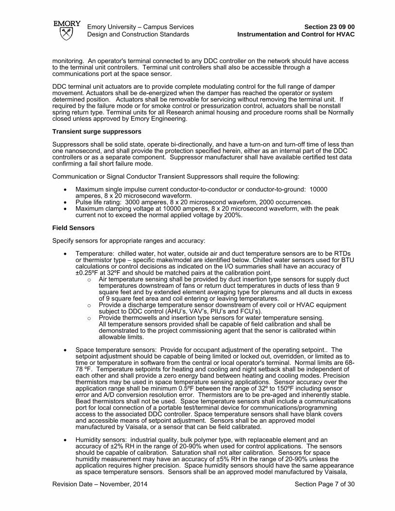
Emory University – Campus Services Section 23 09 00 Design and Construction Standards Instrumentation and Control for HVAC
Revision Date – November, 2014 Section Page 7 of 30
monitoring. An operator's terminal connected to any DDC controller on the network should have access to the terminal unit controllers. Terminal unit controllers shall also be accessible through a communications port at the space sensor. DDC terminal unit actuators are to provide complete modulating control for the full range of damper movement. Actuators shall be de-energized when the damper has reached the operator or system determined position. Actuators shall be removable for servicing without removing the terminal unit. If required by the failure mode or for smoke control or pressurization control, actuators shall be nonstall spring return type. Terminal units for all Research animal housing and procedure rooms shall be Normally closed unless approved by Emory Engineering. Transient surge suppressors Suppressors shall be solid state, operate bi-directionally, and have a turn-on and turn-off time of less than one nanosecond, and shall provide the protection specified herein, either as an internal part of the DDC controllers or as a separate component. Suppressor manufacturer shall have available certified test data confirming a fail short failure mode.
Communication or Signal Conductor Transient Suppressors shall require the following:
• Maximum single impulse current conductor-to-conductor or conductor-to-ground: 10000 amperes, 8 x 20 microsecond waveform.
• Pulse life rating: 3000 amperes, 8 x 20 microsecond waveform, 2000 occurrences. • Maximum clamping voltage at 10000 amperes, 8 x 20 microsecond waveform, with the peak
current not to exceed the normal applied voltage by 200%. Field Sensors Specify sensors for appropriate ranges and accuracy:
• Temperature: chilled water, hot water, outside air and duct temperature sensors are to be RTDs or thermistor type – specific make/model are identified below. Chilled water sensors used for BTU calculations or control decisions as indicated on the I/O summaries shall have an accuracy of ±0.25ºF at 32ºF and should be matched pairs at the calibration point.
o Air temperature sensing shall be provided by duct insertion type sensors for supply duct temperatures downstream of fans or return duct temperatures in ducts of less than 9 square feet and by extended element averaging type for plenums and all ducts in excess of 9 square feet area and coil entering or leaving temperatures.
o Provide a discharge temperature sensor downstream of every coil or HVAC equipment subject to DDC control (AHU’s, VAV’s, PIU’s and FCU’s).
o Provide thermowells and insertion type sensors for water temperature sensing. All temperature sensors provided shall be capable of field calibration and shall be demonstrated to the project commissioning agent that the senor is calibrated within allowable limits.
• Space temperature sensors: Provide for occupant adjustment of the operating setpoint.. The setpoint adjustment should be capable of being limited or locked out, overridden, or limited as to time or temperature in software from the central or local operator's terminal. Normal limits are 68-78 ºF. Temperature setpoints for heating and cooling and night setback shall be independent of each other and shall provide a zero energy band between heating and cooling modes. Precision thermistors may be used in space temperature sensing applications. Sensor accuracy over the application range shall be minimum 0.5ºF between the range of 32º to 150ºF including sensor error and A/D conversion resolution error. Thermistors are to be pre-aged and inherently stable. Bead thermistors shall not be used. Space temperature sensors shall include a communications port for local connection of a portable test/terminal device for communications/programming access to the associated DDC controller. Space temperature sensors shall have blank covers and accessible means of setpoint adjustment. Sensors shall be an approved model manufactured by Vaisala, or a sensor that can be field calibrated.
• Humidity sensors: industrial quality, bulk polymer type, with replaceable element and an
accuracy of ±2% RH in the range of 20-90% when used for control applications. The sensors should be capable of calibration. Saturation shall not alter calibration. Sensors for space humidity measurement may have an accuracy of ±5% RH in the range of 20-90% unless the application requires higher precision. Space humidity sensors should have the same appearance as space temperature sensors. Sensors shall be an approved model manufactured by Vaisala,

Emory University – Campus Services Section 23 09 00 Design and Construction Standards Instrumentation and Control for HVAC
Revision Date – November, 2014 Section Page 8 of 30
or a sensor that can be field calibrated.
• Pressure sensors: Designed for media sensed and for static or differential pressure measurement, as appropriate. The sensor should be capable of withstanding an overrange pressure limit of 300% of the normally expected value. Sensor should incorporate a transducer with non-interacting zero and span adjustments. The span shall be continuously adjustable from 0 to 125% of the expected full pressure or full flow differential pressure. The zero shall be continuously adjustable on outputs. Acceptable manufacturer for static and differential pressure measurement is Setra Sensing Solutions. Contractor shall coordinate with mechanical contractor water differential meters to include high and low line isolation valves and parallel pressure gage piped to read high and low pressures independently.
• Water flow meters: turbine, insertion type, with isolation valve and packing gland for removal
under full line pressure. Wetted parts shall be corrosion-resistant. Range shall be selected to match the application, with sufficient flow velocity to assure accurate measurement at both the low and high expected values. Accuracy should be ±3% at any operating point within this range.
• Current sensing relays: current sensing relays shall provide a normally open contact rated at a
minimum of 50V peak and 0.5 amperes or 25 VA with an adjustable setpoint. There shall be a single opening for passage of current carrying conductors. Relays shall be sized for operation at 50% rated current based on the connected load. Voltage isolation shall be a minimum of 600V. Current sensing relays shall be split core type wherever possible.
• Filter status: Filter replacement at Emory is accomplished on a regular PM program, therefore
filter status will generally not be a requirement. However, this shall be determined on a project specific basis. Where used, filter status shall be sensed by contact closures or 4-20 mA input from differential pressure gauges across each filter. Instrumentation should be specified with the filter assemblies in the appropriate section and the interface signal requirement coordinated between that section and the DDC controls. Requirement should be indicated on the Input/Output Summary.
• Air Quality: [Verify with Engineering Services the use of Air Quality sensors] For spaces with
variable people loads or high outside air requirements, include either an interface to occupancy sensors or air quality sensors to vary outside air requirements and/or terminal unit air flow minimums.CO2 sensors shall be dual channel infrared type, with 10 micron filter to prevent particulate contamination of sensing element. Sensor shall have an accuracy of ±5% of reading up to 10000 ppm, with a repeatability of ±20 ppm and a maximum drift of ±10 ppm per year, and a recommended calibration interval of 5 years. Sensor shall have a response time of no more than 2 minutes to a 90% of full scale change. Sensor and transmitter shall provide a 4-20 mA analog output proportional to gas concentration and a relay output indicating sensor setpoint has been exceeded. Manufacturer: Engelhard Corporation, Veris, or Tel-Aire
• Safety/Limit devices
o Low Temperature Limit – provide hard wired safety function interlock to equipment starter. Provide additional dry contact for monitoring by the DDC system. Low temperature detection shall be present in every square foot of the coil or duct it is protecting.
o High Temperature Limits – provide hard wired safety function interlock to equipment starter. Provide additional dry contact for monitoring by the DDC system.
o Low and High Static pressure Limit – provide hard wired safety function interlock to equipment starter for each side of fans over 2,000 CFM. Provide additional dry contact for monitoring by the DDC system.
o High Humidity Limit – provide hard wired safety function interlock to humidifier control valve. Provide additional dry contact for monitoring by the DDC system.
o End Switch – provide hard wired safety function interlock to equipment starter. End Switch shall be secured to shaft of equipment being monitored to provide actual status of equipment. Integral end switches to actuators shall not be permitted. Provide additional dry contact for monitoring by the DDC system.
o Flow Switch – provide hard wired safety function interlock to equipment starter. Provide additional dry contact for monitoring by the DDC system. Use of non magnetic flow switches is preferred.
Control Devices
• Control valves: brass-trimmed; 2" and smaller, bronze bodies with screwed connections; over 2",

Emory University – Campus Services Section 23 09 00 Design and Construction Standards Instrumentation and Control for HVAC
Revision Date – November, 2014 Section Page 9 of 30
cast iron bodies with flanged connections. Steam valves operating at pressure differentials greater than 25 psi and water valves operating at pressure differentials greater than 40 psi shall have stainless steel trim and replaceable seat ring.
o Valves shall be capable of full closure against 150% of design pump head, or a 50 psig (gauge) differential pressure, whichever is greater.
o Valves for water shall have equal percentage flow characteristics. Modulating control valves shall be sized for a pressure drop of 3 to 5 psi, unless indicated otherwise on the Drawings. Two-position valves shall be line size.
o Ball valves used for modulating service shall have a replaceable flow characterizing disk to provide the required flow characteristics.
o Steam valves shall have linear characteristics. o At the Contractor's option, control valves may be butterfly type for chilled and condenser
water service in piping 2" and larger. Modulating butterfly valves shall be sized for required flow at 60 degrees opening with a pressure drop of 2-4 psi. Two-position control valves shall be line size. Valves 8" and larger shall be provided with either worm-gear electric actuators or high pressure pneumatic actuators sized for 150% of the torque required to unseat the valve from the closed position. Valves shall be rated for bubble tight closure at a differential pressure equal to the valve body rating.
• Temperature regulators, self-contained: adjustable type with enclosed bellows, cadmium-plated
spring, indexed spring adjustment guide, top mounted 3.5" diameter temperature indicator, sensing bulb and copper plastic-covered Teflon-covered capillary tubing. Capillary length shall be as required for the installation. Valves up to 2" shall have bronze body, screw pattern, and stainless steel trim, and shall be rated for 150 psig (gauge) service. Valves 2.5" to 6" shall have cast iron body, 125 psig (gauge) flanges, and stainless steel trim.
• Control dampers: single-blade up to 8" high, multiblade over 8" high; minimum 80% free area
based on damper frame outside dimensions.
o Blades: minimum 16 gauge galvanized steel, or extruded aluminum. Blades shall be airfoil shape.
o Pivot rods: steel, minimum 0.5" diameter or hex, with one rod extended 6" to permit operation of damper from outside the duct.
o Maximum length 42"; maximum width 8". o At points of contact: interlocking or overlapping edges, and compressible neoprene or
extruded vinyl blade seals, and compressible metal side seals designed for temperature of –40ºF to 180ºF at leakage rate specified herein.
o Type: Opposed blade: for balancing and modulating applications. Parallel blade: for 2-position, and outside and return air mixing applications. For
mixing applications, orient dampers to achieve maximum mixing at throttled conditions.
o Maximum damper area per motor: 15 square feet. o Leakage when closed: less than 4 cfm per square foot at 1" wg differential static
pressure based on a 48" damper width. o Frames: galvanized steel bar minimum 2" x 12 gauge for dampers 10" high or less, and
3.5" x 16 gauge galvanized roll-formed channel with double-thickness edges or 5" x 1" x 0.125" extruded aluminum channel for 11" high and larger.
o Corner bracing - Full size of duct or opening in which installed. o Bearings: bronze sleeve, steel ball type, or Cycoloy 800. o Thrust bearings: vertically mounted. o Maximum spacing: 42". o Finish on steel parts: galvanized. o Operating linkage: factory-assembled, concealed in frame out of airstream, steel
construction.
• Actuators: o Include the requirement for spring return if a definite position is required for failure mode
or a smoke control system. o Siemens systems shall install Siemens brand actuators or actuators manufactured by
and carry the name brand Belimo. o ALC systems shall install actuators manufactured by and carry the name brand Belimo. o DDC terminal unit actuators: nonstall spring return type, providing complete modulating
control for the full range of damper movement. Actuators shall be de-energized when the
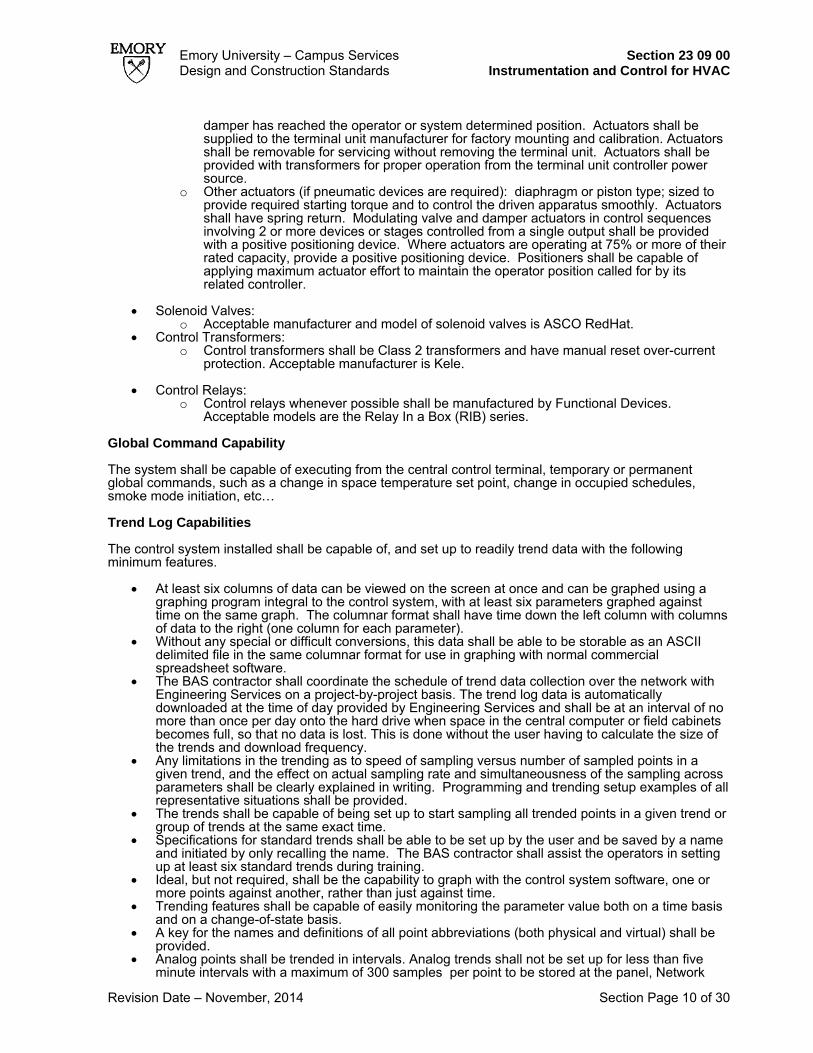
Emory University – Campus Services Section 23 09 00 Design and Construction Standards Instrumentation and Control for HVAC
Revision Date – November, 2014 Section Page 10 of 30
damper has reached the operator or system determined position. Actuators shall be supplied to the terminal unit manufacturer for factory mounting and calibration. Actuators shall be removable for servicing without removing the terminal unit. Actuators shall be provided with transformers for proper operation from the terminal unit controller power source.
o Other actuators (if pneumatic devices are required): diaphragm or piston type; sized to provide required starting torque and to control the driven apparatus smoothly. Actuators shall have spring return. Modulating valve and damper actuators in control sequences involving 2 or more devices or stages controlled from a single output shall be provided with a positive positioning device. Where actuators are operating at 75% or more of their rated capacity, provide a positive positioning device. Positioners shall be capable of applying maximum actuator effort to maintain the operator position called for by its related controller.
• Solenoid Valves:
o Acceptable manufacturer and model of solenoid valves is ASCO RedHat. • Control Transformers:
o Control transformers shall be Class 2 transformers and have manual reset over-current protection. Acceptable manufacturer is Kele.
• Control Relays:
o Control relays whenever possible shall be manufactured by Functional Devices. Acceptable models are the Relay In a Box (RIB) series.
Global Command Capability The system shall be capable of executing from the central control terminal, temporary or permanent global commands, such as a change in space temperature set point, change in occupied schedules, smoke mode initiation, etc… Trend Log Capabilities The control system installed shall be capable of, and set up to readily trend data with the following minimum features.
• At least six columns of data can be viewed on the screen at once and can be graphed using a graphing program integral to the control system, with at least six parameters graphed against time on the same graph. The columnar format shall have time down the left column with columns of data to the right (one column for each parameter).
• Without any special or difficult conversions, this data shall be able to be storable as an ASCII delimited file in the same columnar format for use in graphing with normal commercial spreadsheet software.
• The BAS contractor shall coordinate the schedule of trend data collection over the network with Engineering Services on a project-by-project basis. The trend log data is automatically downloaded at the time of day provided by Engineering Services and shall be at an interval of no more than once per day onto the hard drive when space in the central computer or field cabinets becomes full, so that no data is lost. This is done without the user having to calculate the size of the trends and download frequency.
• Any limitations in the trending as to speed of sampling versus number of sampled points in a given trend, and the effect on actual sampling rate and simultaneousness of the sampling across parameters shall be clearly explained in writing. Programming and trending setup examples of all representative situations shall be provided.
• The trends shall be capable of being set up to start sampling all trended points in a given trend or group of trends at the same exact time.
• Specifications for standard trends shall be able to be set up by the user and be saved by a name and initiated by only recalling the name. The BAS contractor shall assist the operators in setting up at least six standard trends during training.
• Ideal, but not required, shall be the capability to graph with the control system software, one or more points against another, rather than just against time.
• Trending features shall be capable of easily monitoring the parameter value both on a time basis and on a change-of-state basis.
• A key for the names and definitions of all point abbreviations (both physical and virtual) shall be provided.
• Analog points shall be trended in intervals. Analog trends shall not be set up for less than five minute intervals with a maximum of 300 samples per point to be stored at the panel, Network

Emory University – Campus Services Section 23 09 00 Design and Construction Standards Instrumentation and Control for HVAC
Revision Date – November, 2014 Section Page 11 of 30
collected trend data will be kept on the server for 30 days. • Analog points shall not be trended based on Change of Value unless required and approved by
Engineering Services. • Digital point trends shall only be configured for Change of Value with a maximum of 300 samples
per point to be stored at the panel. Network collected trend data will be kept on the server for 30 days.
• Digital points shall not be trended based on intervals unless required and approved by Engineering Services
• The BAS contractor shall ensure that any trend data needed for longer than thirty days is properly archived in reports and scheduled to be automatic at a time of day provided by Engineering Services.
Data Collection and Reporting Project documents must define the data collection and reporting required of the project. Coordinate these requirements with the Emory Project Manager, Commissioning Engineer, Controls Engineer and Energy Utility Engineer for each project. Part 3 – Execution Requirements Construction Schedule During construction a default schedule of 5 a.m. to 5 p.m. should be used with the system off/on, weekends, and holidays. An exception to this is allowed for paint drying and carpet off gassing. DDC Panel Installation Wire controllers, relays, switches, and controls in the control panel to a terminal block. Line voltage and low voltage shall be separated on different terminal blocks with labels indicating voltage. Each sensor or other electrical device shall be wired back to the terminal block in the control panel. Devices in series shall be individually terminated at the terminal block, such that each side of each device is available at the control panel for troubleshooting. In addition to number markings on each conductor, conductor color shall be the same throughout each wiring run. Wiring shall be neatly tied and routed in the control panel. Shielded wiring shall be terminated neatly, with heat shrink tubing placed over the bare end of the shield. Ground conductors over 4" long shall be insulated with tubing. DDC panel installation shall include 120V duplex convenience outlet wired from the same circuit as the DDC controller. Each item in the panel shall be labeled with nameplates or tags bearing the functional designations shown on approved control diagrams. Each control panel shall be labeled to identify the system or equipment served and to identify the location and circuit designation of the electrical power source. Panels shall be located to avoid conflicts with ductwork, piping, equipment, the work of other trades, and building conditions. Panel locations indicated on the Drawings shall be coordinated prior to installation and adjusted to avoid conflicts. Sensor Installation All sensor installations shall be labeled with nameplates or tags bearing the functional designations shown on approved control diagrams. Temperature Sensors:
• Mount space condition sensors at the following heights, aligned vertically or horizontally with adjacent light switches or, if no light switch, with receptacles:
Adjustable 48" above the floor Concealed adjustment 60" above the floor
Concealed setpoint adjustment type space temperature sensors that have occupant override push buttons shall be classified as adjustable type devices. Coordinate final location with the furniture layout and the architectural layout.

Emory University – Campus Services Section 23 09 00 Design and Construction Standards Instrumentation and Control for HVAC
Revision Date – November, 2014 Section Page 12 of 30
• Align vertically or horizontally with adjacent light switches or, if no light switch, with receptacles.
Coordinate final location with the furniture layout and the architectural layout. • Remote element type: mount on a vibration free surface 5' above the floor, unless specified
herein to be mounted on a control panel. Where installed at a coil or in a duct, provide 1 linear foot of element to sense the temperature of each square foot of the coil face. Install in a serpentine arrangement across the entire face of the coil.
• Averaging and low limit safety type elements: install in a horizontal sine curve manner to sense
temperatures across the entire face of the coil, and support independently from the coil by stainless steel bands or multibulb holders. Provide 1 linear foot of element for each square foot of coil area. Provide 0.5" metallic raceway or 0.375" hard copper rails for support of elements, both top and bottom, for plenum or duct width greater than 36".
• Under window fan-coil unit thermostats: mount so that adjusting knob is accessible through
access panel. • Provide guards on thermostats and space temperature sensors in warehouses, gymnasiums,
storage rooms and equipment rooms. • Provide insulated bases for thermostats and temperature sensors installed on exterior walls or
walls to unconditioned spaces. • Provide sealed bases were wall mounted devices mount to walls that produce negative pressure
relationships such as a lab space with a negative offset requirement. • Liquid temperature sensors: fill sensor wells with thermally conductive material to assure
accurate readings. Current sensing relays: fan and pump status shall be sensed by a current sensing relay wired on the load side of each fan and pump. For constant speed fans and pumps, the current sensing relay trip setpoint shall be set at 10% below the motor's normal operating speed and corresponding current draw. For variable speed fans and pumps, the current sensing relay trip setpoint shall be set 5% below the lowest operating speed and corresponding current draw, as determined by the commissioning process (typically 20%). Static Pressure Sensors: Install sensors in the associated air handling unit control panel and use extended sensing lines. Sensor may be installed in field if location is approved prior to installation and is determined to be easily accessible. Provide taps for calibration purposes (barbed tee adapter at a minimum at each sensor). Hydronic Pressure Sensors: Coordinate with mechanical contractor to install sensors adjacent to measurement points, with sensing lines extended to accessible locations. Mechanical contractor to provide test points equipped with Schrader valves in each sensing line for calibration purposes. Sensor piping shall be copper or brass. Steel or black iron shall not be permitted. Sensor piping shall be tapped from the sides of the main pipes being measured. Taps shall not be from the top as this could trap air. Taps shall not be from the bottom as this could catch debris and clog the sensor piping. Meter Installation- See section 23 05 19 Sensor Piping Tubing shall be concealed except in mechanical rooms Tubing installed inside control panels and equipment enclosures, and above ceilings shall be tied and supported. Fasten tubing with clips at regular intervals and run parallel to building lines. Attach concealed tubing above suspended ceilings to structure or ductwork supports. Nonmetallic tubing run in mechanical rooms and concealed in inaccessible locations shall be run in metallic raceways. Make connections to hot equipment with copper tubing.

Emory University – Campus Services Section 23 09 00 Design and Construction Standards Instrumentation and Control for HVAC
Revision Date – November, 2014 Section Page 13 of 30
Copper bends shall be tool made. Provide unions at final connections to apparatus. Provide separation between dissimilar metals. Test tubing at 30 psig (gauge) for pressure loss of not more than 1 psi in 1 hour. Sensor and Meter Calibration Calibration of DDC sensors and metering devices shall be included as part of the pre-functional checklists according to the following procedures and shall be verified during the Functional Testing of the commissioning process:
General: verify that sensors with shielded cable are grounded only at one end.
Sensors without external transmitters: take a reading with a calibrated test instrument within 6"of the sensor installation and verify the sensor reading is within the specified tolerance. If not, install offset, calibrate, or replace sensor to obtain required accuracy.
Sensors with external transmitters: disconnect sensor from transmitter input and connect a signal generator in place of sensor. Using manufacturer's data, simulate minimum measured value. Adjust transmitter potentiometer zero until minimum signal is read. Repeat for the maximum measured value and adjust transmitter until maximum signal is read. Reconnect sensor. Make a reading with a calibrated test instrument within 6" of the sensor installation. Verify that the sensor reading is within the specified tolerance. If not, repeat the process until specified accuracy is achieved, or replace the sensor and repeat process.
Paired sensors: for sensor pairs that are used to determine a temperature or pressure difference, calibrate both sensors to a common measurement and verify they are reading within ±0.25ºF for temperature and within a tolerance equal to ±2% of the sensor reading for pressure.
Proper calibration of sensors shall be demonstrated and documented as part of the commissioning process.
Thermometers Provide at each remote temperature sensor and element location. Do not duplicate thermometers specified in other Sections. Mount thermometers in piping, ducts, and equipment in positions adjusted to be accessible for reading. Use angle and adjustable types where straight type would not be readable. Fill thermometer wells with thermally conductive material. Control Dampers For outdoor air damper assemblies, stage the opening of each section to prevent stratification and poor mixing of outside and return air. Control Valves Valves shall be installed to use the full range of the modulating control signal to position the valve through its full range of travel. Emory discourages the use of pneumatic valves on all but the largest equipment. Where applicable provide high pressure air and connecting piping for valve actuators. Coordinate with the mechanical contractor location of PT plugs or pressure measurement taps, equipped with Schraeder valves, before and after each modulating control valve. The use of pressure independent chilled water control valves are required for air handlers in buildings connected to a chiller plant. Manufacturers should be Flow Control, Bray, Belimo or Danfoss. Pressure independent control valves are not required in fan coil units. Wiring Materials and installation of wiring and electrical devices shall be in accordance with NFPA 70-2002, and

Emory University – Campus Services Section 23 09 00 Design and Construction Standards Instrumentation and Control for HVAC
Revision Date – November, 2014 Section Page 14 of 30
Division 23. [Engineer - Choose 1 of the following 2 paragraphs. Allowing plenum cable can save cost but must be acceptable to the Owner. Plenum cable can be easily damaged and is difficult to get installed in a neat manner. Get Owner's approval before deciding]:
1 - Control and sensor wiring shall be installed in conduits and shall be separate from ac wiring of any voltage. Conduits to devices in finished spaces shall be concealed.
2 - Exposed control and sensor wiring shall be installed in conduits and shall be separate from power wiring. Plenum rated cable may be used in concealed spaces if run parallel to structural grid and supported by cable trays or tie wraps, and identified in a manner consistent with the documentation of the system every 30'. Conduits to devices in finished spaces shall be concealed.
Provide control transformers or filters for operation of automatic temperature controls from building power circuits. Provide control relays, control transformers, control fuses and interlock wiring as required to accomplish the sequences specified herein. Wiring for emergency fan shutdown from fire alarm system and manual stations shall be separate from control and sensor wiring and devices. [Engineer – Regarding the following requirement - Coordinate the availability of electric circuits for DDC controllers, terminal unit controllers, and other power consuming devices. Specific circuits should be identified on the Electrical Drawings. These circuits should be extended to specific locations shown on the Drawings and terminated in j-box enclosures for the DDC system’s use.]
Provide power wiring to DDC controllers, terminal unit controllers, flow measuring devices, and other power consuming devices of the DDC control system from adjacent junction box provided, installed, and wired back to electrical distribution panel by others.
[Engineer- Regarding the following requirement - Coordinate the availability of emergency power and the connection of equipment with the Emory Project manager and the HVAC Shop Manager.]
Branch circuit wiring and conduit furnished under this Section for control equipment power shall be separate from other power wiring. Each circuit shall be extended by others to 120V branch circuit panel, and identified 120V, 20 ampere, single-pole branch circuit breaker furnished in the panel to serve the circuit. DDC controllers shall be connected to emergency power circuits if the controlled equipment is connected to emergency power.
Low voltage control and sensor wiring shall be continuous without splicing. Compressed Air Supply [Engineer – Regarding the following requirements - Delete if pneumatic devices are not specified.] Compressed air piping shall comply with requirements specified herein for sensor piping. Main instrument air distribution shall be through high pressure air mains (tank pressure). Air mains shall be extended to each temperature control panel and air handling unit. Minimum line size shall be 0.375"od with a maximum allowable pressure drop, at design air flow, of 10 psig (gauge) to the farthest point. Provide final regulators at each point of use, with isolation valves and gauges for both high pressure and regulated pressure. Provide high pressure to equipment where required for performance specified herein. Provide a valved high pressure connection at each air handling unit for use by the variable volume pressurization controls systems.

Emory University – Campus Services Section 23 09 00 Design and Construction Standards Instrumentation and Control for HVAC
Revision Date – November, 2014 Section Page 15 of 30
Existing copper tubing may be reused at the Contractor's option. Main control air lines to new connections, beginning at the existing air compressors, shall be cleaned with dry nitrogen for moisture removal. If tubing is found to be contaminated with oil, it shall be replaced. Cleaning and reworking of control tubing shall be coordinated with building occupancy requirements. Temporary compressors shall be installed to continue operation of systems where shutdown cannot be scheduled. Provide easily visible and accessible pressure gauges on control air system at each unique actuating mechanism (i.e. if 4 actuators work one damper set, provide only one gauge) Pneumatic gauges are not required for individual terminal unit installations. [Engineer – Regarding the following requirements - Show location on the drawings, and coordinate power with Electrical.]:
A dual desiccant dryer with standby cell shall be provided for exterior pneumatic air piping and devices.
Install a gauge on each controlled device except room thermostats. Gauges may be mounted in or on the control panel if the controlled device is within sight from the panel.
On positive positioning devices, provide gauges for both pilot input and actuator signals.
Hand-Off-Automatic and Controller Bypass Switches Provide hand-off-auto selection switches or override capability for all critical DDC system outputs. These include primary and secondary pumps, research and animal quarters AHU VFD’s and Exhaust fans, Tertiary pumps and other critical user defined equipment. All HOA switches shall generate an alarm on the front end when not in “Auto” mode. Safety devices, including fire alarm system relays and emergency fan shutdown stations, shall be wired in series with the motor controller holding coil circuit and shall be active in the hand and automatic positions and in the bypass position, if appropriate for the installation. Interlocking with other fans, equipment, or systems other than those required for the operation of the specific equipment shall be through automatic positions only. Remote control from the DDC system shall be through automatic positions. Hand position shall be for maintenance operation only. Operation in hand position shall energize associated dampers and equipment necessary to allow operation.
Provide a means for manual adjustment of analog outputs when in the hand position. Sequences Of Operation The following items apply to control sequences specified herein:
Variable Speed Controls:
Variable frequency drives shall start at low speed.
When 2 or more variable speed pumps operate in parallel, their speeds shall be syn-chronized and controlled from a common signal.
Variable frequency drives shall not operate below the minimum speed set on the control panel. Minimum speed setting shall be determined during system commissioning and shall not be lower than the motor manufacturer’s recommendation.
Equipment safeties shall be wired into variable frequency drive control circuits.

Emory University – Campus Services Section 23 09 00 Design and Construction Standards Instrumentation and Control for HVAC
Revision Date – November, 2014 Section Page 16 of 30
Indication of equipment operating status and actuation of control sequences shall be accomplished by current sensing relays unless otherwise indicated in the I/O summaries.
Upon power failure and restoration, systems shall automatically restart and return to their normal mode of operation. Adjustable time delays shall be provided to sequentially stage starting of equipment with motors greater than 5 hp or electric heating loads greater than 4 kW.
Controls shall fail as specified herein, or to minimize possibility of damage on failure if not specified herein.
Control setpoints shall be adjustable over the range of the sensed media. Means of adjustment and current setpoint shall be identified. DDC setpoints and alarm limits shall be programmed as variables, expressed in the appropriate engineering units, which can be adjusted through the digital display unit or from a central station without requiring modification or reloading of the DDC control programs. Control, alarm, and limit setpoints for each DDC controller shall be displayed and shall be adjustable from an appropriately password-protected tabular graphic display associated with the appropriate equipment. Setpoints or alarm limits common to multiple control algorithms shall be configured as a common variable, requiring a single adjustment.
Control outputs shall provide maximum rated actuator power at extremes of actuator travel. Control output range (0-100%) shall correspond to actuator travel (0-100%).0% shall indicate closed or zero speed output to device, whereas 100% shall indicate completely open or full speed to device.
Where dampers prevent airflow through an air handling unit or fan, those dampers shall be proven open prior to starting the unit or fan. Proof shall be by mechanical safety limit switch activated by the damper blade. This switch shall be installed on the damper shaft and wired in the automatic and hand/test positions, and in variable speed bypass position, if applicable. End Switches integral to actuators are not acceptable.
Interface with existing systems, if required, shall be as follows:
Existing thermostats serving existing terminal units shall be removed and new devices installed as indicated on the Drawings. Verify operation of existing terminal unit controls associated with new or relocated thermostats and advise the Emory Project Manager of any malfunctions.
New terminal units installed in existing systems shall function as follows:
Dual duct - a room thermostat shall position the mixing valves to maintain room temperature.
Constant volume reheat - a room thermostat shall modulate the 2-way hot water coil valve.
VAV – a room thermostat shall modulate the supply air volume between the maximum and minimum flow volumes to maintain room temperature.
Alarms Alarms shall be implemented as follows and demonstrated to Emory and/or the Commissioning Consultant prior to turn-over to Emory.
Alarms shall only print to the approved alarm screen destinations specific to type of alarm and the workstation that is determined to receive those types. The BAS contractor shall coordinate with Engineering Services on a project-by-project basis.
Alarms that print to the alarm screen as well as annunciate graphically:
• Motor status – (DO vs. DI) • Low / High exhaust static pressure • VFD fault • Environmental room temp

Emory University – Campus Services Section 23 09 00 Design and Construction Standards Instrumentation and Control for HVAC
Revision Date – November, 2014 Section Page 17 of 30
• IT and/or Server room temp • Leak detectors • The following alarms are based on need determined by Emory. The control vendor shall confirm
in writing to Emory where to implement the following: o Zone temperature o Zone humidity o Zone volumetric offset o Zone pressure offset o Fume hood monitors
Alarms that annunciate graphically:
• Low / High airflow (Any airflow that is controlled to a setpoint) • High CO2 • Fire Alarm Relay • Low / High humidity (Any humidity that is controlled to a setpoint) • ERU wheel rotation alarm • Low / High building static pressure that is controlled to a setpoint • High static pressure safety switch • Low static pressure safety switch • Low / High mixed air static pressure that is controlled to a setpoint • Low / High supply static pressure • High temperature cut-out • Low temperature cut-out • Low / High temperatures (Unit supply, Preheat discharge, Mixed air temp, Hot Water supply, etc.,
that are controlled to a setpoint.) • Low / High water differential pressure
Alarms associated with animal rooms shall be reviewed and agreed by Emory’s Department of Animal Resources. The system shall be capable of contacting individual occupants as defined per project with notification alarms contacting via phone, text and/or email. These areas are not typical and will be handled on a case by case basis specific to individual rooms and equipment. Graphics The control vendor shall provide Emory approved graphics as described herein. In general the following shall be provided:
• Graphic screens shall be sized to fit 1024x1280 screen size. • Graphic displays for systems and system components shall be provided as indicated in the
approved control submittal. • The operator shall be capable, upon command entry, of calling for graphic displays of building
floor plans, systems, or temperature control zones. • Displays shall include scaled building floor plans with air handling unit and terminal unit
temperature control zones identified by color coding, terminal unit name, actual physical location of terminal units, and space sensors indicated. [Refer to example of floor plan graphic included in the back of this section]. The serving AHU or AHU’s shall be indicated on each floor plan graphic and the area or terminal units they serve shown.
• Graphic floor plans shall incorporate the final approved room numbering. Do not use point naming that entails room numbers as they are subject to change.
• Graphic floor plans shall indicate the location of hydronic differential pressure transmitters and duct static pressure sensors.
• Displays shall indicate values or status of I/O points associated with that system and those shall be dynamically updated at least once every 30 seconds. Displays shall include current measured values and operating setpoints, as appropriate for the equipment being displayed.
• Displays of outputs shall be arranged and scaled to indicate the actual status, position, or command being sent to the connected device. Displays shall allow the operator to change the operating setpoints of the displayed system or equipment by entering the desired value into a defined portion of the graphic. This revised setpoint shall be transmitted to the appropriate controller and shall become the operating setpoint for the controller. Setpoint modifications from the graphic displays shall be limited by operator access level and by high/low limits established in the controller database.

Emory University – Campus Services Section 23 09 00 Design and Construction Standards Instrumentation and Control for HVAC
Revision Date – November, 2014 Section Page 18 of 30
• Software shall be provided to allow operator modification of graphic displays provided with the system and to allow operator creation and storage of new graphic displays.
• Graphic displays shall be a white or gray background with discrete, solid colors for the graphic elements. Color gradients shall not be used. Text shall be a consistent dark color. Identifiers for digital commandable points shall have a blue or green background to show the commanded state. Analog commandable points shall have a colored background to indicate they are adjustable. Data and reporting points shall have color coded backgrounds to indicate their status or that they are in their normal operating range. Points in an alarm condition shall change to a flashing red text or be displayed in a high contrast color against a flashing red background. No other points shall use this color or a red background.
• Graphic displays shall be basic mechanical system schematics which reflect the actual configuration of the equipment portrayed, with all major components in their correct relative locations. Equipment identifiers, data, and commandable points shall be located adjacent to the graphic element they are associated with. Tabular displays of the equipment data and setpoints shall be used whenever appropriate. If the equipment or system is extensive enough to require multiple graphics to display all required data, individual graphic displays shall contain ALL data required to evaluate the portion being displayed, even if data appears on multiple graphics.
• Graphic displays shall be arranged to correspond to the “flow” of the equipment or system. Graphic and data shall progress in a logical pattern from the entry point of the system to the final delivery point of the system.
• A graphical page shall be linked to and provided for each VAV AHU system that shows all associated terminal unit damper positions and zone temperatures.
• Each facility shall include a main “summary” page. This page shall include: o A picture or architectural rendering of the entry elevation of the building. o A summary of the “status” of the facility and the major systems and equipment. The
location of the status points shall be shown in the general vicinity on the graphic of the installed location of the equipment.
o Links to all major equipment and systems. o Links to each facility floor plan. o A link to the metering and energy consumption information for the facility. o A link to the latest sequence of operation for all controlled and monitored equipment. o A link to a summary of all points in operated or operator-overridden priority.
Examples of graphic screens are provided as attachments to this section. DDC Programming DDC system shall be installed and programmed to accomplish the sequences of operation as defined on the project documents. Programming shall be arranged to allow the “stand-alone” operation of mechanical systems and to minimize the impact of failures of individual controllers and/or communications links. Programming shall be configured such that ALL setpoints, high/low limits, decision points, and other variables in the programming are variables that can be adjusted by an operator with the appropriate access authority through the use of graphic displays. Hard coded variables that require the editing of the actual program code are NOT allowed unless absolutely necessary. Examples of variables not allowed to be hard coded are setpoints and manually tuned PID loop gains. DDC programming code shall include extensive commenting, describing the logic and operation of the code. All internal variables shall be identified in these comments. Equipment responses to fire alarm system signals, as defined by the project documents, shall be independent of the DDC controller and its outputs. As defined by the project documents, secondary responses to these signals or responses of other associated equipment MAY be accomplished through the DDC system and programming. DDC controls and interfaces shall be arranged so that equipment controlled by the DDC system operates as indicated on the I/O summaries on failure of the DDC controller for any reason, including logic power supply failure, CPU lock-up, or interposing relay failure. Safety and operational interlocks shall remain in effect. DDC System Start-Up and Checkout

Emory University – Campus Services Section 23 09 00 Design and Construction Standards Instrumentation and Control for HVAC
Revision Date – November, 2014 Section Page 19 of 30
Provide the services of control technicians at start-up to check-out the system, verify and calibrate sensors and outputs, input data supplied by the Owner and place the system in operation. Verify proper operation of each item in the sequences of operation, including hardware and software. Check-out each system for control function through the entire sequence. Check actuator travel on dampers and valves for action and extent. Verify that control dampers and valves open and close completely. Check calibration of instruments. Calculate and verify instrument setpoints. Calibration and testing: calibrate sensors and monitoring inputs and verify proper operation of outputs before the system is placed on-line. Check each point within the system by making a comparison between the operator console and field device. DDC control loops, failure modes, interlocks, sequences, energy management programs, and alarms shall be debugged, tested, and stable operation verified. Control loop parameters and tuning constants shall be adjusted to produce accurate, stable control system operation. Before obtaining permission to schedule the functional test, provide written documentation of system calibration and certification that the installed complete system has been calibrated, verified, and is ready to begin testing. Specific to Siemens systems, confirm all “Initial Values” saved in the control database are per the design and/or commissioned requirements, and that no value is saved in an operated or overridden state. Refer also to the requirements below regarding “Pre-functional tests”. Commissioning Support Requirements The commissioning process is vital to the Emory project close-out and acceptance process. The involvement and support of the controls contractor is vital to the success of the process. As a result, the project specifications must include the expectations and obligations of the controls contractor in support of the commissioning effort. The project specific expectations will be developed by the CxA, and will generally follow the requirements in Section 01 91 13 – General Commissioning Requirements. The following are specific requirements to the general requirements listed in Section 01 91 13:
• The contractor is to include the cost of CxA support in the contract price. • Preparation of a written start-up and initial checkout plan indicating in a step-by-step manner the
procedures that will be followed to test, check-out, and adjust the control system prior to beginning functional testing. Submit the proposed plan to the Commissioning Authority for review and approval prior to startup.
• Provide the Commissioning Authority complete system logic diagrams, describing the proposed system programming, with programmed attributes shown. These diagrams shall be updated with field modifications from the start-up, check-out, and pre-functional testing prior to the beginning of the functional testing of the DDC system. Provide a copy of each proposed graphical interface screen with interface points shown for the entire system. Provide assistance to the Commissioning Authority in preparing the specific functional performance test procedures required, to include normal cut sheets and shop drawing submittals of commissioned equipment and any additional requested documentation, prior to normal O&M manual submittals. Review test procedures to ensure feasibility, safety and equipment protection and provide necessary written alarm limits to be used during the tests.
• Pre-functional tests: Verify and document the proper installation, addressing, calibration, programming, operation, and failure mode of DDC control points, sequences, and equipment and provide a copy to the commissioning authority. Provide a signed and dated certification to the Commissioning Authority upon completion of the check-out of each controlled device, equipment, and system that installation, set-up, adjustment, calibration, and system programming is complete and as indicated on the Drawings, except functional testing. Completed pre-functional documentation of the system verification shall be submitted to the Commissioning Authority and Commissioning Supervisor for review and approval prior to the functional testing of the DDC control system or its being used in the testing of other equipment or systems, or other purposes. Copies of final field check-out sheets and trend logs shall be provided to the Commissioning Authority for inclusion in the Commissioning Report.
• Meet with the testing, adjusting, and balancing contractor prior to beginning the test, adjustment, and balance process and review the test, adjusting, and balancing plan to determine the capabilities and requirements of the control system in completing the testing, adjusting, and balancing process. Provide the testing, adjusting, and balancing contractor with the appropriate software and any needed unique instruments for setting terminal units and instruct the testing, adjusting, and balancing contractor personnel in their use. Assist and cooperate with the testing, adjusting, and balancing contractor by providing a qualified technician to operate the controls as required to assist the testing, adjusting, and balancing contractor in performing the work, or alternatively, provide sufficient training for the testing, adjusting, and balancing contractor to

Emory University – Campus Services Section 23 09 00 Design and Construction Standards Instrumentation and Control for HVAC
Revision Date – November, 2014 Section Page 20 of 30
operate the system without assistance. Verify the proper operation of affected controls at the completion of the test, adjustment, and balance procedure.
• Address current A/E punch list items before functional testing. Air and water TAB shall be completed with discrepancies and problems remedied before functional testing of the control systems for the respective air- or water-related systems.
• Functional tests: conduct and document a functional test under the direction of the Commissioning Authority of the complete installed DDC control system. Functional testing is intended to begin upon completion of a system but may be conducted in phases or sections, as defined by the requirements of the Functional Test, or as approved by the Commissioning Authority. The DDC system, or applicable portions of the system, shall have completed pre-functional testing and be approved by the Commissioning Authority and Commissioning Supervisor before being used for other purposes, such as test and balance measurements, or in support of the functional testing of other systems.
• Provide technicians and or knowledgeable programming personnel as required to conduct the required functional testing. Assist the Commissioning Authority in resolving issues found during the functional testing process.
• Assist in the functional testing of equipment and systems by implementing trend logs and equipment monitoring as specified in the contract documents. The monitoring and data logging capabilities of the DDC system shall be available for use in the commissioning process. Assist the Commissioning Authority in the testing and documentation process by using the data logging and trending capability of the DDC system in monitoring the testing effort and recording the performance of systems and interpreting the monitoring data, as necessary.
• If the project does not include an operator station, and the building is not connected to the campus network at the time of functional testing for commissioning, the controls contractor shall coordinate with the Emory IT department and provide and set up a temporary testing operator station to allow full operator station interface with the system during the entire functional testing process. This temporary operator station shall provide all functions required of the system at the operator station, including real time graphic displays and report generation.
• Correct deficiencies (differences between specified and observed performance) as interpreted by the Commissioning Authority and Engineer and retest the equipment.
• Seasonal Adjustment: Assist the Commissioning Authority with the seasonal adjustment process. During this effort the Commissioning Authority will test and verify control sequences for proper operation for the season. Where deficient operation or defective equipment is discovered, provide corrective measures as required by the warranty provisions specified herein.
Warranty requirements Execute seasonal or deferred functional performance testing, witnessed by the CxA, according to the specifications. Correct deficiencies and make necessary adjustments to O&M manuals and as-built drawings for applicable issues identified in any seasonal testing. Coordinate with equipment manufacturers to determine specific requirements to maintain the validity of the warranty. DDC System Training Provide a training plan for review 4 weeks before the planned training. The format and training agenda in The HVAC Commissioning Process, ASHRAE Guideline 1-1989R, 1996 is recommended. Training shall occur after functional testing is complete, unless approved otherwise by the Project Manager. Provide training for designated Owner personnel on the control system. The intent is to clearly and completely instruct the Owner on the capabilities of the control system. The training shall be tailored to the needs and skill-level of the trainees. The trainers shall be knowledgeable on the system and its use in buildings. For the on-site sessions, the most qualified trainer(s) will be used. The Owner shall approve the instructor prior to scheduling the training. The standard operating manual for the system and any special training manuals shall be provided for each trainee, with a copy included in each copy of the operation and maintenance manual. In addition, copies of the system technical manual shall be demonstrated during training and a copy included in each

Emory University – Campus Services Section 23 09 00 Design and Construction Standards Instrumentation and Control for HVAC
Revision Date – November, 2014 Section Page 21 of 30
copy of the operation and maintenance manuals. Manuals shall include detailed description of the subject matter for each session. The manuals shall cover control sequences and have a definitions section that fully describes relevant words used in the manuals and in software displays. Training program must include:
• Use of the printed installation, operation and maintenance instruction material included in the O&M manuals.
• A review of the written O&M instructions emphasizing safe and proper operating requirements, preventative maintenance, special tools needed and spare parts inventory suggestions. Training is to include all explanatory information included in the O&M manuals and the location of all plans and manuals in the facility.
• Hands-on training shall include start-up, operation in all modes possible, including manual, shutdown and any emergency procedures and preventative maintenance for all pieces of equipment.
• Common troubleshooting problems and solutions. • Discussion of any peculiarities of equipment installation or operation. • For any controls provided by the control contractor, they shall fully explain and demonstrate the
operation, function and overrides of any local packaged controls, not controlled by the central control system.
• Discussion of relevant health and safety issues and concerns. • Discussion of warranties and guarantees. • Copies of audio-visual materials used in the training program shall be delivered to the Owner, by
the General Contractor Operation and Maintenance Manual Requirements The following O&M manual requirements are the minimum acceptable components for a control system. They should be supplemented as necessary for the requirements of a specific project and coordinated with the general mechanical and project O&M requirements. The controls contractor shall compile and organize at minimum the following data on the control system in labeled 3-ring binders organized and subdivided with permanently labeled tabs. The controls contractor shall also provide an electronic version of the manual to be placed on the controls server. Full set of “As-Built” of control drawings, reflecting all changes made during the construction, checkout, and commissioning process. The “As-Built” drawings must include:
• Accurate scaled floor plans showing the locations of all installed control equipment, sensors, monitoring points, and equipment connected to the DDC control system. Floor plans shall locate any electrical panels that provide power to the system or that are monitored or controlled by it. Space sensors shall be located on these floor plans. Equipment shall be identified on these floor plans by its control system designation.
• A control schematic showing the location of all sensors, monitoring devices, and control outputs, an accurate Bill of Materials identifying the installed equipment, and floor plans showing the installed locations of all control equipment and the locations of electrical panels supplying power to control equipment.
• Full as-built sequence of operations for each piece of equipment, reflecting any changes made to achieve the required system performance.
• Full point list. - An updated points list, identifying all points, actual and virtual, installed in the system. Provide the following information for each point:Point type, Point identifier, Point address
• A listing of all terminal controllers, with the following information for each device: o Associated air handler unit ID and air terminal unit tag ID o Floor, room number, and room name where located and reference drawing number
showing location O Terminal unit tag identification, as implemented in the installed control system. O Heating and/or cooling valve tag identification. O Minimum cfm. O Maximum cfm. o Calibrated flow coefficient.
• Valve Schedule reflecting the actual equipment installed, with the following information for each device: o Floor, room number, and room name where located and reference drawing number
showing location. o Associated coil served and heating and/or cooling valve tag ID
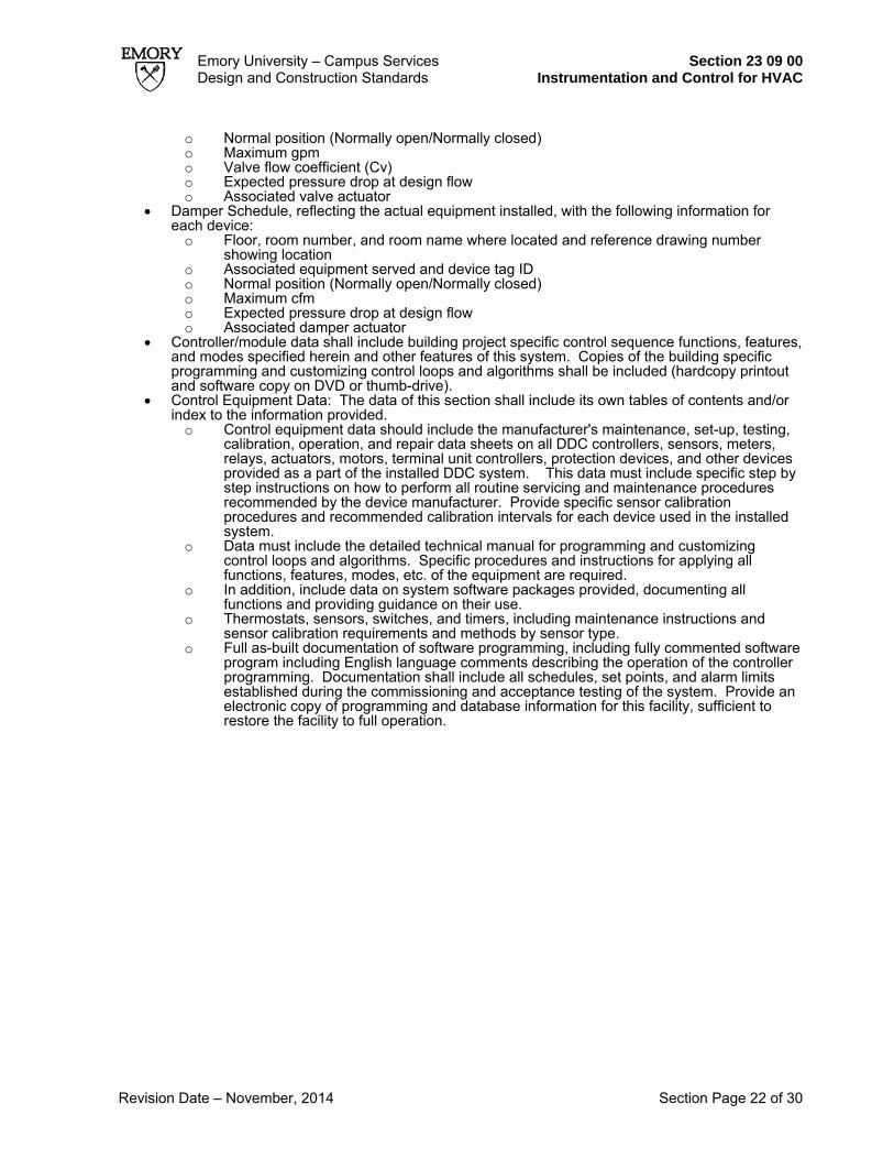
Emory University – Campus Services Section 23 09 00 Design and Construction Standards Instrumentation and Control for HVAC
Revision Date – November, 2014 Section Page 22 of 30
o Normal position (Normally open/Normally closed) o Maximum gpm o Valve flow coefficient (Cv) o Expected pressure drop at design flow o Associated valve actuator
• Damper Schedule, reflecting the actual equipment installed, with the following information for each device: o Floor, room number, and room name where located and reference drawing number
showing location o Associated equipment served and device tag ID o Normal position (Normally open/Normally closed) o Maximum cfm o Expected pressure drop at design flow o Associated damper actuator
• Controller/module data shall include building project specific control sequence functions, features, and modes specified herein and other features of this system. Copies of the building specific programming and customizing control loops and algorithms shall be included (hardcopy printout and software copy on DVD or thumb-drive).
• Control Equipment Data: The data of this section shall include its own tables of contents and/or index to the information provided. o Control equipment data should include the manufacturer's maintenance, set-up, testing,
calibration, operation, and repair data sheets on all DDC controllers, sensors, meters, relays, actuators, motors, terminal unit controllers, protection devices, and other devices provided as a part of the installed DDC system. This data must include specific step by step instructions on how to perform all routine servicing and maintenance procedures recommended by the device manufacturer. Provide specific sensor calibration procedures and recommended calibration intervals for each device used in the installed system.
o Data must include the detailed technical manual for programming and customizing control loops and algorithms. Specific procedures and instructions for applying all functions, features, modes, etc. of the equipment are required.
o In addition, include data on system software packages provided, documenting all functions and providing guidance on their use.
o Thermostats, sensors, switches, and timers, including maintenance instructions and sensor calibration requirements and methods by sensor type.
o Full as-built documentation of software programming, including fully commented software program including English language comments describing the operation of the controller programming. Documentation shall include all schedules, set points, and alarm limits established during the commissioning and acceptance testing of the system. Provide an electronic copy of programming and database information for this facility, sufficient to restore the facility to full operation.

Emory University – Campus Services Section 23 09 00 Design and Construction Standards Instrumentation and Control for HVAC
Revision Date - November, 2014 Section Page 23 of 30

Emory University – Campus Services Section 23 09 00 Design and Construction Standards Instrumentation and Control for HVAC
Revision Date - November, 2014 Section Page 24 of 30

Emory University – Campus Services Section 23 09 00 Design and Construction Standards Instrumentation and Control for HVAC
Revision Date - November, 2014 Section Page 25 of 30

Emory University – Campus Services Section 23 09 00 Design and Construction Standards Instrumentation and Control for HVAC
Revision Date - November, 2014 Section Page 26 of 30

Emory University – Campus Services Section 23 09 00 Design and Construction Standards Instrumentation and Control for HVAC
Revision Date - November, 2014 Section Page 27 of 30

Emory University – Campus Services Section 23 09 00 Design and Construction Standards Instrumentation and Control for HVAC
Revision Date - November, 2014 Section Page 28 of 30

Emory University – Campus Services Section 23 09 00 Design and Construction Standards Instrumentation and Control for HVAC
Revision Date - November, 2014 Section Page 29 of 30

Emory University – Campus Services Section 23 09 00 Design and Construction Standards Instrumentation and Control for HVAC
Revision Date - November, 2014 Section Page 30 of 30

Emory University – Campus Services Section 23 21 23 Design and Construction Standards Hydronic Pumps
Revision Date – November, 2014 Section Page 1 of 1
Section 23 21 23 – Hydronic Pumps 1.01 In-Line Pumps Pumps less than 3 hp shall be mounted in-line and shall be as manufactured by Grundfos or
Bell & Gossett. In-line pumps over 3 hp shall be manufactured by Aurora, Armstrong, Bell & Gossett, Patterson or Taco.
1.02 End Suction Pumps
Mechanical seals shall be used. End suction pumps shall be manufactured by Aurora, Armstrong, Bell & Gossett, Patterson, Peerless or Taco.
1.03 Horizontal Split Case Pumps Mechanical seals shall be used. Typically pumps for services over 25 HP shall be horizontal
split case pumps. Horizontal split case pumps shall be manufactured by Aurora, Patterson, Peerless, Bell & Gossett, Goulds and Taco.
1.04 Vertical Turbine Pumps
Mechanical seals shall be used. Vertical turbine pumps shall be manufactured by Goulds, Bell & Gossett, Peerless or Floway.
1.05 Vibration
To reduce wear and noise, specify that rotating equipment 5 horsepower and larger must be dynamically balanced, tested and measured by the Contractor for displacement in X-Y-Z horizontal, vertical and axial directions. To be acceptable, work shall comply with ISO standards for velocity. Contractor shall provide a report of vibration readings in the closeout documents.
1.06 Pressure gauges
Pressure gauges around the pumps shall be installed with copper tubing (including the manifold used to check DP across pump and strainer). Reference also Section 23-05-00, 1.14 – Test Ports & Gauges.

Emory University – Campus Services Section 23 22 00 Design and Construction Standards Steam & Condensate Specialties
Revision Date – November, 2014 Section Page 1 of 3
Section 23 22 00 – Steam & Condensate Specialties 1.01 Steam Trap Stations
A. Steam trap stations shall be located in steam supply piping locations where appropriate in order to properly drain the condensate from the system. The trap station shall consist of in order: gate valve- strainer- union- steam trap-union-check valve-gate valve. Float and thermostatic trap stations will have a test connection with a steam rated ball valve installed after the steam trap. Install a steam rated ball valve with plug at the strainers. Do not install a bypass line on steam trap stations. Use Float and Thermostatic traps for pressures below 30psi, and Inverted Bucket for pressures 30psi and above. Steam traps shall be manufactured by Armstrong or Sarco.
B. Steam Supply Line Condensate Drip Legs The drip leg will have a dirt leg section, extending below the steam trap station take-off that has blow down line with a steam rated ball valve.
1.02 Steam Pressure Reducing Valves and Safety Valves
A. Steam PRVs shall be manufactured by Spence. All PRV stations, with a final pressure less than 40psig, will use two PRVs in series. In certain cases, two PRVs in parallel are preferred. This is dependent on the type of building and steam flow rates involved. Consult with Engineering Services for approval. When reducing the pressure using two PRV’s in series, use an intermediate pressure of 60psi unless another pressure between 115psi and the final pressure is required for use in the building.
B. Steam safety valve set pressures will be based on the system operating pressure protected by that safety valve. Safety valve set pressures will be 20% or 10psi, whichever is larger, above the system operating pressure. Safety valve capacity will be based on the capacity of the PRV valve directly upstream of the safety valve. A sentinel safety valve (a small capacity valve for failure alert) is required on the intermediate pressure of a two stage pressure reduction station when the intermediate pressure is confined to the PRV station and not used in the mechanical room or facility. Steam safety valves shall be vented to the exterior of the building through an acceptable side wall location or the roof.
C. Emory operates a 150psig rated steam system. PRVs must be rated for maximum operating conditions of at least 150psig.
1.03 Condensate Receivers
All condensate receivers shall be equipped with duplex pumps and shall be vented to the exterior of the building through an acceptable side wall location or the roof. Condensate receivers shall have a full size drain. Piping at the outlet of each pump will include in order union-pressure gauge-circuit setter-check valve and gate valve. Condensate tank accessories will include a sight gauge, temperature well with ¼” insertion temperature gauge, pump suction shutoff valves, inlet basket strainer. Condensate receivers shall be as manufactured by Aurora, Bell & Gossett, Marshall Engineered Products (MEPCO), Peerless, Shipco, or Weinman. If the tank will be recessed into the floor, a minimum 1’ clearance between sides of tank and wall of pit shall be provided.
1.04 Steam Separators
A. Install a steam separator at entrance to building downstream from the building steam shut off valve.
B. Steam separator must be rated for maximum operating conditions of at least 150psig. 1.05 Steam Vacuum Breakers
A. All steam vacuum breakers will consist of a horizontally mounted “T” frame (Crane 1707 or equal) check valve. Spring loaded check valves are not acceptable even when supplied by vendor.
B. Install vacuum breakers on all steam coils and steam heat exchangers. 1.06 Steam Pressure Gages

Emory University – Campus Services Section 23 22 00 Design and Construction Standards Steam & Condensate Specialties
Revision Date – November, 2014 Section Page 2 of 3
A. All steam pressure gauges will mounted on a siphon tube and include an isolation valve. B. Place steam gages in appropriate locations including mechanical room entrances, before and
after PRV valves, before and after control valves. 1.07 Documentation Content
A. Include schedules for PRV valves, safety relief valves and steam traps showing size, capacity and set pressures.
B. Include detail drawings for: • Medium/High Pressure Steam Supply Drip Leg and Steam Trap Station • Low Pressure Steam Supply Drip Leg and Steam Trap Station • Steam Coil Drip Leg and Steam Trap Station • Shell and Tube Heat Exchanger Drip Leg and Steam Trap Station • Steam Condensate Return Tank • We need the detail drawings to include all the information covered in Sections 23 22 00
and 23 57 00 as part of the drawings or as notes listed with each drawing.

Emory University – Campus Services Section 23 25 00 Design and Construction Standards HVAC Water Treatment
Revision Date – October, 2012 Section Page 1 of 7
Section 23 25 00 – HVAC Water Treatment Preoperational Cleaning of Open and Closed Loops 1.0 General The contractor shall coordinate with A&W Technologies to provide chemicals and labor for the pre-operational cleaning of all condenser, chilled, glycol or hot water and related equipment piping systems. This cleaning method is not intended for potable water systems. 2.0 Preparation for Clean-Out All systems must be prepared prior to the introduction of the chemical cleaner.
1. The Contractor shall velocity flush the pipe system prior to the circulation of chemical treatment. A bleed-and-feed flush at a flow rate of 10 feet per second is required. Temporary pumps required to provide the flow velocity shall be provided by the contractor. Contractor shall provide temporary piping connections to form a closed loop piping system to achieve recirculation. Contractor shall provide temporary venting as required to enable full fill of the system. The velocity flush is required only for the steel piping systems. Copper pipe branch lines shall be isolated from the velocity flush. Pipe mains where they transition from steel to copper shall be temporarily disconnected and the steel piping looped for recirculation. A flush consists of moving three times the volume of the system piping through the system at the required flow rate. Two flushes will be required in all cases. Additional flushes are to be accomplished as needed. The system being flushed must be displaced with clean water after each flush.
2. Contractor shall submit a velocity flush plan for review and approval prior to flushing, detailing the requirements above and including information on the pump to be used for the velocity flush.
3. Contractor shall flush all systems, including mud from drop legs. The cooling tower basin must be free of mud, silt and construction debris. Remove, clean and replace all strainers. All systems shall contain the highest quality of water available.
4. Complete circulation must be achieved during the cleaning procedure. A minimum flow rate of 2 ft/sec. needs to be maintained to insure that the cleaning chemicals will work properly. All manual, electrical, air and thermostatic operated valves must be open. All dead end runs must be looped together with piping not less than 1/3 the size of the run. This piping is to remain in place until cleaning is complete.
5. A minimum of 1-1/2" ball or gate valve is to be permanently installed in the low point of each system for the purpose of draining each system.
6. The cleaner shall not require external heat to ensure its effectiveness.
3.0 Chemicals The cleaning solution shall be formulated to remove light grease, cutting oils, loose mill scale, organics and extraneous construction debris. The cleaner shall contain, an organic corrosion inhibitor, a dispersant, and an oil emulsifier. The recommended cleaner shall be A and W Technologies SC 100 and AWC 225. Use AWS-TA10 to prevent any foaming. 1 gallon of SC-100 and AWC 225 per 1000 gallons of system water should be used to treat all of the piping to remove oil and grease and to permit a uniform passivation film to form. This aids in the prevention of flash corrosion when the system is most vulnerable to corrosive attack.
4.0 Pre-Operational Cleaning
1. Cooling tower/Closed system -- maintain lowest water level possible in cooling tower sump or basin.
2. Add recommended quantity of A and W Technologies chemical directly into the tower sump or closed loop system before the recirculating pumps to ensure rapid mixing and distribution throughout the system. A small amount of antifoam (AWS TA10) can be used as needed Refer to MSDS sheets for safety information.

Emory University – Campus Services Section 23 25 00 Design and Construction Standards HVAC Water Treatment
Revision Date – October, 2012 Section Page 2 of 7
3. Recirculate both Closed Loop and Cooling Towers for 24-48 hours. 4. Open and drain mud legs and low points periodically during the cleaning process to sanitary
sewer only. 5. After the cleaning period locate a system drain up stream of the system make up and open
the drain to sanitary sewer only. Allow the system to drain and refill while circulating for 48 hours. A and W Technologies will inspect the system water and verify system contents are equal to make up water. Verifying system flushs success.
6. Upon completion of the flush process all system strainers shall be pulled, cleaned and replaced by contractor.
a. Recharge cooling tower systems with AWC 209, heating water systems with AWC 226, and chilled water systems with AWC 206
7. A service report will be generated by A and W Technologies, certifying that the systems have been cleaned in accordance with the above procedures and shall be copied to the mechanical contractor. A copy of the service report will also be forwarded to the associated Emory University Facilities Management HVAC Shop Supervisor.
Closed Systems 1.0 General Contractor will furnish and install all equipment, chemicals and service necessary to provide a complete Water Treatment Program. A and W Technologies water treatment company shall provide all products and services for undivided responsibility throughout the warranty period. Provide a minimum of 5 days notice for pricing services from A and W Technologies. This company shall have a regional accredited laboratory, research and development facilities, plus technical service representatives located within the trading area of the job site. The water treatment products and services shall be provided by: A and W Technologies 2.0 Chemical Feeding Equipment (Hot/Chilled) For each closed system the contractor shall provide and install the following apparatus (including isolation and drain valves): One (1) – Pot Filter/Feeder with filter, Neptune model #FTF-5. The feeder shall be rated for 200 psi service. Consult A and W Technologies on proper locations. 3.0 Water Treatment Chemicals Furnish a one year's supply of a liquid closed loop inhibitor for control of scale and corrosion in a closed recalculating system. A closed loop is a re-circulating system, which has less than 10% makeup/year when compared to its system volume. A one-year supply of corrosion inhibitor will be provided at start up. Formulations shall not contain any ingredients that may be harmful to system materials of construction. The corrosion inhibitor shall contain a multi-functional blend of tolytriazole, anionic polymer and buffering agent such A and W Technologies AWC 206 for chilled water systems and AWC 226 for hot water systems. Provide MSDS sheets on all chemical products. No system shall be operated without the benefit of chemical protection. Once the recommended chemical residual is achieved, any additional chemicals required to re-treat the system due to water loss or to accomplish other work shall be provided by the Mechanical Contractor. 4.0 Water Treatment Service Program
Provide startup service and monthly service visits to include the following: 1. Installation and system start-up procedures and recommendations. 2. Initial treatment dosages. 3. Training of operating personnel on proper feed and control techniques. 4. Service visits and consultation meetings monthly with General contractor and HVACr Shop. 5. A and W Technologies to record and maintain all necessary logs and records and submit
reports to HVACr Shop on bi-weekly basis. 6. Any required laboratory and technical assistance (as needed).
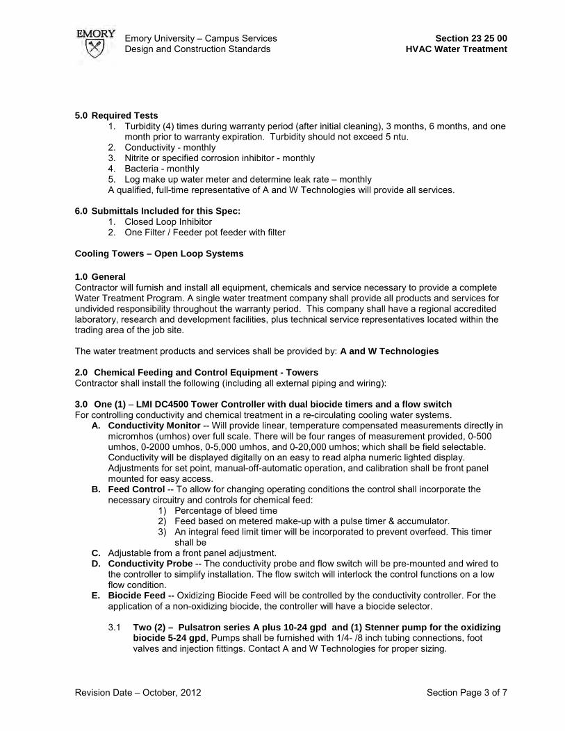
Emory University – Campus Services Section 23 25 00 Design and Construction Standards HVAC Water Treatment
Revision Date – October, 2012 Section Page 3 of 7
5.0 Required Tests
1. Turbidity (4) times during warranty period (after initial cleaning), 3 months, 6 months, and one month prior to warranty expiration. Turbidity should not exceed 5 ntu.
2. Conductivity - monthly 3. Nitrite or specified corrosion inhibitor - monthly 4. Bacteria - monthly 5. Log make up water meter and determine leak rate – monthly A qualified, full-time representative of A and W Technologies will provide all services.
6.0 Submittals Included for this Spec:
1. Closed Loop Inhibitor 2. One Filter / Feeder pot feeder with filter
Cooling Towers – Open Loop Systems 1.0 General Contractor will furnish and install all equipment, chemicals and service necessary to provide a complete Water Treatment Program. A single water treatment company shall provide all products and services for undivided responsibility throughout the warranty period. This company shall have a regional accredited laboratory, research and development facilities, plus technical service representatives located within the trading area of the job site.
The water treatment products and services shall be provided by: A and W Technologies
2.0 Chemical Feeding and Control Equipment - Towers Contractor shall install the following (including all external piping and wiring): 3.0 One (1) – LMI DC4500 Tower Controller with dual biocide timers and a flow switch For controlling conductivity and chemical treatment in a re-circulating cooling water systems.
A. Conductivity Monitor -- Will provide linear, temperature compensated measurements directly in micromhos (umhos) over full scale. There will be four ranges of measurement provided, 0-500 umhos, 0-2000 umhos, 0-5,000 umhos, and 0-20,000 umhos; which shall be field selectable. Conductivity will be displayed digitally on an easy to read alpha numeric lighted display. Adjustments for set point, manual-off-automatic operation, and calibration shall be front panel mounted for easy access.
B. Feed Control -- To allow for changing operating conditions the control shall incorporate the necessary circuitry and controls for chemical feed:
1) Percentage of bleed time 2) Feed based on metered make-up with a pulse timer & accumulator. 3) An integral feed limit timer will be incorporated to prevent overfeed. This timer
shall be C. Adjustable from a front panel adjustment. D. Conductivity Probe -- The conductivity probe and flow switch will be pre-mounted and wired to
the controller to simplify installation. The flow switch will interlock the control functions on a low flow condition.
E. Biocide Feed -- Oxidizing Biocide Feed will be controlled by the conductivity controller. For the application of a non-oxidizing biocide, the controller will have a biocide selector.
3.1 Two (2) – Pulsatron series A plus 10-24 gpd and (1) Stenner pump for the oxidizing
biocide 5-24 gpd, Pumps shall be furnished with 1/4- /8 inch tubing connections, foot valves and injection fittings. Contact A and W Technologies for proper sizing.

Emory University – Campus Services Section 23 25 00 Design and Construction Standards HVAC Water Treatment
Revision Date – October, 2012 Section Page 4 of 7
3.2 One (1) –Seametrics Contacting head Water Meter and cable complete with dry contact register sized to meter the maximum makeup water rate of the system. Or meter specified in the Emory Standards
3.3 Three (3) – Chemical tanks suitable for mounting chemical fed pumps on top surface with secondary containment basins. Material composition shall be white polypropylene. Label shall be placed on secondary container specifying capacity in gallons. Contact A and W Technologies for sizing.
4.0 Water Treatment Chemicals Furnish a one year's supply of the recommended inhibitor and biocide for control of scale, corrosion, and fouling in the open recirculating system. A one year supply of inhibitor, non-oxidizing and oxidizing biocide shall be provided at start up. The inhibitor shall be a multi-functional blend of Organic Phosphate (HEDP), Zinc, Tolytriazole (TT), Dispersant, and molybdenum Tracer to simplify testing and control of the program. The recommended inhibitor shall be traced A and W Technologies AWC 209. The recommended oxidizing biocide shall also be a liquid “stabilized” bromine such as A and W M-93. The recommended non-oxidizing biocide shall be also liquid form such as A and W M-1015. Biocide products recommended shall be properly registered with the Environmental Protection Agency and EPA registration number shall be clearly shown on all product literature and drum labels. To ensure operator safety all chemical products shall be provided in liquid form for direct feed from A and W tank to the cooling system. Provide MSDS Sheets on all chemical products. No systems shall be operated without the benefit of an operational chemical feed system. A and W Technologies shall certify that the system is fully functional and ready for operation prior to HVACr equipment being placed into operation.
5.0 Water Treatment Service Program Provide startup service and weekly service visits to include the following:
A. Installation and system start-up procedures recommendations. B. Initial treatment dosage recommendations. C. Training of operating personnel on proper feed and control techniques. D. Service visits and consultation meetings weekly with HVACr Shop and General contractor. E. A and W Technologies to record and maintain all necessary logs and records and submit reports
to HVACr Shop on weekly bases. Reports should be delivered via email to the HVACr Shop and logs maintained on
F. Any required laboratory and technical assistance (as needed).
A qualified, full-time representative of A and W Technologies will provide all services. A. Product - Conductivity Controller B. Product Spec 211 - Contacting Water Meter C. Product Spec - Corrosion Coupon Rack D. Product Spec 353 - Chemical Metering Pumps
6.0 Submittals Included for this Spec:
1. Cooling Tower Inhibitor 2. Cooling Tower Biocide 3. Conductivity Controller 4. Contacting Water Meter 5. Chemical Metering Pumps 6. Corrosion Test Rack
Expectations and Requirements 1.0 Expectations

Emory University – Campus Services Section 23 25 00 Design and Construction Standards HVAC Water Treatment
Revision Date – October, 2012 Section Page 5 of 7
The intent of this document is to insure that all mechanical systems requiring water treatment are flushed, cleaned and treated in a timely manner for proper system operation.
1.1. It shall be the general contractors responsibility to coordinate communication between all parties involved in the installation of mechanical systems requiring flushing, cleaning, and the introduction of water treatment chemicals effectively coordinate these processes.
1.2. The General Contractor will utilize Emory University’s “New Building Chemical Station Turn Over” found at the end of this section to insure that all above sequences were followed.
1.3. It shall be the General Contractors responsibility to insure that no system in whole or part is operated for more than a period of two days before proper water treatment is brought on line.
1.4. Any mechanical system requiring flushing, cleaning, or treatment that is brought on line in part can be flushed in part. Said systems must not be operated in whole until flush is signed off. Systems operated as a whole without proper flushing, cleaning, and treatment sign off will require an entire system flush.
2.0 Requirements The following requirements must be documented on the Emory University New Chemical Station Turn Over Form, attached within this section. The A/E should incorporate this form, along with the requirements of this section, into the project specifications.
2.1 Emory University understands that prior to system start-up, flushing and leak testing are required prior to treatment. However, beyond this period, if systems are allowed to operate untreated or with inadequate protection for more than a period of 48 hours, the General contractor must provide an extended warranty period for system. This section is designed to insure that immediately after flushing, chemical passivation and cleaning will occur, followed by continuous chemical treatment.
2.2 The General contractor will be responsible for any cost incurred for the re-flushing and/or re-cleaning and treatment of any system allowed to run untreated or with inadequate water treatment. This shall include chiller condenser, evaporator tubes, and cooling towers.
2.3 Upon completion of open and closed loop systems, systems shall be treated as per specifications or drained and secured until placed into service.

23 25 00 - Attachment - New Building Chemical Station Turn Over Emory University | Campus Services | Design & Construction Standards
New Building Chemical Station Turn Over
Make Up Water Analysis Date: ____/______/_____ Analysis filed at HVACr Dept. Date: ____/______/_____ Volume Study Completed and Filed at HVACr Dept: _____/_____/_____ Piping Chemically Cleaned and Passivated Hot Water Loop Date ____/____/_____ Chilled Water Loop Date:____/___/_____ Condenser Water Loop Date:____/___/____ Certificates filed at HVACr Dept. Date: _____/_____/_____ Chemical Treatment of Loops Coupon / LMI DC 4500 controller Rack installed _____/_____/_____ Chemical feed tanks and pumps installed _____/_____/_____ Pot feeders installed: _____/_____/_____ Chemicals Delivered: Biocide: _____/____/____ Corrosion Inhibitor: _____/____/_____ Chilled Water Loop Treated _____/_____/_____ Heating Hot Water Loop Treated _____/_____/_____ AWC 209 inhibitor system start up: ____/____/____ Coupons installed in rack: _____/_____/_____ Coupon receipts dated and filed at Emory HVACr Dept. _____/_____/_____ Date Mechanical Systems Started HOT WATER PUMPS: ____/______/_____ CHILLED WATER PUMPS: ____/_____/______ CONDENSER WATER PUMPS: ____/______/_____ COOLING TOWER: ___/_______/______ CHILLER/S: ____/_____/____ Chemical station operation, maintenance, and components are the responsibility of Chemical vendor until date:___/_____/____ Chemical logs for one year turned over to HVACr Dept. □ YES □ NO HVACr Shop personnel training date completed:____/_______/_____ Conducted by:_______________ Turn Over of Chemical Station to HVACr Dept Chemical rep:___________________ Date: ____/___/___ HVACr personnel:________________
JOB TURN OVER SIGN OFF: Emory Project Manager:_________________ General Contractor:_____________________ Chemical Rep:_________________________ HVACr Personnel:______________________

LMI Pumps
ITEM QTY. DESCRIPTION
24" * 48" * ½” Black PE Board¾” PVC Piping with Two Isolation Valves and Three Injection PointsDC4500-111A-3, LMI Controller Asm
111
123
5130, 0-10 GPM Flow IndicatorCCH, Corrosion Coupon Holders
12
456
Hawkins & Associates, Inc.3010G Business Park Drive
Norcross, GA 30071P: (770) 242-0101F: (770) 242-0405
REVISIONS
REV DESCRIPTION DATE APPROVEDSpecial Chemical Feed System for A & W
DRAWN BY:
SCOTT MANNPart #:
PF-CD-2393-E
5/24/2012A Description:Pre-Fab Asm
Customer:
A&W/Emory
789
System Components
Isolation Valve
Isolation Valve
Corrosion Coupon Holder
Corrosion Coupon Holder
LMI DC4500 Controller
Chemical Injection Valves
48"
24"
Flow Indicator
Sample Valve
Probe & Tee
Flow Switch
875 uSLiquitron DC4500 UnionUnion
Flow
Special Pre-Fab for Ken Bower A and W Emory.vsd
Emory University - Campus Services Design and Construction Standards
Section 23 25 00 HVAC Water Treatment
Revision Date - September 2012
Section Page 7 of 7

Emory University – Campus Services Section 23 30 00 Design and Construction Standards HVAC Air Distribution
Revision Date – November, 2015 Section Page 1 of 3
Section 23 30 00 – HVAC Air Distribution 2.01 Access Panels and Doors In Ductwork
Access doors and panels must be appropriate size for intended purpose. Show location and sizes of access doors and panels on Contract Documents and do not assume Contractor will provide the correct size or the correct locations. Provide access doors and panels for all valves, dampers, at both sides of booster coils, at VAV boxes, at all control devices, and elsewhere needed. Provide access panels in the terminal units and/or ductwork to access hot water coils. An access panel with viewing window is required downstream of duct mounted humidifiers.
2.02 Humidification
A. If humidification is used, locate downstream of the cooling coil unless simultaneous humidification and cooling is not allowed.
B. Unless otherwise denoted humidifiers should be disabled during the cooling season. C. It is typical to use direct injection steam as the means for humidification. The chemicals used
for water treatment at the Central Steam Plant are FDA approved. Documentation and research materials can be supplied to the Engineer on the use of the steam for direct contact humidification. The Engineer shall review these documents as appropriate and select the best method.
2.03 Fiberglass
A. Do not use fiberglass as a duct lining anywhere upstream of the terminal units. Use silencers or double wall ductwork constructed with a perforated steel liner to achieve sound attenuation only in the case of special acoustical need. Minimal use of duct lining is acceptable for general acoustical purposes using following guide specification: 1. Duct lining shall be Elastomeric flexible Duct liner. Internal flexible, closed-cell non-
wicking elastomeric liner shall be pinned, fabricated factory-applied duct insulation with a self-adhering backing in sheet form. Liner shall meet the requirements of ASTM C 534 for elastomeric insulation. Insulation shall be made with an EPA registered, anti-microbial agent to guard against potential growth of fungus and bacteria and shall meet UL181 for mold growth, and ASTM G21 and G22 for fungi and bacterial resistance. with surface suitable for duct velocities to 6000 f.p.m. without erosion. Thermal conductivity shall not exceed 0.27 at 75F and a maximum water vapor transmission of 0.08 perm-inches. Liner shall be manufactured without the use of CFCs, HFCs or HCFCs and shall be formaldehyde free, low VOC, fiber free and dust free. Duct liner shall be 1” thick, minimum 3lb density,per square footLining and accessories shall have a composite flame spread rating of not more than 25 and smoke developed rating of not more than 50 when tested in accordance with ASTM E 84.
Manufacturers shall be Armacell (Armaflex) or Rubatex . Location: Do not install liner in medium pressure ductwork. Do not install liner downstream of any high efficiency filters. Do not install liner induct within 12 feet downstream of any duct mounted humidifier, cooling coil or outside air intake.
3.00 Fan Belt Information
Provide a label on the casing of the equipment indicating the belt size required. 3.01 Air Filter Installations
A. The replacement air filters to be utilized for air handling equipment will be the American Air Filter (AAF) brand. The Contractor shall provide with the O&M manuals, a listing of the air filters utilized. This should be an itemized listing for each piece of equipment and should include the filter description, the American Air Filter part number, and quantity of each type filter required. The local AAF representative will provide this data upon request in the form of a letter certifying the filter sizes and AAF part numbers for each device. To initiate this activity, the Contractor should provide the local AAF representative with a “Filter Change

Emory University – Campus Services Section 23 30 00 Design and Construction Standards HVAC Air Distribution
Revision Date – November, 2015 Section Page 2 of 3
Schedule”. The letter from AAF should become part of the project documents and a copy included in the O&M manuals.
B. The Contractor should provide a tag including the “AAF part number”, “filter quantity” and “filter size”. The tag should be affixed to the air-handling unit in the vicinity of the filter access door. “Stick-On” tags are available from American Air Filter.
C. If 1” filters are used in any equipment they should be the standard sizes stocked by Emory University as seen below.
D. If 2” filters (30% efficiency) are used in any equipment they should be one of the following sizes; 12x24x2, 15x20x2, 16x20x2, 16x24x2, 16x25x2, 18x24x2, 20x20x2, 20x24x2, 20x25x2, 24x24x2. Air filters supplied with equipment do not need to be manufactured by AAF. Nor does the replacement filter installed by the Contractor just prior to substantial completion. These filters must just match standardized and stock size requirements.
3.02 Duct Floor Penetrations
For all duct floor penetrations in mechanical rooms, the Contractor shall install a 4” high curb around the duct penetration. The ductwork shall be sealed to this curb in a water-tight manner. The Engineer shall make sure that the requirement for the 4” high curb is noted on the Architectural drawings since the General Contractor is usually responsible for this requirement.
3.03 Duct Spin-Ins
Spin-in connections may be used. Typically a manual balancing damper downstream of the duct connection is used. The use of “scoops” is prohibited.
3.04 Terminal Units
A. These include variable air volume boxes, fan powered induction units, constant volume boxes, and similar devices. Devices located above suspended or hard ceiling must be accessible for maintenance and service. One-inch racks and throwaway filters must be provided for all fan powered induction units. Sufficient room must be provided to allow filters to be replaced without bending the filter. Sufficient room must be provided to allow the coils to be cleaned, fans to be replaced, and the controls to be serviced. Valves and drain connections are to be provided for heating and cooling coils to allow isolation for service and removal. Strainers shall be included at all hot water coils. Fan blades and blower wheels are to be constructed of aluminum or galvanized steel. In general, fan powered parallel type induction units are used on all perimeter zones with VAV units on most interior zones. Typically both types of units have hot water coils, in VAV units the coil is in the reheat position. In the fan powered units, the coil may either be in the reheat or the pre-heat position. The hot water coil in terminal units shall be sized to discharge a minimum of 95F LAT with 160 degrees F heating hot water. Terminal units shall be as manufactured by Carrier, Krueger, Metal-Aire, Price, Tempmaster, Titus, Trane, York, Tuttle & Bailey or Envirotec.
B. Each manufacturer has particular requirements regarding the length of straight inlet duct upstream the airflow station. Ensure the plan view layout accounts for the straight inlet requirements of the design basis equipment. Require in the specifications the mechanical contractor coordinate all manufacturer recommended clearance requirements and straight inlet duct length if the design basis equipment is not installed.
3.05 Duct Sealants
Use water based, non fribated, low VOC duct mastic/sealants. 3.06 Smoke Dampers
Access to smoke damper actuators can be problematic. For smoke dampers in non-ducted return air openings, consider the type with the actuator in the airstream. Provide for access to all duct mounted smoke damper actuators and ensure the actuator can actually be removed from the damper rod without conflict.

Emory University – Campus Services Section 23 50 00 Design and Construction Standards Central Heating Equipment
Revision Date – November, 2014 Section Page 1 of 1
Section 23 50 00 - Central Heating Equipment 2.01 Central Steam System
A. Most areas of the campus and hospital are served by the Central Steam Plants’ five 100,000 PPH (pounds per hour) boilers. Steam is generated and distributed at 115 psig. The system is rated at 150 psig and all components used that could be exposed to full steam pressure shall have a 150-psig class rating.
B. New construction and renovation projects, as applicable, shall attempt to realize increased levels of energy performance that contribute to achieving the required Energy and Atmosphere Prerequisite 1 – Minimum Energy Performance credit and possibly Energy and Atmosphere Credit 1 – Optimize Energy Performance under the current LEED rating system.
2.02 Independent Heating Systems
In areas where steam from the Central Steam Plant is not available, natural gas is the preferred method of providing heat. Typically hot water boilers as manufactured by, RayPac, Ruud, PVI and Lochinvar are used. Bigger boilers shall be as manufactured by Cleaver Brooks or Owner approved alternates.
2.03 Expansion Control
Control expansion stresses with the piping configuration and with piping expansion loops to the greatest extent possible. Where necessary use slip joint type expansion joints as manufactured by Advanced Thermal Systems.

Emory University – Campus Services Section 23 57 00 Design and Construction Standards Heat Exchangers for HVAC
Revision Date – November, 2014 Section Page 1 of 1
Section 23 57 00 – Heat Exchangers for HVAC 1.01 Steam Coils for Preheating Air
A. Preheat coil steam and condensate piping will be per manufacturer recommendations. Preheat coils will be standard coils with vertical tube, steam manifold at top and condensate manifold at bottom. Coils must have vacuum breakers at coil steam inlet consisting of a “T” frame (Crane 1707 or equal) check valve mounted horizontally. Condensate drip leg will be at least 18” with full size pipe diameter from condensate outlet to steam trap. Reduce the piping diameter as needed from the condensate outlet to the steam trap near the steam trap. Condensate piping will allow for gravity flow with no pressure differential.
B. Steam traps for modulating control at 30psi or less steam supply will be sized for full load at 1/2psi pressure differential. Check valves will be “T” frame type to minimize flow restriction. Coils typically operate in “stall” which provides no steam pressure to force condensate through steam trap and check valve.
1.02 Steam Coils for Heating Air
A. Heating coil steam and condensate piping will be per manufacturer recommendations. Coils with modulated steam supply must have vacuum breakers at coil inlet consisting of a “T” frame (Crane 1707 or equal) check valve mounted horizontally. Condensate drip leg will be at least 18” with full size pipe diameter from condensate outlet to steam trap. Reduce the piping diameter as needed from the condensate outlet to the steam trap near the steam trap. Condensate piping will allow for gravity flow with no pressure differential.
B. Steam traps for modulating control at 30psi or less steam supply will be sized for full load at 1/2psi pressure differential. Check valves will be “T” frame type to minimize flow restriction. Coils typically operate in “stall” which provides no steam pressure to force condensate through steam trap and check valve.
1.03 Shell and Tube Steam to Hot Water Heat Exchangers
A. Steam supply and condensate removal piping will be per manufacturer recommendations. Shell side heat exchangers will have vacuum breaker consisting of a “T” frame (Crane 1707 or equal) check valve mounted horizontally. We do not accept manufacturer supplied spring loaded vacuum breakers. Condensate drip leg will be at least 18” with full size pipe diameter from condensate outlet to steam trap. Reduce the piping diameter as needed from the condensate outlet to the steam trap near the steam trap. Condensate piping will allow for gravity flow with no pressure differential.
B. Steam traps for modulation control at 30psi or less steam supply will be sized for full load at 1/2psi pressure differential. Check valves will be “T” frame type to minimize flow restriction. Shell and Tube heat exchangers typically operate in “stall” which provides no steam pressure to force condensate through steam trap and check valve.
C. Water-side pressure relief valve will be ASME Code Section IV set for 125 psig and with rated capacity of the corresponding heat exchanger.

Emory University – Campus Services Section 23 60 00 Design and Construction Standards Central Cooling Equipment
Revision Date – November, 2015 Section Page 1 of 1
Section 23 60 00 – Central Cooling Equipment Chilled Water 1.01 Chilled Water System
A. The greater part of the main campus is served by a two pipe chilled water system originating in one of our three main central chiller plants. These plants are designated as the WMB Chiller Plant, the Quadrangle Energy Plant, and the Michael Street Chiller Plant. Each plant has specific design considerations that must be taken in account during the individual project design.
B. For projects outside of the Main Campus, project specific decisions must be made to determine the best cooling system for the project. Consult with Engineering Services during Feasibility or Schematic Design.
C. New construction and renovation projects, as applicable, shall attempt to realize increased levels of energy performance that contribute to achieving the required Energy and Atmosphere Prerequisite 1 – Minimum Energy Performance credit and possibly Energy and Atmosphere Credit 1 – Optimize Energy Performance under the current LEED rating system.
1.02 Central Chilled Water System Characteristics
Water is typically distributed at 42 degrees F during most of the year. Three of the Central Chiller Plants have a waterside economizer that can be used during the winter months when outside air temperatures are low. During that time the chilled water temperature can rise as high as 50 degrees F before mechanical cooling is staged on. End use equipment such as coils should be designed for 44 degrees F chilled water supply temperature. The design chilled water temperature differential of end use equipment should be a minimum of 10 degrees F and should match the coordinating chiller. Consult Engineering Services for questions.
Products 2.01 Chillers
A. Refer to Section 23 64 16 for a specification for electric centrifugal water chillers. Other chillers to be used are application and location specific. Chillers to be used include scroll, reciprocating, and screw. Check with Emory University Engineers in the schematic design and design development phases. Chillers shall be manufactured by Carrier, Trane or York.
B. Refrigerant monitors shall be as manufactured by MSA (Model Chillguard RT), Yokogawa, or Bacharach.
2.02 Split DX Systems & Package Units
The system shall have a SEER rating no less than current code requirement. When the air-handling unit is located above a suspended ceiling, include a secondary condensate containment pan tied into the primary condensate drain. However, the secondary pan shall not block service or maintenance access to the unit. Slope the secondary drain pan to the drain side. A float switch to turn the unit off in case of primary drain pan stoppage can be used in lieu of the secondary pan.
2.03 Packaged Terminal Air Units (Through Wall Units):
These systems shall be manufactured by Trane, General Electric, Carrier or American Standard. In general, the system shall be a heat pump with supplemental electric strip heat.
2.04 Environmental and Cold Rooms
Environmental and cold rooms shall be manufactured by Environmental Growth Chambers, Climate Technology and Hotpack. Domestic water backup must be provided for all processed chilled water applications.
2.05 Packaged Air Conditioning Systems
These systems shall be manufactured by Trane, Carrier or York.
Emory University – Campus Services Section 23 63 13 Design and Construction Standards Refrigerant Condensers
Revision Date – October, 2012 Page 1 of 1
Section 23 63 13 – Refrigerant Condensers 1.01 Unless approved by Emory University Engineering, all air cooled refrigerant condensers shall be
designed for a minimum of 105 degree ambient temperature. Higher ambient temperature design can be warranted in certain applications. All condensers shall contain king valves, solenoid valves, Low pressure cutout protection, Liquid Line filter driers, and sight glasses.

Emory University – Campus Services Section 23 64 16 Design and Construction Standards Centrifugal Water Chillers
Revision Date – November, 2014 Section Page 1 of 12
Section 23 64 16 – Centrifugal Water Chillers (Note to Engineer: this section is intended to stand alone if centrifugal chillers are used. The Engineer is responsible for reviewing this section and noting any questions or problems to Emory University Engineering Services. The Engineer should use this document verbatim except for minor changes to fit the project. The first part of this section includes a request for proposal that would be used if the chiller were bought separately. If purchased by the Contractor as a part of the main project, this request for proposal section should be deleted.) Request for Proposal
Emory University is requesting bid proposals for furnishing a new chiller to be installed. This machine will be purchased by Emory University. All bid proposals shall be in strict accordance with the attached technical specifications. The purpose of this package is to obtain prices, delivery dates, performance data and other technical information for the new chiller to serve the Emory project listed below: (Describe project) This package consists of (i) this RFP cover letter, (ii) the written equipment specifications and (iii) Chiller Schedule. The Bid Price for the machines shall be firm for 90 days from the Official Bid Date: Pricing: 1. Each Vendor is required, at the minimum, to submit a Base Bid for the specified chiller.
In the event the manufacturer is not able to generate ARI certification for the machine(s) which comply with the specification, pricing should be submitted in a notarized letter, typed on company letterhead and signed by the highest ranking authority within the sales office, which (i) unambiguously states that he/she cannot comply with the requirement(s), (ii) lists and clearly defines the specific requirement(s) with which they cannot comply and (iii) states the reason for the inability for compliance. The Owner reserves the right to submit this letter to the American Refrigeration Institute, and other independent authorities, for verification.
Failure to provide this letter as required above may result in the Vendor's bid being disqualified.
2. Each vendor is encouraged to submit price(s) on alternate chiller selections, which comply
with the specifications but provide some advantage either in capacity, efficiency or pricing. Emory University recognizes that the Vendor knows the equipment best and may have voluntary alternates that provide best value to the project. These prices shall also be submitted. The requested alternates shall comply completely and in all respects with the base material specification. The Vendor shall clearly state all discrepancies and clarifications in the proposal. Otherwise the Owner shall interpret this to mean that all other requirements of the specifications are being met.
Bids must be submitted on or before the Official Bid Date of (time) on (date) to:
(Name and address)
Bids shall be submitted electronically by the bid date.

Emory University – Campus Services Section 23 64 16 Design and Construction Standards Centrifugal Water Chillers
Revision Date – November, 2014 Section Page 2 of 12
Questions regarding this package must also be directed to the person noted above. After review of the bid data, the Owner intends to issue a Purchase Order to the selected manufacturer. The Contractor shall be responsible for scheduling the exact delivery date and time, taking delivery of the machine, inspecting the chiller prior to unloading, arranging and paying for crane service, unloading the chiller, installing the chillers, and scheduling the factory start-up. The quoted price for each machine is to be F.O.B. job site, Full Freight Allowed (F.F.A.). Seller is to retain risk of loss and damage until delivery is made at the jobsite or the Contractor's Atlanta yard, as stipulated on the purchase order. Equipment shall be delivered on flatbed trailer. The Seller shall provide 48 hours notice to the Contractor prior to actual delivery. Please note that the Emory University has several-posted load limit bridges that shall not be crossed with loads exceeding their capacity.
PART 1 - GENERAL 1.01 DESCRIPTION
A. General provisions and other HVAC systems are specified in other Sections of Division 23. B. HVAC commissioning is specified in Section 01 91 13, Building Commissioning Requirements
and Section 23 08 00, Commissioning of Mechanical Systems. These Sections include responsibilities and obligations in support of the commissioning process specified therein.
1.02 PROPOSALS
A. Proposals will be evaluated by the Owner and Engineer with consideration toward first costs, full-load and part-load energy efficiency, delivery schedule, and compliance with LEED NC 2009 Energy and Atmosphere Credit 4, Fundamental Refrigerant Management.
B. Proposals for centrifugal chillers shall include the following information: 1. Lump sum cost to furnish, assemble, start up, and perform training for the chiller as
specified and scheduled herein. 2. ARI computer selection printouts for proposed chillers, including ARI certified Non-
Standard Part Load Value (NPLV). Selection copy shall identify all components such as tube bundle sizes, tube material, thickness and configurations, gear sets, compressor identification, impeller size and type, and other data to completely identify machine components.
3. Dimensional information including overall chiller width, length, and height. 4. Written statement indicating minimum evaporator flow per chiller. 5. Written statement indicating pounds of refrigerant charge to be provided per chiller. 6. Written statement regarding the available delivery schedule for the chillers. 7. Written statement listing deviations, if any, from these Specifications. If no deviations,
provide statement as such. 8. Written statement acknowledging that the chiller manufacturer understands that the
anticipated award date is and the anticipated delivery/installation date is .
C. Multiple proposals for alternative chiller models from the same manufacturer will be acceptable and are encouraged.

Emory University – Campus Services Section 23 64 16 Design and Construction Standards Centrifugal Water Chillers
Revision Date – November, 2014 Section Page 3 of 12
1.03 QUALITY ASSURANCE
A. Conform to the following: 1. International Energy Conservation Code-2006 with Georgia State Amendments-Latest
edition. 2. International Mechanical Code-2006 with Georgia State Amendments-Latest edition.
B. Warranty:
1. The chiller and starter shall be factory warranted against defects in material and labor, including refrigerant, for a period of 15 months from the date of factory startup or 18 months from date of delivery, whichever occurs first. An extended parts only warranty shall be provided for the motor compressor gearbox assembly (to include shaft seals) for 5 years from startup, not to exceed 5 years and 6 months from shipment. All parts covered under this extended warranty shall be delivered F.O.B. jobsite with full freight allowed.
C. Chiller Factory Performance Test: Note to Engineer: Chiller performance test will not be required for each project. A chiller performance test will be required depending on the manufacturer, the specific chiller model and our experience with that model. Please consult with Emory Engineering Services. 1. A factory chiller performance test shall be provided. The chiller shall be tested at the
Manufacturer's factory in accordance with the latest edition of the American Refrigeration Institute standard ARI 550 on a laboratory type calorimeter to check and verify unit performance including capacity (tons and kW), vibration, operating controls and safety cutout performance. The Owner shall be given written notice ten (10) days prior to the performance of this test. The test shall be witnessed by the Owner or the Owner representative. The Manufacturer shall provide to the Owner a notarized certification, signed by an officer of the company with authority to legally bind the company, of this test prior to the contractor's invoicing/payment request.
2. The factory performance test shall be performed at a minimum of four unique operating points, which, unless otherwise directed in writing by the purchaser, shall be the same operating points, and corresponding conditions as defined by the ARI standard as required to develop the actual Non-Standard Part Load Value (NPLV). In addition to these four certified test points, the manufacturer shall provide a demonstration, including test data, of stable operation without surge and without stall at 40% load and 85 degrees condenser water temperature.
3. Upon completion of the test(s) the Manufacturer shall calculate the actual Non-Standard Part Load Value (NPLV) and submit it as a part of the documentation to the Owner with a copy forwarded to the Engineer.
4. Please include all costs associated with performance testing as a breakout option price. PART 2 - PRODUCTS 2.01 CENTRIFUGAL CHILLERS
A. Hermetic or open centrifugal type, designed and constructed in accordance with ASHRAE 15-2007, complete with compressor, motor, lubrication system, heat exchangers, purge system, insulation, motor controller, control panel, refrigerant charge, oil charge, and steel mounting base with maximum of four assembly mounting points.
B. Refrigerants: R-123 or R-134A.

Emory University – Campus Services Section 23 64 16 Design and Construction Standards Centrifugal Water Chillers
Revision Date – November, 2014 Section Page 4 of 12
C. Rating certification: capacity rating shall be certified in accordance with ARI 550/590-2003. A direct copy of the ARI computer selection printout at each of the conditions specified herein shall be provided to the Architect upon request.
D. Chillers shall be designed to operate continuously without surge, pulsation, or hot-gas bypass at design leaving chilled water temperature at all of the following conditions:
1. Throughout a load range from 100% to 15% load with condenser water conditions that vary
from 85°F at full load to 65°F at 15% load with maximum condenser water design flow rate. 2. Throughout a load range from 100% to 40% load with condenser water conditions that are
constant at 85°F with maximum condenser water design flow rate. The chiller manufacturer may be asked to demonstrate this capability in the same factory performance test specified herein. If the chiller manufacturer has to use hot-gas bypass to meet these performance conditions, the chiller manufacturer shall define the full boundary of the operation of the hot-gas bypass using graphical means.
3. Throughout a load range from 100% to 15% load with condenser water conditions that are constant at 70°F with maximum condenser water design flow rate.
E. Compressor: centrifugal type complete with rotor assembly, impeller, and capacity control. The rotor assembly shall consist of a heat-treated alloy steel drive shaft and impeller shaft with lightweight high strength, cast aluminum, fully shrouded impeller. The impeller shall be balanced for balanced thrust and be static and dynamically balanced and over speed tested for smooth operation. Capacity control shall be provided by fully modulating variable inlet guide vanes. The kW input at 15% of the rated machine tonnage capacity shall not exceed 25% of full-load rated kW.
F. Motor: refrigerant- or air-cooled, 2-pole squirrel cage induction type designed in accordance with Part 31 of NEMA MG 1-2006 (R2007) for use with variable frequency drives. The motor kW input shall not exceed nameplate rating. Starting inrush current shall not exceed one-third of nameplate locked rotor current rating. Motors shall have a certified minimum efficiency of 94% and a minimum power factor of 0.90 at full load. Units shall be designed to prevent refrigerant contamination in the event of a motor failure. Refrigerant cooled hermetic motor/compressor assembly motors must utilize motor winding temperature RTD’s, one per phase, interlocked with the chiller control panel for unit safety shutdown and display the motor winding temperature at the chiller control panel. The motor shall include motor shaft grounding rings (Aegis or Owner approved equal) and/or other methods to control motor shaft electrical currents to prevent motor bearing fluting and other deterioration.
G. Lubrication system: unit shall be provided with a factory-installed means of oil recovery under low-load and low-head conditions including the internal electric circuit for the oil heater.
H. Heat exchangers: shell and tube type with seamless nonferrous tubes designed in accordance with ANSI/ASHRAE 15-2004. Vessels shall also be designed, constructed, certified and stamped in accordance with ASME BPVC-VIII-1-2010 for a minimum water side rating of 150 psig working pressure. Where internal enhancement of tubes is provided, it shall be spiral rifling to permit brush cleaning. Upon Owner request, the chiller manufacturer shall provide tube samples for each heat exchanger. The refrigerant side shall be tested at 1.5 times the maximum working pressure. The water side shall be tested at 1.5 times the maximum design working pressure. Heat exchangers shall include waterside taps for vents and drain connections. Shells shall be formed of carbon steel plate. End sheets and intermediate tube supports shall be carbon steel and drilled for tube installation. Intermediate tube supports shall be 0.375" thick, spaced no more than 4 feet apart, welded to the vessel shell, and fully self-supporting. Each tube shall be

Emory University – Campus Services Section 23 64 16 Design and Construction Standards Centrifugal Water Chillers
Revision Date – November, 2014 Section Page 5 of 12
roller expanded in the tube sheets providing a leak proof seal. Each tube shall be individually cleanable and replaceable.
1. Evaporators:
a. Tube Thickness: not less than 0.028" wall thickness at root of fins and not less than b. 0.046" wall thickness at tube land. c. Design Fouling Factor: 0.0001 ft2⋅ºF·h/Btu d. Maximum water velocity in tubes: 12 feet per second. e. Evaporator water velocity shall be selected for variable flow with minimum flow as
indicated on the Drawings. f. Suction baffle or aluminum mesh eliminator shall in the evaporator be provided to
prevent liquid carryover into the compressor. g. Sight glass shall be provided and located such that the proper refrigerant charge is near
the center of the glass with the unit off. h. Oil eductors, capable of returning oil to the oil sump, shall be provided on the i. evaporator j. Standard water boxes with removable water heads that permit brushing of tubes from
either end of chiller.
2. Condensers: a. Tube Thickness: not less than 0.035" wall thickness at root of fins and not less than
0.046" wall thickness at tube land. Condenser tubes shall have no more than 16 rib starts per inch.
b. Design Fouling Factor: 0.00025 ft2⋅ºF·h/Btu c. Maximum water velocity in tubes: 12 feet per second. d. Marine water boxes with removable cover plates and side piping connections designed
for tube inspection and cleaning without removing piping. End plates of condenser boxes shall be attached to davits that are part of and attached to the machine.
I. Purge systems: For chillers using refrigerant R-123, the chiller manufacturer shall provide a high-
efficiency, air cooled, refrigerated purge system for each chiller, either factory installed or field installed by the chiller manufacturer. The purge shall include the following features and capabilities: 1. Both automatic and manual operating modes. Air shall be purged and refrigerant returned to
the system automatically in either mode. 2. Operation to be independent of chiller operation such that manual purging may occur
without operating compressor, oil pump, and/or water (chilled or condenser) pumps. 3. Minimum purge efficiency shall provide for exhausting a maximum of 0.8 pounds of
refrigerant per pound of air purged when the chiller is operating at a 100°F condensing temperature at standard room conditions.
4. Purge shall be refrigerated to maintain a maximum dew point (dryness) in the chiller at normal operating conditions of 10°F.
5. Provide for collection, storage, measurement, and manual removal of water. A filter dryer is not a substitute. Provide a sight glass with moisture indicator.
6. Provide an alarm light with relay for remote monitoring for detection of excessive purging. 7. Refrigerant being returned to the machine shall be piped through a replaceable core,
desiccant filter/dryer.

Emory University – Campus Services Section 23 64 16 Design and Construction Standards Centrifugal Water Chillers
Revision Date – November, 2014 Section Page 6 of 12
8. Provide a complete control system mounted in a self-contained control cabinet and include an elapsed run-time meter, timers, switches, indicating lights, diagnostics, and safeties for a complete and functional system.
9. Chiller mounted automatic, intermittent operation. For water cooled units, provide water for operation of unit while machine is shut down. Unit shall be high efficiency, refrigerated with independent circuit from chiller.
J. Refrigerant isolation valves shall be provided on all types of chillers to facilitate the removal of the
refrigerant charge. Refrigerant isolation valves shall be used at all points where sensors and field devices are mounted. All devices shall be able to be replaced and/or serviced without the loss of refrigerant or the introduction or air into the unit. If applicable for the chiller, provide refrigerant isolation valves to store the entire refrigerant charge in either the evaporator or condenser
K. Insulation: factory-applied 0.75" flexible elastomeric sheet secured with full coverage of adhesive. Insulation shall cover the evaporator shell, evaporator water boxes, and all surfaces subject to condensation at a relative humidity up to 90% and dry bulb temperatures ranging from 50°F to 90°F. Paint exposed insulation with two coats of vinyl paint to match the machine color, allowing a minimum of two hours dry time between coats.
L. Motor controller: factory-supplied, variable frequency drive package mounted on the chiller. Package shall vary the compressor motor speed by controlling the frequency and voltage of the electrical power to the motor. The package shall include adaptive capacity control logic to automatically adjust motor speed and compressor pre-rotation vane position independently. The control system shall provide maximum operating efficiency at all loads and water temperatures by analyzing information fed to it via sensors located throughout the chiller. 1. Drives shall be pulse-width modulating type utilizing insulated-gate bipolar transistors
(IGBTs) with a power factor of 0.95 or better at all loads and speeds. Drives that do not provide power factor correction are not acceptable.
2. The variable frequency drive shall be unit mounted in a NEMA-1 enclosure with all power and control wiring between the drive and chiller factory installed, including power to the chiller oil pump. Field power wiring shall be a single point connection and electrical lugs for incoming power wiring shall be provided. The entire chiller/drive package shall be UL listed. The chiller/drive assembly shall undergo an electrical and mechanical run test prior to shipment.
3. The following features shall be provided: a. A door interlocked circuit breaker, capable of being padlocked. b. UL listed ground fault protection. c. Over voltage and under voltage protection. d. 3 phase sensing motor over current protection. e. Single phase protection. f. Insensitive to phase rotation. g. Over temperature protection. h. Digital readout at the chiller unit control panel of:
1) Output Frequency 2) Output Voltage 3) 3 phase output current 4) Input Kilowatts (kW) and Kilowatt-hours (kWh) 5) Self-diagnostic service parameters

Emory University – Campus Services Section 23 64 16 Design and Construction Standards Centrifugal Water Chillers
Revision Date – November, 2014 Section Page 7 of 12
6) Separate meters or displays on the drive for this information shall not be acceptable. All information shall be displayed at the chiller control panel, available for remote monitoring via a BAS connection. If a drive with a separate display is provided, the chiller manufacturer shall provide a translator for BAS connection to provide information listed above.
4. Harmonic distortion control: harmonic distortion control shall be provided to limit total
harmonic distortion (ITHD) at input terminals of variable frequency drive controller to 5% or less meeting IEEE Standard 519 – Latest Edition. Variable frequency drive shall utilize an 18-pulse multiple bridge rectifier converter with integral phase-shifting autotransformer. Harmonic distortion control equipment shall be unit mounted within the same NEMA-1 enclosure and shall be UL listed. a. The following digital readouts shall be provided at the chiller unit control panel as part of
the variable frequency drive controller package: 1) Input KVA 2) Total power factor 3) 3 phase input voltage 4) 3 phase input current 5) 3 phase input voltage total harmonic distortion (THD) 6) 3 phase input current total demand distortion (TDD) 7) Self-diagnostic service parameters 8) Separate meters for this information shall not be acceptable. All information
shall be displayed at the chiller control panel, available for remote monitoring via a BAS connection. If a drive with a separate display is provided, the chiller manufacturer shall provide a translator for BAS connection to provide information listed above.
M. Control panel: unit mounted, microprocessor based control panel consisting of
temperature/pressure sensor input/output boards, power supply board, main processor board and interface board with alphanumeric display and keypad. All devices and sensors required to perform provide the following functions shall be factory wired and mounted. Panel shall provide operating, safety, diagnostic and display values as recommended by the manufacturer. The panel shall provide the following minimum functions:
1. Operating controls:
a. On-Off-Remote Switch b. Automatic start-up from control system and after shutdown by leaving chilled water
controller. Auto-restart after power failure through start-to-start anti-cycle timer including any safety relays in the starter and controls for a minimum of two (2) consecutive re-starts after a power failure. Manufacturer shall demonstrate compliance with this requirement during the start-up procedures.
c. Compressor soft loading upon startup. d. Adjustable manual current/demand load limit switch, 40% to 100% of full load current. e. Manual reset button for critical safety controls. f. Automatic capacity control from electronic sensor in leaving chilled water

Emory University – Campus Services Section 23 64 16 Design and Construction Standards Centrifugal Water Chillers
Revision Date – November, 2014 Section Page 8 of 12
g. Control to emit signal linear with percent of RLA. Output signal shall be 0–10 V DC or 4-20 mA.
h. For non-emergency shutdown, the chiller shall unload the compressor prior to actual shutdown and stopping of the chilled water or condenser water flow.
i. The chiller manufacturer shall provide two (2) interfaces for each machine for connection to the DDC system. The first interface shall be a leaving chilled water reset, which shall accept a 4-20 mA or 0-10 V DC remote signal and then reset the leaving chilled water temperature by up 10°F. Reset shall be continuous, linear and proportional between the limits. The second interface shall be a remote demand limit which shall accept a 4-20 mA or 0-10 V DC remote signal and then reduce the machine's amperage draw to a maximum of 40% of design. Remote demand limiting shall be continuous, linear and proportional between the limits. If the DDC Controls Interface Option is selected as specified herein, these two interfaces may be incorporated in that hardware and software.
j. The chiller manufacturer shall provide head pressure control through controlling the condenser water flow rate. The chiller manufacturer shall provide the required control valve performance requirements for purchase by the DDC system manufacturer and shall provide the appropriate outputs to control head pressure.
2. Safety controls:
a. General: The control panel shall monitor safeties and take adaptive measures to attempt to correct condition(s) without shutdown. This shall include adaptive microprocessor control to keep the machine running at lower loads without shutdown.
b. Startup: The chiller manufacturer shall provide a written description of the following sequence of startup and interlocks, for use by the DDC system manufacturer:
1) Chilled water flowing (differential pressure switch supplied by the chiller manufacturer).
2) Oil pump operation, oil pressure, established oil temperature at set point and capacity control vanes fully closed.
3) Vanes open slowly on startup regardless of load. c. Shutdown: upon sensing any of the following conditions the chiller control panel shall
shut down the chiller: 1) Chiller low differential oil pressure. 2) High oil temperature. 3) High bearing temperature for each bearing. 4) High motor winding temperature. 5) Extended compressor surge. 6) Actuator drive fault. 7) Low refrigerant and chilled water temperatures. 8) High condenser pressure. 9) Motor current overload. 10) Low evaporator flow. 11) High discharge temperature.
d. Evaporator and condenser differential pressure devices:
1) For the evaporator and condenser, provide opposed diaphragm type with magnetically actuated switches, dial-type differential pressure readout and

Emory University – Campus Services Section 23 64 16 Design and Construction Standards Centrifugal Water Chillers
Revision Date – November, 2014 Section Page 9 of 12
shutoff and null valves selected to operate at the minimum flow differential and to withstand 1.25 times the maximum flow differential. Maximum range shall be 0 - 15 psi and switch shall operate in the middle 80 percent of the range. Proof pressure shall exceed the static pressure of the installed system. Switch shall not drop out at high differential pressures. Manufacturer shall be Orange Research 1516 DGS series.
e. Diagnostics: display fault when detected and retain fault time and date of occurrence within the unit control memory until cleared.
3. Display values: The unit control panel shall display the following information:
a. Entering & Leaving chilled water temperatures. b. Entering and leaving condenser water temperatures. c. Diagnostic messages and values. d. Operating hours. e. Compressor starts. f. Operating mode. g. Current unit setpoint. h. Oil temperature. i. Oil pressure. j. Motor rated load amps as a percentage. k. Motor amps. l. Motor volts. m. Motor kw. n. Bearing temperatures for each bearing. o. Motor winding temperature by phase. p. Evaporator refrigerant pressure. q. Evaporator refrigerant temperature. r . Condenser refrigerant pressure. s . Condenser refrigerant temperature.
4. DDC controls interface option:
a. The chiller manufacturer shall provide the hardware and software necessary to permit the monitoring and control of the chiller by the DDC system.
b. The interface shall communicate to an upper level system using either Echelon's c. LonMark Chiller Profile, BACnet Standard open protocol, or Modbus. d. The chiller manufacturer shall specifically list all input and output capabilities and points
that are available through this interface. e. All costs associated with the DDC controls interface shall be presented to the f. Owner as an additive price to the base bid.
N. Chiller manufacturer shall coordinate and approve controls provided in Section 23 09 00,
Instrumentation and Control for HVAC, and shall indicate such approval in writing on the control shop drawing submittal.
O. A control diagram showing power and suggested interlock wiring interlocking compressor, oil heater, oil pump, purge unit and building automation system interfaces shall be furnished by the

Emory University – Campus Services Section 23 64 16 Design and Construction Standards Centrifugal Water Chillers
Revision Date – November, 2014 Section Page 10 of 12
manufacturer to be incorporated in the control diagrams specified in Section 23 09 00, Instrumentation and Control for HVAC.
P. A separate diagram showing motor interlock wiring between and to motor starters in the motor controller shall be submitted for approval and for coordination in ordering the motor controllers. This diagram shall include condenser water pumps, cooling towers, differential pressure switches and accessories not factory wired.
Q. Provide valved pressure taps to accomplish condenser water control from head pressure and other controls as specified in Section 23 09 00, Instrumentation and Control for HVAC.
R. Provide oil cooler temperature regulating valve and controls sensing oil sump temperature for chillers using water-cooled oil cooler.
S. Refrigerant relief: 1. For chillers using refrigerant R-123, each low-pressure refrigeration machine shall be
provided with a, two-stage relief system, which shall protect the machine from refrigerant losses. The relief system shall be ASME certified and conform to ANSI/ASHRAE 15- Latest edition and ASHRAE 147- Latest edition. The relief system shall have two (2) relief devices in series separated by a pressure rated chamber. The pressure chamber shall be provided with a pressure gage and shall be monitored with an automatic alarm (pressure switch) to indicate loss of seal in the first relief. The secondary relief valve shall be, as a minimum, spring-loaded and of the re-seating type. The primary relief shall be a non-fragmenting type of rupture-disc relief.
2. For chillers using refrigerant R-134a, the relief system shall have two (2) parallel reseating relief devices arranged so that one device can be removed while the other is in service without the removal of the refrigerant charge.
T. Sound data: the centrifugal chiller sound pressure Level (Lp), in decibels (dB), with a reference
pressure of 20 micro-Pascal's, shall not exceed the values listed below. All values shall be measured in accordance with ARI-575-2008, "Method of Measuring Machinery Sound Within Equipment Space." No reduction in entering condenser water nor raising of leaving chilled water temperatures shall be allowed in the sound data. Making such temperature adjustments does not represent the loudest operating condition the chiller will experience while on the job, and could mask sound problems that would otherwise occur. A minimum of 75% of the sound data points shall be taken along the longest sides of the machine and 75% established as the minimum percentage of total possible points used to determine sound levels. Provide sound attenuation as necessary to meet specified sound levels; sound attenuation items to be installed by the Contractor.
% LOAD dB, A WEIGHTED
100 87 50 84 25 84
U. Manufacturer: Carrier, JCI York, or Trane.

Emory University – Campus Services Section 23 64 16 Design and Construction Standards Centrifugal Water Chillers
Revision Date – November, 2014 Section Page 11 of 12
V. Schedule:
EQUIPMENT NUMBER
Capacity, Tons
Maximum Full Load Efficiency
Maximum Part Load Efficiency (NPLV)
Evaporator EWT
Evaporator LWT
Evaporator Flow Rate
Maximum Evaporator Water Pressure Drop
Evaporator Passes
Direction of Evaporator Water Flow*
Condenser EWT
Condenser LWT
Condenser Flow Rate
Maximum Condenser Water Pressure Drop
Condenser Passes
Condenser Water Box Connection Side*
Condenser Water Box Inlet Connection*
Condenser Water Box Outlet Connection*
Power Characteristics 460V-3Φ-60Hz 460V-3Φ-60Hz
*Facing control panels at front side of chillers

Emory University – Campus Services Section 23 64 16 Design and Construction Standards Centrifugal Water Chillers
Revision Date – November, 2014 Section Page 12 of 12
PART 3 - EXECUTION 3.01 CENTRIFUGAL CHILLERS
A. Installation: 1. Each machine shall be factory-assembled, tested and shipped as one complete assembly.
Any field-assembly, exclusive of external water, power and automatic controls systems, shall be performed exclusively by factory-trained technicians in the direct employ of the chiller manufacturer or vendor and under the direct supervision of the factory. Subcontracting this work to another party will not be permitted.
2. Oil cooler shall be connected to cooling source in accordance with manufacturer's recommendations.
3. Piping connections and control sequence shall conform to the manufacturer's specific requirements.
4. Minimum clearance between bottom of insulation and top of foundation pad shall be 2". 5. Wiring shall be installed in ducts or conduits running horizontally or vertically. Vertical
runs shall be bent to conform to machine surfaces. Free hanging capillaries and wires shall not be accepted.
B. Chiller manufacturer shall provide: 1. Initial charge of refrigerant and oil to make each chiller operate as designed. 2. One quart of touch up paint in factory color 3. One set of factory maintenance manuals for each chiller. This set is in addition to the
typical operating and maintenance bulletins that are provided by the chiller manufacturer and shall include complete teardown information together with a complete listing of all internal parts. Each set shall include installation, assembly operation and maintenance instructions, parts list, recommended spare parts and prices, maintenance and inspection schedules and a listing of all components including starters with identifying description and serial numbers. Each manual shall include one copy of the contractor's control and interlock diagram; to include diagnostics of the chiller control panel operation. Complete payment will not be made to the chiller manufacturer until this documentation is received.
C. Start-up service, training and chiller commissioning shall be performed by factory-trained technicians in the full-time employ of the manufacturer. Technicians shall: 1. Inspect the completed installation, including power wiring, interlock wiring, controls and
piping. 2. Supervise testing, evacuation, charging, and start-up of the chillers. 3. Observe a minimum of two hours of operation for each chiller and submit a log of all chiller
operating conditions during this period. 4. Submit a statement that the chillers are installed in accordance with the manufacturer's
recommendations, and that safeties and controls are operating properly. 5. Provide a minimum of 4 hours of on-site training to the Owner.
END OF SECTION

Emory University – Campus Services Section 23 65 13 Design and Construction Standards Cooling Towers
Revision Date – November, 2014 Section Page 1 of 1
Section 23 65 13 –Cooling Towers 1.01 Package cooling towers shall be as manufactured by Evapco, Marley or Baltimore Air Coil. We
prefer the induced draft counter flow type of cooling tower. 1.02 Package cooling towers shall have stainless steel cold water basins. Hot water basins shall be
galvanized with an additional appropriate surface treatment. 1.03 The cooling tower level control shall be electric type, consisting of electric stainless steel probes
housed in a grounded wave suppressor and a NEMA 4 enclosure. Consult with Engineering Services for remote sensing applications.
1.04 The designer shall use Schedule 80 PVC piping on the condenser water return piping from the cooling tower connection downstream to a point where the water reaches equilibrium during cooling tower shutdown. The idea is to have PVC piping in locations that see intermittent wet and dry conditions. I.E., for applications with a control valve to isolate the cooling tower from service, the piping from the control valve to the cooling tower flange connection shall be PVC.
1.05 The outlet from the cooling tower shall come down with a full size tee fitting. The “through” side of the configuration shall have a blind flange with a 2” full port ball valve with plug tapped into the blind flange. The “branch” side of the configuration shall have a full size butterfly valve before going on to the chiller as condenser water supply. This piping arrangement allows us to clean out the cooling towers at the roof level and not contaminate the piping risers. The risers are cleaned separately.
1.06 Consult with Engineering Services to determine the need for vibration switches on these cooling towers.
1.07 The Designer shall consider access to cooling tower components requiring regular maintenance. All access ladders shall be specified to extend to within 2’ of the roof deck. All components requiring regular maintenance 6ft above roof deck shall have a painted steel catwalk and rails for fall protection. All components will be certified to 300lbs capacities.

Emory University – Campus Services Section 23 65 23 Design and Construction Standards Field-Erected Cooling Towers
Revision Date – November, 2015 Section Page 1 of 2
Section 23 65 23 – Field-Erected Cooling Towers Cooling Towers
1. The fill and fill support lintels shall be guaranteed against un-serviceability for a period of 20 years.
2. The drift eliminator and hot water distribution system shall be guaranteed against un-serviceability for 5 years.
3. Remaining internal components shall carry the manufacturer's standard warranty of 1 year of service.
Lintels: Fill support lintels shall be made of heavy-duty cast iron or fiberglass structural shapes. Fill - Shall be poly vinyl chloride (PVC) thermoplastic, especially formulated for use in cooling tower applications. The top and bottom edges of the individual sheets shall be folded over a minimum of 1/2" inch to improve strength. The finished individual fluted sheets shall be solvent-bonded at all contact points and shall be 27 mils thick with ¾” minimum flute openings. The fill shall be Munters 19060 or equal by Brentwood. Drift eliminators: Drift eliminators: shall be of the wave formed PVC type, 15-mil minimum sheet thickness, UV protected. Support shall be of pultruded FRP structural shapes sufficiently sized and spaced to permit a loading of 50 lbs./sq. ft. and shall be suspended from 5/16" diameter (minimum) brass or stainless steel rods connected to stainless steel embeds in the underside of the roof deck. Drift eliminators supported on the hot water distribution piping shall not be permitted. Allowable drift shall be limited to 0.0005% of circulating water flow. Provide a framed stainless steel access door for passage through the eliminators to the fill. Provide a 24" wide FRP grating maintenance walkway from access opening to the center of each cell. A hot dipped galvanized maintenance access ladder shall be provided from walkway to gearbox. Gearboxes: A vibration switch shall be supplied to protect mechanical equipment against excessive damage due to a malfunction of rotating members. The vibration switch shall be mounted on the gear reducer. The cooling tower manufacturer shall also supply a control module which automatically provides a 15 second time delay upon fan start up to prevent false shut down. An oil level switch shall be provided by the cooling tower manufacturer to provide protection for sudden loss of oil or low oil level in the gear reducer.
a. An oil level sight glass, fill/drain line, and vent line shall be installed, terminating outside the fan stack. All piping shall be stainless steel.
b. The gear box shall be manufactured by Amarillo. Fan Assembly: The fan shall be of a multi-blade design. The fan blades shall be “wide-chord" FRP type with hot dipped galvanized steel plate hub. Manufacturer shall be Hudson. Drive Connection: The motor shall be coupled to the gearbox by means of a flexible coupling. The motor shall be located outside the airstream, and the drive shaft shall be the full floating type with flexible couplings at both ends. The drive shaft shall be made of a composite material and manufactured by Addax. Water Distribution System: The water distribution system for each cell shall consist of a centrally located header, complete with side laterals, fittings and nozzles. All piping and fittings shall be schedule 40 PVC. Nozzles are PVC or ABS. Pipe laterals shall be secured to the tower walls with stainless steel saddles.

Emory University – Campus Services Section 23 65 23 Design and Construction Standards Field-Erected Cooling Towers
Revision Date – November, 2015 Section Page 2 of 2
Tower Access: A hot dipped galvanized steel access door shall be provided for roof deck access by manufacturer. A hot dipped galvanized ladder shall be furnished by the manufacturer for access from the fan deck level to the fill. All components requiring regular maintenance 6ft above deck shall have ladders, a painted steel catwalk and rails for fall protection. All components will be certified to 300lbs capacities. Level control: The cooling tower level control shall be electric type, consisting of electric stainless steel probes housed in a grounded wave suppressor and a NEMA 4 enclosure. Manufacturer: Tower Engineering or Composite Cooling Solutions
Emory University – Campus Services Section 23 70 00 Design and Construction Standards HVAC Equipment
Revision Date – November, 2015 Section Page 1 of 4
Section 23 70 00 – HVAC Equipment – (Heating, Ventilating, and Air Conditioning Equipment) 1.01 Emory University Comfort Guidelines
In general, design to heat to 72F and cool to 74F. Specific uses and applications may require different comfort guidelines. Obtain approval of design comfort level from Emory University Engineering Services early in the design phase.
1.02 Emory University Design Guidelines For HVAC Systems
A. In general, the following guidelines apply. Obtain approval of the design guidelines for each project from Emory University Engineering Services early in the design phase. 1. Heating - Outside Temperature 26.4 degrees F dry bulb (2013 ASHRAE Handbook or
Latest Edition 1% design condition). Designer should design for temperatures down to 0 degrees F dry bulb for protection of equipment, animals and research spaces. For equipment interior conditions above 40 degrees F must be met. For animal areas, consult with Emory University Engineering Services.
2. Cooling - Outside Dry Bulb Temperature 91.7 degrees F (2013 ASHRAE Handbook or Latest Edition 1% design condition)
3. Cooling - Outside Wet Bulb Temperature 73.9 degrees F (2013 ASHRAE Handbook or Latest Edition 1% design condition)
4. Moisture – 128.7 grains of moisture per pound of dry air at 73.3 degrees F dew point at a mean coincident dry bulb of 80.2 degrees F (2013 ASHRAE Handbook or Latest Edition 1% design condition. The Engineer shall consider this design point for certain types of HVAC equipment and specifically for outside air conditions for air handling units or dedicated units.
5. Some University facilities, such as animal facilities, museums, archival spaces, research environmental rooms, and some health care and research spaces cannot tolerate loss of environmental control regardless of outdoor air conditions. For these spaces, discuss appropriate design outdoor air conditions with Engineering Services.
6. Humidity - Humidification is project specific. The Central Steam Plant steam may be used directly for humidification. This steam is chemically treated with FDA approved chemicals. The Architect/Engineer will be provided with documentation on the steam chemicals used. The Architect/Engineer shall decide if direct contact humidification is appropriate for the application.
7. For DX equipment, the Designer shall consider the use of a summer design condition of 105 degrees F dry bulb and low ambient controls for winter conditions down to 0F.
8. Reuse of Existing Ductwork: Existing ductwork is not to be reused unless it is cleaned in accordance with the current Standard for Duct Cleaning, pressure tested, and resealed using appropriate materials.
1.03 Energy Conservation
A. General: Emory has a sustainability goal of reducing total energy use by 37.5 percent per square foot from 2005 levels by 2020. To help meet this goal, new construction and renovation projects, as applicable, shall attempt to realize increased levels of energy performance that contribute to achieving the required Energy and Atmosphere Prerequisite 1 – Minimum Energy Performance credit and possibly Energy and Atmosphere Credit 1 – Optimize Energy Performance under the current LEED rating system. The design team is encouraged to evaluate strategies such as enthalpy wheels as discussed in section 1.15.
B. Zoning: Zoning of building HVAC system into subsystems serving areas with common environmental and occupancy requirements is typically required. Give consideration to zoning techniques that accommodate individual after hour occupants with minimum operation of areas not in use.
1.04 Laboratories

Emory University – Campus Services Section 23 70 00 Design and Construction Standards HVAC Equipment
Revision Date – November, 2015 Section Page 2 of 4
A. In laboratories, excellent air circulation and ventilation is needed to create the correct environment for research and for safety. Consult with Emory University Engineering Services and Environmental Health & Safety Office early in the design phase for applications for particular laboratories.
B. All BSL-3 labs shall have N+1 parallel and gas tight dampered filtration sets with DOP ports for decontamination located in a secured secondary containment room adjacent to(or in very close proximity) to the lab. Ducting shall be minimized between the lab and filtration. Provide moisture eliminators in bag-in/bag-out enclosures if needed by the process. Any booster fans or additional equipment requiring servicing in the ducts upstream or down shall be N+1 as well, monitored by the controls front end and isolated with gastight dampers.
1.05 Environmental Controlled Temperature Rooms Cold rooms, warm rooms, and freezer rooms often have equipment such as condensing units which can significantly affect the HVAC design loads of nearby spaces. Verify equipment to be used and loads to be created early in the HVAC design phase. Environmental Controlled Temperature Rooms may also need exhaust.
1.06 Heat Rejecting Equipment
Verify heat-rejecting equipment to be used and loads to be created early in the HVAC design phase.
1.07 Transformer Rooms
Provide ventilation or mechanical cooling. 1.08 Elevator Machine Rooms
These rooms shall have some means of mechanical cooling. Ventilation alone is not adequate for modern elevator controls in this climate. Fan coil units are the preferred method if chilled water is available.
1.09 Condensate Receivers (see Section 23 22 00 - Steam & Condensate Specialties) 1.10 Air Handling Units
A. All air-handling units shall have double wall casings, and each section include pressure/temperature ports factory installed for use in static pressure profiling. Include access sections for maintenance on cooling and heating coils, fans and fan motors, and filters. Typically steam is used on outside air preheat coils. A Dwyer magnahelic differential pressure gauge shall be used across each filter bank. Cooling coils should be selected with a 44 degrees F entering chilled water temperature with a minimum of 10 degrees F temperature rise. The units shall have 304 stainless steel drain pans. Service lighting if used shall be fluorescent or LED. Acceptable manufacturers are Carrier, Trane, York, Climatecraft, Temtrol, Buffalo, Miller Picking, Governair, Mafna, McQuay or Ingenia as appropriate for the type. Air handling units will have as a field installed package UVC lights downstream of the cooling coils. These UVC lights shall be manufactured by Purgenix, Inc. For units with motors equal to or greater than 20 HP using a variable speed drive, provide a shaft current grounding ring.
B. Most air handling units will employ pre-heat coils. Steam pre-heat coils are preferred. Refer also to Section 23 57 00. Hot water pre-heat coils may be used in certain situations. Consult with Engineering Services. If used, the hot water pre-heat coil shall have an in-line circulating pump, controlled on preheat coil discharge air temperature. Consult with Engineering Services for preheat pump piping detail. If the air handling unit is served by emergency power, then the circulating pump shall be served by emergency power. Pre-heat coils should be sized so as to deliver 50 degree F air (as mixed) to the cooling coil at the heating design ambient condition with the maximum specified outside air flow.

Emory University – Campus Services Section 23 70 00 Design and Construction Standards HVAC Equipment
Revision Date – November, 2015 Section Page 3 of 4
C. Face velocity – Airflow across cooling coils shall be less than or equal to 500 feet per minute.
D. Fan arrays are acceptable and encouraged. Please consult with Engineering Services during design to discuss options and manufacturers.
1.11 Vibration
To reduce wear and noise, specify that rotating equipment 5 horsepower and larger must be dynamically balanced, tested and measured by the Contractor for displacement in X-Y-Z horizontal, vertical and axial directions. To be acceptable, work shall comply with ISO standards for velocity. Contractor shall provide a report of vibration readings in the closeout documents.
1.12 Quadrangle Energy Plant
Buildings that are projected to be tied into the Quadrangle Energy Plant located on Pierce Drive are subject to specific design considerations. Consult Emory University Campus Services Engineering Services for specific guidance.
1.13 HEPA Filters
When HEPA filters are used, please do not install bag in and bag out type filters. Our Environmental Health and Safety Office prefer to have standard HEPA filters in a standard type housing. They prefer to do on-site decontamination procedures during filter change out. A duplex parallel and redundant HEPA filter system to keep the laboratory functional during filter changes is preferable.
1.14 Enthalpy wheels
The use of enthalpy wheels is encouraged in order to meet energy conservation targets and to help achieve Energy and Atmosphere Credit 1 – Optimize Energy Performance under the current LEED rating system. As each case is specific, consult with Engineering Services on each individual project to discuss DDC control and the layout of the enthalpy wheel system, including what areas are to be exhausted, and to discuss manufacturers for a particular size range. In most size ranges the wheel shall be manufactured with aluminum. General acceptable manufacturers are Semco, Seibu Giken and Thermotech. Wheel control shall be accomplished through the building automation system. No proprietary controllers shall be used. The variable speed drive controlling the wheel must be located outside the unit cabinet. For manufacturers of the energy recovery unit cabinet refer to the air handling unit section.
1.15 Laboratory Fume Hood Exhaust Fans
Exhaust fans such as “Strobic” with in-line direct drive motors greater than 10 HP shall have a certified jib crane system for motor removal.
1.16 Expansion tanks
Use only bladder tanks with a full acceptance bladder. All vertical expansion tanks shall be secured to the housekeeping pad using clips or brackets so as not to weld directly to the tank itself. Accessories required at each expansion tank include a pressure gauge, valves to allow the tank to be isolated and the water in the bladder blown down.(similar to function of B&G tank purge valve) Acceptable manufacturers are Bell and Gossett, John Wood Company, Wessels Company, Amtrol.
1.17 Fan Coil Units
No two-pipe fan coil unit systems will be allowed for heating and cooling. Emergency condensate pans and drains are to be provided to handle fan coil condensate pan overflow. The emergency condensate drain pans may be made of galvanized steel. By no means shall the emergency drain pan block repair or maintenance access, or have to be moved or disassembled to gain repair or maintenance access. Coordinate the size of the emergency drain pan with the equipment approved for installation. Primary drain pans shall be constructed of minimum 304 stainless steel

Emory University – Campus Services Section 23 70 00 Design and Construction Standards HVAC Equipment
Revision Date – November, 2015 Section Page 4 of 4
or other non-ferrous materials. Condensate drain lines for fan coil units shall be at least one-inch diameter. Emergency drain lines shall be piped to a conspicuous location to alert maintenance is required. Strive to locate these lines above a sink so that finishes are not damaged. Use of emergency float switches can be considered as long as provided with an alarm output to the BAS system. If not BAS system is readily available such as in a residence hall, the emergency float switch shall shut down the fan coil unit. Fan coil units shall be located in an area that is accessible for maintenance and service. One-inch filter racks and throwaway filters must be provided for all fan coil units. Each coil is to have an isolation valve on the supply and return side. The coils are to be connected with unions to facilitate easy removal. A twenty mesh strainer is required on the hot and chilled water supply lines downstream of the isolation valve. The strainer shall include a blow-down valve with cap. The piping shall include a standard hose drain connection for flushing. Sufficient room must be provided to allow filters to be replaced without bending the filter. Fan blades and blower wheels are to be constructed of galvanized steel or aluminum, and shall be easily removable. Control valves shall be two-way non-modulating type with actuators that are snap in “pop-top” type valve with quick connect wiring connections. Stand-alone thermostats that are used with fan coil units shall be 24 volt, have heating, cooling and off switches and be able to be programmed for a specific temperature range that is not easily User changed. If condensate pumps are required, the pumps must have a check valve. Fan coil unit heating coils shall be sized for a 95F minimum LAT with 160F EWT. Fan coil units shall be insulated with closed cell foam insulation. Fan coil units shall be as manufactured by Magic Air, Trane, Carrier, International, Price, or McQuay.

Emory University – Campus Services Division 26 Design and Construction Standards Electrical Systems Narrative
Revision Date – November, 2015 Section Page 1 of 4
Division 26 – Electrical Systems Narrative 1.0 Electrical Design
1.1 Electrical equipment shall be selected based on the life cycle cost. Alternatives may be chosen with the approval of the university electrical engineer.
1.2 A typical new building at Emory University will require the following. Each building on the main campus will be served from the Emory University 20 kV distribution system. It will be served by a pad-mounted transformer(s) which is served by a 20 kV, G&W, pad-mounted loop switch with enclosure. Primary and secondary cables shall be installed in concrete encased, re-bar reinforced PVC duct bank with dyed red concrete. Limit the ductbank pour to that required for the encasement. It is unacceptable to dump excess left over concrete in the excavated area. The primary cables shall receive power from a re-connectable Elastimold splice in the closest manhole. The primary cable shall have a fault detector installed around the outer jacket of the cable with a fiber optic cable visible from enclosure exterior. (Do not cut the jacket or tape shield to install the fault detector.) The secondary cable in concrete encased duct shall enter underground and terminate in either insulated case or metal clad switchgear. On the secondary only use PVC elbows to turn up into the transformer compartment. On the primary only use Galvanized Rigid Elbows to turn up into the transformer compartment. Engineer shall review the secondary service entrance routing method with the Emory Electrical Engineer. If the switchgear is below grade do not come in the top! On buildings where ground fault is required on the main breaker there shall also be ground fault on all feeder breakers in that gear. The transformer shall be furnished with an Emory standard electric kwh/ kw demand meter and c.t.'s installed. The meter shall be capable of being read remotely. Landscaping shall be placed around the pad-mounted transformers and loop switches but shall not interfere or be placed within 10 feet in front of doors or within 4 feet in front of the meter. 1.2.1 For new buildings located on the east side of Clifton road, the utility may be
Georgia Power through a network-underground feed. Determining which utility will be used should be discussed with Emory Energy and Utilities.
1.3 The design for each new building must include the design of the above requirements in the scope of services. The pad-mounted transformer shall be installed at least 10 feet from the building and 14 feet from exterior doors. There shall be at least ten feet clear space in front of the doors of each transformer and loop switch. In large research buildings where feasible, provide two pad-mounted transformers with double-ended switchgear with a secondary tie-breaker to ensure continuity of service. Vault transformers and indoor substation transformers are unacceptable.
1.4 The proper selection of all 20 kV equipment and service equipment is extremely critical at Emory University. Refer to our more detailed design guide and standard 20 kV specifications for all equipment in this area.
1.5 Emory University requires the use of pre-approved specific 20 kV splicers and pre-approved meter technicians to verify proper connection and operation of meter. See the Emory University Engineering Services for approval. Emory University also requires independent testing of high voltage cable after installation and before energization by Hood, Patterson and Dewar.
2.0 Design Conditions
2.1 The Emory University Campus Underground Distribution System is a 19.8 kV [19,800 Volts], 3 phase. 4 wire, solidly grounded wye connected system with source fault capacity of 350 MVA. Insulation level shall be not less than 125 kV BIL.
3.0 Telecommunications And Data Systems
3.1 The design for Telecommunications and Data Systems shall be coordinated with those respective departments at Emory University. There are very specific requirements on

Emory University – Campus Services Division 26 Design and Construction Standards Electrical Systems Narrative
Revision Date – November, 2015 Section Page 2 of 4
space and equipment. This section is also a part of this design guide that links to the LITS standards.
3.2 Route conduit for a data drop at each main HVAC digital control system control panel. Coordinate with the mechanical discipline for locations.
4.0 Building Distribution
4.1 Building distribution shall be planned on a project basis based on the specific needs and requirements of that building. Usually we see a 480/ 277, 3 phase, 4 wire switchgear with main breaker with bus risers with dry type transformer(s) installed at each floor. The riser requirement will change frequently based on job circumstances and we are not opposed to conduit risers.
4.2 All electrical rooms must have at least 25% usable spare wall space after all equipment is installed including miscellaneous control systems, Access Control Panel, Fire Alarm, etc. Careful attention must be given to NEC Code Clearances. No laundry sinks, storage provisions, etc. shall be permitted in these electrical rooms. Utilities that do not serve this room shall not be routed through it. At least one 120 volt duplex receptacle shall be installed in each electrical room. An unswitched or fail-safe emergency light of some type must be installed in every electrical room and in every mechanical room in the building. In addition a battery pack with two self-contained heads must be installed in the main switchroom aimed at the front of the switchgear. Install another emergency wall-pack in the Emergency Power Room aimed at the Control Panel. An updated copy of the building riser or single line shall be mounted on the wall in the main switchroom in a frame behind a clear plastic covering. When any changes are made to the electrical infrastructure in a building, these changes must be shown on this riser.
4.3 On all new buildings, the Electrical Engineer shall do a thorough analysis of the nature of building layout and load requirements and determine if more than one electrical room is required per floor.
5.0 Other Building Considerations including Providing Access to Lighting Fixtures
5.1 All corridors must contain receptacles on a dedicated circuit spaced no more than 25 feet apart for operating cleaning equipment, etc. All storage rooms, small storage closets, custodial closets, etc. shall contain at least one receptacle. Larger storage rooms shall have receptacles on minimum 12 foot centers. For all indoor fluorescent lighting applications where possible use 4 foot long, Super T8, lamps with electronic programmed start ballasts in all areas where possible. The Emory standard color temperature is 4000 degree Kelvin except in residential buildings which shall be 3000 degree Kelvin. During renovations to existing spaces, match the existing color temperature in the building. Use no incandescent lamps unless approved by Emory Engineering Services. Look for opportunities to use High lumen/watt LED fixtures in applications where they make sense energy and lighting wise.
5.2 No electrical feeder conduits or service entrance conduits shall be run in the concrete floor slab. Feeder circuits are defined by the NEC and include but are not limited to circuits which serve panelboards, switchgear, dry type transformers, etc. All feeders shall be run above ceilings through spaces after the slabs are poured. Individual branch circuit conduits shall be allowed to be poured in the slab as long as one of the following is adhered to. The conduit shall be ¾ inch EMT conduit or less. For the ground floor slab on the earth PVC conduit shall be used. No electrical flexible nonmetallic tubing (smurf tube) shall be used. No conduits shall cross in the slab.
5.3 Branch circuits 3/4 inch or less shall be permitted to be installed in the slab in a star pattern spreading out from the panels if the following painting guidelines at the time of installation are followed. The top of the bottom form which supports the poured slab must have a release agent on it. The conduit path shall be sprayed with orange paint onto the top of the form under each branch circuit conduit after installing conduit so that the paint outlines the

Emory University – Campus Services Division 26 Design and Construction Standards Electrical Systems Narrative
Revision Date – November, 2015 Section Page 3 of 4
conduit location and hence routing path against the form. In most cases concrete is actually pored the following day after this paint stripe has dried. When the slab is poured and the form is removed the conduit route will then be painted on the bottom surface of the slab by virtue of the wet concrete contact with the painted stripe. The paint will adhere to the surface of the concrete and mark the routing of the conduit. This process is successful even though the paint is dry when the concrete is poured. It is acceptable to use MC Cable for branch circuits between the Panelboard and the last ceiling mounted junction box which serves receptacles, switches, etc as long as it is not used above hard ceilings.
5.4 In lieu of the above painting scheme, it is acceptable to run the branch circuit conduits down corridors and along walls when poured in the slab. It is also acceptable to run branch circuits in EMT conduit exposed in ceilings. Provide maintenance duplex receptacles to support maintenance functions around cooling towers, chiller coils and sufficient outlets in all mechanical areas. Outlets shall be of the type approved for the particular location and the environment. Use ground fault outlets in all locations required by the latest NEC. Provide as built drawings of the electrical systems in all elevator systems to Emory.
5.5 The A/E shall in every case provide for access to lighting. All lighting fixtures must be accessible using standard vertical devices such as standard size A-frame ladders no taller than 14 foot, extension ladders no taller than 25 foot and only then if the fixture is wall mounted with space to use the ladder and one-person lifts if needed without the use of scaffolding, outriggers or special equipment. Any special requirements must be brought to Emory’s attention and be approved prior to Final CD Issue. Articulated lifts are very expensive and are impractical to use at Emory. If person lifts are required, they shall be provided as collateral building equipment. Storage space for this equipment shall be provided in a logical place within this building. The Design Team including the Architect, Interior Designer, Electrical Engineer and Lighting Consultant must address maintainability as a part of the design process as described in the lighting section of this Design Guide.
5.6 Indoor Lighting Further Clarification and Limitations: Ceiling lighting higher than 30 feet is unacceptable. In stairwells lighting shall be installed so that it is mounted underneath the landing above or on the wall. In either case the fixture shall be mounted no more than 16 feet above the landing. For fixture mounted higher than this above stairs a winch system must be provided to raise and lower fixtures. All lighting must be controlled automatically as required per the latest Energy Codes and ASHRAE Standards. This shall normally be accomplished by using motion detectors in every space. If there is a special purpose space, which the consultant thinks that a lighting relay system must be used, the Emory Electrical Engineer must approve this and that system shall be a Wattstopper system. Use of the Building Automation System to control lighting should be investigated but must be specifically approved by Engineering Services.
5.7 Outdoor Lighting: For outdoor lighting at Emory the emphasis should be placed on security lighting but at the same time we want to minimize the ‘up light’ and eliminate lighting trespass to the neighborhood surrounding the campus with the primary goal of providing good security lighting. Avoid using light fixtures which are pointed so that the lighting is directed upward. Emory’s campus standard Mainstreet lampposts shall be provided with a side shield, cone shaped top shield kit, and night sky cap. (Outdoor lighting shall be high pressure sodium unless color is critical to illuminate a sign or the face of a building. In only those cases metal halide is acceptable. Emory is using LED in various applications and we would like the consultant to specify as an alternate the use of 3500 degree Kelvin Color Temperature LED fixtures for some exterior applications. These applications include wall sconces, wall packs and floodlighting. Bollards and recessed ground mounted fixtures are unacceptable. Fixtures in handrails and fixtures in trees are unacceptable. Step lights use shall be minimized and only used for stairs, etc. where there is no other alternative. The preferred method for walkway or area lighting is either Campus Standard Lampposts in the area or wallpack fixtures with Uplight cutoff mounted on the building.

Emory University – Campus Services Division 26 Design and Construction Standards Electrical Systems Narrative
Revision Date – November, 2015 Section Page 4 of 4
Directional HPS floodlights must be approved where required. We are transitioning to LED in limited instances, but all applications must be approved by Engineering Services in advance. The Emory University Campus Standard Lampposts or an approved LED replacement shall be used for all lamppost applications. See the Emory University Electrical Engineer for standards and any deviation must be approved. For parking deck design and construction, please note that Emory’s Transportation and Parking Services maintains specifications for lighting in these areas.
5.8 In general all Emory Buildings must be designed and constructed in accordance with the latest LEED (Leadership in Engineering and Environmental Design) Requirements. Emory has a very structured process whereas a LEED Consultant is used for planning and evaluating buildings for LEED Compliance. In some cases it may be the architect on the project if they are qualified. We currently are adhering to ASHRAE 90.1 – 2010 as a project minimum.
5.9 For all new construction projects and most major renovations, Emory University will assign a target goal EUI (Energy Use Intensity – BTU per square foot) for the project based upon University goals and building type. The A/E team will provide an energy model and share with the Owner frequently to verify progress toward the goal. To that end, the Engineer is allowed to and encouraged to look at all available energy saving technology even if it conflicts with our design standards.

Emory University – Campus Services Section 26 00 00 Design and Construction Standards Electrical General Requirements
Revision Date – November, 2014 Section Page 1 of 7
Section 26 00 00 – Electrical General Requirements 1.1 General Electrical 1.1.1 This section is intended to function as an introduction to Division 26 - Electrical. The contents of
this section should be limited to a brief summarization of the scope of electrical work similar to the way the entire project is summarized in Section 01 11 10 - Summary of Work. This section should include a brief written description of the overall scope of electrical work including simple descriptions of major systems. This section should also clearly identify the following items: 1.1.1.1 Work not included in the Contract. 1.1.1.2 Work to be provided by Emory University or separate contractors employed by Emory
University. 1.1.1.3 Work to be furnished by Emory University for installation by the Contractor. 1.1.1.4 Work pre-ordered or pre-contracted by Emory University and assigned to the Contractor
[usually related to long lead items or work for which Emory University can get an unusually good price].
1.1.1.5 Clarification of subcontracting responsibility for work items often disputed. Among these are: 1.1.1.5.1 Wiring of controls [mechanical subcontractors vs. electrical subcontractors] 1.1.1.5.2 Responsibility for demolition [electrical subcontractors vs. demolition
subcontractors] 1.1.1.5.3 Responsibilities related to equipment such as who connects equipment
[electrical subcontractors vs. equipment subcontractors] 1.1.1.5.4 Responsibility for trenching and earthwork (electrical subcontractors vs.
earthwork subcontractors]. 1.1.2 Require all electrical contractors working with Emory University for the first time to meet with
Emory University's Electrical Engineer to review Emory University procedures and contractors obligations. Require the Contractor to arrange the meeting through Emory University's Project Manager.
1.2 Emory University Procedures 1.2.1 The Designer should require all Contractors to follow the established Emory University
procedures for performing work. 1.2.1.1 Field Verification of Existing Conditions: When making connections to existing Emory
University electrical lighting or power panels, the Designer must confirm and show evidence that the existing panel capacity is capable of supporting the load to be connected in the new design,
1.3 Electrical Permits Require the Contractor to obtain electrical permits from DeKalb County. Absolutely no work may begin without first obtaining the proper permits. Emory High Voltage Electrical Shop will not open switches for outages until DeKalb Electrical Inspector has signed off. 1.3.1 Control of Hazardous Energy Program: Emory University has developed, in conformance with
OSHA requirements and Federal Regulations 29 CFR 1910.147 and 1910.331-335, procedures for the isolation of all energy sources prior to the servicing or maintenance of equipment and machinery. This program applies specifically to outside contractors and requires that anyone hiring outside contractors inform the contractor of the existence of the program. In addition, the following three activities must occur. 1.3.1.1 Outside Contractors must inform the Emory University Project Manager of any lockout
activity that they will be performing, along with the procedures they will be using as well as the name of all persons who will be working on Emory gear.
1.3.1.2 The Emory University project Manager must inform the outside Contractors of the same information regarding any lockout/tag out activities that Campus Services is engaged in while the outside contractor is on site.

Emory University – Campus Services Section 26 00 00 Design and Construction Standards Electrical General Requirements
Revision Date – November, 2014 Section Page 2 of 7
1.3.1.3 Campus Services and outside Contractors both shall lock-out/tag-out equipment to ensure the safety of everyone involved in the project.
1.3.2 Keep in mind that the "Control of Hazardous Energy" includes sources of electrical, mechanical,
hydraulic, pneumatic, chemical, thermal or any other energy that is stored and can be released to harm people. Obviously, to conform to the above requires coordination with the entire project team. The Designer is encouraged to pursue this early in the Project with the Emory University Project Manager.
1.4 Avoid Repetitions 1.4.1 Do not repeat or contradict information contained in the project "front end" [Division 00 - Bidding
Requirements, Contract Forms, and the Conditions of the Contract and Division 01 General Requirements] 1.4.1.1 The project "front end" establishes the rules, procedures, and policies under which all of
the work of the Contract will be executed. Division 26 must not have its own "front end" or rules, procedures, and policies.
1.4.1.2 The Emory University "front end" has been carefully crafted to include requirements and procedures important to Emory University. The Emory University "front end" has been reviewed and approved by Emory University's legal and insurance counselors. The Emory University "front end" includes information with potentially significant legal consequences, which should not be modified or superseded cavalierly, and the Emory University front end should include all of the information applicable to Division 26 and all other "technical" divisions.
1.4.1.3 The contention that "electrical subcontractors do not read the project front end" is not acceptable and recapitulating portions of Divisions 00 and 01 in Division 26 only assures the subcontractor that they have no reason to review Divisions 00 and 01.
1.4.1.4 Section 26 00 00 - Electrical General Requirements should clearly reference the project "front end" for all information related to administration of the Contract, rules, procedures, and policies including, without limitation, bidding procedures, submittal requirements, substitution requirements, record document requirements, maintenance manual requirements, definitions of terms, instruction of Owner's personnel, and general warranty information [specific warranty requirements must be specified in the section specifying the item to be warranted].
1.5 Special Warranty 1.5.1 In general, Emory University wants a complete, comprehensive written warranty from the General
Contractor agreeing to repair and provide complete service of all electrical systems in their entirety for one year from Date of Substantial Completion, except as indicated below. The General Contractor will likely require an identical warranty to itself from its electrical subcontractors. 1.5.1.1 Normal routine Owner maintenance is sometimes excluded from the warranty and if so,
must be clearly itemized to prevent disputes about service provided by the Contractor and maintenance provided by Emory University.
1.5.1.2 Complete service and maintenance by the Contractor for one year is required for some electrical equipment as directed by Emory University Project Manager.
1.5.1.3 Warranty and Service Start Dates: See Guideline Divisions 00 and 01. In general, all warranties and service agreements shall start on Date of Substantial Completion of project or the date the system is fully installed, tested, and accepted in writing by Emory University, whichever is later.

Emory University – Campus Services Section 26 00 00 Design and Construction Standards Electrical General Requirements
Revision Date – November, 2014 Section Page 3 of 7
2.0 Products 2.1 Power Outlets 2.1.1 The following general guidelines apply to power outlet locations.
2.1.1.1 Corridors and Lobbies: Space duplex outlets not over 25 feet apart in any direction. Do not combine on the same circuit corridor and lobby outlets with office outlets to avoid interference with office equipment and computers. Corridor and lobby outlets should be on a separate circuit so that these outlets can be switched off at the breaker panel.
2.1.1.2 Closets and Storage areas: Provide outlet(s) in all storage areas including GFCI receptacles if sink is present.
2.1.1.3 Not used. 2.1.1.4 Elevator Cabs: Provide duplex outlet for cleaning and maintenance. Provide as built
drawings of the electrical systems in all elevator systems to Emory. 2.1.1.5 Offices: Provide at least one duplex convenience power outlet on each wall and space
not over 10 feet on center. 2.1.1.6 Rest rooms: Provide at least one GFCI receptacle in every restroom. 2.1.1.7 Mechanical Equipment Areas: Provide maintenance duplex receptacles to support
maintenance functions around cooling towers, chiller coils and sufficient outlets in all mechanical areas. Outlets shall be of the type approved for the particular location and the environment. Use ground fault outlets in all locations required by the latest NEC.
2.1.1.8 Laboratories: Each lab should have at least one duplex convenience power outlet on the emergency power system. Outlets shall be hospital grade red. Assume emergency power outlet load of 1500 watts unless otherwise approved or directed. Space non-emergency power duplex outlets at 3 feet on center, except space 12" on center for plugmold [see 26 05 00 for additional plugmold requirements]. Provide Ground Fault protection receptacles for outlets in labs at benches with sinks where personnel can become part of circuit to ground. Provide maximum of four duplex outlets per circuit. All freezers, incubators, cold rooms, etc. shall be on emergency power.
2.1.1.9 Separation: Separate power wiring raceways away from communication raceways by one foot (12") minimum to avoid noise to computer work stations caused by EMI.
2.1.1.10 Electrical Receptacles that serve Water Coolers and water bottle-refilling stations shall be GFCI.
2.2 Conductors and Conduits 2.2.1 Provide full size neutrals, except size neutrals at 200% for mainframe computer loads. 2.2.2 Paint all junction boxes with the following color code when installed.
2.2.2.1 HVAC – blue. 2.2.2.2 Emergency Lighting – Yellow. 2.2.2.3 Fire Alarm including jbox and conduit. – Red. 2.2.2.4 Lighting Normal Circuit – White. 2.2.2.5 Standard receptacle circuit – Unpainted.
2.3 Door And Hardware Coordination 2.3.1 Coordinate electrical requirements for doors and hardware: Electrical Plan Drawings must show
all Access Control Equipment including all electrified hardware. 3.0 Execution 3.1 Building Considerations 3.1.1 Security and Access Control: Some doors may need electrically connected security and access
control. Review final door schedules with Emory’s Security Systems Shop and ensure that electrical requirements for electrically connected doors are properly covered. 3.1.1.1 Corridor Smoke/Fire Doors: May need power and interconnection with smoke alarm
system. Freestanding systems shall be 120 VAC. System components shall be 24 VDC. Obtain approval of type of door hardware and power characteristics from Emory University Electrical Supervisor through the Emory University Project Manager.

Emory University – Campus Services Section 26 00 00 Design and Construction Standards Electrical General Requirements
Revision Date – November, 2014 Section Page 4 of 7
3.1.1.2 Exterior doors: most exterior doors will have handicap control or other electrical requirements. When this is not the case, care must be taken to make future provisions so that an electrical feed can be extended in the future. This issue is critical in glass-enclosed lobbies or other spaces where no apparent conduit path is available. This requirement should be coordinated with the Architectural Section 08 00 00 Openings and Doors.
3.2 Building Considerations 3.2.1 Emory University requests that the Consulting Electrical Engineer coordinate with the architect to
insure that all of the following is included architecturally. If there are any questions about compliance or deviations from these requirements consult the Emory University Electrical Engineer. All deviations must be discussed and approved. 3.2.1.1 All electrical rooms on every floor, including the main switch room shall have at least 25%
usable lateral spare wall space at the conclusion of construction. This is after all equipment is installed including miscellaneous control systems, Access Control Systems Panel(s), Fire Alarm, etc. This space shall be allocated for the future addition of panelboards at the normal mounting height. All sprinkler piping, heads and fittings shall be located so that they are not directly above any electrical equipment. Egress doors in all electrical rooms with a panel or switchgear rated 1200 amperes or more must open in the direction of egress and must contain panic hardware.
3.2.1.2 There must be dedicated electrical rooms in appropriate locations on each floor to house panelboards, dry type transformers, etc. These electrical rooms should be located as close to the center of the building areas served and should be stacked to utilize vertical chase arrangements etc. All electrical rooms must be at least 6 feet wide by 8 feet deep or larger if required with only electrical equipment installed there. Careful attention must be given to NEC Code Clearances. No laundry sinks, storage provisions, etc. shall be permitted in these electrical rooms. Utilities that do not serve this room shall not be routed through it. At least one 120-volt duplex receptacle shall be installed in each electrical room. An unswitched or fail-safe emergency light of some type must be installed in every electrical room, every mechanical room and in every security closet in the building. In addition a battery pack with two self-contained heads must be installed in the main switch room aimed toward the main switchgear. In the Emergency Power Room a head shall be aimed toward the Control Panels. On all new buildings the electrical engineer shall do a thorough analysis of the nature of building layout and load requirements and determines if more than one electrical room is required per floor. In some cases an electrical closet may be approved for a remote location after careful consideration. This special case must be approved by Emory Engineering Services. Power to the Access Control Panel shall be provided by a cord connection to a dedicated 120 volt receptacle below the panel. Reference the Electrical Narrative Section of these design standards for further building considerations.
3.2.1.3 All lighting fixtures must be accessible using standard vertical devices such as standard size A-frame ladders no taller than 14 foot, extension ladders no taller than 25 foot and only then if the fixture is wall mounted with space to use the ladder and one-person lifts if needed without the use of scaffolding, outriggers or special equipment. Any special requirements must be brought to the Emory’s attention, and be approved prior to Final CD Issue. Articulated lifts are very expensive and are impractical to use at Emory. If person lifts are required, they shall be provided as collateral building equipment. Storage space for this equipment shall be provided in a logical place within this building.
3.2.1.4 Indoor Lighting Further Clarification and Limitations: Ceiling lighting higher than 30 feet is unacceptable. In stairwells lighting shall be installed so that it is mounted underneath the landing above or on the wall. In either case the fixture shall be mounted no more than 16 feet above the landing. For fixture mounted higher than this above stair landings a winch system must be provided to raise and lower fixtures. All lighting must be controlled

Emory University – Campus Services Section 26 00 00 Design and Construction Standards Electrical General Requirements
Revision Date – November, 2014 Section Page 5 of 7
automatically as required per the latest Energy Codes and ASHRAE Standards. This shall normally be accomplished by using occupancy (vacancy) sensors in every space. If there is a special purpose space, which the consultant thinks that a lighting relay system must be used, the Emory Electrical Engineer must approve this and that system shall be a Wattstopper system. Do not use the Building Automation System to Control Lighting unless specifically approved by Engineering Services.
3.2.1.5 Put spare conduits in all recessed panelboards to receive future cables from these spare breakers. Run these spare conduits from the panelboards to the lay in ceiling above or below. There are some cases depending on the project where, because of Value Engineering for a particular building, Emory may agree to allow MC cable for each feeder from the panel to the first junction box at the area of utilization, although MC cable is not acceptable above hard ceilings. If that occurs on a project and that is allowed it is even more imperative that spare conduits from the panel to the lay in ceiling above be installed. In places where this did not occur it is almost impossible without extensive wall board work to come out of the panel in the future.
3.2.1.6 Dry type transformers, etc. must be placed in respect to panelboards and other equipment so that an electrician does not have to reach over the transformer, etc. to operate a breaker or service a panel, etc. It is unacceptable to put a dry type transformer on the floor directly underneath a panelboard.
3.2.1.7 All electrical equipment shall be installed with adequate spacing around electrical equipment in accordance with the NEC. In the case of equipment facing each other with an aisle between, assume that both surfaces are live for the purpose of establishing the spacing in front of this equipment. In all cases proper spacing must be coordinated between disciplines and trades during design and construction. If bus duct is used for risers, then adequate code clearance must be provided in front of plug in breakers to the front of equipment on opposite walls.
3.2.1.8 The 120-volt circuit to the elevator including the conduit shall be dedicated to the elevator. All wiring in the hoistway or Elevator Machine Room must be directly related to the elevator.
3.2.1.9 The building single line shall be framed behind clear plastic and mounted on the wall in the main switch room and shall be updated upon renovations the electrical infrastructure.
3.2.1.10 The architectural room numbers shown on the plans must agree with the actual final room numbers that are assigned
3.3 Drawing Content 3.3.1 Show voltages, breaker sizes and wire and conduit sizes on riser diagram. Always show a riser
diagram. 3.3.2 Furnish a separate single line which shows how the new building ties into the existing 20 kV
distribution system. 3.3.3 Furnish an electrical site drawing which shows the transformer, loop switch and generator in ¼
inch or 1/8 inch scale. 3.3.4 Show a single line on the grounding. Also include special grounding requirements on any
specialized equipment. Don't leave this design to the contractor. 3.3.5 Include lighting fixture schedules on the drawings. Schedules must specify as a minimum the
fixture type, manufacturer, part number, voltage, wattage, and lamp type. 3.3.6 Furnish a full panelboard schedule for each panel indicating spares, spaces and load information.
Indicate spares on this schedule. Furnish a minimum of 20 to 25 percent spare breakers or space in each panel or at each panel location. This applies to both 480 volt and 208/120 volt panels. There are no exceptions to this rule. Add additional panels if required to accomplish this. All circuits must be labeled in the panelboard. At the conclusion of the construction all final actual room numbers must be used on the final panelboard schedules. A note must be put on all panel schedule drawings to reflect this.
3.3.7 For all new construction and renovations involving demolishing or installing new panelboards, a Fault-Current Study must be completed for the affected area. The Available fault current (AFC)

Emory University – Campus Services Section 26 00 00 Design and Construction Standards Electrical General Requirements
Revision Date – November, 2014 Section Page 6 of 7
must be shown on the electrical riser diagram or on the associated electrical panelboard schedules.
3.4 Project Punchlist Procedures 3.4.1 Emory University cannot tolerate any lost time to research or teaching and their associated
spaces due to defective or improperly installed electrical equipment or the improperly coordinated electrical interface with mechanical equipment. Therefore if any systems are found to have defective installation or materials at beneficial occupancy, Emory University has the right to immediately have corrective work performed by others and back charge these costs to the Contractor. In an effort to avoid this, Emory University requires the following procedures be noted on the Contract Drawings and/or specifications. 3.4.1.1 The Contractor shall notify the Architect and Engineer prior to closing any ceilings for a
complete checkout of the HVAC system and any other mechanical device requiring electrical support. The system must be complete and operational including controls, registers, insulation, and balancing with report. The system shall be run through its complete cycle. The Contractor and all appropriate subcontractors shall be present at the Architect-Engineer checkout.
3.4.1.2 Emory University’s Commissioning Guidelines must be followed. 3.4.1.3 The General Contractor shall be responsible to assure that all work by the subcontractors
is installed and completed in accordance with the drawings and specifications and that all MEP work is 100% complete at the time of beneficial occupancy.
3.4.1.4 Time is of the essence on Emory projects and all systems must be completely operational without any defective installation or defective materials. Emory University expects all systems to be installed properly the first time, operate to specifications and be complete at the time of beneficial occupancy.
3.4.1.5 The Project Manager shall notify the Emory Commissioning Coordinator when Mechanical and Electrical Equipment is installed prior to ceiling installation.
3.4.1.6 As soon as building is occupied, a generator test will be performed where complete normal power is removed from the building. Participating in the test will be Emory University FMD personnel, Electrical Contractor, Architect- Engineer and Building Occupants. Proper operation of all Emergency Systems will be verified systematically by opening the 20 kV Loop Switch that serves the building.
3.5 Project Close-Out Procedures 3.5.1 Prior to final acceptance of any system, equipment, or work, the Construction Contractor and, for
additional information. Their Subcontractors shall provide complete operating and maintenance manuals for all systems, equipment, and work as specified in Division 01 - General Requirements and shall provide complete instruction of Emory University Personnel for thorough operation and routine maintenance of every system and item of equipment. 3.5.1.1 Instruction of Emory University Personnel: The Contract Documents must clearly define
the scope and extent of training and instruction to be provided to Emory University personnel by the Contractor. For all projects, a detailed walkthrough with Emory University personnel is required so the Contractor can explain the basic systems, use of controls, and recommended operating procedures. Use of video and single line and flow diagrams are desired. Review extent of special training required with the Emory University Project Manager before completion of the Contract Documents.
3.5.1.2 Factory Training: If factory training of Emory University personnel is required, Emory University will be responsible for this and factory training will not be part of the Contract.
3.5.1.3 Operation and Maintenance Manuals: Refer to Section 01 77 00 for closeout document submittal requirements The Operation and Maintenance Manual must include detailed, project specific, written descriptions of project systems and proper operation. Copies of manufacturer's catalog cuts alone are not acceptable.
3.5.1.4 Progress (As-Built) Drawings: Progress Drawings must be first class, easily readable, carefully drafted reproducible drawings produced by carefully and accurately redrafting

Emory University – Campus Services Section 26 00 00 Design and Construction Standards Electrical General Requirements
Revision Date – November, 2014 Section Page 7 of 7
the Contract Documents to clearly show all deviations from the original Contract Drawings, the precise location of each item of work, and all field changes. Progress Drawings must be submitted to and approved by Emory University as a prerequisite to final payment to the Contractor. See Division 01 - Internal Requirements and Campus Services Document Delivery Standards for more detailed Progress Drawing preparation and submission requirements.
3.5.1.5 Electronic Drawings: Provide electronic copies of all as-built record documents, both drawings and specifications. Drawings shall be compatible with the latest Auto Cad edition that Emory is using at the time and specifications and written documents shall be Microsoft Word compatible. Refer to the Campus Services Document Delivery Standards for more detailed information on generation and format of Auto Cad drawings
3.6 Emory University Facilities Drawings And Standard Details 3.6.1 Emory University may have CAD documents, depending on the project location and scope of
facility related information and standard details which may be of value to the Designer for integration into the construction documents. To determine the availability of these documents contact the CSIT systems Administrator through the Emory University Project Manager. The Designer shall be responsible for the usability and appropriateness of these documents.

Emory University – Campus Services Section 26 01 00 Design and Construction Standards Basic Electrical Systems Testing by Electrical Contractor
Revision Date – May, 2012 Section Page 1 of 1
Section 26 01 00 – Basic Electrical Systems Testing by Electrical Contractor 1.1 Cleaning
1.1.1 Upon completion of the work and prior to testing and commissioning where applicable, require the Contractor to thoroughly clean all electrical devices to remove grease, metal cuttings, dirt, protective covers, and other foreign substances.
1.2 Testing
1.2.1 Require the Contractor to test all work for shorts, grounds, and open circuits. Require the Contractor to make the following inspections and tests, and certify in writing that all tests and inspections have been made, and that all problems and defects have been properly corrected. The transformer secondary cables must be checked with a megger for shorts and/or phase rollovers prior to energizing the transformer for the first time. 1.2.1.1 Visually check all cables and connections. 1.2.1.2 Make continuity checks for all power. control, and signal cables and
conductors 1.2.1.3 Make insulation resistance tests for all 600V power cables and conductors. 1.2.1.4 Check all AC and DC control circuits for open and short circuits. 1.2.1.5 Exercise all motor starters from motor control center push buttons. 1.2.1.6 Check motors for proper rotation and measure motor current under load. 1.2.1.7 Comply with Guideline Section 26 30 00 for testing of emergency power
generators. 1.2.1.8 Test Procedure: In general, comply with National Electrical Code NFPA 70
Article 700-4 [a] through [e]. 1.2.2 Require the Contractor to hire an independent testing agency to perform infrared
scanning of all conductor terminations to all equipment shown on the building riser diagram. This testing must be done a couple of months after the building is occupied. Furnish a written report which includes the image and description of each problem area.
1.3 Commissioning
1.3.1 Contact the Emory University Electrical Engineer, through the Emory University Project Manager, before energizing any 19,800V, 240V, 480V and 208V main power distribution equipment. Any new building which is energized from the Emory System for the first time must have approval by the DeKalb County Electrical Inspector and the Emory Electrical Engineer. One week minimum notice is required prior to the date that the building is energized.
1.4 Test Reports
1.4.1 Reports, operations and maintenance manuals and progress (as-built) drawings shall be submitted to the Emory University Project Manager. Include two copies minimum for the Electrical Engineer. Refer to Division 01 for additional as-built drawing requirements.
1.5 Formal Commissioning Process
1.5.1 On buildings where Emory University hires a Commissioning Consultant there will be many additional requirements for commissioning beyond the basics listed here. On those projects the formal Commissioning Documents will prevail and pre-empt this section.

Emory University – Campus Services Section 26 05 00 Design and Construction Standards Basic Electrical Materials and Methods
Revision Date – November, 2015 Section Page 1 of 4
Section 26 05 00 – Basic Electrical Materials and Methods General 1.1 Copper Required
1.1.1 Provide copper for all busses and wiring. Aluminum is unacceptable. 1.1.2 Branch Conductors: Provide minimum #12 AWG conductors except for control wire
which can be #14 AWG if properly protected. All conductors shall be stranded copper wires. Aluminum cable is not to be used. Provide Type THHN and THWN moisture and heat resistant conductors insulated for at least 600 volts. Ungrounded circuit conductors shall be color coded as follows. Conductors that are on 208 volt, three phase circuits shall be black, red, and blue. Conductors that are on 480 volt, three phase circuits shall be brown, orange and yellow. Of course neutral and grounding conductor colors must comply with the latest National Electric Code.
1.1.3 No more than six current carrying conductors shall be installed in a conduit and Neutral conductors are considered current carrying conductors. Grounding conductors are not included in this count. Branch circuits shall have dedicated neutrals as required by code.
1.1.4 Cable, 600 volt or less, shall be manufactured by American Insulated Wire Corp, Pirelli, Superior Essex, or Southwire. All cable, regardless of voltage, shall be manufactured in the USA.
1.2 Clearance
1.2.1 NEC code clearance must be provided around all electrical equipment including that furnished by the mechanical contractor.
1.3 Grounding and Lightning Protection
1.3.1 Properly ground and bond all metallic cable sheaths including flexible metallic conduit. Ground all roof projections, antennas, metal rails, parapet caps, and other items to provide lightning protection as required by codes.
1.3.2 All branch circuits including lighting and receptacle circuits must contain ground wires. Conduit as the sole ground is unacceptable.
1.3.3 Pay particular attention to Emory University's standard details on the drawing concerning the grounding of the cable shields in manholes, the 20 kV loop switches and the pad mount transformers.
1.4 Fireproofing
1.4.1 Fireproof all exposed primary cables in manholes in accordance with the project specification.
1.5 Circuit Breakers
1.5.1 Provide breakers rated by a fault coordination study; minimum interrupting capacity shall be determined by a coordination study. Breakers shall be power quick-make, quick-break, trip free, circuit breakers with inverse time characteristics and bolted bus connections [plug-in breakers are not acceptable]. Panelboard and Switchgear manufacturers: Square D, General Electric, Cutler Hammer and Siemens. 1.5.1.1 Provide minimum 20 ampere circuits for lighting and power. Keep all
lighting and power circuits separate with dedicated separate lighting and power panels, unless impractical and approved by E.U. Electrical Engineer. The electrical distribution and metering arrangement must comply with the Georgia Energy Code, which requires special metering considerations, which may lead to special distribution system layout.
1.5.1.2 Provide common trip for all multiple pole breakers. Do not use single pole breakers for Multi-pole applications.

Emory University – Campus Services Section 26 05 00 Design and Construction Standards Basic Electrical Materials and Methods
Revision Date – November, 2015 Section Page 2 of 4
1.5.1.3 Ground Fault Circuit Interrupters: Provide ground fault interrupters for all exterior circuits including outdoor lighting of all types and all circuits in wet areas such as Toilet Rooms, Kitchens, Wet Labs and for Water Coolers.
1.5.1.5 Provide ground fault protection on all feeder breakers in the Main Service Switchgear or Switchboard where we have ground fault on the main breaker.
1.6 Motor Control Centers
1.6.1 Provide totally enclosed, dead front, NEMA Class 11, Type B or C motor control centers each having combination circuit breakers with breaker ahead of the magnetic starter, industrial grade motor starters, and other necessary equipment. All motor control centers used shall be from the same manufacturer. Square D, General Electric, Cutler Hammer and Siemens Motor Control Centers are acceptable. 1.6.1.1 Operating voltage shall be 480 volt, 3 phase, wye with 120-volt control
power circuits from individually fused control power transformers. 1.6.1.2 Provide only long life lamps such as neon, LED, etc. For fire pump
controllers, the 'Power Available Visible Indicator' bulbs frequently burn out and are cited by fire and insurance inspectors, so provide long life lamps such as neon, LED, etc. also for these indicators.
1.6.1.3 Provide 'Hand-Off-Auto' switch mounted on each controller with lockout capability as required by OSHA.
1.6.1.4 Adhere to NEC Code Clearance around all Motor Control Centers. 1.7 Motors
1.7.1 Provide high-energy efficiency motors appropriate for use and location. Dedicated motors used for systems such as fire pumps and smoke exhaust fans may not need to be energy efficient. For multi-speed motors, select motor and speed control and selection devices for high efficiency at all expected operational speeds, not only maximum or design speed. Variable Speed Controls shall be furnished so that resonant frequencies, which would cause damage to mechanical equipment, shall be blocked out. 1.7.1.1 Motors less than 1/2 HP: Generally, provide single phase, 120 VAC, 60
Hz. 1.7.1.2 Motors 1/2 HP and Larger: Generally, provide 480 VAC, 3 phase, 60 Hz
where available. 1.7.1.3 Coordination Required: Coordinate motor selection with mechanical and
other equipment's requirements for high-energy efficiency and low maintenance.
1.7.1.4 Emory University's standard variable speed drive shall be used. 1.8 Nameplates
1.8.1 Provide mechanically attached [not adhered] engraved white on black nameplate with minimum 1/4" high lettering on each panelboard and disconnect switch. 1.8.1.1 Circuits: Label each receptacle plate with panel number and circuit
number. 1.8.1.2 Equipment Nameplates: Clearly identify each field component with
supply panel number. 1.8.1 “Arc-Flash Stickers” shall be located on all panels, disconnects, vfds, motors, and
other electrical devices following the Emory standard sticker template.
1.9 Lighting Fixtures

Emory University – Campus Services Section 26 05 00 Design and Construction Standards Basic Electrical Materials and Methods
Revision Date – November, 2015 Section Page 3 of 4
1.9.1 When installed in Accessible Ceiling Grids shall be secured to both the structure and the grid.
1.9.2 Flexible whips from Junction boxes to fixtures shall not be longer than 4 foot. 1.9.3 All fixtures shall have supply-side quick disconnects for maintenance purposes.
1.10 Panel Board Directories
1.10.1 Provide dated typewritten panelboard directory card in plastic window frame on inside of panelboard doors. Clearly indicate the area and devices supplied by each circuit. At the top of the directory type in bold letters the location in the building of the breaker which feeds this panel. Where Lighting Control Panel Circuits are served from branch breakers both shall be identified with the same load description and referenced with circuit number, etc.
1.10.2 Require Contractor's to keep directories up to date, to indicate all deletions and additions, and to note the date of all changes on the directory. The directory must reflect the actual room numbers if there is a conflict with the 'architectural room number' as shown on the plans. If at any time after occupancy the directory is found to be incorrect due to negligence by the installing contractor they shall come back at such time and make it correct.
1.11 Plugmold
1.11.1 Plugmold 2000 is not typically approved for use at Emory University. Use Plugmold 3000 WM, 4000 WM or 6000 WM unless otherwise approved by Emory University.
1.12 Receptacles and Wall Switches
1.12.1 Receptacles shall be ivory colored Phenolic plastic, specification grade, UL rated, 20-ampere minimum size. The contractor shall mark circuits with a permanent marker with the panelboard number and circuit number inside each receptacle or wall switch box. In addition put a neatly typed label on all receptacle or wall switch covers which indicates panelboard number and circuit number for each receptacle or wall switch. Also make instructions clear that proper labels must be intact after all painting in the building, etc. This is actually more the responsibility of the general contractor than the electrical but has been a common problem. Receptacle devices must be firmly mounted flush with the wall. 1.12.1.1 All wall switches and receptacles shall be U. L. listed, specification
grade. 1.12.1.2 Standard E.U. finishes:
1.12.1.2.1 Receptacles – colors: ivory Phenolic resin 1.12.1.2.2 Light switches - color: ivory Phenolic resin
1.13 Removal of Abandoned Equipment and Wiring
1.13.1 Any unused wiring effected by renovation work (as a result of demolition or change in circuit requirements) shall be removed back to the branch circuit protective device - and such device shall be identified as a spare. No unused circuit wiring shall be left in any box unless it is designated and identified as spare or future wiring.
1.14 Automatic Lighting Controls
1.14.1 Ceiling mounted occupancy (vacancy) sensors shall be used in series with wall switches to control lighting in all rooms dedicated to more than one occupant that have at least 400 watts of load. The primary application is for classrooms, conference rooms, and restrooms. For large classrooms exclude any exit lighting for steps or handrails from this control. The sensors will include both ultrasonic and infrared technologies to maximize occupant detection accuracy. The electrical engineer shall determine the number of sensors needed and specify where these

Emory University – Campus Services Section 26 05 00 Design and Construction Standards Basic Electrical Materials and Methods
Revision Date – November, 2015 Section Page 4 of 4
should be located on the drawings to cover all areas of the room. Acceptable manufacturers are Greengate, Hubbell, Sensor Switch or Wattstopper.
1.14.2 For individual offices use simple wall mounted line voltage occupancy (vacancy) sensors. Set on at least 15 minute time delay, maximum sensitivity and disable the walk through mode if available on the sensor. Disable the photosensitivity control mode also. Acceptable manufacturers are Greengate, Hubbell, Sensor Switch or Wattstopper.
1.14.3 On some projects relay panels may be required because of the nature of the special purpose space but should be kept to a minimum. If relay panels are required they shall be Wattstopper.
1.14.4 Daylighting controls can be used in lobbies and other areas with large windows. Acceptable manufacturers are those noted in above under occupancy sensors.
1.15 Conduit
1.15.1 Use EMT conduit inside buildings including that in the slab unless subject to physical damage. Use Rigid Schedule 40 PVC in the basement slab. If subject to physical damage use rigid galvanized or IMC conduit. MC cable is not allowed unless approved by the E.U. Electrical Engineer. Non-metallic flexible conduit is not acceptable. A pull string must be left in all spare conduits. Conduit shall not be supported from the ceiling grid system but from the building structure instead. In cooling tower locations Sunlight Resistant Schedule 40 Rigid PVC Conduit is allowed unless the Consulting Engineer determines that it is subject to physical damage.
1.16 Equipment Identification
1.16.1 For equipment located above ceiling, in addition to a label on the device, labels are to be permanently affixed to the ceiling grid as near to the item as possible using epoxy glue. Where hard ceilings are used, the label is to be affixed to the frame of the access panel for the unit. Labels are to be black core white or beige Bakelite. The lettering is to be 3/8" inches high. The minimum label size is 3/4' wide by 2" long. Labels for equipment are to identify the item and designation.
1.17 Electrical System Modeling
1.17.1 All new buildings and significant renovations must have a Short Circuit, Arc Flash and Coordination Study done to properly size all new electrical equipment. Study shall be submitted at the same time as the switchgear and panelboard submittals. Settings shall be clearly indicated for each breaker and shall be given to the contractor for implementing. Consulting Engineer must verify that the electrical contractor properly implemented the settings.
1.17.2 SKM Systems Analysis is the preferred software package and any modeling must be compatible with this. The completed model for all studies shall be turned over to Emory at the completion of the project.
1.17.2.1 An Electrical riser diagram with all applicable settings, ratings, & sizes shall be left in a secure location in the main electrical room of each building. This can be as a framed architectural sized sheet or as a rolled set of drawings in a clearly marked sealed container.

Emory University – Campus Services Section 26 08 00 Design and Construction Standards Commissioning of Electrical Systems
Revision Date – August, 2010 Section Page 1 of 1
Section 26 08 00 – Commissioning of Electrical Systems Please refer to Section 01 91 13 for General Commissioning Requirements.

Emory University – Campus Services Section 26 10 00 Design and Construction Standards Medium-Voltage Electrical Distribution (Above 600 Volts)
Revision Date – November, 2015 Section Page 1 of 3
Section 26 10 00 – Medium-Voltage Electrical Distribution (Above 600 Volts) Primary Distribution System 1.1 Emory University is served by a multiple loop 20 kV feeder system from two Electrical Switching
Stations. The south station is located on Oxford Rd and the north on Michael Street. Each primary loop serves many buildings that have the potential to be fed from one of two sources for isolation purposes. The drawings shall contain a note, which instructs the contractor to enlist the services of a Utility Location service to locate all Emory University utilities prior to digging. Emory prefers using RHD or UtiliSurvey. This is in addition to the call, which the Contractor must make to the Utility Protection Service, which is required by State Law.
1.2 Emory University Reference Information
1.2.1 Emory University has one line diagrams, campus power plan, and 20 kV details of the Primary System feeders available for review. Each consultant shall get copies and maintain them in their office files for reference.
1.3 Primary Power
1.3.1 The Emory University Campus Distribution System is 19.8 kV [19,800 Volts], 3 phase. 4 wire, solidly grounded wye connected system with source fault capacity of 350 MVA. Insulation level shall be not less than 125 kV BIL.
1.4 Service Connection
1.4.1 Every building must include electrical 20 kV design from an existing manhole to a new building. The Consulting Engineer shall determine which manhole to secure 20 KV service feed from, verify splice possibilities, and shall route the ductbank on power plans as to the exact routing. Manholes shall be no more than 400 feet apart and shall have oversized 32-inch diameter covers to facilitate wire pulling. A typical service for a new building shall consist of a 20 kV G&W pad-mounted loop switch with enclosure, pad mounted transformer(s) and primary and secondary cables that shall be installed in a concrete encased, re-bar reinforced PVC duct. On the secondary, only use PVC elbows to turn up into the transformer compartment. On the primary only use Galvanized Rigid Elbows to turn up into the Transformer and Loop Switch.
1.4.2 The pad-mounted transformer shall be installed at least 10 feet from the building and 14 feet from doorways. There shall be at least ten feet clear space in front of the doors of each transformer and loop switch. Provide pad-mounted transformers. Supply each transformer with a feeder coming from the loop switch. In large research buildings where feasible, provide two pad mounted transformers with double-ended switchgear with a secondary tie-breaker to ensure continuity of service. Use Emory Standard Specifications. The service capacity of the transformers must be determined based on a load analysis of the connected building loads. The transformer must have 50% spare capacity over calculated load. Any new building which is energized from the Emory System for the first time must have approval by the DeKalb County Electrical Inspector and the Emory Electrical Engineer. One week minimum notice is required.
1.4.3 Pad-Mounted Primary Service Loop Switches: Provide one 3 pole, 27 kV, 630 amp, 40,000 Amperes A.I.C. fault current rated loop switch for each building. Provide at least one spare position to accommodate future primary circuit connections. Each loop switch shall contain fault detectors on each phase of each feeder. Fault Detectors shall be Power Delivery Products, Inc. Model 20-0456-1000A for 500 MCM cable and Model 24-0450-400A for 1/0 cable. Fault detectors shall be approved prior to installation. The loop switch shall be manufactured by G&W Electric Co.
1.4.4 The re-connectable splices and elbows shall be manufactured by Elastimold.

Emory University – Campus Services Section 26 10 00 Design and Construction Standards Medium-Voltage Electrical Distribution (Above 600 Volts)
Revision Date – November, 2015 Section Page 2 of 3
1.4.5 The Pad-Mounted Transformer shall be manufactured by ABB, General Electric, or Cooper. Do not use transformer larger than 2000 kva. Provide bayonet expulsion type fuses in series with internal partial range current limiting fuses, sized as recommended by the transformer manufacturer. The transformer shall have copper windings. The insulating fluid shall be FR3 ‘Environmentally Friendly’ seed based dielectric fluid as listed in current NEC Code. Transformer manufacturer shall place a Nitrogen Blanket on top of this fluid prior to shipment. Place drain valve in the high voltage compartment. Provide secondary bushing supports at the end of the bushing spade. High voltage bushings shall be 200 amperes with 200 ampere wells with inserts. See Emory High Voltage Specifications for other specific details. Only a few of the special features are listed in this paragraph.
1.5 Twenty kV Equipment
1.5.1 All 20 kV equipment including loop switches, pad mounted transformers, primary cable, lightning arrestors, cable elbows, 20 kV splices, primary ductbank and manholes shall be specified using Emory University's Standard Guide Specification. See the Emory University Engineering Department for these specifications. All of our 20 kV cable, devices and equipment is tightly specified and we expect full compliance with Emory University's standards by the Consulting Engineer. Complete actual details shall be shown for splice locations in the manholes, etc. Simplified “typical” details are not acceptable.
1.6 Drawings Depicting 20 kV
1.6.1 Emory University standard details shall be used for manhole construction, ductbank construction, transformer/ pad installation and loop switch/ pad installation. For new buildings the placement within the loop shall be depicted on a partial 20 kV single line drawing. Manhole splicing details shall be shown for every manhole, which is impacted by the project. 'Typical' splice details are not acceptable. Show the actual configuration including modifications, which is required by the project. The actual configuration shall include physical location of all splice locations and cable locations. Both before and after configurations shall be shown. There shall be at least 3/4 wrap by the cable between the splice and the point of cable exit from the manhole. Elevations of all duct banks including wire content of conduit must be shown where leaving manholes, loop switches, transformers, etc. All cables in manholes shall be fireproofed. Splice bodies shall be properly grounded in manholes.
1.6.2 We would like for one person from the Consulting Engineering firm to be closely involved with every project from a 20 kV standpoint. This person would formally review and check all drawings and specifications for compliance with Emory University's standard.
1.7 Metering
1.7.1 Each pad-mounted transformer shall have the most current model of General Electric kV Multifunction Electricity Meter with 4-Channel recorder, advanced power quality, fast voltage monitor and harmonic analysis functions activated. Include KYZ output board. Current transformers for use with the meters will have minimum accuracy of 1.0%. Normal and Alternate display modes will provide the standard program for factory programmed kV Meters. See Emory Energy Engineer for current type and specifications. Install a 1 inch PVC conduit containing an 18 gage twisted pair cable between the meter on the transformer and the main switchgear in the building. On all new buildings the Electrical Contractor shall arrange for the Emory Utility Engineer to check final wiring connections on the electric meter and to certify the proper operation.
1.8 High Voltage Cable

Emory University – Campus Services Section 26 10 00 Design and Construction Standards Medium-Voltage Electrical Distribution (Above 600 Volts)
Revision Date – November, 2015 Section Page 3 of 3
1.8.1 The 25 kV cable shall have copper conductor, EPR - 100% level insulation, and copper tape shield with an overall jacket. See Emory Electrical Engineer for more detailed information. All new cable must be Hi-pot tested to the full level recommended by the manufacturer. Tested shall be done by Hood Patterson and Dewar or an independent electrical testing company approved by the Emory Electrical Engineer. The reports shall be sent to the Consulting Engineer and Emory University within 5 working days of the test. On all new buildings the Electrical Contractor shall use a 20 kV cable splicer approved by the Emory Electrical Engineer to do all splicing.
1.8.2 The 25 kV high voltage cable shall be manufactured by Okonite, Southwire, Prysmian, Aetna, or General Cable. All cable must be manufactured in the USA.
1.9 High Voltage Splice Kits
1.9.1 All 25 kV cable splice kits shall be manufactured by Amerace Corp., Elastimold Division. See the standard Emory University specification for details. Substitutions are unacceptable. Medium Voltage Splicer (20 KV) must have completed one or more of the following: a 4 year Apprentice Cable Splicing Program with a Public Utility or equivalent, or National Joint Apprentice Certification or AVO Medium Splicing Training and must have 5 years of 15 KV or above Voltage splicing experience. Must be able to demonstrate experience with the Elastimold K650 splice. Splicer must be approved by the Emory Electrical Engineer.
1.10 Twenty kV Duct Bank Including Manhole Cable Racks
1.10.1 The Emory standard for main duct bank runs is an 8-way duct bank with concrete encased 5 inch PVC conduit. There shall be at least one spare for every duct that is used in each of the 20 kV duct banks that are installed on a project. Longitudinal and lateral re-bar shall be used for support in the ductbank per Emory University's standard details. Use Emory recommended details for this duct bank. Use Emory University's standard street crossing detail for all duct banks and piping which cross under streets.
1.10.2 Exact routing of all duct banks must be shown in plan and all existing utilities in the area of the routing must be shown on this drawing.
1.10.3 Before cable is pulled in, duct shall be rodded and a mandrel and swab shall be drawn through. All spare ducts must be left with a #10 insulated copper conductor, which can be used as a pull wire. Two feet of excess length shall be coiled inside the duct at each end. Spare duct shall be capped or plugged at each end.
1.10.4 Manhole Features: Install a duplex receptacle at the top inside each manhole. Also install a 1-1/2 inch Schedule 40 PVC pipe as a drain to the closest storm drain or curb at the street, etc.
1.10.5 Cable Racks in manholes shall be 1200 series with 1100 series cable rack insulators manufactured by A B Chance Co.

Emory University – Campus Services Section 26 20 00 Design and Construction Standards Electrical Service and Distribution
Revision Date – November, 2015 Section Page 1 of 3
Section 26 20 00 – Electrical Service and Distribution Main Switchroom 1.1 Locate transformer rooms to permit movement of very large pieces of equipment into and out of
the room and to prevent flooding and water damage. Switchrooms shall house Switchgear, Motor Control Centers, Panelboards, etc. The main switchroom which contains the electrical service equipment shall be placed in the building as close as possible to the Pad Mounted Service Transformer to minimize the length of the electrical service. 1.1.1 Main Switchroom Size: Room must accommodate all electrical equipment plus 25%
spare usable wall space. 1.1.2 Limitations: Do not run piping for any other systems in or through electrical rooms.
When sprinklers are installed in electrical rooms to meet code provide a high temperature head with a guard and install the piping and sprinkler head away from the electrical equipment as far as possible. Do not locate any pipe fittings or sprinkler heads directly above any electrical equipment where there is a possibility of developing leaks onto the top of the equipment. Do not locate electrical rooms in areas subject to flooding. Provide six inch high pads for all switchgear mounted in main switchrooms located below grade. Provide a floor drain and a sump and sump pump.
1.1.3 In large research buildings where feasible, provide double-ended switchgear with a secondary tie breaker to ensure continuity of service. Justify this decision to Emory University. Use Emory Standard Specifications.
1.2 Substation Switchgear or Switchboards
1.2.1 Provide totally enclosed, metal clad, dead front switchboards with draw-out insulated case, air, or electronic trip circuit breakers. Manufacturers: G.E., Square D, Cutler Hammer or Siemens. Provide 25 percent spare or space in the switchgear. Switchgear shall have a mimic bus. A short circuit and coordination study must be done for every new building project at Emory and must be submitted along with the switchgear equipment submittal. Please instruct the contractor on the electrical drawings and in the specifications to install these settings on the switchgear within one week after the switchgear is energized for the first time. All main switchgear must contain the switchgear manufacturers own integrally mounted surge protection device. Emory may consider group mounted switchgear only in simpler buildings such as dormitories or classrooms but this must be approved by Emory Engineering Services prior to design. 1.2.1.1 Meters: Electric meter must be capable of measuring kWh consumption,
kW demand and providing kWh pulse outputs. Current transformers for use with the meters will have minimum accuracy of 1%. Meters requiring an additional option board for kWh pulse output will have the option board installed in the meter and the meter configured to provide kWh pulses. The devices mentioned above must have the capability of displaying phase currents and phase voltages on all phases and totals for each main breaker.
1.2.1.2 When ground fault protection is used on the main breaker it must also be specified for all of the feeder breakers in that switchgear or switchboard. Emory refers to this as two levels of ground fault protection.
1.2.1.3 Discuss metering with Emory Utility Engineer to determine meter type, remote monitoring requirements, segregation of metered loads, etc.
1.3 Secondary Power Distribution within Buildings
1.3.1 The following secondary power systems are commonly needed. The Designer must determine the specific needs of each project. 1.3.1.1 Typical Standard Branch Circuit Power: 120 VAC, 60 Hz, Single Phase.

Emory University – Campus Services Section 26 20 00 Design and Construction Standards Electrical Service and Distribution
Revision Date – November, 2015 Section Page 2 of 3
1.3.1.2 Separation: Separate power wiring raceways away from communication raceways by one foot (12") minimum to avoid noise to computer workstations caused by EMI.
1.3.1.3 Typical Building LED Lighting: 277 VAC from 4 wire 480Y/277 system or 120 VAC from 208Y/120 system. If ceiling motion sensors are used, the line voltage must be controlled by a wall switch in that room. That switch must switch the sensor and the line voltage to the fixture drivers. Wall mounted sensors are acceptable and preferred for individual offices if possible but they must be mounted beside the door and coordinated with the furniture layout.
1.3.1.7 Typical "Quiet' Power: Same as for Research Power, except carefully grounded and shielded to reduce RF noise.
1.3.1.8 Special Power: Special power characteristics may be needed by specific users and will typically be provided through the use of special power transforming equipment provided as part of the specific user’s equipment.
1.4 Secondary Lighting and Power Risers and Panelboards
1.4.1 Separate lighting and power systems are typically required as determined by Emory University Engineering Services, except a very limited amount of office power may be taken from 208/120V lighting risers and panelboards. The number and size of building risers must be designed to accommodate flexibility of building loads and future loads. The requirements of the Georgia Energy Code must be met regarding separation of metering. Panelboard interiors including bus must be protected from paint over-spray at all times during construction. 1.4.1.1 Field Verification of Existing Conditions: When making connections to
existing electrical lighting or power panels, the Designer must confirm and show evidence that the existing panel capacity is capable of supporting the load to be connected in the new design.
1.4.1.2 Secondary Power Riser Capacity: Provide minimum 400-ampere capacity for 208y/120-volt research power and general power riser systems. Power risers and horizontal feeders must have a minimum capacity of at least 25 % more than the NEC requires after applying the 80% de-rating factors required by the code. Provide at least 25% spares or spaces in all panelboards.
1.4.1.3 Electrical Closets: Must be sized taking into account building floor area, type and amount of load, number of dry type transformers, etc.. On large buildings a room may be required at each end of the building. Minimum closet dimensions shall be 6 feet x 8 feet to allow for equipment installation on opposite walls. In some specific cases a satellite electrical closet may be allowed with double doors that open into a corridor. This must be discussed with and approved by Emory Engineering Services. Provide access to the room from a corridor or lobby and not through a data closet, lab, office, etc.
1.4.1.4 Laboratory (Research Power) Panelboards: At Emory University, research power panelboards have been typically designed on an individual laboratory basis and not on a corridor basis. Provide standard panelboard size and circuit capacity for all laboratory and potential laboratory modules.
1.4.1.5 Emergency Shut-Off of Power: Computer and data processing rooms, and shop panelboards shall have emergency shut-off devices located away from telephones and light switches. Clearly label as "Power Disconnect".

Emory University – Campus Services Section 26 20 00 Design and Construction Standards Electrical Service and Distribution
Revision Date – November, 2015 Section Page 3 of 3
1.5 Voltage Regulation 1.5.1 Design voltage regulation to maintain voltage to within ±5% at all outlets. Finer
regulation will be provided to accommodate specific users on an as needed basis through the use of voltage regulating equipment provided as part of the specific user equipment. Equipment voltage must be specified to match building. For example, do not use 230 V equipment on a 208 V system.
1.6 Grounding
1.6.1 Provide green equipment grounding conductor in each building riser, in each feeder circuit, to each 3 phase motor circuit, to each fixed device branch circuit, to each receptacle circuit, and to each lighting circuit. 'Quiet' power systems will require 'quiet" grounding. The use of conduit as a sole means of grounding is unacceptable.
1.6.2 All flexible metallic conduit shall be type MC with a green wire ground. Lengths shall not be greater than 10 feet unless otherwise approved.
1.7 Direct Current System
1.7.1 DC power is not generally provided as a central system. Specific users will provide equipment to change or generate DC power at the locations needed.
1.8 Neutral Conductors
1.8.1 All neutral conductors for lighting and power shall be full size and treated as current-carrying conductors.
1.8.2 Oversize neutrals to 200% if the application dictates the use of a K Rated transformer or where serving computer servers and mainframe equipment.
1.9 Transformers
1.9.1 Low voltage distribution transformers should be K-rated where the Consultant determines they are required in server rooms or AV equipment, etc. depending on load type. Generally, low, medium and high non-linear harmonic loads should have K-4, K-13, and K-20 rated transformers, respectively. The type of dry type transformer required shall be determined and specified by the consultant.

Emory University – Campus Services Section 26 29 00 Design and Construction Standards Variable Speed Drives
Revision Date – August, 2010 Section Page 1 of 1
Section 26 29 00 – Variable Speed Drives The technical section for variable speed drives is found in Section 23 05 14. In the Atlanta area, we have found that it serves our best interest for the Mechanical Contractor to purchase and coordinate the variable speed drives.
Emory University – Campus Services Section 26 30 00 Design and Construction Standards Standby Power Generator Systems
Revision Date – November, 2015 Section Page 1 of 3
Section 26 30 00 – Standby Power Generator Systems 1.1 Local Emergency Power
1.1.1 Building specific emergency power system shall be provided with power, voltage, and capacity characteristics given in the project program or design review meetings. Design the system so that there is 25 percent spare capacity in the generator with all emergency loads operating including the fire pump, elevators, etc. The generator breaker must be 100 percent rated and must be capable of carrying the full output of the generator under a continuous load condition. Many molded case breakers are only rated at 80 percent under continuous load and are unacceptable. Furnish calculations that show the generator 25 percent spare capacity.
1.1.2 When emergency power is provided for the elevator(s) (unless the transfer switch is closed transition type), install four #12 AWG conductors in conduit, from the emergency transfer switch (auxiliary contacts) to each single elevator controller and to the lead controller of each group of elevators to provide the pre-transfer signal to the elevators.
1.1.3 Fuel: Emergency power generators are diesel powered with one 500kw and less - skid mounted diesel tank for 24 hours @ full load, unless otherwise directed in project program. Locate fuel tank in outdoor vaults or in building, and close to the generator where possible. For generators over 500kw, a direct buried tank may be used. Central plant steam cannot be used to power generators. Consider refueling and locate the fuel fill on the side most accessible for fueling. Generator on new buildings shall be manufactured by Caterpillar, Cummins, or Detroit Diesel. For existing buildings only that require a replacement generator that is sized 400 kW or less a single unit generator as manufactured by Generac is acceptable if combined with an Asco or Russell Transfer Switch.
1.1.3.1 Natural Gas Generators are an acceptable alternative to Diesel Generators in limited circumstances and must be approved by the Emory University Electrical Engineer prior to inclusion on construction documents.
1.1.4 Safety Issue: Safe access to all emergency generators must be provided for monitoring and service. The access must be appropriate stairs made of metal or concrete steps that allow personnel and equipment to be transported up to the work area. Generator shall be installed so that it is level.
1.1.5 Ventilation: Installation of generator shall include ventilation piping installed so that crankcase fumes (exhaust of the generator) shall exit the building or enclosure, and crankcase fumes shall not discharge into air intakes for the building or the generator.
1.1.6 New generators shall include high temperature silicone hoses for the block heaters with listed clamps and maintenance valves, including: 1.1.6.1 Emergency manual shut off valve for fuel line from day tank to generator
(supply line) and from generator to day tank (return line). 1.1.6.2 Primary fuel filtration/water separation - Raycor (or equivalent) Filter ahead
of engine to remove water and small particulates sized for the maximum flow of fuel pump with shut off valves at the generator filters before the engine to facilitate maintenance of the filters.
1.1.6.3 Cooling System Isolation shut off valves positioned at the engine block to facilitate replacement of the hoses and block heaters.
1.1.6.4 Shut off valve and remote drain or fitting at oil pan with valve on it to facilitate changing the oil.
1.1.6.5 Remote radiator drain valve on frame to facilitate drain, flush and fill of the cooling system. Ball Valve to be mounted at the radiator and hose run from the ball valve to the engine rails or outside generator enclosure, fitting to be capped.
Emory University – Campus Services Section 26 30 00 Design and Construction Standards Standby Power Generator Systems
Revision Date – November, 2015 Section Page 2 of 3
1.1.7 New generators shall be purchased with one year of bi-annual preventative maintenance service. The second bi-annual service shall be Level II and include the first oil and filter change.
1.1.8 New generators shall be purchased with an extended warranty for five years. The warranty shall mirror the original factory warranty.
1.1.9 For new generators installed at Oxford College, include Omnimetrix monitoring equipment installation and one year monitoring service from Omnimetrix.
1.1.10 Non-generator emergency power 1.1.10.1 When a generator is not utilized, and egress lighting is to be
powered by batteries, central UPS/Inverter systems shall be considered where individual fixture maintenance/testing would be impractical.
1.2 Emergency Power Transfer 1.2.1 Emergency power system shall start automatically and automatically transfer power upon
failure of the normal power system. Comply with National Electrical Code. 1.2.1.1 Separate emergency power risers, chases, and wiring are required to comply
with codes. 1.2.1.2 Transfer switches shall be manufactured by Asco or Russell. 1.2.1.3 Transfer switch must have a digital power monitor which indicates as a
minimum multi-phase voltages, currents, actual power and demand power, and frequency for both the normal circuit as well as when the generator is on line. All Automatic Transfer Switches must be furnished with maintenance bypass (bypass-isolation). Use Closed Transition Transfer Switches for laboratory buildings and buildings that have server rooms with UPS backup which is served from the generator. Also specify Closed Transition for other buildings that have special purpose uses within that building that are connected to the generator and that can’t tolerate a momentary outage.
1.3 Systems Supported By Emergency Power
1.3.1 In general, the following systems should be supported by emergency power. When making connections to existing electrical equipment or panels, the Designer must confirm and show evidence that the existing panel capacity is capable of supporting the load to be connected in the new design. Project programs may require adjustments to these requirements: 1.3.1.1 Elevators: Emergency power system should automatically power all
elevators simultaneously. If generator has insufficient capacity and if approved by Emory Engineering Services elevators may be powered and automatically controlled so that each elevator will come to the exit floor one at a time. One can be operated normally or powered on manual for operation during the 'Generator time' as generator capacity allows.
1.3.1.2 Elevator 120 volt car lights and HVAC dedicated to elevators which are backed by generator power.
1.3.1.3 Life Safety and Fire Alarm Systems including emergency lighting [See Section 26 50 00- Lighting] and fire alarm system power supplies.
1.3.1.4 Smoke exhaust fans. 1.3.1.5 Fire pumps. 1.3.1.6 Wheelchair lifts. 1.3.1.7 Building security systems and power supplies. 1.3.1.8 Network Routers if the network is used to monitor fire alarm systems

Emory University – Campus Services Section 26 30 00 Design and Construction Standards Standby Power Generator Systems
Revision Date – November, 2015 Section Page 3 of 3
1.3.2 Telecommunications system: Provide at least one duplex power outlet in each Telecommunications closet.
1.3.3 Electrical and Mechanical Rooms – Provide at least one duplex power outlet and some of the lighting in each room on emergency circuit. In the main switchroom install an emergency battery pack with two heads served from the emergency circuit aimed at the main switchgear. In the Emergency Power Room install emergency power heads aimed at the Control Panels. These battery packs are required even in buildings which contain a generator for emergency lighting.
1.3.4 Environmental Control Rooms: Environmental control rooms, such as warm rooms, cold rooms, and freezers are not always supported by emergency power but often are. They may need to be supported by the emergency power system on a project specific basis.
1.3.5 Laboratories: In each lab at each bench provide at least one 120 VAC, 20 ampere outlet supported by the emergency power system to maintain operation of critical experiments, equipment, refrigerators and other items. Additional emergency power outlets may be needed as described in project program. Outlets supported by emergency power system should be red color hospital grade. Emergency lighting in each lab must also be put on the emergency circuit with controls to provide lab users capability to override the emergency lighting if they must 'black out' the room.
1.3.6 Consider UPS back-up for critical system supported by generator power. NFPA allows up to 10 seconds for generator and transfer system to provide full voltage after loss of normal power.
1.4 Identification
1.4.1 Systems supported by emergency power must be clearly identified and labeled. Provide emergency power labels on emergency lighting system light fixtures and all emergency power panels. Show panelboard and circuit numbers on a label at each receptacle.
1.5 Testing
1.5.1 Emergency power systems must be tested by load bank to full load capacity. Require the Contractor or generator subcontractor to provide the load bank, all equipment, all set-ups, all testing, and written documentation and test report. There will also be an additional test as soon as the building is occupied. Emory will open Loop Switch serving the building with the Architect, Consulting Electrical Engineer, Consulting Mechanical Engineer, General Contractor, Electrical Contractor, Mechanical Contractor, Fire Protection Contractor, Emory maintenance personnel, and Building Occupants present for this true test of the emergency system. We will verify that all loads that are supposed to be on the generator are on it and also will monitor the actual loading of the generator throughout the entire test to verify the minimum 25 percent spare capacity.
1.6 Ongoing Maintenance Provisions 1.6.1 Generators will be tested on a standard schedule and full load tests will be
required. The engineer shall provide provisions for either the building to provide the NFPA required loading percentage or a breaker in parallel with the main generator breaker for the temporary installation of a load bank. With a parallel breaker, a keyed interlock will be required.
Emory University – Campus Services Section 26 50 00 Design and Construction Standards Lighting
Revision Date – November, 2015 Section Page 1 of 3
Section 26 50 00 – Lighting 1.0 Interior Lighting
1.1 General 1.1.1 All interior Lighting Shall conform to ANSI/ASHRAE/IESNA 90.1 – 2010 Edition. 1.1.2 Field Verification of Existing Conditions: When making connections to existing
Emory University electrical lighting or power panels, the Designer must confirm and show evidence that the existing panel capacity is capable of supporting the load to be connected in the new design.
1.1.3 Most if not all Emory buildings will be LEED certified, so projects shall attempt to meet and exceed lighting strategies that contribute to achieving Energy and Atmosphere Credit 1 – Optimize Energy Performance under the current LEED rating system.
1.1.4 Standards 1.1.4.1 All Local, State and federal codes are to be followed as well as Dark-Sky
compliance, UL Listing, DLC Certification, RoHS compliance, as well as efficiency guidelines required for LEED projects.
1.1.5 Maintainability 1.1.5.1 All lighting fixtures must be accessible using standard vertical devices such
as standard size A-frame ladders no taller than 14 foot, extension ladders no taller than 25 foot and only then if the fixture is wall mounted with space to use the ladder and one-person lifts if needed without the use of scaffolding, outriggers or special equipment.
1.1.5.2 Any special requirements must be brought to the Emory’s attention, and be approved prior to Final CD Issue. If person lifts are required, they shall be provided as collateral building equipment. Storage space for this equipment shall be provided in a logical place within this building.
1.1.5.3 Emory requires a written document and statement at Design Development Issue and also at Final CD Issue either by email or otherwise that lists all areas with maintainability concerns. These usually occur because of location, mounting height, or other situations that may cause maintenance problems because of access concerns.
1.1.5.4 When fixtures are installed in challenging spaces, such as stairwells, lobbies or others, take care to design with maintainability in mind. This may include: remote ballasts, longer life lamps, and hanging fixtures that can be lowered.
1.1.5.5 Efforts shall be made to use standard lamps already in use on campus and in specific buildings when renovations are occurring in them.
1.2 Fixtures 1.2.1 Campus Standard Fixtures
1.2.1.1 Manufacturers 1.2.1.1.1 Troffers: The new campus standard troffer is the (Columbia
EPC, Lithonia RT8, Metalux 2AC, Pinnacle Converj) Volumetric 2-Lamp fixture. Alternates must be approved prior to submittals.
1.2.1.1.2 LED: LED fixtures and the LED modules themselves must meet LM80, LM79, and TM21 testing standards. LED fixtures are the encouraged technology choice in all spaces.
1.2.1.1.3 Exit signs shall be LED and meet LED testing standards. 1.2.1.2 Where pendant mounted Parabolic Up/ Downlight Fixtures are used
continuous rows shall have self-aligning joints, no visible fasteners and louver shall be attached with safety chains.
1.2.1.3 Food Service Lighting: All lamps in food service areas are required to be plastic coated to prevent the glass from shattering in the event of breakage.

Emory University – Campus Services Section 26 50 00 Design and Construction Standards Lighting
Revision Date – November, 2015 Section Page 2 of 3
1.2.2 Lamps 1.2.2.1 Color Temperature
1.2.2.1.1 New Construction: In new buildings where there is no need to match an existing temperature, 4000 Kelvin will be used.
1.2.2.1.2 Renovations: When renovations to existing spaces occur, take care to match the building or space standard which already exists. If there is the opportunity to execute a complete re-lighting of the floor, 4000 Kelvin temperature will be used.
1.2.2.2 Color Rendering Index: The minimum CRI shall be 80. 1.2.2.3 Lamp Type: Super-T8 Lamps are the campus standard and T5 Lamps shall
only be used if the fixture design, in architectural fixtures, requires this type of lamp.
1.2.3 Ballasts 1.2.3.1 Ballasts shall be electronic type. 1.2.3.2 Low ballast factor (0.88) ballasts should be used as a standard unless
lighting calculations call for some higher light output 1.2.3.3 The power factor of the ballast shall be above 0.90 1.2.3.4 The THD of the ballast shall be less than 10% 1.2.3.5 All ballasts should be programmed start or instant-start. 1.2.3.6 Emergency battery ballasts are to be used in lieu of centralized UPS
systems for non-generator buildings. Battery maintenance is an important consideration and longer-life batteries are required.
1.3 Lighting Levels: Light levels and Max/Min ratios should meet the recommendations called out in the most recent edition of the IESNA handbook for the 25-65 age group.
1.4 Controls 1.4.1 Lighting Control Systems
1.4.1.1 Step Dimming 1.4.1.1.1 Emory’s campus standard ballast is a programmed-start step-
dimming ballast. 1.4.1.2 Lighting Control Panels
1.4.1.2.1 Lutron Grafik Eye is basis of design and alternates must be approved prior to submittal. Training for any and all new control panels must be included whenever a panel is installed. Integration into the Building Automation System (BAS) is the standard and the Emory Controls Engineer and Mechanical Engineer must be informed prior to the completion of Construction Documents.
1.4.1.2.1.1 The BAS must have the ability to override schedules and logic sequences set up in the Lighting Control System as well as see any inputs that are utilized such as photocells, occupancy sensors, or any other control devices.
1.4.1.2.2 The Consulting Engineer’s Specification shall call for the dimming package to be priced separately from the lighting package.
2.0 Exterior Lighting 2.1 General
2.1.1 For outdoor lighting at Emory the emphasis should be placed on security lighting but at the same time we want to minimize the ‘up light’. Avoid using light fixtures which are pointed so that the lighting is directed upward.
2.2 Fixtures 2.2.1 LED Pole Fixtures: The campus standard for pedestrian pole-mounted fixtures is the
Philips S55-SFOK with 49W LED cells. Provide House-side shields where applicable.

Emory University – Campus Services Section 26 50 00 Design and Construction Standards Lighting
Revision Date – November, 2015 Section Page 3 of 3
2.2.2 Where installation will place new fixtures in proximity to existing fixtures on campus, one may match the previous campus standard HPS pole fixtures. 2.2.2.1 This fixture is the Mainstreet SL100, black, 150 watt HPS fixture with
acrylic lens w/ Night Sky Cap. 2.2.3 Bollards and Step Lighting: The use of Low-level lighting is discouraged. If these are
required for some reason, maintainability and lamp-life are important factors. 2.2.4 Building Sconces & Wallpacks – when used as an architectural feature, care must be
made to minimize up-light from sconces. 2.2.5 Street and surface parking: Bronze Cobra head cut off fixtures, on 30 foot fiberglass
poles are acceptable for street or parking lot lighting where the number of poles must be minimized and cost is a factor. LED is required for these when maintainability is a concern.
2.2.6 Flagpole, Signage, Soffit, & Feature lighting: The only place where in-ground flood lighting is acceptable is for the flagpole in the center of the quad. If up lighting is required, no stray light or light trespass is allowed.
2.2.7 Other Fixtures: No fixtures shall be placed on trees or any temporary structures. 2.3 Light levels
2.3.1 Security concerns are of utmost importance at Emory. We intend to meet the intent of Sustainable Sites Credit 8 – Light Pollution Reduction under the current lighting zone which Emory is in but in the event of security concerns, the security concerns shall prevail.
2.4 Controls 2.4.1 All outdoor fixtures must have an integral or shared photocell for controls. Time
clocks or building controls are not acceptable. Approved manufacturers are: Tork or Intermatic.
2.4.2 The campus standard lampposts should be served by a disconnect switch mounted on the side of the pad mounted transformer
3.0 Emory Parking Decks 3.1 For Parking Decks, Emory Transportation and Parking Services maintains a standard fixture
list and specifications that must be consulted.
Emory University – Campus Services Section 26 60 00 Design and Construction Standards Special Electrical Systems
Revision Date – August, 2010 Section Page 1 of 1
Section 26 60 00 – Special Electrical Systems This section has been moved to Division 28. Refer to 28 10 00 Electronic Access Control and Intrusion Detection with CCTV.

Emory University – Campus Services Section 27 00 00 Design and Construction Standards Emory LITS Building Specifications
Revision Date – November, 2014 Section Page 1 of 1
Section 27 00 00 – Emory University Library & Information Technology Services (LITS) The following is Emory University Library & Information Technology Services (LITS) Specifications. These standards apply to all telecommunication and data installations in Emory University owned facilities. http://it.emory.edu/communication_standards/
Emory University – Campus Services Section 28 10 00 Design and Construction Standards Electronic Security Systems (ESS)
Revision Date – April, 2015 Section Page 1 of 12
Section 28 10 00 – Electronic Security Systems (ESS) 1.0 General
1.0.1 The architect will include an Emory approved security system designer on their team. ESS design and construction documents will be included in the architect’s standard submittal packages. The Contractor will use these documents to request competitive bids from an Emory approved list of vendors. Emory Security Systems department will review bids and participate in the contractor selection. The Access Control Contractual Agreement for work will be between the Contractor and the Access Control Company to whom the bid is awarded.
1.0.2 Definitions 1.0.2.1 Electronic Security Systems (ESS) is the comprehensive term used to
describe systems that include access controls, video surveillance and intrusion detection systems.
1.0.2.2 Access Controls Systems (ACS) is the specific term used to describe the integrated solution that includes software, control panels, devices and associated cabling infrastructure devices that makes a complete and properly functioning card entry system. Lenel Systems International is the chosen manufacturer for this solution with no exceptions.
1.0.2.3 Video Surveillance, herein referred to as Closed Circuit Television (CCTV) is the specific term used to describe the integrated solution that includes, software, recording hardware, cameras and associated cabling infrastructure that completes a properly functioning video surveillance system Interlogix Truvision (formerly GE Security) is the video management software used to access live and recorded video, and to configure the recorders and cameras. All CCTV hardware shall be compatible with the Interlogix Truvision video management system.
1.0.2.4 Intrusion Detection, herein referred to as Intrusion Detection System is the specific term used to describe the integrated solution that includes software, hardware and cabling infrastructure.
1.0.3 ESS Manufacturer Requirements
1.0.3.1 Lenel is the approved manufacturer solution for Emory’s ACS. Emory will only accept bids from Lenel Certified OnGuard 6.1 Value Added Resellers. No exceptions.
1.0.3.2 Interlogix is the manufacturer solution for Emory’s CCTV system software. Emory will only accept bids from Security Integrators who are certified Interlogix Video Surveillance Equipment Dealers and Installers. No Exceptions.
1.0.4 ESS Contractor requirements The following are the minimum qualifications for ESS Contractor. Proof of certification and qualifications shall be submitted. Certifications must be included with proposal response Certifications must be on manufacturer’s letterhead and signed by a local representative of the manufacturer stating the contractor meets requirements listed below. See Project compliance list checklist for other requirements. 1.0.4.1 Lenel Certified OnGuard 6.1 Value Added Reseller Minimum Gold Level 1.0.4.2 Interlogix Authorized Dealer and Certified Installer 1.0.4.3 Three reference projects for Lenel ACS and / or Interlogix Video Surveillance
projects of similar size and scope.

Emory University – Campus Services Section 28 10 00 Design and Construction Standards Electronic Security Systems (ESS)
Revision Date – April, 2015 Section Page 2 of 12
1.0.5 The Security Design and Construction Documents will reflect the general requirements listed on the following pages. The design and construction documents shall be organized based on the following drawing numbering system:
Drawing Numbering Organization ES-001 Title sheet Schedules ES-100 Drawings index, Cable Index, Devices Legend, Master Equipment List ES-101 Reader Schedule, Reader Hardware Sets ES-102 Alarm and Intercom Schedules, Alarm Hardware Sets ES-103 CCTV Schedule, CCTV Hardware Sets Block Diagram/Risers ES-200 Access Control System Block Diagram ES-201 Access Control System Diagram (1 of x) ES-202 Access Control System Diagram (2 of x) ES-20X Access Control System CCTV Riser Diagram Floor Plan Device Layout ES-300 Security Device Plan – Site Plan ES-301 Security Device Plan – Level 1 ES-302 Security Device Plan – Level 2 ES-30X Security Device Plan – Level X Floor Plan Cable Layouts ES-400 Security Cable Plan – Site Plan ES-401 Security Cable Plan – Level 1 ES-402 Security Cable Plan – Level 2 ES-40X Security Cable Plan – Level X Access Control and CCTV Wiring and Mounting Details ES-500 Access Control Door Elevations (1 of X) ES-501 Access Control Door Elevations (2 of X) ES-520 Access Control Device Wiring Details ES-521 Access Control Device Wiring Details ES-550 Access Control Device Addressing and Termination Details ES-600 CCTV Mounting Details ES-700 Video/Intercom System Wiring Details ES-701 Burglary Panel System Wiring Details ES-800 Wall Elevation Details ACS Security Room ES-802 CCTV Headend Rack Elevation

Emory University – Campus Services Section 28 10 00 Design and Construction Standards Electronic Security Systems (ESS)
Revision Date – April, 2015 Section Page 3 of 12
1.0.7 The drawings shall use the symbols as indicated on the following legend:
Emory University – Campus Services Section 28 10 00 Design and Construction Standards Electronic Security Systems (ESS)
Revision Date – April, 2015 Section Page 4 of 12
1.1 Closed Circuit Television 1.1.1 Emory University Campus Video Network uses Emory University Communication System
duct-bank, telephone conduits, and telephone closets for distribution. 1.1.1.1 The Designer must determine and clearly show where video cable outlets are
necessary. 1.1.1.2 Video cables shall be run separately from electrical power system raceways.
1.2 Security, Burglar, and Card Access Systems
1.2.1 Installation: (Note: Emory is in the process of developing a complete standard on the installation requirements for these systems).
1.2.2 The system installation shall be in accordance with, but not limited to the Specifications
stated herein and requirements of the current National Electrical Code (NFPA 70). 1.2.2.1 Emory University shall be notified in writing of any conflicts between applicable
codes and the Emory University requirements. 1.2.2.2 If the Security Contractor desires to use an installation method or practice,
which is contrary to the Specifications, prior written approval shall be obtained from Emory University before such installation commences.
1.2.2.3 Electric Permits: All contractors are required to obtain electrical permits from DeKalb County. Absolutely no work may begin without first obtaining the proper permits.
1.2.2.4 Equipment boxes, cabinets, card readers, and devices shall be mounted firmly in place utilizing fasteners, which provide the required safety and support. The Security contractor shall ensure that all equipment and devices are installed and mounted plumb square.
1.2.2.5 All installations and modifications shall be neat and workmanlike.
1.2.3 Wire and Cable: 1.2.3.1 All wire and cable supplied for installation by the Security contractor shall
comply with all applicable codes, regulations, and the specifications stated herein. Wire gage size shall be sized per the manufacturer’s recommendation. Electrified hardware must be wired per manufacturer’s recommendation. Special attention should be given to Von Duprin EL devices. Minimum acceptable wire is 14 gauge. Wiring and cabling in cabinets, terminal boxes and equipment racks shall be properly secured and supported. Wiring and cable installations shall be performed in a professional manner with good engineering practices and shall be to the standards specified in the current National Electrical Code (NFPA 70).
1.2.3.2 All wire and cable terminations to equipment, devices, junction boxes, and cabinets shall be made through screw type terminal blocks/strips or connectors.
1.2.3.3 Wire and cable supplied and installed shall be suitable for the application. 1.2.3.4 All conductors, cables and related wiring shall be approved purpose. 1.2.3.5 Cables shall be run in approved raceways. Tie wrapping is not allowed. 1.2.3.6 Low voltage cable must be properly supported from the building structure and
shall not be laid in or on the ceiling. 1.2.3.7 NOTE: There will be a meeting between the security vendor and Emory’s
Security System Shop to determine the best practice wiring of ADA and electrified hardware used in conjunction with the access control system prior to installation.
1.2.4 Terminal Cabinets:
1.2.4.1 All System cabinets shall be locked and shall be equipped with a monitored tamper switch.
1.2.4.2 Terminal strips shall be clearly & uniquely identified in each cabinet.

Emory University – Campus Services Section 28 10 00 Design and Construction Standards Electronic Security Systems (ESS)
Revision Date – April, 2015 Section Page 5 of 12
1.2.4.3 Open air splicing is not permitted.
1.2.5 System: 1.2.5.1 Control panels shall be the state of the art type and/or approved by Emory
University. Location for control panels shall be in an area remote from entrance door so not to obstruct access or aesthetically displease.
1.2.5.2 Keypad controls shall be located adjacent to the entrance of the secured area. 1.2.5.3 Motion detectors shall be of the dual technology type All systems shall be
electrically grounded. 1.2.5.4 If loss of power occurs, the system shall automatically restore to operating
status.
1.2.6 Optional Features: The system shall have audit trail capability. System Response: System shall detect any alarm condition within one (1) second.
1.2.7 Battery Backup and Power Supplies:
1.2.7.1 All power supplies for control panels shall be fed from the nearest electrical source with a separate receptacle installed near the control panel.
1.2.7.2 The batteries supplied shall be of the rechargeable type, with a minimum life expectancy of 5 to 8 years. Date of installation shall be identified on batteries.
1.2.8 Acceptance Testing: The Security contractor shall demonstrate the operation of all systems, including all peripheral devices, to Emory University.
General Requirements It is the responsibility of contractor to review the Emory construction drawings that relate to the proposed construction project. Sections referenced include but may not be limited to:
• 08 00 00 - Door Openings • 08 70 00 - Hardware • 28 10 00 – Electronic Security Systems
Warranty The warranty period for ESS parts and labor shall be no less than one year. Vendor shall provide Emory with procedures for receiving credit or replacement items which fail. Code Compliance Installation must meet the requirements listed in the current editions of the following: NFPA 70 - National Electrical Code NFPA 101 – Life Safety Code UL 294 – Access Control Systems UL 1076 – Proprietary Burglar Alarm Units & Systems American with Disabilities Act (ADA) Federal Communications Commission (FCC) Contractor Qualifications: The minimum requirements to qualify as a responsible contractor for RFP’s. . Proof of certification and qualifications shall be included in contractor’s response: 3.2.1 Lenel Certified OnGuard Value Added Reseller 3.2.2 Interlogix Authorized Dealer and Certified Installer 3.2.3 3.2.4 State of Georgia Low Voltage Contractors License

Emory University – Campus Services Section 28 10 00 Design and Construction Standards Electronic Security Systems (ESS)
Revision Date – April, 2015 Section Page 6 of 12
Product Requirements ACS System Controller The System Controller shall be the Lenel LNL-3300 with Dual path communications. NO EQUIVALENT ALLOWED ACS Door Interface Modules The access door control module shall be the Lenel LNL-1300 reader interface module. ADA Doors shall be the LNL-1320. NO EQUIVALENT ALLOWED Enclosures CPU Enclosures shall be Lenel LNL-CTX or LNL-CTX-6 enclosures. NO EQUIVALENT ALLOWED. READERS Access Control Readers shall be HID MultiCLASS SE Dual Readers, model number RP10 Mini-Mullion, RP15 Mullion, RP30 Square, RP40 Gang Box, and RP40KP Key Pad Gang Box depending upon mounting requirements. HID MultiCLASS SE Biometric Dual Reader will be utilized when available. Use of these readers shall be approved by the Systems Security Shop. NO EQUIVALENT ALLOWED Lenel Power Supply CPU power supply shall be the Lenel LNL-0LS-75CTX, AL600ULACMPD8 or PD16 , AL1012 or 24 ULXPD PD8 or PD16. NO EQUIVALENT ALLOWED. Request to Exit Devices Request to Exit devices where request to exit function is not included as part of Division 08 Door hardware shall be Bosch model DS150i. NO EQUIVALENT ALLOWED Door Contacts Door contacts shall be Sentrol 1078C for recessed mount applications and Sentrol 2505 series for surface mount applications. NO EQUIVALENT ALLOWED. Door Hardware Power Supply Power supplies utilized for powering door hardware and CPU shall be the Altronix AL600ULACMPD8 OR PD16. NO EQUIVALENT ALLOWED Door Operators: Door Operators used with access control system will be wired through the Lenel System for push plates on the exterior of the building and be wired directly to the door operator for all interior push plates. Door Operators used with access control will also be programmed to function with IOs to allow for activation with a card read. Wiring diagrams must be included with submission of drawings. CAMERAS shall be compatible with Interlogix digital recorders, network recorders, and encoders. Cameras shall be vandal-resistant unless mounted at a location that is reasonably out of reach. Outdoor cameras shall be vandal and weather-resistant. All cameras shall be capable of wide dynamic range (helps with lighting problems) and in areas with poor lighting the camera shall have built-in infrared illumination. Fixed Analog cameras and Pan/ Tilt/ Zoom cameras, whether IP or Analog, shall be Interlogix Truvison or Speco cameras, with the designer choosing the specific camera determined by working with the ECC Department and Project Manager. IP cameras shall be Interlogix Truvision cameras or a product approved by Interlogix. Specialty cameras (such as license plate cameras) will be an option is approved in the design process. All outdoor camera locations that are not mounted to the exterior of the building and are mounted on camera poles, lamppost or Emergency Call Stations shall be connected to the head end by fiber optic cable.
• Analog Indoor Fixed Dome Style Cameras shall be Interlogix model TVD-7120VE-2-N • Analog Indoor Fixed Bullet Style Cameras shall be Interlogix model TVB-4102 • Analog Indoor Pan / Tilt / Zoom Cameras shall be Interlogix model TVP-4101 • Analog Outdoor Fixed Dome Style Cameras shall be Interlogix model TVD-7125VE-2-N

Emory University – Campus Services Section 28 10 00 Design and Construction Standards Electronic Security Systems (ESS)
Revision Date – April, 2015 Section Page 7 of 12
• Analog Outdoor Fixed Bullet Style Cameras shall be Interlogix model TVC-BIR6-HR • Analog Outdoor Pan / Tilt / Zoom Cameras shall be Interlogix model TVP-4102 • IP Based Indoor Fixed Dome Style Cameras shall be Interlogix model TVD-3102 • IP Based Indoor Fixed Bullet Style Cameras shall be Interlogix model TVB-3101 • IP Based Indoor Pan / Tilt / Zoom Cameras shall be Interlogix model TVD-3102 • IP Based 3 Megapixel (PoE) Outdoor Fixed Dome Style Cameras shall be Interlogix model TVB-3102 • IP Based 5 Megapixel (PoE) Outdoor Fixed Bullet Style Cameras shall be Interlogix model TVC-M5225E-3M-N • IP Based Outdoor Pan / Tilt / Zoom (HD - 20x Optical Zoom) Cameras shall be Interlogix model TVP-3104
Mounting Adapters – Outdoor PTZ The outdoor PTZ may require a variety of mounting devices, depending on location of install. A site survey will determine the best solution for mounting each PTZ PTZ Data Distributor The PTZ Data Distributor shall be the Interlogix Model# CBR-PB2-KA2 or KTD-83 or KTD-83-16 based on application. NO EQUIVALENT ALLOWED. Controller Keypad The Keypad shall be the Interlogix Model# TVK-800. NO EQUIVALENT ALLOWED Color Monitor The monitor shall be the Interlogix TVM-1901. NO EQUIVALENT ALLOWED. Digital Video Recorders shall be the TVR-1116-4T. The recorder shall be compatible with the Interlogix Truvision video management system. The unit shall be sized to accommodate the number of cameras required for the project and retain 30 days of recorded video at 15 fps and 40% motion. NO APPROVED EQUIVALENT Network Video Recorder shall be the TVN-2116P-4T. The network video recorder and encoders shall be compatible with the Interlogix Truvision video management system. The unit shall be sized to accommodate the number of cameras required for the project and retain 30 days of recorded video at 15 fps and 40% motion. NO APPROVED EQUIVALENT Digital Recorder Management Software The management software shall Interlogix Truvision. NO EQUIVALENT ALLOWED Security Workstation – Video Playback/Management The computer workstation for playback and management of events shall be provided by end-user, specifications of workstation provided by digital recorder manufacturer. Digital recorders will need to be connected to LAN for live view and playback via a PC workstation. CCTV Camera Power Supply The Power Supply shall be the Altronix R2416UL. NO EQUIVALENTALLOWED Equipment Racking & Hardware The approved manufacturer is Chatsworth Products, Inc Campus Wide Video Management Enterprise Software The video management software solution is Interlogix Truvision. NO EQUIVALENT ALLOWED

Emory University – Campus Services Section 28 10 00 Design and Construction Standards Electronic Security Systems (ESS)
Revision Date – April, 2015 Section Page 8 of 12
Project Documentation ESS Pre-Installation Submittals Contractor shall submit two (2) hard copy sets and three (3) electronic copies for review and approval by Emory prior to start of installation Installation Shop Drawings These drawings shall show point to point riser wiring diagrams for all system components used in the system. ACS detail shall be separate from CCTV detail. Wiring detail shall include riser each cable identifier, cable type, termination details for all panels and components that make up the system. Electronic format shall be .dwg. Installation Schedule This schedule shall show critical activities that blend with the project’s construction schedule by phase and area. Minimum activities shown shall be cable rough-in, component installation, FVT testing, PVT testing and project close-out training & submittals. The schedule shall be created in Microsoft Project or Primavera and submitted in Adobe Acrobat .pdf format. Red-Line Construction Drawings During installation, the contractor is required to maintain this set of drawings on the job updated daily. This drawing set should show all field change notes that include and not limited to cable routing, equipment placement, additions, changes and deletions
ESS Testing & Quality Control Field Verification Testing (FVT) FVT is the quality control process that accounts for and verifies the quality workmanship for each cable and component that makes up the ESS. The contractor must submit for Emory approval the complete FVT plan prior to use. Performance Verification Testing (PVT) PVT a comprehensive process of assuring a complete working and campus integrated ESS as specified in this RFP. It shall include properly working access control points, camera locations, monitoring stations, headed, etc. This testing process will serve as the owner’s acceptance of the ESS and its components. The contractor must submit for Emory approval the complete FVT plan prior to use.
ESS Project Close-Out Training & Submittals
Training Provide training documentation and up to 4 hours user training for each system provided. Include an additional 4 hours of maintenance of troubleshooting training for each system provided.
FVT Manuals
Submit two (2) hard copy sets and two (2) electronic copies on CD. Hard copies shall be in hard shell 3 ring binders.
PVT Manuals Submit two (2) hard copy sets and two (2) electronic copies on CD. Hard copies shall be in hard shell 3 ring binders with each form showing accepted signatures from Emory.
Progress Drawings - (As-Built Drawings) Submit two (2) hard copy sets and two (2) electronic copies on CD that shows all changes made from final version of Red-Line Construction Drawings. Hard copy shall be bounded set using 48” paper. Electronic copies of as built drawings are also to be provided in accordance with Campus Services’ Document Delivery Standards, which is included as a contract attachment.
Warranty Submit warranty documentation detailing full systems parts and labor including a schedule of components and dates the warranty is due.

Emory University – Campus Services Section 28 10 00 Design and Construction Standards Electronic Security Systems (ESS)
Revision Date – April, 2015 Section Page 9 of 12
The Security and CCTV Room Specification GENERAL
The Security and CCTV Room Specification is a collection of requirements which architects and engineering consultants must adhere to when addressing Security and CCTV needs for new and renovated buildings. The information in this section should be used as a guideline for the design of Security Room and associated pathways. It should be used by the Architect for the programming of spaces as described within. GROUNDING & BONDING A ground bus (CPI 13622-010 copper ground bar or equivalent and TIA/EIA 607 compliant) must be installed on the back wall of each Security room. All wire used for communications ground applications must be no smaller than AWG #3/0. The ground path shall lead to the building main electrical ground and should bond within two (2) to three (3) feet of the ground connection for the main electrical panel. Ground systems must be Meggar tested to 10 ohms or less. Ground bus bar must be mounted 6” inches above the finished floor and, along with the associated grounding riser, must be placed or routed in a manner that does not obstruct backboard space. HANGERS AND SUPPORTS FOR SECURITY CABLING Cable hooks (J-hooks) are a suitable support for security cabling in accessible locations. J-hook pathways are to be installed in accordance with industry standards (not to exceed 48-60 inches between supports). Pathways are not to be routed across adjacent office spaces. In inaccessible locations conduit shall be extended to accessible ceiling space. RISER PATHWAYS A minimum of one (1) four-inch sleeve with bushings must be installed between the Security Room and the Network Communications Room. A minimum of one (1) four-inch sleeve with bushings must be installed between stacked network communications rooms for security cabling. Sleeve must extend four (4) inches above and below the floor, and must be no farther than four (4) inches from the wall. Cores only are not permitted. With regard to non-stacked rooms, one (1) four-inch conduit must be installed and conduit turns must be installed with sweeping radiuses having no more than two (2) 90 degree bends. The inside radius of the conduit bends must never be less than ten (10) times the internal diameter of the conduit. All riser sleeves and conduits must have bushings, must be installed with measure tape (200 pounds or equivalent) and must be fire stopped. Space within the riser conduits specified in this document is for Security services only. CONDUITS AND BACKBOXES Space within the device conduits and back boxes specified in this document is for Security services only. Where accessible/lay-in type ceiling is used, a 1” conduit with bushings must connect from the outlet box and run to accessible ceiling space. In areas where the ceiling is inaccessible, the 1” conduit with bushings must connect from the outlet box, run above the ceiling and continue to a point where it can be accessed for pulling cable. Pull String must be provided. A maximum of two (2) 90 degree bends are allowed, and no breakout points are allowed. Conduit runs shall not exceed 100’ without accessible pull boxes installed.
Emory University – Campus Services Section 28 10 00 Design and Construction Standards Electronic Security Systems (ESS)
Revision Date – April, 2015 Section Page 10 of 12
Flexible conduit is not allowed. Fire wall penetrations in corridors should be sized according to cable quantities and fire stop requirements. Security back boxes must be four inches by four inches by 2¼ inches electrical boxes with a single gang plaster ring. SECURITY ROOM FITTINGS (See drawing on last page of section) The construction project will provide all space, power, lighting, and HVAC requirements necessary for the delivery of Security Service. The construction also .must include security room requirements such as backboards, sleeves, conduits, and grounding components necessary for a functional room. One security room is need per building and must share a wall with the Network Communications Room. Room size shall be a minimum of 80 square feet. The minimum width of the room shall be 8’. The doors must open out (unless prohibited by code) in order to enable maximum use of space. The room entrances must be placed on an adjacent hallway to allow easy access to rooms during system outages and future equipment installations, and to ensure that after-hours access is available (24 hours a day, 7 days a week). The minimum height of the ceiling in Communications Equipment Rooms should be no less than 102 inches. False ceilings are not permitted within the Security room. Obstructions such as lighting fixtures, air ducts, and cable trays should be no less than 90 inches from the floor throughout the rooms. Communications room door size must be a minimum of three feet wide and six feet eight inches tall. (These measurements do not include the doorsill or center post.) Room shape should be as rectangular as possible, with continuous walls to maximize the use of space. The communications room environment must have a temperature range of 64 to 75 degrees Fahrenheit. Typical BTUs for the space are approximately 5,000. The temperature must be measured at five feet above the finished floor, and must not vary by more than or less than five degrees Fahrenheit. Relative humidity must remain between 20% and 60%. The humidity change must not vary by more than or less than ten percent. Adequate lighting is required and must be a minimum of 50 foot-candles measured three feet above the finished floor. Floor loading must be at a range of 50 to 200 pounds per square foot. Under normal building operating conditions communications equipment rooms require the HVAC system to function properly at all times (24 hours per day, 365 days per year) which cannot be overridden by the building automation system. If the building’s HVAC system cannot ensure continuous operation (including weekends and holidays), provide a stand-alone HVAC unit with independent controls for the Equipment Room. If emergency power and HVAC sources are available in the building, connect the Equipment Room to them. The HVAC system that serves the Equipment Room should be tuned to maintain a positive air pressure differential with respect to surrounding areas. Equipment to control humidity and air quality will be provided as warranted. There must be a minimum of two (2) two-inch conduit sleeves installed from the ceiling area of the communications room to the accessible corridor pathway system in an adjacent hallway. Additional sleeves may be necessary as cable quantities dictate. One wall (preferably back wall) must be lined with ¾ inch plywood, beginning at 24 inches above finished floor. The plywood must be fire-treated and painted with two coats of fire-resistant paint.

Emory University – Campus Services Section 28 10 00 Design and Construction Standards Electronic Security Systems (ESS)
Revision Date – April, 2015 Section Page 11 of 12
One duplex, network data outlet must be installed on each of two walls of the security room. See typical room layout for locations. One duplex electrical outlet must be installed on each of two walls of the security room. Each outlet must be on a separate 120V/20A, dedicated circuit and must be connected to emergency power. See typical room layout for locations. One Fire Alarm interface mounted on backboard to be provided by Fire Alarm Vendor, for interface to security panel for fire/life safety. The room (including the ceiling) must be painted and the floor must be tiled to help reduce atmospheric dust.

Emory University – Campus Services Section 28 10 00 Design and Construction Standards Electronic Security Systems (ESS)
Revision Date – April, 2015 Section Page 12 of 12
TYPICAL SECURITY ROOM LAYOUT

Emory University – Campus Services Section 28 31 00 Design and Construction Standards Fire Detection and Alarm
Revision Date – November, 2014 Section Page 1 of 7
Section 28 31 00 – Fire Detection and Alarm This section deals with the fire alarm system, including the control panel and integral equipment, wiring and circuitry, initiating devices, notification appliances, and interfaces to the fire alarm system.
1.1. References
1.1.1. Plans are subject to review and approval by the authority having jurisdiction and to FM Global review. Installation is subject to FM Global acceptance. In the event it is discovered that the work, or any portion of the work, has not used the necessary approved materials, equipment, or services, or has otherwise not been performed in accordance with FM Global standards, or for any reason does not meet with FM Global acceptance, the Contractor responsible for the work shall, at its own expense and without any cost to Emory University, within forty-five (45) days of notice in writing of any deficiency (or within such times as the parties to this contract have agreed in writing), perform such work and replace such materials as is necessary to bring the work and materials into compliance with relevant FM Global standards and secure FM Global acceptance.
1.2. General 1.2.1. A completely new system shall be intelligent and addressable and fully microprocessor-
based with the capability of two-way communication over signaling line circuits between addressable initiating devices or addressable interfacing/control modules and the fire alarm control panel.
1.2.2. The new system shall utilize all new and unused equipment and materials, which are free from contamination and corrosion.
1.2.3. In research, clinic, academic buildings, and residence halls, new fire alarm panels shall be networkable, and voice evacuation systems shall be used. In other buildings, voice evacuation is preferred and may be used, or the system shall be arranged to provide distinct evacuation signals using electronic horns and strobe lights.
1.2.4. In residence halls, all resident rooms shall have a smoke detector supervised by the fire alarm control panel. Detectors shall be powered by the building’s electrical system and shall have an integral sounder base. Tampering with or removal of the sensor head shall send a trouble signal to the panel and activate the sounder alarm.
1.2.5. All wire shall be clearly labeled at accessible points, and consistency in color coding of wiring shall be maintained.
1.2.6. In an existing occupied building, all existing fire alarm equipment shall be left untouched and in service until it is to be removed to facilitate the installation of the new system, except where subject to damage and false alarms through construction activities. No part of an existing system can be disabled or covered without the permission of the Emory Project Manager who will seek guidance from the Emory Fire Safety Director. In an occupied existing building with no sprinkler system, if construction activities become a source of false alarms, Smoke detectors may be replaced during the construction period with heat detectors, if coordinated with the Emory University Project Manager and the approval of the Emory University Fire Safety Director. It is the responsibility of the contractor to remove, store in a safe location, and reinstall devices upon the completion of the construction work.
1.2.7. New fire alarm panels for large additions to existing buildings shall be networked with the
existing building, including voice evacuation system. With fire alarm upgrades and new installations, fire alarm systems for connected buildings should be networked.
1.2.8. In existing buildings with voice evacuation systems, new fire alarm speakers shall be
voice speakers.

Emory University – Campus Services Section 28 31 00 Design and Construction Standards Fire Detection and Alarm
Revision Date – November, 2014 Section Page 2 of 7
1.2.9. All panels and peripheral devices shall be the standard product of a single manufacturer and shall display the manufacturer's name on each component. Notifier Fire Systems shall be manufacturer of main Fire Alarm panel and the voice evacuation system. See Part 2- Products
1.2.10. The fire alarm control panel shall allow for loading or editing special instructions and operating sequences as required. The system is to be capable of on-site programming to accommodate facility expansion, building parameter changes, or changes as required by local codes. All software operations are to be stored in a non-volatile programmable memory within the fire alarm control panel. Loss of primary and secondary power shall not erase the instructions stored in memory.
1.2.11. Fire Alarm panel shall be programmed by the installer to show distinct, specific, and clear locations of sensing devices.
1.2.12. Fire Alarm systems shall be enclosed in conduit from the fire alarm panel, for multifloor risers, where exposed or subject to damage, inside of walls, above hard ceilings, and in mechanical spaces. Generally, fire alarm systems shall be completely enclosed in conduit.
1.2.13. All circuits of the fire alarm control panel shall be designed for future expansion. In no case shall circuit capacities exceed 80 percent of the design capacity as specified by the manufacturer.
1.2.14. Equipment locations are shown on the drawings. These drawings form a part of this specification and as such, the equipment locations shall be strictly adhered to, except the notification device locations, which are intended to be approximate. Locations shall comply with applicable Codes and be coordinated with other trades/building features in the field.
1.3. Submittals
1.3.1. General: Written approval shall be obtained from the approval authorities prior to the beginning of any site installation work.
1.3.2. Submittal Package after award: A complete information package concerning the fire alarm system shall be developed and submitted to the approval authorities. The purpose of this package is to allow thorough review of the proposed system design and arrangement in order to determine compliance with the specification and design drawings. The contractor is required to submit a complete package within 30 days of contract award for review and approval. The contractor is also responsible for submitting these documents to the AHJ for approval within this 30-day period.
1.3.3. All drawing submittals shall be submitted on the same size sheets. The drawings shall be sequentially numbered throughout the entire set.
1.3.4. The submittal package and shop drawings shall be prepared under the direct supervision of a NICET Level III Certified Technician or a registered Professional Engineer appropriate for the design. The technician or engineer shall be employed by the installing contractor or the fire alarm equipment distributor.
1.3.5. At the time of completion of the submittal package, the contractor shall independently perform a quality assurance review of the entire submittal package internally to assure completeness and conformance with the specification and design drawings. Written confirmation of this review, which certifies compliance with the specification and design drawings, is required. All employees involved in 1) development of the submittal package and 2) quality assurance review of the submittal package shall be identified.
1.3.6. Submittal Review and Approval 1.3.7. Copies of the submittal package shall be distributed as follows:
Submit the number of copies that the contractor requires for distribution, plus one copy for the Architect, plus one copy for each consultant discipline required to review the submittal. One (1) copy shall be sent to: FM Global, 3460 Preston Ridge Road, Suite 400, Alpharetta GA 30005

Emory University – Campus Services Section 28 31 00 Design and Construction Standards Fire Detection and Alarm
Revision Date – November, 2014 Section Page 3 of 7
1.4. Project Record Documents and As-Builts 1.4.1. The contractor shall provide the Owner with three copies of the following in both
electronic file (Microsoft Word/AutoCAD Version, 12, 13, or 14) and hard copy format: 1.4.2. Record wiring and conduit layout diagrams, which indicate wire type, color-code, size and
device interconnection. These drawings shall be drawn to scale and not less than 1/8 in =1ft.
1.4.3. Provide digital electronic copy of all configuration program files associated with the fire alarm panel and any other programmable components of the system. This includes device database files, logic, zone mapping, and all programming access codes if the installing contractor received Owner’s permission to change default codes. See 1.8.9.
1.4.4. Record elementary (including board level) wiring diagrams of the FACP subpanels, modules, annunciators and circuit interconnections.
1.4.5. Record riser diagrams that indicate the arrangement of all initiating devices, notification appliances and control devices.
1.4.6. Record device location drawings with device numbers provided for all initiating devices, notification appliances and control devices. The location of all junction boxes shall be shown.
1.4.7. Original technical literature produced by the manufacturer on all major parts of the system including control panel, subpanels, annunciators, initiating and notification devices, power supplies, switches and auxiliary controls.
1.4.8. Complete battery backup calculations for the FACP and all subpanels. The provision of generator power shall not reduce battery capacity.
1.4.9. Complete Bill of Materials listing all system components, manufacturer, quantity and part number.
1.4.10. Complete documentation of the manufacturer's warranties on both equipment and installation.
1.4.11. Programming documentation: Contractor shall provide a print-out of programming configuration including inventory of devices, zones, and devices. Contractor is advised to save a copy of the program and initial equipment for their records
1.5. Operation and Maintenance Data
1.5.1. The contractor shall provide three complete sets of the following in electronic file (Microsoft Word) and hard copy format:
1.5.2. Operation Data: Operating instructions. 1.5.3. Maintenance Data: Maintenance and repair procedures.
1.6. Qualifications
1.6.1. All work performed to comply with this specification shall be carried out by and/or managed by a competent firm regularly engaged in the installation and testing of fire alarm systems for commercial buildings. Contractor shall be licensed and insured per Emory University requirements. Vender must have references for satisfactory performance of similar projects of similar size and has been in business with the same business name for at least five years.
1.6.2. A fire alarm contractor working under an electrical contractor as a subcontractor shall not use subcontractors for installation and certification without written permission of the Emory University Project Manager.
1.7. Regulatory Requirements
1.7.1. Equipment and materials shall be approved for their designed use and performance. The term "approved" shall mean Underwriters Laboratories (UL) listed and FM Global approved.
1.7.2. Approval Authorities: Approval authorities shall include Emory University (Owner); their authorized representative, Factory Mutual Engineering Association; and the Governmental Authority Having Jurisdiction.

Emory University – Campus Services Section 28 31 00 Design and Construction Standards Fire Detection and Alarm
Revision Date – November, 2014 Section Page 4 of 7
1.8. Warranty, Subsequent Service, and Initial Inspection Reports 1.8.1. The installing contractor shall provide, as part of the installation cost of the system, a two
–year warranty against installation defects and shall transfer the maximum equipment manufacturer warranties to the Owner (minimum one-year warranty against equipment defects) and shall provide emergency service related to defects in the system at Contractor’s expense during the warranty period of two years. (Notifier Fire Panels may be warrantied for up to five years by the manufacturer for an authorized Notifier representative, and the authorized provider shall seek the maximum warranty on the main fire alarm panel for Emory University). Installing contractor shall perform initial inspection on completion under the supervision of a fully qualified fire alarm inspector minimum NICET Level II. The initial testing on completion of installation shall include cleaning of all detectors and equipment. Installing contractor shall provide an initial signed and dated inspection report of the complete fire alarm system including all devices (in addition to the official Record of Completion).
1.8.2. The Owner will conduct annual fire alarm inspections during the first warranty year. If the fire alarm inspection has deficiencies, the installing contractor shall make corrections and repairs at the earliest convenience of the Owner, and shall promptly produce a satisfactory annual inspection at the Contractor’s expense, performed by a licensed and certified fire alarm inspection company.
1.8.3. This testing shall include, but is not limited to, all water flow switches, valve tamper switches, fire pump supervisory alarms, manual pull stations, detection devices, annunciators, control equipment, notification circuits, and individual notification devices.
1.8.4. Initial complete inspection by the installing contractor shall include cleaning. Dirty equipment and detectors during the first year of the equipment warranty period shall be considered defective.
1.8.5. Installing Contractor shall provide written information concerning Emergency contact information for normal and emergency service on a 24-hour period with appropriate phone numbers and contacts' names.
1.8.6. Installing Contractor shall provide written guarantee of phone consultation within 30 minutes, a 4-hour maximum response time for emergency service related to alarm conditions and 12-hour response time related to trouble and supervisory conditions.
1.8.7. Installing Contractor agrees to make repairs of programming defects at Contractor’s expense promptly after discovery by the Owner at any time during the first two warranty years. Contractor agrees to make corrections in addresses at Contractor’s expense promptly after discovery by the Owner for two warranty years. Installing contractor warrants addresses programmed into system are clear and specific.
1.8.8. Contractor agrees to make corrections in as-built drawings and documentation promptly if discrepancies are discovered by the Owner during the two warranty years.
1.8.9. Installing contractor is not guaranteed of all extra additions by the Owner to the system during the warranty period. The installing contractor is advised to save a copy of the fire alarm program for verification, and shall not change the default programming codes without written permission of the Emory project manager. If permission is received, the installing contractor shall provide programming codes to the Owner on Owner acceptance and occupancy of the building. See Section 1.4.3.
1.9. Extra Materials, Keys, and Spare Parts
1.9.1. Provide all keys and tools that come with any of the equipment in the fire alarm system to the Emory University Coordinator of Fire Alarm Tests and Maintenance. Upon completion of the project, it is not permissible for keys to be left in or on any panels or manual pull stations.
1.9.2. Provide minimum three of each type of automatic smoke detector, or one per floor, whichever is greater.
1.9.3. Provide minimum of two of each type of other installed initiating, notification, or controlling devices and one extra anti-nuisance cover for manual pull stations installed at exit stairways in residence halls.

Emory University – Campus Services Section 28 31 00 Design and Construction Standards Fire Detection and Alarm
Revision Date – November, 2014 Section Page 5 of 7
1.9.4. Permanently mount two plan tubes near the fire alarm panel and place a copy of the as-built-fire alarm system plans in the tube. The second tube is for sprinkler system plans.
1.9.5. Printer, if required, includes printer table and box of spare paper in addition to initial box of paper.
2. Products and specific requirements
2.1. Manufacturers 2.1.1. Provide a fire alarm system as indicated with all components manufactured by a single
manufacturer to the maximum extent possible. Any equipment not manufactured by a single manufacturer shall be clearly identified in the shop drawing submittal.
2.1.2. Acceptable manufacturer of main fire alarm panel and voice evacuation system shall be Notifier Fire Alarm Systems. For replacement panels in small systems, by permission of the Owner, the main fire alarm panel may be Firelite intelligent and addressable (manufactured by Notifier Fire Systems) for up to 200 initiating points. For control of special suppression systems, Notifier, Fike and Viking are acceptable releasing panel manufacturers. (Any auxiliary panels shall be supervised by the main building fire alarm control panel).
2.1.3. Digital alarm communicator transmitter for fire alarm system phone lines shall be Silent Knight Model 5104 installed with Silent Knight Model 5230 keypad.
2.1.4. A permanently installed Notifier fire alarm printer may be installed at the main fire alarm panel in all research, medical, and large residential buildings. Table or stand for the printer shall be provided with a permanently installed printer.
2.1.5. Verification: The contractor shall become familiar with all details of the work, verify all dimensions and locations of existing and additional new equipment in the field, and shall advise the Owner and Engineer of any discrepancy before performing the work.
2.1.6. Pre-Construction Conference: The Contractor shall attend a pre-construction conference after shop submittals have been approved but before installation work commences. This meeting will be held at a location determined by the Emory University Project Manager. This meeting shall also be attended by the Owner, Engineer and a representative from the fire alarm equipment distributor and installing subcontractor.
2.1.7. All equipment shall be approved for the purpose for which it is used and installed in accordance with the manufacturer's instructions and within approval limitations.
2.1.8. Duct detectors shall be air sampling type, mounted outside the duct, and accessible for inspections and service.
2.1.9. Owner-Authorized-User level bypass switch: The installing contractor shall provide a means to bypass all alarm outputs, auxiliary control functions, and emergency signals individually. Large buildings shall have output bypass zones instead of a single bypass switch, and the bypass function shall be activated by means of Notifier ACM24AT pushbuttons located on the fire control panel. The use of the bypass function shall send a supervisory alarm and shall not be able to be engaged for a period of more than twelve hours without sending another supervisory trouble alarm indicating the switch is active. Installing contractor shall provide these keys or codes directly to Emory’s manager of fire alarm tests and maintenance, or to the Emory project manager to be passed to the fire alarm systems manager.
2.1.10. Fire alarm system annunciators that are located away from the main fire alarm panel shall be capable of reporting troubles without sound. As a general rule, annunciators in common areas and atriums shall be silent.
2.1.11. Pull stations located at exit stairways in residence halls shall be installed with anti-nuisance covers.
2.2. Field Quality Control 2.2.1. The installing contractor shall provide a qualified project superintendent for the overall
management and supervision of the work. 2.2.2. The project superintendent shall assure that adequate supervision is provided during all
periods of installation of the fire alarm system. The project superintendent and all job site

Emory University – Campus Services Section 28 31 00 Design and Construction Standards Fire Detection and Alarm
Revision Date – November, 2014 Section Page 6 of 7
supervisors shall have a minimum of five years of continuous experience in the installation of fire alarm systems of similar scope and complexity. With notice to the Emory Project Manager, representatives of the Owner’s Operations and Maintenance Department may make inspections of work in progress. Such observations may be made by inspectors under separate contract to the Owner.
2.2.3. Upon completion of the installation, the installing contractor shall test all alarm initiating devices, supervisory devices, control devices and notification devices for proper response and effectiveness and for clear address reporting at the FACP and annunciators indicating the type of device and exact location. Operation of all annunciating devices including the FACP, printer and remote LCD panel shall be verified. Testing shall include thorough sound level measurements of audible notification devices. These tests shall be fully documented. All testing up to the point of conducting the final acceptance tests shall be recorded using a temporary printer. A permanent printer for the system shall not be installed prior to the final acceptance tests.
2.2.4. All smoke detectors shall be suitably protected by the fire alarm contractor against contamination up to the time of the final acceptance tests.
2.2.5. An itemized test report in accordance with NFPA 72 shall be submitted to the Engineer and Commissioning Authority. This report shall provide complete details of the testing completed for all devices as well as circuit testing parameters. Data shall be submitted indicating the sensitivity level of all system smoke detectors.
2.2.6. Following completion of a 100 percent system functional test, the contractor shall perform a thorough acceptance test of the system at the direction of and to the satisfaction of the Owner, Engineer and Commissioning Authority. The acceptance test shall include, at minimum, demonstration of 10% of initiating devices and verification of associated device address reporting to the FACP, and a full demonstration of interlock and integration to other systems. This test shall not be carried out until at least 15 days after completion of all contractor's testing, modification and repairs following the original contractor's functional test and submittal of the functional testing documentation to the Engineer. The 15 day interval is also intended to be a system "burn-in" period. Any false activations of the system which occur within the burn-in period which are determined to be the result of a system fault shall result in the restart of the 15 day period.
2.2.7. In the event that the acceptance test of the system results in the need for system repair or modification, the contractor shall demonstrate the operability of the system to the full satisfaction of the Owner, Engineer and Commissioning Authority following the completion of repairs or modification.
2.2.8. In the event that the County requires a separate demonstration of the operability of the system for acceptance purposes, the Contractor shall carry out these additional tests without expense to the Owner.
2.2.9. The contractor shall conduct an independent quality assurance review of all developed "record" drawings to assure accuracy and completeness of these drawings.
2.2.10. Refer to “Warranty, Subsequent Service, and Initial Inspection Reports” above.
2.3. Training Of Employees 2.3.1. An employee of the installing contractor or the fire alarm equipment distributor who has
NICET Level III certification shall provide instruction to key employees of Emory University on the operation and maintenance of the complete system. The contractor shall contemplate a minimum of three training sessions of one to two hours in length. These training sessions may need to be conducted after normal working hours in order to accommodate all working shifts. At least one of these training sessions shall be carried out for key personnel prior to the system being initially placed on-line for the beginning of the burn-in period.
2.3.2. Three bound copies, which summarize the training instruction, shall be submitted to the Owner for future reference.

Emory University – Campus Services Section 28 31 00 Design and Construction Standards Fire Detection and Alarm
Revision Date – November, 2014 Section Page 7 of 7
3. Commissioning 3.1.1. At the completion of project, before Owner Acceptance, the installing fire alarm
Contractor shall verify monitoring of the fire alarm system. Installing Contractor shall verify new fire alarm system has two telephone lines at the dialer (DACT) (unless other non-telephone transmitting technologies are utilized in lieu of phone lines) and shall be verified as monitored by the Emory Police Department. The DACT shall be programmed to separately indicate to the Emory Police Department three conditions: general system alarm, general system supervisory condition, and general system trouble. These signals shall be consistent with signals from existing systems monitored by the Police Receiver. In addition, dialer shall be verified to indicate phone line outage. See Emory Standards Section 01 91 13- General Commissioning Requirements
3.1.2. Commissioning shall verify that the installing contractor performed initial inspection on completion under the supervision of a fully qualified fire alarm inspector minimum NICET Level II. The initial testing on completion of installation shall include cleaning of all detectors and equipment. Installing contractor shall provide an initial signed and dated inspection report of the complete fire alarm system including list of all initiating devices and notification appliances (in addition to the official Record of Completion).

Emory University – Campus Services Section 31 00 00 Design and Construction Standards Earthwork
Revision Date – June, 2013 Section Page 1 of 2
Section 31 00 00 – Earthwork Scope of Work The work specified shall include all labor, equipment and incidentals necessary to perform all excavation, backfill, new fill, grading and finish grading in preparation for building construction, utilities, landscaping and grassing, required to complete the work shown and specified on the contract documents. The work also includes all safety equipment necessary to perform these operations (sheeting, bracing, and supports in accordance with OSHA regulations) and removal of all materials from the excavation which are deemed unsuitable for backfilling. Design Specification The Architect/Engineer shall define the types of earthwork being specified, including earth excavation, rock excavation, mass excavation, and confined excavation, and shall specify the format for the Contractor's payment schedule associated with these different scopes. The Architect/Engineer must specify the compaction to be achieved in the field based on the required soil’s dry density and moisture content and the associated quality assurance testing to be done to verify compaction. The Contractor shall provide the Testing Agency with a continuously updated and accurate schedule of the construction activities that require sampling, observation, or verification by the Testing Agency. The Contractor shall also establish benchmarks for reference on the site. Quality Assurance Emory University or the Project Team, as defined by contract, will arrange for the services of an independent Testing Agency to perform required field and laboratory testing. The Testing Agency will submit the following reports to Emory's Project Manager and copy the Contractor:
1. Analysis of all soil materials tested, including fill, backfill, and borrow 2. Verification of each footing sub grade 3. In-place density test reports 4. Moisture-density relationship test reports 5. Compressive strength or bearing test reports 6. Soil test for nutrient content, composition, and acidity 7. All other reports requested by the Architect/Engineer or Emory University
Site Conditions The Architect/Engineer must extensively inventory the existing site conditions including vehicle and pedestrian traffic, site utilities, subsurface conditions, ground water, and site limitations, prior to commencing construction activities. Emory University assumes no responsibility for the completeness or accuracy of the data contained in any reports supplied in reference to the site conditions. Items of historic or archeological value discovered during earthwork operations shall remain the property of Emory University. The Contractor is responsible for notifying the appropriate utility locators before any work begins. To locate non- Emory underground utilities, the Contractor must call the Georgia Utility Protection Center at 1-800-282-7411. The Contractor is responsible for hiring a private utility locator to locate utilities owned by Emory University. It is the responsibility of the contractor to insure that all utilities within the project limits are marked and documented. The contractor shall repair all damaged utilities at no cost to Emory University. The contractor must maintain an as-built document that indicates the exact location of all utilities within the project limits and shall issue the document to Emory University at the completion of the project. Execution The Architect/Engineer shall specify and define the products involved in the earthwork operation. This specification shall also address the parameters of unsatisfactory products and materials. The Architect/ Engineer shall also address the site preparation, including the stripping of topsoil, protection and barricades, the Contractor's responsibilities and liabilities, weather limitations, tree and root protection, dewatering, all excavating, backfilling, filling, fill placement, compacting, grading, proof-rolling, and field quality control. Generally, backfill shall be compacted in 6" lifts and compacted to a 98% dry density

Emory University – Campus Services Section 31 00 00 Design and Construction Standards Earthwork
Revision Date – June, 2013 Section Page 2 of 2
under roads and structures and 95% dry density elsewhere. The use of excavating equipment and trucks to perform compaction in trenches is not allowed. The earthwork execution must also specify the maintenance of completed areas, the repair of damaged areas, and the correction of areas where settlement has occurred. The storage and disposal of topsoil, excess material, and waste material shall be specifically described in the specification. All underground utilities must be located by hand digging before the grading or excavation operation begins. Planting Soils Prior to placing top soil or amending existing soil, the Landscape Architect, University Landscape Architect, and Director of Exterior Services shall inspect and approve the prepared subsoil. Subsoil shall be free of all debris, non-organic material, roots, sticks, and rock or stone larger than ¾” in any dimension. After placement of topsoil or amendment of existing soil and prior to installation of plant material, soil test shall be completed. Soil shall have the following characteristics; pH range: 5.5-7.0 Soil Texture:
Sand (.05-2.0mm) min. 20% - max. 75% Silt (.002-.05mm) min. 5% - max. 60% Clay (<.002mm) min. 5% - max. 30% Stone Content: Max. size in any direction 25mm Max. content 2 – 25mm 35% (dry weight) Max. content 2 -5mm 20% (dry weight) Nutrient Status: Organic Matter Not less than 4% Total Nitrogen (N) Not less than 0.2% Extractable Phosphorous (P) Not less than 45 ppm Extractable Potassium (K) Not less than 240 ppm Extractable Magnesium (Mg) Not less than 80 ppm
Emory University – Campus Services Section 31 10 00 Design and Construction Standards Tree Protection and Selective Clearing
Revision Date – October, 2012 Section Page 1 of 3
Section 31 10 00 – Tree Protection and Selective Clearing Scope of Work This section will cover the clearing, grubbing and stripping of the construction site. The clearing and grubbing shall only take place within the limits of construction as defined by the contract documents and only after appropriate erosion controls and tree protections have been installed and approved as per the NPDES Construction Permit requirements. Emory's Project Manager must confirm these limits prior to the start of any site work. Georgia EPD's guidelines for Erosion and Sediment Control, as well as the permit requirements maintained by DeKalb County, must be followed at all times. The contractor is responsible for scheduling a pre-construction conference with DeKalb County and an Emory representative prior to the start of clearing operations. Erosion control and tree protection devices must be maintained until permanent ground stabilization is achieved. Emory University reserves the right to add additional erosion control and tree protection measures if site conditions warrant. Tree Protection and Selective Clearing All new construction and exterior renovation projects must address tree protection and selective clearing. The project shall strive to conserve existing natural areas and restore damaged areas to provide habitat and promote biodiversity. Following this guidance may help the project to achieve Sustainable Sites Credit 5.1 – Protect or Restore Habitat under the current LEED rating system. In general, this work shall be defined and coordinated in the Civil Engineer and Landscape Architect's contract documents. The requirements for meeting this credit should be discussed with the construction manager during the design. This will assure the construction manager allocates cost to this as well as properly educates the subcontractors on the requirements. The contractor and the design team representative must establish the monitoring, documentation, and enforcement of this issue.
The Owner's representative will approve this pre-determined policing structure, which shall include defining how objective assessments of damage, and negligence will be achieved. All work must comply with the DeKalb County tree protection ordinance requirements, the DeKalb County arborist's requirements, and the requirements of Emory University. Barriers must be placed beyond the drip line of existing trees to protect them from the stockpiling of materials, excavation and placement of earth, foot traffic, vehicular traffic, or parking. It is the contractor's responsibility to protect the tree and it's root structure from damage during construction.
1. Planning: Root space is the most critical factor in tree protection through the construction process. The root system can easily extend beyond the drip line of the tree canopy. Within the drip line this root system is denoted as the Critical Root Zone (CRZ). Disturbance within the CRZ can directly affect the tree’s chances for survival. To protect these CRZs the following standards shall apply:
a. The Tree Protection Zone of specimen trees or stands of trees or otherwise designated tree save areas shall include no less that the total area beneath the tree(s) canopy as defined by the farthest canopy drip line of the tree(s). In some circumstances the Emory Landscape Architect and/or Campus Arborist may require a Tree Protection Zone in excess of the area defined by the drip line.
b. The use of tree save islands and stands of trees is encouraged rather than individual trees scattered throughout a site wherever possible.
c. All construction activities such as material storage, parking, concrete washout, and vehicle access shall be conducted as to prevent disturbances within Tree Protection Zones.
d. Contractor shall be required to submit a logistics plan which indicates the location of all tree protection fencing and the locations of all construction activities such as vehicle access, construction trailers, parking, material storage, etc.

Emory University – Campus Services Section 31 10 00 Design and Construction Standards Tree Protection and Selective Clearing
Revision Date – October, 2012 Section Page 2 of 3
e. No entry or disturbance shall occur within the Tree Protection Zone of specimen trees or tree islands without prior approval by the Emory Landscape Architect or Campus Arborist.
2. Protective Barriers:
a. Active protective tree fencing shall be installed along the outer edge of and completely surrounding the CRZ of all specimen trees, tree islands, or otherwise designated Tree Protective Zones, prior to any land disturbance and shall remain until final landscaping is complete.
b. These protective fences shall be 6’ chain link fence with in-ground posts. Polyvinyl construction fence may be used only with written approval from the Emory Project Manager and the Emory Campus Arborist. All Tree Protection Zones should be designated as such with “TREE SAVE AREA signs posted visibility on all sides of the fenced area at 50 foot intervals. Signs requiring subcontractor cooperation and compliance of tree protection standards shall also be placed at all site entrances.
c. All exposed roots 1 inch or greater at the edge of the Tree Protection Zone shall be pruned with a clean cut to the soil edge.
d. Pruning of tree limbs to accommodate clearance for construction activities shall be reviewed and approved by Emory University Arborist. All work shall be performed by an Emory University approved tree contractor in accordance to standard arboricultural practices approved by the Emory Campus Arborist
e. Any invasive species shall be removed from within the Tree Protection Zone. f. Tree Protection Zones shall be mulched, minimum of 3” with either recycled wood chips
from onsite removals or a shredded pine or hardwood mulch. Clearing No damage shall be done to property, trees, or shrubbery to be retained in, or outside, the Limits Of Construction. The contractor at no cost to Emory University shall repair damage that occurs. Prior to starting work, all retained trees and shrubs shall have protective barriers in place. Disposal of all objectionable matter is the responsibility of the contractor and shall be addressed in the contract documents. Grubbing Grubbing consists of the complete removal of objectionable matter that is embedded in the underlying soil including tree roots, foreign materials, and any object protruding from the earth. Objectionable matter shall include all roots more than 3/4" in diameter for a minimum depth of 12" below subgrade in open areas and 36" below subgrade in areas that will be under the foundations of the proposed structure or the finished subgrade of paved areas. The roots of protected trees and shrubs must be protected during this operation. Stripping Topsoil shall be stockpiled in a designated area within the limits of the site if there is sufficient area to do so. Appropriate erosion controls shall be employed around the stockpiles. The disposal of the topsoil not required for the project shall be addressed in the contract documents. Preservation of Adjacent Property and Existing Structures Exercise extreme care to avoid causing unnecessary disturbance to private property bordering the construction site. Existing Site Improvements that must be removed shall be replaced with equal or better quality materials and workmanship. Modification of Existing Utilities If an underground or overhead utility must be disconnected, removed or modified in any way, the Engineering Consultant must review the proposed work with Emory’s Project Manager and Engineering

Emory University – Campus Services Section 31 10 00 Design and Construction Standards Tree Protection and Selective Clearing
Revision Date – October, 2012 Section Page 3 of 3
Services to determine the full scope of Work required. Active utilities traversing the site shall be preserved in operating condition.
1. Disconnection of existing utility service shall be arranged in accordance with regulations and/or requirements governing the utility concerned.
2. If the utility is to be abandoned and it does not serve any other University facilities, the utility should be fully removed to the edge of the Limits of Construction.
3. Encroachment: a. Clearing activities: root systems often intermingle and fuse among trees. The removal of
trees adjacent to Tree Protection Zones can cause inadvertent damage to the protected root systems. Wherever possible it is advisable to cut minimum 24” deep trenches (with a Ditchwitch) along the limits of land disturbance prior to clearing so as to cut rather than tear roots. This encroachment line will be determined by the Campus Arborist.
b. Where compaction may occur on roots outside the Tree Protection Zone the area must be maintained with a minimum 4 inch layer of wood chips ( preferably recycled from onsite removals) or pine bark when possible.
c. Utility trenching: The installation of utilities through a Tree Protection Zone should occur by way of tunneling or boring rather than trenching.
d. In the event of any encroachment within Tree Save Areas, corrective pruning, soil therapy or other recommended arboriculture procedures shall be performed by a tree contractor using standard arboriculture practices and approved by the Emory Campus Arborist.
Tree Destruction Penalties All trees must be maintained in an undamaged condition. Damage is defined as the act of scarring, cutting, nailing, breaking, etc., any portion of a tree or its root system. The penalty assessed to the contractor for damaging a tree is as shown in the schedule of values below. This schedule of values applies to all Emory University projects, unless the Emory’s Project Manager approves another valuing system in writing:
Shrub Height Cost 6' - 8' $200.00 8' - 10' $250.00 10' – 12’ $300.00 12' - 14' $375.00 14' - 16' $450.00 16' - 18' $600.00 18' - 20' $800.00
Tree Size/Caliper Height Cost 1.5" - 2.0" 14' $400.00 2.0" - 2.5" 16' $450.00 2.5" - 3.0" 16' $500.00 3.0" - 3.5" 16' $575.00 3.5" - 4.0" 8' $600.00 4.0" - 5.0" 20' $800.00 5.0" - 6.0" 22' $1000.00 6.0" - 7.0" Any $1200.00 7.0" - 8.0" Any $1400.00 8.0" - 11.0" Any $1800.00 12.0" - 20.0" Any $2,500.00 21.0" and greater Any $3,500.00

Emory University – Campus Services Section 31 25 00 Design and Construction Standards Construction Storm Water and Erosion Control
Revision Date – May, 2011 Section Page 1 of 1
Section 31 25 00 – Construction Storm Water and Erosion Control Scope of Work NPDES General Permits No. GAR100001, No. GAR100002 and No. GAR100003, as required by the State of Georgia and DeKalb County, will authorize the discharge of storm water from sites where construction activities occur. The permits define construction activities as those disturbing a land area greater than one (1) acre. The Contractor is responsible for obtaining all required permits and for implementing the permit conditions, including erosion control measures as defined in the required Erosion, Sedimentation and Pollution Control Plan. Such plan must be prepared by a design professional who has completed the appropriate certification course approved by the State Soil and Water Conservation Commission. Execution The Erosion, Sedimentation and Pollution Control Plan shall be designed, installed and maintained for the entire construction activity. The Plan shall include, at a minimum, best management practices, including sound conservation and engineering practices to prevent and minimize erosion and resultant sedimentation, which are consistent with, and no less stringent than, those practices contained in the “Manual for Erosion and Sediment Control in Georgia” (Manual) published by the State Soil and Water Conservation Commission as of January 1 of the year in which the land disturbing activity was permitted The Erosion, Sedimentation and Pollution Control Plan shall identify all potential sources of pollution which may reasonably be expected to affect the quality of storm water discharges from the construction site. In addition, the Plan shall describe the implementation of practices which will be used to reduce the pollutants in storm water discharges associated with construction activity at the site and to assure compliance with the terms and conditions of the applicable NPDES permit. Sustainability Following this guidance will also enable the project to achieve the required Sustainable Sites Prerequisite 1 - Construction Activity and Pollution Prevention credit under the current LEED rating system. Some construction waste materials may be reused on site for erosion control purposes (e.g., crushed concrete) as approved by the engineer.

Emory University – Campus Services Section 32 00 00 Design and Construction Standards Exterior Improvements
Revision Date – August, 2010 Section Page 1 of 2
Section 32 00 00 – Exterior Improvements Scope of Work The Landscape Architect/Architect shall specify for the provision and installation of all site furnishings, site improvements and amenities. The work shall include but is not limited to site furniture, irrigation systems, and site lighting. Sustainability All projects shall attempt to meet and exceed the requirements of Sustainable Sites Credit 7.1 – Heat Island Effect: Non-Roof under the current LEED rating system. Generally, emphasis shall be placed on reducing heat islands to minimize impacts on microclimates and human and wildlife habitats by providing shade and/or light-colored/high-albedo materials in an acceptable combination to provide coverage for at least 50% of the sites non-roof impervious surface. It is imperative that the testing of the materials to be installed be required either in the project specifications to be done by the manufacturer or by the owner’s testing agency. The two options should be discussed during Schematic Design with the Emory Project Manager.
Beyond the requirements of the credit, any projects utilizing materials which are allowed by the design standard, but which have a low reflectance (i.e. red brick, asphalt, etc.) shall be offset by other materials in the project to reduce the heat island effect. For example, if 100 square foot of asphalt is required on the project, 100 square foot of area, beyond the 50% to meet credit requirements should be included for another design element such as shade or high-albedo concrete.
Quality Assurance In all instances, including achievement of the LEED credit, the Emory University Architect and the Emory University Landscape Architect must approve any requested deviation or other exterior items not included in the Emory University Campus Design Guidelines. Note the following corrections to the Emory University Campus Design Guidelines:
1. The standard paver is the dry pressed, clay brick Classic Series paver manufactured by Whitacre-Greer;
a. Manufacturer: Whitacre-Greer, 1400 South Mahoning Ave. Alliance, Ohio 44601. Phone: 330-823-1610 Fax: 330-823-5502
b. Color: Emory Blend 35% #32 Antique 20% #33 Dark Antique 10% #34 Mulberry 35% #36 Red Sunset
2. The preferred paver pattern for pedestrian walks is a running bond, preferred pattern for pedestrian crosswalks is herringbone, larger paved areas require review and approval.
3. The preferred detectable tactile warning strip in either concrete or pavers is the Whitacre-Greer 4 x 8 x 2 ¼ “ADA/Tactile“ truncated dome paver, color is # 52 Majestic.
Submittals The Architect shall require the submission of and review all submittals, including Product Data, Shop Drawings, Samples, and Quality Assurance Submittals (Test Data, Certifications). Products The Landscape Architect/Architect shall specify and define the products involved in the installation. Open-grid pavers and open-graded aggregate shall be permitted where the use of these types of
Emory University – Campus Services Section 32 00 00 Design and Construction Standards Exterior Improvements
Revision Date – August, 2010 Section Page 2 of 2
hardscapes do not interfere with fire and emergency apparatus or vehicle or personnel access and egress, utilities, or telecommunications lines. Execution Installation shall be in accordance with manufacturer's instructions and approved submittals. The specifications shall further address the specifics of each installation and application.
Emory University – Campus Services Section 32 12 00 Design and Construction Standards Flexible Paving
Revision Date – June, 2013 Section Page 1 of 1
Section 32 12 00 – Flexible Paving Bituminous Setting Bed
A. Asphalt Cement: Conform to ASTM Designation D 3381 or ASTM D6373; viscosity grade A.C. 10 or A.C. 20.
B. Fine Aggregate: Clean, hard sand with durable particles and free from adherent coating, lumps of clay, alkali salts, and organic matter; uniformly graded from “coarse” to “fine” and all passing the No. 4 sieve and meet the graduation requirements when tested in accordance with the standard method of test for sieve or screen analysis of fine and coarse aggregates ASTM Designation C0136-81.
C. Dried fine aggregate shall be combined with hot asphalt cement, and heated to approximately 300 degrees F at an asphalt plant. The approximate proportion of materials shall be seven- (7) percent asphalt cement, and ninety-three (93) percent fine aggregate. Each ton shall be apportioned by weight in the approximate ratio of 145-lbs. asphalt to 1,855-lbs. sand.
D. The Contractor shall determine the exact proportions to produce the best possible mixture for construction of the bituminous setting bed to meet construction requirements.
Neoprene-Modified Asphalt Adhesive
A. Mastic (asphalt adhesive) 1. Solids (base): 75 +/-1% 2. Lbs./Gal.: 8-8.5 lbs. 3. Solvent: Varsol (over 100 degrees F asphalt):
B. Base (2% Neoprene, 10% Fibers, 88% asphalt): 1. Melting point-ASTM D-36; 200 degrees F minimum 2. Penetration-77 degrees F, 200 gram load, 5 second (1mm): 23-27 3. Ductility-ASTM D-133-44 @ 25 degrees C; 5 cm/minute 125 cm/minute
Placing Bituminous Setting Bed
A. To install the setting bed over the base surface, place 3/4" deep control bars directly over the base. If the grade must be adjusted, set wood chocks under the control bars to proper grade. Set two bars parallel to each other, approximately eleven (11) feet apart to serve as guides to bring striking board (12’ long x 2” x 6” board). The depth control bars must be set carefully to bring pavers, when laid, to proper grade. Place some bituminous material to produce a smooth, firm, and even setting bed. As soon as this initial panel is completed, advance the first bar to the next position, in readiness for striking the next panel. Carefully fill any depressions that remain after removing the depth control bars and wood chocks.
B. The setting bed shall be rolled with a 600 lb., walk-behind, power roller to a nominal depth of 3/4" while still hot. The thickness shall be adjusted so that when the pavers are placed, the top surface of the pavers will be at the required grade.
C. After the setting bed has cooled, a coating of two (2) % neoprene-modified asphalt adhesive shall be applied by mopping or squeegeeing or troweling over the top surface of the setting bed. If it is troweled, the trowel shall have serrations not exceeding one-sixteenth (1/16) inch.
Installation of Pavers After the modified asphalt adhesive is applied, carefully place the pavers by hand in straight courses with hand tight joints and uniform top surface. Good alignment must be kept and the pattern shall be shown on the plans. Install Permaloc StructurEdge aluminum paver restraints at all unbounded edges of paved areas. Joint Treatment Hand tight joints shall read from 0” to maximum 1/16" for brick pavers. Following manufacturer’s recommendation’s, place stabilized polymeric joint sand until joints are completely filled.

Emory University – Campus Services Section 32 12 16 Design and Construction Standards Asphalt Paving
Revision Date – November, 2014 Section Page 1 of 2
Section 32 12 16 – Asphalt Paving General The Engineer shall specify mixtures, thickness, grades, typical cross sections, and locations. All work shall be constructed in accordance with the materials, workmanship, and other applicable requirements of the Georgia Department of Transportation "Standard Specifications for Construction of Roads and Bridges", latest edition. Testing and inspections shall also be performed in accordance with the requirements of this standard. Execution The Contract Documents must provide a means of verification that the subbase is dry and in a suitable condition to support paving and the imposed loads. The contractor shall notify the Project Manager in writing if the conditions are unsatisfactory. Work shall not proceed until the unsatisfactory conditions are corrected. All asphalt concrete paving work is required to have a primer coat and a tack coat applied to the subbase. The specifications must address the subbase preparation and the prime coat application and the tack coat application. The specifications must also specifically describe and define the installation techniques including the placing of the mix, the joints, breakdown rolling, intermediate rolling, finish rolling, patching, and traffic restriction. Installation tolerances shall be in accordance with the application portions of the referenced standard. The specifications must reiterate these tolerances as well as explain the inspection and acceptance standards that will be expected before the work is accepted. Subject to modifications that may be necessary due to existing conditions or special loading conditions, a basis of design shall be as described below:
1. Surface Parking lots:1.5” Superpave Top, 2” Superpave Binder, 8” GAB 2. Non-transit Roads and Loading Docks: 1.5” Superpave Top, 3” Superpave Binder, 10” GAB 3. Transit Roads (Roads with bus traffic): 1.5” Superpave Top, 2” Superpave Course, 4” Superpave
Binder, 10” GAB. 4. The precise specification for each project shall be based on the recommendations of the
geotechnical engineer based on many project specific factors including boring analysis, average daily traffic counts, desired life of the road (typically 10/20 years), depth of underground utilities and other subsurface conditions.
Warranty The contractor shall provide the owner with a three-year warranty after date of acceptance, for the asphalt paving. Warranty shall cover defects related to the product, and the installation of the paving. Field Quality Assurance
A. Testing Agency: The contractor shall be responsible for coordinating paving activities with the owner’s testing agency to allow field inspection and testing in conformance with these specifications.
1. The testing agency shall prepare daily test reports, and state in each report whether
the tested work complies with the specified requirements. Any additional testing required to verify compliance of corrected work shall be at the contractor’s expense.
B. Thickness: In-place compacted thickness of hot-mix asphalt will be determined in
accordance with ASTM D 3549.
C. Surface Smoothness: Finished surface of each hot-mix asphalt course shall be tested for compliance with smoothness tolerances, and shall include a “visual” inspection of the asphalt pavement surface by the Owner or the Owner’s representative.

Emory University – Campus Services Section 32 12 16 Design and Construction Standards Asphalt Paving
Revision Date – November, 2014 Section Page 2 of 2
D. Quality Assurance Testing: For the purpose of Quality Assurance Testing and Acceptance Evaluation, the HMA paving work shall be divided into lots and sublots. A lot will be equal to the quantity of paving completed in one working day.
1. For each lot, a sample of HMA will be obtained in accordance with ASTM D 3665
random sampling procedure by the Owner’s testing agency and following mix properties determined:
a. Asphalt Cement Content, percent (%) ASTM D2172. b. Aggregate Gradation, ASTM C136 and C 117. c. Maximum Specific Gravity, ASTM D 2041.
2. For the first lot of the project and every third lot thereafter, the following additional
properties shall be determined:
a. Marshall Stability, lbs., ASTM D1559. b. Marshall Flow, 0.8/inch, ASTM D1559. c. Air Voids, percent (%), Asphalt Institute MS-2. d. Voids Filled, percent (%), Asphalt Institute MS-2. e. Voids in Mineral Aggregate, percentage (%), Asphalt Institute MS-2.
3. One location within each sublot shall be randomly selected using ASTM D 3665
procedures for density testing. Two cores shall be obtained at each location and their density determined in accordance with ASTM D 3665a dn their thicknesses determined in accordance with ASTM D 3549. The density and thickness for each location shall be the average of the two core samples. The compaction of each sublot shall be the percentage of the average density for the sublot compared to the maximum density of the sample lot determined in accordance with ASTM D 2041.
E. Acceptance Evaluation:
1. The HMA paving for a lot is acceptable if the asphalt cement content is within 0.3
percent of the JMF recommended asphalt content, the aggregate gradation and mix properties meet the requirements of these specifications (or agency requirements for off-site paving), the average compaction for all sublots is 94 percent, with no sublot compaction less than 92 percent or greater than 98 percent (or agency compaction requirements for off-site paving).
F. Remove and replace, or install additional hot-mix asphalt where test results or
measurements indicate that it does not comply with specified requirements, at no additional cost to the Owner.
G. Quality Control Testing and Inspection: The Contractor shall at their own expense perform
quality control testing and inspection as necessary for the Contractor to control operations to provide HMA paving meeting the requirements of these specifications. Testing and inspection by the Owner shall not relieve the Contractor of responsibility to control the work quality and performance.
Sustainability Emory University prefers the use of demolished materials in the base and subbase work associated with paving and other site work. The use of metals in the demolished materials is not acceptable due to these metals inhibiting pipe and utility location activities.

Emory University – Campus Services Section 32 12 43 Design and Construction Standards Porous Flexible Paving
Revision Date – November, 2014 Section Page 1 of 1
Section 32 12 43 – Porous Flexible Paving (for Fire Lanes) Scope of Work The work shall consist of all porous pavement units used in firelanes and fire access roads including engineered sand and gravel base; Hydrogrow soil amendment’ fertilizer; sand fill; topsoil; and groundcovers, grass seed, or sod. Use of this material is limited and must receive approval by the DeKalb County Fire Marshal. Quality Assurance The contract documents shall indicate that all work shall comply with the following standards:
1. American Society for Testing and Materials (ASTM); a. F 1951-08 Standard Specification for Determination of Accessibility of Surface Systems
Under and Around Playground Equipment, b. D 638-10 Standard Test Method for Tensile Properties of Plastics c. C 33 Standard Specification for Concrete Aggregates
2. American Association of State Highway and Transportation Officials (AASHTO) a. M6 Standard Specification for Fine Aggregate for Hydraulic Cement Concrete
Submittals The Landscape Architect/Engineer shall require the submission of and review all submittals. Warranty Requirements Provide a minimum one (1) year warranty for all plant material. Products The landscape Architect/Engineer shall specify and define the products involved in the use of porous flexible pavement for firelanes. All porous pavement shall be Grasspave2 manufactured by Invisible Structures, Inc. The specifications shall describe the quality and tolerances of the pavement units, sand and gravel base course, sand and topsoil fill, and plant material cover. Execution The Contract Documents must provide a means of verification that the subbase is dry and in a suitable condition to support paving and the imposed loads. The contractor shall notify the Project Manager in writing if the conditions are unsatisfactory. Work shall not proceed until the unsatisfactory conditions are corrected. The specifications must address the subbase preparation and specifically describe and define the installation techniques including the placing of the base course, porous pavement units, sand or topsoil fill and planting.

Emory University – Campus Services Section 32 13 13 Design and Construction Standards Concrete Paving
Revision Date – January, 2008 Section Page 1 of 1
Section 32 13 13 – Concrete Paving Scope of Work The work shall consist of all Portland Cement concrete paving including the forming, stripping, reinforcing, placing, finishing, and curing. This work shall be performed in accordance with the Georgia Department of Transportation "Standard Specifications for Construction of Roads and Bridges", latest edition. All walkways, curb cuts, and ramps shall conform to current ADA and ANSI requirements. If there is confusion over an applicable accessibility code, the Contractor shall request specific direction in writing from the Emory University Project Manager. Quality Assurance Emory University requires a mockup representing each type of concrete work that will be exposed upon completion. Once approved, the mockup will be used as the quality control benchmark for all other like installations. All finishes are to be void of variation in texture and color. The pattern of the texture shall not deviate in direction unless specifically called for in the Contract Documents. All edges shall be consistent with straight edges being straight and radius edges having a consistent radius throughout. All joints must be straight and true with no overruns. Work not conforming to the appearance and quality standards of the approved mockup will be removed and replaced by the Contractor at no additional cost to Emory University. Emory University will contract for the services of an independent Testing Agency to perform required field and laboratory testing. The Contractor shall submit concrete to the Architect and Emory University's Testing Agent for approval. The Contractor shall submit certifications that the materials furnished conform to the specifications and delivery tickets complying with ASTM standard practices for each load of concrete delivered to the site. During construction, samples will be taken according to the frequency defined in the Contract Documents. Slump tests and compression tests shall be performed by the Testing Agency on the concrete being placed. Typically, a minimum of one set of 4 standard cylinders being made per 100 cubic yards or fraction thereof shall be prepared for each day's pour of each class of concrete or one set per 3500 square feet of slab area or fraction thereof. Products The specifications shall describe the quality and tolerances of the pavement forms, all reinforcing materials, the concrete materials, the concrete mix design, the control of the mix in the field, the concrete mixing, and miscellaneous materials and accessories. The concrete mix shall meet a 4000 psi compressive strength at 28 days for vehicular paving. All walkways shall be a minimum of six (6) inches thick unless approved otherwise by Emory University. Driveways used for vehicular traffic shall be designed to carry such loads. Execution The Designer shall specify the preparation of the concrete form including the construction and the release agent. Connections to existing concrete shall be specifically detailed. The storage, preparation, and placement of the reinforcement shall be addressed including the lap splices and the wire fabric lapping. Expansion joints and sawn construction joints must be described in the specifications as well as located on the drawings of the Contract Documents. The preparation, inspection, and placement of the concrete shall be thoroughly specified with reference to standards as well as written procedures. The finishing of the concrete paving and the curing process and protection must be specified to include the screeding, bull floating, broom float finish, slab tolerances, slab repairs, curing period procedures and removal of the forms and supports. Vehicular traffic shall not be allowed on the pavement until seven days have elapsed after placement and the pavement has developed at least 85 percent of its specified strength. The Designer shall also specify weather limitations and the parameters that must be observed during execution in cold and/or wet weather. The Contractor shall be required to take appropriate security measures to ensure that newly placed concrete is protected from defacement until after hard set. Any concrete not so protected shall be removed and replaced by the Contractor at no additional expense to Emory University.

Emory University – Campus Services Section 32 16 13 Design and Construction Standards Concrete Curbs and Gutters
Revision Date – August, 2010 Section Page 1 of 1
Section 32 16 13 – Concrete Curbs and Gutters Scope of Work The contract documents must address and specify all aspects necessary to perform curb and gutter construction. All work shall be specified and performed in accordance with the State of Georgia Department of Transportation, Standard Specification, latest edition, with the material mixing and concrete placement being in accordance with applicable sections and conforming to the minimum requirements of class "B" as specified in section 500. Any hot poured rubber shall conform to the Federal Specifications SS-S-164 and all sidewalk interfaces must conform to the current ADA and ANSI requirements. Quality Assurance The curb and gutter installation must follow the guidelines set forth in the Quality Assurance section of Section 32 13 13, Concrete Paving. Products The designers shall specify the concrete, which shall be a minimum of 3000 psi strength, the expansion material, forms, curing agents, and joint sealants. Execution of Work The processes by which the sub-grade is prepared and accepted, and the concrete and control joints are formed, and forms are removed shall be specified in the Contract Documents. Sustainability All Emory projects, including major renovations, shall attempt to meet and exceed the requirements of Materials and Resources Credit 4 – Recycled Content and Credit 5 – Regional Materials under the current LEED rating system for this material. Generally, the use of cement substitutes and additives in the concrete design that promote the use of recycled materials such as fly ash and slag shall be considered. New concrete materials and products should be extracted, recovered and manufactured within 500 miles of Emory University. Emory prefers the use of demolished materials in the base and sub-base work associated with paving and other site work. The use of metals in the demolished materials is not acceptable due to these metals inhibiting pipe and utility location activities. Existing curb and gutter to be demolished should be considered for retaining wall back fill around drain tiles.

Emory University – Campus Services Section 32 17 13 Design and Construction Standards Car Stops
Revision Date – July, 2013 Section Page 1 of 1
Section 32 17 13 – Car Stops Scope of Work The work to be addressed and specified in this section includes car stops used in new garages and parking decks to protect other cars as well as surrounding infrastructure. Products Car stops used on campus shall be the Park-It Parking Curb by GNR Technologies (www.gnrtech.com), with yellow reflectors at non-accessible spaces, blue reflectors at accessible spaces, and 6 feet long. Execution of Work The surface preparation and installation of the product shall be according to the manufacturer’s recommendations. Location and quantities of car stops shall be determined by the Emory PM in consultation with the Emory Transportation and Parking Services and the University Architect. Location and quantities shall be clearly identified on the construction documents.

Emory University – Campus Services Section 32 17 23 Design and Construction Standards Pavement Markings
Revision Date – July, 2013 Section Page 1 of 2
Section 32 17 23 – Pavement Markings Scope of Work The work to be addressed and specified in this section includes the striping and directional markings on asphalt and concrete paving. All parking space layouts, including widths and depths of spaces, must be reviewed and approved by the Emory Project Manager and the Emory Transportation and Parking Services representative prior to completing the design. The work shall be performed in accordance with the applicable requirements of the Georgia Department of Transportation "Standard Specifications for Construction of Roads and Bridges", latest edition. The work shall not be performed when wind conditions would result in debris being deposited on painted surfaces. Work shall be performed only when the temperature and moisture content of the paving material are within the tolerances specified by the manufacturer. Products All pavement marking products shall meet applicable sections of the above referenced standards and Federal Specifications TT-P-115 F, Type I Classification. Product data shall be submitted for approval with application methods and rates indicated in the submittal information. A. Parking Decks
Pavement markings shall be painted as described below. 1. Color of paint shall be as defined on the drawings. Without glass beads, daylight directional
reflectance shall not be less that 82% in accordance with Federal Test Method Standard 141a, Method 6121.
2. Subject to compliance with requirements, provide products of one of the following: a) "G2-408 Heavy Traffic Paints", RAE Products & Chemical Corporation. b) "Setfast Acrylic Latex Traffic Marking Paint TM2160 White and TM2161 Yellow”, Sherwin-
Williams Corporation. c) "Traffic Line Paints No. 381.00, Fuller O-Brien. d) "Traffic Line 44201, Devoe & Reynolds Company.
3. Accessibility International Symbol character shall follow proportions as specified in ANSI A117.1-986.
4. Minimum coating thickness: 12 mils wet thickness. Apply two coats. 5. Provide glass beads at all painted traffic arrows and stop bars.
B. Roads and Surface parking
Pavement markings shall be Thermoplasic as described below. 1. Thermoplastic pavement markings shall comply with GDOT Special Provision “Section 653 –
Thermoplastic Traffic Stripe”. Execution of Work The surface preparation, application of paint and/or thermoplastic, colors, and locations shall all be specifically defined in the contract documents. Field Quality Control A. The Owner reserves the right to invoke the following test procedure at any time and as often as the
Owner deems necessary during the period when paint is being applied: 1. The Owner will engage the services of an independent testing agency to sample the paint
material being used. Samples of material delivered to the Project will be taken, identified, sealed, and certified in the presence of the Contractor.
2. The testing agency will perform appropriate tests for the following characteristics as required by the Owner:
a. Quantitative materials analysis.

Emory University – Campus Services Section 32 17 23 Design and Construction Standards Pavement Markings
Revision Date – July, 2013 Section Page 2 of 2
b. Apparent reflectivity. c. Washability. d. Accelerated weathering. e. Dry opacity. f. Color retention.
2. If test results show material being used does not comply with specified requirements, the
Contractor may be directed to stop painting, remove noncomplying paint, pay for testing, repaint surfaces coated with rejected paint, and remove rejected paint from previously painted surfaces if, upon repainting with specified paint, the two coatings are incompatible.
Protection A. Provide "Wet Paint" signs to protect newly painted finishes.

Emory University – Campus Services Section 32 80 00 Design and Construction Standards Irrigation Systems
Revision Date – August, 2012 Section Page 1 of 1
Section 32 80 00 – Irrigation Irrigation Back Flow Preventers Irrigation back flow preventers shall be either Watts 009 or Watts 909. Irrigation back flow preventers may be located aboveground with an insulated protection box in certain situations where the box can be located in a concealed location. In all other cases, the irrigation back flow preventer shall be located in the building. Adequate drains shall be located underneath the back flow preventer assembly and the air vent drain shall be piped to this drain. Back flow preventers for irrigation service shall include a strainer upstream of the back flow preventer assembly and shall include a valve upstream of the strainer. Irrigation back flow preventers shall be sized as one full size unit. The irrigation water line from the water main to the back flow preventer assembly shall be Type K copper. The discharge of the back flow preventer shall be Type K copper from the assembly into the ground where a transition to PVC shall be made. Automatic / Reclaim Control Systems Automatic controls for reclaim water systems and its integration to other systems shall be commissioned. Refer to Section 01 91 13 – General Commissioning Requirements.

Emory University – Campus Services Section 32 90 00 Design and Construction Standards Planting
Revision Date – November 2014 Section Page 1 of 2
Section 32 90 00 – Planting Scope of Work The Landscape Architect shall specify for the provision and installation of all landscaping and grassing required to complete the work indicated and specified on the contract documents. The work shall include installation of trees, shrubs, groundcovers, plants, and all related works including but not limited to staking and guying, mulching, soil amendments, and fertilizing. Quality Assurance The contract documents shall indicate that all work shall comply with the following standards:
1. National List of Scientific Plant Names, 1982 2. American National Standards Institute, Inc. (ANSI); ANSI Z60.1 – 96 American Standard for
Nursery Stock by the American Association of Nurserymen. 3. American Society for Testing and Materials (ASTM);
a. F 405-89 Specifications for Corrugated Polyethylene Piping and Fittings, b. D1140-92 Test Method for Amount of Materials in Soil Finer Than the No. 200 Sieve, c. D1248-84 Specification for Polyethylene Plastics Molding and Extrusion Materials, d. D4549-85 Specification for Polyethylene Molding and Extrusion Materials, e. D2487-92 Test Method for Classification of Soils for Engineering Purposes, f. D2940-74(85) Specification for Aggregate Material for Bases and Sub-bases for
Highways and Airports, g. D2974-87 Test Method for Moisture, Ash, and Organic Matter of Peat and Other Organic
Soils, h. D4491-92 Test Method for Water Permeability of Geotextiles by Permitivity, i. D5268-92 Specification for Topsoil Used for Landscaping Purposes, j. D4972-89 Test Method for pH of Soils.
Site Conditions The Landscape Architect/Architect shall inventory the existing site conditions including traffic, vehicular and pedestrian, site utilities, sub-surface investigation, ground water, and site limitations. Extra care needs to be employed with regards to existing and proposed paths of sub surface utilities due to the number of high pressure services on campus. Emory University assumes no responsibility for the completeness or accuracy of the data contained in any reports supplied in reference to the site conditions. Submittals Contractor shall provide certification that all plant materials are neonicotinoid free. Certification shall include a list of the original source for all plant material. Warranty Requirements Provide a minimum one (1) year warranty for all plant material. Products The Landscape Architect/Architect shall specify and define the products involved in the landscape installation. All plant material shall comply with the Landscape Master Plan Palette included in the Emory University Campus Design Guidelines. Plant material not included in the Landscape Master Plan Palette, shall be approved by the Emory University Exterior and Auxiliary Services Director and the Emory University Landscape Architect. The use of neonicotinoids and plant material (trees, shrubs, groundcovers, plants and seed) treated with neonicotinoids will not be acceptable. All plant material shall be certified to have been produced or grown without the use of neonicotinoids.

Emory University – Campus Services Section 32 90 00 Design and Construction Standards Planting
Revision Date – November 2014 Section Page 2 of 2
Execution The design for all landscape shall specify and detail the type, location, and installation methods of all trees, shrubs, plants, and groundcovers. Irrigation systems shall be designed to provide appropriate amounts of water for each plant type. The installation of plant material shall take place during appropriate seasons to avoid plant loss. Sustainability Emory supports the reduced use of potable water for landscape irrigation purposes. The design team should evaluate strategies such as specifying indigenous plant species requiring little or no irrigation, the use of high efficiency micro-irrigation, storm-water and/or HVAC condensate harvesting. Following this guidance may enable the project to achieve the Water Efficiency Credit 1 – Water Efficient Landscaping under the current LEED rating system.
Storm-water harvesting via the use of cisterns is referenced more in Section 33 40 00 - Storm Drainage Utilities.

Emory University – Campus Services Section 32 92 00 Design and Construction Standards Turf and Grasses
Revision Date – November, 2014 Section Page 1 of 4
Section 32 92 00 – Turf and Grasses Scope of Work This section covers sodding and seeding of permanent grasses and the seeding of a Fall cover. All areas disturbed as a result of construction activity including but not limited to cut and fill for site grading, swales, ditches and graded earth slopes or any other area specifically designated (including any bare spots in existing grassed areas on site) shall be grassed as hereinafter specified. Submittals Contractor shall provide certification that all turf materials are neonicotinoid free. Certification shall include a list of the original source for all plant material. Products All products should meet or exceed Georgia's Department of Transportation Specifications and should have proof of passing a producer's test for purity and germination of seed, dated within nine months of sowing.
1. Sod: Shall be well-rooted two (2) year old stock certified, free of weeds, insects, and diseases.
2. Seed: Shall be in accordance with the Georgia Department of Transportation's Standard Specification. Seed shall be furnished in sealed standard containers. Seed that has become wet, moldy, or otherwise damaged in transit or in storage will not be acceptable. The minimum germination rate shall be 90%.
3. Lime: Shall be ground limestone containing not less than 85% of total carbonates and shall be ground to such fineness that 90% will pass through a No. 10 mesh sieve and 25% will pass through a No. 100 sieve. Coarser materials will be acceptable provided the specified rates of application are increased proportionately on the basis of quantities passing the 100 mesh sieve, but no additional payment will be made for the increased quantity.
4. Fertilizer: Shall be 10-10-10 commercial mixed grade, and uniform in composition. Deliver to the site in bags, each fully labeled and bearing the name, trade name or trademark, and warranty of the producer.
5. Nitrogenous Fertilizer: Shall be nitrate of soda or ammonium nitrate. Nitrate of soda shall be a commercial product containing not less than 16% nitrogen, and ammonium nitrate not less than 33 1/3 % nitrogen.
6. Soil for Repairs: The soil for fills and top-soiling of areas to be repaired shall be at least of equal quality to the soil existing in areas adjacent to the area to be repaired. The soil shall be free from subsoil, clay lumps, brush, weeds, stones, stumps, roots, toxic substances, objects larger than two inches in diameter, and material or substance harmful to plant growth or which would be a hindrance to grading, planting, and maintenance operations. Finished grades with the above undesirable conditions will be considered unable to be mowed and will not be accepted.
7. Mulch: Mulch shall be any of the following materials. Mulch material, which contains an excessive quantity of matured weed seeds, or species, which would grow and be detrimental to the development of grasses will not be acceptable. Straw or mulch material which is fresh and brittle, or which is in such advanced stage of decomposition as to smother or retard the growth of grass will not be acceptable.
8. Straw: Straw shall be clean baled pine straw. 9. Neonicotinoids: The use of seed or sod treated with neonicotinoids will not be
acceptable. Seed and sod shall be certified to have been produced or grown without the use of neonicotinoids.
Planting Dates The Contractor shall schedule grassing to provide a permanent lawn by final inspection for the building construction completion. This specification provides for establishment of a permanent grass cover of Fescue Grass Kentucky 31 to be planted from April 1 to May 15 or September 1 to November 31. If

Emory University – Campus Services Section 32 92 00 Design and Construction Standards Turf and Grasses
Revision Date – November, 2014 Section Page 2 of 4
finished grades are not completed in time to permit planting and establishment of the permanent grass during the favorable season between the dates specified above, the Contractor shall apply a 3" cover of pine straw to protect the new graded areas from erosion and to keep windborne dust to a minimum. Wheat straw shall not be used in any instance. In the event that a permanent lawn is not established by the deadline for grassing, then the requirement is to have a pine straw cover until that season when Fescue can be established is required. Seed The Architect and the Owner shall be furnished with copies of a statement from the vendor certifying that each container of seed delivered is fully labeled in accordance with the Federal Seed Act and is at least equal to the requirements for seed in the materials paragraph of these specifications (the Grassing Specification). This certification shall appear on or with all copies of invoices for the seed. Each lot of seed shall be subject to sampling and testing at the discretion of the Architect. Sampling and testing shall be in accordance with the Georgia Department of Transportation Specifications. Fertilizer and Lime The Architect and Owner shall be furnished with copies of all invoices for all fertilizer and lime used on the project. Invoices for fertilizer shall show the grade furnished. Invoices for lime shall show total minimum carbonates and minimum percentages of the material furnished that pass the 100, 20, and 10 mesh sieves. Each lot of fertilizer and lime shall be subject to sampling and testing at the discretion of the Architect. Sampling and testing will be in accordance with the official methods of the Association of Official Agricultural Chemists. Upon completion of the project, a final check of the total area treated, and if the minimum rates of application have not been met, the Architect or Owner may require the distribution of additional quantities of fertilizer and lime to make up the minimum rates of application specified by the Architect. Preparation of Planting Beds
1. Grades on the areas to be seeded, which have been established to facilitate drainage and maintenance shall be maintained in a true and even condition. Where plant bed grades are not smooth and even, the areas shall be leveled and left in an even, compacted condition prior to seeding in order to prevent the formation of low places and pockets where water will stand.
2. After the areas have been brought to an even and smooth grade, they shall be loosened to a depth of at least 4 inches by plowing, disking, or harrowing. During tillage operation, the surface shall be cleared of roots, cable, wire, or waste material, which might hinder final grading, planting, or subsequent maintenance operations. Irregularities in the surface resulting from tillage shall be smoothed out before sprigging or seeding operations are begun.
Application of Fertilizer Fertilizer shall be distributed uniformly at a rate of 1,000 pounds per acre and shall be incorporated into the soil to a depth of approximately three inches by disking, or harrowing. The incorporation of fertilizer may be a part of the tillage operation. If it is determined in the final checking that the minimum rates of application or fertilizer have not been met, the Contractor shall distribute additional fertilizer to meet the specified quantity. Application of Lime Following, or simultaneously with the incorporation of fertilizer, lime shall be distributed at the rate of 1,200 pounds per acre and shall be incorporated into the soil to a depth of at least three inches by disking, or harrowing. The incorporation of lime, along with the fertilizer, may form a part of the tillage operation specified above. Sowing Seed for Permanent Grasses Sow seed by mechanical power-drawn drills, seeders, or mechanical hand-seeders. When drills are used, provision shall be made by markers or other means to assure that the successive seeded strips overlap

Emory University – Campus Services Section 32 92 00 Design and Construction Standards Turf and Grasses
Revision Date – November, 2014 Section Page 3 of 4
or are separated by a space no greater than the space left between rows planted by the equipment being used. When delays in operations carry the work beyond the most favorable planting season for the species designated, or when conditions are such, by reason of drought, high winds, or excessive moisture, that satisfactory results cannot be obtained, the work shall be stopped and resumed only when conditions are satisfactory. If inspection, during seeding operations or after there is a show of green, indicated that strips are wider than the space between rows planted have been left unplanted, or areas have been skipped, sow additional seed on these areas. Kentucky 31 seed shall be sown at the rate of 4 lbs. Per 1000 sq. ft.
1. Broadcast Seeding: Seed shall be broadcast either by hand or approved sowing equipment at the rate specified above. The seed shall be uniformly distributed over the designated areas. Half the seed shall be sown with the sower moving in one direction and the remainder shall be sown with the sown moving at right angles to the first sowing. The seed shall be covered to an average depth of 1/4 inch by means of a brush harrow, spike-tooth harrow, chain harrow, or cultipacker. Broadcast seeding shall not be done during windy weather.
2. Hydroseeding: Prepare homogeneous slurry of the recommended quantities of seed and fertilizer, adding wood cellulose fiber (conweb) and water to produce a distribution rate of 90 gal./1000 sq. ft. Distribute slurry uniformly and within one hour after mixing.
3. Mulching - All seed areas seeded with permanent grasses and areas on slopes 4:1 or steeper shall be uniformly mulched in a continuous blanket immediately following seeding and compacting operations. Mulch shall be spread at a rate of 1 1/2 tons to the acre. It is intended that mulch shall allow some sunlight to penetrate and air to circulate, at the same time shading the ground, reducing erosion, and conserving soil moisture. The thickness of the covering shall hold the soil but be loose and open to favor the development of grass. Following the spreading of mulch, the material shall be anchored to the soil by means of a seed drill, culitpacker or disk harrow which will secure the mulch and prevent loss or bunching by wind or rain, or mulch may be anchored with string lines placed at sufficient intervals. On slopes where machinery cannot be used, mulch may be retained in place by hand spading or string lines which will not be detrimental to subsequent maintenance. Upon completion, the surface of the mulched areas shall be smooth and free from clods of earth, bumps, or water-holding pockets.
4. Compacting - After seeding operations have been completed, the entire area shall be compacted by means of a cultipacker or roller weighing 60 to 90 pounds per linear foot of roller. If the soil is such that a smooth or corrugated roller cannot be operated, a pneumatic roller, not a wobble-wheel, shall be used. The pneumatic roller shall have tires sized so that coverage of the soil surface is obtained. When a cultipacker is used, the final rolling shall be at right angles to the existing slopes to prevent water erosion or at right angles to the prevailing wind to prevent dust. Seeded areas inaccessible to roller equipment shall be firmed by hand methods.
5. Watering - Water will be required within 12 hours following planting and mulching operations unless the ground is moist or rain is imminent. Watering shall soak the ground six inches below the surface of the ground. Additional applications shall be made at intervals when the grass begins to suffer from drought, soaking the ground as specified. During the summer months, watering shall be done in the cool of the day. During the fall months, no watering shall be done where there is danger of freezing. Water shall be delivered in containers, which are equipped with means for even distribution of water at the indicated rate. Watering shall be done in a manner, which will prevent erosion from the application at excessive rates and prevent damage to the finished surface by wheel scars. Adequate watering shall be continued until an acceptable stand of grass is established.
Maintenance The Contractor shall maintain seeded, and mulched areas until date of Final Inspection. Lawns should be cut at least twice before acceptance. Maintenance shall consist of providing protection against traffic by warning signs and barricades, repairing any areas damaged as a result of the Contractor's own operations, and erosion, and mowing to a height of three inches when weeds or other vegetation tend to

Emory University – Campus Services Section 32 92 00 Design and Construction Standards Turf and Grasses
Revision Date – November, 2014 Section Page 4 of 4
shade or smother the new plantings. Seeded areas will be considered established and satisfactory when new growing sprouts are not less than 9 seedlings at least 2 inches long in each square foot of area.
1. Application of Nitrogenous Fertilizer: During the maintenance period, the Contractor shall furnish and apply nitrate of soda or ammonium nitrate to the planted areas. The nitrogen fertilizer shall be uniformly spread and distributed with equipment at the rate that will give not less than 75 pounds of available nitrogen per acre. Other commercial types of nitrogenous material may be substituted at the option of the Contractor. The time of applications shall be limited to the following unless the Architect approves time extension. Applications will be required so that a total of 5 pounds of nitrogen per 1000 sq. ft. will have been applied under this contract. Applications should be made in September and May.
2. Establishment: The Contractor shall care for seeded and mulched areas until a cover of growing spouts is visible as specified. During this establishment period, the Contractor shall reseed and remulch unsatisfactory areas. Contractor shall keep mowed weeds and vegetation that might tend to smother out the permanent grass. All costs and charges in connection with work and materials for maintenance and establishment of the permanent grass, including soil repairs, shall be borne by the Contractor at no additional expense to Emory University. The establishment period shall extend until the date of Final Inspection. Seeded areas not showing satisfactory growth at the surface, sixty days after planting shall be reseeded.
3. Cleanup - Remove all paper bags, excess material and debris from the project site. At the completion of the establishment period all stakes, tools, equipment, and debris shall be removed and the site shall be left in a neat condition.
Sustainability Emory supports the reduced use of potable water for landscape irrigation purposes. The design team should evaluate strategies such as specifying indigenous plant species requiring little or no irrigation, the use of high efficiency micro-irrigation, stormwater and/or HVAC condensate harvesting. Following this guidance may enable the project to achieve the Water Efficiency Credit 1 – Water Efficient Landscaping under the current LEED rating system..
Stormwater harvesting via the use of cisterns is discussed more in Section 33 40 00 - Storm Drainage Utilities.

Emory University – Campus Services Section 33 10 00 Design and Construction Standards Water Utilities
Revision Date – November, 2014 Section Page 1 of 2
Section 33 10 00 – Water Utilities Products All water line materials shall meet or exceed the applicable requirements of the DeKalb County Water and Sewer Department.
• Gate valves shall employ mechanical joints. Acceptable manufacturers are as follows: o Mueller o M&H o Kennedy
• All buried valves shall have cast iron three-piece valve boxes. Water system valve boxes shall have a minimum of a 12” x 12” cast in place concrete pad poured around the valve box. This is for landscaped areas. The valve boxes shall have “water” cast in their tops.
• Pressure testing with air is prohibited. • Piping 4” and greater shall be ductile iron. Piping scheduled to be 3” and smaller shall be Type K
copper. The Engineer may elect to upsize this piping to 4” ductile iron if there are cost savings. • Do not locate piped utilities under any building or structure. Warning tape shall be buried over all
piped utilities. Fire hydrants – acceptable fire hydrants are as follows: o Mueller o M&H o Clow
Fire Protection Back Flow Preventers
• Acceptable Backflow Preventers: o Watts 709 DCDA o Watts 757 DCDA
• Location: Fire protection back flow preventers may be located underground in a vault or in the building. (Currently pending DeKalb County review.)
• The detector check valve assembly may not be required in cases where the building is served by the Emory water system. Engineer shall review and confirm design with Emory University Project Manager.
Domestic Water Back Flow Preventers
• Adequate drains shall be located underneath the back flow preventer assembly and the air vent drain shall be piped to this drain. Back flow preventers for domestic water service shall include a strainer upstream of the back flow preventer assembly and shall include a valve upstream of the strainer. Back flow preventers for domestic water service shall include two half sized back flow preventers piped in parallel.
• Types
o Double Check Valve Back Flow Preventers: Acceptable Products:
• Watts 007 • Watts 709 • Watts 757
Acceptable Location: Domestic back flow preventers may be located underground in a vault if a double check valve back flow preventer type is acceptable. Double check valve back flow preventers may be acceptable in buildings such as office or classroom buildings. Research, laboratory or clinical buildings require the use of a reduced pressure zone back flow preventer. .
o Reduced Pressure Zone Back Flow Preventers: Acceptable Products:
• Watts 909 Acceptable Location: If a reduced pressure zone back flow preventer is used, it
shall be located in a building.

Emory University – Campus Services Section 33 10 00 Design and Construction Standards Water Utilities
Revision Date – November, 2014 Section Page 2 of 2
Irrigation Back Flow Preventers See Section 32 80 00 for Irrigation Back Flow Preventers requirements

Emory University – Campus Services Section 33 30 00 Design and Construction Standards Sanitary Sewerage Utilities
Revision Date – November, 2014 Section Page 1 of 1
Section 33 30 00 – Sanitary Sewerage Utilities Products
A. Sanitary sewer piping shall be ductile iron piping. B. All sanitary sewer manholes shall include accessible steps. C. The tops of all sanitary sewer lids used as manhole or structure covers shall have the word
“Sewer” integrally cast into the lid. D. Sanitary sewer cleanouts shall have a minimum of a 12” x 12” concrete pad poured around the
cleanout frame to secure the frame and to make the cleanout easier to locate. Note that details on the project drawings will need to add the words “cast in place” when referring to the concrete pad.
E. Locate a manhole at every lateral sanitary sewer connection into a main line. Locate a manhole at every turn in the line greater than 45 degrees.
F. The Contractor shall be required to video the sanitary sewer mains under the building structure out to the first cleanout or sanitary sewer structure. This shall be done after the sewers are cleaned and the building is in use. We have had problems with settlement of these sewer mains.
Quality Control
A. Video Inspection of major trunk lines all the way to the last sanitary sewer manhole required after substantial completion. Quality review of sewer piping to ensure there is no lateral settling.
Sustainability A. Emory supports the reduced use of potable water for building sewer conveyance. The design
team should evaluate strategies that may allow the project to achieve Water Efficiency Credit 2 – Innovative Wastewater Technologies under the current LEED rating system and should review options with the Emory Project Manager. Recent designs have used graywater and stormwater to help attain this goal, and a water reclamation facility that is currently under construction to supply quality water for non-potable uses to the north side of campus will likely be operational in 2015. Projects in this north sector are encouraged to consider using the reclaimed water as project logistics allow.
B. Graywater reuse systems may collect waste discharge from the following sources: bathtubs, showers, lavatories, clothes washers, and laundry trays. Water from other approved nonpotable sources including swimming pool backwash operations, air conditioner condensate, rainwater, cooling tower blow-down water, foundation drain water, steam system condensate, fluid cooler discharge water, food steamer discharge water, combination oven discharge water, industrial process water, and fire pump test water may also be permitted to be collected for reuse by graywater systems, as approved by the code official and as appropriate for the intended application. Options should be discussed with the Emory Project Manager during Schematic Design.
C. Stormwater harvesting via the use of cisterns is discussed more in Section 33 40 00 - Storm Drainage Utilities.

Emory University – Campus Services Section 33 40 00 Design and Construction Standards Storm Drainage Utilities
Revision Date – December, 2015 Section Page 1 of 1
Section 33 40 00 – Storm Drainage Utilities Products
A. For storm piping sized at 10” in diameter and less, use Schedule 40 PVC piping. B. For storm sewer piping sized greater than 10” in diameter, use Reinforced Concrete piping. C. For piping located under structures, use ductile iron piping in lieu of PVC. D. All storm sewer manholes shall include accessible steps. E. The tops of all storm sewer lids used as manhole or structure covers shall have the word “Storm”
integrally cast into the lid. F. Storm sewer cleanouts shall have a minimum of a 12” x 12” concrete pad poured around the
cleanout frame to secure the cleanout frame and to make the cleanout easier to locate. Note that details on the project drawings will need to add the words “cast in place” when referring to the concrete pad.
Sustainability
A. All Emory projects shall attempt to meet and exceed the requirements of Sustainable Sites Credits 6.1 and 6.2 – Stormwater Management: Quantity and Quality Control under the current LEED rating system. Following this guidance may also enable the project to achieve the Water Efficiency Credit 1 – Water Efficient Landscaping. If these requirements are not possible or place an undue cost on the project, this should be outlined during Schematic Design. At the minimum, however, local, state and federal regulations regarding stormwater control must be followed.
B. Generally, emphasis shall be placed on reducing impervious cover, increasing on-site infiltration, reducing or eliminating contaminants from runoff, and stormwater harvesting. The use of cisterns to store recovered stormwater for irrigation purposes is the most common method of stormwater harvesting at Emory. Specific requirements for these systems regarding capacity, pumping and filtration should be determined with the assistance of Emory’s Energy and Utilities department and Exterior Services and Sustainability departments.
C. Additionally, it is critical to review approaching this credit from a campus-wide, holistic perspective. Emory University’s Stormwater Master Plan and Oxford College’s Stormwater Management Plan shall be reviewed prior to design activities, and all drainage concepts for the project shall be consistent with the respective plan. Both project sub-basin and regional drainage conditions shall be assessed during design; sometimes the most prudent manner to improve the stormwater rate and quantity comes from a larger site than the current project alone.

Emory University – Campus Services Section 33 60 00 Design and Construction Standards Steam & Chilled Water Distribution Systems
Revision Date – November, 2014 Section Page 1 of 21
Section 33 60 00 – Steam & Chilled Water Distribution Systems (Note to Engineer: this section is a full specification and is intended to be used as such. It has been continually developed for over 15 years. Use this section verbatim. The Engineer shall review this document and clearly state any comments or corrections. Consult with Emory University Engineering Services prior to making changes.)
PART 1 - GENERAL
1.01 SCOPE OF WORK
A. The Contractor shall supply all labor, equipment, materials and incidentals necessary to install the underground steam, condensate, and chilled water distribution system. These systems include but are not limited to: field fabricated conduit piping, equipment room entry, manhole construction, utility trench construction, equipment, valves, piping, thermal expansion devices, thermal insulation, piping supports, fittings and accessories. The above systems shall be installed and tested as shown on the Contract Drawings and/or as specified herein.
B. This specification section is included for general use for steam, condensate, and chilled water underground distribution piping systems. This specification section covers items that may or may not be a part of this particular project. Refer to the drawings for actual scope of work including quantities and types of piping.
1.02 RELATED WORK
(Note to Engineer: Your project manual may or may not have the following sections depending upon whether this project is a stand-alone project or combined with a major building construction project. Please revise accordingly.)
A. Section 02071: Demolition (Site Mechanical)
B. Section 02220: Excavation, Backfill, Fill, and Grading for Structures and Pavement (Site Mechanical)
C. Section 02221: Excavation, Backfill, and Grading for Underground Steam and Chilled Water Distribution Systems (Site Mechanical)
D. Section 02575: Pavement Repair and Restoration (Site Mechanical)
E. Section 15011: Mechanical General (Site Mechanical)
1.03 APPLICABLE PUBLICATIONS
The publications listed below form a part of this specification to the extent referenced. The publications are referred to in the text by the basic designation only. The latest revision to that particular standard or code is intended to be used.
A. American Institute of Steel Construction (AISC).
AISC Steel Construction Manual, 13th Edition.

Emory University – Campus Services Section 33 60 00 Design and Construction Standards Steam & Chilled Water Distribution Systems
Revision Date – November, 2014 Section Page 2 of 21
B. American National Standards Institute (ANSI) Publications:
A13.1 (2002) Scheme for the Identification of Piping Systems B16.3 (1996) Malleable Iron Threaded Fittings B16.5 (1996) Pipe Flanges and Flanged Fittings B16.9 (2001) Factory-Made Wrought Steel Butt Welding Fittings B16.10 (2000) Face-to-Face and End Dimensions of Ferrous Valves B16.11 (2001) Forged Steel Fittings, Socket Welding and Threaded B16.21 (1992) Nonmetallic Flat Gaskets for Pipe Flanges B16.25 (1997) Butt Welding Ends B31.1 (2001) Power Piping B31.3 (2002) Process Piping B16.34 (1996) Valves, Flanged, Threaded and Welding End B16.39 (1998) Malleable Iron Threaded Pipe Unions B40.100 (1998) Pressure Gauges and Gauge Attachments B40.200 (2001) Thermometers, Direct Reading and Remote Reading
C. American Petroleum Institute:
API 600-01 Bolted Bonnet Steel Gate Valves for Petroleum and Natural Gas Industries
API 601-88 Metallic Gaskets for Raised-Face Pipe Flanges & Flanged Connections (Double-Jacketed Corrugated and Spiral-Wound)
D. American Society for Testing and Materials (ASTM) Publications:
A36-03A Carbon Structural Steel A105-02 Forgings, Carbon Steel, for Piping Components A106-02A Seamless Carbon Steel Pipe for High Temperature Service A182-02 Forged or Rolled Alloy-Steel Pipe Flanges, Forged Fittings, and
Valves and Parts for High Temperature Service A193-03 Alloy-Steel and Stainless Steel Bolting Materials for High
Temperature Service A194-03 Carbon and Alloy Steel Nuts for Bolts for High-Pressure and High-
Temperature Service A216-03 Carbon Steel Valves A234-02 Piping Fittings of Wrought Carbon Steel and Alloy Steel for Moderate and Elevated Temperatures A533 (2004) Calcium Silicate Block and Pipe Thermal Insulation B633-98 Electrodeposited Coating of Zinc on Iron and Steel C552-00 Cellular Glass Thermal Insulation D1248-04 Polyethylene Plastics Extrusion Materials for Wire and Cable F436-03 Hardened Steel Washers
E. American Society of Mechanical Engineers (ASME) Publications:
Boiler and Pressure Vessel Code and Interpretations: Section IX: Welding and Brazing Qualifications (2007)
F. American Welding Society (AWS) Publications:
A5.1-2003 Carbon Steel Electrodes for Shielded Metal Arc Welding B2.1-2000 Welding Procedure and Performance Qualifications

Emory University – Campus Services Section 33 60 00 Design and Construction Standards Steam & Chilled Water Distribution Systems
Revision Date – November, 2014 Section Page 3 of 21
G. Manufacturers Standardization Society of the Valve and Fittings Industry (MSS) Publications:
SP-25 (1998) Standard Marking System for Valves, Fittings, Flanges, and Unions SP-58 (2002) Pipe Hangers and Supports: Materials, Design and Manufacture SP-61 (2003) Pressure Testing of Steel Valves SP-67 (2002a) Butterfly Valves SP-69 (2003) Pipe Hangers and Supports: Selection and Application SP-84 (1998) Steel Valves, Socket Welding and Threaded Ends
H. National Fire Protection Association (NFPA) Publications: 70-2005 National Electrical Code
1.04 DEFINITIONS
A. In ANSI B31.1, the advisory provisions shall be considered mandatory, as though the word “shall” had been substituted for “should” wherever it appears.
1.05 SUBMITTALS
A. The following items shall be submitted to and reviewed by the Architect/Engineer prior to commencing work.
1. Shop Drawing Submittals, Approval of Materials and Proposed Schedule of Activities:
Submit shop drawings, material certification, and schedule of work activities. 2. Underground Steam, Condensate and Chilled Water Piping Systems. Submit shop
drawings stress analysis and material certifications on the accepted materials. 3. Pipe, Pipe Fittings, and Piping Accessories: Submit manufacturer’s material brochures
showing conformance to the requirement of ANSI B31.1 or a letter from the manufacturer certifying conformance to ANSI requirements.
4. Gaskets: Submit gasket manufacturer’s brochure. 5. Studs and Nuts: Submit manufacturer’s material brochure showing conformance to the
requirements of ASTM A-193 and ASTM A-194 or a letter from the manufacturer certifying conformance to ASTM requirements.
6. Welding Fittings: Submit manufacturer’s material brochures showing conformance to the requirements of ASTM A-234, ANSI B16.5, ANSI B16.9, and ANSI B16.11 or a letter from the manufacturer certifying conformance to ASTM and ANSI requirements.
7. Welding Procedures Specification (WPS), Procedure Qualification Record (PQR) and Individual Welder Certifications shall be submitted in accordance with paragraph QUALIFICATIONS OF WELDERS.
8. Test Gauges: Submit manufacturer’s material brochure on dial type pressure gauges to be used during the test procedure on the steam, condensate return and chilled water distribution piping.
9. Qualifications of Independent Testing Firm or Firms: Submit the name, address, and telephone number of any firm or firms selected to conduct test.
10. Pipe Supports and Hangers: Submit manufacturer’s material brochures, all conforming to MSS SP-58 and SP-69. Submit shop drawings of pipe supports in manholes (locating by type and size of pipe supports in manholes).
11. Valves: Submit manufacturer’s material brochures. 12. Strainers: Submit manufacturer’s material brochures.

Emory University – Campus Services Section 33 60 00 Design and Construction Standards Steam & Chilled Water Distribution Systems
Revision Date – November, 2014 Section Page 4 of 21
13. Thermal Pipe Insulation: Submit manufacturer’s material brochures and a letter from manufacturer certifying conformance to ASTM requirements. Include aluminum jacket lagging, coatings, mastics, sealant and adhesives as necessary.
14. Pipe Sleeves: Submit shop drawing and/or manufacturer’s material brochure indicating dimensions and certifying conformance to contract drawing details.
15. Expansion Joint: Submit shop drawing and manufacturer’s material brochure. 16. Sump Pump: Submit manufacturer’s material brochure. 17. Sump Pump Screen: Submit shop drawings. 18. Steam Traps: Submit manufacturer’s material brochures. 19. Buried Warning Tape: Submit manufacturer’s material brochure.
1.06 SYSTEM DESIGN TEMPERATURE AND PRESSURE
A. Steam System:
1. The existing steam system is designed for an operating pressure of 150 psig at 366 degrees F. The existing condensate system is designed for an operating pressure up to 50 psig and an operating temperature of 190 degrees F. Expansion for new underground condensate systems shall be calculated at a minimum temperature differential of 300 degrees F. New steam and condensate system components including piping, equipment, valves, and accessories shall be suitable for minimum steam working pressure of ANSI Class 150 (150 psig steam working pressure).
B. Chilled Water System:
1. The existing chilled water system is designed for an operating pressure of 125 psig at 90 degrees F. New system components shall be suitable for minimum working pressure of ANSI Class 150 (150 psig SWP).
1.07 REGULATORY REQUIREMENTS
A. Conform to the safety and fire regulations of State Fire Marshall and DeKalb County Fire Department when work is in progress.
PART 2 - PRODUCTS
2.01 UNDERGROUND STEAM AND CONDENSATE RETURN PIPING
A. Piping, Fittings and Piping Accessories:
1. Unless otherwise specified, all carrier pipe, fittings, and piping accessories shall conform to the requirements of ANSI B31.1, and shall be of the proper type for pressure and temperature of the heating medium. Joints for ferrous piping shall be butt welded for piping 2-1/2” and above. Joints for ferrous piping 2” and below shall be socket welded.
2. Steam Piping: Pipe shall be black steel plain end beveled and shall be Schedule 40 conforming to ASTM A 106, Grade B seamless.
3. Condensate Return Piping: Pipe shall be black steel plain end beveled and shall be Schedule 80 conforming to ASTM A-106, Grade B seamless.
4. Fittings: Provide fittings compatible with pipe being used. Fittings shall be used in conformance with ANSI B31.1. Fittings in size 2-1/2” and larger: Steel butt welding type conforming to ANSI B16.9. Fittings in size 2” and smaller: Socket weld fittings conforming to ANSI B 16.11.

Emory University – Campus Services Section 33 60 00 Design and Construction Standards Steam & Chilled Water Distribution Systems
Revision Date – November, 2014 Section Page 5 of 21
5. Insulation shall be mineral fiber, 8-pound density. Insulation shall have been tested and certified in compliance with the Department of Navy “96-hour Conduit Boiling Test.” Pipe insulation shall be Rockwool, Delta, Owens Corning HT1200 BWT or approved equal. Insulation thickness shall be as follows: 6 inch steam piping and greater 2-1/2 inches thick; 4 inch steam piping 1-1/2 inches thick; 3 inch steam piping 1 inch thick; 2-1/2 inch steam piping 1 inch thick; 2 inch steam piping 1inch thick; 1-1/2 inch steam piping 1 inch thick; 1 inch steam piping 1 inch thick; 4 inch and greater condensate piping 1-1/2 inch thick; 3 inch and below condensate piping 1 inch thick.
6. Air Space: A minimum air space of 3/4 inch between the insulation outside diameter and the underground conduit inside diameter shall be provided for conduit venting and draining.
7. Underground Conduit for Carrier Piping: All piping conduit shall be smooth wall, constructed of 10-gauge steel.
8. External conduit coating shall be fusion bond epoxy (3M Scotchkote 206N or 226N with a top coat of 3M Scotchkote 6251 or Lilly Pipe Clad 2040) applied onto a shot blasted steel conduit with a minimum thickness of 20 mils. The base specification shall be fusion bond epoxy. The Vendor may provide an alternate for evaluation of a urethane coating (Isotech Isocoat) applied onto a shot blasted steel conduit with a minimum thickness of 30 mils. The interior conduit coating shall be epoxy with a minimum thickness of 6 mils.
9. The external conduit shall be repaired in the field using epoxy (3M Scotch Kote 312) or urethane (Isotech Patchcoat) as appropriate.
10. Field closures: All field closures shall be installed in strict accordance with the manufacturer’s recommendations. Shrink sleeves shall be provided by Raychem or Canusa.
B. Holiday Inspection:
1. All underground buried conduit coatings shall be suitable to withstand multiple holiday sparking while maintaining its dielectric strength. Holiday testing shall be performed at 2500 volts or 5000 volts as recommended by the manufacturer.
2. Two separate holiday tests shall be performed on all coated conduits during the following periods of construction: 1) prior to placing in the trench; 2) prior to backfill operations. The Contractor shall be responsible for performing the holiday tests and providing the Owner with a certified test report prior to backfilling operations. Any discrepancies found during the tests shall be repaired by the Contractor, and supervised by a factory representative of the prefabricated pipe manufacturer and retested.
C. Air tests:
1. The outer casing of the steam and condensate piping shall be tested with compressed air at a pressure of 15 psig. All joints shall be soap mixture tested for leaks. All leaks shall be repaired and re-tested to 100% no leak compliance.
D. Factory Supervision and Certification:
1. A factory representative of the prefabricated pipe manufacturer shall observe enough of the installation to be able to accurately submit a certification to the Owner that the direct buried piping system was installed in accordance with the manufacturer’s recommendations. A factory-trained technician with a minimum of two years specific experience shall perform the supervision. The technician shall observe the following critical periods of construction: 1) unloading of the piping system; 2) welding of at least one steam and condensate pipe connection and their associated conduit closures; 3) hydrostatic testing of the carrier piping and air testing of the outer conduit; 4) holiday

Emory University – Campus Services Section 33 60 00 Design and Construction Standards Steam & Chilled Water Distribution Systems
Revision Date – November, 2014 Section Page 6 of 21
testing of the conduit; 5) the initial backfilling operation. The manufacturer shall provide a minimum of two (2) days (16 FTE-hours) of supervision on the jobsite supervision.
2. The piping shall be installed in strict accordance with the manufacturer’s published standard installation guide.
3. Manufacturer Certification: The prefabricated pipe manufacturer shall provide a certificate stating that the direct buried piping system was installed in accordance with the manufacturer’s recommendations.
4. The underground steam and condensate return conduit system shall be shipped with covers installed on the piping prior to shipment from the factory.
E. Acceptable Manufacturers:
1. Pre-fabricated/Pre-insulated: The underground steam and condensate piping system shall be manufactured by one of the following manufacturers: Perma-pipe, Rovanco or Thermacor.
2.02 STEAM AND CONDENSATE RETURN PIPING: ABOVEGROUND, IN TUNNELS, AND IN MANHOLES
A. Piping, Fittings, and Piping Accessories:
1. Unless otherwise specified, all carrier pipe, fittings, and piping accessories shall conform to the requirements of ANSI B31.1, and shall be of the proper type for pressure and temperature of the heating medium. Joints for ferrous piping shall be butt-welded or socket-welded.
a. Steam Piping: Pipe shall be black steel, plain end beveled and shall be Schedule
40 conforming to ASTM A 106, Grade B seamless. b. Condensate Return Piping: Pipe shall be black steel, plain end beveled and shall
be Schedule 80 conforming to ASTM A 106, Grade B seamless. c. Fittings: Provide fittings compatible with pipe being used. Fittings shall be used in
conformance with ANSI B31.1.
(1) Fittings in sizes 2 inches and smaller: Steel or malleable iron conforming to ANSI B 16.11 for socket welding and ANSI B16.3 for malleable iron screwed type.
(2) Fittings in sizes 2-1/2 inch and larger: Steel butt welding type conforming to ANSI B16.9 or flanged type conforming to ANSI B16.5.
d. Flanges: ANSI B16.5, ANSI Class 150, and Raised Face Type, ASTM A105. e. Unions: ANSI B16.39, ANSI Class 150.
2.03 BACKING RINGS
A. Backing rings shall not be used on this project.
2.04 GASKETS, BOLTS, NUTS, WASHERS, AND STUDS
A. Gaskets: Gaskets shall be semi-metallic non-asbestos spiral wound type conforming to ANSI B16-21, Flexitallic, Style CG composition ring 0.0625-inch thick, of one-piece factory cut and manufactured with fire-resistant materials.

Emory University – Campus Services Section 33 60 00 Design and Construction Standards Steam & Chilled Water Distribution Systems
Revision Date – November, 2014 Section Page 7 of 21
1. Provide full-face gaskets for flat-face flanged joints, and ring gaskets for raised-face flanged joints.
B. Bolts: ASTM A193, Grade B7. Bolts shall be zinc plated in accordance with ASTM B-633. Extend bolts no less than two full threads beyond the nut with the bolts tightened to the required torque.
C. Nuts: ASTM A194, Grade 2H. Nuts shall be zinc plated in accordance with ASTM B-633.
D. Washers: ASTM F436, flat circular hardened steel washers. Washers shall be zinc plated in accordance with ASTM B-633. Provide washers under bolt heads and nuts.
E. Studs: ASTM A-193, Grade B7, alloy steel and shall be threaded full length and shall extend completely through the nuts. Furnish two (2) hex nuts each per stud. Stud nuts shall conform to A194.
2.05 PIPE SUPPORTS AND HANGERS ABOVEGROUND, IN MANHOLES, AND TUNNELS
A. Upper Attachments:
1. New Concrete Construction:
a. Support piping in new concrete construction with adjustable type inserts, Grinnell Fig. 282. Where the pipe load exceeds the recommended load of the insert, use two inserts with a trapeze-type connecting member below the concrete.
b. Supports shall be designed in accordance with the AISC Steel Manual and shall receive a field coat of zinc chromate primer.
2. Existing Concrete Construction:
a. Support piping in existing concrete construction with cadmium plated, malleable
iron, expansion case, Grinnell Fig. 117 or approved equal.
B. Wall Supports: Where piping is run adjacent to walls, welded steel brackets Grinnell FIG. 195 and 199 may be used. The bracket shall be bolted to the wall with a back plate of such size and thickness as to properly distribute the weight.
C. Pipe Insulation Protective Shields and Saddles for Horizontal Piping in Manholes and Tunnels:
1. Provide galvanized sheet metal pipe insulating protection shields at each pipe hanger
for all horizontal insulated steam and condensation return pipes. Shield sizes shall be:
Pipes 2 inches and smaller: 18 gauge and 12 inches long Pipes 2-1/2 inches and larger: 18 gauge and 18 inches long
2. Shields shall be 180 degree type at all pipe hangers; except that on trapeze hangers,
pipe rack and on floor supported, horizontal pipes shields shall be 360 degree type. Use calcium silicate inserts at all shields, hangers, sleeves, etc.
D. Factory-fabricated Framing Channels and Fittings.
1. Factory-fabricated framing channels shall be used for constructing trapeze type hangers for supporting horizontal pipes where indicated.

Emory University – Campus Services Section 33 60 00 Design and Construction Standards Steam & Chilled Water Distribution Systems
Revision Date – November, 2014 Section Page 8 of 21
2. Framing channels and fittings shall be provided with factory applied galvanized finish. 3. Galvanized pipe clamps, including bolts and nuts and washers, shall be provided with
the framing channels and shall be used for securing pipes to channels. Pipe clamps on insulated pipes shall fit around pipe insulation protection shield.
4. Framing channels and fittings shall be F&S Mfg. Co. Series F Metal Framing, Fee and Mason FAMET Channel and Fitting, Carpenter & Patterson Channel Strut, B-Line or approved equal.
E. Intermediate Attachments: Supports for horizontal piping shall be all threaded carbon steel, Grinnell Fig. 146., of the following sizes:
Pipe Size Hanger Rod Diameter 2-inch and smaller 3/8-inch 2 ½-inch and 3-inch 1/2-inch 4-inch 5/8-inch 6-inch 3/4-inch 8-inch 7/8-inch 10-inch 1-inch
F. Pipe Attachments:
1. Hangers for insulated pipe shall be sized to bear on the outside of the insulation. 2 Hangers for steel horizontal piping where provisions for expansion are not required
shall be Grinnell Fig. 160, clevis type with vertical adjustment. 3. Hangers for steel piping where provisions for expansion are required shall be Grinnell
Fig. 171 or Fig. 181, adjustable roller hanger with Grinell Fig. 160, pipe covering protection saddles.
2.06 VALVES
A. Globe Valves:
1. Globe valves 1 1/2 inches and smaller in size shall be ANSI 150 pound class, bronze, with union bonnets and threaded ends. Globe valves shall conform to ANSI B16.34, and MSS SP-61. Valve packing and trim shall be suitable for high-pressure steam service. Globe valves shall be Crane, Stockham, Nibco, Milwaukee or Hammond.
2. Globe valves 2 inches and larger in size shall be ANSI 150 pound class, steel, with flanged ends. Globe valves shall be plug-type disc type, conforming to ANSI B16.34. Value packing and trim shall be suitable for high-pressure steam service. Globe valves shall be Crane, Stockham, Milwaukee, Hammond or Powell.
B. Gate Valves:
1. Gate valves 2 inches and larger in size shall be ANSI 150 pound class, cast carbon
steel, stainless steel trim, wedge gate type and suitable for the operating temperature and pressure. They shall have outside screw and yoke. Valve body shall have straight-through ports without recesses except between seats to ensure minimum turbulence, erosion, and resistance to flow. The bonnet shall be bolted-type and equipped with a bonnet bushing. Design and dimensions shall conform to API Standard 600. Pressure temperature rating shall be in accordance with ANSI B16.34. Face-to-face dimensions shall conform to ANSI B16.5. Flanges shall conform to ANSI B16.5. Valve body markings shall conform to MSS SP-25.
2. Gate valves 1 1/2 inches and smaller in size shall be ANSI 150 pound class, bronze with union bonnet and threaded ends. Renewable seat rings and valve trim shall be made of bronze.

Emory University – Campus Services Section 33 60 00 Design and Construction Standards Steam & Chilled Water Distribution Systems
Revision Date – November, 2014 Section Page 9 of 21
3. Gate valves shall conform to ANSI B16.34. Valve packing shall be non-asbestos type, suitable for the system temperature.
4. Gate valves 6 inches and larger shall be provided with an integral bypass valve. 5. Gate valves shall be Crane, Stockham, Nibco, Milwaukee, Hammond or Powell...
C. Check Valves: Check valves 1 1/2 inches and smaller shall be bronze, threaded ends.
Valves 2 inches and larger shall have cast steel or forged steel bodies and shall have flanged ends. All valves shall be of the swing check type with renewable seats and disc. Valves shall be designed so that the disc and seat can be renewed without removing the valve from the pipe line. Steel valves shall conform to ASTM A216.
D. Ball Valves: ANSI Class 150. Provide non-lubricated double seated ball valve type capable
of handling two-way shut-off lever operated. Minimum bore size shall be 90 percent of the internal cross sectional area of a pipe with the same nominal diameter. Valves in carbon steel piping shall have steel bodies with chromium-plated or nickel-plated steel balls. Valves shall have stainless steel stems and trim, and Viton seats, body seals, and stem seals. Ball valves shall be manufactured by Neles-Jamesbury Corporation, Apollo, or approved equal.
2.07 PIPING ACCESSORIES
A. Strainers: All strainers shall be the “Y” type unless indicated otherwise and shall have a steam working pressure of 150 psi at 366 F. ANSI Class 150 strainers shall be steel, with screwed ends (1/1/2 inch and smaller), with flanged ends (2 inch and larger), perforated 20 mesh stainless steel screen, machined screen seat and blow off outlet. Strainers shall be installed at the inlet of all steam traps and at other locations as shown on the drawings. Provide piping full size of the flow off connection, with a gate valve. Subject to compliance with requirements, provide strainers of one of the following: SARCO, Armstrong or approved equal.
B. Pipe sleeves: Provide where piping passes through manhole structures and equipment room walls. Grout sleeves in position and location during construction. Provide sleeves of sufficient length to pass through entire thickness of structure with a minimum one inch clearance between exterior of piping or pipe insulation and interior of sleeve conduit or core drilled hole. Seal space with waterproof link seal closure.
C. Flanges:
1. In steam and condensate return piping where specified, required or shown on the drawings, provide flanged connections. Flanges shall have a steam working pressure suitable for the pressure classification of the piping system in which installed. Where flanges are used at equipment connections, flanges shall match equipment flanges. Flanges shall be forged steel, socket weld type (2 inch and smaller pipe size), welding neck type (2 1/2 inch and larger), raised face, ANSI B16.5.
2. Flange bolting materials shall be carbon steel meeting the specifications of ASTM Standard A193 and ANSI B16.4, Grade A hexagon head bolts and hexagonal nuts. Flange bolt threads shall be lubricated with molybdenum disulfide anti-seize compound. All flange bolting materials within the same piping pressure classification shall be similar on the entire project.
D. Inverted Bucket Traps:
1. Traps shall be designed for a steam working pressure of 150 psig at 366 degrees F. The bucket shall be made of steel. The mechanism shall be stainless steel, and valve seat shall be of stainless steel, all of which shall be easily removable without disturbing the piping connections.

Emory University – Campus Services Section 33 60 00 Design and Construction Standards Steam & Chilled Water Distribution Systems
Revision Date – November, 2014 Section Page 10 of 21
2. Unless otherwise indicated, the trap capacity shall be based on a condensate handling capacity of 100% of the maximum load developed by the piping system or apparatus to which it is connected.
3. Traps shall be manufactured by Sarco or Armstrong.
E. Unions: Union joints in pipe 2-1/2 inches and smaller shall be provided in each pipe line preceding the connections to each piece of equipment and as indicated. Unions shall match the piping system in which they are installed.
2.08 THERMAL PIPE INSULATION FOR STEAM AND CONDENSATE PIPING (IN MANHOLES AND TUNNELS)
A. Steam and Condensate Pipe Insulation in Manholes and Tunnels:
1. Calcium Silicate V-grooved block insulation conforming to ASTM C533 with an average
thermal conductivity not to exceed 0.42 Btu/ft2 hr oF at a mean temperature of 200 degrees F. The calcium silicate shall be of a color to differentiate from possible asbestos containing materials.
2. Weatherproofing: Jacket piping insulation with aluminum sheets of 0.020” thickness and aluminum formed elbows with leak proof beads and epoxy coated interior. Seal all jacketing laps with Foster 95-44 or Childers CP-76 sealant to prevent water entry. Exterior texture shall be stucco embossed for both straight sections and fittings. Aluminum jacket shall be manufactured by Pabco Insulating Division or approved equal.
3. Insulation thickness:
Pipe Size Insulation Thickness ¾” to 1 1/2 thick 1 1/2” thick 1” to 3 1/2” steam 3” thick 4” to 20” steam 4” thick ¾” to 3” condensate 2” thick 4” to 12” condensate 2” thick
2.09 PIPE MARKINGS IN MANHOLES
A. Pipe Markings:
1. Pipe markings shall be applied by using stencils and spray on stencil ink. Band and letter sizes and identification shall be as indicated in PART 3 EXECUTION. Direction of flow arrows shall be placed next to color bands. A white background of stencil ink shall be provided where black letters are used on pipe or pipe covering material that is already black.
2. In lieu of painting markings, manufactured, preprinted markings may be used in accordance with the following:
a. No tape of self-adhering markers will be allowed. b. Snap on pipe markers, W.H. Brady Co. or approved equal are acceptable. c. Markers shall be strapped on with stainless steel bands. d. Markers will be non-corrosive, non-conductive, mildew resistant and impervious to
moisture.
B. Band and Letter Size: Band and letter sizes shall conform to the following ASHRAE standards:

Emory University – Campus Services Section 33 60 00 Design and Construction Standards Steam & Chilled Water Distribution Systems
Revision Date – November, 2014 Section Page 11 of 21
O.D. of Piping Width Size of of Covering Color Band Ltr./No.
1-1/4” and smaller 8” 1/2”
1-1/2” to 2” 8” 3/4”
2-1/2” to 6” 12” 1-1/4”
8” to 10” 24” 2-1/2”
C. Identification: Band legend and color and letter color shall conform to the following table:
Piping Band Legend Letters Band Color
High Pressure Steam HPS Black Yellow
Condensate Return CR Black Yellow
D. Pipe identification system and materials shall conform to ANSI B13.1.
2.10 SAND BACKFILL
A. Sand backfill shall be used as a backfill material for a minimum of 6 inch on all sides of underground steam and, condensate piping. Only washed river sand shall be used. The sand shall meet the gradation requirements of the Georgia State Department of Transportation Specifications. Sand shall be subject to testing for suitability.
B. Sand shall be compacted to 90% minimum of its maximum dry density.
2.11 BURIED UTILITY WARNING TAPE
A. Provide plastic tape for warning and identification of buried steam, condensate and chilled water/hot water piping. Provide tape in minimum 4-inch width rolls, color coded for the utility involved, with warning and identification imprinted in bold black letters continuously and repeatedly over entire tape length. Use permanent code and letter coloring unaffected by moisture and other substances contained in trench backfill material. Install continuously along length of piping, 18 inches above the piping along with final backfilling.
2.12 CURB MARKERS
A. Provide Curb Markers by Rhino Marketing & Protection Systems to indicate underground utilities where they cross streets and other surfaces designated for vehicle traffic.
2.13 PIPE SLEEVES
A. Fit all pipes passing through concrete manholes, building walls and floors, with shop fabricated pipe sleeves or core drill with mechanical link seals. Extend each sleeve through its respective wall and cut flush on inside and outside surfaces. Provide sleeve size based on recommended link seal size for pipe or conduit being installed. Pipe sleeves shall be fabricated from Schedule 40, black steel pipe conforming to ASTM A-53, Grade B.
B. Attach leak plate around center of pipe sleeve unit prior to delivery. Install a mechanical
type interlock seal, Buna-N links shaped to fill the annular area between the sleeve and pipe or conduit. Link type seal shall be installed on interior end of pipe sleeve. Link seals

Emory University – Campus Services Section 33 60 00 Design and Construction Standards Steam & Chilled Water Distribution Systems
Revision Date – November, 2014 Section Page 12 of 21
shall be manufactured by Thunderline Corporation or approved equal. The Contractor shall coordinate the coring of holes with the link seal supplier to verify hole sizes.
C. Core drilling of new or existing concrete walls is acceptable when the exact location of the
opening cannot be determined prior to the construction of the wall.
2.14 SUMP PUMP
A. Sump pumps shall be submersible steam ejector type and shall be installed as indicated on the Drawings.
B. The pump shall have a ductile iron body with stainless steel internal parts. Pump shall be
provided with stainless steel inlet and outlet check valves and stainless steel float, arm, linkage and mechanism. Minimum discharge rate shall be 20 gpm capacity at 20 feet pf water TDH (min.). All pressure parts shall be rated for ANSI 150 pound class.
C. Sump pump shall be Armstrong, Penberthy Model 2R-SL, Sarco, Watson McDaniel or Owner approved equal.
2.15 SUMP PUMP SCREEN
A. Shop fabricate a sump pump screen for each new sump pump. Screen shall be hot-dipped galvanized welded frame construction consisting of galvanized steel angles and ½” square mesh stainless steel hardware cloth. Screen top shall be ¼” thick steel checked plate welded to the frame. Design sump pump screen to sustain a live load of 150 pounds per square foot. Hot dip galvanize entire unit after fabrication.
2.16 MANHOLE LADDER
A. Provide steel ladders complete with structural members to form side rails, rungs and mounting brackets. All materials shall be shop welded construction and hot dipped galvanized after fabrication. All necessary bolts, anchors, washers and other fastenings shall be stainless steel. Use standard finished structural steel shapes or bar iron in compliance with AISC Specifications for Design Fabrication and Erection of Structural Steel for Buildings.
2.17 MANHOLE FRAMES AND COVERS
A. Manhole frames and cover castings shall be high quality, strong, tough, even-grained, cast iron, smooth, free from scale, lumps, blisters, sand holes and defects of any kind which render them unfit for the service for which they are intended. Castings shall be thoroughly cleaned and subject to hammer inspection. Manhole covers and frame seats shall be machined and/or cast true to a plane surface. Before shipment from the factory, casting shall be given one coat of coal tar pitch varnish, which shall present a coating, which is smooth and tough, but not brittle. Sizes shall be as shown on the drawings. Cast iron shall be gray iron casting conforming to the AASHTO Designation M-105 and shall be Class No. 30.
B. Frames and covers shall have a minimum total weight of 400 pounds. Covers shall have a weight not less than 300 pounds.
C. All covers shall have the word “STEAM” in raised 2-inch letters cast into the top.

Emory University – Campus Services Section 33 60 00 Design and Construction Standards Steam & Chilled Water Distribution Systems
Revision Date – November, 2014 Section Page 13 of 21
D. All manhole frames and covers shall have a minimum of 30 inches clear opening between the innermost ring circumference. The lower flange of the frame shall be at least 6 inches in width. All covers shall be supplied with pick holes.
2.18 UNDERGROUND CHILLED WATER PIPING SYSTEM:
A. Outer conduit shall be filament wound, polyester resin/fiberglass reinforcement composite directly applied on the insulating foam, minimum thickness of 0.110 inch. Outer conduit material may be substituted with high-density polyethylene (HDPE) industrial grade conforming to ASTM D-1248, Type 3, Class C specifications. The HDPE jacket shall be seamless throughout. Factory fittings shall be welded by butt fusion or extrusion welding process. Hot air welding or taping shall not be allowed in the factory or field. The manufacturer shall install end seals that provide a permanent water and vapor seal on the ends of each piping section. The manufacturer shall also provide similar seals for use in the field as the piping is modified. Field fabricated fittings and joints shall be jointed with insulation kits and covered with shrink sleeve. Manufacturer closure kits shall be utilized in the field to secure joints.
B. Outer conduit, if HDPE, shall be as follows:
Conduit Size Minimum Wall Thickness
Less than or equal to 8” 0.150”
Above 8” to 16” 0.175”
Greater than 16” 0.200”
C. All chilled water system piping shall be insulated with 2-pound density polyurethane foam. Insulation thickness shall be as listed below:
Pipe Size Minimum Insulation Thickness
3” 1.25”
4”-12” 1.5”
14”-18” 2.0”
D. The foam insulation shall totally fill the space between the carrier pipe outside diameter and the conduit internal diameter.
E. Closure sleeves shall be furnished by the manufacturer with insulation kits and installed watertight by the Contractor.
F. Terminate outer jackets 4 inches beyond the inside face of manholes or building walls or floors, and provide mastic sealant to protect the end of the factory installed insulation.
G. Chilled water carrier piping shall be Schedule 40 black steel (ERW) conforming to ASTM A53 Grade B. Piping 12 inches and larger shall have a pipe wall thickness of 0.375 inch (standard weight).
H. Supports shall be placed inside the conduit so that the carrier pipe is concentric within the outer conduit.
I. Field Closures: All field closures shall be installed in strict accordance with the manufacturer’s recommendations. Shrink sleeves shall be provided by Raychem or Canusa.

Emory University – Campus Services Section 33 60 00 Design and Construction Standards Steam & Chilled Water Distribution Systems
Revision Date – November, 2014 Section Page 14 of 21
J. Factory Trained Supervision: The pre-fabricated pipe manufacturer shall observe enough of the installation to be able to accurately submit a certification to the Owner that the direct buried piping system was installed in accordance with the manufacturer’s recommendations. A factory-trained technician with a minimum of two year’s experience shall perform the supervision. The technician shall observe the following critical periods of construction: 1) unloading of the piping system; 2) welding of at least one carrier pipe connection and the associated conduit closure; 3) hydrostatic carrier pipe testing and 4) the initial backfilling operation. The manufacturer shall provide a minimum of two (2) days (16 person hours) of supervision.
K. Manufacturer: Perma-Pipe, Rovanco, Thermacor and Thermal Piping Systems.
2.19 VALVES, SRAINERS AND ACCESSORIES:
A. Underground Chilled Water Gate Valves: Valves shall conform to AWWA C509 resilient seated, ductile iron body and bonnet, non-rising bronze stem, 250 psig working pressure, with a 2-inch square operating nut which shall turn counter clockwise to open with flanged ends. Valves shall be designed for buried underground service. Underground chilled water gate valves shall be manufactured by CLOW, Kennedy, Stockham, M&H, Nibco, or Engineer approved equal.
B. Aboveground Chilled Water Valves: Valves located in crawl spaces, areaways, tunnels and other accessible locations shall be butterfly valves. Valves shall be rated for a minimum working pressure of 200 psig. Butterfly valves shall comply with MSS SP-67, shall be the lug type, cast iron or ductile iron body, EPDM seat and a 316 SS stem. Butterfly valves shall be lever operated through 6 inches sizes and gear operated for 8 inches and above sizes. Butterfly valves shall be manufactured by Stockham, Nibco, Milwaukee or Hammond.
C. Chilled Water Piping Air Vent Valves: Air vent valves on chilled water piping shall be bronze angle globe type, union bonnet, integral seat, renewable seat and disc, threaded end connections, rated ANSI Class 150, one inch in size. Valve shall be manufactured by Stockham, Nibco, Milwaukee or Crane.
PART 3 - EXECUTION
3.01 PREPARATION
A. The Contractor shall be responsible for surveying and laying out the new underground utility distribution route (steam and chilled water). Advanced trench excavation and physical location of underground utilities as defined on the Contract Drawings is advised to keep within the project schedule. Discovery of any unforeseen site conditions shall be reported to the Owner and Architect/Engineer as soon as they are encountered.
3.02 INSTALLATION
A. Provide all work, labor, materials and equipment to construct the underground utility distribution system in a complete, convenient manner. Install piping straight and true to bear evenly on supports. Install valves with stems horizontal or above. Install flanges and unions at valves, connections to equipment, and where indicated. Completely provide each system to be ready for operation. Equipment, materials, installation, workmanship, fabrication, assembly, erection, examination, inspection, and testing shall be in accordance with ANSI B31.3, except as modified herein. Excavation: The Contractor shall excavate a

Emory University – Campus Services Section 33 60 00 Design and Construction Standards Steam & Chilled Water Distribution Systems
Revision Date – November, 2014 Section Page 15 of 21
minimum of 200 linear feet of trench prior to welding piping. This allows the Contractor to fully assess field conditions prior to beginning joints.
B. Protection against Hazardous Conditions: The Contractor shall notify the Architect/Engineer if a hazardous condition exists or if the possibility for a potential hazardous situation arises. If, in the opinion of the Architect/Engineer, a hazardous condition exists, work shall cease until such condition has been corrected.
C. Connections to Existing Systems: Notify the Owner in writing at least 7 days prior to the date the connections are required; receive approval before interrupting service. Provide all materials and labor required to make connections into existing systems and perform excavating, backfilling, compacting, and installation as required.
D. Cutting Existing Pipe: Perform the initial cutting of the existing pipe with a multi-wheel pipe cutter. After cutting, seal the interior of the piping with a barrier plug. The Architect shall approve the complete method of cutting, sealing, and welding in advance of the actual work.
E. Cleaning of Piping: Keep the interior and ends of new piping and existing piping affected by the Contractor’s operations thoroughly cleaned of water and foreign matter. Keep piping systems clean during installation by means of plugs or other approved methods. When work is not in progress, securely close open ends of pipe and fittings to prevent entry of water and foreign matter. Inspect piping before placing into position.
3.03 PIPE AND FITTINGS
A. General
1. Inspect, test, and approve piping before burying, covering, or concealing. Provide fittings for changes in direction of piping and for connections. Reducing branch connections in steel piping may be made with forged branch outlet reducing fittings for branches two or more pipe sizes smaller than mains. All changes in direction shall be made with factory-fabricated welded pipe fittings, and all elbows shall be long radius. Tees are used on the outlets, but the use of fittings formed from pipe sections shall not be permitted.
2. All pipe shall be accurately cut to measurements established at the construction site and shall be worked into place without springing or forcing, properly clearing all openings and equipment. Excessive cutting or other weakening of structural members to facilitate piping installation shall not be permitted. Pipe ends shall have burrs removed by reaming and pipe shall be installed to permit free expansion and contraction without damage to joints or hangers.
3. Pipe nipples 6 inches long and shorter shall be Schedule 80. Make changes in piping sizes through tapered reducing pipe fittings.
B. Fittings and End Connections: Install threaded fittings and end connections for sizes less
than one inch; threaded or socket-welding or butt welding fittings and end connections for sizes 1 to 2 inches; threaded connections for threaded valves, traps, strainers, and threaded connections to equipment; butt welded fittings and end connections for sizes 2.5 inches and larger; and flanged connections for flanged valves, traps, strainers, and flanged connections to equipment as otherwise specified.
C. Branch piping connections shall be made utilizing factory manufactured seamless welding saddles. No stub-in connections, shaped nipples, or welding outlets (“weldolets” and threadolets”) shall be utilized.
3.04 PIPE HANGERS AND SUPPORTS

Emory University – Campus Services Section 33 60 00 Design and Construction Standards Steam & Chilled Water Distribution Systems
Revision Date – November, 2014 Section Page 16 of 21
A. Hang pipe from concrete overhead or pipe support brackets. Pipe shall not be hung from
other piping. Install additional hangers and supports for the concentrated loads in piping between hangers and supports, such as for valves as required. Install ASTM A36 miscellaneous steel shapes as required. Support piping as follows:
Nominal Pipe One and Size (Inches) 1 & under 1.5 2 3 4 6 8
Maximum Hanger Spacing (Feet) 7 9 10 12 14 17 19
B. Anchors, Bolts, Nuts, Washers, and Screws: Install where required for securing the work. Sizes, types, and spacing of anchors and bolts not indicated or specified shall be as required.
3.05 VALVES
A. General: Install valves on steam and condensate return piping in conformance with ANSI B31.1, ASME Boiler and Pressure Vessel Code, Section VIII, and as required herein at the locations indicated and elsewhere as required for the proper functioning of the system as directed. Use gate valves unless otherwise directed.
B. Gate Valves: Install valves in positions to provide accessibility for operation and repair.
Provide gate valves 6 inches and larger with an integral 1 inch globe valve bypass. C. Globe Valves: Install globe valves so that the pressure shall be below the disk. Install globe
valves with the stems horizontal on steam and condensate lines.
3.06 PIPING ACCESSORIES
A. Strainers: Strainers shall be installed so that the filter screen may be easily removed for inspection. Strainers installed in the vertical position shall have the blowoff outlet correctly positioned to accomplish cleaning. Provide strainers with meshes suitable for the service indicated and where dirt might interfere with the proper operation of moving parts of equipment.
B. Pipe Sleeves: Provide pipe sleeves where pipes and conduits pass through concrete
manhole, building and/or tunnel walls or floors. Sleeves shall be zinc-coated sheet steel having a weight of not less than 0.907 pound per square foot. Space between pipe, conduit, or insulation and the sleeve shall be as recommended by mechanical link seal manufacturer. Hold sleeves securely in proper position and location before and during construction. All sleeves shall be of sufficient length to pass through entire thickness of walls. Pack space between the pipe or conduit and the sleeve firmly with non-shrink grout. Provide a mechanical link seal on inside wall of pipe sleeve.
C. Flanges and Unions: Place unions and flanges where necessary to permit easy
disconnection of piping and apparatus, and as indicated. Place unions or flanges as indicated. Use unions on piping smaller than 2 inches in diameter. Joints for connection to valves in steam and condensate systems shall be faced true, provided with gaskets, and made perfectly square and tight. Full-faced gaskets shall be used with steel flanges, and all gaskets shall be thin as the finish of the flange face permits.
D. IMPORTANT: The Contractor shall return to the jobsite within 24 hours of the start-up of all
steam and condensate systems to re-tighten all bolts, nuts and unions. E. Steam Traps and Connections: Traps shall be of the type and capacity for the service and
shall be properly supported and connected. Install all traps with a dirt pocket and strainer

Emory University – Campus Services Section 33 60 00 Design and Construction Standards Steam & Chilled Water Distribution Systems
Revision Date – November, 2014 Section Page 17 of 21
between it and the piping or apparatus it drains. Provide a three-valve bypass so that the trap may be removed and repaired and condensate drained through the throttled bypass valve during maintenance operations. Provide a check valve on the discharge side of the trap whenever the trap is installed for lift or operating against a back pressure or discharges into the condensate line. Provide test connections on the discharge side of the traps. The test connection shall include a 1/2-inch globe valve with uncapped nipple. See typical steam trap details on the Contract Drawings.
3.07 SYSTEM IDENTIFICATION FOR MANHOLES, AND TUNNELS
A. All piping inside the manholes, trenches, and tunnels shall be identified with color bands at each shut-off valve, each piece of equipment and branch take-off.
B. Locate system identification in the following areas:
1. Each valve 2. At or near each change in direction or height.
C. Indicate pipe content flow direction with arrows of matching style and placed so the arrow
points away from the legend. D. If manufactured preprinted markings are used, they shall be attached to the piping with
stainless steel bands.
3.08 THERMAL PIPE INSULATION FOR MANHOLES, AND TUNNELS
A. General:
1. Surfaces to be insulated shall be clean, dry and free of foreign material, such as rust, scale and dirt when insulation is applied. Perform pressure tests required by other sections before applying insulation.
2. Where existing insulation is damaged due to the new work, repair damage to match existing work or replace damaged portion with insulation specified for new work.
B. Insulation for piping system:
1. Insulate pipe, fittings, flanges and valves. 2. Install insulation materials with smooth and even surfaces, jackets drawn tight and
cemented down smoothly at longitudinal seams and end laps. Do not use scrap pieces of insulation where a full length section will fit.
3. Install insulation, jackets and coatings continuous up to the conduit end plate or gland seal or existing /new pipe connection interface points.
4. Fittings, valves and flanges shall be insulated with field fabricated multiple mitered segments of molded insulation of the same thickness as adjoining pipe insulation. Secure fitting insulation segments with 20 gauge galvanized steel wire and apply a smoothing coat of insulating cement. White fabric cloth and mastic vapor barrier shall be used on exposed fittings. All below ambient pipe fittings, valves, flanges and elbows shall be coated with Foster 30-65 or Childers CP-34 vapor barrier coating and Foster Mast a Fab or Childers Chil Glass No. 10 reinforcing fabric.
5. Application of all materials shall be in accordance with the manufacturer’s recommendations.
6. Butt all joints of pipe insulation together and secure all jacket laps with lap adhesive. Seal all butt joints with joint straps furnished with insulation.
7. Care shall be taken so as not to place insulation over vent and drain inlets and outlets. 8. Staples are not permitted on pipe insulation.
Emory University – Campus Services Section 33 60 00 Design and Construction Standards Steam & Chilled Water Distribution Systems
Revision Date – November, 2014 Section Page 18 of 21
3.09 SUMP PUMPS
A. Installation: 1. All pumps shall be installed in accordance with the manufacturer’s recommendations.
The Contractor shall supply all necessary steam, water, anchor bolts, temporary lifting equipment, labor and all other items needed for satisfactory installation.
B. Inspection and Testing:
1. After each pump has been completely installed, the Contractor shall perform actual
condition field tests to verify that the pump is working correctly to specifications. If requested, the Contractor shall conduct in the presence of the Engineer, such tests as are necessary to indicate that pump efficiency and discharge conform to the Specifications. The Contractor shall supply all utilities and water required to conduct the field tests.
2. If the pump performance does not meet the specifications, the pump shall be removed and replaced with pumps which satisfy the conditions specified with no additional cost to the owner.
3.10 WELDING
A. Welding Responsibility
1. Responsibility of Contractor for Fusion Welding: The Contractor is entirely responsible for the quality of the welding required for repairing the heat distribution system.
B. Qualifications of Welders
1. Rules of procedure for qualification of all welders and general requirements for fusion
welding shall conform to ANSI B31.1 for the qualification of procedures, welders and welding operators. The Contractor shall be required to follow the qualification of procedures by destructive testing as outlined in paragraph QW302 of Section IX of the ASME Boiler and Pressure Vessel Code. The welders shall be certified under rules of the National Certified Pipe Welding Bureau and qualified by either the National Certified Pipe Welding Bureau or an independent testing laboratory. Copies of the welder’s certificates shall be made available to the Owner, Architect or Engineer upon request.
2. Documentation of the welding procedure and the welder qualification shall be presented in the form of a Welding Procedure Specification (WPS), and Procedure for Qualification. The welder or welding operator must submit a welder certification verifying welder’s qualification to the procedure. The Welding Procedure Specification (WPS) shall meet the requirements of this specification.
3. Beveling: Field bevels and shop bevels shall be done by mechanical means. All beveling shall conform to the Welding Procedure Specification (WPS).
4. Welding Rings: Welding rings shall not be used on this project. 5. Erection: Piping shall not be split, bent, flattened, or otherwise altered before, during, or
after installation. During erection, care shall be taken to remove all dirt, scale, and other foreign matter from inside the piping by use of a pipe swab or pipe “pig” before tying in sections, valves, or fittings. Where the pipe temperature falls to 32 degrees F or lower, the pipe shall be heated to approximately 100 degrees F for a distance of 1 foot on each side of the weld before welding, and the weld shall be finished before the pipe cools to 32 degrees F.
6. Defective Welds: Defective welds shall be replaced and re-inspected at no additional cost to the Owner. Repairing defective welds by adding weld material over the defect or by peening will not be permitted. Welding repairs will be performed in accordance

Emory University – Campus Services Section 33 60 00 Design and Construction Standards Steam & Chilled Water Distribution Systems
Revision Date – November, 2014 Section Page 19 of 21
with an approved welding repair procedure. The repair procedure shall be submitted to the Engineer for approval before performing repairs. When the quality of a welder’s work appears to be below the requirements of the acceptance criteria, the inspector shall require the welder to demonstrate his/her ability to produce sound welds by means of complete re-qualification.
7. Electrodes: All low hydrogen electrodes shall be stored in a storage oven that is kept free of moisture and dampness during fabrication operations. Low hydrogen electrodes shall not remain out of the storage oven for more than four (4) hours at a single time. If the electrodes are placed back into the storage oven, they shall remain for a minimum of 24 hours before being used. Electrodes that demonstrate contamination, loss of coating or any other form of damage shall be discarded.
8. Quality control: The on-site Mechanical Superintendent shall inspect all field welds for the underground piping immediately after fit up. The inspection shall be for proper pipe preparation and appropriate gaps. The Superintendent shall initial and date each field weld using a paint pen on the outer casing.
9. Weld tests – Per ANSI B31.1, field welds shall have a visual inspection by an Inspector that is certified to inspect welds per the code requirements. Twenty-five percent (25%) of all field welds shall be inspected using this method.
3.11 PROTECTIVE COATING
A. Damaged Materials: Fittings, couplings, irregular surfaces, damaged areas of pipe coating, and existing piping affected by the Contractor’s operations shall be clean, dry, grease free, and primed before application of tape. Waterproof shrink sleeves may be provided in lieu of tape and shall overlap the pipe coating not less than 6 inches. Pipe coating and adhesive undercoat surfaces to be wrapped with tape shall be primed with a compatible primer prior to application of tape. Primer shall be as recommended by tape manufacturer and approved by pipe coating manufacturer.
B. Pipe Coating: Residual material from pipe coating shall be pressed into the break or trimmed
off. Apply tape spirally with one-third overlap as tape is applied. A double wrap of one full width of tape shall be applied at right angles to the axis to seal each end of the spiral wrapping. All damage to the piping shall be repaired according to the manufacturer’s recommendations.
C. The Finishing Coating: Stretch and apply first layer of tape to conform to component’s
surface. Apply and press a second layer of tape over first layer of tape. D. Flange, Valve, and Irregular Surface Coating: Apply coal tar base coating to a minimum dry
film thickness of 30 mils.
3.12 FLUSHING STANDARDS AND SPECIFICATIONS FOR STEAM and CHILLED WATER CARRIER PIPING
A. Contractor shall visually inspect internal portion of each length of pipe during installation. Remove all dirt and foreign matter prior to installing additional lengths.
B. After each major section of piping has been installed, it shall be cleaned and flushed utilizing
a high pressure water “hydro-jet” process. The hydro-jet process involves passing a high pressure, high volume spray type cleaning head through the piping. The head is inserted in each section of piping and activated with full water pressure and flow. The length of the piping section shall be determined ahead of time so that the proper amount of travel can be tracked with calibrated marking on the spray head feed hose or a meter on the hose reel. While traveling through the piping, the pressurized water spray knocks debris loose and carries it back to the open end of the piping where it is collected and removed from the system. For each section of piping the process shall be performed a minimum of two times

Emory University – Campus Services Section 33 60 00 Design and Construction Standards Steam & Chilled Water Distribution Systems
Revision Date – November, 2014 Section Page 20 of 21
and shall be repeated until the water exiting the end of the pipe is clear and free of debris as determined by the Owner/Engineer.
C. The hydro-jet equipment utilized shall be capable of providing a minimum of 50 GPM at 2000
PSI. D. All cleaning and flushing shall be performed such that all debris will be pulled or flushed
downhill. E. All cleaning and flushing shall be initiated from all low points in the system and shall
terminate at the nearest adjacent high point in the system.
F. Coordinate the limitations and requirements of the hydro-jet process with the flushing sub-Contractor such that the piping is installed in a sequence and manner that allows every section of the new pipeline to be cleaned and flushed. Limitations may include maximum length of the pipe section, maximum number and/or degree of bends in the pipe section, maximum slope of the pipe section , equipment and excavation access requirements, and the minimum size of the openings required in the piping to allow for insertion and retraction of the cleaning head.
G. Contractor shall provide access at all low points through valves, tees, flanges, etc. to facilitate
the cleaning and flushing process. If temporary fittings or piping is required it shall be provided by the Contractor and removed by the Contractor after successful cleaning.
H. After flushing and cleaning is completed, Contractor shall provide necessary pipe and fittings
required to complete the piping system. Each cleaned section of piping shall be capped and protected to keep mud, debris, water, etc., from entering the piping. If a piping section is left open or unprotected, or is found to be contaminated, it shall be re-cleaned prior to being filled and activated at no cost to the Owner.
I. Contractor shall provide all water for flushing and testing. Coordinate rental of fire hydrant
meters as needed from DeKalb County or the University if water is used from the University water main system.
J. Contractor shall provide all temporary piping from water source to piping system and shall
provide means for conducting cleaning water from underground piping system to the appropriate sanitary sewer; i.e. pumps, piping, house, tanks, etc. Contractor to remove all temporary piping, pumps, hoses, etc., from site immediately after flushing has been completed. Flushing water shall be discharged without causing damage, nuisance, or interruption of traffic.
K. Do not flush system through valves, trap stations, etc. or any device where trapped debris
can remain. Remove these devices from the system prior to flushing. L. The Contractor shall remove all flushing water from the steam system prior to startup with
steam. M. The Contractor shall provide a full flushing procedure at least two weeks prior to the
beginning of flushing operations for approval by the Owner/Engineer.
3.13 TESTING OF UTILITY PIPING
A. Tests shall be conducted before, during, and after the installation of the system. All instruments, equipment, facilities, and labor required to properly conduct the tests shall be provided by the Contractor. Test pressure gages shall be approved by the Architect and shall

Emory University – Campus Services Section 33 60 00 Design and Construction Standards Steam & Chilled Water Distribution Systems
Revision Date – November, 2014 Section Page 21 of 21
have dials indicating not less than 1-1/2 times or more than 2 times the test pressure. Any deficiencies shall be corrected at the Contractor’s expense. Failures to correct any deficiencies will be cause for rejection of the system.
B. Field Tests: The following field tests shall be conducted on the steam and condensate piping
system involved. If any failure occurs, the Contractor shall make such adjustments or replacements as the Architect may direct, and the tests shall be repeated until satisfactory installation and operation are achieved.
1. Conduit Coating Tests: Perform tests as noted in Section 2.01.A.2. 2. Air Test: The outer casing of steam and condensate piping shall be tested as noted in
Section 2.01.A.3. 3. Hydrostatic Tests: Hydrostatically test carrier piping system using water not exceeding
100 degrees F. Conduct tests in accordance with the requirements of ANSI B31.1. Test pressure shall be 200 psig. Test the piping system after the lines have been cleaned and before any insulation covering has been applied in areas of field welds and the underground conduit system. Before making tests, remove or valve off from the system, gages, traps, and other apparatus that may be damaged by the test pressure. Install calibrated test pressure gages in the system to observe any loss in pressure. Maintain the required test pressure for a minimum of two (2) hours. Inspect all joints and connections for leaks. Perform tests after installation and prior to acceptance. AIR TESTING OF CARRIER PIPING IS NOT PERMITTED.
4. Operational Tests: After completion of the system, or testable portions thereof, operational tests shall be conducted in service to demonstrate satisfactory function and operating effectiveness. The tests on each system, or portion thereof, shall last not less than six (6) hours. The re-torqueing of all bolts and nuts shall occur within 24 hours of startup.
3.14 AS-BUILT CONDITIONS A. Prior to covering the piping with backfill material, the Contractor shall measure and record
the elevations of the tops of the outer jacket of the piping installed at each elbow or change of direction. This shall also include each building entrance and manhole entrance. Elevations may be taken in reference to an adjacent manhole cover that is shown on the survey drawing.
B. The Contractor shall measure and record physical dimensions of the piping to a known and durable surface such as a building wall or corner so that the piping can be located in the future. These dimensions will be done in several places so as to adequately identify the piping routing.
C. The Contractor shall measure and record the tops of any piping or ductbank that intersects the underground chilled water, steam or condensate piping route.
D. All elevations shall be taken using a surveyor’s level and survey rod. E. The Contractor shall develop a drawing that shows these as-built conditions above.
END OF SECTION