Embed Size (px)
Citation preview
DESIGN AND CONTROL OF ROBOTIC SYSTEMS FOR UPPER
EXTREMITY REHABILITATION FOLLOWING STROKE
By
Furui Wang
Dissertation
Submitted to the Faculty of the
Graduate School of Vanderbilt University
in partial fulfillment of the requirements
for the degree of
DOCTOR OF PHILOSOPHY
in
Mechanical Engineering
December, 2011
Nashville, Tennessee
Approved:
Dr. Nilanjan Sarkar
Dr. Derek Kamper
Dr. George Cook
Dr. Michael Goldfarb
Dr. Robert Webster
ii
ACKNOWLEDGEMENTS
I would like to express sincere appreciation to my advisor, Dr. Nilanjan Sarkar. I would
like to thank him for his invaluable support and continuous guidance. Without his advice
and encouragement, this work will never happen. I would also like to thank my co-
advisor, Dr. Derek Kamper. He is always willing to share his knowledge in biomedical
field. His insights in stroke rehabilitation gave me lots of inspirations in my project.
I would like to express my appreciation to my committee members Dr. George E. Cook,
Dr. Michael Goldfarb and Dr. Robert Webster for their helpful suggestions and
comments, which guided and challenged my thinking, substantially improving this work.
I would like to thank my collaborators in the exoskeleton project, Christopher Jones,
Milind Shastri and Vikash Gupta. Our good collaboration makes this challenging project
more interesting. I enjoyed working with all of them.
I am grateful to be a member of the Robotics and Autonomous Systems Laboratory. I
would like to thank Yu Tian, Jadav Das, Duygun Erol Barkana, Changchun Liu,
Esubalew Bekele and other members in RASL for their kindly help and support. People
in RASL are always willing to help each other when needed.
My deepest gratitude, appreciation, and thanks go to my mom and my dad. Thanks for
their belief in me all the time, for their understanding and encouragement from far away.
Without their boundless love and encouragement, I would never have come to this point
in my career. I would like to give my very special thanks to my soul mate, Jia Bai, for her
invaluable support, continuous encouragement and patience throughout these years. She
is the motivation and inspiration of my research and life.
iii
TABLE OF CONTENTS
Page
ACKNOWLEDGEMENTS ............................................................................................ II
LIST OF TABLES ........................................................................................................... V
LIST OF FIGURES ........................................................................................................ VI
Chapter
I. INTRODUCTION........................................................................................................1
Stroke & Stroke Rehabilitation ............................................................................... 1 State-of-the-Art in Robotic Systems and Devices for Upper Extremity Rehabilitation .......................................................................................................... 2 State-of-the-Art in Robot-Assisted Rehabilitation Strategies ................................. 8 Scope and Summary of the Dissertation ............................................................... 10 References ............................................................................................................. 18
II. MANUSCRIPT I: INCORPORATING VERBAL FEEDBACK INTO A ROBOT-ASSISTED REHABILITATION SYSTEM ............................................23
Abstract ................................................................................................................. 24 Introduction ........................................................................................................... 24 Control Architecture ............................................................................................. 26 Methodology ......................................................................................................... 28 Results ................................................................................................................... 38 Discussion and Conclusion ................................................................................... 47 Acknowledgment .................................................................................................. 49 References ............................................................................................................. 50
III. MANUSCRIPT II: IMPACT OF VISUAL ERROR AUGMENTATION WHEN INTEGRATED WITH ASSIST-AS-NEEDED TRAINING METHOD IN ROBOT-ASSISTED REHABILITATION ..............................................................53
Abstract ................................................................................................................. 54 Introduction ........................................................................................................... 54 The Robot-Assisted Rehabilitation System .......................................................... 57 Methods................................................................................................................. 64 Experimental Results ............................................................................................ 73 Discussion ............................................................................................................. 82 Conclusion ............................................................................................................ 86 Acknowledgements ............................................................................................... 87
iv
Appendix: Analysis of the crossover design ......................................................... 87 References ............................................................................................................. 88
IV. MANUSCRIPT III: DESIGN AND DEVELOPMENT OF AN ACTUATED FINGER EXOSKELETON FOR HAND REHABILITATION FOLLOWING STROKE .....................................................................................................................92
Abstract ................................................................................................................. 93 Introduction ........................................................................................................... 93 Finger Exoskeleton Design ................................................................................... 95 Control System.................................................................................................... 101 Performance Testing ........................................................................................... 105 Results ................................................................................................................. 108 Discussion ........................................................................................................... 113 Acknowledgment ................................................................................................ 115 References ........................................................................................................... 116
V. MANUSCRIPT IV: DESIGN AND DEVELOPMENT OF AN ACTUATED THUMB EXOSKELETON FOR HAND REHABILITATION FOLLOWING STROKE ...................................................................................................................119
Abstract ............................................................................................................... 120 Introduction ......................................................................................................... 120 The ATX Design ................................................................................................. 123 Kinematic Analysis ............................................................................................. 133 Instrumentation ................................................................................................... 135 Performance Testing and Experimental Results ................................................. 142 Discussion ........................................................................................................... 155 Conclusion and Future Work .............................................................................. 159 References ........................................................................................................... 160 Appendix ............................................................................................................. 164
VI. CONTRIBUTIONS AND FUTURE WORK ........................................................170
Contributions....................................................................................................... 170 Future Work ........................................................................................................ 171
v
LIST OF TABLES
Table II-1 Control States and Control Symbols ................................................................ 38
Table II-2 Human Intention Recognition System Accuracy (%) for Healthy Subjects .... 40
Table II-3 Human Intention Recognition System Accuracy (%) for Stroke Subjects ...... 40
Table III-1 Number of Times of Robotic Assistance Needed by Each Participant in Each
Session .............................................................................................................................. 78
Table III-2 Average Absolute Position Error of Each Participant in Each Sessions ........ 81
Table III-3 Average Value for Each Group in Each Session ............................................ 84
Table III-4 possible effects in a general two period crossover design .............................. 87
Table IV-1 Encoder vs. observed joint angle correlations for individual ramp angular
trajectories at each joint demonstrating encoder validity ............................................... 110
Table IV-2 Average phase lag and overshoot for each joint during a 6 second
simultaneous sinusoidal movement of all three joints. ................................................... 111
Table V-1 Thumb Joint Range of Motion (Unit: Degree) .............................................. 126
Table V-2 D-H parameters for the thumb model [37] .................................................... 128
Table V-3 Calculated Maximum Joint Torques of the Thumb (Nm) ............................. 128
Table V-4 Parameters of Desired Ramp Trajectories ..................................................... 142
Table V-5 D-H Parameters for MCP joint of Artificial Thumb ..................................... 167
Table V-6 D-H Parameters for MCP joint of the ATX .................................................. 168
vi
LIST OF FIGURES
Figure I-1 Robotic Systems for Arm Rehabilitation ........................................................... 3
Figure I-2 CyberGrasp ........................................................................................................ 4
Figure I-3 Hand Mentor ...................................................................................................... 5
Figure I-4 The Amadeo Hand System ................................................................................ 5
Figure I-5 The Rutgers Master II-ND ................................................................................. 6
Figure I-6 The HWARD ..................................................................................................... 7
Figure I-7 The HandCARE System .................................................................................... 8
Figure I-8 Other Hand Devices ........................................................................................... 8
Figure II-1 Control Architecture of a Voice Activated Robotic Rehabilitation System ... 28
Figure II-2 Subject Arm attached to Robot ....................................................................... 30
Figure II-3 Control Architecture ....................................................................................... 34
Figure II-4 DES plant for Control Architecture ................................................................ 36
Figure II-5 High-level Supervisory Controller for Reaching Task ................................... 37
Figure II-6 Experiment 1 Results ...................................................................................... 44
Figure II-7 Actual Velocity Trajectories for Experiment 1 .............................................. 45
Figure II-8 Experiment 2 Results ...................................................................................... 47
Figure III-1 The Robotic System ...................................................................................... 58
Figure III-2 The Assistive controller ................................................................................ 61
Figure III-3 The Acceptable Position Band ...................................................................... 68
Figure III-4 Illustration of the Visual Error Augmentation. ............................................ 69
Figure III-5 Calculated Average Position Points for Participant 4 in Experiment 1. ....... 74
Figure III-6 The Position Error during Robotic Assistance for Participant 4 ................... 75
vii
Figure III-7 Comparison of Two Sessions of Group A .................................................... 76
Figure III-8 Comparison of Two Sessions of Group B..................................................... 77
Figure III-9 The Average Absolute Position Errors in Two Sessions of Group A ........... 80
Figure III-10 The Average Absolute Position Errors in Two Sessions of Group B ......... 81
Figure III-11 The Average Number of Times of Robotic Assistance Needed in Each
Session .............................................................................................................................. 84
Figure III-12 The Average Position Error in Each Session (Error bars are the SEM) ..... 85
Figure IV-1 AFX located on radial side of the index finger with parallel bars interfacing
with each finger segment. Transmission pulleys above the corresponding joint transmit
force from the appropriate cable to the target joint. Guide pulleys direct cables over each
joint toward distal targets. ................................................................................................. 97
Figure IV-2 AFX attached to mounting plate on forearm cast. AFX joints (A-C) and
motor pulleys (D) are indicated. The vertical plate is adjustable with slots which allow
accurate translational placement of the MCP joint. .......................................................... 99
Figure IV-3 Schematic of the finger contact rods with strain gauges. In this configuration,
45° from the neutral axis, the gauges reject the bending moment and transduce the precise
contact force. ................................................................................................................... 101
Figure IV-4 PI angular position controller for the AFX. The driving and following motors
are selected by the planner according to the control command . .................................. 102
Figure IV-5 PI torque controller for the AFX. The driving and following motors are
selected by the planner according to the target torque. The appropriate feedback signal
from the AFX contact rods is also selected to match the driving motor. ........................ 104
viii
Figure IV-6 Real-time control system using xPC Target. The host PC manages the
control program, visual feedback and data storage; the target PC runs the real-time
control and acquires sensor data. .................................................................................... 104
Figure IV-7 Target angle (x-axis) vs. camera observed angle (y-axis) for the MCP joint
during constant velocity movement. ............................................................................... 109
Figure IV-8 Example of camera (x-axis) vs. encoder (y-axis) validation during constant
MCP angular movement ................................................................................................. 109
Figure IV-9 MCP sinusoid at angular frequency 10π and amplitude 30° demonstrating a
peak velocity of 940°/s for this trial ................................................................................ 110
Figure IV-10 Camera observed MCP (blue), PIP (red), and DIP (green) joint angles
versus target (black) joint angles during simultaneous tracking of sinusoids with different
frequencies at each joint, π/4 (MCP), π/2 (PIP), and π (DIP). All correlation coefficients
are greater than 0.99. ....................................................................................................... 111
Figure IV-11 Example 0.572 Nm step torque at the MCP joint with desired torque step
(black), external load cell (blue) and contact rod (red) measurements. .......................... 112
Figure IV-12 Flexion torque at the MCP in response to steps in motor voltage. The torque
output surpasses the design requirement at less than 2 V. .............................................. 113
Figure V-1 A Virtual Five-link Model of the Thumb [37] ............................................. 124
Figure V-2 ATX Solidworks Model (left) and Current Prototype (Right) ..................... 125
Figure V-3 The Universal Joint connecting CMC and MCP joints ................................ 125
Figure V-4 The simplified thumb and ATX models ....................................................... 126
Figure V-5 Directions of Applied Thumb-tip Force ....................................................... 128
Figure V-6 The ATX with flexible shaft connected ....................................................... 130
ix
Figure V-7 Potentiometer and strain gages on one ATX joint with flexible shaft
connected ........................................................................................................................ 131
Figure V-8 The Real-time Control System using xPC Target. The host PC manages the
control program, provides visual feedback and stores experimental data; the target PC
runs the real-time control program and acquires sensor data. ........................................ 132
Figure V-9 (a) Schematics of motion transmission test; (b) Schematics of torque
transmission test .............................................................................................................. 136
Figure V-10 Kinematic transmission through the flexible shaft: (a) motion transmission
under no torque load; (b) motion transmission under torque. ......................................... 137
Figure V-11 Torque transmission through flexible shaft ................................................ 138
Figure V-12 Off-axis force/torque with 90° shaft bending under low input torque ....... 139
Figure V-13 Off-axis force/torque with 90° shaft bending under high torque ............... 139
Figure V-14 Strain Gage Torque Sensor Calibration Setup ........................................... 140
Figure V-15 Strain Gage Torque Measurement Calibration ........................................... 140
Figure V-16 Potentiometer Calibration Setup ................................................................ 141
Figure V-17 Potentiometer Calibration .......................................................................... 141
Figure V-18 Tracking of ramp trajectory for individual joint. Each joint was tested
separately in different trials. ........................................................................................... 143
Figure V-19 Examination of peak instantaneous velocity at individual joint ................ 146
Figure V-20 Tracking of sinusoidal trajectory at individual joint .................................. 148
Figure V-21 Tracking of ramp trajectories at all F/E joints ............................................ 149
Figure V-22 Tracking of ramp trajectories at all Ab/Ad joints ...................................... 150
Figure V-23 Control of all 5 joints from one configuration to another .......................... 151
x
Figure V-24 Experimental results for individual joint torque control ............................ 152
Figure V-25 Experimental Results on Multiple Joint Torque Control ........................... 153
Figure V-26 Thumb-tip Force Measured by Loadcell in Multiple Joint Torque Control
......................................................................................................................................... 154
Figure V-27 Torque Capacity Testing at CMC F/E Joint ............................................... 155
Figure V-28 Schematics of IP Joint Mapping ................................................................. 166
Figure V-29 Thumb versus ATX at IP F/E joint ............................................................ 166
Figure V-30 Schematics of the MCP Joint Mapping. In this coupled system, h0 is
considered part of the MCP of the ATX and h1 is considered part of the MCP of the
artificial thumb. ............................................................................................................... 167
1
CHAPTER I
INTRODUCTION
The purpose of this research work is to explore how to improve robot-assisted
rehabilitation of upper extremity impairment following stroke. The background, literature
survey, scope and summary of current research work will be presented in this chapter.
Stroke & Stroke Rehabilitation
Upper extremity impairment is a prevalent outcome for a variety of neuromuscular
disorders, such as stroke. According to the American Stroke Association, each year about
795,000 Americans experience a new or recurrent stroke; i.e., every 40 seconds in the
United States, someone suffers a stroke [1]. 60-75% of these patients will live beyond
one year after the incidence, resulting in an estimated stroke population of 7 million [1-3].
Arm function is acutely impaired in a large majority of those diagnosed with stroke [4-6].
Furthermore, acute hemiparesis presages chronic hemiparesis in over 40% of individuals
[5, 6] suffering from stroke. Chronic deficits are prevalent in the distal upper extremities,
especially with regard to finger extension [7]. Anything that could help patients regain
useful functions of upper limbs, help with activities of daily living, and make them more
independent, would be useful.
Clinical results have indicated that movement assisted therapy can have a significant
beneficial impact on a large segment of the population affected by stroke. In recent years,
new techniques adopting a task-oriented approach have been developed to encourage

2
active training of the affected limb, which assume that control of movement is organized
around goal-directed functional tasks [8, 9]. “Shaping” is one of the task oriented
behavioral training techniques employed in Constraint-Induced Movement (CI) therapy
[8-10], which has the effect of placing optimal adaptive task practice procedures into a
systematic, standardized and quantified format. The availability of such training
techniques, however, is limited by the amount of costly therapist’s time they involve, and
the ability of the therapist to provide controlled, quantifiable and repeatable assistance to
complex arm and hand motion.
Consequently, robot assisted rehabilitation could be used to automate labor-intensive
training technique, to provide programmable levels of assistance to the patients, and to
quantitatively monitor and adapt to the patient’s progress during rehabilitation.
State-of-the-Art in Robotic Systems and Devices for Upper Extremity Rehabilitation
Robot-assisted physical rehabilitation has been an active research area for the last few
years to assist, enhance and quantify rehabilitation. The robot-assisted therapies provide
autonomous training where patients are engaged in repeated and intense practice of goal-
directed tasks leading to improvements in motor function. Rehabilitation robotic devices
and systems are being developed to automate therapy for the arm, wrist and hand
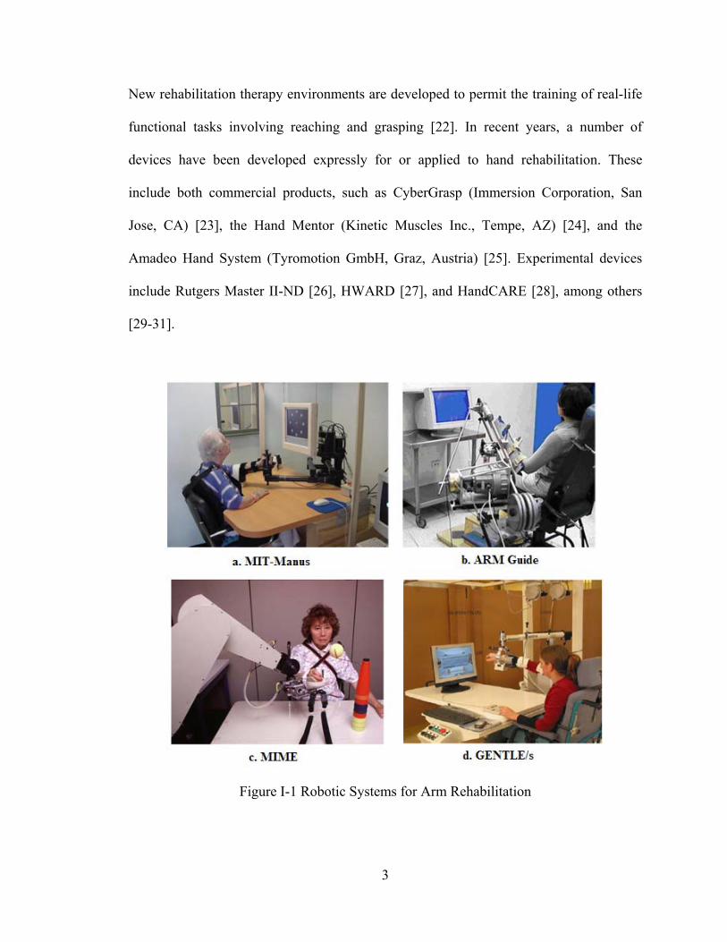
following stroke. The MIT-Manus (Massachusetts Institute of Technology Manus) [11,
12] (Figure I-1.a), Assisted Rehabilitation and Measurement (ARM) Guide [13, 14]
(Figure I-1.b), Mirror Image Movement Enabler (MIME) [15-17] (Figure I-1.c) and
GENTLE/s [18] (Figure I-1.d) are developed to facilitate the arm movement of stroke
patients. Robotic devices designed for wrist rehabilitation have been reported in [19-21].
3
New rehabilitation therapy environments are developed to permit the training of real-life
functional tasks involving reaching and grasping [22]. In recent years, a number of
devices have been developed expressly for or applied to hand rehabilitation. These
include both commercial products, such as CyberGrasp (Immersion Corporation, San
Jose, CA) [23], the Hand Mentor (Kinetic Muscles Inc., Tempe, AZ) [24], and the
Amadeo Hand System (Tyromotion GmbH, Graz, Austria) [25]. Experimental devices
include Rutgers Master II-ND [26], HWARD [27], and HandCARE [28], among others
[29-31].
Figure I-1 Robotic Systems for Arm Rehabilitation
4
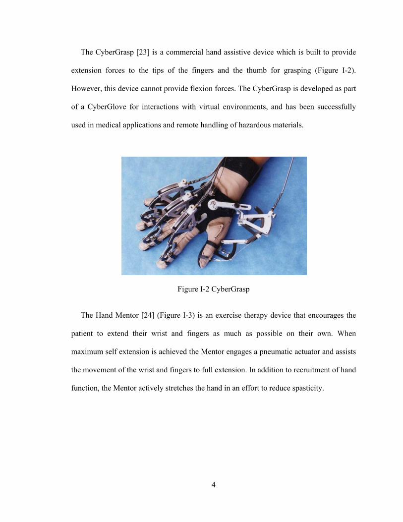
The CyberGrasp [23] is a commercial hand assistive device which is built to provide
extension forces to the tips of the fingers and the thumb for grasping (Figure I-2).
However, this device cannot provide flexion forces. The CyberGrasp is developed as part
of a CyberGlove for interactions with virtual environments, and has been successfully
used in medical applications and remote handling of hazardous materials.
Figure I-2 CyberGrasp
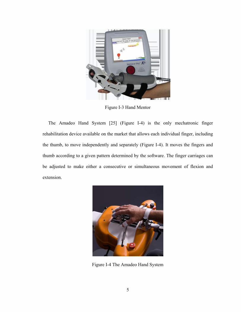
The Hand Mentor [24] (Figure I-3) is an exercise therapy device that encourages the
patient to extend their wrist and fingers as much as possible on their own. When
maximum self extension is achieved the Mentor engages a pneumatic actuator and assists
the movement of the wrist and fingers to full extension. In addition to recruitment of hand
function, the Mentor actively stretches the hand in an effort to reduce spasticity.
5
Figure I-3 Hand Mentor
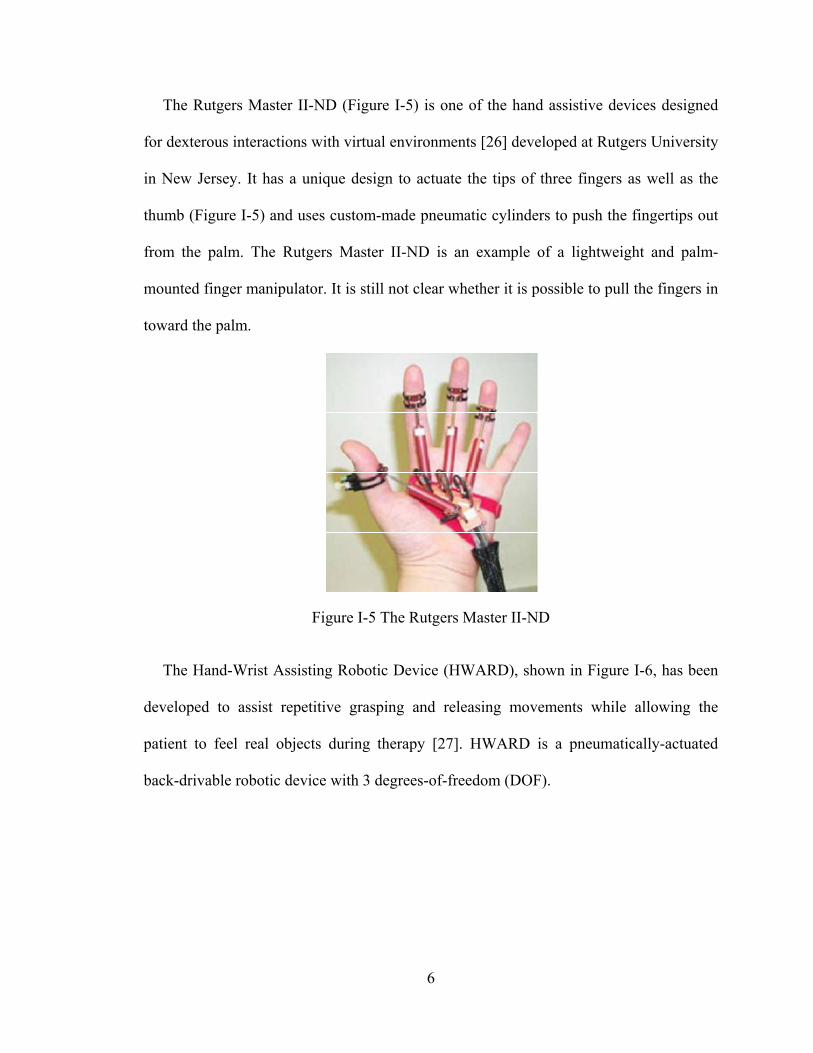
The Amadeo Hand System [25] (Figure I-4) is the only mechatronic finger
rehabilitation device available on the market that allows each individual finger, including
the thumb, to move independently and separately (Figure I-4). It moves the fingers and
thumb according to a given pattern determined by the software. The finger carriages can
be adjusted to make either a consecutive or simultaneous movement of flexion and
extension.
Figure I-4 The Amadeo Hand System
6
The Rutgers Master II-ND (Figure I-5) is one of the hand assistive devices designed
for dexterous interactions with virtual environments [26] developed at Rutgers University
in New Jersey. It has a unique design to actuate the tips of three fingers as well as the
thumb (Figure I-5) and uses custom-made pneumatic cylinders to push the fingertips out
from the palm. The Rutgers Master II-ND is an example of a lightweight and palm-
mounted finger manipulator. It is still not clear whether it is possible to pull the fingers in
toward the palm.
Figure I-5 The Rutgers Master II-ND
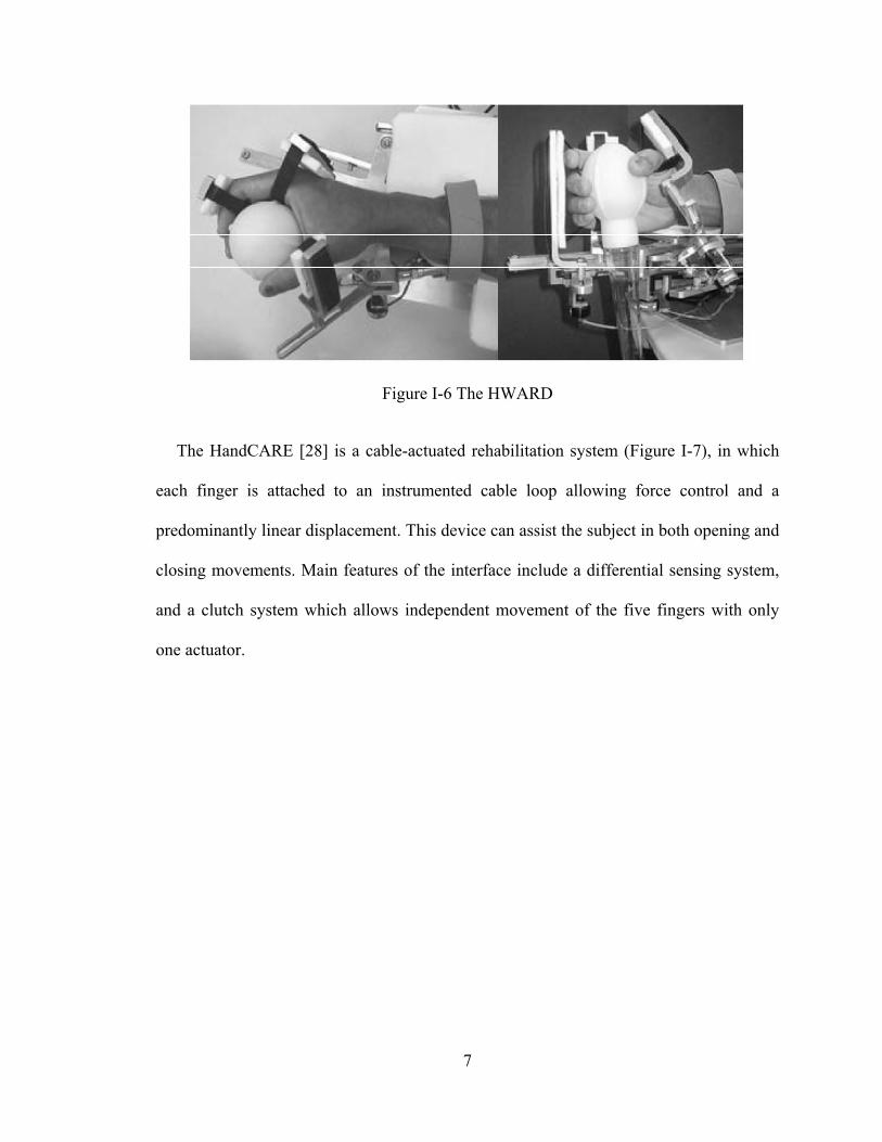
The Hand-Wrist Assisting Robotic Device (HWARD), shown in Figure I-6, has been
developed to assist repetitive grasping and releasing movements while allowing the
patient to feel real objects during therapy [27]. HWARD is a pneumatically-actuated
back-drivable robotic device with 3 degrees-of-freedom (DOF).
7
Figure I-6 The HWARD
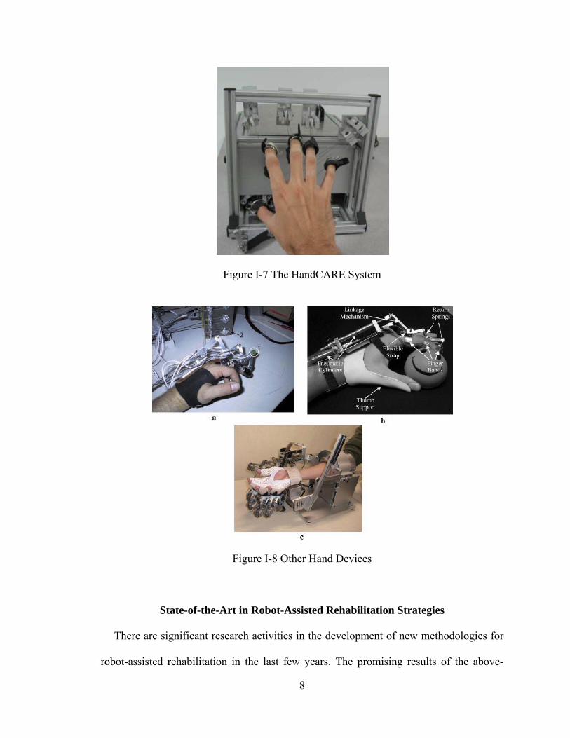
The HandCARE [28] is a cable-actuated rehabilitation system (Figure I-7), in which
each finger is attached to an instrumented cable loop allowing force control and a
predominantly linear displacement. This device can assist the subject in both opening and
closing movements. Main features of the interface include a differential sensing system,
and a clutch system which allows independent movement of the five fingers with only
one actuator.
8
Figure I-7 The HandCARE System
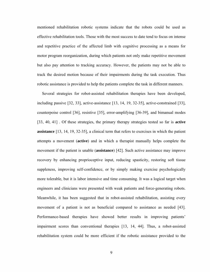
Figure I-8 Other Hand Devices
State-of-the-Art in Robot-Assisted Rehabilitation Strategies
There are significant research activities in the development of new methodologies for
robot-assisted rehabilitation in the last few years. The promising results of the above-
9
mentioned rehabilitation robotic systems indicate that the robots could be used as
effective rehabilitation tools. Those with the most success to date tend to focus on intense
and repetitive practice of the affected limb with cognitive processing as a means for
motor program reorganization, during which patients not only make repetitive movement
but also pay attention to tracking accuracy. However, the patients may not be able to
track the desired motion because of their impairments during the task execution. Thus
robotic assistance is provided to help the patients complete the task in different manners.
Several strategies for robot-assisted rehabilitation therapies have been developed,
including passive [32, 33], active-assistance [13, 14, 19, 32-35], active-constrained [33],
counterpoise control [36], resistive [35], error-amplifying [36-39], and bimanual modes
[33, 40, 41] . Of these strategies, the primary therapy strategies tested so far is active
assistance [13, 14, 19, 32-35], a clinical term that refers to exercises in which the patient
attempts a movement (active) and in which a therapist manually helps complete the
movement if the patient is unable (assistance) [42]. Such active assistance may improve
recovery by enhancing proprioceptive input, reducing spasticity, restoring soft tissue
suppleness, improving self-confidence, or by simply making exercise psychologically
more tolerable, but it is labor intensive and time consuming. It was a logical target when
engineers and clinicians were presented with weak patients and force-generating robots.
Meanwhile, it has been suggested that in robot-assisted rehabilitation, assisting every
movement of a patient is not as beneficial compared to assistance as needed [43].
Performance-based therapies have showed better results in improving patients’
impairment scores than conventional therapies [13, 14, 44]. Thus, a robot-assisted
rehabilitation system could be more efficient if the robotic assistance provided to the
10
patient is given as and when needed based on the performance of the patient, which is
called assist-as-needed training in this manuscript.
Meanwhile, recent research has demonstrated that movement tracking training that
requires cognitive processing achieved greater gains in performance than that of
movement training that did not require cognitive processing [45]. Moreover, recent
research in many models and artificial learning systems such as neural networks suggest
that error drives sensorimotor learning of a person, so that one can learn adaptation more
quickly if the error is augmented to a certain degree [46]. Such error-driven learning
processes are believed to be central to adaptation and the acquisition of skill in human
movement [44, 47]. It has been shown that visual error augmentation can improve the
rate and extent of motor learning in healthy participants [38] and elicit functional
improvements in patients with chronic stroke and traumatic brain injury [39]. Thus, it is
desirable to integrate the visual feedback and visual error augmentation strategy in
rehabilitation training.
Scope and Summary of the Dissertation
The purpose of my research work is to explore how to improve robot-assisted
rehabilitation for upper extremity disability following stroke. We have probed this
question in three different approaches including system enhancement (Manuscript I),
evaluation of novel training strategies (Manuscript II) and design of new hardware
(Manuscript III and IV). The dissertation is organized as follows:
First in Chapter II, development of a robotic system incorporating verbal feedback for
arm rehabilitation is described. This robotic system is able to recognize the participant’s
11
verbal commands and adjust the rehabilitation training online accordingly. A high-level
supervisory controller is designed to monitor the task execution, make task adjustment
according to the recognized verbal feedback from the participant during the task
execution to impart effective therapy to the participant in an automated manner. This
enhancement will keep the patients in the loop and reduce the intervention and workload
of the therapists.
Next in Chapter III, an investigation of a novel rehabilitation strategy in improving the
efficacy of robot-assisted arm rehabilitation is presented. Two rehabilitation training
strategies, assist-as-needed and visual error augmentation, are implemented on the
existing robotic system. A crossover study is designed to assess the impact of the
integrated training method of these two strategies on robot-assisted arm rehabilitation.
The experimental results show that the integrated training method has improved the
rehabilitation training efficacy compared to the assist-as-needed method. This
improvement is statistically significant.
While existing robotic systems may be able to provide the hardware platforms for arm
rehabilitation, the same is not currently true for the hand. There are several technical
challenges, such as designing an articulated system to accommodate the many joints of
the hand and controlling these joints independently, while providing the necessary levels
of power, speed, and reliability. Existing hand devices do not provide the complete range
of speed, force, and independence of joint control to thoroughly explore the space of
different training algorithms and environments [23]-[31].
Thus, in Chapter IV and V, the design of an actuated hand exoskeleton (AHX) is
presented. The AHX, consisting of an actuated finger exoskeleton (AFX) and an actuated
12
thumb exoskeleton (ATX), has the potential to serve as a test-bed to facilitate hand
rehabilitation and motor control study for stroke patients. In Chapter IV, the performance
of a real-time control system for the AFX with both position and torque control is shown.
The AFX exhibited high speed and torque capacity with good backdrivability. Then, in
Chapter V, the design and control of an ATX with 5 active degree-of-freedoms (DOF)
and 3 passive DOF that allows individual actuation of each DOF for the human thumb
are described. The ATX showed independent actuation of each thumb joint with high
speed and torque capacity and good backdrivability.
The proposed research work is presented in 4 manuscripts as follows:
Manuscript 1: Incorporating Verbal Feedback into a Robot-Assisted Rehabilitation
System
Background
In the last few years, robot-assistance for physical rehabilitation of stroke survivors
has been an active area of research [11]-[31]. There are two important roles that a robotic
rehabilitation system needs to fulfill. First, robotic rehabilitation systems need to monitor
the task and safety issues, provide assessment of progress, and alter the task parameters to
impart effective therapy. Second, robotic rehabilitation systems need to alter the
presentation of the rehabilitation therapy task based on patients’ feedback. A robotic
system that is able to monitor the task and safety, recognize the patients’ feedback and
alter the presentation of the rehabilitation therapy in an automated manner will greatly
facilitate robot-assisted rehabilitation.
13
Summary of Contribution
The main contributions of this work are to augment the capabilities of a robotic
rehabilitation system by enabling it to: 1) comprehensively monitor the task and safety
issues, provide assessment of the progress, and alter the task parameters to impart
effective therapy during the execution of the task in an automated manner; and 2)
recognize patient’s verbal feedback such that it can address his/her concern. This work is
built upon the preliminary work [48, 49] on an intelligent control framework for robotic
rehabilitation to incorporate patient feedback within the overall control architecture. My
main contributions to this work are: 1) to establish the real-time communication interface
between the robotic system and voice recognition system, and 2) to develop the high-
level supervisory controller for the robotic system that monitors the task execution and
safety, provides assessment of the progress, alters the rehabilitation therapy according to
the recognized voice feedback of the subjects.
Barkana, D.E.; Wang, F.; Das, J.; Sarkar, N.; Groomes, T.E., "A step toward
increasing automation in robot-assisted rehabilitation," Biomedical Robotics and
Biomechatronics, 2008. BioRob 2008. 2nd IEEE RAS & EMBS International
Conference on, pp.930-935, 19-22 Oct. 2008.
Duygun Erol Barkana, Jadav Das, Furui Wang, Thomas E. Groomes and Nilanjan
Sarkar, “Incorporating verbal feedback into a robot-assisted rehabilitation system”.
Robotica, 2011, vol. 29, issue 3, pp 433-443.
14
Manuscript 2: Impact of Visual Error Augmentation When Integrated with Assist-
as-needed Training Method in Robot-assisted Rehabilitation
Background
Robot-assisted rehabilitation has been an active research topic in recent years [11]-
[31]. Various rehabilitation training strategies have been proposed to improve the
efficacy of robot-assisted rehabilitation training [42]. Two novel strategies, assist-as-
needed and visual error augmentation, have been individually investigated in literatures
and suggested to be beneficial for upper-limb rehabilitation [11, 36]. However, none of
the work has investigated the combination of these two training strategies, which could
be integrated in robot-assisted rehabilitation, with the potential to take the advantages of
both training strategies.
Summary of Contribution
There are two contributions in this work. The first contribution is to enhance the
functionality of the existing robotic system for arm rehabilitation with the assist-as-
needed and visual error augmentation training method, and design a controller that could
execute the two training methods in an integrated manner. The second contribution is to
design a crossover study to investigate the assist-as-needed only and the integrated
training methods, and to conduct statistical analysis to compare the training efficiency of
these two methods. The experimental results show that: 1) the robotic system is able to
provide the designed training methods; and 2) the integrated training method shows
improved training efficiency compared to the assist-as-needed only training method.
15
Furui Wang; Barkana, D.E.; Sarkar, N., "Impact of Visual Error Augmentation
When Integrated With Assist-as-Needed Training Method in Robot-Assisted
Rehabilitation," Neural Systems and Rehabilitation Engineering, IEEE Transactions
on , vol.18, no.5, pp.571-579, Oct. 2010.
Furui Wang; Barkana, D.E.; Sarkar, N., "Integration of error augmentation training
method to an assistive controller for rehabilitation robotic systems," Rehabilitation
Robotics, 2009. ICORR 2009. IEEE International Conference on, pp.463-468, 23-
26 June 2009.
Furui Wang; Barkana, D.E.; Sarkar, N., "Evaluation of a robot-assisted
rehabilitation system with assist-as- needed and visual error augmentation training
methods," Intelligent Robots and Systems, 2009. IROS 2009. IEEE/RSJ
International Conference on, pp.3555-3560, 10-15 Oct. 2009.
Manuscript 3: Design and Development of an Actuated Finger Exoskeleton for
Hand Rehabilitation following Stroke
Background
Finger impairment following stroke results in significant deficits in hand manipulation
and the performance of everyday tasks. Recent advances in rehabilitation robotics have
shown improvement in efficacy of rehabilitation [50], [51]. Current devices [23]-[31],
however, lack the capacity to accurately interface with the human finger at levels of
velocity and torque comparable to the performance of everyday hand manipulation tasks.

16
Summary of Contribution
The main contributions of this work are the design and control of the Actuated Finger
Exoskeleton (AFX), a three DOF robotic exoskeleton for the index finger. The AFX
improves on current rehabilitation robotics solutions by providing a versatile framework
with high performance, real-time control, and forces and speeds comparable to normal
human function. The AFX will allow for normal task execution in a rehabilitation or
motor study environment. My main contributions to this work are to analyze the
kinematics of the AFX model and to develop and implement the position and torque
control system in real-time.
Jones, C.L.; Furui Wang; Robert Morrison; Sarkar, N.; Kamper, D.G., "Design and
development of an Actuated Finger Exoskeleton for hand rehabilitation following
stroke,", submitted to IEEE/ASME Transaction on Mechatronics.
Jones, C.L.; Furui Wang; Osswald, C.; Xuan Kang; Sarkar, N.; Kamper, D.G.,
"Control and kinematic performance analysis of an Actuated Finger Exoskeleton for
hand rehabilitation following stroke," Biomedical Robotics and Biomechatronics
(BioRob), 2010 3rd IEEE RAS and EMBS International Conference on, pp.282-287,
26-29 Sept. 2010.
Manuscript 4: Design and Development of an Actuated Thumb Exoskeleton for
Hand Rehabilitation following Stroke
Background
Hand impairment is a prevalent outcome for a variety of neuromuscular disorders,
such as stroke. Loss of hand function due to neuromuscular disorders frequently prevents
17
effective self-care and limits employment opportunities. A number of devices have been
developed expressly for or applied to hand rehabilitation [23]-[31]. As such, they
typically do not allow for independent control of the joints, especially for the thumb with
five degrees-of-freedom (DOF). Others may insufficient torque or overly restrict thumb
movement. Thus, these devices are not suitable to serve as a test-bed for studying the
thumb motor control and thumb rehabilitation.
Summary of Contribution
The main contributions of this work are to design and develop an actuated thumb
exoskeleton (ATX), with five active DOF and 3 passive DOF, which allows independent
actuation of each DOF of the thumb. The ATX is able to provide individual actuation for
each thumb DOF, while possessing sufficient torque to overcome possibly excessive
coactivation and increased stiffness in the affected thumb and high speed joint motion
comparable to the natural motion of the human thumb joints. This ATX has the potential
to serve as a test bed to evaluate thumb rehabilitation therapies and motor learning
paradigms. My contributions in this work are the mechanical design, kinematics analysis,
actuation and sensory systems development, instrumentation and real-time control system
design and implementation.
Wang, Furui; Shastri, Milind; Jones, Christopher L.; Kamper, Derek G.; Sarkar,
Nilanjan, "Design and control of an actuated thumb exoskeleton for hand
rehabilitation following stroke," Robotics and Automation (ICRA), 2011 IEEE
International Conference on , pp.3688-3693, 9-13 May 2011.
18
Wang F, Jones C, Shastri M, Gupta V, Osswald C, Kang X, Kamper D, Sarkar N,
“Design and development of an actuated thumb exoskeleton for hand rehabilitation
following stroke,” in preparation for submission to IEEE/ASME Transaction on
Mechatronics.
References
[1] American Heart Association, Heart and Stroke Statistical Update, 2010. Available: http://www.Americanheart.org/statistics/stroke.htm
[2] R Bonita, A Stewart, et al., "International trends in stroke mortality: 1970-1985.," Stroke, vol. 21, pp. 989-92, Jul 1990.
[3] JP Broderick, SJ Phillips, et al., "Incidence rates of stroke in the eighties: the end of the decline in stroke?," Stroke, vol. 20, pp. 577-82, May 1989.
[4] CS Gray, JM French, et al., "Motor recovery following acute stroke.," Age Ageing, vol. 19, pp. 179-84, May 1990.
[5] H Nakayama, HS Jørgensen, et al., "Recovery of upper extremity function in stroke patients: the Copenhagen Stroke Study.," Arch Phys Med Rehabil, vol. 75, pp. 394-8, Apr 1994.
[6] VM Parker, DT Wade, et al., "Loss of arm function after stroke: measurement, frequency, and recovery.," Int Rehabil Med, vol. 8, pp. 69-73, 1986.
[7] CA Trombly, MV Radomski, et al., "Stroke," in Occupational therapy for physical dysfunction, ed: Williams & Wilkins Baltimore, MD, 1989.
[8] E Taub, NE Miller, et al., "Technique to improve chronic motor deficit after stroke.," Arch Phys Med Rehabil, vol. 74, pp. 347-54, Apr 1993.
[9] BT Volpe, ""Stroke, stroke": a coxswain's call for more work and more innovation.," J Rehabil Res Dev, vol. 41, pp. vii-x, May 2004.
[10] E Taub, G Uswatte, et al., "Constraint-Induced Movement Therapy: a new family of techniques with broad application to physical rehabilitation--a clinical review.," J Rehabil Res Dev, vol. 36, pp. 237-51, Jul 1999.
[11] H. I. Krebs, J. J. Palazzolo, et al., "Rehabilitation Robotics: Performance-Based Progressive Robot-Assisted Therapy," Autonomous Robots, vol. 15, pp. 7-20, 2003.
19
[12] HI Krebs, M Ferraro, et al., "Rehabilitation robotics: pilot trial of a spatial extension for MIT-Manus.," J Neuroeng Rehabil, vol. 1, p. 5, Oct 2004.
[13] LE Kahn, ML Zygman, et al., "Robot-assisted reaching exercise promotes arm movement recovery in chronic hemiparetic stroke: a randomized controlled pilot study.," J Neuroeng Rehabil, vol. 3, p. 12, 2006.
[14] LE Kahn, PS Lum, et al., "Robot-assisted movement training for the stroke-impaired arm: Does it matter what the robot does?," J Rehabil Res Dev, vol. 43, pp. 619-30, 2006 Aug-Sep 2006.
[15] PS Lum, CG Burgar, et al., "Quantification of force abnormalities during passive and active-assisted upper-limb reaching movements in post-stroke hemiparesis.," IEEE Trans Biomed Eng, vol. 46, pp. 652-62, Jun 1999.
[16] CG Burgar, PS Lum, et al., "Development of robots for rehabilitation therapy: the Palo Alto VA/Stanford experience.," J Rehabil Res Dev, vol. 37, pp. 663-73, 2000 Nov-Dec 2000.
[17] PS Lum, CG Burgar, et al., "MIME robotic device for upper-limb neurorehabilitation in subacute stroke subjects: A follow-up study.," J Rehabil Res Dev, vol. 43, pp. 631-42, 2006 Aug-Sep 2006.
[18] Rui Loureiro, Farshid Amirabdollahian, et al., "Upper Limb Robot Mediated Stroke Therapyâ ”GENTLE/s Approach," Autonomous Robots, vol. 15, pp. 35-
51, 2003.
[19] S Hesse, G Schulte-Tigges, et al., "Robot-assisted arm trainer for the passive and active practice of bilateral forearm and wrist movements in hemiparetic subjects.," Arch Phys Med Rehabil, vol. 84, pp. 915-20, Jun 2003.
[20] S. K. Charles, H. I. Krebs, et al., "Wrist rehabilitation following stroke: initial clinical results," in Rehabilitation Robotics, 2005. ICORR 2005. 9th International Conference on, 2005, pp. 13-16.
[21] Abhishek Gupta, Marcia K. O'Malley, et al., "Design, Control and Performance of RiceWrist: A Force Feedback Wrist Exoskeleton for Rehabilitation and Training," The International Journal of Robotics Research, vol. 27, pp. 233-251, February 1, 2008 2008.
[22] M. J. Johnson, K. J. Wisneski, et al., "Development of ADLER: The Activities of Daily Living Exercise Robot," in Biomedical Robotics and Biomechatronics, 2006. BioRob 2006. The First IEEE/RAS-EMBS International Conference on, 2006, pp. 881-886.
[23] SV Adamovich, GG Fluet, et al., "Design of a complex virtual reality simulation to train finger motion for persons with hemiparesis: a proof of concept study.," J Neuroeng Rehabil, vol. 6, p. 28, 2009.
20
[24] Kinetic Muscles Inc., Hand Mentor. Available: http://www.kineticmuscles.com/index.html
[25] Tyromotion GmbH, Amadeo Hand System. Available: http://www.tyromotion.com/en/products/amadeo/
[26] D Jack, R Boian, et al., "Virtual reality-enhanced stroke rehabilitation," IEEE Transactions on Neural Systems and Rehabilitation Engineering, vol. 9, pp. 308-318, 2001.
[27] CD Takahashi, L Der-Yeghiaian, et al., "Robot-based hand motor therapy after stroke.," Brain, vol. 131, pp. 425-37, Feb 2008.
[28] L Dovat, O Lambercy, et al., "HandCARE: a cable-actuated rehabilitation system to train hand function after stroke.," IEEE Trans Neural Syst Rehabil Eng, vol. 16, pp. 582-91, Dec 2008.
[29] A. Wege and G. Hommel, "Development and control of a hand exoskeleton for rehabilitation of hand injuries," in Intelligent Robots and Systems, 2005. (IROS 2005). 2005 IEEE/RSJ International Conference on, 2005, pp. 3046-3051.
[30] M. DiCicco, L. Lucas, et al., "Comparison of control strategies for an EMG controlled orthotic exoskeleton for the hand," in Robotics and Automation, 2004. Proceedings. ICRA '04. 2004 IEEE International Conference on, 2004, pp. 1622-1627 Vol.2.
[31] H. Kawasaki, S. Ito, et al., "Development of a Hand Motion Assist Robot for Rehabilitation Therapy by Patient Self-Motion Control," in Rehabilitation Robotics, 2007. ICORR 2007. IEEE 10th International Conference on, 2007, pp. 234-240.
[32] BT Volpe, HI Krebs, et al., "A novel approach to stroke rehabilitation: robot-aided sensorimotor stimulation.," Neurology, vol. 54, pp. 1938-44, May 2000.
[33] PS Lum, CG Burgar, et al., "Robot-assisted movement training compared with conventional therapy techniques for the rehabilitation of upper-limb motor function after stroke.," Arch Phys Med Rehabil, vol. 83, pp. 952-9, Jul 2002.
[34] L. E. Kahn, M. L. Zygman, et al., "Effect of robot-assisted and unassisted exercise on functional reaching in chronic hemiparesis," in Engineering in Medicine and Biology Society, 2001. Proceedings of the 23rd Annual International Conference of the IEEE, 2001, pp. 1344-1347 vol.2.
[35] SE Fasoli, HI Krebs, et al., "Effects of robotic therapy on motor impairment and recovery in chronic stroke.," Arch Phys Med Rehabil, vol. 84, pp. 477-82, Apr 2003.
[36] J. L. Patton, F. A. Mussa-Ivaldi, et al., "Altering movement patterns in healthy and brain-injured subjects via custom designed robotic forces," in Engineering in
21
Medicine and Biology Society, 2001. Proceedings of the 23rd Annual International Conference of the IEEE, 2001, pp. 1356-1359 vol.2.
[37] B. R. Brewer, R. Klatzky, et al., "Effects of visual feedback distortion for the elderly and the motor-impaired in a robotic rehabilitation environment," in Robotics and Automation, 2004. Proceedings. ICRA '04. 2004 IEEE International Conference on, 2004, pp. 2080-2085 Vol.2.
[38] Yejun Wei, P. Bajaj, et al., "Visual error augmentation for enhancing motor learning and rehabilitative relearning," in Rehabilitation Robotics, 2005. ICORR 2005. 9th International Conference on, 2005, pp. 505-510.
[39] BR Brewer, R Klatzky, et al., "Visual feedback distortion in a robotic environment for hand rehabilitation.," Brain Res Bull, vol. 75, pp. 804-13, Apr 2008.
[40] S. P. Lum, S. L. Lehman, et al., "The bimanual lifting rehabilitator: an adaptive machine for therapy of stroke patients," Rehabilitation Engineering, IEEE Transactions on, vol. 3, pp. 166-174, 1995.
[41] P. S. Lum, D. J. Reinkensmeyer, et al., "Robotic assist devices for bimanual physical therapy: preliminary experiments," Rehabilitation Engineering, IEEE Transactions on, vol. 1, pp. 185-191, 1993.
[42] DJ Reinkensmeyer, JL Emken, et al., "Robotics, motor learning, and neurologic recovery.," Annu Rev Biomed Eng, vol. 6, pp. 497-525, 2004.
[43] D. J. Reinkensmeyer, "How to retrain movement after neurologic injury: a computational rationale for incorporating robot (or therapist) assistance," in Engineering in Medicine and Biology Society, 2003. Proceedings of the 25th Annual International Conference of the IEEE, 2003, pp. 1479-1482 Vol.2.
[44] M Kawato, "The feedback-error-learning neural network for supervised motor learning," in Advanced neural computers, R. Eckmiller, Ed., ed: North Holland, 1990, pp. 365-372.
[45] JR Carey, E Bhatt, et al., "Neuroplasticity promoted by task complexity.," Exerc Sport Sci Rev, vol. 33, pp. 24-31, Jan 2005.
[46] David E. Rumelhart, Geoffrey E. Hinton, et al., "Learning representations by back-propagating errors," Nature, vol. 323, pp. 533-536, 1986.
[47] DM Wolpert, Z Ghahramani, et al., "An internal model for sensorimotor integration.," Science, vol. 269, pp. 1880-2, Sep 1995.
[48] D. Erol and N. Sarkar, "Intelligent control for robotic rehabilitation after stroke," Journal of Intelligent & Robotic Systems, vol. 50, pp. 341-360, Dec 2007.
22
[49] D. Erol and N. Sarkar, "Coordinated control of assistive robotic devices for activities of daily living tasks," IEEE Transactions on Neural Systems and Rehabilitation Engineering, vol. 16, pp. 278-285, Jun 2008.
[50] S. L. Wolf, S. Blanton, et al., "Repetitive task practice: A critical review of constraint-induced movement therapy in stroke," Neurologist, vol. 8, pp. 325-338, Nov 2002.
[51] C. J. Winstein, D. K. Rose, et al., "A randomized controlled comparison of upper-extremity rehabilitation strategies in acute stroke: A pilot study of immediate and long-term outcomes," Archives of Physical Medicine and Rehabilitation, vol. 85, pp. 620-628, Apr 2004.
23
CHAPTER II
MANUSCRIPT I: INCORPORATING VERBAL FEEDBACK INTO A ROBOT-
ASSISTED REHABILITATION SYSTEM
Duygun Erol Barkana, Furui Wang, Jadav Das, Nilanjan Sarkar and Thomas Groomes
(This work has been published in Robotica, vol.29, no.3, pp.433-443, 2011, and
partially published in the IEEE International Conference on Biomedical Robotics and
Biomechatronics, BioRob 2008.)
24
Abstract
This paper presents a control architecture, which has the potential to monitor the task,
safety issues, to provide assessment of the progress and alter the task parameters, and to
incorporate patient’s feedback in order to make the necessary modifications to impart
effective therapy during the execution of the task in an automated manner. Experimental
results are presented to demonstrate the efficacy of the proposed control architecture.
Keywords – rehabilitation system, human intention recognition system, hybrid systems
Introduction
Stroke is a highly prevalent condition especially among the elderly that results in high
costs to the individual and society [1]. In the last few years, robot-assisted rehabilitation
for physical rehabilitation of the stroke patients has been an active research area to assist,
monitor, and quantify rehabilitation therapies [4]-[11]. Robot-assisted rehabilitation has
shown to provide repetitive movement exercise and standardized delivery of therapy with
the potential of enhancing quantification of the therapeutic process for stroke patients [4]-
[11]. Studies in this field suggest that robot-assisted rehabilitation results in improved
performance of functional tasks.
There are two important issues that a robotic rehabilitation system needs to address.
First, robotic rehabilitation systems need to comprehensively monitor the task and safety
issues, provide assessment of the progress, and alter the task parameters to impart
effective therapy. Generally, a therapist administers the therapy where he/she monitors
the progress of the tasks as well as patient’s safety, and assesses whether the task needs to
be updated based on the need of individual patient. As a result, a robotic system will
25
likely reduce the amount of time of the therapist as well as decrease his/her workload,
and consequently, decrease the cost of treatment. MIT-MANUS [4], MIME [5] and
GENTLE/s [6] were among the first rehabilitation robotic systems to implement safety.
Second, robotic rehabilitation systems need to alter the presentation of the rehabilitation
therapy task based on patients’ feedback. Altering the presentation of the rehabilitation
therapy is an important issue since patients or therapists should be able to express how
they feel about the task, and necessary modifications need to be performed about the
therapy. Recently developed rehabilitation devices like ARMin [7], ADLER [8], T-
WREX [9], HenRiE [10] and HARMiS [11] provide assistance to the patients as needed
based on the patients’ position, velocity and force feedback. However, this feedback only
provides information about patient’s motion capabilities, and it does not directly
represent the feelings of the patient or the therapist about the task execution. For example,
if the patient does not feel comfortable in moving his/her arm at a specified speed, then
the therapist or the robot-assisted system may need to change the task execution to slow
down. Note that, when a therapist manually administers rehabilitation therapy, he/she
keeps the patient in the loop and adjusts the therapy. Therefore, it is important for a
robot-assisted rehabilitation system to alter the presentation of the rehabilitation therapy
task automatically considering patients and therapists feedback. To our knowledge none
of the existing robot-assisted rehabilitation systems use feedback of both patient’s and
therapist’s to modify the presentation of the task. Spoken words of stroke patients or
therapists can be one of the available options to incorporate their verbal feedback into the
robot-assisted rehabilitation system so that the necessary modifications on the robot-
assisted rehabilitation can be made immediately.
26
In this work, we attempt to address how to augment the capabilities of a robotic
rehabilitation system by enabling it to: 1) comprehensively monitor the task and safety
issues, provide assessment of the progress, and alter the task parameters to impart
effective therapy during the execution of the task in an automated manner; and 2)
recognize patient’s verbal feedback such that it can address his/her concerns. This work
is built upon our preliminary work on an intelligent control framework for robotic
rehabilitation [12]-[16] to incorporate patient’s feedback within the overall control
architecture. The paper is organized into the following sections. It first presents the
intelligent control architecture in Section II. A rehabilitation robotic system, a human
intention recognition system, and one of the rehabilitation tasks that are used to
demonstrate the versatility of the presented control architecture are presented in Section
III. Results of the experiments are presented in Section IV to demonstrate the efficacy of
the control architecture. Section V discusses potential contributions of this work and
possible directions for future work.
Control Architecture
Let us first present the proposed framework in the context of one of the rehabilitation
tasks, called the reaching task. The reaching task designed in this work requires a
combination of shoulder and elbow movements, which could increase the active range of
motion (AROM) in the shoulder and the elbow in preparation for later functional
reaching activities in rehabilitation. In this task, the participants are asked to move their
arms in the forward direction to reach a desired point in space and then bring it back to
the starting position repeatedly within a specified time.
27
Stroke survivors, in general, may not be able to track the desired motion trajectory in
this reaching task because of their motor impairment. A low-level assistive controller will
be used to provide robotic assistance to a patient’s arm movement as and when needed to
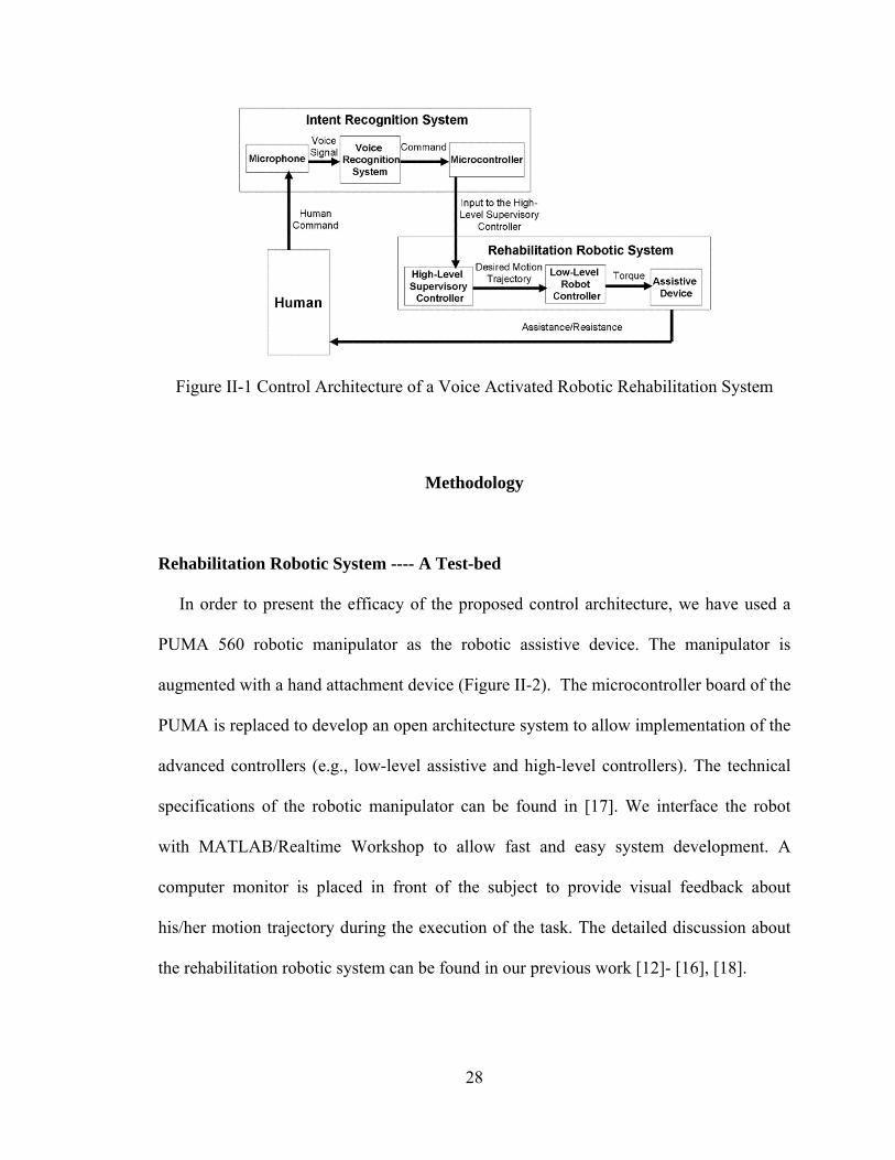
help him/her to complete the reaching task. In this architecture, an intention recognition
system recognizes the patient’s spoken words (e.g., fast, slow, continue and stop) using a
microphone and a voice-recognition technique and then converts the spoken words into
control commands (Figure II-1). The control commands, which represent his/her
intention during the task execution, are sent to the high-level supervisory controller. Once
the high-level supervisory controller receives the commands, the decision-making
module of the high-level supervisory controller generates sequences of control actions
using its decision rules. Additionally, the high-level supervisory controller monitors the
safety events during the execution of the reaching task to decide the necessary
modifications of the task. The high-level supervisory controller presented in this work
ideally plays the role of a human supervisor (therapist) who would otherwise monitor the
patient’s verbal feedback and safety and then assess whether the task needs to be updated.
The high-level supervisory controller is designed considering the requirements of the
therapy, and it can be easily modified and extended for new task requirements. The
decision of the high-level supervisory controller is sent to the low-level assistive
controller to update the task. The updated task is then executed by the low-level assistive
controller. This cycle continues to complete the therapy.
28
Figure II-1 Control Architecture of a Voice Activated Robotic Rehabilitation System
Methodology
Rehabilitation Robotic System ---- A Test-bed
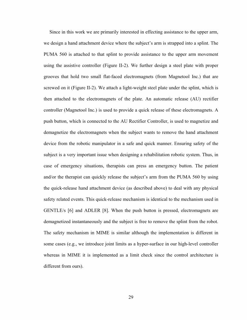
In order to present the efficacy of the proposed control architecture, we have used a
PUMA 560 robotic manipulator as the robotic assistive device. The manipulator is
augmented with a hand attachment device (Figure II-2). The microcontroller board of the
PUMA is replaced to develop an open architecture system to allow implementation of the
advanced controllers (e.g., low-level assistive and high-level controllers). The technical
specifications of the robotic manipulator can be found in [17]. We interface the robot
with MATLAB/Realtime Workshop to allow fast and easy system development. A
computer monitor is placed in front of the subject to provide visual feedback about
his/her motion trajectory during the execution of the task. The detailed discussion about
the rehabilitation robotic system can be found in our previous work [12]- [16], [18].
29
Since in this work we are primarily interested in effecting assistance to the upper arm,
we design a hand attachment device where the subject’s arm is strapped into a splint. The
PUMA 560 is attached to that splint to provide assistance to the upper arm movement
using the assistive controller (Figure II-2). We further design a steel plate with proper
grooves that hold two small flat-faced electromagnets (from Magnetool Inc.) that are
screwed on it (Figure II-2). We attach a light-weight steel plate under the splint, which is
then attached to the electromagnets of the plate. An automatic release (AU) rectifier
controller (Magnetool Inc.) is used to provide a quick release of these electromagnets. A
push button, which is connected to the AU Rectifier Controller, is used to magnetize and
demagnetize the electromagnets when the subject wants to remove the hand attachment
device from the robotic manipulator in a safe and quick manner. Ensuring safety of the
subject is a very important issue when designing a rehabilitation robotic system. Thus, in
case of emergency situations, therapists can press an emergency button. The patient
and/or the therapist can quickly release the subject’s arm from the PUMA 560 by using
the quick-release hand attachment device (as described above) to deal with any physical
safety related events. This quick-release mechanism is identical to the mechanism used in
GENTLE/s [6] and ADLER [8]. When the push button is pressed, electromagnets are
demagnetized instantaneously and the subject is free to remove the splint from the robot.
The safety mechanism in MIME is similar although the implementation is different in
some cases (e.g., we introduce joint limits as a hyper-surface in our high-level controller
whereas in MIME it is implemented as a limit check since the control architecture is
different from ours).
30
Figure II-2 Subject Arm attached to Robot
In this work, a proportional-integral-derivative (PID) position control is used as a low-
level arm assistive controller for providing robotic assistance to a subject to complete the
movement task. The subject receives visual feedback of both their actual position and the
desired position trajectories on a computer screen, which is placed in front of them. Then
the subject is asked to pay attention to tracking the desired position trajectory as
accurately as possible, which keeps them focused on the task. If the subject deviates from
the desired motion, then low-level assistive controller provides robotic assistance to
complement the subject’s effort to complete the task as required.
Human Intention Recognition System
Stroke patients may have difficulties to complete the rehabilitation tasks because of
their limited upper extremity movements. It is important to include patient’s feedback
31
into the robot-assisted rehabilitation system so that it can immediately make the
necessary modifications without therapist’s intervention. Recognizing stroke patients’
spoken words may be one of the available options to incorporate their feedback into the
robot-assisted system.
Various speech recognition techniques have been developed over the years such as a
grammar builder from the Microsoft Speech SDK 5.1 [19], fuzzy command interpreter
[20], Adaptive Input Neural Network (AINN) [21], [22]. MICROEAR (voice activated
hardware) is developed in [23] to recognize a word and then it returns a string which is
then converted to a numerical code. Later, the code is compared with the listed words and
sets the respective flags. Then the relevant functions form the character strings to be
passed on to the robot controller to activate the robot motors using ASCII string. Hidden
Markov Model (HMM) based automatic speech recognizers are developed to recognize
the human voice in [24]. The spoken word from the human is translated in the form of a
quantified desired action for a robot system. New concepts of fuzzy coach-player system
and sub-coach to control robots with natural language commands are presented in [25]. A
probabilistic neural network based learning method is used to acquire the knowledge
from such commands and then implemented in a Mitsubishi PA-10 redundant
manipulator.
In our target application domain, we want to incorporate feedback from stroke patients.
It is likely that many of the stroke patients may not have sufficient control over their
articulatory muscles to communicate long and clear sentences. Moreover, the range of
distortion of spoken words could be an issue in stroke patients. Considering these issues,
we choose to develop a speech recognition system that is capable of robustly identifying
32
a few short phrases or words that have relevance with respect to the rehabilitation therapy.
We use a well-known voice recognition method, called Mel-frequency cepstral
coefficients (MFCCs) in this work [26], [27].
In this work, however, we have used a deterministic approach to speech recognition.
Since in this application we have restricted the number of spoken words and since we
have employed an individual-specific approach, such a deterministic approach is
preferred to a more versatile learning approach. The subject informs his/her intention
using simple words such as "fast", "slow", "stop" and "continue" during the rehabilitation
task. However, these words can not be used directly as commands for the high-level
controller in the control architecture. Initially, each subject is asked to speak each of the
selected words three times. The signal is acquired using the Data acquisition toolbox of
MATLAB R2007a [28] with 8 KHz sampling frequency. An arithmetic average is
computed from these three samples of the same word to account for within person
variation of spoken words. The resultant sample is normalized and broken down into a
series of frames each of which contains 256 data points. We compute 12 mel-frequency
cepstral coefficients (MFCCs) for each frame. The frames and their MFCCs for each
word for each person are stored in a set of 2-dimensional arrays as reference. During the
execution of the rehabilitation task, as the subject speaks any of the selected words, the
start and end points of the sampled speech signal are detected and only the speech portion
of the signal is sent to the feature extraction module. The end point determination concept
used here is originally proposed in [29] based on two features: short-term root-mean-
square-energy and zero crossing rate measures of the signal. The feature extraction
module receives the speech portion of the signal and computes the same 12 MFCCs of
33
the speech by splitting it into frames of 256 samples. The MFCCs are then sent to the
pattern matching module to compare the MFCCs of the spoken word with those of the
reference MFCCs of all the stored words and finds the best match using the least
Euclidean distance measure among the MFCCs between the spoken word and the
reference words. Then the pattern matching module generates a command signal for the
high-level controller. In order for the high-level controller to receive the generated
command, the command is initially sent to the microcontroller (Adapt 9S12D -
Technological Arts Company). The microcontroller transmits the command signal to the
computer of the robotic rehabilitation system through a RS232 serial port. The command
is used by the high-level controller to decide the next plan of action during the execution
of the rehabilitation task.
Modeling of a Rehabilitation Task using Hybrid System Modeling Technique
The proposed control architecture, as described in a previous section, consists of a
low-level arm assistive controller that is used to provide assistance to the subject’s arm
movement and a high-level supervisory controller to monitor the task and the patient’s
safety and to detect the patient’s verbal feedback (intention) in order to make the
necessary modifications to the task. In this work, we use hybrid system modeling
technique to design the proposed control architecture. A hybrid system model has three
parts, a “Plant”, a “Controller” (supervisor) and an Interface [19], [30], [31] (Figure II-3).
A similar hybrid system model has previously designed for same rehabilitation system
and the details can be found in [12]-[16]. First we present the theory of the hybrid control
34
systems. Then the design details of the hybrid control system used for one of the
rehabilitation tasks, a reaching task, is given.
The hybrid control systems consist of a plant which is generally a continuous system
to be controlled by a discrete event controller (DES) connected to the plant via an
interface in a feedback configuration [30], [31]. If the plant is taken together with the
interface, then it is called a DES plant model. The DES controller, which is called the
high-level supervisory controller in this work, controls the DES plant. Let us first present
the DES plant and then describe the DES controller (high-level supervisory controller).
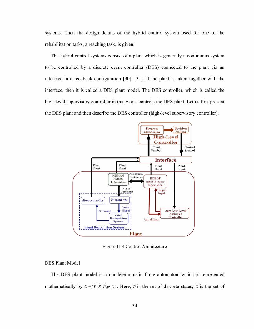
Figure II-3 Control Architecture
DES Plant Model
The DES plant model is a nondeterministic finite automaton, which is represented
mathematically by ),,R~
,X~
,P~
(G . Here, P~ is the set of discrete states; X
~ is the set of
35
plant symbols generated based on the events; and R~ is the set of control symbols
generated by the high-level supervisory controller. P~
R~
P~
: 2 is the state transition
function. The output function, x~P~
P~
: 2 , maps the previous and current plant states to
a set of plant symbols. The set of DES plant model states P~ is based upon the set of
hypersurfaces that separates different discrete states.
The hypersurfaces defined in this work can be classified into two classes: i) the
hypersurfaces describing subject’s capability to complete the task; ii) the hypersurfaces
describing the capability of the rehabilitation robotic system in order to ensure the
execution of the rehabilitation task in a safe manner. The hypersurfaces are defined as
follows: ,h,eh,vvh,vvh itlimlowhigh 4321 here, v is the actual speed of the
robotic device, lowv and highv are the lower and upper limits of the subject’s desired speed
range. e is binary variable representing the subject’s intention to stop or continue the task.
is the actual robotic device configuration vector and itlim is the limit vector of the
configurations. 1h detects if the current task is too fast for the subject and he/she may
want to decrease the speed; 2h detects if the current task is too slow for the subject and
he/she may want to increase the speed; 3h detects whether the subject wants to continue or
to stop the task; 4h detects whether the robotic system configurations, joint angles, torque
etc. are working in safe range.
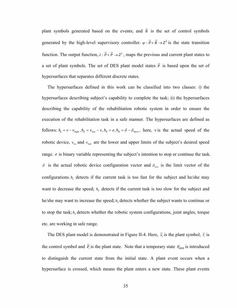
The DES plant model is demonstrated in Figure II-4. Here, ix~ is the plant symbol, ir~ is
the control symbol and iP~ is the plant state. Note that a temporary state 'P0000 is introduced
to distinguish the current state from the initial state. A plant event occurs when a
hypersurface is crossed, which means the plant enters a new state. These plant events
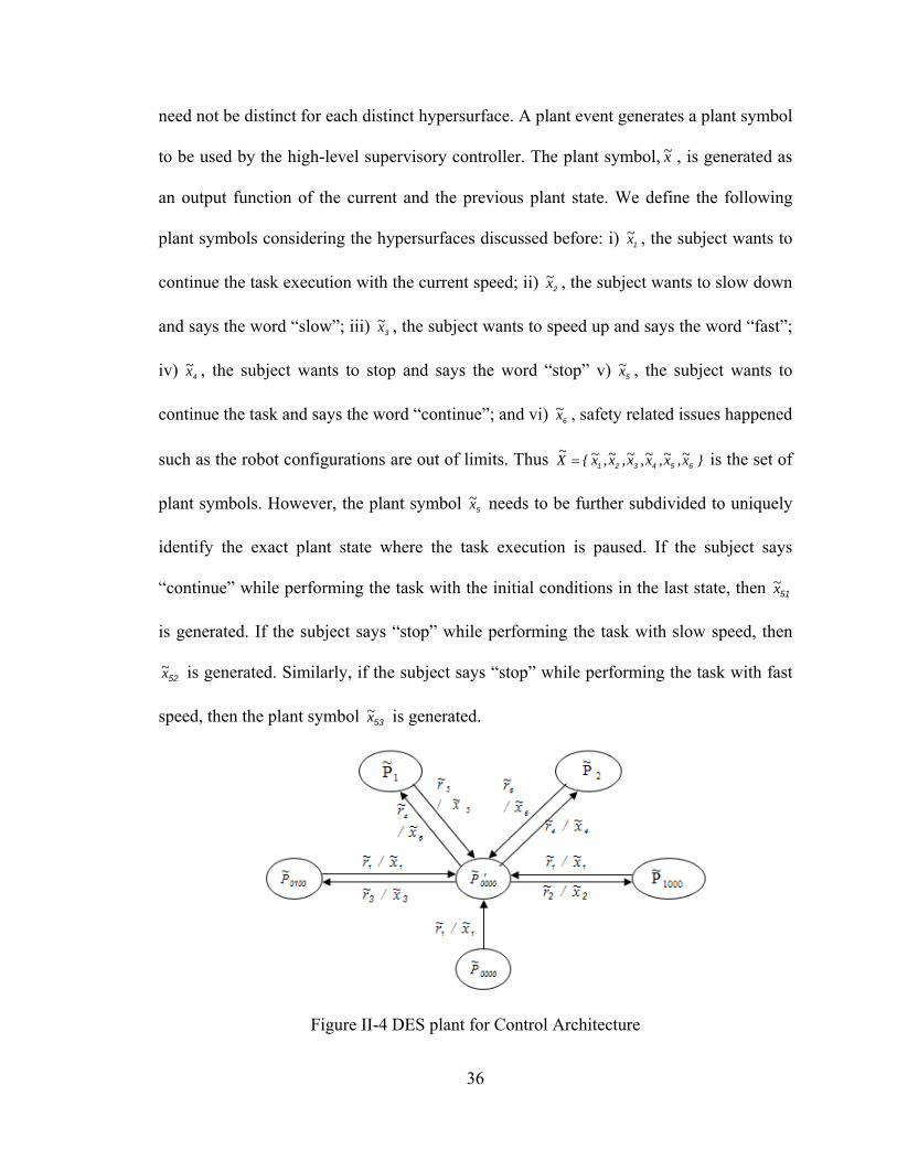
36
need not be distinct for each distinct hypersurface. A plant event generates a plant symbol
to be used by the high-level supervisory controller. The plant symbol, x~ , is generated as
an output function of the current and the previous plant state. We define the following
plant symbols considering the hypersurfaces discussed before: i) 1x~ , the subject wants to
continue the task execution with the current speed; ii) 2x~ , the subject wants to slow down
and says the word “slow”; iii) 3x~ , the subject wants to speed up and says the word “fast”;
iv) 4x~ , the subject wants to stop and says the word “stop” v) 5x~ , the subject wants to
continue the task and says the word “continue”; and vi) 6x~ , safety related issues happened
such as the robot configurations are out of limits. Thus }x~,x~,x~,x~,x~,x~{X~
654321 is the set of
plant symbols. However, the plant symbol 5x~ needs to be further subdivided to uniquely
identify the exact plant state where the task execution is paused. If the subject says
“continue” while performing the task with the initial conditions in the last state, then 51x~
is generated. If the subject says “stop” while performing the task with slow speed, then
52x~ is generated. Similarly, if the subject says “stop” while performing the task with fast
speed, then the plant symbol 53x~ is generated.
Figure II-4 DES plant for Control Architecture
37
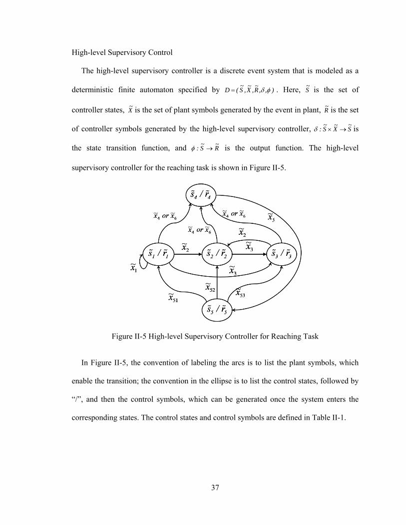
High-level Supervisory Control
The high-level supervisory controller is a discrete event system that is modeled as a
deterministic finite automaton specified by ),,R~
,X~
,S~
(D . Here, S~ is the set of
controller states, X~ is the set of plant symbols generated by the event in plant, R
~ is the set
of controller symbols generated by the high-level supervisory controller, S~
X~
S~
: is
the state transition function, and R~
S~
: is the output function. The high-level
supervisory controller for the reaching task is shown in Figure II-5.
Figure II-5 High-level Supervisory Controller for Reaching Task
In Figure II-5, the convention of labeling the arcs is to list the plant symbols, which
enable the transition; the convention in the ellipse is to list the control states, followed by
“/”, and then the control symbols, which can be generated once the system enters the
corresponding states. The control states and control symbols are defined in Table II-1.

38
Table II-1 Control States and Control Symbols
Interface in this application is designed to recognize the above-mentioned plant
symbols and control symbols. It is clear from the above discussion that the design of the
various elements of the DES plant and the DES controller is not unique and is dependent
on the task, the sensory information available from the robot-assisted rehabilitation
system, and the subject’s verbal feedback.
Results
The main focus of this paper is to present the control architecture and the high-level
supervisory controller design which was shown in Figure II-5. However, the human
intention recognition system is an important part of this new control framework that is
responsible for generating the commands to the high-level controller based on patient’s
verbal feedback to modify the task requirements. Hence we first summarize the
validation of the evaluation of human intention recognition system.
Validation of Human Intention Recognition System
Recognition accuracy of human intention recognition system has been checked with
both healthy subjects and stroke patients. First, 10 healthy subjects were invited to our
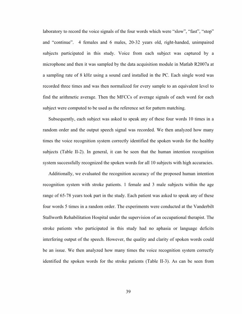
39
laboratory to record the voice signals of the four words which were “slow”, “fast”, “stop”
and “continue”. 4 females and 6 males, 20-32 years old, right-handed, unimpaired
subjects participated in this study. Voice from each subject was captured by a
microphone and then it was sampled by the data acquisition module in Matlab R2007a at
a sampling rate of 8 kHz using a sound card installed in the PC. Each single word was
recorded three times and was then normalized for every sample to an equivalent level to
find the arithmetic average. Then the MFCCs of average signals of each word for each
subject were computed to be used as the reference set for pattern matching.
Subsequently, each subject was asked to speak any of these four words 10 times in a
random order and the output speech signal was recorded. We then analyzed how many
times the voice recognition system correctly identified the spoken words for the healthy
subjects (Table II-2). In general, it can be seen that the human intention recognition
system successfully recognized the spoken words for all 10 subjects with high accuracies.
Additionally, we evaluated the recognition accuracy of the proposed human intention
recognition system with stroke patients. 1 female and 3 male subjects within the age
range of 65-78 years took part in the study. Each patient was asked to speak any of these
four words 5 times in a random order. The experiments were conducted at the Vanderbilt
Stallworth Rehabilitation Hospital under the supervision of an occupational therapist. The
stroke patients who participated in this study had no aphasia or language deficits
interfering output of the speech. However, the quality and clarity of spoken words could
be an issue. We then analyzed how many times the voice recognition system correctly
identified the spoken words for the stroke patients (Table II-3). As can be seen from
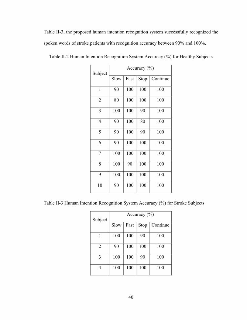
40
Table II-3, the proposed human intention recognition system successfully recognized the
spoken words of stroke patients with recognition accuracy between 90% and 100%.
Table II-2 Human Intention Recognition System Accuracy (%) for Healthy Subjects
SubjectAccuracy (%)
Slow Fast Stop Continue
1 90 100 100 100
2 80 100 100 100
3 100 100 90 100
4 90 100 80 100
5 90 100 90 100
6 90 100 100 100
7 100 100 100 100
8 100 90 100 100
9 100 100 100 100
10 90 100 100 100
Table II-3 Human Intention Recognition System Accuracy (%) for Stroke Subjects
SubjectAccuracy (%)
Slow Fast Stop Continue
1 100 100 90 100
2 90 100 100 100
3 100 100 90 100
4 100 100 100 100
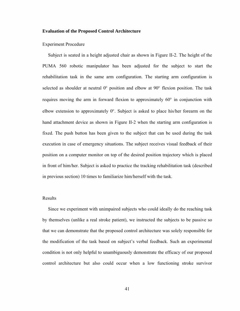
41
Evaluation of the Proposed Control Architecture
Experiment Procedure
Subject is seated in a height adjusted chair as shown in Figure II-2. The height of the
PUMA 560 robotic manipulator has been adjusted for the subject to start the
rehabilitation task in the same arm configuration. The starting arm configuration is
selected as shoulder at neutral 0 position and elbow at 90 flexion position. The task
requires moving the arm in forward flexion to approximately 60 in conjunction with
elbow extension to approximately 0. Subject is asked to place his/her forearm on the
hand attachment device as shown in Figure II-2 when the starting arm configuration is
fixed. The push button has been given to the subject that can be used during the task
execution in case of emergency situations. The subject receives visual feedback of their
position on a computer monitor on top of the desired position trajectory which is placed
in front of him/her. Subject is asked to practice the tracking rehabilitation task (described
in previous section) 10 times to familiarize him/herself with the task.
Results
Since we experiment with unimpaired subjects who could ideally do the reaching task
by themselves (unlike a real stroke patient), we instructed the subjects to be passive so
that we can demonstrate that the proposed control architecture was solely responsible for
the modification of the task based on subject’s verbal feedback. Such an experimental
condition is not only helpful to unambiguously demonstrate the efficacy of our proposed
control architecture but also could occur when a low functioning stroke survivor
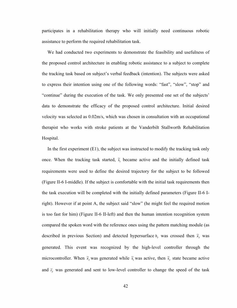
42
participates in a rehabilitation therapy who will initially need continuous robotic
assistance to perform the required rehabilitation task.
We had conducted two experiments to demonstrate the feasibility and usefulness of
the proposed control architecture in enabling robotic assistance to a subject to complete
the tracking task based on subject’s verbal feedback (intention). The subjects were asked
to express their intention using one of the following words: “fast”, “slow”, “stop” and
“continue” during the execution of the task. We only presented one set of the subjects’
data to demonstrate the efficacy of the proposed control architecture. Initial desired
velocity was selected as 0.02m/s, which was chosen in consultation with an occupational
therapist who works with stroke patients at the Vanderbilt Stallworth Rehabilitation
Hospital.
In the first experiment (E1), the subject was instructed to modify the tracking task only
once. When the tracking task started, 1s~ became active and the initially defined task
requirements were used to define the desired trajectory for the subject to be followed
(Figure II-6 I-middle). If the subject is comfortable with the initial task requirements then
the task execution will be completed with the initially defined parameters (Figure II-6 I-
right). However if at point A, the subject said “slow” (he might feel the required motion
is too fast for him) (Figure II-6 II-left) and then the human intention recognition system
compared the spoken word with the reference ones using the pattern matching module (as
described in previous Section) and detected hypersurface 2h was crossed then 2x~ was
generated. This event was recognized by the high-level controller through the
microcontroller. When 2x~ was generated while 1s~ was active, then 2s~ state became active
and 2r~ was generated and sent to low-level controller to change the speed of the task
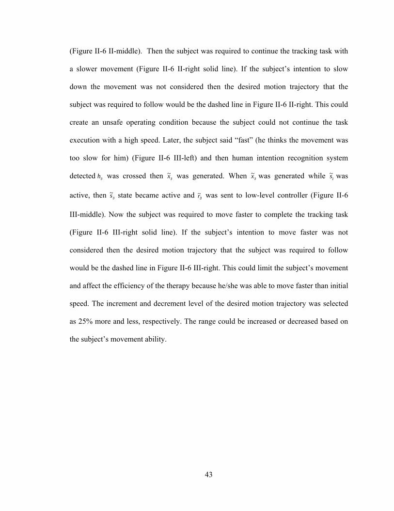
43
(Figure II-6 II-middle). Then the subject was required to continue the tracking task with
a slower movement (Figure II-6 II-right solid line). If the subject’s intention to slow
down the movement was not considered then the desired motion trajectory that the
subject was required to follow would be the dashed line in Figure II-6 II-right. This could
create an unsafe operating condition because the subject could not continue the task
execution with a high speed. Later, the subject said “fast” (he thinks the movement was
too slow for him) (Figure II-6 III-left) and then human intention recognition system
detected 3h was crossed then 3x~ was generated. When 3x~ was generated while 1s~ was
active, then 3s~ state became active and 3r~ was sent to low-level controller (Figure II-6
III-middle). Now the subject was required to move faster to complete the tracking task
(Figure II-6 III-right solid line). If the subject’s intention to move faster was not
considered then the desired motion trajectory that the subject was required to follow
would be the dashed line in Figure II-6 III-right. This could limit the subject’s movement
and affect the efficiency of the therapy because he/she was able to move faster than initial
speed. The increment and decrement level of the desired motion trajectory was selected
as 25% more and less, respectively. The range could be increased or decreased based on
the subject’s movement ability.
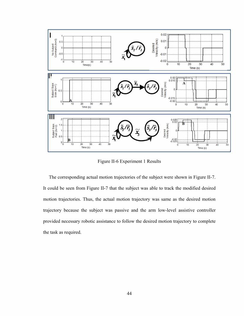
44
Figure II-6 Experiment 1 Results
The corresponding actual motion trajectories of the subject were shown in Figure II-7.
It could be seen from Figure II-7 that the subject was able to track the modified desired
motion trajectories. Thus, the actual motion trajectory was same as the desired motion
trajectory because the subject was passive and the arm low-level assistive controller
provided necessary robotic assistance to follow the desired motion trajectory to complete
the task as required.
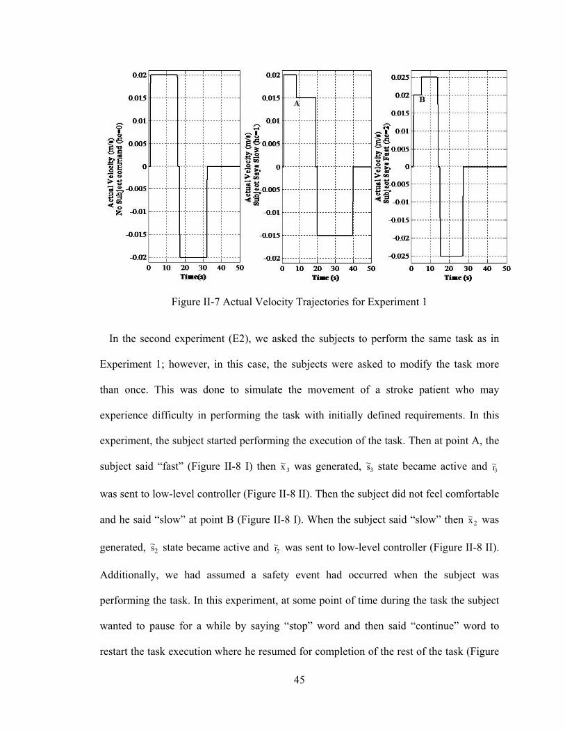
45
Figure II-7 Actual Velocity Trajectories for Experiment 1
In the second experiment (E2), we asked the subjects to perform the same task as in
Experiment 1; however, in this case, the subjects were asked to modify the task more
than once. This was done to simulate the movement of a stroke patient who may
experience difficulty in performing the task with initially defined requirements. In this
experiment, the subject started performing the execution of the task. Then at point A, the
subject said “fast” (Figure II-8 I) then 3x~ was generated, 3s~ state became active and 3r~
was sent to low-level controller (Figure II-8 II). Then the subject did not feel comfortable
and he said “slow” at point B (Figure II-8 I). When the subject said “slow” then 2x~ was
generated, 2s~ state became active and 2r~ was sent to low-level controller (Figure II-8 II).
Additionally, we had assumed a safety event had occurred when the subject was
performing the task. In this experiment, at some point of time during the task the subject
wanted to pause for a while by saying “stop” word and then said “continue” word to
restart the task execution where he resumed for completion of the rest of the task (Figure
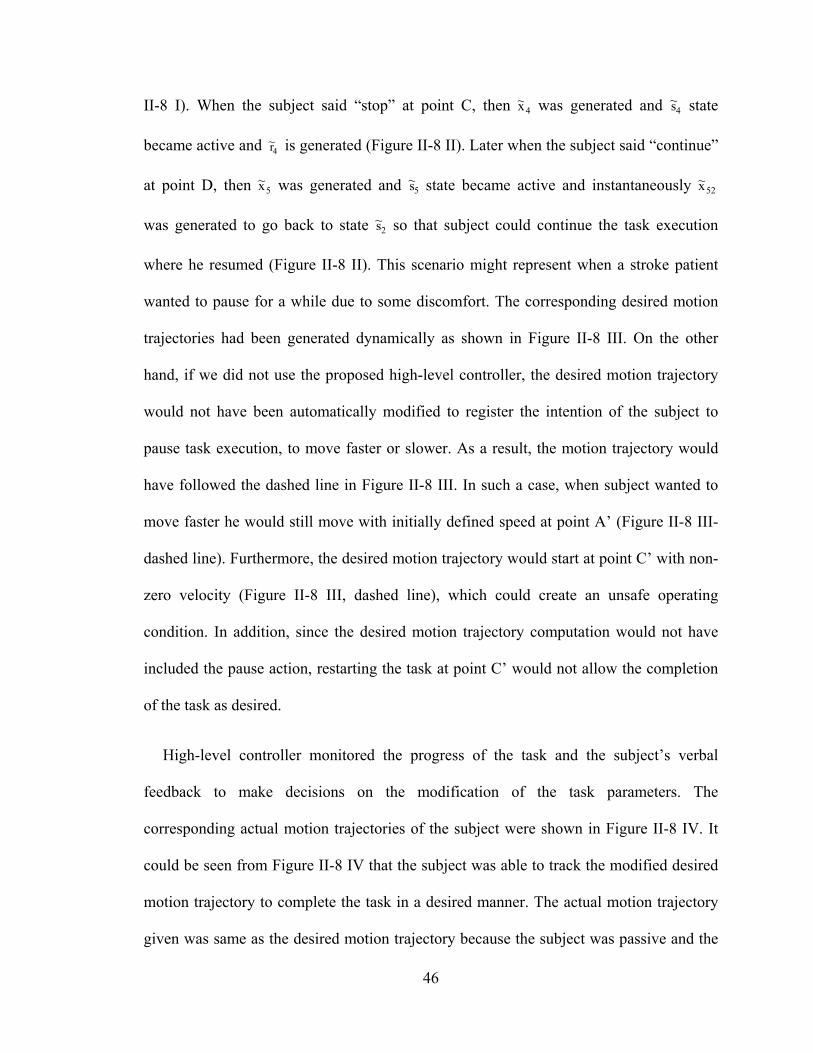
46
II-8 I). When the subject said “stop” at point C, then 4x~ was generated and 4s~ state
became active and 4r~ is generated (Figure II-8 II). Later when the subject said “continue”
at point D, then 5x~ was generated and 5s~ state became active and instantaneously 52x~
was generated to go back to state 2s~ so that subject could continue the task execution
where he resumed (Figure II-8 II). This scenario might represent when a stroke patient
wanted to pause for a while due to some discomfort. The corresponding desired motion
trajectories had been generated dynamically as shown in Figure II-8 III. On the other
hand, if we did not use the proposed high-level controller, the desired motion trajectory
would not have been automatically modified to register the intention of the subject to
pause task execution, to move faster or slower. As a result, the motion trajectory would
have followed the dashed line in Figure II-8 III. In such a case, when subject wanted to
move faster he would still move with initially defined speed at point A’ (Figure II-8 III-
dashed line). Furthermore, the desired motion trajectory would start at point C’ with non-
zero velocity (Figure II-8 III, dashed line), which could create an unsafe operating
condition. In addition, since the desired motion trajectory computation would not have
included the pause action, restarting the task at point C’ would not allow the completion
of the task as desired.
High-level controller monitored the progress of the task and the subject’s verbal
feedback to make decisions on the modification of the task parameters. The
corresponding actual motion trajectories of the subject were shown in Figure II-8 IV. It
could be seen from Figure II-8 IV that the subject was able to track the modified desired
motion trajectory to complete the task in a desired manner. The actual motion trajectory
given was same as the desired motion trajectory because the subject was passive and the
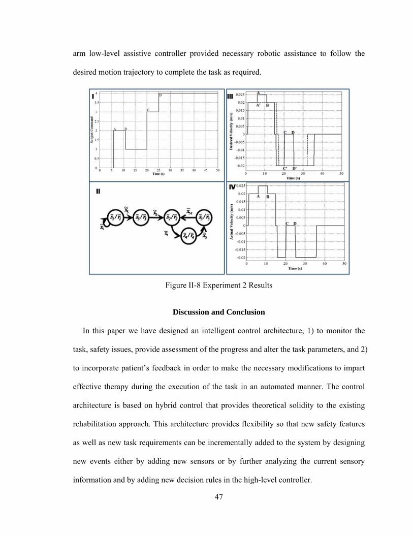
47
arm low-level assistive controller provided necessary robotic assistance to follow the
desired motion trajectory to complete the task as required.
Figure II-8 Experiment 2 Results
Discussion and Conclusion
In this paper we have designed an intelligent control architecture, 1) to monitor the
task, safety issues, provide assessment of the progress and alter the task parameters, and 2)
to incorporate patient’s feedback in order to make the necessary modifications to impart
effective therapy during the execution of the task in an automated manner. The control
architecture is based on hybrid control that provides theoretical solidity to the existing
rehabilitation approach. This architecture provides flexibility so that new safety features
as well as new task requirements can be incrementally added to the system by designing
new events either by adding new sensors or by further analyzing the current sensory
information and by adding new decision rules in the high-level controller.
48
It is also important to include patient’s feedback inside the control architecture
because patients should be able to express how they feel about the task, which will then
be used to make the necessary modifications about the presentation of the task to
accommodate any problem patients perceive during the execution of the task. However, it
is not possible to integrate spoken words into the system directly. Thus, we include
patient’s feedback as words in terms of events like other sensor events inside the control
architecture.
As could be seen from the above discussion, hybrid system based control architecture
could be useful in robot-assisted system in terms of monitoring safety, assisting patient,
and incorporating patient’s feelings, which are actually actions of the therapists during
the therapy. Thus, the presented control architecture will be helpful to automate some of
the actions of the therapists. During the therapy, if a task requirement changes or if the
patient does not feel comfortable to move his/her arm at a specified speed, then he/she
may speak out and, then a therapist/technician would need to adjust the computer code to
reflect these changes. It is conceivable that one cannot anticipate all possible events that
might occur during a rehabilitation task. The proposed hybrid system based control
architecture provides a systematic procedure to effect changes such that the task
execution could be automated. Instead of preprogramming numerous static trees based on
if-then-else rules, it provides a dynamic mechanism of generating events that leads to
necessary high-level decisions.
We have conducted experiments with unimpaired subjects to demonstrate the efficacy
of the proposed control architecture. The results have shown that the task parameters can
be determined dynamically based on subject’s spoken words and safety-related events to
49
generate the necessary motion trajectories at the required time using the proposed control
architecture. The speed of motion is used as the task parameter in this paper. However,
note that sometimes patients cannot move to the initially defined target positions because
of their limited movement ability. Thus, in the case the proposed control architecture can
be used to determine other task parameters such as a desired reaching position. Subjects
can express their intention to move further away from the initially defined target position
or closer to themselves using spoken words. In such a case, for example, the high-level
controller in the control architecture can determine the target position based on the
subject’s verbal feedback while monitoring the safety-related events. Thus, new spoken
words such as “further”, “closer” etc can be included inside the human intention
recognition system and then related events and their decision-rules can be defined inside
the control architecture as new events.
The proposed control architecture, although implemented on a PUMA 560 robot, is
independent of any particular robot and thus can be easily integrated into other existing
robot-assisted rehabilitation systems.
As a future work, it is planned to investigate the efficacy of human intention
recognition included methodology with severely impaired stroke patients and how it will
influence patients’ participation in the therapy regime.
Acknowledgment
We gratefully acknowledge the help of occupational therapist Sheila Davy of
Vanderbilt University’s Stallworth Rehabilitation Hospital for her feedback about our
50
experimental setup, the task design and giving permission to test the human intention
recognition techniques with stroke patients during this work.
References
[1] D.B. Matchar, P.W. Duncan: Cost of stroke, Stroke Clin Updates, 5, 9-12 (1994).
[2] American Heart Association: Heart and Stroke Statistical Update, http://www.Americanheart.org/statistics/stroke.htm (2006).
[3] E. Taub: Harnessing Brain Plasticity through Behavioral Techniques to Produce New Treatments in Neurorehabilitation. American Psychologist, 59(8), 692-704 (2004).
[4] H. I. Krebs, M. Ferraro, S. P. Buerger, M. J. Newbery, A. Makiyama, M. Sandmann, D. Lynch, B. T. Volpe, and N. Hogan, "Rehabilitation robotics: pilot trial of a spatial extension for MIT-Manus," J Neuroengineering Rehabil, vol. 1, p. 5, (2004).
[5] P. S. Lum, C. G. Burgar, H. F. M. Van der Loos, P. C. Shor, M. Majmundar, and R. Yap, " MIME robotic device for upper-limb neurorehabilitation in subacute stroke subjects: A follow-up study," J. of Rehab. Research & Development, vol. 43, pp. 631-642, (2006).
[6] R. Loureiro, F. Amirabdollahian, M. Topping, B. Driessen, and W. Harwin, "Upper limb mediated stroke therapy - GENTLE/s approach," Autonomous Robots, vol. 15, pp. 35-51, (2003).
[7] T. Nef, M. Guidali and R. Riener, “ARMin III – arm therapy exoskeleton with an ergonomic shoulder actuation”, Applied Bionics and Biomechanics, Vol. 6, No. 2, pp. 127–142, (2009).
[8] M. J Johnson, “Recent trends in robot-assisted therapy environments to improve real-life functional performance after stroke”, Journal of NeuroEngineering and Rehabilitation, vol. 3, No. 29, pp.1-6, (2006).
[9] D.J. Reinkensmeyer, C.T. Pang, J.A. Nessler, C.C. Painter, “Web-based telerehabilitation for the upper extremity after stroke”, IEEE Trans Neural Syst Rehabil Eng., vol. 10, No. 2, pp. 102-108, (2002).
[10] M. Mihelj, J. Podobnik, and M. Munih, “HEnRiE – Haptic Environment for Reaching and Grasping Exercise,” in Proceedings of the 2nd Biennial IEEE/RAS-EMBS International Conference on Biomedical Robotics and Biomechatronics Scottsdale, AZ, USA, October 19-22, 2008, pp. 907-912.
51
[11] J. Podobnik, M. Munih, and J. Cinkelj, “HARMiS – Hand and arm rehabilitation system,” in Proc. 7th ICDVRAT with ArtAbilitation, Maia, Portugal, 2008, pp. 237-244.
[12] D. Erol & N. Sarkar, “Coordinated Control of Assistive Robotic Devices for Activities of Daily Living Tasks”, IEEE Transactions on Neural Systems and Rehabilitation Engineering, vol. 16, pp. 278-285, 2008.
[13] D. Erol & N. Sarkar, “Intelligent Control for Robotic Rehabilitation after Stroke”, Journal of Intelligent and Robotic Systems, vol. 50, No.3, pp. 341-360, (2007).
[14] D. Erol & N. Sarkar, “Coordinated Control of Assistive Robotic Devices for Activities of Daily Living Tasks”, IEEE Transactions on Neural Systems and Rehabilitation Engineering, vol.16, No.3, pp. 278-285, (2008).
[15] D. Erol Barkana & N. Sarkar, “Towards a Smooth Human-Robot Interaction for Rehabilitation Robotic Systems”, Advanced Robotics, vol. 23, no. 12-13, pp. 1641-1662, (2009).
[16] D. Erol Barkana, “Towards Intelligent Robot-Assisted Rehabilitation Systems”, International Journal of Systems Science, DOI: 10.1080/00207720903230039, (2010).
[17] PUMA 560 Related Sites on the Internet, http://www.ee.ualberta.ca/~jasmith/puma/pumasites.html.
[18] D. Erol & N. Sarkar, “Design and Implementation of an Assistive Controller for Rehabilitation Robotic Systems”, International Journal of Advanced Robotic Systems, vol. 4, No.3, pp. 271-278, (2007).
[19] J. N. Pires. “Robot-by-voice: experiments on commanding on industrial robot using the human voice”, Industrial Robot: An International Journal, Volume 32, Number 6, pp. 505-511(7), (2005).
[20] K. Kawamura, M. Bishay, S. Bagchi, A. Saad, M. Iskarous and M. Fumoto, “Intelligent user interface for a rehabilitation robot”, Fourth International Conference on Rehabilitation Robotics, Wilmington, DE, pp. 31-35, (1994).
[21] R. Zhou, K. P. Ng and Y S Ng, “A voice controlled robot using neural network”, Proceedings of the 1994 Second Australian and New Zealand Conference on Intelligent Information System, vol. 29, issue 2, pp. 130-134, (1994).
[22] R. P. Neco, O. Reinoso, J. M. Sabater, C. Perez, L. M. Jimenez, “Advances in natural language interaction in mobile robots used for practice education”, Proceedings in World Automation Congress, vol. 15, pp. 247-252, (2004).
[23] G. W. Leng and D. P. Mittal, “A robotic system with AI”, Fourth IEEE Region 10 International Conference, TENCON, Bombay, India, pp. 999-1002, (1989).
52
[24] A. Chatterjee, K. Pulasinghe, K. Watanabe and K. Izumi, “A particle-swarm-optimized fuzzy-neural network for voice controlled robot systems”, IEEE Transactions on Industrial Electronics, vol. 52, issue 6, pp. 1478-1489, (2005).
[25] C. Jayawardena, K. Watanabe and K. Izumi, “Controlling a robot manipulator with fuzzy voice commands using a probabilistic neural network”, Neural computing and Application, issue 2, vol. 16, pp. 155-166, (2007).
[26] S. Sigurdsson, K. B. Petersen and T. Lehn-Schioler, “Mel frequency cepstral coefficients: an evaluation of robustness of MP3 encoded music”, Proceedings of the Seventh International Conference on Music Information Retieval (ISMIR), Vicoria, Canada, pp. 286-289, (2006).
[27] E. H. C. Choi, “On compensating the mel-frequency cepstral coefficients for noisy speech recognition”, Proceedings of 29th Australasian Computer Science Conference, Hobart, Australia, vol. 48, pp. 49-54, (2006).
[28] Data Acquisition Toolbox User's Guide, Matlab R2007a, Mathworks.
[29] L. R. Rabiner and M. R. Sambur, “An algorithm for determining the endpoints of isolated utterences”, The Bell System Technical Journal, vol. 54, no. 2, pp. 297-315, (1975).
[30] X. D. Koutsoukos, P. J. Antsaklis, J. A. Stiver, and M. D. Lemmon, "Supervisory control of hybrid systems," in IEEE on Special Issue on Hybrid Systems: Theory and Applications, vol. 88, pp. 1026-1049, (2000).
[31] P. J. Antsaklis and X. D. Koutsoukos, "Hybrid Systems: Review and Recent Progress," in Software-Enabled Control: Information Technologies for Dynamical Systems, T. S. a. G. Balas, Ed.: IEEE Press, pp. 1-29, (2003).
53
CHAPTER III
MANUSCRIPT II: IMPACT OF VISUAL ERROR AUGMENTATION WHEN
INTEGRATED WITH ASSIST-AS-NEEDED TRAINING METHOD IN ROBOT-
ASSISTED REHABILITATION
Furui Wang, Duygun Erol Barkana and Nilanjan Sarkar
(This work has been published in the IEEE Transactions on Neural Systems and
Rehabilitation Engineering, vol.18, no.5, pp.571-579, Oct. 2010, and partially published
in the IEEE International Conference on Rehabilitation Robotics, ICORR 2009 and the
IEEE/RSJ International Conference on Intelligent Robots and Systems, IROS 2009.)
54
Abstract
This paper investigates the impact of the integration of the visual error augmentation
training method with the assist-as-needed training method in robot-assisted rehabilitation
training of upper extremity. A robot-assisted rehabilitation system is developed that
integrates an assistive controller, which can provide robotic assistance to the participant
as and when needed, with a visual error augmentation mechanism, which amplifies the
tracking error to heighten the participant’s motivation to improve tracking accuracy. A
crossover study is performed to evaluate the impact of the integration of the visual error
augmentation method with the assist-as-needed training method. The experimental results
on unimpaired participants demonstrate that improved performance has been achieved in
the integrated training method.
Keywords: assistive controller, movement tracking training, robot-assisted
rehabilitation, assist-as-needed training method, visual error augmentation training
method
Introduction
Stroke is a highly prevalent condition [1], especially among the elderly, that results in
high costs to the individual and society [2]. According to the American Heart Association
(2009), in the U.S., approximately 795,000 people suffer a first or recurrent stroke each
year [1]. It is a leading cause of disability, commonly involving deficits of motor function.
Recent clinical results have indicated that movement assisted therapy can have a
significant beneficial impact on a large segment of the population affected by stroke or
55
other motor deficit disorders. Experimental evidence suggests that intensive movement
training of new motor tasks is required to induce long-term brain plasticity [3]. In recent
years, robot-assisted rehabilitation of stroke patients has been an active research area,
providing repetitive movement exercise and standardized delivery of therapy with the
potential of enhancing quantification of the therapeutic process [4]-[14].
Various robot-assisted rehabilitation systems are developed for the upper-limb
rehabilitation such as MIT-MANUS [4]-[6], Mirror Image Movement Enabler (MIME)
[7], [8], Assisted Rehabilitation and Measurement (ARM) Guide [9], [10] and GENTLE/s
[11]. Similarly robotic systems for wrist rehabilitation have also been reported in recent
years [12]-[14]. Studies with these robotic devices verified that robot-assisted
rehabilitation results in improved performance of functional tasks. The promising results
of robot-assisted rehabilitation systems indicate that robots could be used as effective
rehabilitation tools.
Recent research in [15] has suggested that in robot-assisted rehabilitation, assisting
every movement of a patient is not as beneficial compared to no assistance or assistance
as needed, although it is equivalent in some situations. It has also been proposed in [10],
[16] that performance-based therapy showed better results in improving patients’
impairment scores than conventional therapies. Thus, a robot-assisted rehabilitation
system could be more efficient if the robotic assistance provided to the patient is given as
and when needed based on the performance of the patient, which is called assist-as-
needed training method. It has also been demonstrated that movement tracking training
that requires cognitive processing achieved greater gains in performance than that of
movement training that did not require cognitive processing [17]. Meanwhile, latest
56
research in many models and artificial learning systems such as neural networks suggest
that error drives sensory-motor learning of a person, so that one can learn adaptation
more quickly if the error is larger [18]. Such error-driven learning processes are believed
to be central to adaptation and the acquisition of skill in human movement [19], [20]. It
has been shown that visual error augmentation can improve the rate and extent of motor
learning in healthy participants and may facilitate neuro-rehabilitation strategies that
restore function in brain injuries such as stroke [21]. Feedback distortion has also been
utilized to augment the controllability of human limb motion [22] and shown to elicit
functional improvements in patients with chronic stroke and traumatic brain injury [23].
As can be seen from the above discussion, both assist-as-needed and visual error
augmentation training methods separately have shown promising results in robot-assisted
rehabilitation of upper extremity. However, none of the existing robot-assisted
rehabilitation system, to our knowledge, is designed to integrate these two training
methods together. The objective of this work is to investigate the impact of the
integration of these two training methods in robot-assisted rehabilitation of upper
extremity. A robot-assisted rehabilitation system that was developed previously by the
authors [24] is further enhanced to integrate an assistive controller, which can provide
robotic assistance to the participant as and when needed, with a visual error augmentation
mechanism, which amplifies the tracking error to heighten the participant’s motivation to
improve tracking accuracy for this work. Twenty unimpaired participants performed a
reaching task in two sessions with only assist-as-needed training method and the
integration of the assist-as-needed with the visual error augmentation training methods in
different sequences. Nineteen out of twenty participants showed significantly improved
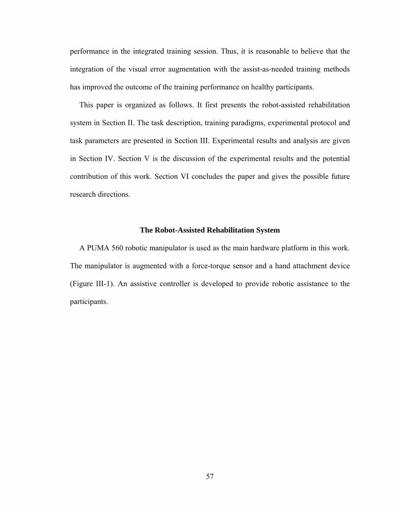
57
performance in the integrated training session. Thus, it is reasonable to believe that the
integration of the visual error augmentation with the assist-as-needed training methods
has improved the outcome of the training performance on healthy participants.
This paper is organized as follows. It first presents the robot-assisted rehabilitation
system in Section II. The task description, training paradigms, experimental protocol and
task parameters are presented in Section III. Experimental results and analysis are given
in Section IV. Section V is the discussion of the experimental results and the potential
contribution of this work. Section VI concludes the paper and gives the possible future
research directions.
The Robot-Assisted Rehabilitation System
A PUMA 560 robotic manipulator is used as the main hardware platform in this work.
The manipulator is augmented with a force-torque sensor and a hand attachment device
(Figure III-1). An assistive controller is developed to provide robotic assistance to the
participants.
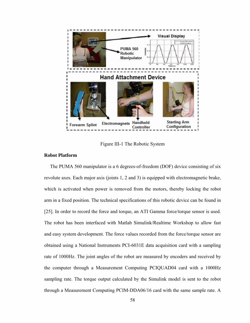
58
Figure III-1 The Robotic System
Robot Platform
The PUMA 560 manipulator is a 6 degrees-of-freedom (DOF) device consisting of six
revolute axes. Each major axis (joints 1, 2 and 3) is equipped with electromagnetic brake,
which is activated when power is removed from the motors, thereby locking the robot
arm in a fixed position. The technical specifications of this robotic device can be found in
[25]. In order to record the force and torque, an ATI Gamma force/torque sensor is used.
The robot has been interfaced with Matlab Simulink/Realtime Workshop to allow fast
and easy system development. The force values recorded from the force/torque sensor are
obtained using a National Instruments PCI-6031E data acquisition card with a sampling
rate of 1000Hz. The joint angles of the robot are measured by encoders and received by
the computer through a Measurement Computing PCIQUAD04 card with a 1000Hz
sampling rate. The torque output calculated by the Simulink model is sent to the robot
through a Measurement Computing PCIM-DDA06/16 card with the same sample rate. A
59
computer monitor is placed in front of the participant to provide visual feedback about
his/her motion trajectory during the execution of the task. Design details of the system
can be found in [24].
Hand attachment device
In order to provide robotic assistance to the participant’s upper arm, a hand attachment
device (Figure III-1 bottom) is designed where the participant’s arm is strapped into a
splint that restricts wrist and hand movement. The PUMA 560 manipulator is coupled
with the hand attachment device to provide assistance to the upper arm movement. An
ATI gamma force/torque sensor is placed between the manipulator and the aluminum
plate to provide a rigid connection and force measurement. The hand attachment device
consists of an aluminum plate with two small flat-faced electromagnets (from Magnetool
Inc.) fixed on it, and a forearm padded splint (from MooreMedical) attached to the
aluminum plate by the magnetic power. These electromagnets are rated for continuous
duty cycle (100% duty cycle) at normal room temperature. Pull rating of each magnet is
40lbs. Two electromagnets are installed to generate sufficient pulling force to keep the
splint attached to the hand attachment device. An automatic release (AU) rectifier
controller (Magnetool Inc.) has been used to provide a quick, clean release of these
electromagnets. A handheld controller, which has been connected to the AU Rectifier
Controller, is used to magnetize and demagnetize the electromagnets when the participant
wants to remove the hand attachment device from the robotic manipulator in a safe and
quick manner.
60
Assistive Controller Design
The assist-as-needed controller designed in this work is responsible for providing
robotic assistance to the participant to complete the movement tracking task in the task-
space in an accurate manner. In this controller, an outer force feedback loop is designed
around an inner position loop (Figure III-2). The tracking of the reference trajectory is
guaranteed by the inner motion control [29]. The desired force, which is given as a force
reference to the controller, is computed by a planner. The proposed controller is similar to
an impedance controller; however it allows specifying the reference time-varying force
directly. The details of the assistive controller can be found in [30], [31]. However, since
this controller is integrated with the visual error augmentation module in this work, a
brief discussion on the controller is presented below.
The equations of the motion for the robot are given by:
)(),()()( qGqqVqqMFqJu T (1)
where )q(M represents the inertia matrix, )q,q(V is the summation of the Coriolis
torques and centrifugal torques, and )(qG is the vector of gravity torques. is the
generalized joint force which is calculated using FqJu T )(- , where u is the input to the
manipulator, )(qJ is the Jacobian matrix and F is the contact force exerted by the
manipulator.
Using inverse dynamics control, the manipulator dynamics are linearized and
decoupled via feedback. Control input u to the manipulator is designed as follows:
FJqGqqVyqMu T )(),()( (2)
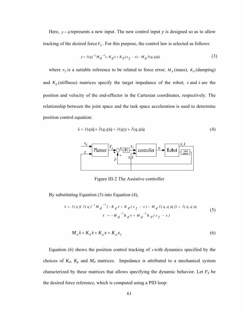
61
Here, qy represents a new input. The new control input y is designed so as to allow
tracking of the desired force dF . For this purpose, the control law is selected as follows:
)),()(()( 11 qqqJdMxfxpKxdKdMqJy (3)
where fx is a suitable reference to be related to force error; dM (mass), dK (damping)
and pK (stiffness) matrices specify the target impedance of the robot; x and x are the
position and velocity of the end-effector in the Cartesian coordinates, respectively. The
relationship between the joint space and the task space acceleration is used to determine
position control equation:
qqqJyqJqqqJqqJ ),()(),()(x (4)
xx ,fx
dFdx
xx ,
Figure III-2 The Assistive controller
By substituting Equation (3) into Equation (4),
)xfx(pKdMxdKdMx
q)q,q(J]}q)q,q(JdM)xfx(pKxdK[dM)q(J){q(Jx
11
11
(5)
fppdd xKxKxKxM (6)
Equation (6) shows the position control tracking of x with dynamics specified by the
choices of Kd, Kp and Md matrices. Impedance is attributed to a mechanical system
characterized by these matrices that allows specifying the dynamic behavior. Let Fd be
the desired force reference, which is computed using a PID loop:
62
dt
)xx(dDdt)xx(I)xx(PF d
dddddd (7)
where dx , x , dP , dI and dD are the desired position, actual position, the proportional,
integral and derivative gains of the PID position loop, respectively. The relationship
between fx and the force error is expressed in Equation (8) as:
dtFFIFFPx ididf )()( (8)
where P and I are the proportional and integral gains, respectively. The P, I, gains are
tested in our previous work to guarantee a smooth and sufficient assistance to the
participant [31]. Fi is the force applied by the human. Equations (6) and (8) are combined
to obtain below equation:
)dt)FF(I)FF(P(KxKxKxM ididppdd (9)
From Equation (9), the desired force response is achieved by controlling the position
of the manipulator.
Smooth Switching
Note that in the proposed rehabilitation task, the assistive controller switches on and
off to provide robotic assistance to the participant only when needed. In order to avoid
rough pushing and ensure smooth switching, a switching mechanism is introduced to
guarantee smooth switching for satisfactory force response [30]. This mechanism defines
the position reference at the time right after the switching occurs, which is also the input
for the inner loop of the assistive controller, to be equal to the position reference at the
63
time right before the switching occurs, so that no sudden change in position will happen
during the switching.
The control action in Equation (8) can be modified as below:
)x)t(x(*I)t(e*P)t(x),t(x)t(x ioiffffp (10)
where xfp(t) is the position reference when the assistive controller is not active, which
is equal to the current position of the human/robot x(t). xff(t) is the position reference
determined using the P and I gains when the controller is active. xi(t) represents the error
integral action dtFF id )( , and xio is the initial condition of the error integrator. ef(t) is the
force error defined as id FF . If ts is the time of switching, the position reference just
before and after the time of switching can be found using (11), respectively:
)x)t(x(*I)t(e*P)t(x
),t(x)t(x
iosisfsff
ssfp
(11)
where st is moment just before the switching occurs,
st is the moment just after the
switching occurs. The integral action associated with the assistive controller is reset
during the switching so 0)( si tx . The initial condition of the integrator is set as
Itxx sio /)( . The force error )( sf te is set to zero just after the time of the switching so
0)(* sf teP . When these conditions are substituted in Equation (11), we get Equation
(12). Equation (12) ensures that the position reference is indeed continuous during
switching, which guarantees smooth activation and deactivation of the controller.
)t(x)t(x sfpsff (12)
64
Safety Consideration of the Robotic System
Ensuring safety of the participant is a very important issue when designing a robot-
assisted rehabilitation system. Thus, in case of emergency situations, the therapist can
press a power button to stop the PUMA robot. With the quick-release hand attachment
device, the patient and/or the therapist can also quickly release the patient’s arm from the
PUMA 560 by pressing the handheld controller, which comes with the hand attachment
device, to deal with any physical safety related events. When the controller is pressed, the
electromagnets are demagnetized instantaneously and the participant is free to remove the
splint from the robot. The controller can also be operated by the therapist. Moreover,
rotation angle and torque limits of each joint of the robot are monitored inside the
software to disable the robot motion to satisfy both joint and torque limits. The switching
mechanism described above guarantees smooth switching between activation and
deactivation of the robotic assistance.
Methods
Task Design
We choose a reaching task that is commonly used for rehabilitation of upper extremity
after stroke. In this task, the participant is asked to move his/her arm in the forward
direction to reach a desired point in space and then bring it back to the starting position
repeatedly within a specified time, i.e., to follow a desired position trajectory. The
reaching task designed here requires a combination of shoulder and elbow motion which
could increase the active range of motion (AROM) in the shoulder and the elbow in
preparation for later functional reaching activities in rehabilitation. The allowable motion
65
is restricted only to the direction of the task. For example, if the task requires the
participant to move his/her arm in the Y-direction, then he/she will not be able to move
the arm in X or Z directions. The idea here is to improve the ability of the participant’s
arm movement in one direction at a time by helping him/her improve his/her ability to
complete a desired reaching task, which is an important everyday activity.
It has been shown in the literature that a movement tracking task that required
cognitive processing achieved greater gains in performance than that of movement
training that did not require cognitive processing [26]-[28]. In order to include cognitive
processing within this reaching task, the participant is asked to follow a visually
presented desired motion trajectory that is intended to command his/her concentration.
The participant receives visual feedback of both the actual and the desired position
trajectories on a computer screen, which is placed in front of him/her. The participant is
asked to pay attention to tracking the desired position trajectory as accurately as possible,
which keeps him/her focused on the task. The visual feedback is used not only to inform
the participant of how closely he/she is tracking the desired motion but also as a
motivational factor to keep him/her focused on the task. During the execution of the
reaching task, the number of times the participant needed robotic assistance to track the
desired motion is recorded.
Assist-As-Needed: Decision of Robotic Assistance Activation during Task Execution
It is intuitive that a robotic system that provides continuous assistance without
considering the patient’s actual performance will not be as effective as the one that does.
Assisting every movement of a patient has been shown to be not beneficial compared to
66
no assistance or assistance as needed, although it is equivalent in some situations [15]. It
has also been suggested in [16] that performance-based therapy showed better results in
improving patients’ impairment scores than conventional therapies. In the active-
assistance therapy with the ARM Guide system reported in [10], the stroke patients who
received robotic assistance when the tracking performance of their upper limbs fell
outside a predefined deadband showed significant improvement in the time to complete
functional tasks and in supported reaching range and velocity [10]. Thus, a robot-assisted
rehabilitation system could be more efficient if the assistance provided to the patient is
given only as and when needed. In our robot-assisted rehabilitation system, the assistive
controller is designed to provide robotic assistance based on the participant’s actual
performance of the tracking task. The idea of the assistive controller in our robotic
system is to assist the participant when his/her arm position goes out of the predefined
acceptable position band. A similar therapy algorithm was implemented with the ARM
Guide system in [10].
Initially, a desired trajectory xd is defined and then the acceptable position band
(Figure III-3) with the upper bound xupper and the lower bound xlower are calculated using
Equation (13).
)percentage*x(xx
),percentage*x(xx
ddlower
ddupper
(13)
where percentage is the value chosen to set the upper and lower bounds for the
defined position trajectory. In order to define the task position trajectories xd, a generator
block using Matlab/Simulink Blockset is developed. This block generates the minimum-
jerk position and velocity trajectories with a specified distance, maximum velocity and
67
acceleration using user defined function. If the actual position x(t) lies within the
acceptable band, then the participant is considered to be able to track the trajectory
without robotic assistance. If the actual position x is not between the upper bound xupper
and the lower bound xlower , then the assistive controller is activated to provide assistance
to bring the participant’s position back into the desired range.
However, note that each participant requires a certain amount of time (settling time) to
generate the desired motion, thus the controller should not be activated until it is
determined that the participant is not able to generate the required motion by his/her own
effort. Thus, the averages of the participant’s actual position xave (which is different from
the instantaneous position in [10]), the upper bound xupper, and the lower bound xlower are
calculated in a given time interval. These averages are used to decide whether the robotic
assistance is needed. xave, xupper_ave and xlower_ave are calculated using the equations:
f
t
it
upper)
if
s
ave_upper
ft
it
lower)
if
s
ave_lower
ft
it)
if
s
ave)t(x
tt(
tx(t),x
tt(
tx),t(x
tt(
tx
(14)
where tf , ti and ts are the final time, starting time and sampling time, respectively. The
participant’s actual position at time t is x(t).
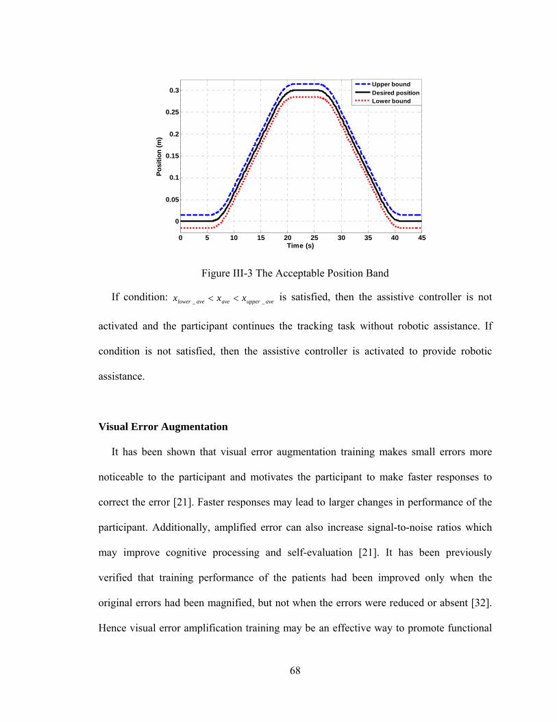
68
Figure III-3 The Acceptable Position Band
If condition: ave_upperaveave_lower xxx is satisfied, then the assistive controller is not
activated and the participant continues the tracking task without robotic assistance. If
condition is not satisfied, then the assistive controller is activated to provide robotic
assistance.
Visual Error Augmentation
It has been shown that visual error augmentation training makes small errors more
noticeable to the participant and motivates the participant to make faster responses to
correct the error [21]. Faster responses may lead to larger changes in performance of the
participant. Additionally, amplified error can also increase signal-to-noise ratios which
may improve cognitive processing and self-evaluation [21]. It has been previously
verified that training performance of the patients had been improved only when the
original errors had been magnified, but not when the errors were reduced or absent [32].
Hence visual error amplification training may be an effective way to promote functional
0 5 10 15 20 25 30 35 40 45
0
0.05
0.1
0.15
0.2
0.25
0.3
Time (s)
Po
siti
on
(m
)
Upper bound
Desired positionLower bound
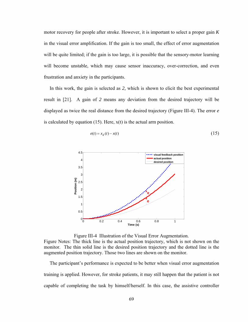
69
motor recovery for people after stroke. However, it is important to select a proper gain K
in the visual error amplification. If the gain is too small, the effect of error augmentation
will be quite limited; if the gain is too large, it is possible that the sensory-motor learning
will become unstable, which may cause sensor inaccuracy, over-correction, and even
frustration and anxiety in the participants.
In this work, the gain is selected as 2, which is shown to elicit the best experimental
result in [21]. A gain of 2 means any deviation from the desired trajectory will be
displayed as twice the real distance from the desired trajectory (Figure III-4). The error e
is calculated by equation (15). Here, x(t) is the actual arm position.
)()()( txtxte d (15)
Figure III-4 Illustration of the Visual Error Augmentation. Figure Notes: The thick line is the actual position trajectory, which is not shown on the monitor. The thin solid line is the desired position trajectory and the dotted line is the augmented position trajectory. Those two lines are shown on the monitor.
The participant’s performance is expected to be better when visual error augmentation
training is applied. However, for stroke patients, it may still happen that the patient is not
capable of completing the task by himself/herself. In this case, the assistive controller
0 0.2 0.4 0.6 0.8 10
0.5
1
1.5
2
2.5
3
3.5
4
4.5
Time (s)
Po
siti
on
(m
)
visual feedback position
actual positiondesired position
e
e
70
described in the previous section will be activated so that the robot will help the patient
come back into the acceptable band to continue the task execution. Note that the errors
fed back to the assistive controller are not amplified, which guarantees the robotic system
works in an accurate manner.
Participants
Two groups of 10 right-handed participants between the ages of 25-35 took part in the
experiment. Both groups consisted of 7 males and 3 females. None of the participants had
any motor impairment in their arms.
Protocol
Participants were seated in a height adjustable chair as shown in Figure III-1 (top left)
and were required to place their forearm on the hand attachment device as shown in
Figure III-1 (bottom left) when the starting arm configuration was fixed. The height of
the PUMA 560 robotic manipulator was adjusted for each participant to start the tracking
task in the same arm configuration. The starting arm configuration was selected as
shoulder at neutral 0º position and elbow at 90º flexion position. The task required
moving the arm in forward flexion to approximately 60º in conjunction with elbow
extension to approximately 0º and then coming back to the starting position. The release
button of the hand attachment device was given to the participants in case of emergency
situations during the task execution (Figure III-1 bottom middle). The participants
received visual feedback of the task trajectories and their own position trajectories on a
computer monitor in front of them (Figure III-1 top right).
71
We conducted two sessions of the experiment to evaluate the proposed robot-assisted
rehabilitation system with only assist-as-needed training method (AAN Session) and the
integration of the assist-as-needed with the visual error augmentation training methods
(INT Session). In both sessions, the participants used their non-dominant arms to perform
the task. This was done in order to create imperfect tracking condition so that the robotic
training had some room to elicit improvement. In the AAN Session, the aim was to
evaluate the outcome of the system with the assist-as-needed training method.
Participants were required to perform the tracking task with the robotic assistance but
without the visual error augmentation training. In INT Session, the aim was to evaluate
the outcome of the enhanced system when the visual error augmentation training was
integrated. Since the eventual aim is to apply the robot-assisted rehabilitation system to
stroke patients who are not likely to complete the task by their own efforts and may need
robotic assistance, we make robotic assistance available in both sessions in these
experiments.
In order to make a comparison of the two presented training methods, a crossover
study was performed to evaluate the difference of the training effects between the two
sessions. Group A were asked to participate in the AAN Session first and then followed
by the INT Session, while Group B were asked to participate in the INT Session first and
then followed by the AAN Session. The two sessions of both groups were conducted with
at least two weeks of interval as a washout period. The crossover design is able to
increase the precision of comparison because each participant serves his/her own control,
so the comparisons of treatment effect are based on within-participant variability (which
is usually less than the between-participant variability). Meanwhile, the carryover effect
72
between the two sessions is also investigated by the between group comparison [33]. This
study was approved by the Institutional Review Board of Vanderbilt University (IRB
#90736).
Before each session, the participant took part in a trial practice first, during which the
participant executed the same tracking task several times to get a basic understanding of
the task execution. Typically, a participant practiced 3 forward and backward motions
requiring no more than 3 minutes. Once the session started, the participants were asked to
execute the forward and backward tracking task 25 times, which was distributed into 5
training groups. Thus the participant performed the required task 5 times in each training
group without a break. The participant took a 3 to 5 minute break between two training
groups. Additionally, after finishing the INT Session, the participant took part in
additional practice without visual error augmentation to wash out the possible sensor-
motor distortion.
Task Parameters
The maximum velocity of the task was defined as 0.02m/s and the maximum
acceleration was 0.008m/s2. These two parameters were chosen in consultation with an
occupational therapist who works with stroke patients at the Vanderbilt Stallworth
Rehabilitation Hospital. The task distance was selected from 0.2m, 0.25m or 0.3m based
on the length of participants’ arms. All three parameters were necessary in creating a
desirable tracking task for each participant. Once these task parameters were decided, dx ,
dx , upperx and lowerx trajectories were generated by reference blocks in Simulink. Since the
participants were healthy subjects, the percentage of position error band was chosen as
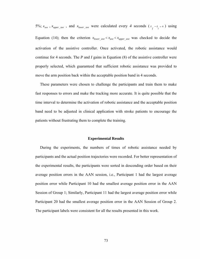
73
5%; avex , aveupperx _ , and avelowerx _ were calculated every 4 seconds ( 4if
tt ) using
Equation (14); then the criterion aveupperaveavelower xxx __ was checked to decide the
activation of the assistive controller. Once activated, the robotic assistance would
continue for 4 seconds. The P and I gains in Equation (8) of the assistive controller were
properly selected, which guaranteed that sufficient robotic assistance was provided to
move the arm position back within the acceptable position band in 4 seconds.
These parameters were chosen to challenge the participants and train them to make
fast responses to errors and make the tracking more accurate. It is quite possible that the
time interval to determine the activation of robotic assistance and the acceptable position
band need to be adjusted in clinical application with stroke patients to encourage the
patients without frustrating them to complete the training.
Experimental Results
During the experiments, the numbers of times of robotic assistance needed by
participants and the actual position trajectories were recorded. For better representation of
the experimental results, the participants were sorted in descending order based on their
average position errors in the AAN session, i.e., Participant 1 had the largest average
position error while Participant 10 had the smallest average position error in the AAN
Session of Group 1; Similarly, Participant 11 had the largest average position error while
Participant 20 had the smallest average position error in the AAN Session of Group 2.
The participant labels were consistent for all the results presented in this work.
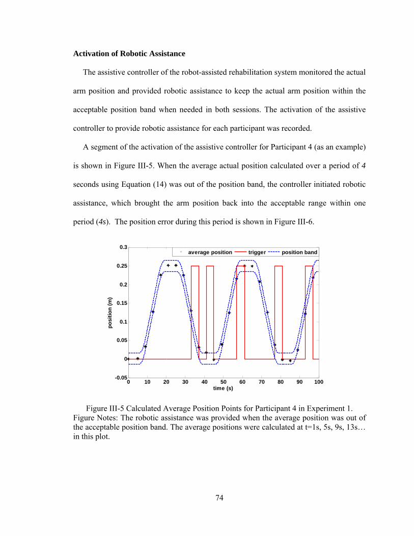
74
Activation of Robotic Assistance
The assistive controller of the robot-assisted rehabilitation system monitored the actual
arm position and provided robotic assistance to keep the actual arm position within the
acceptable position band when needed in both sessions. The activation of the assistive
controller to provide robotic assistance for each participant was recorded.
A segment of the activation of the assistive controller for Participant 4 (as an example)
is shown in Figure III-5. When the average actual position calculated over a period of 4
seconds using Equation (14) was out of the position band, the controller initiated robotic
assistance, which brought the arm position back into the acceptable range within one
period (4s). The position error during this period is shown in Figure III-6.
Figure III-5 Calculated Average Position Points for Participant 4 in Experiment 1. Figure Notes: The robotic assistance was provided when the average position was out of the acceptable position band. The average positions were calculated at t=1s, 5s, 9s, 13s… in this plot.
0 10 20 30 40 50 60 70 80 90 100-0.05
0
0.05
0.1
0.15
0.2
0.25
0.3
time (s)
po
siti
on
(m
)
average position trigger position band
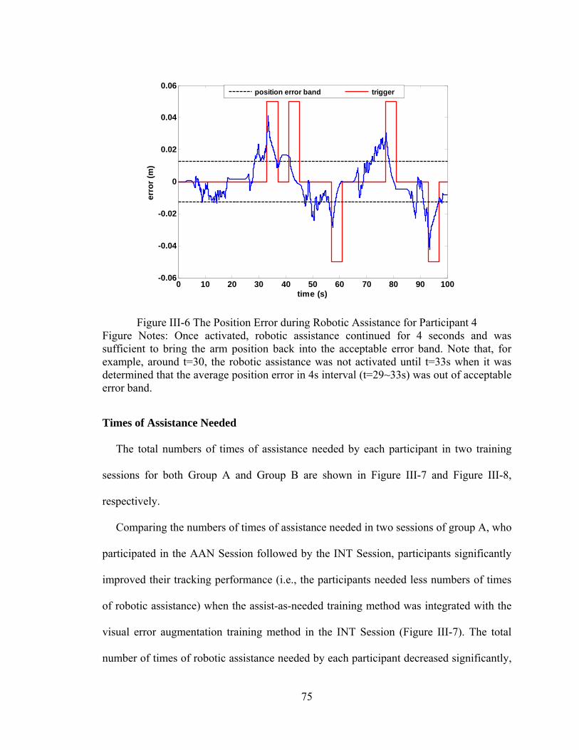
75
Figure III-6 The Position Error during Robotic Assistance for Participant 4 Figure Notes: Once activated, robotic assistance continued for 4 seconds and was sufficient to bring the arm position back into the acceptable error band. Note that, for example, around t=30, the robotic assistance was not activated until t=33s when it was determined that the average position error in 4s interval (t=29~33s) was out of acceptable error band.
Times of Assistance Needed
The total numbers of times of assistance needed by each participant in two training
sessions for both Group A and Group B are shown in Figure III-7 and Figure III-8,
respectively.
Comparing the numbers of times of assistance needed in two sessions of group A, who
participated in the AAN Session followed by the INT Session, participants significantly
improved their tracking performance (i.e., the participants needed less numbers of times
of robotic assistance) when the assist-as-needed training method was integrated with the
visual error augmentation training method in the INT Session (Figure III-7). The total
number of times of robotic assistance needed by each participant decreased significantly,
0 10 20 30 40 50 60 70 80 90 100-0.06
-0.04
-0.02
0
0.02
0.04
0.06
time (s)
erro
r (m
)
position error band trigger
76
for P1 (33.3%), P2 (56.41%), P3 (39.47%), P4 (76.67%), P5 (75.86%), P6 (23.81%), P7
(16.67%), P8 (36.84%), P9 (60%) and P10 (17.65%), in the INT Session compared to the
AAN Session. The paired t-test, which compared the group mean of the numbers of times
of robotic assistance needed by the participants in the AAN Session with that in the INT
Session, showed that the difference was statistically significant (p<0.001).
Figure III-7 Comparison of Two Sessions of Group A Figure Notes: Each participant needed less numbers of times of robotic assistance in the INT Session.
Comparing the total numbers of assistance needed in the two sessions of Group B,
who participated in the INT Session followed by the AAN Session, 9 out of 10
participants’ achieved better tracking performance (i.e., the participants needed less
numbers of times of robotic assistance) when the assist-as-needed training method was
integrated with the visual error augmentation training method in the INT Session (Figure
III-8), except for Participant 15, who showed a slight decrease in times of robotic
assistance needed (9.52%). The total number of times of robotic assistance needed by
57
39 38
30 29
2124
19
25
17
38
17
23
7 7
1620
1210
14
0
10
20
30
40
50
60
P1 P2 P3 P4 P5 P6 P7 P8 P9 P10Num
ber
of T
otal
tim
es o
f A
ssis
tanc
e N
eede
d
Participant
AAN Session
INT Session
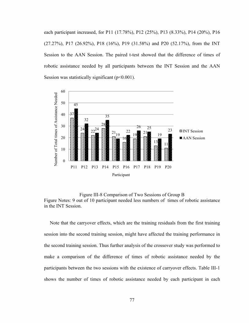
77
each participant increased, for P11 (17.78%), P12 (25%), P13 (8.33%), P14 (20%), P16
(27.27%), P17 (26.92%), P18 (16%), P19 (31.58%) and P20 (52.17%), from the INT
Session to the AAN Session. The paired t-test showed that the difference of times of
robotic assistance needed by all participants between the INT Session and the AAN
Session was statistically significant (p<0.001).
Figure III-8 Comparison of Two Sessions of Group B Figure Notes: 9 out of 10 participant needed less numbers of times of robotic assistance in the INT Session.
Note that the carryover effects, which are the training residuals from the first training
session into the second training session, might have affected the training performance in
the second training session. Thus further analysis of the crossover study was performed to
make a comparison of the difference of times of robotic assistance needed by the
participants between the two sessions with the existence of carryover effects. Table III-1
shows the number of times of robotic assistance needed by each participant in each
37
2422
28
21
1619
21
1311
45
32
24
35
1922
26 25
1923
0
10
20
30
40
50
60
P11 P12 P13 P14 P15 P16 P17 P18 P19 P20Num
ber
of T
otal
tim
es o
f A
ssis
tanc
e N
eede
d
Participant
INT Session
AAN Session
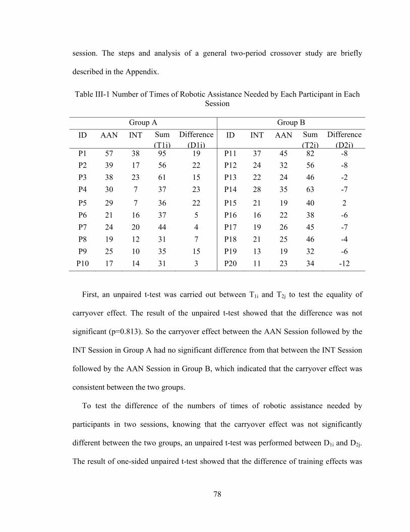
78
session. The steps and analysis of a general two-period crossover study are briefly
described in the Appendix.
Table III-1 Number of Times of Robotic Assistance Needed by Each Participant in Each Session
Group A Group B
ID AAN INT Sum (T1i)
Difference (D1i)
ID INT AAN Sum (T2j)
Difference (D2j)
P1 57 38 95 19 P11 37 45 82 -8
P2 39 17 56 22 P12 24 32 56 -8
P3 38 23 61 15 P13 22 24 46 -2
P4 30 7 37 23 P14 28 35 63 -7
P5 29 7 36 22 P15 21 19 40 2
P6 21 16 37 5 P16 16 22 38 -6
P7 24 20 44 4 P17 19 26 45 -7
P8 19 12 31 7 P18 21 25 46 -4
P9 25 10 35 15 P19 13 19 32 -6
P10 17 14 31 3 P20 11 23 34 -12
First, an unpaired t-test was carried out between T1i and T2j to test the equality of
carryover effect. The result of the unpaired t-test showed that the difference was not
significant (p=0.813). So the carryover effect between the AAN Session followed by the
INT Session in Group A had no significant difference from that between the INT Session
followed by the AAN Session in Group B, which indicated that the carryover effect was
consistent between the two groups.
To test the difference of the numbers of times of robotic assistance needed by
participants in two sessions, knowing that the carryover effect was not significantly
different between the two groups, an unpaired t-test was performed between D1i and D2j.
The result of one-sided unpaired t-test showed that the difference of training effects was
79
statistically significant (p<0.001), which indicated that better training performance were
achieved by participants in the INT Sessions than in the AAN Sessions.
Analysis of Position Error
The average absolute position errors of each participant in both groups in two sessions
were calculated using Equation (16).
,)))()((1
(5
1 5
1
,
,
,,,
i
if
istave
t
iidisif
txtxTT
e (16)
where i is the i-th training group, isT , and ifT , are the starting and final times of i-th
training group. )(, tx id and )(txi are the desired and actual positions in the i-th training
group.
In Group A, the average absolute position errors of each participant in the INT Session
was much smaller than that in the AAN Session, which meant more accurate tracking
performance was achieved by the participants in the INT Session (Figure III-9). The
paired t-test, which compared the group mean of average absolute position errors of the
participants in the AAN Session with that in the INT Session, showed that the difference
of average absolute position errors was statistically significant (p < 0.001).
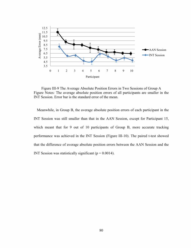
80
Figure III-9 The Average Absolute Position Errors in Two Sessions of Group A Figure Notes: The average absolute position errors of all participants are smaller in the INT Session. Error bar is the standard error of the mean.
Meanwhile, in Group B, the average absolute position errors of each participant in the
INT Session was still smaller than that in the AAN Session, except for Participant 15,
which meant that for 9 out of 10 participants of Group B, more accurate tracking
performance was achieved in the INT Session (Figure III-10). The paired t-test showed
that the difference of average absolute position errors between the AAN Session and the
INT Session was statistically significant (p = 0.0014).
3.54.55.56.57.58.59.5
10.511.512.5
0 1 2 3 4 5 6 7 8 9 10
Ave
rage
Err
or (
mm
)
Participant
AAN Session
INT Session
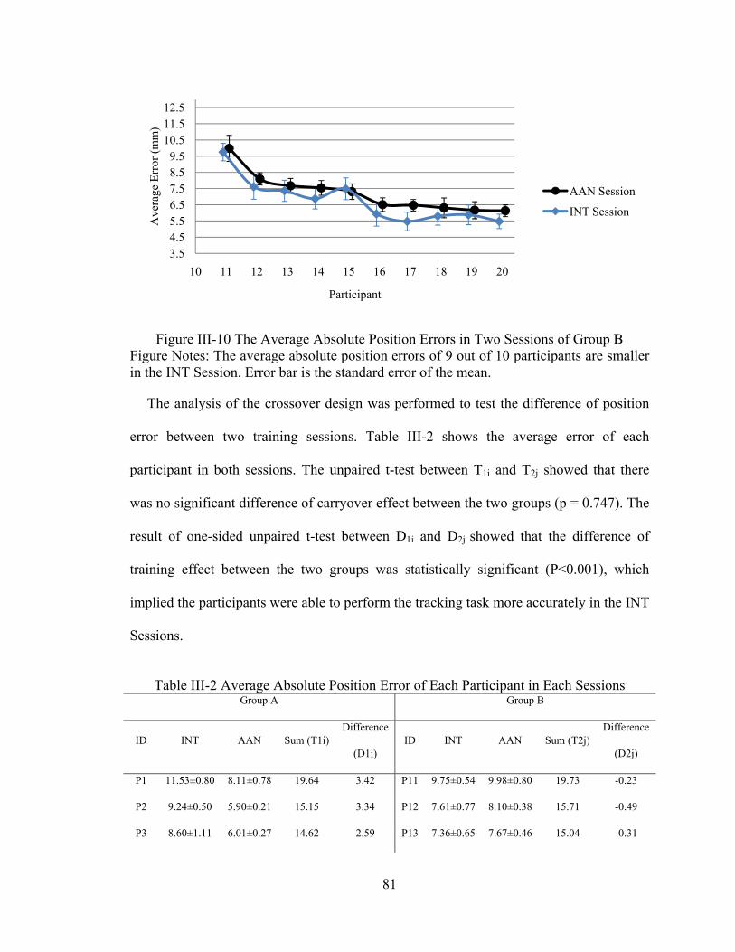
81
Figure III-10 The Average Absolute Position Errors in Two Sessions of Group B Figure Notes: The average absolute position errors of 9 out of 10 participants are smaller in the INT Session. Error bar is the standard error of the mean.
The analysis of the crossover design was performed to test the difference of position
error between two training sessions. Table III-2 shows the average error of each
participant in both sessions. The unpaired t-test between T1i and T2j showed that there
was no significant difference of carryover effect between the two groups (p = 0.747). The
result of one-sided unpaired t-test between D1i and D2j showed that the difference of
training effect between the two groups was statistically significant (P<0.001), which
implied the participants were able to perform the tracking task more accurately in the INT
Sessions.
Table III-2 Average Absolute Position Error of Each Participant in Each Sessions
Group A Group B
ID INT AAN Sum (T1i) Difference
(D1i) ID INT AAN Sum (T2j)
Difference
(D2j)
P1 11.53±0.80 8.11±0.78 19.64 3.42 P11 9.75±0.54 9.98±0.80 19.73 -0.23
P2 9.24±0.50 5.90±0.21 15.15 3.34 P12 7.61±0.77 8.10±0.38 15.71 -0.49
P3 8.60±1.11 6.01±0.27 14.62 2.59 P13 7.36±0.65 7.67±0.46 15.04 -0.31
3.54.55.56.57.58.59.5
10.511.512.5
10 11 12 13 14 15 16 17 18 19 20
Ave
rage
Err
or (
mm
)
Participant
AAN Session
INT Session
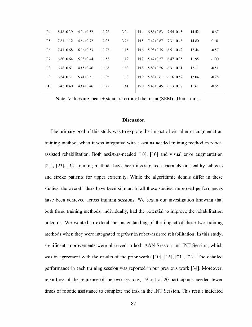
82
P4 8.48±0.39 4.74±0.52 13.22 3.74 P14 6.88±0.63 7.54±0.45 14.42 -0.67
P5 7.81±1.12 4.54±0.72 12.35 3.26 P15 7.49±0.67 7.31±0.48 14.80 0.18
P6 7.41±0.68 6.36±0.53 13.76 1.05 P16 5.93±0.75 6.51±0.42 12.44 -0.57
P7 6.80±0.64 5.78±0.44 12.58 1.02 P17 5.47±0.57 6.47±0.35 11.95 -1.00
P8 6.78±0.61 4.85±0.46 11.63 1.93 P18 5.80±0.56 6.31±0.61 12.11 -0.51
P9 6.54±0.31 5.41±0.51 11.95 1.13 P19 5.88±0.61 6.16±0.52 12.04 -0.28
P10 6.45±0.40 4.84±0.46 11.29 1.61 P20 5.48±0.45 6.13±0.37 11.61 -0.65
Note: Values are mean ± standard error of the mean (SEM). Units: mm.
Discussion
The primary goal of this study was to explore the impact of visual error augmentation
training method, when it was integrated with assist-as-needed training method in robot-
assisted rehabilitation. Both assist-as-needed [10], [16] and visual error augmentation
[21], [23], [32] training methods have been investigated separately on healthy subjects
and stroke patients for upper extremity. While the algorithmic details differ in these
studies, the overall ideas have been similar. In all these studies, improved performances
have been achieved across training sessions. We began our investigation knowing that
both these training methods, individually, had the potential to improve the rehabilitation
outcome. We wanted to extend the understanding of the impact of these two training
methods when they were integrated together in robot-assisted rehabilitation. In this study,
significant improvements were observed in both AAN Session and INT Session, which
was in agreement with the results of the prior works [10], [16], [21], [23]. The detailed
performance in each training session was reported in our previous work [34]. Moreover,
regardless of the sequence of the two sessions, 19 out of 20 participants needed fewer
times of robotic assistance to complete the task in the INT Session. This result indicated
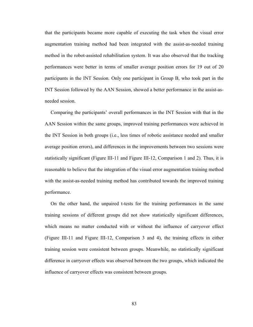
83
that the participants became more capable of executing the task when the visual error
augmentation training method had been integrated with the assist-as-needed training
method in the robot-assisted rehabilitation system. It was also observed that the tracking
performances were better in terms of smaller average position errors for 19 out of 20
participants in the INT Session. Only one participant in Group B, who took part in the
INT Session followed by the AAN Session, showed a better performance in the assist-as-
needed session.
Comparing the participants’ overall performances in the INT Session with that in the
AAN Session within the same groups, improved training performances were achieved in
the INT Session in both groups (i.e., less times of robotic assistance needed and smaller
average position errors), and differences in the improvements between two sessions were
statistically significant (Figure III-11 and Figure III-12, Comparison 1 and 2). Thus, it is
reasonable to believe that the integration of the visual error augmentation training method
with the assist-as-needed training method has contributed towards the improved training
performance.
On the other hand, the unpaired t-tests for the training performances in the same
training sessions of different groups did not show statistically significant differences,
which means no matter conducted with or without the influence of carryover effect
(Figure III-11 and Figure III-12, Comparison 3 and 4), the training effects in either
training session were consistent between groups. Meanwhile, no statistically significant
difference in carryover effects was observed between the two groups, which indicated the
influence of carryover effects was consistent between groups.
84
Table III-3 Average Value for Each Group in Each Session Group A Group B
Variable AAN Session
(AAN1) INT Session
(INT1) INT Session
(INT2) AAN Session
(AAN2)
Robotic Assistance
Needed 29.93.81 16.42.92 21.22.37 272.57
Average Error (mm)
7.960.50 5.650.34 6.770.43 7.220.38
Note: Values are mean ± standard error of the mean (SEM).
Figure III-11 The Average Number of Times of Robotic Assistance Needed in Each Session
Figure Notes: Error bars are the SEM. Note that Comparison 1 and 2 are the paired t-tests for the different sessions in the same group. Comparison 3 and 4 are the unpaired t-tests for the same sessions in different groups.
0
5
10
15
20
25
30
35
40
0 1 2 3 4
Num
ber
of ti
mes
of
Ass
ista
nce
need
ed
Comparisons
AAN 1
INT 1
INT 2
AAN 2
Significant difference between sessions (p<0.05)
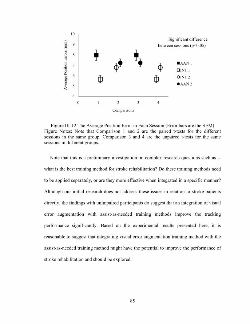
85
Figure III-12 The Average Position Error in Each Session (Error bars are the SEM) Figure Notes: Note that Comparison 1 and 2 are the paired t-tests for the different sessions in the same group. Comparison 3 and 4 are the unpaired t-tests for the same sessions in different groups.
Note that this is a preliminary investigation on complex research questions such as --
what is the best training method for stroke rehabilitation? Do these training methods need
to be applied separately, or are they more effective when integrated in a specific manner?
Although our initial research does not address these issues in relation to stroke patients
directly, the findings with unimpaired participants do suggest that an integration of visual
error augmentation with assist-as-needed training methods improve the tracking
performance significantly. Based on the experimental results presented here, it is
reasonable to suggest that integrating visual error augmentation training method with the
assist-as-needed training method might have the potential to improve the performance of
stroke rehabilitation and should be explored.
4
5
6
7
8
9
10
0 1 2 3 4
Ave
rage
Pos
itio
n E
rror
s (m
m)
Comparisons
AAN 1
INT 1
INT 2
AAN 2
Significant difference between sessions (p<0.05)
86
Conclusion
An enhanced robot-assisted rehabilitation system, with the assist-as-needed and the
visual error augmentation training methods, is evaluated with two groups of unimpaired
participants in two experimental sessions. As a crossover design, Group A participants
took part in the AAN training session followed by the INT training session, while the
Group B participants took part in the INT training session followed by the AAN training
session. The experimental results demonstrate that improved performance, in terms of
times of robotic assistance needed and average position errors, are achieved in the
integrated training session on unimpaired participants. The integration of visual error
augmentation training method with the assist-as-needed training method might have the
potential to improve the performance of stroke rehabilitation and should be further
explored.
As future work, a new assistive controller, which can adaptively choose the proper
control gains for participants with different levels of motor abilities, will be developed so
that participants can achieve better training performance with appropriate robotic
assistance. Our previous work [31] has proposed a technique that predicts proper control
gains based on parameter estimation and neural network prediction methods for each
participant. It is also possible to test various error amplification gains or error offset
values in the visual error augmentation training method to achieve a comprehensive
understanding of this training method. Additionally, an important direction for future
development involves testing the usability of the enhanced robot-assisted rehabilitation
system with stroke patients. Functional magnetic resonance imaging (fMRI) procedure
can also be introduced to investigate whether the robot-assisted rehabilitation system that
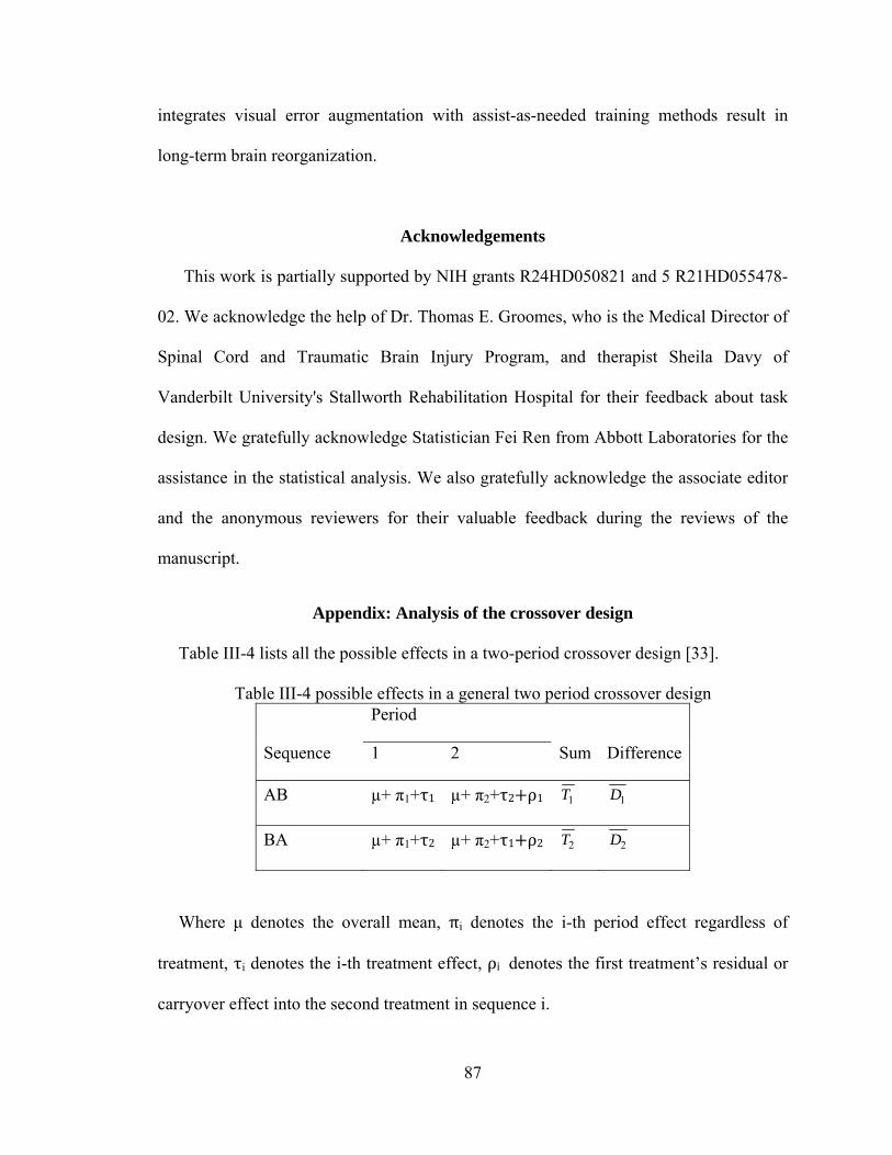
87
integrates visual error augmentation with assist-as-needed training methods result in
long-term brain reorganization.
Acknowledgements
This work is partially supported by NIH grants R24HD050821 and 5 R21HD055478-
02. We acknowledge the help of Dr. Thomas E. Groomes, who is the Medical Director of
Spinal Cord and Traumatic Brain Injury Program, and therapist Sheila Davy of
Vanderbilt University's Stallworth Rehabilitation Hospital for their feedback about task
design. We gratefully acknowledge Statistician Fei Ren from Abbott Laboratories for the
assistance in the statistical analysis. We also gratefully acknowledge the associate editor
and the anonymous reviewers for their valuable feedback during the reviews of the
manuscript.
Appendix: Analysis of the crossover design
Table III-4 lists all the possible effects in a two-period crossover design [33].
Table III-4 possible effects in a general two period crossover design Period
Sequence 1 2 Sum Difference
AB µ+ π1+τ1 µ+ π2+τ2 ρ1 1T 1D
BA µ+ π1+τ2 µ+ π2+τ1 ρ2 2T 2D
Where μ denotes the overall mean, πi denotes the i-th period effect regardless of
treatment, τi denotes the i-th treatment effect, ρi denotes the first treatment’s residual or
carryover effect into the second treatment in sequence i.
88
From the table, expectation of sum 1T and 2T ,
E( 1T ) = 2μ + π1+τ1+ π2+τ2 ρ1, E( 2T ) =2μ + π1+τ1+ π2+τ2 ρ2 . (16)
Therefore, an unbiased estimator of ρ1− ρ2, which measures the difference in carryover
effects, is,
(ρ1− ρ2)est = 1T − 2T . (17)
If ρ1=ρ2, the unbiased estimator of τ1 τ2, which measure the average difference
between treatment 1 and treatment 2, is,
(τ1− τ2)est = ( 1D − 2D )/2. (18)
If ρ1≠ρ2, the expectation of an unbiased estimator of τ1 τ2 is,
E((τ1− τ2)est) = (τ1− τ2) – (ρ1− ρ2)/2. (19)
In this case, an unbiased estimator of τ1− τ2 is,
(τ1− τ2)corrected est = 11 YX (20)
where 1X , 1Y are the measurements in Period 1 of each sequence.
So the analysis is conducted in three steps:
1) Test the equality of carryover effect between two groups with hypothesis ρ1=ρ2;
2) If the carryover effect is not equal, use only the data from the first session to test the
difference of times of assistance needed by participants in two sessions;
3) If the carryover effect is equal, use data from both sessions.
References
[1] American Heart Association: Heart and Stroke Statistical Update, http://www.Americanheart.org/statistics/stroke.htm, (2009). Updates, vol. 5, pp. 9-12, 1994.
89
[2] Matchar D.B., Duncan P.W., “Cost of stroke”, Stroke Clin Updates, 5, 9-12 (1994).
[3] Judith D. Schaechter, “Motor rehabilitation and brain plasticity after hemiparetic stroke”, Progress in Neurobiology 73 (2004) 61–72.
[4] Krebs H. I., Hogan N., Aisen M.L., Volpe B.T., “Robot–aided neurorehabilitation”, IEEE Trans. on Rehab. Eng. 6, 75-87 (1999).
[5] Krebs H.I., Palazzolo J.J., Dipietro L., Ferraro M., Krol J., Rannekleiv K. , Volpe B.T. , Hogan N., “Rehabilitation Robotics: Performance-Based Progressive Robot-Assisted Therapy”, Autonomous Robots, 15(1), 7-20 (2003).
[6] Krebs H. I, Ferraro M., Buerger S.P, Newbery M. J., Makiyama A., Sandmann M., Lynch D., Volpe B. T., Hogan N., “Rehabilitation robotics: pilot trial of a spatial extension for MIT-Manus”, Journal of NeuroEngineering and Rehabilitation. 1(5), 1-15, (2004).
[7] Burgar C.G., Lum P.S., Shor P.C., Van der Loos H.F.M., “Development of robots for rehabilitation therapy: The Palo Alto VA/Stanford experience”, J. of Rehab. Research & Development, 37(6), 663-673 (2000).
[8] Lum, P.S.; Burgar, C.G., Van der Loos, H.F.M., Shor, P.C., Majmundar M., Yap R. “MIME robotic device for upper-limb neurorehabilitation in suacute stroke subjects: A follow-up study”, J. of Rehab. Research & Development, 43(5):631-642 (2006).
[9] Reinkensmeyer D. J., Kahn L. E., Averbuch M., McKennaCole A., Schmit B.D., Rymer W.Z., “Understanding and treating arm movement impairment after chronic brain injury: Progress with the Arm Guide”, J. of Rehab. Research & Development. 37(6), 653-662 (2000).
[10] Kahn L.E., Zygman M.L.Rymer W.Z, Reinkensmeyer D.J, “Robot-assisted reaching exercise promotes arm movement recovery in chronic hemiparetic stroke: a randomized controlled pilot study”, Journal of NeuroEngineering and Rehabilitation, 3(12), 1-13 (2006).
[11] Loureiro R., Amirabdollahian F., Topping M., Driessen B., Harwin W., “Upper limb mediated stroke therapy - GENTLE/s approach”, Autonomous Robots, 15, 35-51 (2003)
[12] Hesse, S., Schulte-Tigges, G., Konrad, M., Bardeleben, A. and Werner, C., “Robot-assisted arm trainer for the passive and active practice of bilateral forearm and wrist movements in hemiparetic subjects” Arch Phys Med Rehabil, 84(6), 915–20, (2003).
[13] Charles, S., Krebs, H., Volpe, B., Lynch, D. and Hogan, N., “Wrist rehabilitation following stroke: initial clinical results,” in Proc. IEEE International Conference on Rehabilitation Robotics (ICORR’2005), Chicago, IL, USA, 13–16, (2005).
90
[14] Gupta, A., O'Malley, M. K., Patoglu, V. and Burgar, C., “Design, control and performance of RiceWrist: a force feedback wrist exoskeleton for rehabilitation and training” The International Journal of Robotics Research, 27, 233-251, (2008).
[15] Reinkensmeyer D.J., Emken J.L., Cramer S.C. “Robotics, motor learning, and neurological recovery”, Ann Rev Biomed Eng., 6, 497–525, (2006).
[16] Kahn L.E., Lum P.S., Rymer W.Z., Reinkensmeyer D.J., “Robot-assisted movement training for the stroke-impaired arm: Does it matter what the robot does?”, J Rehabil Res Dev, 43, 619-30 , (2006).
[17] Carey, J.R.; Bhatt, E. and Nagpal, A., “Neuroplasticity Promoted by Task Complexity”, Exercise and Sport Science Review, 33, 24-31, (2005).
[18] Rumelhart D. E., Hinton G. E., and Williams R. J., “Learning representations by back-propagating errors”, Nature (London), 323, pp. 533-536, (1986).
[19] Kawato M., “Feedback-error-learning neural network for supervised learning, Advanced neural computers”, R. Eckmiller, Ed. Amsterdam: North-Holland, 365-372, (1990).
[20] Wolpert D. M., Ghahramani Z., and Jordan M. I., “An internal model for sensorimotor integration, Science, 269, 1880-1882, (1995).
[21] Wei Y., Bajaj P,Scheidt R. and Patton J., “Visual Error Augmentation for Enhancing Motor Learning and Rehabilitative Relearning”, IEEE Intl. Conf. on Rehabilitation Robotics, 505-510, Chicago, USA, (2005).
[22] Dellon, B., and Matsuoka, Y. “Feedback Distortion to Augment Controllability of Human Limb Motion,” in Proceedings of Virtual Rehabilitation, 2008.
[23] Brewer, B.; Klatzky, R.; Matsuoka, Y., “Visual feedback distortion in a robotic environment for hand rehabilitation”, Brain Research Bulletin 75, 804, (2008).
[24] Erol D. and Sarkar N., “Coordinated control of assistive robotic devices for activities of daily living tasks”, IEEE Transaction on Neural and Rehabilitation Engineering, 16(3), 278-285, (2008).
[25] PUMA 560 Related Sites on the Internet, Available from: www.ee.ualberta.ca/~jasmith/puma/pumasites.html.
[26] Carey J.R., Kimberley T.J., Lewis S.M., Auerbach E., Dorsey L., Rundquist P., Ugurbil K., “Analysis of fMRI and Finger Tracking Training in Subjects with Chronic Stroke”, Brain, 125, 773-788, (2002).
[27] Carey J.R., Anderson K.M., Kimberley T.J., Lewis S.M., Auerbach E.J., Ugurbil K., “fMRI anaysis of ankle movement tracking training in Subjects with Stroke”, Exp Brain Res., 154, 281-290, (2004).
91
[28] Carey J., Durfee W., Bhatt E., Nagpal A., Weinstein S., Anderson K., Lewis S., “Tracking vs. movement Telerehabilitation training to change hand function and brain reorganization in stroke”, Neurorehabilitation and Neural Repair, (2006).
[29] Sciavicco, L. & Siciliano, B. , “Modeling and Control of Robot Manipulators”, McGrawHill, (1996).
[30] Erol D. and Sarkar N., “Intelligent Control for Robotic Rehabilitation after Stroke”, Journal of Intelligent and Robotic Systems, 50(4), 341-360, (2007).
[31] Erol D. and Sarkar N., “Smooth Human-Robot Interaction in Robot-Assisted Rehabilitation”, IEEE 10th Intl. Conf. on Rehabilitation Robotics, 5-12, (2007), Netherlands.
[32] J. L. Patton, M. E. Phillips-Stoykov, M. Stojakovich, and F. A. Mussa-Ivaldi, "Evaluation of robotic training forces that either enhance or reduce error in chronic hemiparetic stroke survivors," Experimental Brain Research, vol. Accepted pending revisions, 2004.
[33] Fleiss J. L., “The Design and Analysis of Clinical Experiments”, John Wiley & Sons Publication, (1986), ISBN-10: 0-471-82047-4.
[34] Furui Wang; Barkana, D.E.; Sarkar, N.; , "Evaluation of a robot-assisted rehabilitation system with assist-as- needed and visual error augmentation training methods," Intelligent Robots and Systems, 2009. IROS 2009. IEEE/RSJ International Conference on , pp.3555-3560, 10-15 Oct. 2009
92
CHAPTER IV
MANUSCRIPT III: DESIGN AND DEVELOPMENT OF AN ACTUATED
FINGER EXOSKELETON FOR HAND REHABILITATION FOLLOWING
STROKE
Christopher L. Jones, Furui Wang, Robert Morrison, Nilanjan Sarkar and Derek Kamper
(This work has been partially published in the IEEE International Conference on
Biomedical Robotics and Biomechatronics, BioRob 2010, and submitted to the IEEE
Transactions on Mechatronics.)

93
Abstract
Finger impairment following stroke results in significant deficits in hand manipulation
and the performance of everyday tasks. While recent advances in rehabilitation robotics
have shown promise for facilitating functional improvement, it remains unclear how best
to employ these devices to maximize benefits. Current devices for the hand lack the
capacity to fully explore the space of possible training paradigms. Particularly, they
cannot provide the independent joint control and levels of velocity and torque required.
To fill this need, we have developed a prototype for one digit, the Actuated Finger
Exoskeleton (AFX), a three degree-of-freedom robotic exoskeleton for the index finger.
This paper presents the design and development of the AFX, with performance testing
results.
Keywords: Actuated Finger Exoskeleton, Hand rehabilitation, Robot-assisted
Rehabilitation System
Introduction
Precise finger and thumb interactions are fundamental to human motor control. These
movements are used constantly in everyday tasks. Neurological disorders such as stroke
greatly impair this core function [1], directly impacting quality of life [3].
Stroke is the leading cause of serious, long-term disability in the United States [4]. Out
of an estimated 7 million stroke survivors in the U.S. [5], 30-50% will require ongoing
care or experience chronic impairment [4]. The economic costs of stroke, including direct
and indirect expenses, exceeded $73 billion for 2010 in the U.S. alone [5].
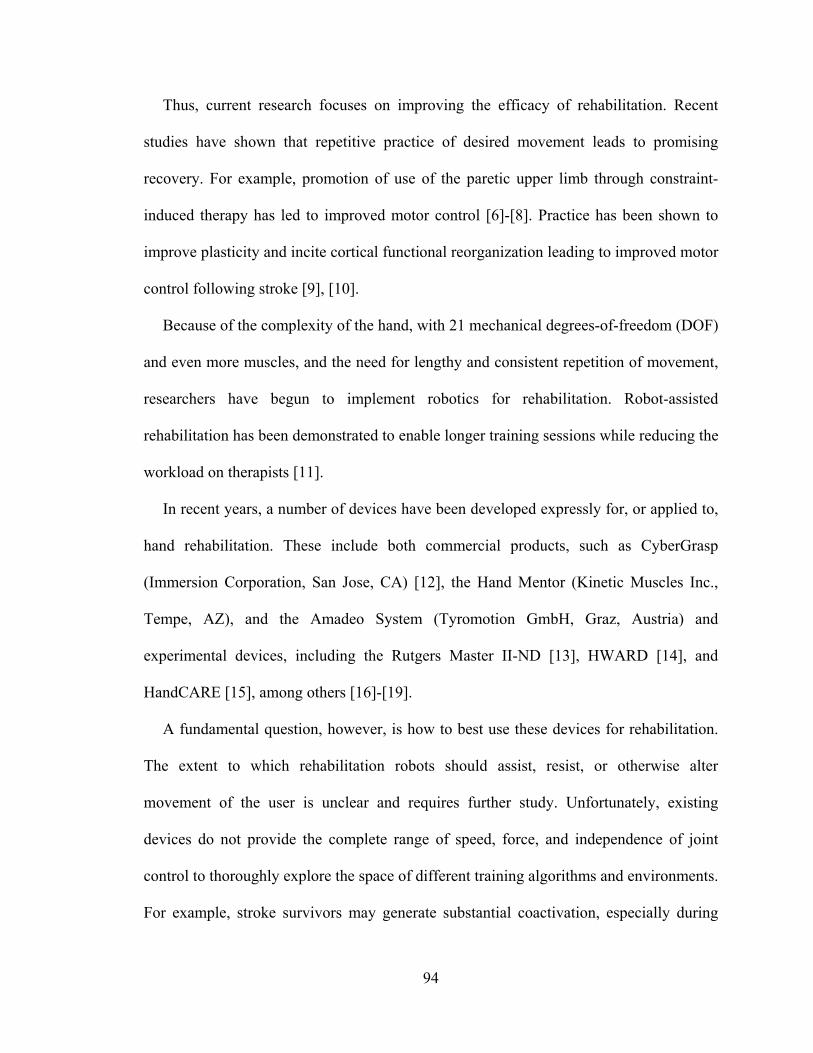
94
Thus, current research focuses on improving the efficacy of rehabilitation. Recent
studies have shown that repetitive practice of desired movement leads to promising
recovery. For example, promotion of use of the paretic upper limb through constraint-
induced therapy has led to improved motor control [6]-[8]. Practice has been shown to
improve plasticity and incite cortical functional reorganization leading to improved motor
control following stroke [9], [10].
Because of the complexity of the hand, with 21 mechanical degrees-of-freedom (DOF)
and even more muscles, and the need for lengthy and consistent repetition of movement,
researchers have begun to implement robotics for rehabilitation. Robot-assisted
rehabilitation has been demonstrated to enable longer training sessions while reducing the
workload on therapists [11].
In recent years, a number of devices have been developed expressly for, or applied to,
hand rehabilitation. These include both commercial products, such as CyberGrasp
(Immersion Corporation, San Jose, CA) [12], the Hand Mentor (Kinetic Muscles Inc.,
Tempe, AZ), and the Amadeo System (Tyromotion GmbH, Graz, Austria) and
experimental devices, including the Rutgers Master II-ND [13], HWARD [14], and
HandCARE [15], among others [16]-[19].
A fundamental question, however, is how to best use these devices for rehabilitation.
The extent to which rehabilitation robots should assist, resist, or otherwise alter
movement of the user is unclear and requires further study. Unfortunately, existing
devices do not provide the complete range of speed, force, and independence of joint
control to thoroughly explore the space of different training algorithms and environments.
For example, stroke survivors may generate substantial coactivation, especially during
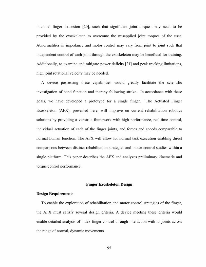
95
intended finger extension [20], such that significant joint torques may need to be
provided by the exoskeleton to overcome the misapplied joint torques of the user.
Abnormalities in impedance and motor control may vary from joint to joint such that
independent control of each joint through the exoskeleton may be beneficial for training.
Additionally, to examine and mitigate power deficits [21] and peak tracking limitations,
high joint rotational velocity may be needed.
A device possessing these capabilities would greatly facilitate the scientific
investigation of hand function and therapy following stroke. In accordance with these
goals, we have developed a prototype for a single finger. The Actuated Finger
Exoskeleton (AFX), presented here, will improve on current rehabilitation robotics
solutions by providing a versatile framework with high performance, real-time control,
individual actuation of each of the finger joints, and forces and speeds comparable to
normal human function. The AFX will allow for normal task execution enabling direct
comparisons between distinct rehabilitation strategies and motor control studies within a
single platform. This paper describes the AFX and analyzes preliminary kinematic and
torque control performance.
Finger Exoskeleton Design
Design Requirements
To enable the exploration of rehabilitation and motor control strategies of the finger,
the AFX must satisfy several design criteria. A device meeting these criteria would
enable detailed analysis of index finger control through interaction with its joints across
the range of normal, dynamic movements.
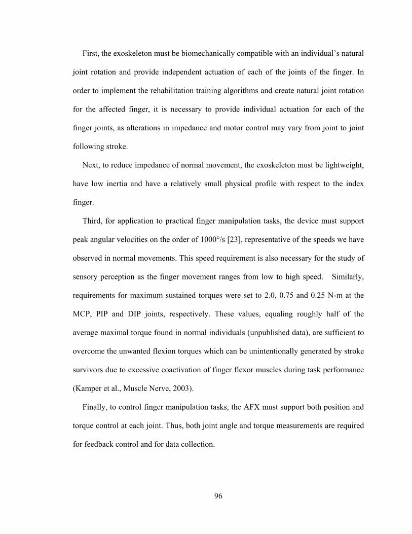
96
First, the exoskeleton must be biomechanically compatible with an individual’s natural
joint rotation and provide independent actuation of each of the joints of the finger. In
order to implement the rehabilitation training algorithms and create natural joint rotation
for the affected finger, it is necessary to provide individual actuation for each of the
finger joints, as alterations in impedance and motor control may vary from joint to joint
following stroke.
Next, to reduce impedance of normal movement, the exoskeleton must be lightweight,
have low inertia and have a relatively small physical profile with respect to the index
finger.
Third, for application to practical finger manipulation tasks, the device must support
peak angular velocities on the order of 1000°/s [23], representative of the speeds we have
observed in normal movements. This speed requirement is also necessary for the study of
sensory perception as the finger movement ranges from low to high speed. Similarly,
requirements for maximum sustained torques were set to 2.0, 0.75 and 0.25 N-m at the
MCP, PIP and DIP joints, respectively. These values, equaling roughly half of the
average maximal torque found in normal individuals (unpublished data), are sufficient to
overcome the unwanted flexion torques which can be unintentionally generated by stroke
survivors due to excessive coactivation of finger flexor muscles during task performance
(Kamper et al., Muscle Nerve, 2003).
Finally, to control finger manipulation tasks, the AFX must support both position and
torque control at each joint. Thus, both joint angle and torque measurements are required
for feedback control and for data collection.
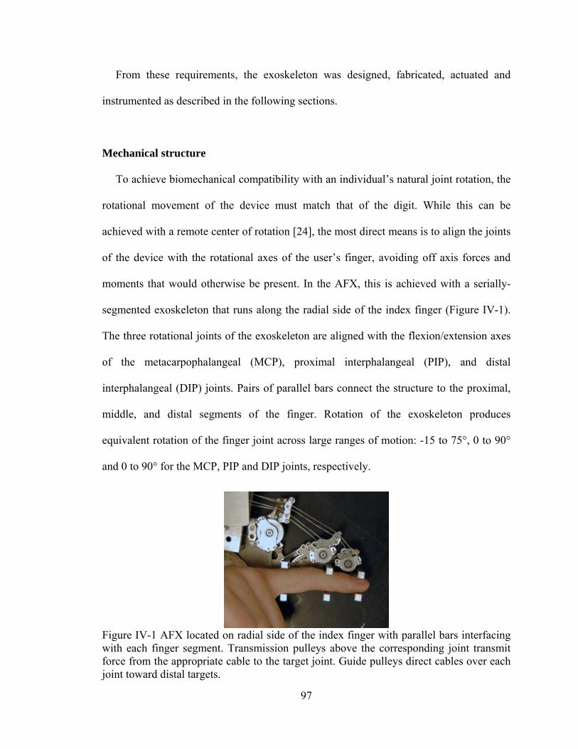
97
From these requirements, the exoskeleton was designed, fabricated, actuated and
instrumented as described in the following sections.
Mechanical structure
To achieve biomechanical compatibility with an individual’s natural joint rotation, the
rotational movement of the device must match that of the digit. While this can be
achieved with a remote center of rotation [24], the most direct means is to align the joints
of the device with the rotational axes of the user’s finger, avoiding off axis forces and
moments that would otherwise be present. In the AFX, this is achieved with a serially-
segmented exoskeleton that runs along the radial side of the index finger (Figure IV-1).
The three rotational joints of the exoskeleton are aligned with the flexion/extension axes
of the metacarpophalangeal (MCP), proximal interphalangeal (PIP), and distal
interphalangeal (DIP) joints. Pairs of parallel bars connect the structure to the proximal,
middle, and distal segments of the finger. Rotation of the exoskeleton produces
equivalent rotation of the finger joint across large ranges of motion: -15 to 75°, 0 to 90°
and 0 to 90° for the MCP, PIP and DIP joints, respectively.
Figure IV-1 AFX located on radial side of the index finger with parallel bars interfacing with each finger segment. Transmission pulleys above the corresponding joint transmit force from the appropriate cable to the target joint. Guide pulleys direct cables over each joint toward distal targets.
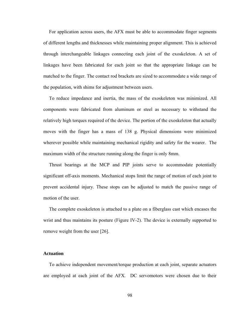
98
For application across users, the AFX must be able to accommodate finger segments
of different lengths and thicknesses while maintaining proper alignment. This is achieved
through interchangeable linkages connecting each joint of the exoskeleton. A set of
linkages have been fabricated for each joint so that the appropriate linkage can be
matched to the finger. The contact rod brackets are sized to accommodate a wide range of
the population, with shims for adjustment between users.
To reduce impedance and inertia, the mass of the exoskeleton was minimized. All
components were fabricated from aluminum or steel as necessary to withstand the
relatively high torques required of the device. The portion of the exoskeleton that actually
moves with the finger has a mass of 138 g. Physical dimensions were minimized
wherever possible while maintaining mechanical rigidity and safety for the wearer. The
maximum width of the structure running along the finger is only 8mm.
Thrust bearings at the MCP and PIP joints serve to accommodate potentially
significant off-axis moments. Mechanical stops limit the range of motion of each joint to
prevent accidental injury. These stops can be adjusted to match the passive range of
motion of the user.
The complete exoskeleton is attached to a plate on a fiberglass cast which encases the
wrist and thus maintains its posture (Figure IV-2). The device is externally supported to
remove weight from the user [26].
Actuation
To achieve independent movement/torque production at each joint, separate actuators
are employed at each joint of the AFX. DC servomotors were chosen due to their
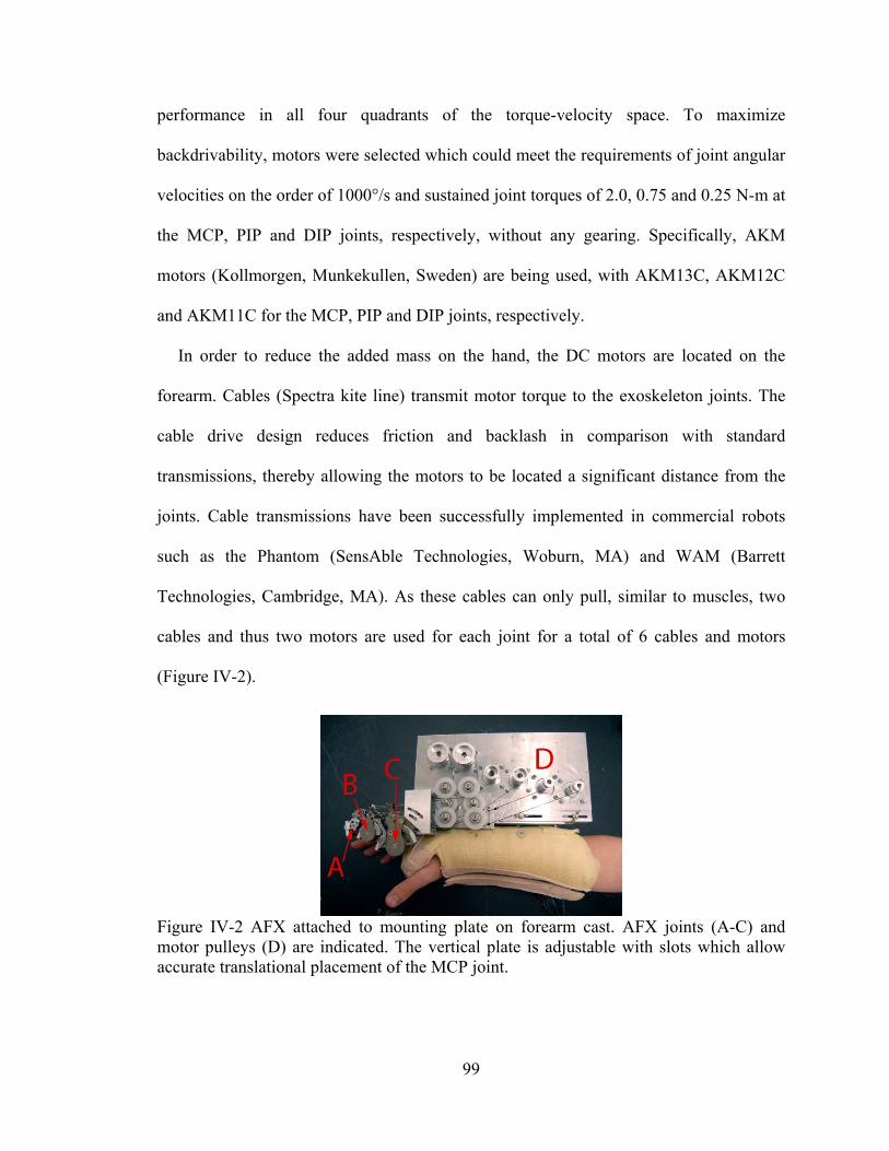
99
performance in all four quadrants of the torque-velocity space. To maximize
backdrivability, motors were selected which could meet the requirements of joint angular
velocities on the order of 1000°/s and sustained joint torques of 2.0, 0.75 and 0.25 N-m at
the MCP, PIP and DIP joints, respectively, without any gearing. Specifically, AKM
motors (Kollmorgen, Munkekullen, Sweden) are being used, with AKM13C, AKM12C
and AKM11C for the MCP, PIP and DIP joints, respectively.
In order to reduce the added mass on the hand, the DC motors are located on the
forearm. Cables (Spectra kite line) transmit motor torque to the exoskeleton joints. The
cable drive design reduces friction and backlash in comparison with standard
transmissions, thereby allowing the motors to be located a significant distance from the
joints. Cable transmissions have been successfully implemented in commercial robots
such as the Phantom (SensAble Technologies, Woburn, MA) and WAM (Barrett
Technologies, Cambridge, MA). As these cables can only pull, similar to muscles, two
cables and thus two motors are used for each joint for a total of 6 cables and motors
(Figure IV-2).
Figure IV-2 AFX attached to mounting plate on forearm cast. AFX joints (A-C) and motor pulleys (D) are indicated. The vertical plate is adjustable with slots which allow accurate translational placement of the MCP joint.
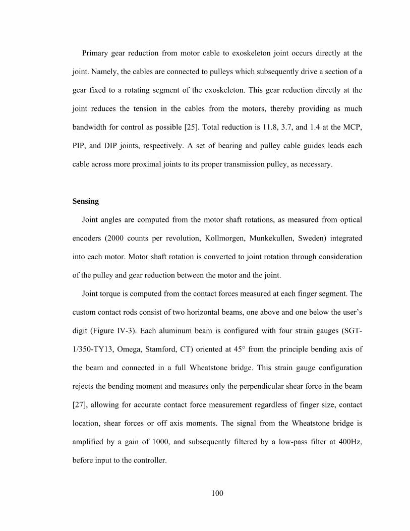
100
Primary gear reduction from motor cable to exoskeleton joint occurs directly at the
joint. Namely, the cables are connected to pulleys which subsequently drive a section of a
gear fixed to a rotating segment of the exoskeleton. This gear reduction directly at the
joint reduces the tension in the cables from the motors, thereby providing as much
bandwidth for control as possible [25]. Total reduction is 11.8, 3.7, and 1.4 at the MCP,
PIP, and DIP joints, respectively. A set of bearing and pulley cable guides leads each
cable across more proximal joints to its proper transmission pulley, as necessary.
Sensing
Joint angles are computed from the motor shaft rotations, as measured from optical
encoders (2000 counts per revolution, Kollmorgen, Munkekullen, Sweden) integrated
into each motor. Motor shaft rotation is converted to joint rotation through consideration
of the pulley and gear reduction between the motor and the joint.
Joint torque is computed from the contact forces measured at each finger segment. The
custom contact rods consist of two horizontal beams, one above and one below the user’s
digit (Figure IV-3). Each aluminum beam is configured with four strain gauges (SGT-
1/350-TY13, Omega, Stamford, CT) oriented at 45° from the principle bending axis of
the beam and connected in a full Wheatstone bridge. This strain gauge configuration
rejects the bending moment and measures only the perpendicular shear force in the beam
[27], allowing for accurate contact force measurement regardless of finger size, contact
location, shear forces or off axis moments. The signal from the Wheatstone bridge is
amplified by a gain of 1000, and subsequently filtered by a low-pass filter at 400Hz,
before input to the controller.
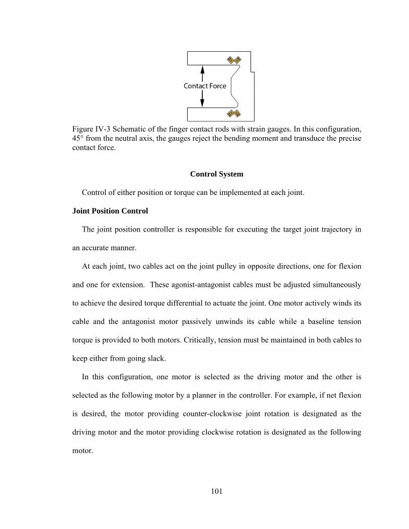
101
Figure IV-3 Schematic of the finger contact rods with strain gauges. In this configuration, 45° from the neutral axis, the gauges reject the bending moment and transduce the precise contact force.
Control System
Control of either position or torque can be implemented at each joint.
Joint Position Control
The joint position controller is responsible for executing the target joint trajectory in
an accurate manner.
At each joint, two cables act on the joint pulley in opposite directions, one for flexion
and one for extension. These agonist-antagonist cables must be adjusted simultaneously
to achieve the desired torque differential to actuate the joint. One motor actively winds its
cable and the antagonist motor passively unwinds its cable while a baseline tension
torque is provided to both motors. Critically, tension must be maintained in both cables to
keep either from going slack.
In this configuration, one motor is selected as the driving motor and the other is
selected as the following motor by a planner in the controller. For example, if net flexion
is desired, the motor providing counter-clockwise joint rotation is designated as the
driving motor and the motor providing clockwise rotation is designated as the following
motor.
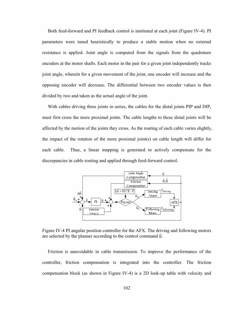
102
Both feed-forward and PI feedback control is instituted at each joint (Figure IV-4). PI
parameters were tuned heuristically to produce a stable motion when no external
resistance is applied. Joint angle is computed from the signals from the quadrature
encoders at the motor shafts. Each motor in the pair for a given joint independently tracks
joint angle, wherein for a given movement of the joint, one encoder will increase and the
opposing encoder will decrease. The differential between two encoder values is then
divided by two and taken as the actual angle of the joint.
With cables driving three joints in series, the cables for the distal joints PIP and DIP,
must first cross the more proximal joints. The cable lengths to these distal joints will be
affected by the motion of the joints they cross. As the routing of each cable varies slightly,
the impact of the rotation of the more proximal joint(s) on cable length will differ for
each cable. Thus, a linear mapping is generated to actively compensate for the
discrepancies in cable routing and applied through feed-forward control.
,
d
e
u
driving
following
du
fu
F:E?)0u(
Figure IV-4 PI angular position controller for the AFX. The driving and following motors are selected by the planner according to the control command .
Friction is unavoidable in cable transmission. To improve the performance of the
controller, friction compensation is integrated into the controller. The friction
compensation block (as shown in Figure IV-4) is a 2D look-up table with velocity and
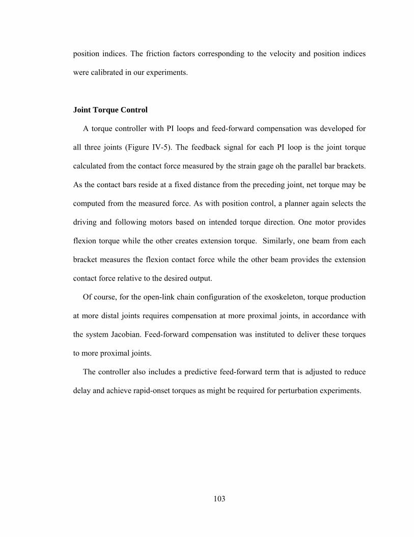
103
position indices. The friction factors corresponding to the velocity and position indices
were calibrated in our experiments.
Joint Torque Control
A torque controller with PI loops and feed-forward compensation was developed for
all three joints (Figure IV-5). The feedback signal for each PI loop is the joint torque
calculated from the contact force measured by the strain gage oh the parallel bar brackets.
As the contact bars reside at a fixed distance from the preceding joint, net torque may be
computed from the measured force. As with position control, a planner again selects the
driving and following motors based on intended torque direction. One motor provides
flexion torque while the other creates extension torque. Similarly, one beam from each
bracket measures the flexion contact force while the other beam provides the extension
contact force relative to the desired output.
Of course, for the open-link chain configuration of the exoskeleton, torque production
at more distal joints requires compensation at more proximal joints, in accordance with
the system Jacobian. Feed-forward compensation was instituted to deliver these torques
to more proximal joints.
The controller also includes a predictive feed-forward term that is adjusted to reduce
delay and achieve rapid-onset torques as might be required for perturbation experiments.
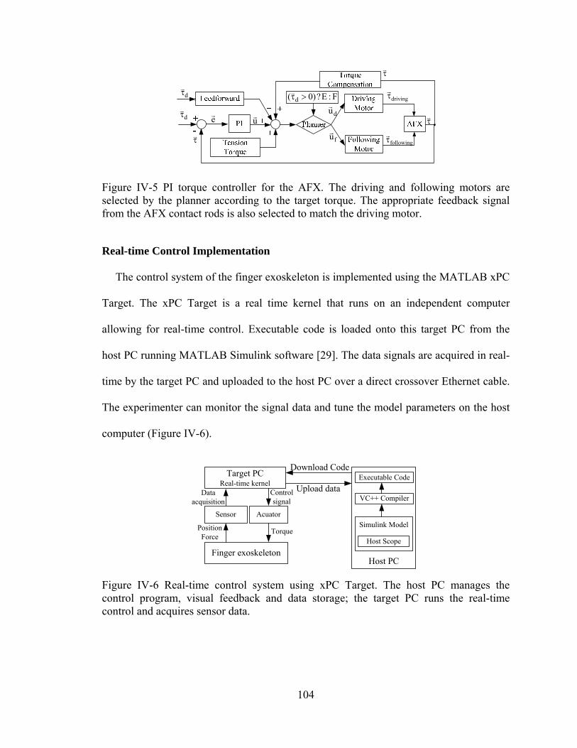
104
e
u
driving
following
d
d
du
fu
F:E?)0( d
Figure IV-5 PI torque controller for the AFX. The driving and following motors are selected by the planner according to the target torque. The appropriate feedback signal from the AFX contact rods is also selected to match the driving motor.
Real-time Control Implementation
The control system of the finger exoskeleton is implemented using the MATLAB xPC
Target. The xPC Target is a real time kernel that runs on an independent computer
allowing for real-time control. Executable code is loaded onto this target PC from the
host PC running MATLAB Simulink software [29]. The data signals are acquired in real-
time by the target PC and uploaded to the host PC over a direct crossover Ethernet cable.
The experimenter can monitor the signal data and tune the model parameters on the host
computer (Figure IV-6).
Target PCReal-time kernel
Sensor Acuator
Download Code
Finger exoskeleton
Data acquisition
Control signal
Position Force
TorqueSimulink Model
Executable Code
VC++ Compiler
Host PC
Upload data
Host Scope
Figure IV-6 Real-time control system using xPC Target. The host PC manages the control program, visual feedback and data storage; the target PC runs the real-time control and acquires sensor data.
105
A PCI-6220 ADC board (National Instruments, Austin, TX) is installed on the target
PC to perform analog-digital conversion of the signals from the tension sensors. The
CNT32-8M encoder board (CONTEC, Sunnyvale, CA) records the digital encoder
signals and the PCI-6703 DAC board (National Instruments) converts digital command
signals into the analog signals which drive the S200 motor amplifiers (Kollmorgen). All
signals are sampled at 10 kHz.
Safety Consideration
For safety, an over-damped or critically damped behavior in the joint angle control is
preferred to an under-damped system. The joint angles and torques are continuously
monitored by the control program to ensure that pre-defined limits are not exceeded.
Mechanically, guide slots restrict the range of motion of each joint and can be adjusted
to limit joint range as needed. In our design, differently sized motors are used for the
different joints. In this manner, peak motor torque can be better matched to peak
voluntary subject torque and the potential for excessive torque is minimized. An
emergency switch immediately terminates all power to the motors.
Performance Testing
Experiments were designed to test the performance of the AFX, including kinematic
control performance and force control performance.
Testing of Kinematic control performance
A two-camera setup employing high-resolution, monochrome CCD cameras (IPX-
1M48, Imperx, Inc., Boca Raton, FL) was employed to examine kinematic performance
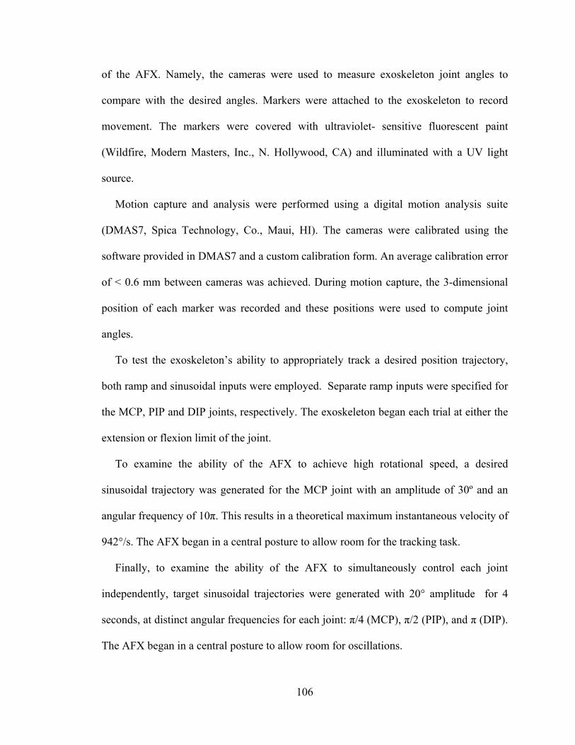
106
of the AFX. Namely, the cameras were used to measure exoskeleton joint angles to
compare with the desired angles. Markers were attached to the exoskeleton to record
movement. The markers were covered with ultraviolet- sensitive fluorescent paint
(Wildfire, Modern Masters, Inc., N. Hollywood, CA) and illuminated with a UV light
source.
Motion capture and analysis were performed using a digital motion analysis suite
(DMAS7, Spica Technology, Co., Maui, HI). The cameras were calibrated using the
software provided in DMAS7 and a custom calibration form. An average calibration error
of < 0.6 mm between cameras was achieved. During motion capture, the 3-dimensional
position of each marker was recorded and these positions were used to compute joint
angles.
To test the exoskeleton’s ability to appropriately track a desired position trajectory,
both ramp and sinusoidal inputs were employed. Separate ramp inputs were specified for
the MCP, PIP and DIP joints, respectively. The exoskeleton began each trial at either the
extension or flexion limit of the joint.
To examine the ability of the AFX to achieve high rotational speed, a desired
sinusoidal trajectory was generated for the MCP joint with an amplitude of 30º and an
angular frequency of 10π. This results in a theoretical maximum instantaneous velocity of
942°/s. The AFX began in a central posture to allow room for the tracking task.
Finally, to examine the ability of the AFX to simultaneously control each joint
independently, target sinusoidal trajectories were generated with 20° amplitude for 4
seconds, at distinct angular frequencies for each joint: π/4 (MCP), π/2 (PIP), and π (DIP).
The AFX began in a central posture to allow room for oscillations.
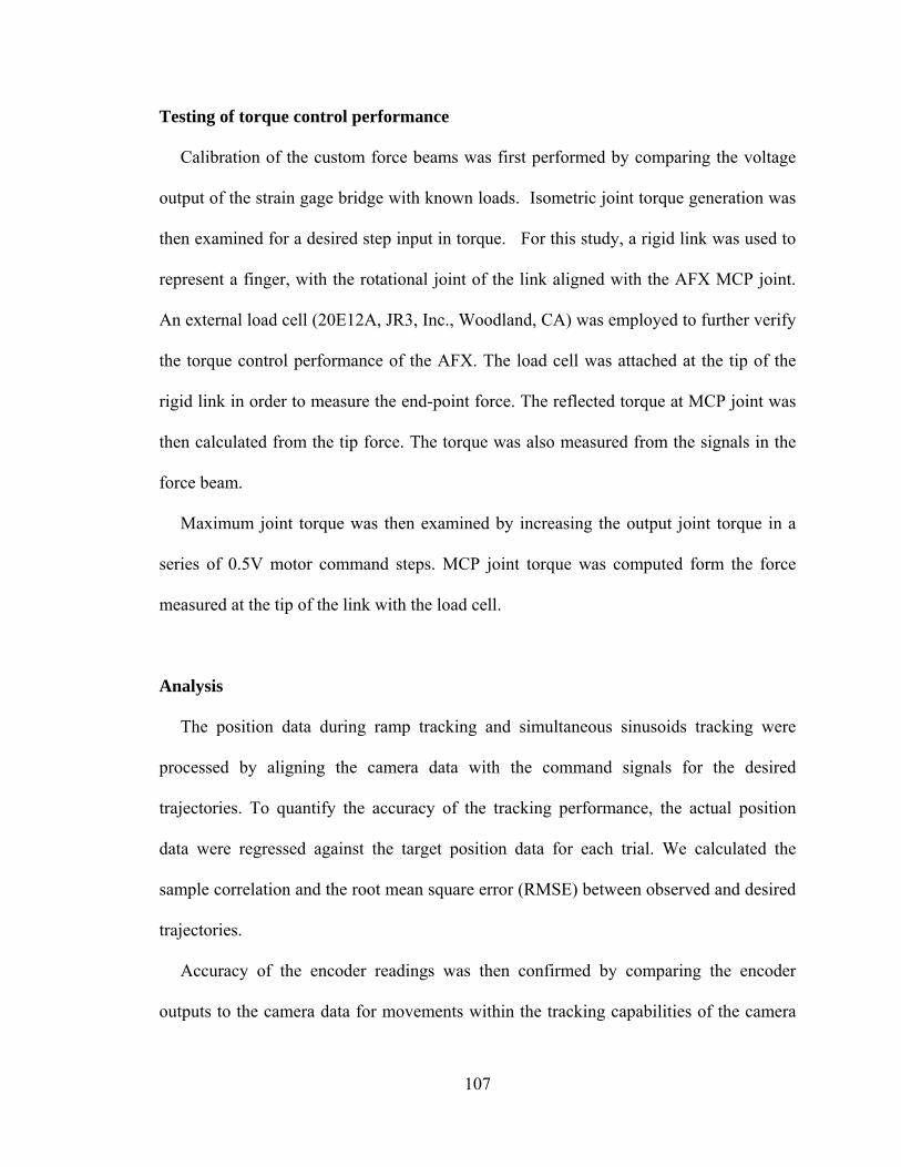
107
Testing of torque control performance
Calibration of the custom force beams was first performed by comparing the voltage
output of the strain gage bridge with known loads. Isometric joint torque generation was
then examined for a desired step input in torque. For this study, a rigid link was used to
represent a finger, with the rotational joint of the link aligned with the AFX MCP joint.
An external load cell (20E12A, JR3, Inc., Woodland, CA) was employed to further verify
the torque control performance of the AFX. The load cell was attached at the tip of the
rigid link in order to measure the end-point force. The reflected torque at MCP joint was
then calculated from the tip force. The torque was also measured from the signals in the
force beam.
Maximum joint torque was then examined by increasing the output joint torque in a
series of 0.5V motor command steps. MCP joint torque was computed form the force
measured at the tip of the link with the load cell.
Analysis
The position data during ramp tracking and simultaneous sinusoids tracking were
processed by aligning the camera data with the command signals for the desired
trajectories. To quantify the accuracy of the tracking performance, the actual position
data were regressed against the target position data for each trial. We calculated the
sample correlation and the root mean square error (RMSE) between observed and desired
trajectories.
Accuracy of the encoder readings was then confirmed by comparing the encoder
outputs to the camera data for movements within the tracking capabilities of the camera
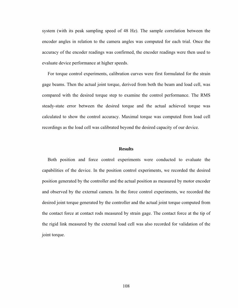
108
system (with its peak sampling speed of 48 Hz). The sample correlation between the
encoder angles in relation to the camera angles was computed for each trial. Once the
accuracy of the encoder readings was confirmed, the encoder readings were then used to
evaluate device performance at higher speeds.
For torque control experiments, calibration curves were first formulated for the strain
gage beams. Then the actual joint torque, derived from both the beam and load cell, was
compared with the desired torque step to examine the control performance. The RMS
steady-state error between the desired torque and the actual achieved torque was
calculated to show the control accuracy. Maximal torque was computed from load cell
recordings as the load cell was calibrated beyond the desired capacity of our device.
Results
Both position and force control experiments were conducted to evaluate the
capabilities of the device. In the position control experiments, we recorded the desired
position generated by the controller and the actual position as measured by motor encoder
and observed by the external camera. In the force control experiments, we recorded the
desired joint torque generated by the controller and the actual joint torque computed from
the contact force at contact rods measured by strain gage. The contact force at the tip of
the rigid link measured by the external load cell was also recorded for validation of the
joint torque.
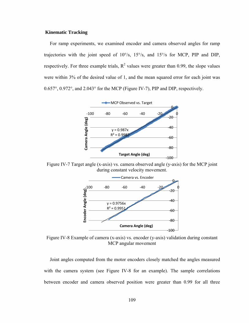
109
Kinematic Tracking
For ramp experiments, we examined encoder and camera observed angles for ramp
trajectories with the joint speed of 10°/s, 15°/s, and 15°/s for MCP, PIP and DIP,
respectively. For three example trials, R2 values were greater than 0.99, the slope values
were within 3% of the desired value of 1, and the mean squared error for each joint was
0.657°, 0.972°, and 2.043° for the MCP (Figure IV-7), PIP and DIP, respectively.
Figure IV-7 Target angle (x-axis) vs. camera observed angle (y-axis) for the MCP joint
during constant velocity movement.
Figure IV-8 Example of camera (x-axis) vs. encoder (y-axis) validation during constant
MCP angular movement
Joint angles computed from the motor encoders closely matched the angles measured
with the camera system (see Figure IV-8 for an example). The sample correlations
between encoder and camera observed position were greater than 0.99 for all three
y = 0.987xR² = 0.9987
‐100
‐80
‐60
‐40
‐20
0
‐100 ‐80 ‐60 ‐40 ‐20 0
Cam
era Angle (deg)
Target Angle (deg)
MCP Observed vs. Target
y = 0.9756xR² = 0.9951
‐100
‐80
‐60
‐40
‐20
0
‐100 ‐80 ‐60 ‐40 ‐20 0
Encoder Angle (deg)
Camera Angle (deg)
Camera vs. Encoder
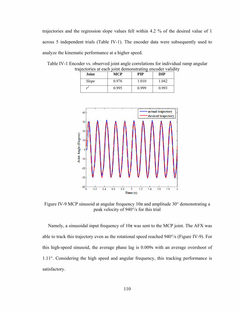
110
trajectories and the regression slope values fell within 4.2 % of the desired value of 1
across 5 independent trials (Table IV-1). The encoder data were subsequently used to
analyze the kinematic performance at a higher speed.
Table IV-1 Encoder vs. observed joint angle correlations for individual ramp angular trajectories at each joint demonstrating encoder validity
Joint MCP PIP DIP
Slope 0.976 1.010 1.042
r2 0.995 0.999 0.993
Figure IV-9 MCP sinusoid at angular frequency 10π and amplitude 30° demonstrating a peak velocity of 940°/s for this trial
Namely, a sinusoidal input frequency of 10π was sent to the MCP joint. The AFX was
able to track this trajectory even as the rotational speed reached 940°/s (Figure IV-9). For
this high-speed sinusoid, the average phase lag is 0.009s with an average overshoot of
1.11°. Considering the high speed and angular frequency, this tracking performance is
satisfactory.
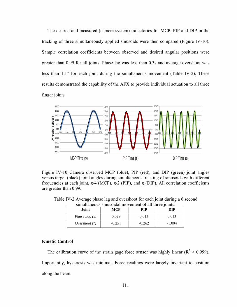
111
The desired and measured (camera system) trajectories for MCP, PIP and DIP in the
tracking of three simultaneously applied sinusoids were then compared (Figure IV-10).
Sample correlation coefficients between observed and desired angular positions were
greater than 0.99 for all joints. Phase lag was less than 0.3s and average overshoot was
less than 1.1° for each joint during the simultaneous movement (Table IV-2). These
results demonstrated the capability of the AFX to provide individual actuation to all three
finger joints.
Figure IV-10 Camera observed MCP (blue), PIP (red), and DIP (green) joint angles versus target (black) joint angles during simultaneous tracking of sinusoids with different frequencies at each joint, π/4 (MCP), π/2 (PIP), and π (DIP). All correlation coefficients are greater than 0.99.
Table IV-2 Average phase lag and overshoot for each joint during a 6 second simultaneous sinusoidal movement of all three joints.
Joint MCP PIP DIP
Phase Lag (s) 0.029 0.013 0.013
Overshoot (°) -0.251 -0.262 -1.094
Kinetic Control
The calibration curve of the strain gage force sensor was highly linear (R2 > 0.999).
Importantly, hysteresis was minimal. Force readings were largely invariant to position
along the beam.
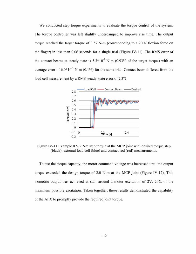
112
We conducted step torque experiments to evaluate the torque control of the system.
The torque controller was left slightly underdamped to improve rise time. The output
torque reached the target torque of 0.57 N-m (corresponding to a 20 N flexion force on
the finger) in less than 0.06 seconds for a single trial (Figure IV-11). The RMS error of
the contact beams at steady-state is 5.3*10-3 N-m (0.93% of the target torque) with an
average error of 6.0*10-3 N-m (0.1%) for the same trial. Contact beam differed from the
load cell measurement by a RMS steady-state error of 2.3%.
Figure IV-11 Example 0.572 Nm step torque at the MCP joint with desired torque step (black), external load cell (blue) and contact rod (red) measurements.
To test the torque capacity, the motor command voltage was increased until the output
torque exceeded the design torque of 2.0 N-m at the MCP joint (Figure IV-12). This
isometric output was achieved at stall around a motor excitation of 2V, 20% of the
maximum possible excitation. Taken together, these results demonstrated the capability
of the AFX to promptly provide the required joint torque.
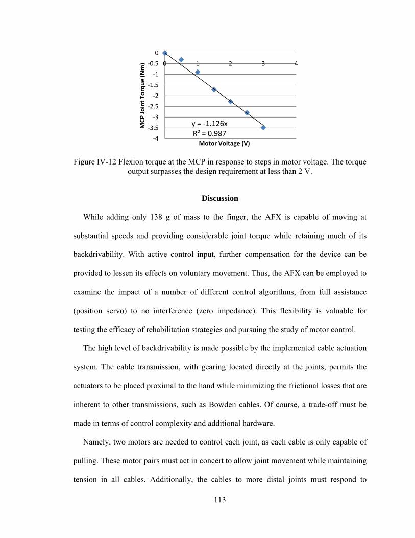
113
Figure IV-12 Flexion torque at the MCP in response to steps in motor voltage. The torque output surpasses the design requirement at less than 2 V.
Discussion
While adding only 138 g of mass to the finger, the AFX is capable of moving at
substantial speeds and providing considerable joint torque while retaining much of its
backdrivability. With active control input, further compensation for the device can be
provided to lessen its effects on voluntary movement. Thus, the AFX can be employed to
examine the impact of a number of different control algorithms, from full assistance
(position servo) to no interference (zero impedance). This flexibility is valuable for
testing the efficacy of rehabilitation strategies and pursuing the study of motor control.
The high level of backdrivability is made possible by the implemented cable actuation
system. The cable transmission, with gearing located directly at the joints, permits the
actuators to be placed proximal to the hand while minimizing the frictional losses that are
inherent to other transmissions, such as Bowden cables. Of course, a trade-off must be
made in terms of control complexity and additional hardware.
Namely, two motors are needed to control each joint, as each cable is only capable of
pulling. These motor pairs must act in concert to allow joint movement while maintaining
tension in all cables. Additionally, the cables to more distal joints must respond to
y = ‐1.126xR² = 0.987
‐4
‐3.5
‐3
‐2.5
‐2
‐1.5
‐1
‐0.5
0
0 1 2 3 4
MCP Joint To
rque (Nm)
Motor Voltage (V)

114
movement of more proximal joints; cable length is a function of all preceding joint angles
as well as the joint the cable controls. A benefit of this biomimetic actuation is the ability
to set the joint stiffness, as can be done in the human finger, as the agonist-antagonist
cable co-activation can be adjusted in tandem. Thus, impedance control can be
implemented, in addition to position or torque control.
Kinematic testing confirmed the ability of the AFX to track desired angle trajectories
over time. Tracking of the desired ramps was quite good, with R2 values of 0.99 or
greater. Tracking of the independent sinusoids simultaneously with each digit was also
successful as evidenced by correlation factors exceeding 0.99. Precise control could be
maintained even at velocities approaching maximum values in humans.
Examination of kinetic control confirmed the ability of the AFX to precisely provide a
desired isometric torque to finger joints. Even with a rapid rise time of 60 ms, RMS
steady state error was only 0.93% with an average error of 0.1%. The exoskeleton also
proved to be quite strong. Almost 3.5 N-m of torque (well exceeding the 2.0 N-m
requirement) could be achieved at the MCP joint without damage to the exoskeleton.
The sensory feedback provided by the AFX was accurate and reliable. Joint angles
derived from the encoders were in close agreement with those obtained from an external
camera system (R2 = 0.999). This suggests that inconsistencies in cable winding around
the pulleys and motor spools have minimal effect on joint angle. The torque
measurements obtained with strain gages on the contact beams closely match with the
commercial load cell (2.3% RMS steady-state error).
The AFX achieved excellent tracking of kinematic trajectories oscillating at 5 Hz and
reaching speeds close to 1000°/s. Additionally, independent trajectories could be tracked
115
with each joint simultaneously. Joint torques greater than 2 N-m could be attained. The
AFX is also contained in a platform allowing for a wide finger workspace, low
interference and arm mobility as necessary. These capabilities, which exceed those of
other current exoskeletons in power, control and feedback resolution, and impedance to
movement, will permit careful evaluation of the motor control of stroke survivors and of
different rehabilitation strategies. For example, the high achievable speeds will permit
assessment of spasticity [31] and isokinetic strength and power. The large torque
capabilities will permit evaluation of peak strength. High backdrivability with the
capacity for large perturbation forces permits implementation of force fields, such as
viscous curl fields [32], [33], for motor learning paradigms.
Future advancement of the control system will include a high-level supervisory
controller to provide different training tasks. Additional training strategies, e.g., assist-as-
needed, resist-as-needed, visual error augmentation will be integrated in this high-level
supervisory control to enhance the functionality of the AFX. Performance of the device
with human subjects will be examined next.
Acknowledgment
We acknowledge the contributions of Tom Worsnopp to the initial design of the AFX,
and Drs. Edward Colgate and Michael Peshkin from the Laboratory for Intelligent
Mechanical Systems at Northwestern University for their insight and continued support
of this project.
116
References
[1] E. G. Cruz, et al., "Kinetic and kinematic workspaces of the index finger following stroke," Brain, vol. 128, pp. 1112-21, May 2005.
[2] N. J. Seo, et al., "Altered digit force direction during pinch grip following stroke," Exp Brain Res, vol. 202, pp. 891-901, May 2010.
[3] G. S. Seale, et al., "Change in positive emotion and recovery of functional status following stroke," Rehabil Psychol, vol. 55, pp. 33-9, Feb 2010.
[4] CDC, "Outpatient rehabilitation among stroke survivors: 21 states and the District of Columbia," MMWR Morb Mortal Wkly Rep. no. 56, pp. 504-507, 2007.
[5] AHA, "Heart Disease and Stroke Statistics 2010 Update," Circulation no. 121, pp. 46-215, 2009.
[6] S. L. Wolf, et al., "Repetitive task practice: a critical review of constraint-induced movement therapy in stroke," Neurologist, vol. 8, pp. 325-38, Nov 2002.
[7] C. J. Winstein, et al., "A randomized controlled comparison of upper-extremity rehabilitation strategies in acute stroke: A pilot study of immediate and long-term outcomes," Arch Phys Med Rehabil, vol. 85, pp. 620-8, Apr 2004.
[8] S. J. Page, et al., "Efficacy of modified constraint-induced movement therapy in chronic stroke: a single-blinded randomized controlled trial," Arch Phys Med Rehabil, vol. 85, pp. 14-8, Jan 2004.
[9] J. Liepert, et al., "Motor cortex plasticity during constraint-induced movement therapy in stroke patients," Neurosci Lett, vol. 250, pp. 5-8, Jun 26 1998.
[10] J. Liepert, et al., "Treatment-induced cortical reorganization after stroke in humans," Stroke vol. 31, pp. 1210-1216, 2000.
[11] L. Pignolo, "Robotics in neuro-rehabilitation," J Rehabil Med, vol. 41, no. 12, pp. 955-960, 2009.
[12] S. V. Adamovich, et al., "Design of a complex virtual reality simulation to train finger motion for persons with hemiparesis: a proof of concept study," J Neuroeng Rehabil, vol. 6, p. 28, 2009.
[13] D. Jack, et al., "Virtual reality-enhanced stroke rehabilitation," IEEE Trans Neural Syst Rehabil Eng, vol. 9, pp. 308-18, Sep 2001.
[14] C. D. Takahashi, et al., "Robot-based hand motor therapy after stroke," Brain, vol. 131, pp. 425-37, Feb 2008.
[15] L. Dovat, et al., "HandCARE: a cable-actuated rehabilitation system to train hand function after stroke," IEEE Trans Neural Syst Rehabil Eng, vol. 16, pp. 582-91, Dec 2008.
117
[16] A.Wedge, and G. Hommel, "Development and control of a hand exoskeleton for rehabilitation of hand injuries," IEEE/RSJ International Conference on Intelligent Robots and Systems, pp. 3046 - 3051 2005.
[17] I. Sarakoglou, et al., "Occupational and physical therapy using a hand exoskeleton based exerciser," IEEE/RSJ International Conference on Intelligent Robots and Systems Proceedings, vol. 3, pp. 2973 – 2978, 2004.
[18] M. DiCicco, et al., "Comparison of control strategies for an EMG-controlled orthotic exoskeleton for the hand," IEEE International Conference on Robotics and Automation, vol. 2, pp. 1622-1627 2004.
[19] H. Kawasaki, et al., "Development of a hand motion assist robot for rehabilitation therapy by patient self-motion control," IEEE 10th Intl Conf Rehab Rob, pp. 234-240, 2007.
[20] D. G. Kamper and W. Z. Rymer, "Impairment of voluntary control of finger motion following stroke: role of inappropriate muscle coactivation," Muscle Nerve, vol. 24, pp. 673-81, May 2001.
[21] D. H. Saunders, et al., "Association of activity limitations and lower-limb explosive extensor power in ambulatory people with stroke," Arch Phys Med Rehabil, vol. 89, pp. 677-83, Apr 2008.
[22] D. G. Kamper, et al., "Relative contributions of neural mechanisms versus muscle mechanics in promoting finger extension deficits following stroke," Muscle Nerve, vol. 28, pp. 309-18, Sep 2003.
[23] B. Gutnik, et al., "Power of performance of the thumb adductor muscles: effect of laterality and gender," Medicina (Kaunas), vol. 42, pp. 653-60, 2006.
[24] R. Baumann, et al., "The PantoScope: a spherical remote-center-of- motion parallel manipulator for force reflection," IEEE International Conference on Robotics and Automation,, vol.1, pp. 20-25, Apr 1997.
[25] W. Townsend and J. Salisbury, "Mechanical bandwidth as a guideline to high-performance manipulator design," IEEE International Conference on Robotics and Automation, 1989.
[26] Iwamuro BT, Cruz EG, Connelly LL, Fischer HC, Kamper DG., Effect of a gravity-compensating orthosis on reaching after stroke: evaluation of the Therapy Assistant WREX. Arch Phys Med Rehabil. 2008 Nov; 89(11):2121-8.
[27] Omega WEB Technical Reference, http://www.omega.com/faq/ pressure/pdf/positioning.pdf
[28] J. J. Craig, Introduction to Robotics: Mechanics and Control. Reading, MA: Addison-Wesley, 1989.
118
[29] T. K. Podder and N. Sarkar, "A unified dynamics-based motion planning algorithm for autonomous underwater vehicle-manipulator systems (UVMS)," Robotica, vol. 22, pp. 117-128, 2004.
[30] xPC Target documents, Mathworks, http://www.mathworks.com/ access/helpdesk/help/toolbox/xpc/ref_endref_end.
[31] D. G. Kamper and W. Z. Rymer, "Quantitative features of the stretch response of extrinsic finger muscles in hemiparetic stroke," Muscle Nerve, vol. 23, pp. 954-61, Jun 2000.
[32] R. A. Scheidt, et al., "Persistence of motor adaptation during constrained, multi-joint, arm movements," J Neurophysiol, vol. 84, pp. 853-62, Aug 2000.
[33] J. L. Patton, et al., "Evaluation of robotic training forces that either enhance or reduce error in chronic hemiparetic stroke survivors," Exp Brain Res, vol. 168, pp. 368-83, Jan 2006.
119
CHAPTER V
MANUSCRIPT IV: DESIGN AND DEVELOPMENT OF AN ACTUATED
THUMB EXOSKELETON FOR HAND REHABILITATION FOLLOWING
STROKE
Furui Wang, Milind Shastri, Christopher L. Jones, Derek G. Kamper, and Nilanjan Sarkar
(This work has been partially published in the 2011 IEEE/RAS International
Conference on Robotics and Automation, ICRA 2011, and is in preparation for
submission to the IEEE Transaction ons Mechatronics.)
120
Abstract
Chronic hand impairment is a common target for rehabilitation following stroke. This
paper presents an actuated thumb exoskeleton (ATX) to facilitate research in hand
rehabilitation therapy. The ATX presented in this work permits independent bi-
directional actuation in each of the 5 degrees-of-freedom (DOF) of the thumb using a
mechanism that has 5 active DOF and 3 passive DOF. The ATX is able to provide
considerable joint torques for the user while still allowing backdrivability through
flexible shaft transmission. A prototype was built and experiments were conducted to
evaluate the closed-loop position control. Further improvement and future work are
discussed.
Introduction
Hand impairment is a prevalent outcome for a variety of neuromuscular disorders,
such as stroke. Up to 795,000 people in the U.S. experience a stroke each year [1]. Of
these, 60-75% will live beyond one year after the incidence, resulting in a current stroke
population of 7 million [1]-[3]. Arm function is acutely impaired in a large majority of
those diagnosed with stroke [4]-[6]. Furthermore, acute hemiparesis presages chronic
hemiparesis in over 40% of individuals [4], [5]. Chronic deficits are prevalent in the
distal upper extremities, especially with regard to finger extension [7].
This distal limb impairment can be especially disabling, as proper hand function is
crucial to manual exploration and manipulation of the environment. Indeed, loss of hand
function due to neuromuscular disorders frequently prevents effective self-care and limits
employment opportunities. One study reported that more than half of the subjects they
121
observed were dependent on others for help in the activities of daily living six months
post-stroke [8].
An assortment of interventions has been tried in an effort to improve function or to
treat the resulting peripheral alterations following stroke. Those with the most success to
date tend to focus on repetitive practice. Indeed, numerous studies employing the
constraint-induced technique, in which focus is placed on intensive practice with the
impaired arm without using the less impaired arm, have shown improvement in hand
capabilities [9]-[11]. This supports the observations in animal models of stroke in which
practice appears to be the primary factor leading to synaptogenesis and brain plasticity
[12]-[14]. Indeed, imaging performed during constraint-induced training studies has
shown evidence of cortical plasticity following the training [15], [16].
Unfortunately, many stroke survivors do not possess sufficient sensorimotor control to
practice the desired movements. For the upper extremity, robots have been created to
assist with therapeutic training of the wrist, arm and shoulder [17]-[21]. It has been
reported that robot-delivered sensorimotor training enhanced the motor performance of
the exercised shoulder and elbow with improved functional outcomes [22] and that
practicing with a robot that assisted reaching movements helped the users learn how to
generate smoother unaided reaching trajectories [23].
A fundamental question, in robot-assisted rehabilitation, is how to best use these
robotic devices to facilitate rehabilitation. Should the device assist or resist movement?
Should movement error actually be augmented, as some have suggested [24]? Should
emphasis be placed on practice of movement of individual joints [25] or on the
122
coordination of multiple joints? In order to answer these questions for rehabilitation of
the hand, a device is needed to provide precise control of individual hand joint.
In recent years, a number of devices have been developed expressly for or applied to
hand rehabilitation. These include both commercial products, such as CyberGrasp
(Immersion Corporation, San Jose, CA) [26], the Hand Mentor (Kinetic Muscles Inc.,
Tempe, AZ) and the Amadeo System (Tyromotion GmbH, Graz, Austria), and
experimental devices, such as Rutgers Master II-ND [27], HWARD [28] and HandCARE
[29], among others [30]-[33].
However, the majority of the developed systems do not provide individual control of
the thumb. The thumb is a unique digit in the hand typically modeled with five degrees-
of-freedom (DOF) [34]-[37]. The role of thumb is crucial in hand function as it is
involved in 40-50% of hand function, which is almost equivalents the function of all
other fingers. Some devices allow individual control of the thumb [30], [33], however,
these devices do not have sufficient speed or torque to thoroughly explore the space of
different training algorithms and environments. For example, stroke survivors may
generate substantial coactivation, especially during intended thumb extension [38], such
that significant joint torques may need to be provided by the exoskeleton to overcome the
misapplied joint torques of the user. Abnormalities in impedance and motor control may
vary from joint to joint such that independent control of each joint through the
exoskeleton may be beneficial for training. Additionally, to examine and mitigate power
deficits [39] and peak tracking limitations, high joint rotational velocity may be needed.
Thus, in this work, we present the design and development of an actuated thumb
exoskeleton (ATX). The ATX provides individual actuation at each thumb joint with
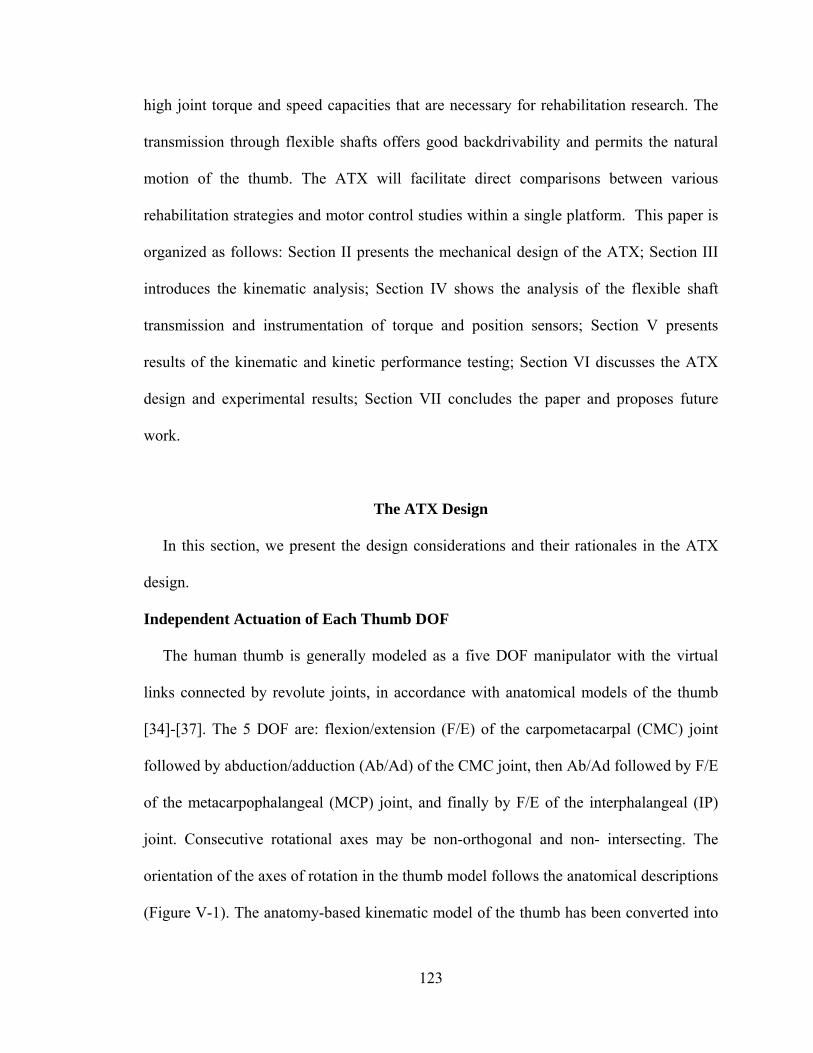
123
high joint torque and speed capacities that are necessary for rehabilitation research. The
transmission through flexible shafts offers good backdrivability and permits the natural
motion of the thumb. The ATX will facilitate direct comparisons between various
rehabilitation strategies and motor control studies within a single platform. This paper is
organized as follows: Section II presents the mechanical design of the ATX; Section III
introduces the kinematic analysis; Section IV shows the analysis of the flexible shaft
transmission and instrumentation of torque and position sensors; Section V presents
results of the kinematic and kinetic performance testing; Section VI discusses the ATX
design and experimental results; Section VII concludes the paper and proposes future
work.
The ATX Design
In this section, we present the design considerations and their rationales in the ATX
design.
Independent Actuation of Each Thumb DOF
The human thumb is generally modeled as a five DOF manipulator with the virtual
links connected by revolute joints, in accordance with anatomical models of the thumb
[34]-[37]. The 5 DOF are: flexion/extension (F/E) of the carpometacarpal (CMC) joint
followed by abduction/adduction (Ab/Ad) of the CMC joint, then Ab/Ad followed by F/E
of the metacarpophalangeal (MCP) joint, and finally by F/E of the interphalangeal (IP)
joint. Consecutive rotational axes may be non-orthogonal and non- intersecting. The
orientation of the axes of rotation in the thumb model follows the anatomical descriptions
(Figure V-1). The anatomy-based kinematic model of the thumb has been converted into
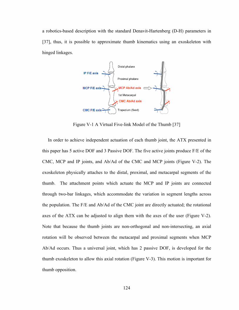
124
a robotics-based description with the standard Denavit-Hartenberg (D-H) parameters in
[37], thus, it is possible to approximate thumb kinematics using an exoskeleton with
hinged linkages.
Figure V-1 A Virtual Five-link Model of the Thumb [37]
In order to achieve independent actuation of each thumb joint, the ATX presented in
this paper has 5 active DOF and 3 Passive DOF. The five active joints produce F/E of the
CMC, MCP and IP joints, and Ab/Ad of the CMC and MCP joints (Figure V-2). The
exoskeleton physically attaches to the distal, proximal, and metacarpal segments of the
thumb. The attachment points which actuate the MCP and IP joints are connected
through two-bar linkages, which accommodate the variation in segment lengths across
the population. The F/E and Ab/Ad of the CMC joint are directly actuated; the rotational
axes of the ATX can be adjusted to align them with the axes of the user (Figure V-2).
Note that because the thumb joints are non-orthogonal and non-intersecting, an axial
rotation will be observed between the metacarpal and proximal segments when MCP
Ab/Ad occurs. Thus a universal joint, which has 2 passive DOF, is developed for the
thumb exoskeleton to allow this axial rotation (Figure V-3). This motion is important for
thumb opposition.
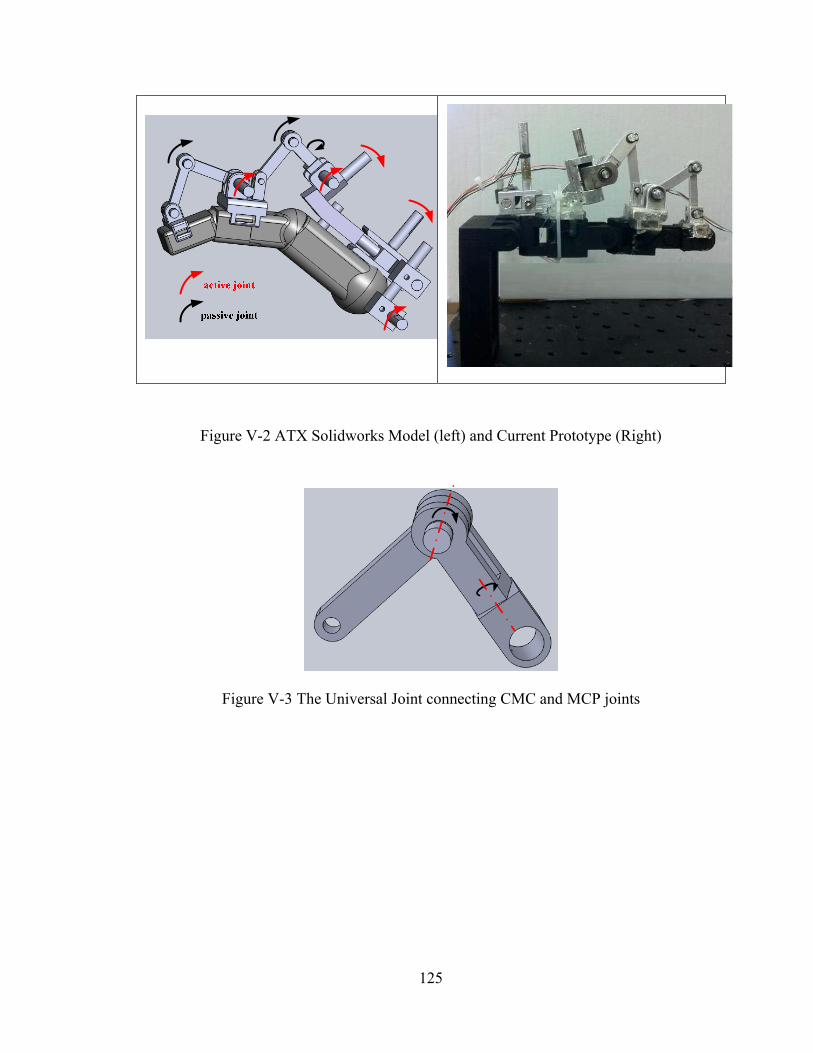
125
Figure V-2 ATX Solidworks Model (left) and Current Prototype (Right)
Figure V-3 The Universal Joint connecting CMC and MCP joints
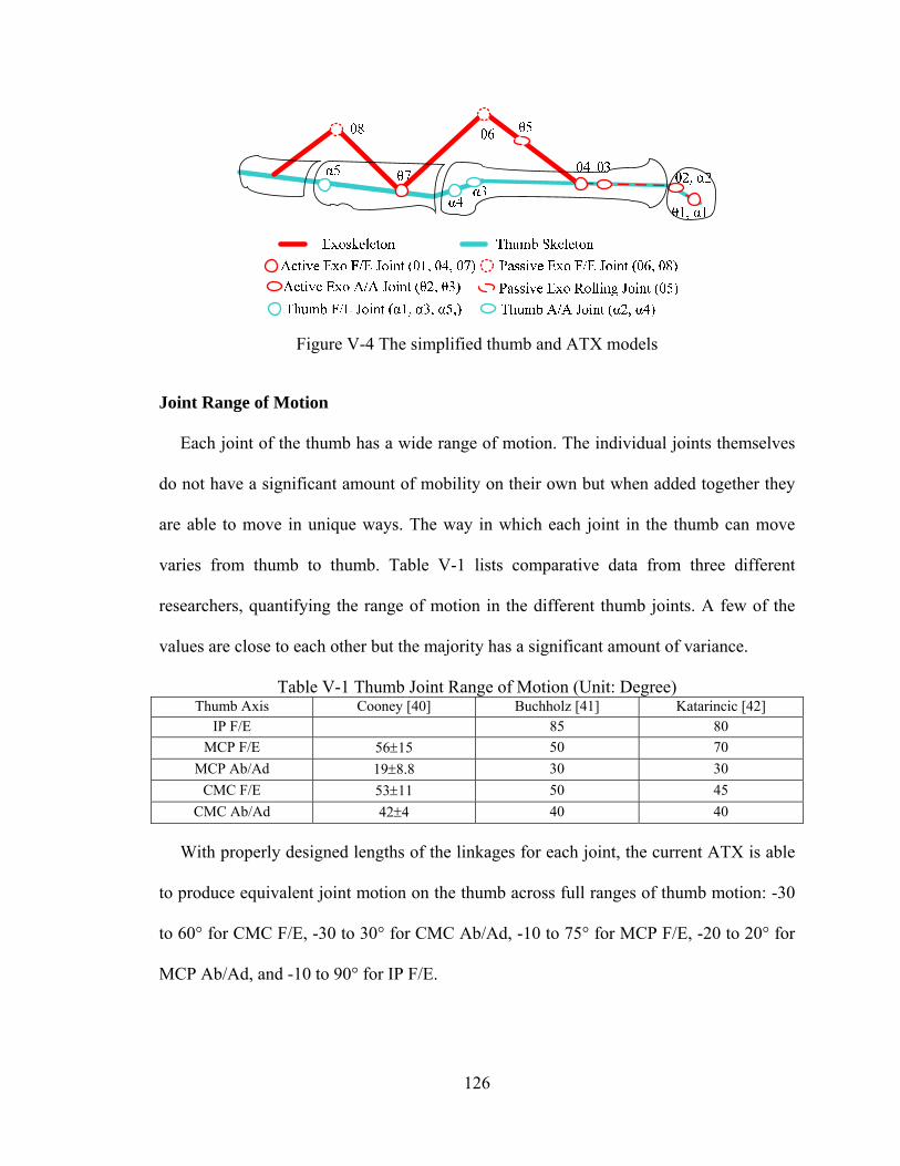
126
Figure V-4 The simplified thumb and ATX models
Joint Range of Motion
Each joint of the thumb has a wide range of motion. The individual joints themselves
do not have a significant amount of mobility on their own but when added together they
are able to move in unique ways. The way in which each joint in the thumb can move
varies from thumb to thumb. Table V-1 lists comparative data from three different
researchers, quantifying the range of motion in the different thumb joints. A few of the
values are close to each other but the majority has a significant amount of variance.
Table V-1 Thumb Joint Range of Motion (Unit: Degree) Thumb Axis Cooney [40] Buchholz [41] Katarincic [42]
IP F/E 85 80
MCP F/E 5615 50 70
MCP Ab/Ad 198.8 30 30
CMC F/E 5311 50 45
CMC Ab/Ad 424 40 40
With properly designed lengths of the linkages for each joint, the current ATX is able
to produce equivalent joint motion on the thumb across full ranges of thumb motion: -30
to 60° for CMC F/E, -30 to 30° for CMC Ab/Ad, -10 to 75° for MCP F/E, -20 to 20° for
MCP Ab/Ad, and -10 to 90° for IP F/E.
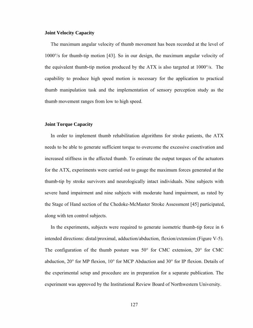
127
Joint Velocity Capacity
The maximum angular velocity of thumb movement has been recorded at the level of
1000°/s for thumb-tip motion [43]. So in our design, the maximum angular velocity of
the equivalent thumb-tip motion produced by the ATX is also targeted at 1000°/s. The
capability to produce high speed motion is necessary for the application to practical
thumb manipulation task and the implementation of sensory perception study as the
thumb movement ranges from low to high speed.
Joint Torque Capacity
In order to implement thumb rehabilitation algorithms for stroke patients, the ATX
needs to be able to generate sufficient torque to overcome the excessive coactivation and
increased stiffness in the affected thumb. To estimate the output torques of the actuators
for the ATX, experiments were carried out to gauge the maximum forces generated at the
thumb-tip by stroke survivors and neurologically intact individuals. Nine subjects with
severe hand impairment and nine subjects with moderate hand impairment, as rated by
the Stage of Hand section of the Chedoke-McMaster Stroke Assessment [45] participated,
along with ten control subjects.
In the experiments, subjects were required to generate isometric thumb-tip force in 6
intended directions: distal/proximal, adduction/abduction, flexion/extension (Figure V-5).
The configuration of the thumb posture was 50° for CMC extension, 20° for CMC
abduction, 20° for MP flexion, 10° for MCP Abduction and 30° for IP flexion. Details of
the experimental setup and procedure are in preparation for a separate publication. The
experiment was approved by the Institutional Review Board of Northwestern University.
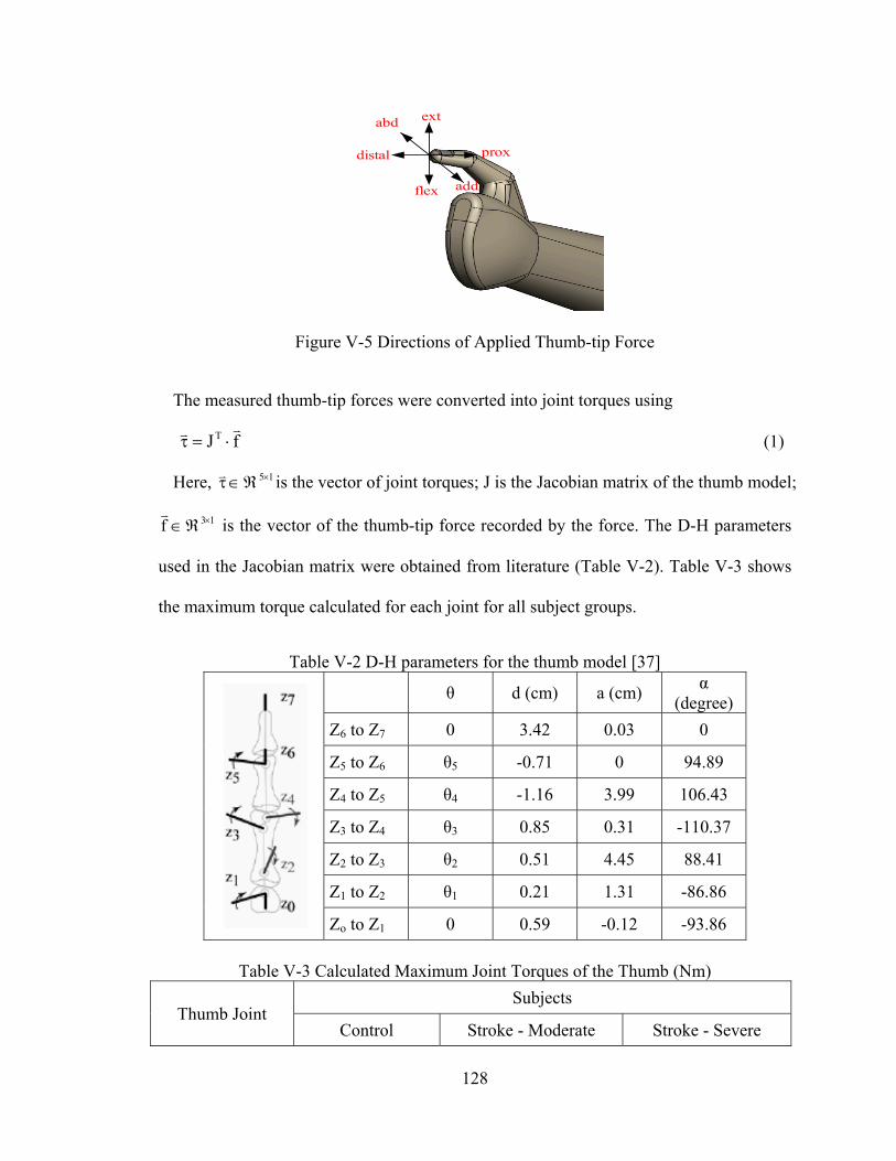
128
distal
flex
extabd
add
prox
Figure V-5 Directions of Applied Thumb-tip Force
The measured thumb-tip forces were converted into joint torques using
fJT (1)
Here, 15 is the vector of joint torques; J is the Jacobian matrix of the thumb model;
13f
is the vector of the thumb-tip force recorded by the force. The D-H parameters
used in the Jacobian matrix were obtained from literature (Table V-2). Table V-3 shows
the maximum torque calculated for each joint for all subject groups.
Table V-2 D-H parameters for the thumb model [37]
θ d (cm) a (cm) α
(degree)
Z6 to Z7 0 3.42 0.03 0
Z5 to Z6 θ5 -0.71 0 94.89
Z4 to Z5 θ4 -1.16 3.99 106.43
Z3 to Z4 θ3 0.85 0.31 -110.37
Z2 to Z3 θ2 0.51 4.45 88.41
Z1 to Z2 θ1 0.21 1.31 -86.86
Zo to Z1 0 0.59 -0.12 -93.86
Table V-3 Calculated Maximum Joint Torques of the Thumb (Nm)
Thumb Joint Subjects
Control Stroke - Moderate Stroke - Severe
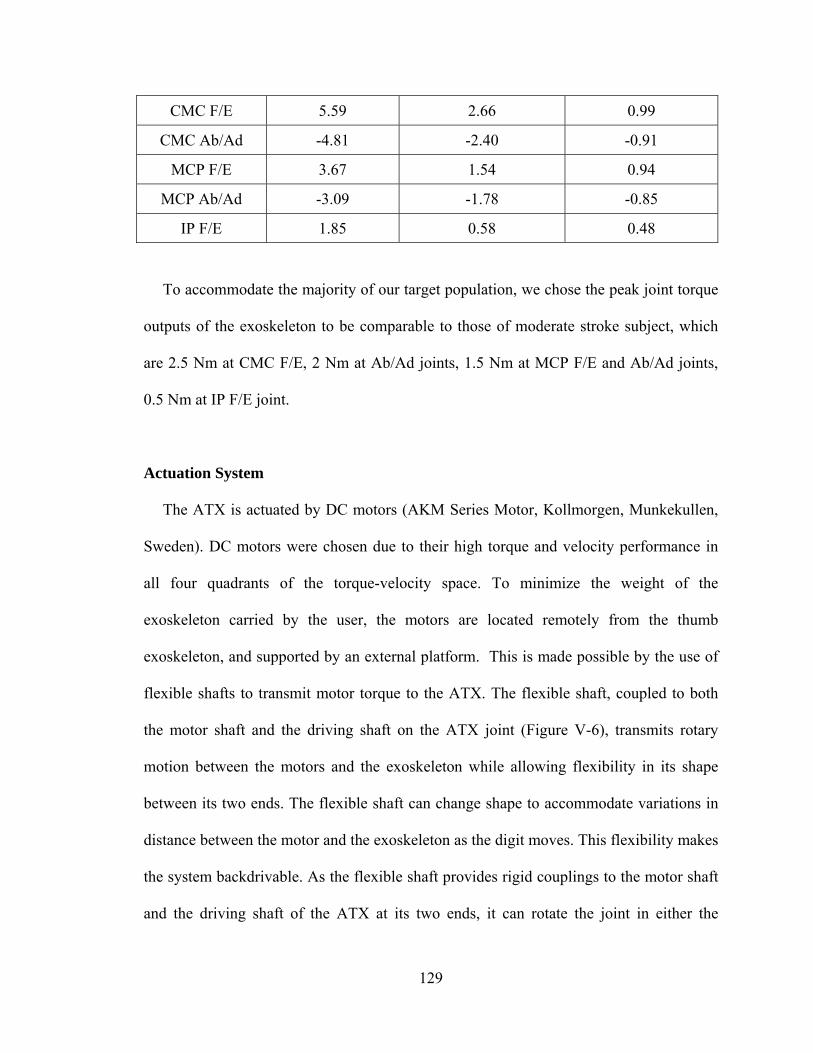
129
CMC F/E 5.59 2.66 0.99
CMC Ab/Ad -4.81 -2.40 -0.91
MCP F/E 3.67 1.54 0.94
MCP Ab/Ad -3.09 -1.78 -0.85
IP F/E 1.85 0.58 0.48
To accommodate the majority of our target population, we chose the peak joint torque
outputs of the exoskeleton to be comparable to those of moderate stroke subject, which
are 2.5 Nm at CMC F/E, 2 Nm at Ab/Ad joints, 1.5 Nm at MCP F/E and Ab/Ad joints,
0.5 Nm at IP F/E joint.
Actuation System
The ATX is actuated by DC motors (AKM Series Motor, Kollmorgen, Munkekullen,
Sweden). DC motors were chosen due to their high torque and velocity performance in
all four quadrants of the torque-velocity space. To minimize the weight of the
exoskeleton carried by the user, the motors are located remotely from the thumb
exoskeleton, and supported by an external platform. This is made possible by the use of
flexible shafts to transmit motor torque to the ATX. The flexible shaft, coupled to both
the motor shaft and the driving shaft on the ATX joint (Figure V-6), transmits rotary
motion between the motors and the exoskeleton while allowing flexibility in its shape
between its two ends. The flexible shaft can change shape to accommodate variations in
distance between the motor and the exoskeleton as the digit moves. This flexibility makes
the system backdrivable. As the flexible shaft provides rigid couplings to the motor shaft
and the driving shaft of the ATX at its two ends, it can rotate the joint in either the
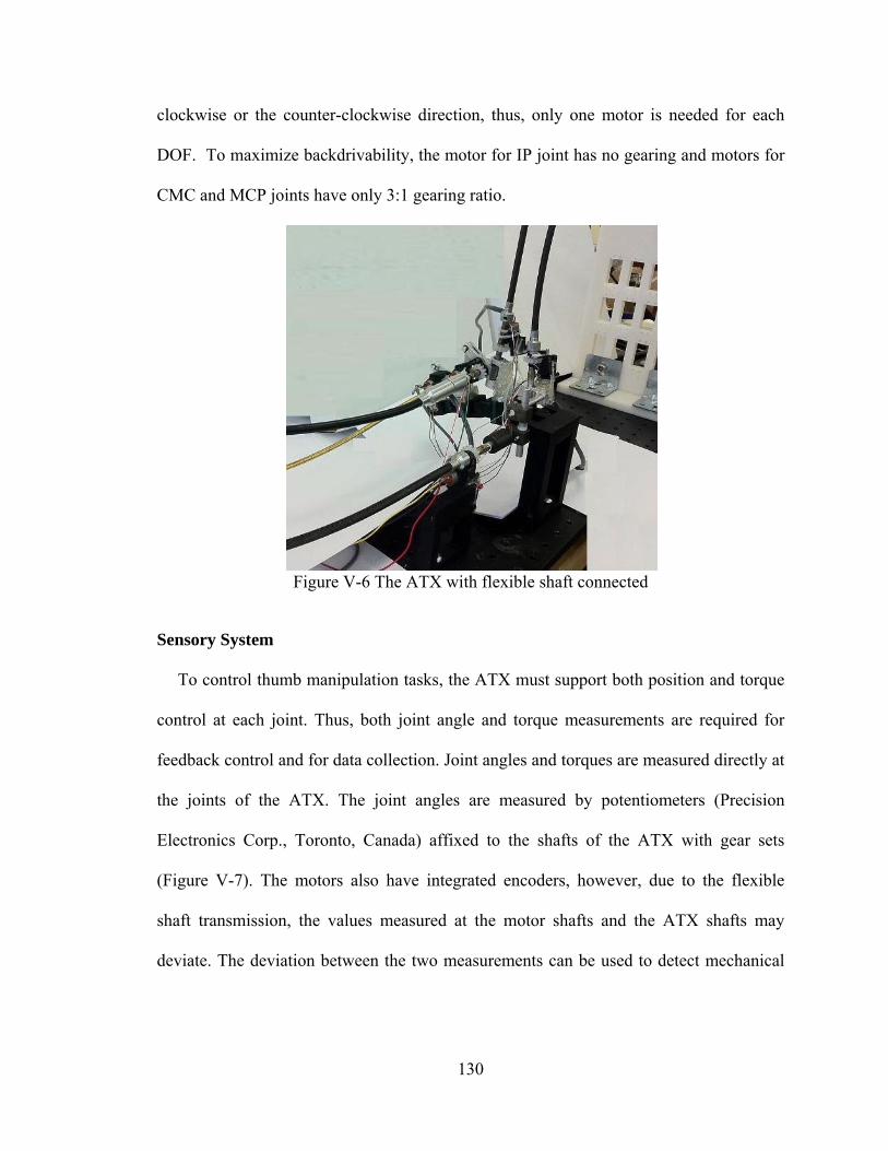
130
clockwise or the counter-clockwise direction, thus, only one motor is needed for each
DOF. To maximize backdrivability, the motor for IP joint has no gearing and motors for
CMC and MCP joints have only 3:1 gearing ratio.
Figure V-6 The ATX with flexible shaft connected
Sensory System
To control thumb manipulation tasks, the ATX must support both position and torque
control at each joint. Thus, both joint angle and torque measurements are required for
feedback control and for data collection. Joint angles and torques are measured directly at
the joints of the ATX. The joint angles are measured by potentiometers (Precision
Electronics Corp., Toronto, Canada) affixed to the shafts of the ATX with gear sets
(Figure V-7). The motors also have integrated encoders, however, due to the flexible
shaft transmission, the values measured at the motor shafts and the ATX shafts may
deviate. The deviation between the two measurements can be used to detect mechanical
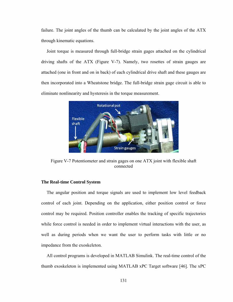
131
failure. The joint angles of the thumb can be calculated by the joint angles of the ATX
through kinematic equations.
Joint torque is measured through full-bridge strain gages attached on the cylindrical
driving shafts of the ATX (Figure V-7). Namely, two rosettes of strain gauges are
attached (one in front and on in back) of each cylindrical drive shaft and these gauges are
then incorporated into a Wheatstone bridge. The full-bridge strain gage circuit is able to
eliminate nonlinearity and hysteresis in the torque measurement.
Figure V-7 Potentiometer and strain gages on one ATX joint with flexible shaft connected
The Real-time Control System
The angular position and torque signals are used to implement low level feedback
control of each joint. Depending on the application, either position control or force
control may be required. Position controller enables the tracking of specific trajectories
while force control is needed in order to implement virtual interactions with the user, as
well as during periods when we want the user to perform tasks with little or no
impedance from the exoskeleton.
All control programs is developed in MATLAB Simulink. The real-time control of the
thumb exoskeleton is implemented using MATLAB xPC Target software [46]. The xPC
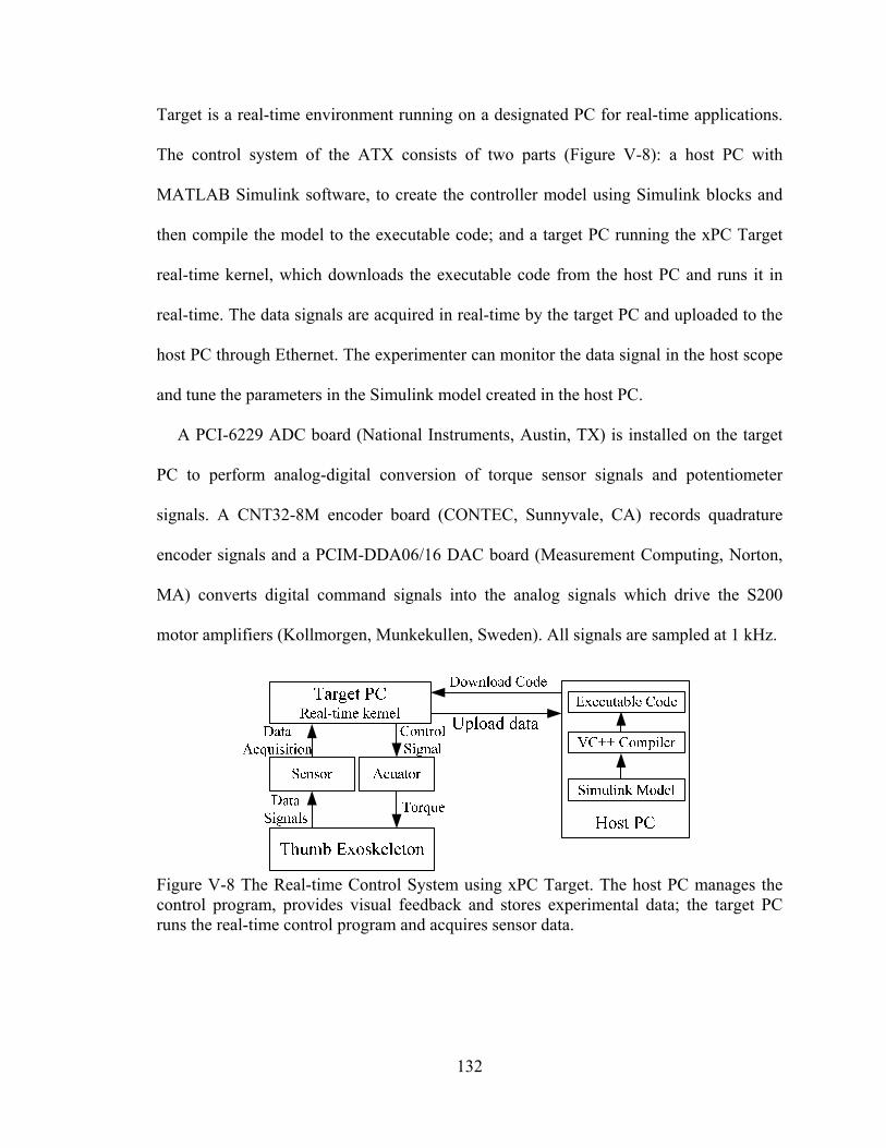
132
Target is a real-time environment running on a designated PC for real-time applications.
The control system of the ATX consists of two parts (Figure V-8): a host PC with
MATLAB Simulink software, to create the controller model using Simulink blocks and
then compile the model to the executable code; and a target PC running the xPC Target
real-time kernel, which downloads the executable code from the host PC and runs it in
real-time. The data signals are acquired in real-time by the target PC and uploaded to the
host PC through Ethernet. The experimenter can monitor the data signal in the host scope
and tune the parameters in the Simulink model created in the host PC.
A PCI-6229 ADC board (National Instruments, Austin, TX) is installed on the target
PC to perform analog-digital conversion of torque sensor signals and potentiometer
signals. A CNT32-8M encoder board (CONTEC, Sunnyvale, CA) records quadrature
encoder signals and a PCIM-DDA06/16 DAC board (Measurement Computing, Norton,
MA) converts digital command signals into the analog signals which drive the S200
motor amplifiers (Kollmorgen, Munkekullen, Sweden). All signals are sampled at 1 kHz.
Figure V-8 The Real-time Control System using xPC Target. The host PC manages the control program, provides visual feedback and stores experimental data; the target PC runs the real-time control program and acquires sensor data.
133
Safety and Limitations
A number of safety mechanisms are implemented to ensure safe interaction with the
individual’s hand. The lever linkages restrict the angular position of each joint of the
ATX in the acceptable range. An emergency kill switch is provided to immediately
disable all motors. Software monitoring of both joint position and motor torque, will
continuously check to see if specified limits are exceeded and will immediately disable
the system should this occur.
In our design, individually sized motors and flexible shafts are used for the different
joints. In this manner, peak motor torque can be better matched to peak voluntary subject
torque and thus the potential for excessive torque is minimized.
Kinematic Analysis
In this section, we analyze the kinematics of the coupled system of the ATX model
and the thumb model.
The thumb and the ATX can be modeled as chains of rigid links as shown in Figure
V-4. Both the thumb and the ATX models have individual kinematic redundancy for the
3 DOF of their tip locations, as the thumb model has 5 DOF and the ATX has 5 active
DOF and 3 passive DOF in the joint-space (orientation of the end-effectors is not
considered for the current application). Thus, for a given task-space trajectory, there will
be an infinite number of possible joint-space trajectories for either the thumb or the ATX
model. One concern of this redundant system is whether a unique mapping can be
established between the joint-space trajectories of the thumb and the ATX models.

134
The task-space trajectories of the thumb model and the ATX model are represented by
the joint-space trajectories using forward kinematics:
),(f)(fX),(fX paexoexoexothumbthumb
(2)
where thumbX
, exoX
3X1 are the thumb-tip position and the end-effector position of
the ATX model in the Cartesian space, respectively. 5X1 is the vector of the joint
angles of the thumb model; a 5X1, a=1, 2, 3, 4 and 5, and p
3X1, p=6, 7 and 8,
are the vectors of the active and the passive joint angles of the ATX model, respectively.
The position of the attachment points can be written as,
),,,,,,,(FX
),,,,,(FX
,FX
8765432133C
65432122C
2111C
(3)
and,
),,,,(GX
),,,(GX
,GX
5432133C
432122C
2111C
(4)
where 1F
, 1G
2X1, 32 F,F
, 32 G,G
3X1 are the functions of the positions at
constraint points.
Since the functions 321pa F;F;F),(F
and 321 G;G;G)(G
represent the
positions of the same set of constraint points,
0 GF),,(H pa
, H 8X1. (5)
It is unrealistic to solve Equation (6) to obtain the joint angle of the thumb from the
measured joint angle of the ATX directly as those equations are highly nonlinear. Thus,
Equation (6) is differentiated once to obtain the mapping at the velocity level,
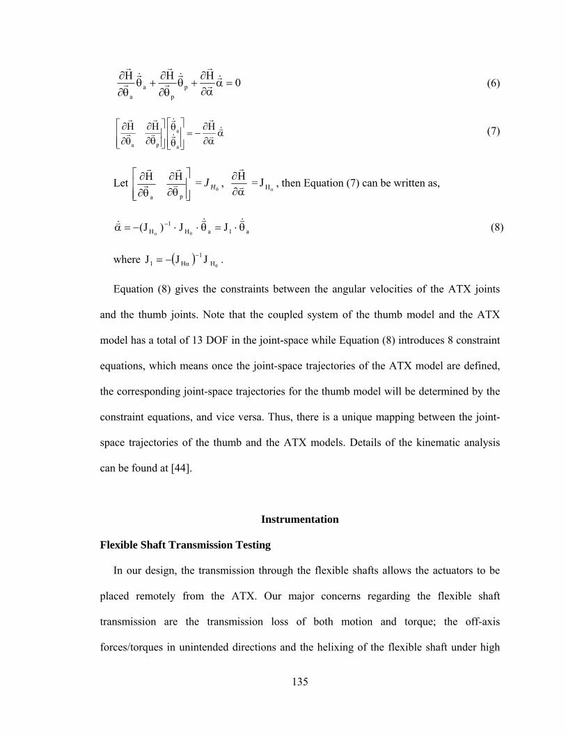
135
0HHH
p
p
a
a
(6)
HHH
a
a
pa
(7)
Let
pa
HH
=HJ ,
H
=HJ , then Equation (7) can be written as,
a1aH1
H JJ)J(
(8)
where
H
1H1 JJJ .
Equation (8) gives the constraints between the angular velocities of the ATX joints
and the thumb joints. Note that the coupled system of the thumb model and the ATX
model has a total of 13 DOF in the joint-space while Equation (8) introduces 8 constraint
equations, which means once the joint-space trajectories of the ATX model are defined,
the corresponding joint-space trajectories for the thumb model will be determined by the
constraint equations, and vice versa. Thus, there is a unique mapping between the joint-
space trajectories of the thumb and the ATX models. Details of the kinematic analysis
can be found at [44].
Instrumentation
Flexible Shaft Transmission Testing
In our design, the transmission through the flexible shafts allows the actuators to be
placed remotely from the ATX. Our major concerns regarding the flexible shaft
transmission are the transmission loss of both motion and torque; the off-axis
forces/torques in unintended directions and the helixing of the flexible shaft under high
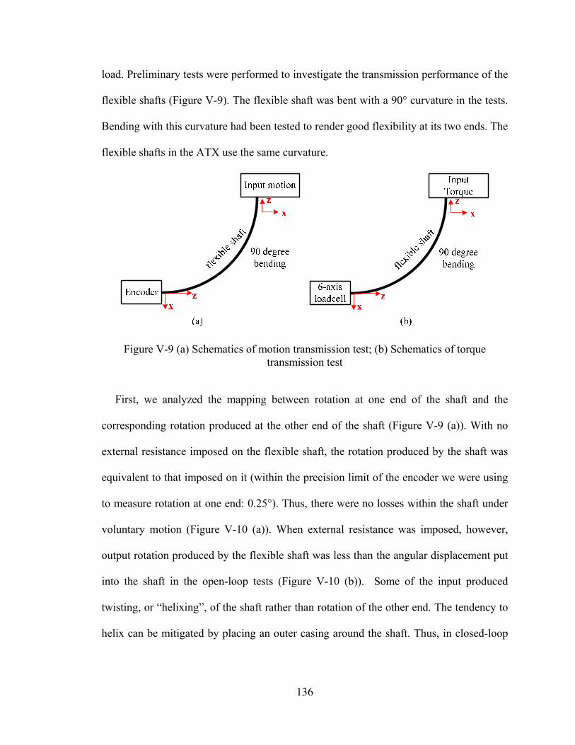
136
load. Preliminary tests were performed to investigate the transmission performance of the
flexible shafts (Figure V-9). The flexible shaft was bent with a 90° curvature in the tests.
Bending with this curvature had been tested to render good flexibility at its two ends. The
flexible shafts in the ATX use the same curvature.
Figure V-9 (a) Schematics of motion transmission test; (b) Schematics of torque transmission test
First, we analyzed the mapping between rotation at one end of the shaft and the
corresponding rotation produced at the other end of the shaft (Figure V-9 (a)). With no
external resistance imposed on the flexible shaft, the rotation produced by the shaft was
equivalent to that imposed on it (within the precision limit of the encoder we were using
to measure rotation at one end: 0.25°). Thus, there were no losses within the shaft under
voluntary motion (Figure V-10 (a)). When external resistance was imposed, however,
output rotation produced by the flexible shaft was less than the angular displacement put
into the shaft in the open-loop tests (Figure V-10 (b)). Some of the input produced
twisting, or “helixing”, of the shaft rather than rotation of the other end. The tendency to
helix can be mitigated by placing an outer casing around the shaft. Thus, in closed-loop

137
control under high torque, the angular position measurements have to be measure directly
at the exoskeleton end rather than the motor end.
Figure V-10 Kinematic transmission through the flexible shaft: (a) motion transmission under no torque load; (b) motion transmission under torque.
Torque transmission performance through the flexible shaft was examined as well
(Figure V-9 (b)). Figure V-11 shows the torque transmission performance of the flexible
shaft. Output torque at the distal end of the shaft stayed within 10% error of the input
torque imposed at the proximal end of the shaft for input torques up to 1 Nm. Shaft
efficiency is dependent upon the shape of the shaft. With a straighter shaft, as opposed to
the curved posture we used in our tests, correspondence between input and output torque
improves. Thus, in closed-loop control, torque needs to be measured directly at the
driving shaft for the actuated joint of the ATX.
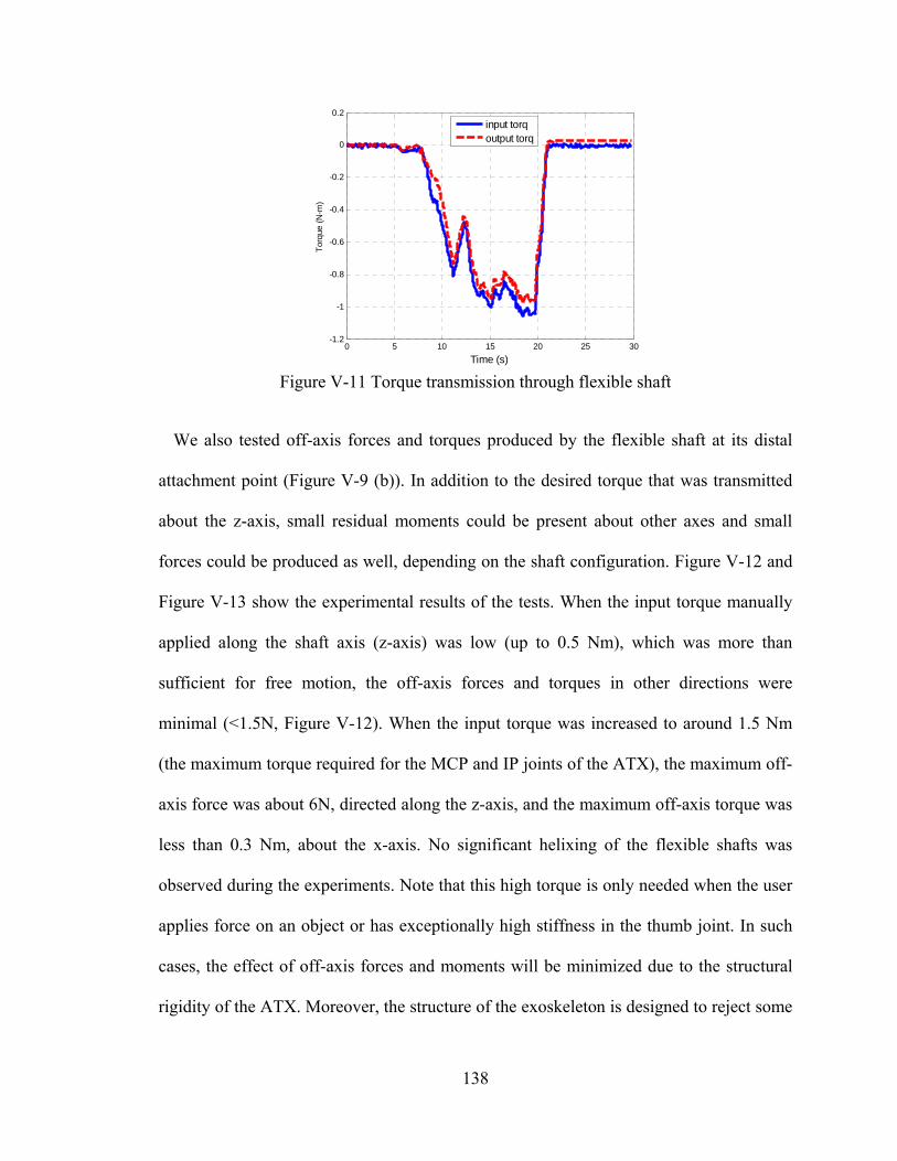
138
Figure V-11 Torque transmission through flexible shaft
We also tested off-axis forces and torques produced by the flexible shaft at its distal
attachment point (Figure V-9 (b)). In addition to the desired torque that was transmitted
about the z-axis, small residual moments could be present about other axes and small
forces could be produced as well, depending on the shaft configuration. Figure V-12 and
Figure V-13 show the experimental results of the tests. When the input torque manually
applied along the shaft axis (z-axis) was low (up to 0.5 Nm), which was more than
sufficient for free motion, the off-axis forces and torques in other directions were
minimal (<1.5N, Figure V-12). When the input torque was increased to around 1.5 Nm
(the maximum torque required for the MCP and IP joints of the ATX), the maximum off-
axis force was about 6N, directed along the z-axis, and the maximum off-axis torque was
less than 0.3 Nm, about the x-axis. No significant helixing of the flexible shafts was
observed during the experiments. Note that this high torque is only needed when the user
applies force on an object or has exceptionally high stiffness in the thumb joint. In such
cases, the effect of off-axis forces and moments will be minimized due to the structural
rigidity of the ATX. Moreover, the structure of the exoskeleton is designed to reject some
0 5 10 15 20 25 30-1.2
-1
-0.8
-0.6
-0.4
-0.2
0
0.2
Time (s)
Tor
que
(N-m
)
input torqoutput torq
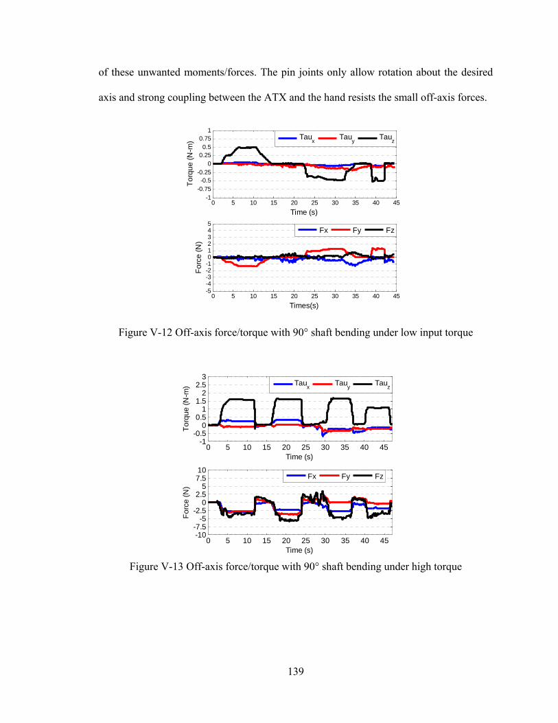
139
of these unwanted moments/forces. The pin joints only allow rotation about the desired
axis and strong coupling between the ATX and the hand resists the small off-axis forces.
Figure V-12 Off-axis force/torque with 90° shaft bending under low input torque
Figure V-13 Off-axis force/torque with 90° shaft bending under high torque
0 5 10 15 20 25 30 35 40 45-5-4-3-2-1012345
Times(s)
Fo
rce
(N
)
0 5 10 15 20 25 30 35 40 45-1
-0.75-0.5
-0.250
0.250.5
0.751
Time (s)
To
rqu
e (
N-m
)
Tau
xTau
yTau
z
Fx Fy Fz
0 5 10 15 20 25 30 35 40 45-10-7.5
-5-2.5
02.5
57.510
Time (s)
Fo
rce
(N
)
0 5 10 15 20 25 30 35 40 45-1
-0.50
0.51
1.52
2.53
Time (s)
To
rqu
e (
N-m
)
Fx Fy Fz
Taux Tau
yTau
z
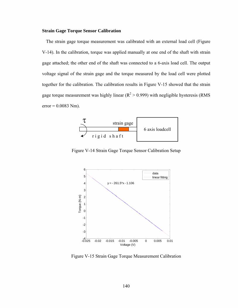
140
Strain Gage Torque Sensor Calibration
The strain gage torque measurement was calibrated with an external load cell (Figure
V-14). In the calibration, torque was applied manually at one end of the shaft with strain
gage attached; the other end of the shaft was connected to a 6-axis load cell. The output
voltage signal of the strain gage and the torque measured by the load cell were plotted
together for the calibration. The calibration results in Figure V-15 showed that the strain
gage torque measurement was highly linear (R2 > 0.999) with negligible hysteresis (RMS
error = 0.0083 Nm).
6 axis loadcellstrain gage
r i g i d s h a f t
Figure V-14 Strain Gage Torque Sensor Calibration Setup
Figure V-15 Strain Gage Torque Measurement Calibration
-0.025 -0.02 -0.015 -0.01 -0.005 0 0.005 0.01-4
-3
-2
-1
0
1
2
3
4
5
6
Voltage (V)
To
rqu
e (
N-m
)
y = - 261.5*x - 1.106
datalinear fitting
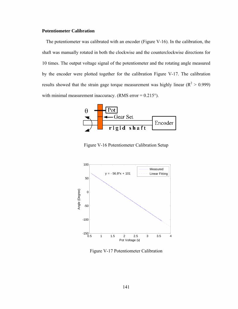
141
Potentiometer Calibration
The potentiometer was calibrated with an encoder (Figure V-16). In the calibration, the
shaft was manually rotated in both the clockwise and the counterclockwise directions for
10 times. The output voltage signal of the potentiometer and the rotating angle measured
by the encoder were plotted together for the calibration Figure V-17. The calibration
results showed that the strain gage torque measurement was highly linear (R2 > 0.999)
with minimal measurement inaccuracy. (RMS error = 0.215°).
Figure V-16 Potentiometer Calibration Setup
Figure V-17 Potentiometer Calibration
0.5 1 1.5 2 2.5 3 3.5 4-150
-100
-50
0
50
100
Pot Voltage (v)
Ang
le (
Deg
ree)
y = - 56.8*x + 101
Measured
Linear Fitting
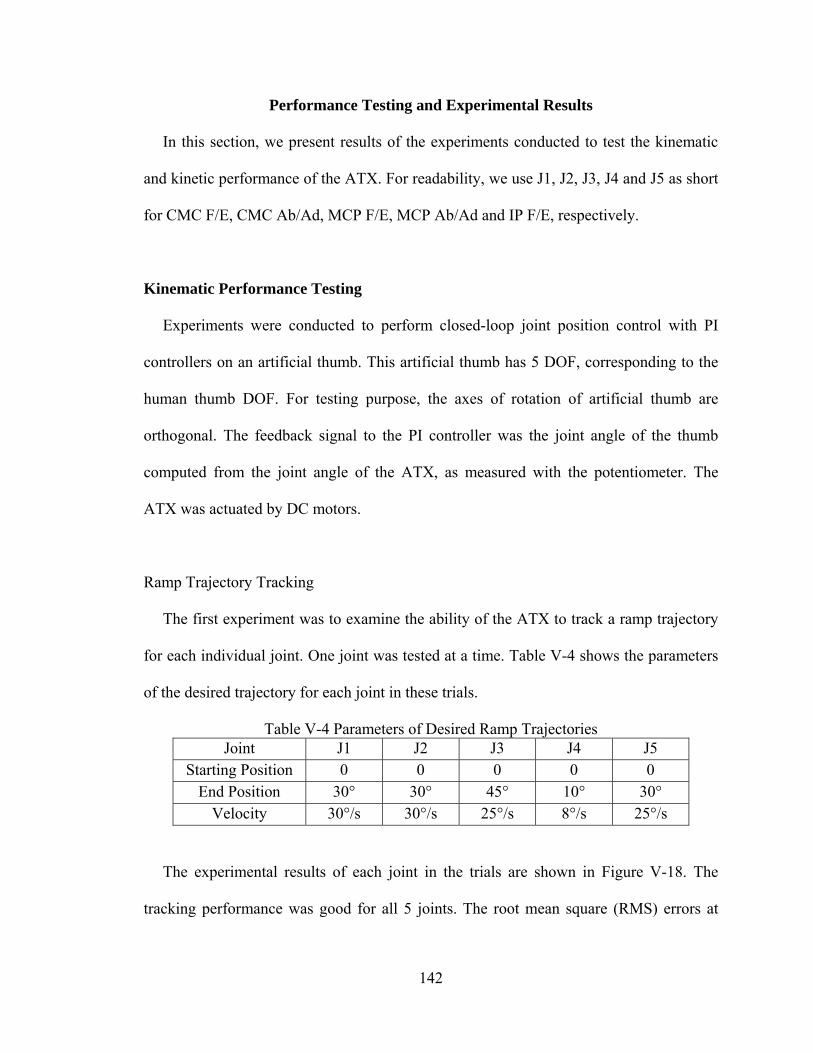
142
Performance Testing and Experimental Results
In this section, we present results of the experiments conducted to test the kinematic
and kinetic performance of the ATX. For readability, we use J1, J2, J3, J4 and J5 as short
for CMC F/E, CMC Ab/Ad, MCP F/E, MCP Ab/Ad and IP F/E, respectively.
Kinematic Performance Testing
Experiments were conducted to perform closed-loop joint position control with PI
controllers on an artificial thumb. This artificial thumb has 5 DOF, corresponding to the
human thumb DOF. For testing purpose, the axes of rotation of artificial thumb are
orthogonal. The feedback signal to the PI controller was the joint angle of the thumb
computed from the joint angle of the ATX, as measured with the potentiometer. The
ATX was actuated by DC motors.
Ramp Trajectory Tracking
The first experiment was to examine the ability of the ATX to track a ramp trajectory
for each individual joint. One joint was tested at a time. Table V-4 shows the parameters
of the desired trajectory for each joint in these trials.
Table V-4 Parameters of Desired Ramp Trajectories Joint J1 J2 J3 J4 J5
Starting Position 0 0 0 0 0 End Position 30° 30° 45° 10° 30°
Velocity 30°/s 30°/s 25°/s 8°/s 25°/s
The experimental results of each joint in the trials are shown in Figure V-18. The
tracking performance was good for all 5 joints. The root mean square (RMS) errors at
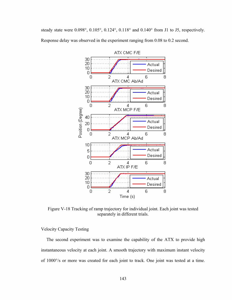
143
steady state were 0.098°, 0.105°, 0.124°, 0.118° and 0.140° from J1 to J5, respectively.
Response delay was observed in the experiment ranging from 0.08 to 0.2 second.
Figure V-18 Tracking of ramp trajectory for individual joint. Each joint was tested separately in different trials.
Velocity Capacity Testing
The second experiment was to examine the capability of the ATX to provide high
instantaneous velocity at each joint. A smooth trajectory with maximum instant velocity
of 1000°/s or more was created for each joint to track. One joint was tested at a time.
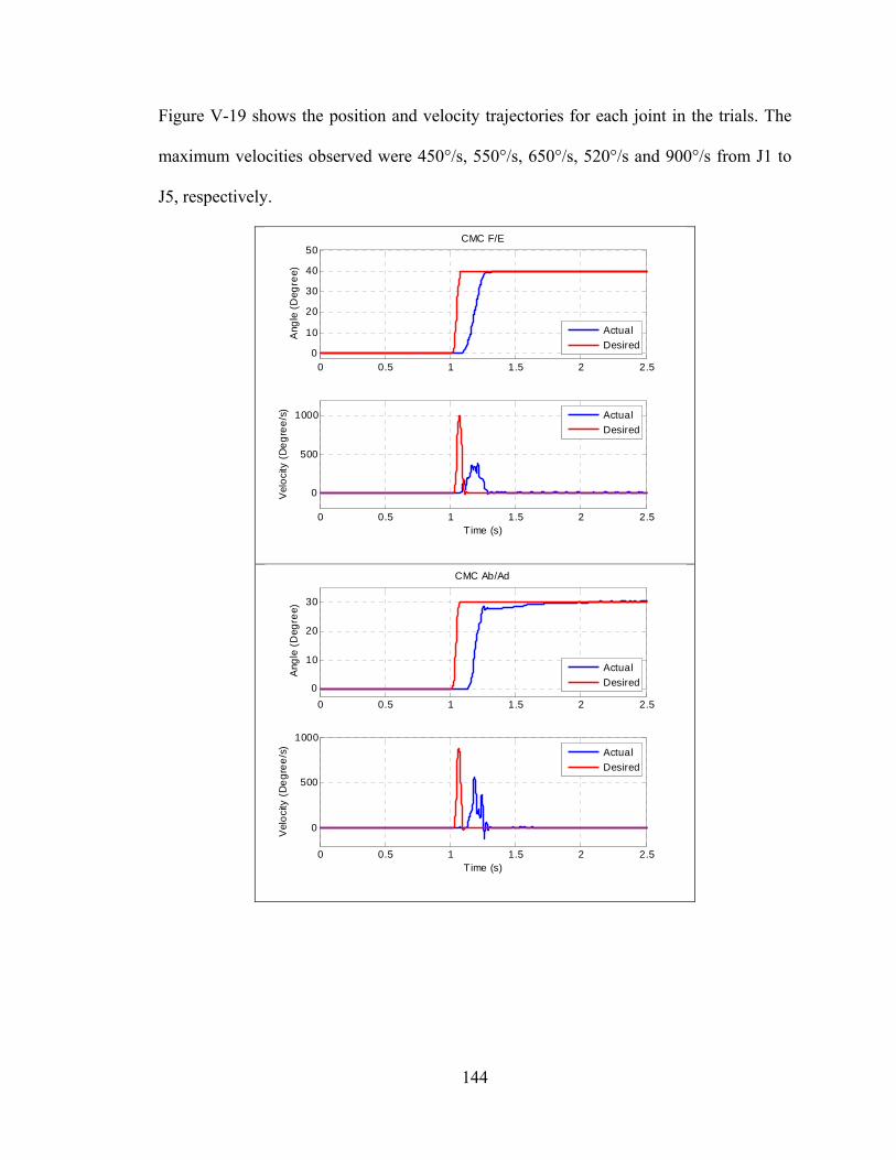
144
Figure V-19 shows the position and velocity trajectories for each joint in the trials. The
maximum velocities observed were 450°/s, 550°/s, 650°/s, 520°/s and 900°/s from J1 to
J5, respectively.
0 0.5 1 1.5 2 2.50
10
20
30
40
50CMC F/E
Ang
le (
Deg
ree)
0 0.5 1 1.5 2 2.5
0
500
1000
Time (s)
Vel
oci
ty (
De
gre
e/s
)
Actual
Desired
Actual
Desired
0 0.5 1 1.5 2 2.5
0
10
20
30
CMC Ab/Ad
Ang
le (
Deg
ree)
0 0.5 1 1.5 2 2.5
0
500
1000
Time (s)
Vel
oci
ty (
De
gre
e/s
)
Actual
Desired
Actual
Desired
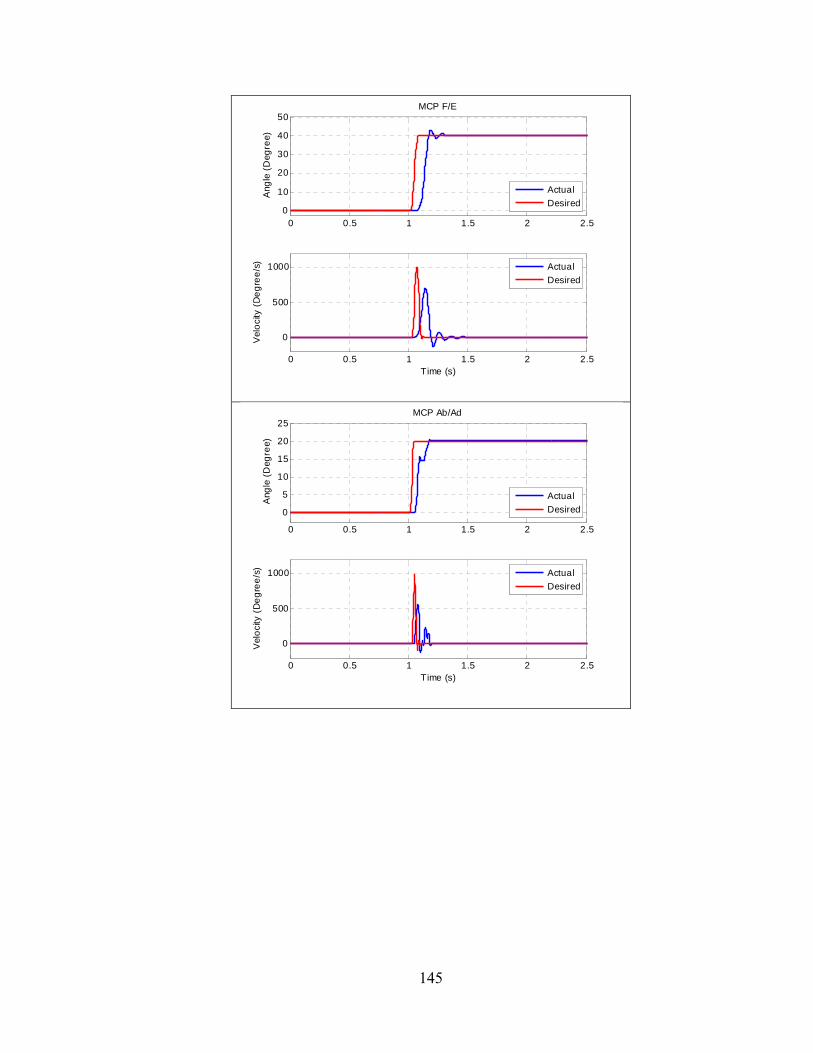
145
0 0.5 1 1.5 2 2.50
10
20
30
40
50MCP F/E
Ang
le (
Deg
ree)
0 0.5 1 1.5 2 2.5
0
500
1000
Time (s)
Vel
oci
ty (
De
gre
e/s
)
Actual
Desired
Actual
Desired
0 0.5 1 1.5 2 2.5
0
5
10
15
20
25MCP Ab/Ad
Ang
le (
Deg
ree)
0 0.5 1 1.5 2 2.5
0
500
1000
Time (s)
Vel
oci
ty (
De
gre
e/s
)
Actual
Desired
Actual
Desired
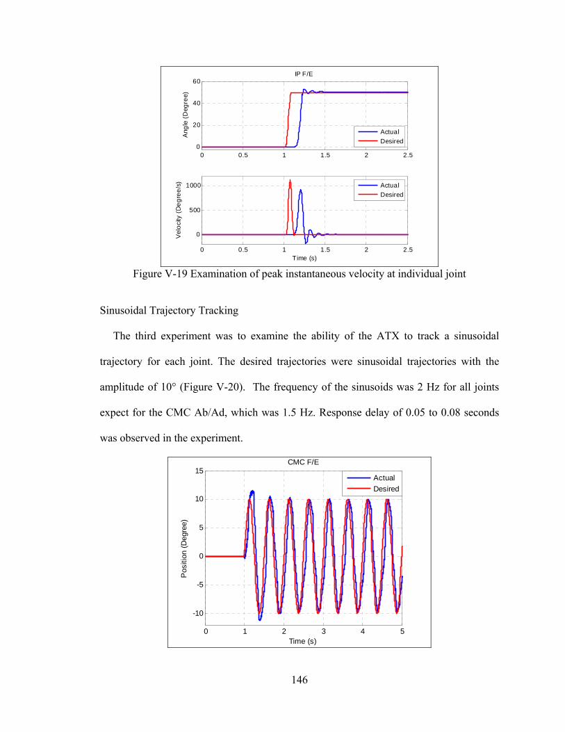
146
Figure V-19 Examination of peak instantaneous velocity at individual joint
Sinusoidal Trajectory Tracking
The third experiment was to examine the ability of the ATX to track a sinusoidal
trajectory for each joint. The desired trajectories were sinusoidal trajectories with the
amplitude of 10° (Figure V-20). The frequency of the sinusoids was 2 Hz for all joints
expect for the CMC Ab/Ad, which was 1.5 Hz. Response delay of 0.05 to 0.08 seconds
was observed in the experiment.
0 0.5 1 1.5 2 2.50
20
40
60IP F/E
Ang
le (
Deg
ree)
0 0.5 1 1.5 2 2.5
0
500
1000
Time (s)
Vel
oci
ty (
De
gre
e/s
)
Actual
Desired
Actual
Desired
0 1 2 3 4 5
-10
-5
0
5
10
15CMC F/E
Time (s)
Pos
ition
(D
egre
e)
Actual
Desired
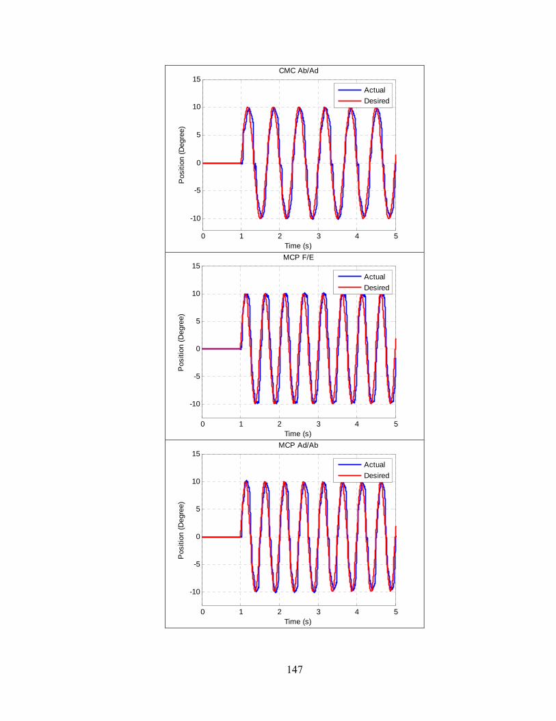
147
0 1 2 3 4 5
-10
-5
0
5
10
15CMC Ab/Ad
Time (s)
Pos
ition
(D
egre
e)
Actual
Desired
0 1 2 3 4 5
-10
-5
0
5
10
15MCP F/E
Time (s)
Pos
ition
(D
egre
e)
Actual
Desired
0 1 2 3 4 5
-10
-5
0
5
10
15MCP Ad/Ab
Time (s)
Pos
ition
(D
egre
e)
Actual
Desired
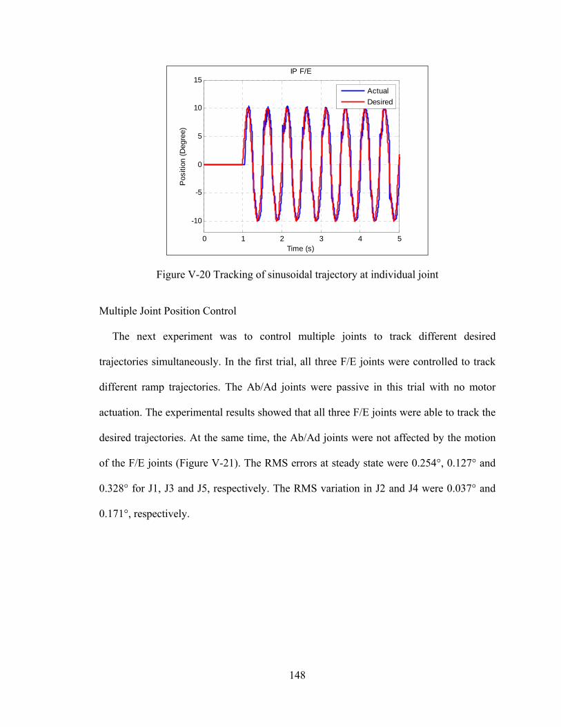
148
Figure V-20 Tracking of sinusoidal trajectory at individual joint
Multiple Joint Position Control
The next experiment was to control multiple joints to track different desired
trajectories simultaneously. In the first trial, all three F/E joints were controlled to track
different ramp trajectories. The Ab/Ad joints were passive in this trial with no motor
actuation. The experimental results showed that all three F/E joints were able to track the
desired trajectories. At the same time, the Ab/Ad joints were not affected by the motion
of the F/E joints (Figure V-21). The RMS errors at steady state were 0.254°, 0.127° and
0.328° for J1, J3 and J5, respectively. The RMS variation in J2 and J4 were 0.037° and
0.171°, respectively.
0 1 2 3 4 5
-10
-5
0
5
10
15IP F/E
Time (s)
Pos
ition
(D
egre
e)
Actual
Desired
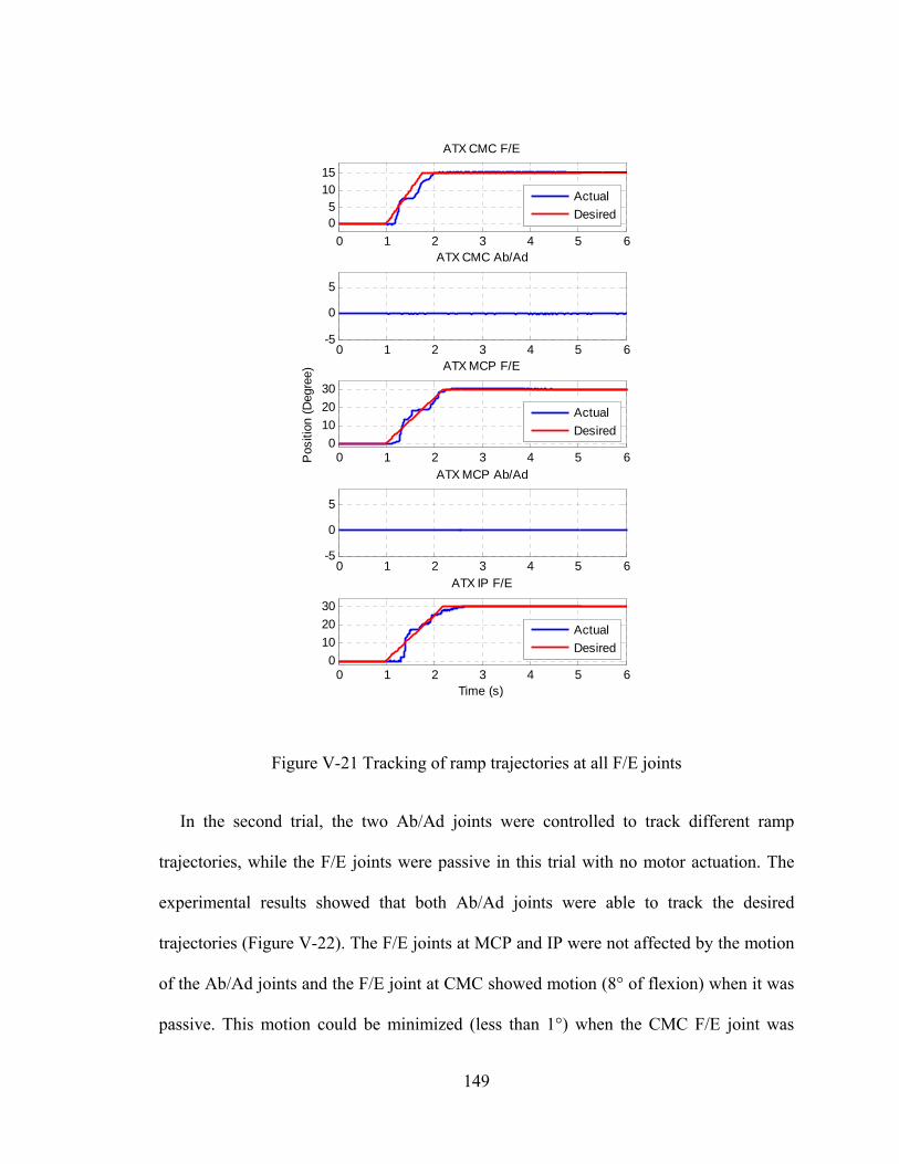
149
Figure V-21 Tracking of ramp trajectories at all F/E joints
In the second trial, the two Ab/Ad joints were controlled to track different ramp
trajectories, while the F/E joints were passive in this trial with no motor actuation. The
experimental results showed that both Ab/Ad joints were able to track the desired
trajectories (Figure V-22). The F/E joints at MCP and IP were not affected by the motion
of the Ab/Ad joints and the F/E joint at CMC showed motion (8° of flexion) when it was
passive. This motion could be minimized (less than 1°) when the CMC F/E joint was
0 1 2 3 4 5 60
10
20
30
ATX IP F/E
Time (s)
Actual
Desired
0 1 2 3 4 5 60
10
20
30
ATX MCP F/E
Pos
ition
(D
egre
e)
Actual
Desired
0 1 2 3 4 5 6-5
0
5
ATX MCP Ab/Ad
0 1 2 3 4 5 6-5
0
5
ATX CMC Ab/Ad0 1 2 3 4 5 6
05
1015
ATX CMC F/E
Actual
Desired
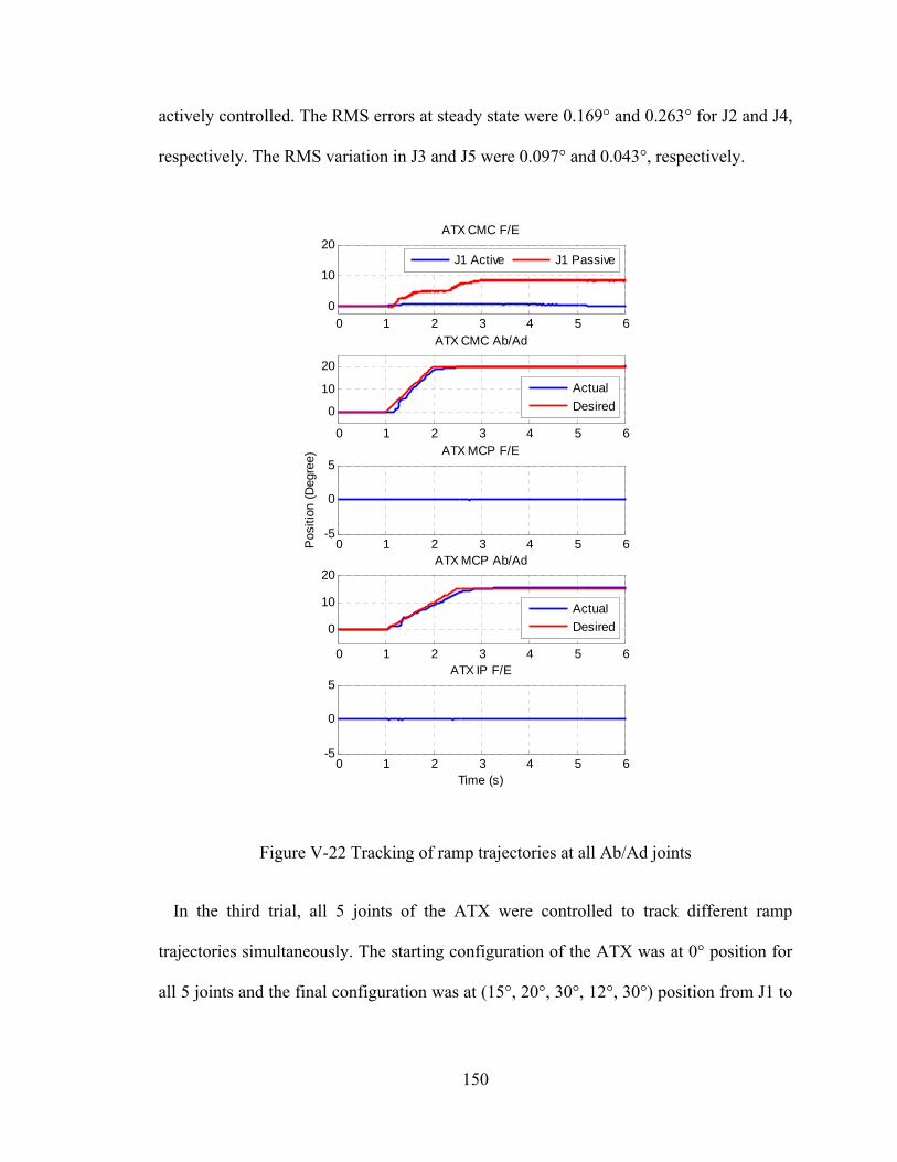
150
actively controlled. The RMS errors at steady state were 0.169° and 0.263° for J2 and J4,
respectively. The RMS variation in J3 and J5 were 0.097° and 0.043°, respectively.
Figure V-22 Tracking of ramp trajectories at all Ab/Ad joints
In the third trial, all 5 joints of the ATX were controlled to track different ramp
trajectories simultaneously. The starting configuration of the ATX was at 0° position for
all 5 joints and the final configuration was at (15°, 20°, 30°, 12°, 30°) position from J1 to
0 1 2 3 4 5 6-5
0
5ATX IP F/E
Time (s)
0 1 2 3 4 5 6-5
0
5ATX MCP F/E
Pos
ition
(D
egre
e)
0 1 2 3 4 5 6
0
10
20ATX MCP Ab/Ad
Actual
Desired
0 1 2 3 4 5 6
0
10
20
ATX CMC Ab/Ad
Actual
Desired
0 1 2 3 4 5 60
10
20ATX CMC F/E
J1 Active J1 Passive
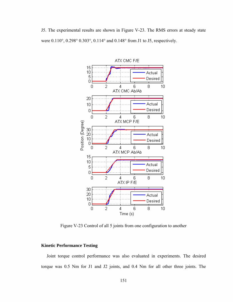
151
J5. The experimental results are shown in Figure V-23. The RMS errors at steady state
were 0.110°, 0.298° 0.303°, 0.114° and 0.148° from J1 to J5, respectively.
Figure V-23 Control of all 5 joints from one configuration to another
Kinetic Performance Testing
Joint torque control performance was also evaluated in experiments. The desired
torque was 0.5 Nm for J1 and J2 joints, and 0.4 Nm for all other three joints. The
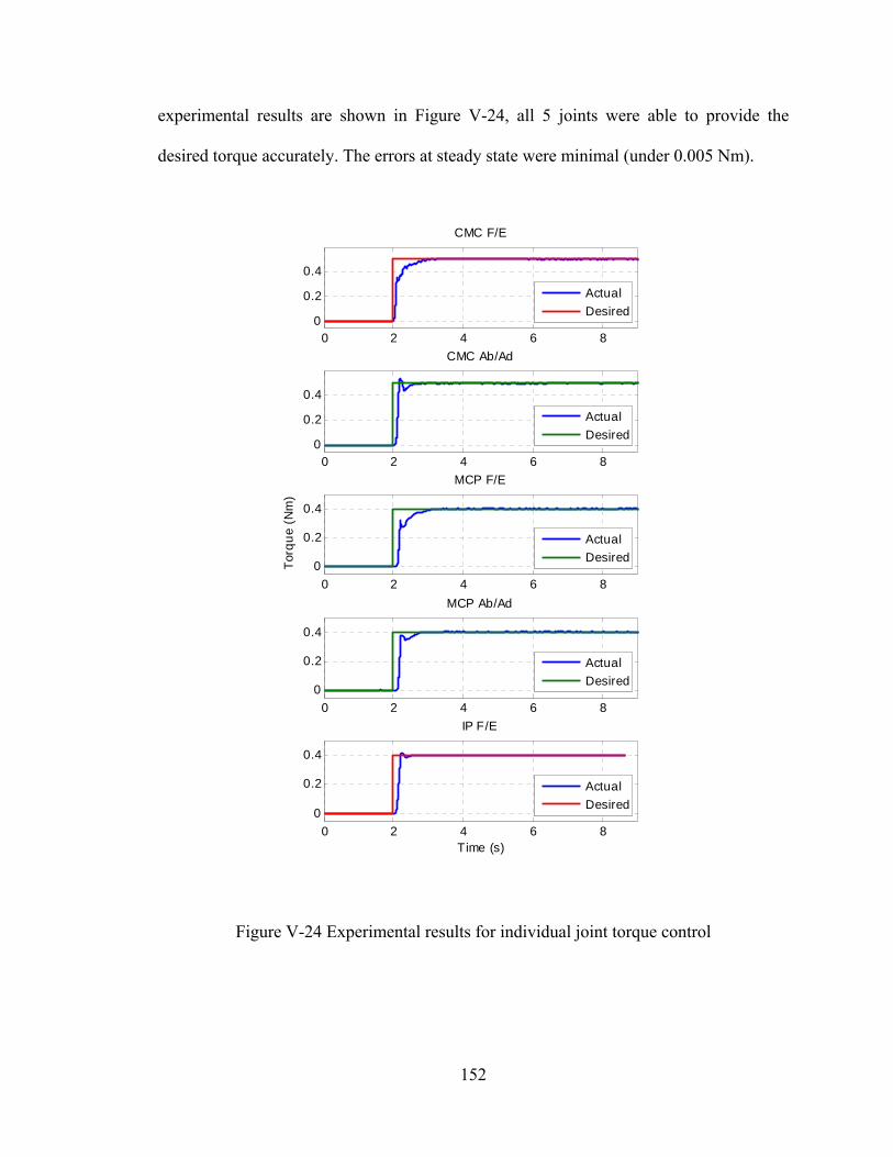
152
experimental results are shown in Figure V-24, all 5 joints were able to provide the
desired torque accurately. The errors at steady state were minimal (under 0.005 Nm).
Figure V-24 Experimental results for individual joint torque control
0 2 4 6 8
0
0.2
0.4
Time (s)
IP F/E
0 2 4 6 80
0.2
0.4
CMC F/E
0 2 4 6 8
0
0.2
0.4
Tor
qu
e (N
m)
MCP F/E
0 2 4 6 8
0
0.2
0.4
MCP Ab/Ad
0 2 4 6 80
0.2
0.4
CMC Ab/Ad
Actual
Desired
Actual
Desired
Actual
Desired
Actual
Desired
Actual
Desired
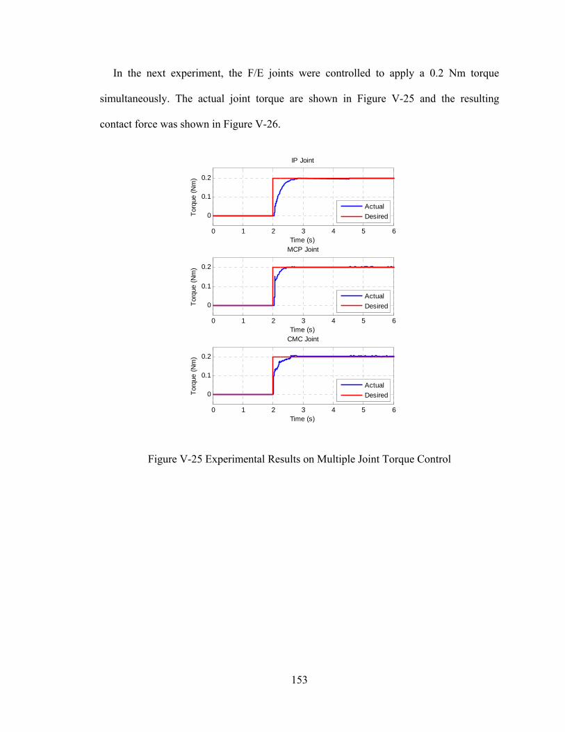
153
In the next experiment, the F/E joints were controlled to apply a 0.2 Nm torque
simultaneously. The actual joint torque are shown in Figure V-25 and the resulting
contact force was shown in Figure V-26.
Figure V-25 Experimental Results on Multiple Joint Torque Control
0 1 2 3 4 5 6
0
0.1
0.2
Time (s)
Tor
que
(Nm
)
IP Joint
0 1 2 3 4 5 6
0
0.1
0.2
Time (s)
Tor
que
(Nm
)
MCP Joint
0 1 2 3 4 5 6
0
0.1
0.2
Time (s)
Tor
que
(Nm
)
CMC Joint
Actual
Desired
Actual
Desired
Actual
Desired
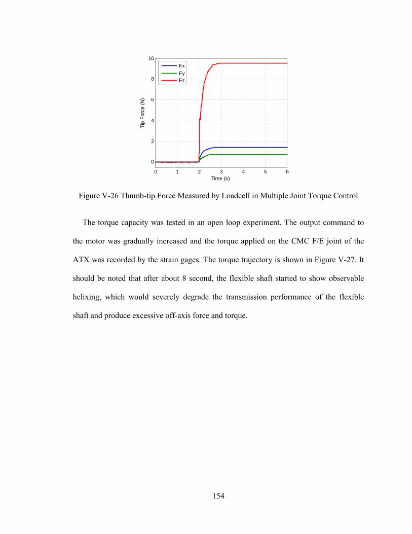
154
Figure V-26 Thumb-tip Force Measured by Loadcell in Multiple Joint Torque Control
The torque capacity was tested in an open loop experiment. The output command to
the motor was gradually increased and the torque applied on the CMC F/E joint of the
ATX was recorded by the strain gages. The torque trajectory is shown in Figure V-27. It
should be noted that after about 8 second, the flexible shaft started to show observable
helixing, which would severely degrade the transmission performance of the flexible
shaft and produce excessive off-axis force and torque.
0 1 2 3 4 5 6
0
2
4
6
8
10
Time (s)
Tip
For
ce (
N)
Fx
FyFz
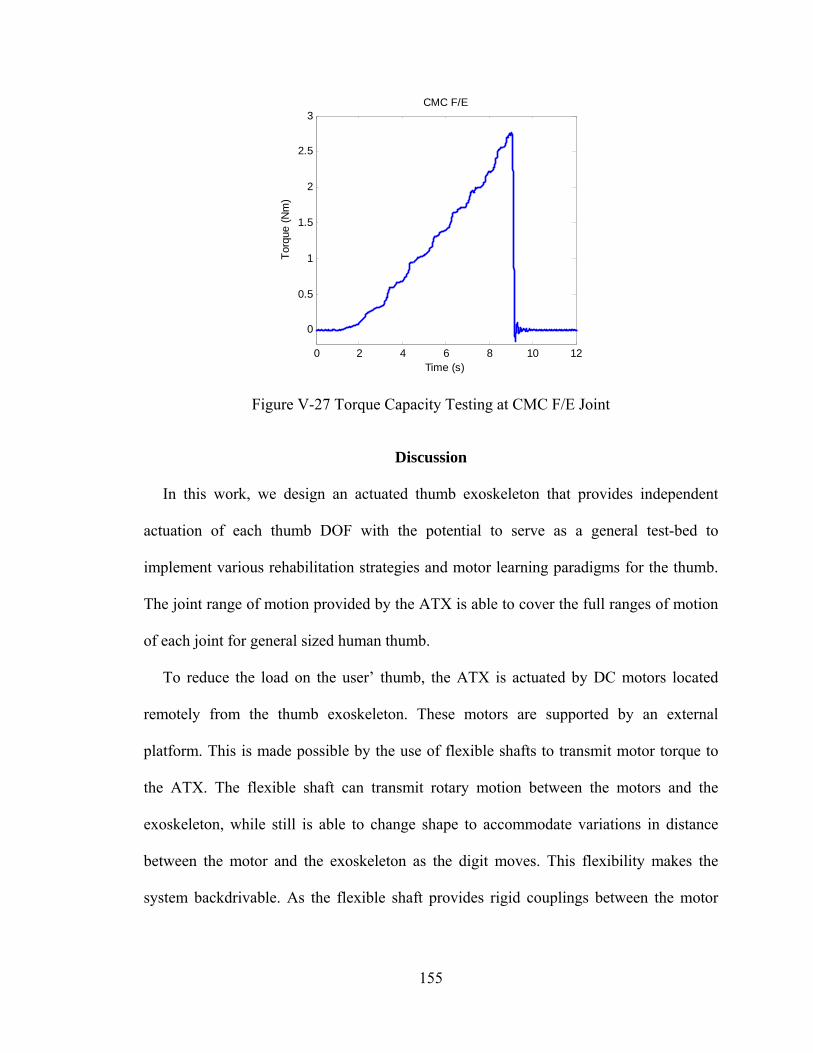
155
Figure V-27 Torque Capacity Testing at CMC F/E Joint
Discussion
In this work, we design an actuated thumb exoskeleton that provides independent
actuation of each thumb DOF with the potential to serve as a general test-bed to
implement various rehabilitation strategies and motor learning paradigms for the thumb.
The joint range of motion provided by the ATX is able to cover the full ranges of motion
of each joint for general sized human thumb.
To reduce the load on the user’ thumb, the ATX is actuated by DC motors located
remotely from the thumb exoskeleton. These motors are supported by an external
platform. This is made possible by the use of flexible shafts to transmit motor torque to
the ATX. The flexible shaft can transmit rotary motion between the motors and the
exoskeleton, while still is able to change shape to accommodate variations in distance
between the motor and the exoskeleton as the digit moves. This flexibility makes the
system backdrivable. As the flexible shaft provides rigid couplings between the motor
0 2 4 6 8 10 12
0
0.5
1
1.5
2
2.5
3CMC F/E
Time (s)
Tor
que
(Nm
)
156
shaft and the driving shaft of the ATX, it can rotate the joint in either the clockwise or the
counter-clockwise direction, and thus, only one motor is needed for each DOF.
Kinematic and kinetic transmission performance of the flexible shaft was tested in our
experiments. Transmission loss in motion was not observed under low torque while it did
exist when the torque load went beyond 0.5 Nm. Transmission loss in torque was also
observed as the torque went up. These observations confirmed the need to measure the
joint position and joint torque directly at the exoskeleton joint by potentiometer and strain
gages, respectively. The potentiometer and strain gages were calibrated for all joints and
showed strong linearity and minimal hysteresis.
We also examined the off-axis forces and torques produced by the flexible shaft at its
distal attachment. In addition to the desired torque that was transmitted about the z-axis,
small residual moments were present about other axes and small forces were produced as
well, with magnitudes dependent upon the shaft configuration. These residual forces and
moments could be mitigated by placing an outer casing around the shaft to reduce the
helixing of the shaft. Note that the relatively high torque is only needed when the user
applies force on an object or has exceptionally high stiffness in the thumb joint. In such
cases, the effect of off-axis forces and moments will be minimized due to the structural
rigidity of the thumb. Moreover, the structure of the exoskeleton is designed to reject
some of these unwanted moments/forces. The pin joints only allow rotation about the
desired axis and strong coupling between the ATX and the hand resists the small off-axis
forces. We tested our prototype on several subjects and they were largely unaware of any
off-axis moments or forces.
157
The kinematic performance of the ATX was examined in a set of experiments
including: the tracking of a ramp trajectory, examination of peak instantaneous velocity
and tracking of sinusoidal trajectory for each individual joint, and the tracking of
different ramp trajectories for multiple joints simultaneously.
The tracking of the ramp trajectory for individual joint was successful for all 5 joints.
The RMS error at steady state was under 0.33° for all 5 joints. As the minimum
displacement for perception of movement by human is 1° [47], this level of accuracy is
sufficient. There was, however, a delay in the kinematic response. This might result from
the flexible shaft having to undergo an initial winding up before beginning to transmit
movement. The static friction in the transmission would also cause some delay and this
effect could be reduced by adding friction compensation in the control loop.
The tracking of trajectories with high instantaneous velocity was also tested. The
maximum velocities observed were 450°/s, 550°/s, 650°/s, 520°/s and 900°/s from J1 to
J5, respectively. These joint velocities together will be sufficient to produce the angular
velocity at the thumb-tip at the level of 1000°/s, which meets our design requirement.
Moreover, in the next experiment, the ATX was able to track sinusoidal trajectories with
angular frequency of 4π (2 Hz) for J1, J3, J4 and J5, and 3π (1.5 Hz) for J2. These two
experiments demonstrate the high speed and response capacity of the ATX.
The tracking of different ramp trajectories for multiple joints showed some impressive
results. In the trial of controlling all F/E joints, all active F/E joints were able to track the
desired trajectories while no motion was observed at the passive Ab/Ad joints. On the
other hand, in the trial of controlling all Ab/Ad joints, all active Ab/Ad joints were able to
track the desired trajectories while no motion was observed at the passive F/E joints of
158
MCP and IP. Although the CMC F/E joint showed 8° degree of flexion, it is reasonable
as this joint took the overall load of the ATX. This motion could be minimized by
actively control the CMC F/E joint. These results indicate the F/E and the Ab/Ad motion
of the ATX is independent and minimal off-axis force/torque is produced in the flexible
shaft transmission. In the next trial, all 5 joints were controlled to track different ramp
trajectories. The results show that the ATX can produce independent position control at
each joint simultaneously.
The kinetic performance of the ATX was also examined in our experiments. All 5
joints were able to produce the desired torque accurately. The torque capacity tested at
CMC F/E joint showed that the ATX was able to produce 2.5 Nm torque. However, due
to the helixing observed in the experiment, the maximum torque transmitted by the
current flexible shaft should not exceed 2 Nm to avoid excessive off-axis force caused by
the helixing. In this case, the torque capacity of this joint is 20% lower than our goal of
torque capacity. But the 2.0 Nm torque capacity is still much more than those reported by
other devices. Moreover, as the CMC F/E joint is the first joint and is supported by the
external platform, we can choose a thicker flexible shaft with higher torque rating to
provide the 2.5 Nm torque.
From the experimental results and analysis, we believe that the current design comes
close to our design requirements and is able to provide controllable independent actuation
to each thumb joint with high speed and torque capacities. These capabilities, which
exceed those of other current exoskeletons in power, speed, and actuated DOF, will
permit careful evaluation of the motor control of stroke survivors and of different
rehabilitation strategies. For example, the high achievable speeds will permit assessment
159
of spasticity [48] and isokinetic strength and power. The large torque capabilities and
individual actuation of each DOF will be able to overcome the coactivation in the
affected thumb and permit evaluation of peak strength.
Conclusion and Future Work
This work presents the design and performance testing of an actuated thumb
exoskeleton (ATX) that permits independent bi-directional actuation in each of the 5
DOF of the thumb using a mechanism that has 5 active DOF and 3 passive DOF. The
transmission system using flexible shaft is able to transmit considerable joint torques to
the user while still allowing backdrivability. Independent control of each thumb joint and
the ability to provide sufficient torque to overcome the excessive coactivation and
increased stiffness in the affected thumb are important criteria in designing a general
platform to implement thumb rehabilitation therapies and motor learning paradigms.
Experiments of closed-loop position and torque control were conducted and the results
showed that both the position and torque control performance was satisfying.
In the future work, we will implement different rehabilitation strategies on the ATX,
e.g., low-impedance, force perturbation, passive, active and assist-as-needed strategies. A
high-level supervisory controller will be developed to coordinate these rehabilitation
strategies. Further, the ATX will be coupled with an actuated finger exoskeleton (AFX)
[49] that we have developed for the index finger to implement rehabilitation strategies in
restoring control of pinch movements following stroke.
160
References
[1] American Heart Association: Heart and Stroke Statistical Update, http://www.Americanheart.org/statistics/stroke.htm, 2009.
[2] R. Bonita, Steward, A, Beaglehole, R, "International trends in stroke mortality: 1970-1985," Stroke, vol. 21, pp. 989-992, 1990.
[3] J. P. Broderick, S. J. Phillips, J. P. Whisnant, W. M. O'Fallon, and E. J. Bergstralh, "Incidence rates of stroke in the eighties: the end of the decline in stroke?," Stroke, vol. 20, pp. 577-582, 1989.
[4] C. S. Gray, J. M. French, D. Bates, N. E. Cartlidge, 0. F. James, and G. Venables, "Motor recovery following acute stroke," Age Ageing, vol. 19, pp. 179-84, 1990.
[5] H. Nakayama, H. S. Jorgensen, H. 0. Raaschou, and T. S. Olsen, "Recovery of upper extremity function in stroke patients: The Copenhagen Stroke Study," Arch Phys Med Rehabilitation, vol. 75, pp. 394-398, 1994.
[6] V. M. Parker, D. T. Wade, and R. Langton Hewer, "Loss of arm function after stroke: measurement, frequency, and recovery." Int. Rehab Med, vol. 8, pp. 69-73, 1986.
[7] C. A. Trombly, "Stroke," in Occupational Therapy for Physical Dysfunction, Baltimore: Williams and Wilkins, 1989, pp. 454-471.
[8] D. Wade, "The epidemiologically based needs assessment reviews." Health Care Needs Assessment, Volume I, J. Raftery, Ed., 1994, pp. 111-255.
[9] S. L. Wolf, S. Blanton, H. Baer, J. Breshears, and A. J. Butler, "Repetitive task practice: a critical review of constraint-induced movement therapy in stroke," Neurologist, vol. 8, pp. 325-3 8, 2002.
[10] C. J. Winstein, D. K. Rose, S. M. Tan, R. Lewthwaite, H. C. Chui, and S. P. Azen, "A randomized controlled comparison of upper-extremity rehabilitation strategies in acute stroke: A pilot study of immediate and long-term outcomes," Arch Phys Med Rehab, vol. 85, pp. 620-8, 2004.
[11] S. J. Page, S. Sisto, P. Levine, and R. E. McGrath, "Efficacy of modified constraint-induced movement therapy in chronic stroke: a single-blinded randomized controlled trial," Arch Phys Med Rehab, vol. 85, pp. 14-8, 2004.
[12] T. A. Jones, C. J. Chu, L. A. Grande, and A. D. Gregory, "Motor skills training enhances lesion-induced structural plasticity in the motor cortex of adult rats," JNeurosci, vol. 19, pp. 10153-63, 1999.
[13] J. A. Kleim, T. A. Jones, and T. Schallert, "Motor enrichment and the induction of plasticity before or after brain injury," Neurochem Res, vol. 28, pp. 1757-69, 2003.
161
[14] T. A. Jones and T. Schallert, "Use-dependent growth of pyramidal neurons after neocortical damage," JNeurosci, vol. 14, pp. 2140-52, 1994.
[15] J. Liepert, H. Bauder, W. H. R. Miltner, E. Taub, and C. Weiller, "Treatment-induced cortical reorganization after stroke in humans," Stroke, vol. 31, pp. 1210-1216, 2000.
[16] J. Liepert, W. H. R. Miltner, H. Bauder, M. Sommer, C. Dettmers, E. Taub, and C. Weiller, "Motor cortex plasticity during constraint-induced movement therapy in stroke patients," Neurosci Letters, vol. 250, pp. 5-8, 1998.
[17] L. R. Macclellan, D. D. Bradham, J. Whitall, B. Volpe, P. D. Wilson, J. Ohlhoff, C. Meister, N. Hogan, H. I. Krebs, and C. T. Bever, Jr., "Robotic upper-limb neurorehabilitation in chronic stroke patients," J Rehabil Res Dev, vol. 42, pp. 717-22, 2005.
[18] M. Ferraro, J. J. Palazzolo, J. Krol, H. I. Krebs, N. Hogan, and B. T. Volpe, "Robot-aided sensorimotor arm training improves outcome in patients with chronic stroke," Neurology, vol. 61, pp.1604-7, 2003.
[19] D. J. Reinkensmeyer, L. E. Kahn, M. Averbuch, A. McKenna-Cole, B. D. Schmit, and W. Z. Rymer, "Understanding and treating arm movement impairment after chronic brain injury: progress with the ARM guide," J Rehabil Res Dev, vol. 37, pp. 653-62, 2000.
[20] P. S. Lum, C. G. Burgar, P. C. Shor, M. Majmundar, and M. Van der Loos, "Robot-assisted movement training compared with conventional therapy techniques for the rehabilitation of upperlimb motor function after stroke," Arch Phys Med Rehabil, vol. 83, pp. 952-9, 2002.
[21] Gupta, A., O'Malley, M. K., Patoglu, V. and Burgar, C., “Design, control and performance of RiceWrist: a force feedback wrist exoskeleton for rehabilitation and training” The International Journal of Robotics Research, 27, 233-251, 2008.
[22] B. T. Volpe, H. I. Krebs, N. Hogan, 0. L. Edelstein, C. Diels, and M. Aisen, "A novel approach to stroke rehabilitation: robotaided sensorimotor stimulation," Neurology, vol. 54, pp. 1938- 44, 2000.
[23] L. E. Kahn, M. L. Zygman, W. Z. Rymer, and D. J. Reinkensmeyer, "Effect of robot-assisted and unassisted exercise on functional reaching in chronic hemiparesis," presented at 23rd Annual IEEE Engineering in Medicine and Biology Conference, Istanbul, Turkey, 2001.
[24] J. L. Patton, M. E. Stoykov, M. Kovic, and F. A. Mussa-Ivaldi, "Evaluation of robotic training forces that either enhance or reduce error in chronic hemiparetic stroke survivors," Exp Brain Res, vol. 168, pp. 368-83, 2006.
[25] S. Hesse, C. Werner, M. Pohl, S. Rueckriem, J. Mehrholz, and M. L. Lingnau, "Computerized arm training improves the motor control of the severely affected
162
arm after stroke: a single-blinded randomized trial in two centers," Stroke, vol. 36, pp. 1960-6, 2005.
[26] Sergei V Adamovich, Gerard G Fluet, Abraham Mathai, Qinyin Qiu, Jeffrey Lewis and Alma S Merians, “Design of a complex virtual reality simulation to train finger motion for persons with hemiparesis: a proof of concept study”, Journal of NeuroEngineering and Rehabilitation 2009, 6:28.
[27] D. Jack, R. Boian, A. S. Merians, M. Tremaine, G. C. Burdea, S. V. Adamovich, M. Recce, and H. Poizner, "Virtual realityenhanced stroke rehabilitation," IEEE Trans Neural Syst Rehabil Eng, vol. 9, pp. 308-18, 2001.
[28] C. D. Takahashi, L. Der-Yeghiaian, V. Le, R. R. Motiwala, and S. C. Cramer, "Robot-based hand motor therapy after stroke," Brain, vol. 131, pp. 425-37, Feb 2008.
[29] L. Dovat, O. Lambercy, R. Gassert, T. Maeder, T. Milner, T. C. Leong, and E. Burdet, "HandCARE: a cable-actuated rehabilitation system to train hand function after stroke," IEEE Trans Neural Syst Rehabil Eng, vol. 16, pp. 582-91, Dec 2008.
[30] A. Wege and G. Hommel, "Development and control of a hand exoskeleton for rehabilitation of hand injuries," IEEE/RSJ International Conference on Intelligent Robots and Systems, Edmonton, Canada, 2005.
[31] I. Sarakoglou, N. G. Tsagarakis, and D. G. Caldwell, "Occupational and physical therapy using a hand exoskeleton based exerciser," presented at IEEE/RSJ International Conference on Intelligent Robots and Systems, Sendai, Japan, 2004.
[32] M. DiCicco, L. Lucas, and Y. Matsuoka, "Strategies for an EMG-controlled orthotic exoskeleton for the hand," IEEE International Conference on Robotics and Automation, New Orleans, USA, 2004.
[33] Kawasaki H, Ito S, Ishigure Y, Nishimoto Y, Aoki T, Mouri H, et al. “Development of a hand motion assist robot for rehabilitation therapy by patient self-motion control”. IEEE 10th Intl Conf Rehab Rob. Noordwijk, The Netherlands, 2007: 234-240.
[34] Giurintano DJ, Hollister AM, Buford WL, Thompson DE, Myers LM. “A virtual five-link model of the thumb”, Med Eng Phys 1995; 17: 297-303.
[35] Hollister AM, Buford WL, Myers LM, Giurintano DJ, Novick A. “The axes of rotation of the thumb carpometacarpal joint”, J Orthop Res 1992; 10: 454-460.
[36] Hollister A, Giurintano DJ, Buford WL, Myers LM, Novick A. “The axes of rotation of the thumb interphalangeal and metacarpophalangeal joints.”, Clin Orthop Relat Res. 1995 Nov;(320):188-93.
[37] Santos VJ, Valero-Cuevas FJ. “Reported anatomical variability naturally leads to multimodal distributions of Denavit-Hartenberg parameters for the human thumb”, IEEE Trans Biomed Eng 2006; 53: 155-63.
163
[38] D. G. Kamper and W. Z. Rymer, "Impairment of voluntary control of finger motion following stroke: role of inappropriate muscle coactivation," Muscle Nerve, vol. 24, pp. 673-81, May 2001.
[39] D. H. Saunders, et al., "Association of activity limitations and lower-limb explosive extensor power in ambulatory people with stroke," Arch Phys Med Rehabil, vol. 89, pp. 677-83, Apr 2008.
[40] W. P. Cooney, 3rd, M. J. Lucca, E. Y. Chao, and R. L. Linscheid, "The kinesiology of the thumb trapeziometacarpal joint," J Bone Joint Surg Am, 1981, vol. 63, pp. 1371-81.
[41] Buchholz B., Armstrong TJ., “A kinematic model of the human hand to evaluate its prehensile capabilities”, J Biomech 1992 Feb; 25(2):149-62.
[42] J. A. Katarincic, "Thumb kinematics and their relevance to function," Hand Clin, 2001, vol. 17, pp. 169-74.
[43] Gutnik, B., Hudson, G., Ricacho, G., Skirius, J., “Power of Performance of the Thumb Adductor Muscles: Effect of Laterality and Gender”, Medicina (Kaunas), 2006, 42(8), 654-656.
[44] Vikash Gupta, “Kinematic analysis of a thumb-exoskeleton system for post stroke rehabilitation”, Thesis (M.S. in Mechanical Engineering), Vanderbilt University, Aug. 2010.
[45] Gowland C, Stratford P, Ward M, Moreland J, Torresin W, Van Hullenaar S, Sanford J, Barreca S, Vanspall B, Plews N. Measuring physical impairment and disability with the chedoke-mcmaster stroke assessment. Stroke. 1993;24:58-63
[46] xPC target, Mathworks, http://www.mathworks.com/help/toolbox/xpc/
[47] Gandevia, S.C., et al., Proprioceptive sensation at the terminal joint of the middle finger. J Physiol, 1983. 335: p. 507-17.
[48] D. G. Kamper and W. Z. Rymer, "Quantitative features of the stretch response of extrinsic finger muscles in hemiparetic stroke," Muscle Nerve, vol. 23, pp. 954-61, Jun 2000.
[49] C. Jones, F. Wang, et al, “Control and Kinematic Performance Analysis of an Actuated Finger Exoskeleton for Hand Rehabilitation Following Stroke”, IEEE International Conference on Biomedical Robotics and Biomechatronics, Tokyo, Japan, 2010.
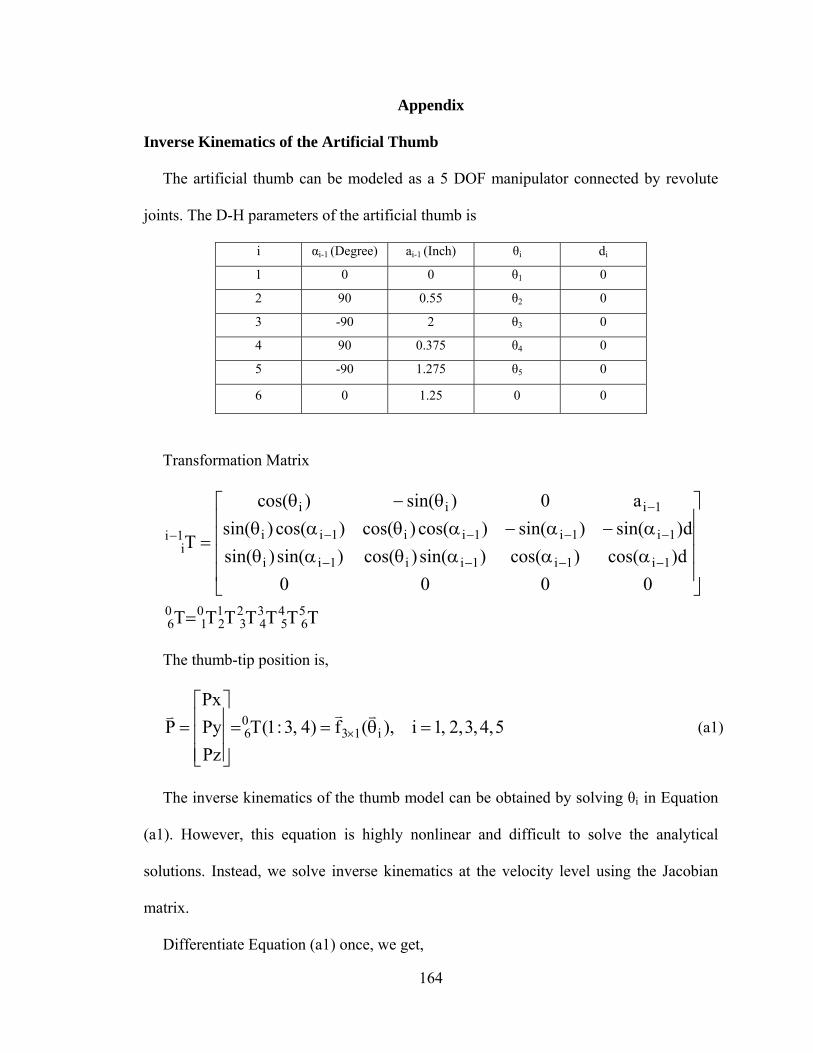
164
Appendix
Inverse Kinematics of the Artificial Thumb
The artificial thumb can be modeled as a 5 DOF manipulator connected by revolute
joints. The D-H parameters of the artificial thumb is
i αi-1 (Degree) ai-1 (Inch) θi di
1 0 0 θ1 0
2 90 0.55 θ2 0
3 -90 2 θ3 0
4 90 0.375 θ4 0
5 -90 1.275 θ5 0
6 0 1.25 0 0
Transformation Matrix
TTTTTTT
0000
d)cos()cos()sin()cos()sin()sin(
d)sin()sin()cos()cos()cos()sin(
a0)sin()cos(
T
56
45
34
23
12
01
06
1i1i1ii1ii
1i1i1ii1ii
1iii
1ii
The thumb-tip position is,
5,4,3,2,1i),(f)4,3:1(T
Pz
Py
Px
P i1306
(a1)
The inverse kinematics of the thumb model can be obtained by solving θi in Equation
(a1). However, this equation is highly nonlinear and difficult to solve the analytical
solutions. Instead, we solve inverse kinematics at the velocity level using the Jacobian
matrix.
Differentiate Equation (a1) once, we get,
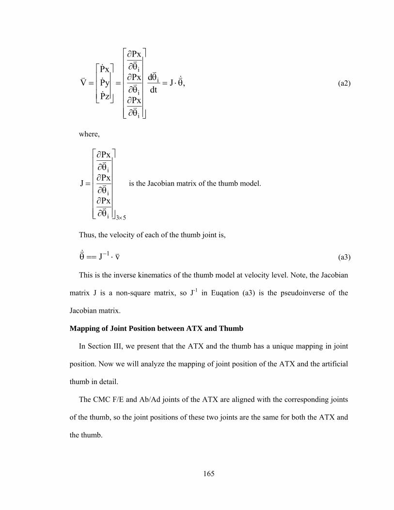
165
,Jdt
d
Px
Px
Px
zP
yP
xP
V i
i
i
i
(a2)
where,
53i
i
i
Px
Px
Px
J
is the Jacobian matrix of the thumb model.
Thus, the velocity of each of the thumb joint is,
vJ 1 (a3)
This is the inverse kinematics of the thumb model at velocity level. Note, the Jacobian
matrix J is a non-square matrix, so J-1 in Euqation (a3) is the pseudoinverse of the
Jacobian matrix.
Mapping of Joint Position between ATX and Thumb
In Section III, we present that the ATX and the thumb has a unique mapping in joint
position. Now we will analyze the mapping of joint position of the ATX and the artificial
thumb in detail.
The CMC F/E and Ab/Ad joints of the ATX are aligned with the corresponding joints
of the thumb, so the joint positions of these two joints are the same for both the ATX and
the thumb.
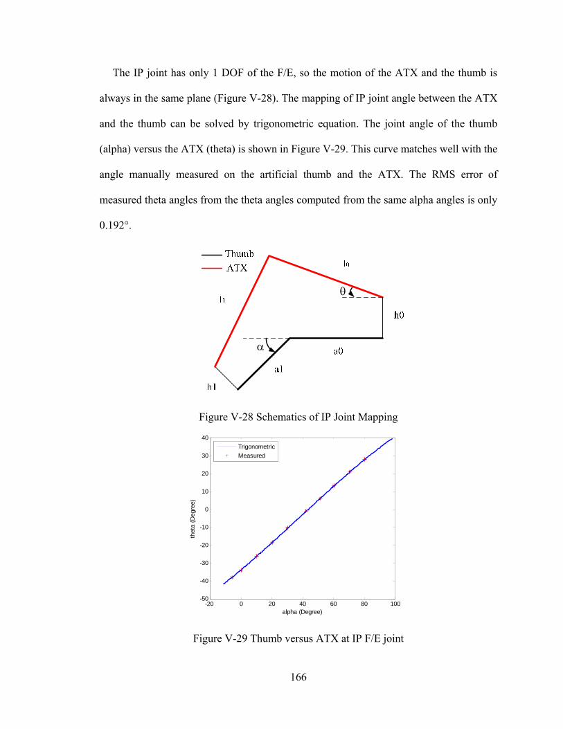
166
The IP joint has only 1 DOF of the F/E, so the motion of the ATX and the thumb is
always in the same plane (Figure V-28). The mapping of IP joint angle between the ATX
and the thumb can be solved by trigonometric equation. The joint angle of the thumb
(alpha) versus the ATX (theta) is shown in Figure V-29. This curve matches well with the
angle manually measured on the artificial thumb and the ATX. The RMS error of
measured theta angles from the theta angles computed from the same alpha angles is only
0.192°.
Figure V-28 Schematics of IP Joint Mapping
Figure V-29 Thumb versus ATX at IP F/E joint
-20 0 20 40 60 80 100-50
-40
-30
-20
-10
0
10
20
30
40
alpha (Degree)
thet
a (D
egre
e)
Trigonometric
Measured
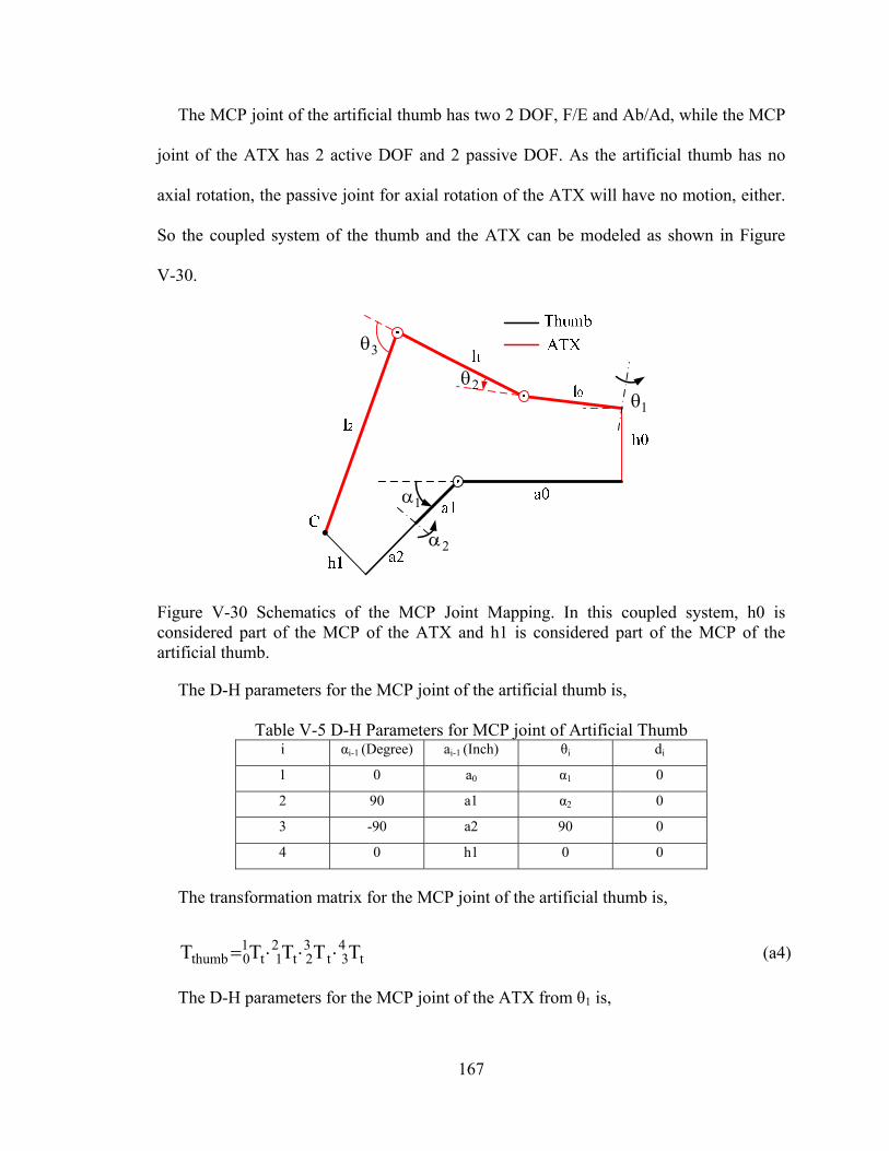
167
The MCP joint of the artificial thumb has two 2 DOF, F/E and Ab/Ad, while the MCP
joint of the ATX has 2 active DOF and 2 passive DOF. As the artificial thumb has no
axial rotation, the passive joint for axial rotation of the ATX will have no motion, either.
So the coupled system of the thumb and the ATX can be modeled as shown in Figure
V-30.
12
3
1
2
Figure V-30 Schematics of the MCP Joint Mapping. In this coupled system, h0 is considered part of the MCP of the ATX and h1 is considered part of the MCP of the artificial thumb.
The D-H parameters for the MCP joint of the artificial thumb is,
Table V-5 D-H Parameters for MCP joint of Artificial Thumb i αi-1 (Degree) ai-1 (Inch) θi di
1 0 a0 α1 0
2 90 a1 α2 0
3 -90 a2 90 0
4 0 h1 0 0
The transformation matrix for the MCP joint of the artificial thumb is,
t43t
32t
21t
10thumb TTTTT (a4)
The D-H parameters for the MCP joint of the ATX from θ1 is,
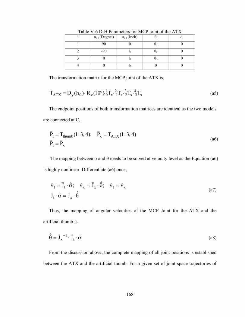
168
Table V-6 D-H Parameters for MCP joint of the ATX i αi-1 (Degree) ai-1 (Inch) θi di
1 90 0 θ1 0
2 -90 l0 θ2 0
3 0 l1 θ3 0
4 0 l2 0 0
The transformation matrix for the MCP joint of the ATX is,
x43x
32x
21x
10z0yATX TTTT)10(R)h(DT (a5)
The endpoint positions of both transformation matrices are identical as the two models
are connected at C,
xt
ATXxthumbt
PP
)4,3:1(TP);4,3:1(TP
(a6)
The mapping between α and θ needs to be solved at velocity level as the Equation (a6)
is highly nonlinear. Differentiate (a6) once,
xt
xtxxtt
JJ
vv;Jv;Jv (a7)
Thus, the mapping of angular velocities of the MCP Joint for the ATX and the
artificial thumb is
t1
x JJ (a8)
From the discussion above, the complete mapping of all joint positions is established
between the ATX and the artificial thumb. For a given set of joint-space trajectories of

169
the artificial thumb and initial configuration of the artificial thumb and the ATX, the
corresponding joint-space trajectories of the ATX will be obtained, and vice versa.
170
CHAPTER VI
CONTRIBUTIONS AND FUTURE WORK
Contributions
The research work presented in this dissertation focuses in the area of robot-assisted
upper extremity rehabilitation following stroke. We have worked towards improving
robot-assisted upper extremity rehabilitation in three different approaches: enhancement
of existing robotic systems, implementation and evaluation of novel rehabilitation
training strategies, and design and development of new robotic systems. The main
contributions of this work are:
1) Design of a high-level supervisory controller for the existing rehabilitation robotic
system to automatically adjust the rehabilitation therapy according to the user’s verbal
feedback. This high-level supervisory controller monitors the task execution and safety,
and makes task adjustment according to the recognized verbal feedback from the user
during the task execution to impart effective therapy an automated manner. This
enhancement allows the user-robot direct interaction, and reduces the intervention and
workload of the therapists.
2) Evaluation of the impact of the integrated training method of assist-as-needed and
visual error augmentation in upper limb rehabilitation. A new training strategy is
proposed which integrates the assist-as-needed and visual error augmentation strategies.
This new strategy is implemented in the existing robotic system. A crossover study with
20 subjects is designed to assess the impact of the integrated training method of these two
171
strategies on robot-assisted upper limb rehabilitation. Statistical analysis of the
experimental results has demonstrated the proposed integrated training strategy has the
potential to improve the efficacy of the robot-assisted upper limb rehabilitation.
3) Control of an actuated finger exoskeleton (AFX). The real-time control system is
developed for the AFX with position and torque control. The position and force controller
is PI controller with friction compensation and feedforward compensation. A planner is
designed to distribute the control command to the appropriate motor in the motor pair.
Experimental results show the AFX has independent actuation of each joint with full
range of finger motion, high backdrivability, high speed and torque capacities that will
facilitate the scientific research of finger rehabilitation and motor control of stroke
survivors.
4) Design and development of an actuated thumb exoskeleton (ATX). An ATX that
has 5 active degree-of-freedoms (DOF) and 3 passive DOF is designed to provide
independent actuation for each DOF of the human thumb. Sensory, actuation and control
systems are developed to permit real-time control. The ATX is tested in experiments and
the performance comes close to all the design goals. The ability to provide independent
actuation of each DOF of the thumb with high torque and speed capacity will allow the
ATX to serve as a test bed to facilitate the thumb rehabilitation and motor control study.
Future Work
The future work remains focused on improving the robot-assisted rehabilitation.
Building on the results in this dissertation, there are many exciting research directions
that will promote this research area and benefit the stroke population as follows:
172
1) Implementation and evaluation of various rehabilitation strategies and motor
control paradigms for the hand with the AFX and ATX. The capabilities of the AFX and
ATX permit the implementation of various rehabilitation strategies and motor control
paradigms. Systematically experiments on human subjects will demonstrate the
differences in efficacy of these strategies in improving hand rehabilitation, thus help
therapist find the more efficient way to conduct rehabilitation.
2) Coordinated control of the AFX and ATX. With both the AFX and ATX being
controlled separately, the next step is to coordinately control these two devices to conduct
practical hand tasks, e.g., pinching and rolling tasks. A high-level supervisory controller
will be needed to coordinate the two separate devices and generate reference task for both
devices.
3) Design of a full hand exoskeleton for all four fingers and the thumb. The human
hand has 21 DOF in total, namely, 4 DOF for each finger and 5 DOF for the thumb. A
full hand exoskeleton will be able to provide rehabilitation therapies to each digits of the
hand and retrain the full hand function of the stroke survivors. This exoskeleton can also
facilitate research in sensorimotor control, especially as it relates to integration of
proprioception. This kinesthetic sense is fundamental to control of movement, and could
be further incorporated into user control of assistive technology, such as robotic or
prosthetic hands or neuromuscular stimulation systems.