Embed Size (px)
Citation preview

Design and Development of an Upper Limb Prosthesis
Vanessa Mariana Alves Carvalho Lopes
Thesis to obtain the Master of Science Degree in
Biomedical Engineering
Supervisors: Prof. Miguel Pedro Tavares da Silva
Prof. Marco Alexandre de Oliveira Leite
Examination Committee
Chairperson: Prof.ª Patrícia Margarida Piedade Figueiredo
Supervisor: Prof. Miguel Pedro Tavares da Silva
Members of the Committee: Prof. Paulo Rui Alves Fernandes
Dr. Manuel Cassiano Neves
June 2017

i
Agradecimentos
Este trabalho não teria sido possível de realizar sem o auxílio da restante equipa de trabalho, bem
como o apoio da minha família e amigos.
Quero agradecer aos meus orientadores do Instituto Superior Técnico, o Prof. Miguel Tavares da Silva
e o Prof. Marco Leite, por toda a orientação deste trabalho, todos os brain stormings e pelas palavras
de motivação nos momentos de maior dificuldade.
À minha orientadora do Hospital de D. Estefânia, a Dra Maria José Costa, pelas noções médicas e
fisiológicas associadas à temática do trabalho e toda a documentação fornecida.
Aos pais, agradeço toda a disponibilidade, fundamental para o sucesso deste trabalho.
À Rita Cardoso, pelo trabalho inicial que desenvolvemos em conjunto, bem como pelas noções em
SolidWorks e MeshLab que me forneceu.
O meu muito obrigada ao João Fernandes e ao Ricardo Pereira pelo apoio incansável na impressão
3D e pelas sugestões que auxiliaram o decorrer deste trabalho. Agradeço também ao Sérgio Gonçalves
pela discussão de ideias e interesse no meu trabalho.
Aos meus amigos da faculdade, com quem partilhei as alegrias e desgostos da vida de estudante. Em
especial à Elisa Pacheco, à Cátia Franco e ao José Portela por todo o companheirismo e apoio
incansável ao longo destes anos. À Patrícia Ferreira e à Joana Capacete, que embora tenham entrado
no meu percurso académico mais recentemente, me auxiliaram sempre que possível.
À minha família, em especial aos meus pais por todo o apoio ao longo do meu percurso académico.
Sem o vosso esforço e os valores que me incutiram, esta etapa não teria sido possível. Um
agradecimento especial ao meu primo Ricardo Abrantes por ter sido o maior responsável por eu
escolher a Engenharia como área de formação. A vós agradeço ainda toda a motivação nas alturas
mais delicadas do trabalho e pela partilha da alegria aquando das minhas vitórias.
A todos, o meu sincero obrigado.

ii
Resumo
As desordens dos membros são um grupo de anomalias congénitas com significantes hipoplasias ou
aplasias de um ou mais ossos dos membros do corpo (Wilcox, Coulter, & Schmitz, 2015) e que ocorrem
em 1 entre 1300 a 2000 nascimentos (Gold, Westgate, & Holmes, 2011). Nestas situações, recomenda-
se que a primeira introdução de prótese na criança deve ser feita de acordo com o desenvolvimento
psicomotor da criança, nomeadamente quando for capaz de se sentar (Egermann, Kasten, & Thomsen,
2009; Yiğiter, Bayar, & Erbahçeci, 1999). Este procedimento estimulará as actividades bimanuais, a
consciência da simetria do corpo, bem como aumentará a probabilidade de, no futuro, próteses mais
complexas sejam bem aceites pelo utilizador. No entanto, há no mercado necessidade de próteses
personalizadas para crianças de tão pouca idade.
O objectivo deste trabalho é conceber e desenvolver uma prótese cosmética para uma criança de dois
anos com uma malformação congénita do membro superior direito. Esta tarefa foi realizada através de
projecto integrado por computador. Para tal, utilizaram-se as tecnologias de Digitalização
Tridimensional, Tomografia Computadorizada, Desenho Assistido por Computador e Manufactura
Aditiva.
Com a metodologia desenvolvida, pretende-se também definir uma metodologia inovadora para aplicar
a crianças que apresentem este tipo de deficiências. Para além disso, a metodologia obtida poderá ser
aplicada também a pessoas de outras idades.
Por fim, efectuou-se uma revisão bibliográfica do estado da arte de dispositivos ortoprotésicos para
membros superiores com acção mecânica e possíveis de fabricar através da manufactura aditiva. Após
este passo, foi sugerida e esboçada uma solução híbrida de dois destes dispositivos, adequada à
criança do caso de estudo deste trabalho.
Palavras-Chave: Próteses Cosméticas, Digitalização 3D de Geometrias Anatómicas, Modelação
Geométrica, Fabrico Aditivo, Dispositivos Ortoprotésicos.

iii
Abstract
The Limb Deficiency Disorders (LDD) is a group of congenital anomalies with significant hypoplasia or
aplasia of one or more bones of the limbs (Wilcox et al., 2015) that occur in 1 in 1300 to 2000 births
(Gold et al., 2011). Initial upper limb prosthetic fitting is recommended according to the psychomotor
development of the child, namely when the child is able to sit independently (Egermann et al., 2009).
This procedure is intended to stimulate bimanual activities and body symmetry, as well as to improve
the acceptability of more complex prosthetic hand devices in the future. However, there is a need in
personalized prosthetic hands for children of such a young age.
The objective of this work is to design and develop a cosmetic prosthesis device for a two-year-old child
with a congenital malformation of the right upper limb. This task is performed with computer-integrated
design approach. The selected technologies are Tridimensional Scanning (3D SCAN), Computed
tomography (CT), Computer aided design (CAD) and Addictive Manufacturing (AM).
Furthermore, a novel methodology was established to apply to the design of prosthetics to children with
this kind of disabilities. In this way, the approach achieved throughout this case study may also be
applied to people of other ages.
Last objective of this work is to sum up the state of the art of body-powered hand prostheses, fabricated
through additive manufacturing. After this, a draft of a body-powered solution was suggested to the child
of this case study.
Keywords: Cosmetic Prosthesis, 3D Anatomic Geometries Acquisition, Computed Aided Design,
Computer Aided Manufacturing, Orthopaedic Devices.


v
Index
Agradecimentos ....................................................................................................................................... i
Resumo .....................................................................................................................................................ii
Abstract ................................................................................................................................................... iii
Index ......................................................................................................................................................... v
List of Tables ........................................................................................................................................... vii
List of Figures ........................................................................................................................................... ix
List of Acronyms .................................................................................................................................... xiii
Chapter 1 ................................................................................................................................................. 1
Introduction ............................................................................................................................................. 1
1.1 Motivation ............................................................................................................................... 1
1.2 Objectives ................................................................................................................................ 2
1.3 State of the art ........................................................................................................................ 2
1.4 Main contributes ..................................................................................................................... 7
1.5 Structure and Organization ..................................................................................................... 8
Chapter 2 ............................................................................................................................................... 11
Upper limb disorders ............................................................................................................................. 11
2.1 The problem .......................................................................................................................... 11
2.1.1 Etiology ................................................................................................................................. 11
2.1.2 Upper limb disorders classification ...................................................................................... 12
2.2 Clinical procedures ................................................................................................................ 15
2.3 Historical evolution of limb prostheses ................................................................................. 17
Chapter 3 ............................................................................................................................................... 23
Concept development ........................................................................................................................... 23
3.1 Clinical case ........................................................................................................................... 23
3.2 The concept ........................................................................................................................... 24
3.3 The methodology .................................................................................................................. 25
3.3.1 Anatomical geometry acquisition ................................................................................. 25
3.3.1.1 Amputated limb geometry acquisition...................................................................... 25
3.3.1.2 Opposite limb geometry acquisition ......................................................................... 27
3.3.2 Geometry processing .................................................................................................... 28
3.3.2.1 Amputee limb geometry processing ......................................................................... 28
3.3.2.2 Opposite limb geometry processing ......................................................................... 33
3.3.3 Tests with the child........................................................................................................ 36

vi
3.3.4 CAD Prosthesis definition .............................................................................................. 37
3.3.4.1 Geometries alignment ............................................................................................... 37
3.3.4.2 Geometries adjustment............................................................................................. 38
3.3.5 Final tests with the child ................................................................................................ 39
Chapter 4 ............................................................................................................................................... 41
Computer-Aided Manufacturing (CAM) of the device .......................................................................... 41
4.1 Additive Manufacturing and its applicability in prosthetics.................................................. 41
4.2 NinjaFlex® and its suitability to hybrid printing technique ................................................... 45
4.3 Print specifications ................................................................................................................ 46
4.4 Production Costs ................................................................................................................... 55
Chapter 5 ............................................................................................................................................... 57
Concept generation for body-powered prostheses .............................................................................. 57
5.1 State of the art of 3D printable body-powered upper limb devices ..................................... 57
5.2 Suggestion of a 3D printable body-powered prosthesis for ................................................. 66
the child of the presented case study ............................................................................................... 66
Chapter 6 ............................................................................................................................................... 69
Conclusions and future work................................................................................................................. 69
6.1 Conclusions ............................................................................................................................ 69
6.2 Future work ........................................................................................................................... 71
References ............................................................................................................................................. 72
Appendix A – Print Parameters ......................................................................................... A-1

vii
List of Tables
Table 2.1 Designation of levels of transverse deficiencies of upper limbs (Day, 1991). ............. 13
Table 3.1: Values of stump measurements sketched in Figure 3.16. ......................................... 36
Table 3.2: Values of opposite upper limb measurements sketched in Figure 3.17. ................... 37
Table 4.1: Print specifications use for PLA print. ......................................................................... 46
Table 4.2: Print specifications used for the first NinjaFlex®-ABS dual extrusion print. .............. 48
Table 4.3: Print specifications used for the second NinjaFlex®-ABS dual extrusion print. ......... 49
Table 4.4: Print specifications used for the third NinjaFlex®-ABS dual extrusion print. ............. 50
Table 4.5: Print specifications used for the NinjaFlex® support structures print. ...................... 51
Table 4.6: Print specifications used for the third NinjaFlex®-PVA dual extrusion print. ............. 54

ix
List of Figures
Figure 1.1: Prosthetic elements: A: terminal devices (Green Prosthetics and Orthotics LLC, 2017); B:
suspension system (Upper Limb Prosthetics Information++, 2017); C: socket (Prweb, 2010); D: wrist
unit (Ottobock, 2016). ............................................................................................................................. 3
Figure 2.1: Description of longitudinal deficiencies of the upper limb (Day, 1991). ............................ 14
Figure 2.2: a) Examples of transverse deficiencies at different levels; b) Example of a longitudinal
deficiency (Day, 1991). .......................................................................................................................... 14
Figure 2.3: Strategy for the evaluation of congenital limb deficiencies (Wilcox et al., 2015). ............. 15
Figure 2.4: clamper devices: A: for adults (VirtualExpo Group, 2017c); B: for children (VirtualExpo
Group, 2017d). ...................................................................................................................................... 20
Figure 2.5: Cosmetic hand glove for children (VirtualExpo Group, 2017e). .......................................... 20
Figure 2.6: Mioelectric upper limb devices A: Mioelectric multiarticulated arm prosthesis for adults
(VirtualExpo Group, 2017a); B: Mioelectric multiarticulated hand prosthesis for adults (VirtualExpo
Group, 2017g); C: Mioelectric clamp/hook hand device for adults (VirtualExpo Group, 2017h). ........ 21
Figure 3.1: Right forearm X-ray. ............................................................................................................ 24
Figure 3.2: Scheme of the main tasks of the developed methodology ................................................ 25
Figure 3.3: Reflective dots referential. .................................................................................................. 26
Figure 3.4: 3D SCAN acquisition. ........................................................................................................... 27
Figure 3.5: Hill-formed geometry processing: A: first two planes added; B: parallel planes across
stump geometry, C: intersection curves. ............................................................................................. 28
Figure 3.6: Amputee limb geometry processing: A: inner surface definition; B: outer surface
definition; C: placement of a cylinder to fill in the space between inner and outer surfaces; D: final
stump geometry 2 mm thickness. ......................................................................................................... 29
Figure 3.7: Voronoi Mesh Forearm Geometry. ..................................................................................... 30
Figure 3.8: Stump proximal adjustments: A: parallel planes spaced 1.3 mm; B: third oblique plane; C:
cut extrude; D: final result. .................................................................................................................... 31
Figure 3.9: A, B and C: stump distal portion editions. ........................................................................... 32
Figure 3.10: A and B: stump distal portion editions. ............................................................................ 32
Figure 3.11: A and B: stump distal portion editions. ............................................................................. 33
Figure 3.12: CT data processing in ITK-SNAP: A: ROI definition; B: Lower and upper threshold
definition; C: bubble conquering; D: final conquered geometry. ......................................................... 34
Figure 3.13: A: Hand mesh after steps performed in Paraview; B: Mirrored hand after steps
performed in Blender. ........................................................................................................................... 35
Figure 3.14: Pipeline for the CT data processing. .................................................................................. 35
Figure 3.15: 3D printing results: A: Voronoi mesh amputee forearm geometry; B: Hand and left
forearm. ................................................................................................................................................. 36
Figure 3.16: A and B: Draft of the measurements performed to the stump. ....................................... 36
Figure 3.17: A, B and C: Draft of the measurements performed to the opposite upper limb. ............. 37
Figure 3.18: Geometry alignment procedures: A: Photography importation; B: Voronoi and stump
geometries alignment; C:
Hand alignment. 38
Figure 3.19: A: forearm mesh rip; B: results of rip reparation pipeline. ................................................ 38
Figure 3.20: A: hand mesh thickness; B: final cosmetic prosthesis geometry. ..................................... 39
Figure 3.21: Cosmetic prosthesis with its elastic socket. ...................................................................... 39
Figure 3.22: A and B: User with the PLA cosmetic prosthesis in different activities............................. 40
x
Figure 4.1: Printed object with support structures (Lombard, 2014). .................................................. 43
Figure 4.2: 3D printed anciliary structures: A: Raft; B: Skirt; C: Brim (Simplify3D, 2017b). .................. 44
Figure 4.3: Dual extrusion print technique: A: illustrative image (3DPrinterPrices.net, 2017); B: dual
extruder tool head of the used printed................................................................................................. 44
Figure 4.4: Ooze shield structure and the inner printed object (Tumakers, 2015). .............................. 45
Figure 4.5: PLA printing: A: Printing process; B: final print result . ....................................................... 47
Figure 4.6: Final result after support removal and polish. .................................................................... 47
Figure 4.7: NinjaFlex®-ABS first print results: A: Print result with auxiliar structures; B and C: Final
print result. ............................................................................................................................................ 48
Figure 4.8: Second NinjaFlex®-ABS print results: a) Print result with auxiliar structures; b) and c) Final
print result. ............................................................................................................................................ 50
Figure 4.9: Final print result of the third NinjaFlex®-ABS print. ........................................................... 51
Figure 4.10: Final result of the print with NinjaFlex® support structures............................................ 52
Figure 4.11: ABS support structures residues on a NinjaFlex® object. ................................................. 53
Figure 4.12: Final print result of NinjaFlex®-PVA print. ....................................................................... 55
Figure 5.1: Control motions used in both transradial and transhumeral body-powered prostheses: A:
glenohumeral flexion-forward motion of the upper arm about the shoulder; B: glenohumeral flexion;
C: Biscapular abduction; D: Shoulder depression followed by glenohumeral extension (Kutz, 2004). 58
Figure 5.2: A: Cyborg beast (Zuniga et al., 2015) B: Raptor Reloaded (Enabling the Future, 2015). .... 59
Figure 5.3: Talon hand (Enabling The Future, 2015f). ........................................................................... 59
Figure 5.4: A and B: Odysseus Hand (profbink, 2014a); C: Flexy Hand (Krassenstein, 2014). .............. 60
Figure 5.5: Osprey Hand (Enabling The Future, 2015d). ....................................................................... 60
Figure 5.6: Falcon Hand (B-town, 2016b). ............................................................................................. 61
Figure 5.7: A: Phoenix Hand (Enabling The Future, 2015e) ; B: Phoenix 2 (Team UnLimbited, 2017); C:
Phoenix Reborn (enablesierraleone, 2017). .......................................................................................... 62
Figure 5.8: RIT arm (Enabling The Future, 2015g). ................................................................................ 62
Figure 5.9: Measurements needed to produce Isabella edition prosthesis (Team UnLimbited, 2015a).
............................................................................................................................................................... 63
Figure 5.10: UnLimbited arm v2.0-Alfie Edition (Team UnLimbited, 2016). ......................................... 64
Figure 5.11: Measurements needed to produce Alfie edition prosthesis (Team UnLimbited, 2016). . 64
Figure 5.12: a) Voluntary opening and b) Voluntary closing terminal devices. (Berning et al., 2014). 65
Figure 5.13: 3D printable body-powered upper limb devices and prehensor type overview. ............. 66
Figure 5.14: Draft of the suggested body-powered solution: A: side view; B: bottom view; C: top view.
............................................................................................................................................................... 67

xi


xiii
List of Acronyms
ABS: Acrylonitrile butadiene styrene
ADL: Activities of daily living
AM: Additive Manufacturing
AOPA: American Orthotic & Prosthetic Association
ASCII: American Standard Code for Information Interchange
CAD: Computer Aided Design
CAM: Computer Aided Manufacturing
CHARGE: coloboma, heart defects, atresia choanae, growth retardation, genital abnormalities, and
ear abnormalities
CSF: Content Sealed Format
CT: Computed Tomography
CVS: Chorionic villus sampling
DICOM: Digital Imaging and Communications in Medicine
FDM: Fused Deposition Modelling
FEM: Finite Element Method
ISPO: International Society for Prosthetic and Orthotics
LDD: Limb Deficiency Disorders
MHA: Metafile
MRI: Magnetic Resonance Imaging
PLA: Polylactic Acid
PLY: Polygon File Format
PVA: Polyvinyl alcohol
RE: Reverse Engineering
ROI: Region Of Interest
RP: rapid prototyping
SLS: Selective Laser Sintering
STEP: Standard for the Exchange of Product
STL: Stereolithography
TAR: Thrombocytopenia Absent Radius
UCLA: University of California, Los Angeles
US: United States

xiv
VACTERL association: Vertebral, anal, cardiovascular, trachea-oesohageal, radial/renal, limb defects
association
VATER association: Vertebral, anal, trachea-oesohageal, radial/renal defects association
VC: voluntary closing
VO: voluntary opening
3D SCAN: Tridimensional Scanning

1


1
Chapter 1
Introduction
1.1 Motivation
The Human hand is a powerful anatomical structure that allows the interaction with the surrounding. It
is important for perceiving and operating in the environment, namely to perform actions of sensing
textures, heat and humidity, grabbing heavy or delicate objects, and so forth (Cordella et al., 2016).
Besides, hand performs an important role in social interaction, giving emphasis to the expression of
movements and gestures (Cordella et al., 2016; Pillet, J; Didierjean-Pillet, 2001). In this way, any
malformation of this exposed structure of the body affects psychologically the wellbeing (Pillet, J;
Didierjean-Pillet, 2001).
Limb Deficiency Disorders (LDD) is a group of "congenital anomalies featuring significant hypoplasia or
aplasia of one or more bones of the limbs" (Wilcox et al., 2015) that occur in 1 in 1300 to 2000 births
(Gold et al., 2011). In the United States (US), the Center for Disease Control and Prevention estimates
that 4 in 10.000 babies are born with an upper limb deficiency (Centers for Disease Control and
Prevention, 2016). Initial upper limb prosthetic fitting is recommended according to the psychomotor
development of the child, namely when the child is able to sit independently (Egermann et al., 2009;
Jain, 1996; Sheri D. Pruitt et al., 1999; Sener et al., 1999). This procedure is intended to stimulate
bimanual activities and body symmetry (Curran & Hambrey, 1991; Kuyper et al., 2001; Pillet, J;
Didierjean-Pillet, 2001), as well as to improve the acceptability of more complex prosthetic hand devices
in the future (Brooks, Milo B.;Shaperman, 1965; Curran & Hambrey, 1991; Kuyper et al., 2001; Pillet, J;
Didierjean-Pillet, 2001; Scotland & Galway, 1983).
However, there is a need in personalized prosthetic hands for children of such a young age. Prosthetic
hands construction requires some customization steps (Baronio, Harran, & Signoroni, 2016; Cordella et
al., 2016) and there is a lack of methodologies to perform these devices for these children. Available
technologies of tridimensional scanning (3D SCAN), computed tomography (CT) and additive
manufacturing (AM) offer the possibility of achieving a personalized solution (Baronio et al., 2016;
Pasquina et al., 2006; Paterson, Bibb, & Campbell, 2010; Rengier et al., 2010; Zuniga et al., 2015) with
a concurrent reduction of production costs, time and intermediary steps (Nayak, Chitresh; Singh, Amit;
Chaudhary, 2014; D. G. Smith & Burgess, 2001; Zuniga et al., 2015). Besides, the referred technologies
allow a stringent quality digital storage of anatomical geometries (Baronio et al., 2016; Paterson et al.,

2
2010; D. G. Smith & Burgess, 2001). Stored files may also be manipulated (Baronio et al., 2016) and
scaled to a desired dimension, which is a preponderant aspect to accomplish different growth sizes.
1.2 Objectives
The objective of this work is to design and develop a cosmetic prosthesis device for a two-year-old child
with a congenital malformation of the right upper limb. This task is to be performed in a computer-
integrated design approach. The selected technologies are tridimensional scanning (3D SCAN) and
computed tomography (CT) to acquire the anatomical surface, computer aided design (CAD) to model
the images generated and addictive manufacturing (AM) to embody the design into a physical artefact.
Furthermore, it is aimed to establish a novel methodology of construction of these devices for children
with this kind of disabilities. In this way, the approach achieved throughout this case study may also be
applied to people of other ages.
The developed methodology comprises three main computational tasks: acquisition of the hill-formed
upper limb geometry, acquisition of opposite upper limb geometry and an alignment of the obtained
anatomical geometries. For this purpose, the required technologies are SCAN 3D, CT and the
correspondent CAD software. Regarding the software packages, SolidWorks® Blender 2.77a and
MeshLab 64 bits v.1.3.3 were used.
Once completed the previous task, the next step is to fabricate the prosthesis prototype through AM.
The chosen material to produce the device is NinjaFlex® from NinjaTek®, a flexible and high-strength
material. Properties associated to NinjaFlex® will give high wear resistance and flexibility features to the
prosthesis.
Last objective of this work is to sum up the state of the art of body-powered hand prostheses fabricated
through AM, with the objective of prepare the use of these devices in the near future. After this, a draft
of a body-powered solution will be suggested to the child of this case study.
1.3 State of the art
Prosthetic prescription for upper limbs should be tailored to help meet each patient’s functional goals.
Each prescription often includes a terminal device, wrist, socket and a suspension system (Pasquina et
al., 2006). As aforesaid, the introduction of a cosmetic prosthesis in young ages is important to promote
bimanual activities and body symmetry and even to improve the acceptability of more complex prosthetic
hand devices in the future. Besides that, upper limbs have also an important role in walking and to lift
the body weight. Activities of daily living (ADL) as feeding, toilet needs, dressing, playing and writing
require a flexed elbow with some range of movement, as well as a shoulder movement (Watson, 2000).
In this way, fitting a device that presents some of this features may help these children to get proper
independence. At first, children are usually advised to be fitted with a cosmetic passive device (Kuyper

3
et al., 2001). These can be started according to the psychomotor development of the child, namely when
the child is able to sit independently (Egermann et al., 2009; Jain, 1996; Sheri D. Pruitt et al., 1999;
Sener et al., 1999).
Figure 1.1 presents examples of terminal devices, a suspension system, a socket and a wrist unit.
Figure 1.1: Prosthetic elements: A: terminal devices (Green Prosthetics and Orthotics LLC, 2017); B: suspension system (Upper Limb Prosthetics Information++, 2017); C: socket (Prweb, 2010); D: wrist unit (Ottobock, 2016).
Body-powered prostheses had been the most common second type of prescribed devices, usually at
the age of four. This group includes hook terminal devices and hands (Kuyper et al., 2001; Pasquina et
al., 2006). Hook devices, although without a cosmetic appealing look, offer the user a more effective
prehension, as well as a better visualization of the held object. Nonetheless, many upper-extremity
prostheses allow the interchange of various terminal devices. In this way, grip can be replaced for a
hand for a social occasion, for example.
Regarding the sockets, advances in both upper and lower limb prosthetic sockets have been
accomplished due to progresses in the field of materials (Pasquina et al., 2006). Radcliffe introduced
the patellar tendon bearing sockets in the 1950s (Radcliffe, 1962; Wu et al., 2003), which were usually
made of laminated woven materials together with acrylic resins or of molded thermoplastic sheets (Abu
Osman, Spence, Solomonidis, Paul, & Weir, 2010). Kristinsson introduced in 1986 the concept of Total
Surface Bearing socket with silicone liners, in which pressure is uniformly distributed all over the stump
(Al-Fakih, Abu Osman, & Mahmad Adikan, 2016; Kristinsson, 1993). Rogers in 2000 employed carbon
fiber to fabricate sockets for his study with selective laser sintering (SLS) method (B. Rogers, Stephens,
Gitter, Bosker, & Crawford, 2000). Carbon graphite sockets offer greater durability concurrent with a
lower weight. On the other hand, flexible materials may provide a good comfort, which can improve

4
socket adaptability (Pasquina et al., 2006). In 2003, Herbert used 3D printable materials, namely
gypsum and starch. The completed sockets were filled in with a resin to improve strength and reinforced
with a carbon fiber wrap (Helbert, Simpson, Spence, & Ion, 2005). Faustini proposed in 2005 a
framework for transtibial sockets production using SLS and Duraform™ material (Faustini, Crawford,
Neptune, Rogers, & Bosker, 2005). The thermoformed materials are also a common material among
socket design, as Cugini referred. Its customization is often made with a plaster cast of the residual limb.
Thermoformed material is heated at 300-400 ºC and then molded to the plaster using vacuum pressure
in order to assure a proper fit (Cugini et al., 2006). Sanders related in 2007 that the sockets used for its
study were made of polyethylene terephthalate glycol and copolyester (Sanders, Rogers, Sorenson, S.,
& Abrahamson, 2007). LIM innovations owns the Infinite Socket TF™, a versatile custom-molded able
to suffer some adjustments to accommodate daily stump volume fluctuation (LIM Innovations, 2017). In
2013, Sengeh and Herr from MIT introduced a 3D printed variable-impedance socket with some features
to allow pressure adjustments (Sengeh & Herr, 2013). Eshraghi developed in 2013 a magnetic-based
coupling system capable of suspending the prosthetic device with an acoustic safety alarm system to
assure a proper fitting of the silicon liners (Eshraghi et al., 2013).
Socket customization is often performed with the usage of Plaster of Paris (B. Rogers et al., 2001).
However, several authors pointed the potential of using CAD and Computer Aided Manufacturing (CAM)
in socket fabrication (B. Rogers et al., 2001; D. G. Smith & Burgess, 2001; Walsh, Lancaster, Faulkner,
& Rogers, 1989).
3D SCAN is a common method used to acquire stump external geometry. First hand-held scanners
used a probe to scan that touched the surface. For that, the position of the probe needs to be determined
by a certain type of computer-controller 3D location measurement aid (Zheng, Mak, & Leung, 2001).
Vannah introduced in 1997 an alternative method in which a hand-held scanner is operated in a
continuously sampling mode and showed its applicability in the reproduction of a residual transtibial limb
(Vannah et al., 1997). Chua published in 2000 a facial prosthetic model fabrication comprised by a 3D
scanning, To acquire facial geometry, Chua chose 3D SCAN among the conventional method of Plaster
of Paris, Magnetic Ressonance Imaging (MRI) and CT (Kai, Meng, Ching, Teik, & Aung, 2000). Several
authors, such as Bibb, Chua and Surendran, suggested the use of a reverse engineering (RE) software
to perform the post processing of 3D scanned data (Paterson et al., 2010). Due to the disadvantages of
3D SCAN, Bibb suggested in 2000 another method to acquire shadowed data by collecting and
combining several overlapping scans. However, data point density would increase, which hamper point
cloud alignment. Two studies performed by Bibb in 2000 and Li in 2008 suggested custom-made
position jigs to avoid unwanted movements and, in that way, to achieve better scanning results
(Paterson et al., 2010). In 2007, Fernandes also used 3D Scan technology to acquire anthropometric
data to develop an ankle foot orthosis (A. A. Fernandes, Santos, & Silva, 2007). Direct Dimensions
(Direct Dimensions Inc., 2010) presented in 2010 a process of a plaster cast digitalization of a human
hand in a neutral position. The procedure was made with two laser scanners and it was capable of
capturing intricate zones (Paterson et al., 2010).. To solve the problem of sustaining a fixed position
during scanning procedure, an approach of applying the patch-wise as-rigid-as-possible deformable

5
alignment technique was described by Bonarrigo in 2014 (Bonarrigo, Signoroni, & Botsch, 2014).
Baronio in 2016 also used an optical 3D scanner to acquire wrist and hand shapes to build a hand
orthosis (Baronio et al., 2016). Currently, a number of commercial hand-held scanners are available in
the market, such as BioSculptor, NextEngine 3D Laser Scanner, CAPOD, TracerCAD and VORUM
companies (Sanders, Joan E; Severance, 2015; Shuxian, Wanhua, & Bingheng, 2005).
Another technique, CT, offers the possibility of generating both 3D and 4D images. This method is
particularly beneficial for patients who are unable to sustain the same position (Paterson et al., 2010).
Faulkner showed its applicability to design prosthetic sockets in 1989 (Faulkner, Virgul W.; Walsh,
1989). A super computer system was used to read data and to produce a three-dimensional image of
the stump (Nayak, Chitresh; Singh, Amit; Chaudhary, 2014). Smith verified in 1995 that CT offers stump
acquisition with less errors than hydrostatic weighing methods and optical surface scanning (K. E. Smith,
Commean, Bhatia, & Vannier, 1995). Zheng reported that Zachariah in 1996 and Commean in 1997
employed 3D volumetric images obtained by CT to define a Finite Element Method (FEM) for the
residual limb to perform an interface analysis (Zheng et al., 2001). In particular, Commean developed
an analysis of limb stump slippage within the prosthesis (Commean, Smith, & Vannier, 1997). Besides
that, in 1998, the author created measurement and visualization methods to evaluate residual limb
shape changes after donning and loading a prosthesis (Commean, Brunsden, Smith, & Vannier, 1998).
As Smith referred, Szabo also deployed CT data to produce a FEM analysis (K. E. Smith et al., 1995).
Nayak mentioned that Shuxian in 2005 presented an approach based on CT and image processing
where the 3D structure of internal bones and skin constituting the patient residual limb was derived from
tomographic images. In addition to this, Shuxian also proposed in 2005 an approach for 3D residual
limb reconstruction for prosthetic socket customization. The suggested methodology includes CT
scanning to access bone and skin structure of the stump, which would allow the prosthetist to perform
socket design with the help of the visualized internal structure plus to its external shape (Shuxian et al.,
2005).
MRI can also be used to establish computational models of stumps (Douglas et al., 1998; Zheng et al.,
2001). However, gravitational forces can distort the position of stump soft tissues relative to the skeletal
structure (Zheng et al., 2001). To decrease this phenomenon, Torres-Morenol, in 1999, acquired the
residual limb structure with a plaster shell made by a prosthetist (Zheng et al., 2001). Before that,
Douglas verified in 1998 that MRI data of bone and skin surface is also suitable to define the finite
element model for computational analysis (Douglas et al., 1998). Its application in stump geometry
acquisition is still limited to mostly research purposes and to static analysis (Zheng et al., 2001).
Paterson et Al. referred in 2010 that to that date, no literature had been found related to collecting skin
surface topography of the wrist and hand using MRI (Paterson et al., 2010).
Methods of CAD and CAM for prosthetics have been available since the 1980s (B. Rogers et al., 2007).
George Murdoch outlined in 1985 the possibilities of creating and fitting a socket in matter of hours (D.
G. Smith & Burgess, 2001). Fernie related in 1985 about a shape fitting process simulated by computer
aided prosthetic fitting software developed by the University of British Columbia. The referred software
allowed to modify a ‘primitive’ socket shape to match a certain stump shape and size (Fernie, Griggs,

6
Bartlett, & Lunau, 1985). Saunders also suggested in 1985 a computer-aided sculpting system for use
in prosthetics (Saunders, Foort, Bannon, Lean, & Panych, 1985). Walsh designed and developed in
1989 a CAD/CAM system capable of producing prosthetic devices for developing countries, where
technicians may not have all of the equipment that a modern prosthetic facility had in those years (Walsh
et al., 1989). In 2001, Rogers published a socket evaluation where this element was designed with
ShapeMaker prosthetic CAD software (B. Rogers et al., 2001). An Italian Research Project named
DESPRO, funded by Italian Research Ministry and introduced by Frillici (Frillici, Rissone, Rizzi, & Rotini,
2008), correlates FEM and CAD to simulate the biomechanical interaction between the socket and the
stump of the patient. However, FEM integration in these fields seems more important for lower limb
devices.
Nowadays there are some CAD/CAM prosthetic systems available in the market (Colombo, Facoetti, &
Rizzi, 2013). Scheck & Siress offers a CAD and CAM system to produce sockets (Scheck & Siress,
2017). RODIN4D offers a range of products to make orthopaedic devices, namely 3D SCANNERS,
RODIN4D software, a 3D printer and some additional accessories. RODIN4D, a paid software, allows
the production of orthosis and prosthesis with some spline manipulations of the geometrical shapes
available in its library (Rodin4D, 2016). VORUM also presents a methodology to prototype a costumized
prosthetic device. It starts from 3D SCAN, then goes to a CAD software to modify the form and it ends
on mold fabrication or on a RP technique (Vorum Research Corp., 2017a). Biosculptor company
designs, manufactures and sells solutions also based on CAD and CAM technologies. Biosculptor owns
BioScanner™ and Bioshape software. The referred software is paid and allows to modify orthoses and
prostheses (BioSculptor, 2017). LIM innovations presents LIM capture, an approach to achieve a well
fiting, custom-molded socket using measurements and images to develop the 3D digital stump and then
to define a customized Infinite Socket TF™ (LIM Innovations, 2017).
Several authors have investigated rapid prototyping (RP) technologies applications in the medical
devices field. Davies related in 1985 the Rapidform process –a RP machine- for an automated
thermoplastic socket production (R. M. Davies, Lawrence, Routledge, & Knox, 1985). Northwestern
University, in collaboration with Baxter Healthcare, made a single transtibial socket using SLA in 1990
(B. Rogers et al., 2001). Regarding socket reproduction, Cheng verified in 1998 that this techniques
seem suitable to manufacture both positive plaster cast and socket (Cugini et al., 2006). Cugini
suggested an approach to fabricate a lower limb socket with RP technologies. This methodology
included stump measurements, CAD reconstruction, socket design and socket rapid manufacturing.
Northwestern University and Baxter Healthcare developed in 1990 a transtibial socket using
stereolithography (SLT) (B. Rogers et al., 2007). Rogers suggested in 1991 a method to produce
transtibial sockets with SLS technique (W. E. Rogers, Crawford, Beaman, & Walsh, 1991). In 1992,
Rovick developed a RP technique named Squirt Shape to fulfil the need for producing prosthetic sockets
at high velocity. In this technology, a single wall socket was formed of a fused deposition modelling
(FDM) of molten plastic (B. Rogers et al., 2007). Rovick also proposed in 1994 an additive fabrication
technique for the CAM of prosthetic sockets. The RP machine prototype was designed by the authors
and it was suitable to work with common thermoplastic materials such as acrylonitrile butadiene styrene

7
(ABS) (Childress, Dudley S.; Rovick, 1994). In 1998, Lee reported on fabricating two prosthetic sockets
using FDM (B. Rogers et al., 2001). In 2000, Rogers published an article about a sophisticated double-
wall socket fabricated using SLS (B. Rogers et al., 2000). During 2003, Monash University employed
FDM to integrate sockets with cosmetic covers. Its alignment was performed in a software (B. Rogers
et al., 2007). Comotti developed in 2015 a multi-material design of a 3D printing method of a socket.
The method used a 3D printer with dual extrusion capabilities and the socket was printed with PLA with
different infiil densities for hard areas and a rubber material for soft zones. Comotti used a Leonardo
300 Cube by Meccatronicore 3D printer (Comotti, Regazzoni, Rizzi, & Vitali, 2015). Baronio stated in
2016 that he used a RP technique to produce and hand orthosis, namely with a Stratasys Dymension
BTS 1200es 3D printer (Baronio et al., 2016).
Besides socket fabrication, RP techniques are also suitable to produce some of the remaining prosthetic
elements. Enabling The Future is a global network of volunteers that use 3D printing to provide upper
limb devices for disabled people (Enabling The Future, 2015c). Detailed information about these devices
is available on Chapter 5 of this document.
However, there are no records of a 3D printed cosmetic hand prosthesis in the scientific area. For this,
there is still a need of small and basic hand prosthetic devices suitable for young children. This issue
will be addressed in this work.
1.4 Main contributes
The main contributes of this thesis are:
-Conception and development of a cosmetic hand prosthesis customized for a two years-old child.
-Development of a customization methodology comprised by geometry acquisition, CAD manipulation
and CAM.
-Geometry acquisition of a two years-old hand child to use as a prosthetic hand in this case study, as
well as in future cases of fitting an upper limb prosthetic device for a disabled child.
-Development of a CAD manipulation methodology solely defined by available free CAD softwares.
-Achievement of a 3D printed solution with innovative 3D printing technology and printable materials.
This work was also presented on the 7th National Congress of Biomechanics and it was awarded with
an honor mention of the Best Application Paper Award.

8
1.5 Structure and Organization
This thesis is structured in six chapters:
Chapter 1: depicts the motivation and objectives of this work, as well as the state of the art. In the end,
the main contributes of the work for the field are also described.
Chapter 2: presents basic knowledge about upper limb disabilities, the acquired and the congenital
ones. Medical procedures regarding this disorders are also detailed, as well as a historical evolution of
limb prostheses.
Chapter 3: describes the developed methodology to conceive the prosthetic device since anatomical
geometries acquisition to the CAD of the device.
Chapter 4: is focused on prosthesis production with RP technologies. A brief introduction about AM
techniques is performed in the beginning of the chapter. Print features used are detailed for PLA,
NinjaFlex®-ABS and NinjaFlex®-PLA prints, as well as main problems observed.
Chapter 5: introduces the concept of body-powered 3D printable upper limb prosthesis. The state of the
art regarding this type of devices is described. Advantages and disadvantages of voluntary opening and
voluntary closing devices are also outlined. In the end, a body-powered solution is suggested to be fitted
to the child of this work in the near future.
Chapter 6: presents the final considerations of the developed work, namely the major conclusions and
suggestions for future work.

9


11
Chapter 2
Upper limb disorders
2.1 The problem
2.1.1 Etiology
Upper limb deficiencies differ greatly in their anatomy and etiology (Gold et al., 2011). In addition to this,
there are some discrepancies regarding nomenclature to conceive a proper classification of each
abnormality (Frantz & O’Rahilly, 1961; Gold et al., 2011).
An upper limb deficiency presents one of two possible origins. A congenital upper limb deficiency is
defined as “the absence or hypoplasia of a long bone, metacarpal, metatarsal, or phalanx of one or
more limbs, which was significant enough in appearance to be detected by an examining physician
within the first 5 days of life” (Gold et al., 2011). On the other hand, an acquired upper limb deficiency
(or an acquired amputation) is defined as “any surgical amputation after birth as a result of trauma or
disease” (Beaver, 2007).
Congenital limb deficiencies are more common in children than the acquired ones. They occur as a
consequence of an error related to the formation of limb bud (Atkins, Diane J.; Heard, Denise C. Y.,
Donovan, 1996; Gaebler-Spira & Lipschutz, 2010). In this way, these failure events seem to occur during
weeks four and eight of the pregnancy, which is a time period of rapid tissue proliferation (Apkon, 2004;
Frantz & O’Rahilly, 1961; Le & Scott-Wyard, 2015). The etiology of malformations is not fully defined
yet, however there are some known causes. Teratogenic drugs, chemicals and radiation exposure
during pregnancy are implicated in a few cases (Apkon, 2004; Firth, 1997; Frantz & O’Rahilly, 1961;
Gold et al., 2011; Gonzalez et al., 1998; Jain, 1996; McGuirk, Westgate, & Holmes, 2001; Wilcox et al.,
2015). Vascular disruption defects, such as early amnion rupture are also one of the main reasons of
limb deficiencies (Davids, Wagner, Meyer, & Blackhurst, 2006; Gold et al., 2011; McGuirk et al., 2001).
Abdomen trauma during pregnancy seems to provoke limb disorders to the fetus (McGuirk et al., 2001).
Syndromes as Vertebral, anal, trachea-oesohageal, radial/renal defects (VATER)/ Vertebral, anal,
cardiovascular, trachea-oesohageal, radial/renal, limb defects (VACTERL) association, CHARGE
(coloboma, heart defects, atresia choanae, growth retardation, genital abnormalities, and ear)
association, Anencephaly, Mendelian, prune belly, Okihiro , Holt-Oram, Adams-Oliver, Miller, Baller-
Gerold, Goltz-Gorlin, Robinow, ophthalmoacromelic, Grebe, Hunter-Thompson, Du Pan, ulnar-
mammary and allelic syndromes are also associated to congenital limb disorders (Gold et al., 2011;
Watson, 2000; Wilcox et al., 2015). Chromosomal abnormalities, such as Trisomy 18, Trisomy 13,
triploidy, 13q-, 46XX/47XX, +mar, Thrombocytopenia Absent Radius (TAR) syndrome are still
associated to these disorders (Gold et al., 2011). Typically there is no heritance related to these events,

12
however, VATER, Grebe, Hunter-Thompson, Du Pan and Madelung’s cases seem to show some
dominant mutated genes (Davids et al., 2006; Watson, 2000; Wilcox et al., 2015).
On the other hand, the vast majority of acquired amputations cases occur due to trauma an disease
(Apkon, 2004; Le & Scott-Wyard, 2015; Ovadia & Askari, 2015). Males are the predominant gender to
acquire these deficiencies (Apkon, 2004; Atkins, Diane J.; Heard, Denise C. Y., Donovan, 1996; Kay &
Newman, 1975; Le & Scott-Wyard, 2015). However, trauma seem to occur in a higher number among
this disability (Apkon, 2004; Le & Scott-Wyard, 2015; Smurr, Gulick, Yancosek, & Ganz, 2008). Trauma
is typically related to motor vehicles, power tool incidents, gunshots wounds and high-tension electrical
burns (Apkon, 2004; Jain, 1996). Only one limb is generally affected in these accidents (Apkon, 2004).
Tumors, namely malignant bone tumors or recurrent tumors –osteogenic sarcoma-, represent another
common cause of acquired amputations for the reason that the procedure of choice to treat that disease
is the amputation or limb salvage (Apkon, 2004; Dimas, Kargel, Bauer, & Chang, 2007; Jain, 1996).
Vascular diseases, such as purpura fulminans, and diabetes are the two main reasons to perform an
amputation (Jain, 1996; Le & Scott-Wyard, 2015; Pasquina et al., 2006). Nevertheless, it is also frequent
to observe vascular problems, residual limb and phantom pain as a complication of a previous acquired
amputation (Dimas et al., 2007; Kooijman, Dijkstra, Geertzen, Elzinga, & Van Der Schans, 2000; Le &
Scott-Wyard, 2015; Pasquina et al., 2006).
2.1.2 Upper limb disorders classification
Over the years, there has been several suggested terminologies for upper limb deficiencies in order to
facilitate scientific communication about these disorders. However, there is a lack of consensus as to
the best way to classify limb disorders (Association of Children’s Prosthetic - Orthotic Clinics, 1966; Day,
1991; Frantz & O’Rahilly, 1961; Gaebler-Spira & Lipschutz, 2010; Gold et al., 2011; McGuirk et al.,
2001). The chosen terminology for this work was International Society for Prosthetic and Orthotics
(ISPO) terminology. ISPO terminology describes skeletal limb deficiencies present at birth based on
anatomical and radiological features. Nevertheless, it is important to notice that epidemiology issues are
not reflected in the referred terminology (Day, 1991).
For this, upper limb disorders are split into two categories, the transverse and the longitudinal ones. A
transverse disorder denotes absence of elements beyond a particular level even though digital buds
(nubbins) may arise. In this way, a child who has a transverse deficiency has no distal remaining parts.
This category is the most common among limb disorders, mostly caused by the early amnion rupture
(Gold et al., 2011; Wilcox et al., 2015).
Transverse disorders description is made by naming the segment at which the limb ends and then
describing the level within the segment beyond which there is no skeletal elements. Regarding
phalangeal case, it is feasible to resort to another descriptor in order to indicate a precise level of loss
within the fingers (Gaebler-Spira & Lipschutz, 2010; Services & Hospital, 1991). Table 2.1 summarizes
the designation of levels of transverse disabilities for the upper limbs.

13
Table 2.1 Designation of levels of transverse deficiencies of upper limbs (Day, 1991).
Upper limb region Disability designation
Shoulder Total
Upper arm
Total Upper third Middle third Lower third
Forearm
Total Upper third Middle third Lower third
Carpal Total Partial
Metacarpal Total Partial
Phalangeal Total Partial
Upper arm and forearm disorders may also be called as transhumeral and transradial malformations,
respectively (Meier, 2004).
It is important to notice that if only a portion of the shoulder is absent, then the deficiency is a longitudinal
type (Day, 1991).
On the other hand, a longitudinal disorder denotes a reduction or absence of one or more skeletal
elements within the long axis of the limb. However, there may be normal skeletal elements in the distal
portion of the affected bone or bones (Day, 1991; Jain, 1996). Its description is more complex than the
transverse one. The following procedure explains how to proceed to define a proper description.
The first step consists on naming affected bones, following a proximo-distal sequence. Then it is stated
whether each affected bone is totally or partially absent. In the case of partial disability, the approximate
fraction and the position of the absent part may be reported. Besides, the number of the digit shall be
stated in relation to a metacarpal, a metatarsal and the phalanges. The numbering procedure can be
started from preaxial or radial side. In addition to this, the term “Ray” may be used to refer to a
metacarpal and its following phalanges (Day, 1991). Figure 2.1 summarizes the steps of defining a
longitudinal deficiency of the upper limb.

14
Figure 2.1: Description of longitudinal deficiencies of the upper limb (Day, 1991).
Examples of transverse and longitudinal deficiencies are shown in Figure 2.2.
Figure 2.2: a) Examples of transverse deficiencies at different levels; b) Example of a longitudinal deficiency (Day, 1991).

15
2.2 Clinical procedures
A congenital limb deficiency is identified on a fetus mostly during the first trimester, which is the critical
pregnancy phase for limb formation (Apkon, 2004; Watson, 2000). Diagnostic procedure is usually
performed with ultrasound and it may help parents to prepare for the deficiency before birth.
When a congenital limb deficiency is identified on a child, it is important to perform a thorough evaluation
in order to look for other anomalies of the limbs, face, spine, nipples, genitals and anus. In this way,
overall management depends on the disability diagnosis and whether there are other nonlimb anomalies
(Wilcox et al., 2015). It is also a main task to put parents and their families in touch with LDD clinicians,
mainly due to their experience with emotional issues. LDD professionals usually further parent-to-parent
contact to promote additional emotional support (Kerr & McIntosh, 2000).
A 3-generation pedigree shall also be performed. This analysis includes any history of pregnancy losses,
congenital disorders and consanguinity between parents. Regarding the pregnancy, a record of drug
use, medications, performance of chorionic villus sampling, diabetes and high fevers during the first
trimester shall be done (Firth, 1997; Wilcox et al., 2015). If the disorder is a transverse one, it may be
helpful to conduct a placental pathology identification, namely to seek of early amnion rupture (Wilcox
et al., 2015).
Longitudinal deficiencies can be isolated. However, there are often a part of a syndrome or a
chromosome anomaly. In this way, radiographies of all skeleton shall be taken. If neural disorders are
detected, it is feasible to perform a brain MRI (Wilcox et al., 2015).
Parents shall be examined for limb disorders too. If multiple anomalies are found, a chromosomal
microarray is indicated to look for variants (Wilcox et al., 2015). An overall strategy for the evaluation of
congenital limb deficiencies is shown in Figure 2.3.
Figure 2.3: Strategy for the evaluation of congenital limb deficiencies (Wilcox et al., 2015).

16
A proper surgical technique is fundamental to the success in treating an acquired limb disorder
(Pasquina et al., 2006). Decision making among professionals regarding limb salvage versus
amputation remains complex (Bosse et al., 2002; Pasquina et al., 2006). Despite some discrepancies
in the results, some investigators have suggested that a successful limb reconstruction often presents
a lower functional outcome than a treatment with early amputation and a good prosthesis (Bosse et al.,
2002). Besides, patients who suffered an amputation procedure had more post-intervention severe
injuries, mainly due to poor skin coverage, unhealed fractures, terminal overgrowth, insensate skin and
soft-tissue damage (Alexander & Matthews, 2015; Bosse et al., 2002; Gaebler-Spira & Lipschutz, 2010;
Le & Scott-Wyard, 2015). However, regarding acquired limb deficiencies in children, a study related that
children who suffered limb salvage have higher complication rates (Nagarajan, Neglia, Clohisy, &
Robison, 2002). In addition to this, a study made with 569 patients with lower limb acquired disorders
by the Massachusetts Medical Society reported that more than one third of patients were rehospitalized
at least once after the surgical procedure. However, patients who underwent limb salvage were the main
group to suffer a rehospitalization. In this way, patients shall be informed about the consequences of
each procedure (Bosse et al., 2002; MacKenzie et al., 1998). Treatment evolution record is an important
task to perform. The physical components of this evaluation include bilateral manual muscle testing,
range of motion on the affected and unaffected sides, limb volume measurement, scar evaluation and
sensitivity of the residual and non-residual limb (Smurr et al., 2008)
Transverse congenital limb deficiencies and acquired limb deficiencies are suitable to be introduce to a
prosthetic device (Curran & Hambrey, 1991; Kuyper et al., 2001). Longitudinal congenital limb
deficiencies are a challenge in the orthopedics field in that they may be entirely unsuitable for standard
prosthesis, namely because of great variations in limb contour, muscle power and underlying skeletal
deficiencies (Frantz & O’Rahilly, 1961). In the case of children with a congenital limb disorder, initial
upper limb prosthetic fitting is recommended according to the psychomotor development of the child,
namely when the child is able to sit independently (Egermann et al., 2009; Jain, 1996; Sheri D. Pruitt et
al., 1999; Sener et al., 1999). The first introduced device is usually a passive one, regardless of the type
of defect (Curran & Hambrey, 1991; Kuyper et al., 2001). This procedure is intended to prompt bimanual
activities and body symmetry (Curran & Hambrey, 1991; Kuyper et al., 2001; Pillet, J; Didierjean-Pillet,
2001), as well as to raise the acceptability of more complex prosthetic hand devices in the future (Curran
& Hambrey, 1991; Kuyper et al., 2001; Pillet, J; Didierjean-Pillet, 2001; Scotland & Galway, 1983). The
provision of this devices also meets the need of parents for cosmetic replacement (Curran & Hambrey,
1991). Several studies reported that delaying the first fitting procedure to a prosthesis over the age of
two years increases the risk of abandonment of the device (Brooks, Milo B.;Shaperman, 1965; Jain,
1996; Scotland & Galway, 1983).
If the passive prosthesis is accepted by the child, a more complex device may be introduced, namely a
body-powered or a myoelectric one. The best age to procced to this step is not consensual. However,
ages reported range from 18 months to 4 years (Curran & Hambrey, 1991; Davids et al., 2006; Kuyper
et al., 2001). In order to improve acceptability of an active prosthetic device, children may receive
intensive training (Davids et al., 2006).

17
Upper limb prosthesis are still associated to a high rejection rate. The acceptance rate is higher for lower
limb devices due to the need of that limb to walk and to bear body weight. Higher rejection is, however,
related to unilateral upper limb amputees (Watson, 2000). In fact, many children with upper extremity
disorders are quite independent in one handed activities (Curran & Hambrey, 1991; Davids et al., 2006;
Gaebler-Spira & Lipschutz, 2010; Postema, Donk, Limbeek, & Poelma, 1999; S D Pruitt, Varni, &
Setoguchi, 1996; Smurr et al., 2008), given that 90% of ADL can be performed with one hand (Watson,
2000). However, this does not mean that children shall not be fitted. In fact, the upper limb may provide
an aid to walk and to lift the body (Jain, 1996; Watson, 2000). Besides that, an early experience with
prostheses may provide to the child a more effective choice at some future date (Curran & Hambrey,
1991). With a correct skilled training, a prosthetic device allows to achieve a great independence
functional performance (Smurr et al., 2008).
Regarding acquired limb amputations, care must be taken to meet the demands of a future wear of a
prosthesis. In this way, a compromise between residual limb length and optimal skin and soft-tissue
coverage must be taken into account by LDD team, in order to avoid problems related with the socket
and weight bearing. Furthermore, in order to allow a good performance of myoelectric prostheses, scar
lines must be avoided in areas where myoelectric signals may be placed (Pasquina et al., 2006).
Moreover, weight and socket adjustment are critical aspects to improve any prosthetic fitting (Kutz,
2004). An upper limb prosthesis must be lighter than the limb it replaces. The lack of an intimate
connection between patient and limb replacement means that the prosthetic device is felt as an external
load (Kutz, 2004). On the other hand, a well-adjust socket avoids prosthesis displacement, which could
cause friction between device and limb. Due to this discomfort, patients may reduce the daily duration
for which they use the prosthesis and even reject the prosthesis (Helbert et al., 2005; Raichle et al.,
2008; B. Rogers et al., 2001; Sengeh & Herr, 2013).
The overall procedure of introducing a child to a prosthesis must be covered by the LDD team. This
multidisciplinary team, usually composed by a wide range of experts, including a rehabilitation doctor,
an orthopedic surgeon, an occupational therapist, a physiotherapist, a prosthetics, a social worker and
a nurse, helps to achieve higher short- and long-term outcomes (Kuyper et al., 2001; MacKenzie et al.,
1998; Pezzin, Dillingham, & MacKenzie, 2000).
For this, one can conclude that fitting a patient to a prosthesis is a demand task. Assuring a successful
fitting of the prosthetic device depends on several aspects and there is still a need of an effective protocol
for LDD in general.
2.3 Historical evolution of limb prostheses
The first concept of limb prosthesis emerged from the ancient pyramids. Egyptians conceived a device
made of fiber to be worn for cosmetic purposes. However, scientists believe that this civilization was the
pioneer of toe prosthesis with functional properties (Norton, 2007). A letter from Rome (218-210 B.C.)
reported a roman general in the Second Punic War who had an upper limb prosthesis made of iron
(Meier, 2004; Norton, 2007).

18
During the dark ages (476 to 1000), most prostheses were made due to war purposes. In this way, a
knight would be fitted with a prosthesis that was designed only to hold a shield. It was also common for
tradesmen to fabricate such devices and watchmakers were able to add some mechanical functions
with springs and gears.
During the Renaissance period (1400 to 1800s), there was a return to the discoveries of Greeks and
Romans regarding prosthetic devices. Chosen materials to manufacture prostheses were iron, steel,
cooper and wood. Parallel to the Renaissance, a German mercenary in 1508/1509 designed a pair of
body-powered iron hands. The hands could be manipulated by the natural limb by relaxing a series of
releases and springs. The device was suspended to the limb with leader straps (Meier, 2004; Norton,
2007).
The mid-to late 1500s were denoted in prosthetics field by French Army barber/surgeon Ambroise Paré,
who is considered by many as the father of modern amputation surgery and prosthetic design. Paré
introduced modern amputation procedures in 1529, as well as innovative concepts for upper- and lower-
limb prostheses (Meier, 2004; Norton, 2007). A famous Philadelphia surgeon named Samuel Gross
wrote in the 19th century about the dilemma of when the limb should suffer an amputation or a limb
salvage procedure. In fact, this is still one of the current problems in prosthetics (Meier, 2004).
Adjustable harnesses, joint lock control and other features that are currently used were some of the
prosthetic features created by Paré. Moreover, a colleague of him named Lorrain also offered an
important contribute in the field by replacing iron prosthetic elements with leather, paper and glue
(Norton, 2007).
From the 17th till 19th centuries, Pieter Verduyn created the first non-locking below-knee prosthesis.
James Potts also designed a prosthesis made of a wooden shank and socket, a steel knee and an
articulated foot. This device, known as the “Anglesey Leg” in the United Kingdom and as the “Selpho
Leg” in the U.S., was controlled from the knee to the ankle by catgut (an animal origin fiber) tendons
(Norton, 2007).
In 1818, after the Napoleonic Wars, Peter Baliff, a german dentist created a body-powered prosthesis
for transradial disorders (Meier, 2004). The referred device used the trunk and shoulder as source of
power to flex or extend prosthetic fingers (Meier, 2004). In 1844, Baliff’s flexion principle was adapted
to the elbow joint for a transhumeral disabilities by Van Peeterssen, a Dutch sculptor (Meier, 2004). In
1860, Comte de Beaufort provided a prosthesis control system through a shoulder harness. This system
started with a strap buttoned into the front button of the trousers, then to the opposite axilla and to the
amputated side. In the amputated side, the strap connects to a pulley at the elbow level and then to the
artificial hand (Meier, 2004). De Beaufort also invented a prosthetic hand with a movable thumb, as well
as a transhumeral device powered by the pressure of a lever against the side of the chest (Meier, 2004).
Besides that, he also developed a hand prosthesis in which the opening and closing movements were
actuated by repeated pulls on the same cord. A double spring hook was also added in the device for
holding objects (Meier, 2004).

19
In 1863, Dubois Parmlee introduced the concept of suction socket to attach the device to the limb. Five
years later, Gustav Hermann suggested the use of aluminum instead of steel to get a lighter and more
functional device. An amputee named Jams Hanger created a device with lighter staves, which was
later patented as the “Hanger Limb” (Norton, 2007).
U.S. Civil war led to a rising of limb amputations. For this, Americans join their efforts in the field of
prosthetics (Meier, 2004; Norton, 2007). During World War I, men who suffered amputations were
equipped with prosthetic devices in order to perform a mechanical aid. A great effort was made to return
amputees to work. In this way, men where equipped with a socket and a universal terminal device, with
the possibility of changing the device according to a certain task (Meier, 2004). In Great Britain, a
“dummy” hand was also used as terminal device. Moreover, the United States (US) developed a split
hook with a closing system triggered by rubber bands (Meier, 2004). The first patented externally
powered prosthesis was a pneumatic hand created in Germany in 1915 (Kutz, 2004). The advances in
the field prompt by World War I led to the formation of the American Orthotic & Prosthetic Association,
AOPA (Norton, 2007).
World War II prompt again a motivation to improve limb prosthesis. Since that, new amputation surgery
techniques, prosthetic design improvements and specialized centers of care for this disabilities
appeared (Meier, 2004). The need of provide better artificial limbs led to the creation of the National
Research Council in 1945, which was later renamed as the Prosthetic Research Board (Meier, 2004).
In this way, lighter devices made of plastic, aluminum and composite materials emerged. About 1948,
Reinhold Reiter released the first myoelectric prosthesis (Kutz, 2004).
Between 1953 and 1956, some courses focused on the principles and techniques for prescription,
fabrication and training of the upper extremity amputees were presented at University of California, Los
Angeles (UCLA) and at New York University (Meier, 2004). In addition to this, the customization to the
patient and the introduction of microprocessors and robotics in today’s devices led to broad evolution in
the field. The use of external power was unveiled by Alderson, supported by the US government and by
IBM (Meier, 2004). IBM was also associated to the Committee on Artificial limbs to develop this field
(Kutz, 2004). Alderson created the electrically powered upper limb in 1949 (Bowker HK, 2002). During
1958, Russians released the first myoelectric arm for transradial amputees. In fact, the Otto Bock
company sold, at first, prosthetic versions of the Russian design (Meier, 2004).
At the end of the war, many aircraft designers (at most engineers at North-Grummam) were set to design
better prosthetic devices for returning U.S. veterans (Kutz, 2004). The properties of bowden cables (a
set of an outer housing and an inner tension cable) seem suitable to this engineers allowed a proper
upper limb prosthesis control and fitting to the limb (Kutz, 2004).
During the 80’s, the development of robotics led to an improvement of electric arm prosthesis (Meier,
2004). Since those years, the field has undergone to a wide evolution. Today’s prostheses are more
realistic and able to mimic better the function of a natural limb. The market currently offers cosmetic,
body powered, myoelectric and bionic prosthetic devices. Ottobock owns several upper limb devices,
ranging from cosmetic prosthesis to myoelectric components (VirtualExpo Group, 2017j). Fillauer sells

20
clamp devices for adults and children, as shown in Figure 2.4 (VirtualExpo Group, 2017b). Steeper owns
multiarticulated (which is, with multiple grip patterns) myoelectric hand devices for adults with the
possibility of using a cosmetic glove (VirtualExpo Group, 2017f). Furthermore, this company sells an
electrically operated hand with nine control modes. This device also includes an electronic “gear change”
allowing to store power and to release it on a demand (VirtualExpo Group, 2017e). It also sells cosmetic
gloves for adults and children, as presented in Figure 2.5.
Figure 2.4: clamper devices: A: for adults (VirtualExpo Group, 2017c); B: for children (VirtualExpo Group, 2017d).
Figure 2.5: Cosmetic hand glove for children (VirtualExpo Group, 2017e).
Touch bionics sells partial and total multiarticulated myoelectric hand devices for adults. These devices
require simple gestures to change grips and present adjustable operating speeds (VirtualExpo Group,
2017i). This company also sells cosmetic gloves and cosmetic hand prosthesis. DEKA sells the DEKA
arm (Figure 2.6.A), a multiarticulated myoelectric arm, apparently suitable for transhumeral disorders
(VirtualExpo Group, 2017a). Exii owns a myoelectric hand with a homogeneous design, as shown in
Figure 2.6.B), however with an expensive cost (VirtualExpo Group, 2017g). Aesthetic prosthetics inc.
sells a myoelectric clamp/hook device for adults with an optional cosmetic glove (Figure 2.6.C))
(VirtualExpo Group, 2017h).

21
Figure 2.6: Mioelectric upper limb devices A: Mioelectric multiarticulated arm prosthesis for adults (VirtualExpo Group, 2017a); B: Mioelectric multiarticulated hand prosthesis for adults (VirtualExpo Group, 2017g); C: Mioelectric clamp/hook
hand device for adults (VirtualExpo Group, 2017h).
Regarding body-powered devices, the Enabling The Future community owns several options adapted
to a certain upper limb abnormality. This community is especially dedicated to disabled children and its
devices are built with RP techniques (Enabling The Future, 2015a). For a detailed information about e-
NABLE devices, please see Chapter 5.

22

23
Chapter 3
Concept development
When looking to the current available market options on the field of cosmetic prostheses for babies and
toddlers, it is possible to conclude that there is still a need for these devices. Furthermore, until the date
of this work, there is a lack of integrated approaches to build and fit a cosmetic prosthesis for children
of such young age.
In order to answer the need of a prosthetic device, a methodology to create a customized upper limb
prosthesis was designed. The innovative features of this methodology will allow the production of the
device as well as proper anatomic geometry scaling. Hence, it will be possible to reduce the time needed
to perform prosthesis customization procedures. Besides that, the referred methodology will provide the
possibility of reproducing different dimensions of limb geometries.
This chapter describes the clinical case and the methodology developed to conceive the cosmetic
prosthesis. Main difficulties regarding this procedure are also mentioned. A detailed justification of the
decisions made towards the definition of the methodology is described as well.
3.1 Clinical case
This work is based on a clinical case of a 2 years old child with a congenital malformation of the upper
limb. His malformation is a transversal one, at the forearm level, in the upper third. The limb affected is
the right upper limb. In fact, transverse disorders of left forearm is the most common among congenital
limb deficiencies (Davids et al., 2006; Jain, 1996). The malformation was detected with the ultrasound
scan during eleventh week of pregnancy.
Causes for this disorder are still unknown. However, it was performed a karyotype analysis and no
evidence of genetic defects were found. Figure 3.1 shows a right forearm X-ray of the child.

24
Figure 3.1: Right forearm X-ray.
The affected limb presents a distal portion of soft tissues with some nubbins. This portion exhibits a
slight movement due to the presence of muscle tissue. Until the date, the patient didn’t present any
other disorder or disease.
The child already uses a rudimentary device since its first year of life. That device is comprised by a
hand of a doll mounted on a cup customized by a technician.
3.2 The concept
One of the main goals of this work is to conceive an innovative cosmetic prosthesis for a two years old
child. To achieve this object novel approaches will be used, namely 3D SCAN, CT, CAD software and
RP techniques.
The developed methodology comprises five main computational tasks. At first, hill-.formed upper limb
and opposite upper limb geometries were acquired. After this, its computational processing and
fabrication with RP techniques of each limb geometry was done. Once the geometries obtained, some
tests were performed with the child.
After this, upper limb geometry files were joined to define the cosmetic prosthesis. The last step of the
methodology was prosthesis fabrication by the means of RP. This procedure was performed with a 3D
printer with a dual extrusion technology.
Figure 3.2 sums up the developed and implemented methodology.

25
Figure 3.2: Scheme of the main tasks of the developed methodology
3.3 The methodology
3.3.1 Anatomical geometry acquisition
Anatomical data capture is essential for the manufacture of customized prosthetic devices (Paterson et
al., 2010). A wide range of literature suggests CT, MRI and 3D SCAN to acquire anatomical geometries
to perform prosthetic devices, as well as its advantages and disadvantages (Bibb & Winder, 2010; Kai
et al., 2000; Minns, Bibb, Banks, & Sutton, 2003; Paterson et al., 2010). These technologies also provide
a means to store geometry data. This procedure streamlines processes of reverse engineering in the
CAD environment (Kai et al., 2000), which is a major advantage regarding the computer integrated
design feature of this work.
In this way, 3D SCAN and CT were the chosen technologies to capture geometrical surfaces of child
upper limbs.
3.3.1.1 Amputated limb geometry acquisition
One of the main tasks when designing limb prostheses is to acquire residual limb shape. Such a
customization procedure provides a suitable prosthetic fitting. Errors in this step may lead to rejection
of the device.
Currently the acquisition of the residual limb is often made with plaster of Paris. Its bandages are applied
to the limb by the prosthetics technician with his hands. The technician makes some pressure
Fifth step
CAM of the device
Forth step
CAD prosthesis construction
Third step
Tests with the child
Second step
Geometries processing and CAM
First steps
opposite limb geometry acquisition amputated limb geometry acquisition

26
adaptations on key areas of the residual limb while the plaster bandages set. This pressure is intended
to change the shape of the residual limb in order to produce a better fitting interface socket. Besides,
this will reduce the need for latter adjustments. Once the plaster set, its structure is removed and later
used to produce a positive mold of the residual limb (Helbert et al., 2005).
As we can see, this procedure has some handicaps. The original wrap cast is destroyed during the
process and the final positive mold will suffer some modifications. Destroying the casted geometry is
also a standard procedure, as well as the positive mold (Helbert et al., 2005).
3D SCAN is, when compared with CT, the technology that provides a better surface detail (Colombo,
Giorgio; Bertetti, Massimiliano; Bonacini, Daniele; Magrassi, 2006). This technology allows to scan
surfaces in three dimensions by collecting information about the object’s position in space. The position
is detected through the detection of some reflective dots. Furthermore, it only captures skin surface.
This is an advantage regarding MRI and CT technology, which also capture imaging of internal anatomy.
In this way, 3D SCAN data presents reduced file size and processing times to convert scanned data to
CAD data (Kai et al., 2000; Paterson et al., 2010).
For this, 3D SCAN was used to capture residual limb geometry. To acquire anatomical surfaces with
this technology remains a challenge, due to the risk of involuntary movement. A single movement may
void all data (Kai et al., 2000; Paterson et al., 2010), which is even more common when it comes to
infants. To reduce this artifacts, a reference tridimensional scenario was set. The scenario was randomly
filled in with the reflective dots. The referred scenario is presented on Figure 3.3.
Figure 3.3: Reflective dots referential.
Prior the scanning procedure, a portion of sunscreen was applied on the forearm. This is intended to
decrease the amount of absorbed radiation and thus to hasten and improve the process. Then, the
infant placed his right forearm inside the referential and the scan was moved towards the limb. During
this procedure, neither the limb nor the referential should move or vibrate. Figure 3.4 shows the
acquisition procedure.

27
Figure 3.4: 3D SCAN acquisition.
The acquisition was made using a ZScannerTM 700. Scanner specifications are presented in Table 3.1.
Table 3.1: ZScannerTM 700 specifications
Weight 980 grams
Dimensions 160 x 260 x 210 mm
Sampling Speed 18,000 measurements per second
Laser Class II (eye safe)
Number of Cameras 2
XY Accuracy Up to 50 microns
Resolution 0.1 mm in Z
ISO 20 µm + 0.2 L / 1000
Texture Resolution 50 to 250 DPI
Depth of Field 30 cm
In this way, scanning procedure allow computational storage of residual limb geometry. The acquired
geometry is ready to suffer manipulations, which are detailed in section 3.3.2.1)
3.3.1.2 Opposite limb geometry acquisition
3D SCAN shows some handicaps, namely the inability to capture wanted hand’s internal structures and
intricate surfaces (Paterson et al., 2010). Certain topographic sections of the human body show some
intricate creases and folds, namely between fingers and thenar webbing space (between thumb and
index fingers), when the hand is in a neutral position. Scan of this areas may compromise all data.
Due to this hurdle and the lack of data bases with human hand geometries, it was decided to perform a
CT. Hand geometry was acquired with a certain finger flexion in order to promote a better performance
of the final device when grabbing, holding objects and so forth. Furthermore, a flexed hand shape also
mimics better natural hand appearance.
This acquisition also allowed to store a child hand geometry for future needs, namely the definition of a
cosmetic device for other children. For this, if another child needs a similar device, this geometry can
be used and the opposite limb geometry acquisition step can be skipped.

28
Once the left hand shape acquired, the digital CT data suffered some modifications. Such procedures
culminate on a refined and mirrored STL file of the hand. Section 3.3.2.2.) presents a thorough
description of performed modifications to CT data.
3.3.2 Geometry processing
Once the limb geometries acquired, this raw data was needed to be processed and modified. This task
aims to reduce file size and thus to decrease processing times of posterior computational steps.
Moreover, this process also allows to achieve smoother geometries, since some noise effects are
reduced.
3.3.2.1 Amputee limb geometry processing
Once one finishes the capture of residual limb geometry, the first step was to delete unwanted elements
of the point cloud, such as portions of floor and ceiling of the room. This was performed on
VXELEMENTS 1 from CREAFORM, the software provided by 3D SCAN device (CREAFORM, 2017).
Then, the file was saved in a Content Sealed Format (CSF).
After that, CSF data suffered some manipulations performed with the add-in ScanTo3D tool from
SolidWorks software. Cloud data was processed by this tool, however, SolidWorks doesn’t allow much
more modifications to this geometry. Therefore, a procedure to build a similar surface from the cloud
data was performed. For that, a longitudinal plane was defined across the forearm geometry.
With the Convert Entities tool, the intersection curves of plane and forearm were obtained. An additional
perpendicular second plane was placed. After that, several transversal planes were added along the
forearm. All these planes have a parallel relationship with the second plane. Once again, intersection
curves were obtained for each plane. Described steps are shown in Figure 3.5.
Figure 3.5: Hill-formed geometry processing: A: first two planes added; B: parallel planes across stump geometry, C: intersection curves.
Intersection curves were used to create a surface similar to the forearm. This was performed with
Surface Loft tool. The resulting surface is shown in Figure 3.6.a). After forearm geometry reproduction,
it was possible to define a 2 mm thickness socket. Before that, a 1.5 mm clearance was defined to allow

29
socket placement in user’s forearm with Surface Offset tool. In this way, the previous surface tightly
defined in relation to acquired stump geometry was discarded.
For the socket definition, Surface Offset tool allowed the definition of a 2 mm distance offset in the
outward direction. To build a 2 mm thickness solid from the surfaces, a cylinder was defined across the
forearm. With the Intersect tool, both inner and outer of forearm were deleted and the remaining part
was the stump geometry.The described procedures are shown in Figure 3.6.
Figure 3.6: Amputee limb geometry processing: A: inner surface definition; B: outer surface definition; C: placement of a cylinder to fill in the space between inner and outer surfaces; D: final stump geometry 2 mm thickness.
Once the socket defined, the geometry suffered two different pathways. One of them was conducted to
lately define a physical structure to test with the child. On the other hand, additional modifications were
executed in order to adapt the socket to the prosthesis.
3.3.2.1.1 Socket modifications-The Voronoi Mesh
Due to the need of testing the socket geometry with the child, a Voronoi mesh (Santos, 2015) was
drafted from the previous CAD geometry build in SolidWorks. This step was undertaken on a MeshLab
environment. For that, a prior filtering step was performed. Then the part was remeshed to a Voronoi
mesh with Voronoi Vertex Coloring tool. New mesh undesired portions were deleted and a new
smoothing step was taken. Figure 3.7 presents the final Voronoi mesh.

30
Figure 3.7: Voronoi Mesh Forearm Geometry.
3.3.2.1.2 Socket modifications-the socket as a prosthetic element
During scanning procedure, distal portion of the forearm wasn’t capture. This was due to its intricate
geometry and displacements occurred during the acquisition. However, prosthetic socket geometry
needed to be closed in this portion to assure a proper fitting. Besides, due to the need of build support
structures during prosthesis RP fabrication, distal socket closing guarantes that forearm won’t touch
portions of these structures that might exist between socket and hand geometry. For detailed information
about 3D printing process, the reader is referred to Chapter 4.
For that, stump collected measurements referred in section 3.3.3) were taken into acount and the
geometry shown in Figure 3.6.D was edited in SolidWorks.
At first, proximal stump region geometry was corrected according to the already mentioned
measurements. Two parallel planes were placed in the transverse direction and spaced 1.3 mm, as
shown in Figure 3.8.A. A third oblique plane was define, as it can be seen in Figure 3.8.B. This plane
crossed both parallel planes and defined stump cut adjustements direction. Then, a circle was draft in
the oblique plane and an Extruded cut was performed, as shown in Figure 3.8.C. Final result of proximal
adjustements is presented in Figure 3.8.D.

31
Figure 3.8: Stump proximal adjustments: A: parallel planes spaced 1.3 mm; B: third oblique plane; C: cut extrude; D: final result.
Once proximal corrections performed, the stump was closed in its distal region. For this, a line segment
of 33 mm was defined on a middle longitudinal forearm plane. Still in that longitudinal plane, a curve
from interior distal boundary to the top of 33 segment line was defined, as shown in Figure 3.9.A. Then
the line was mirrored, as represented in Figure 3.9.B. A perpendicular longitudinal plane was defined in
relation to the first longitudinal plane. A curve similar to the previous one was draft and mirrored in this
plane (Figure 3.9.C).

32
Figure 3.9: A, B and C: stump distal portion editions.
After this, a set of planes were placed perpendicularly to the line segment, as shown in Figure 3.10. In
each plane, a closed curve coincident to each four curves previously draft was defined.
Figure 3.10: A and B: stump distal portion editions.
Then, a closed surface was built with Loft surfaces tool. A 2 mm thickness offset in outwards direction
was made. In the end, Bondary surfaces tool was used to join both surfaces in one 2 mm thickness wall
(Figure 3.11.A). To close the top of this structure the Fill holes tool was applied, as shown in Figure
3.11.B.

33
Figure 3.11: A and B: stump distal portion editions.
In this way, socket geometry is now ready to be associated with the hand geometry to build the
cosmetic prosthesis.
3.3.2.2 Opposite limb geometry processing
The following proceeding aims to convert CT data into an editable point cloud. Such procedure allows
CT data to be manipulated in CAD softwares and integrated on the remainder of project framework.
Limb geometry was processed according the pipeline suggested by Lopes (Lopes, Neptune, Gonçalves,
Ambrósio, & Silva, 2015). Lopes suggests at first to take as input a set of CT images data of the region
of interest (ROI). In this case, ROI consists on left forearm and hand. The corresponding CT layers data,
represented in a Digital Imaging and Communications in Medicine (DICOM) format, were integrated in
ITK-SNAP 3.4.0 software. ITK-SNAP provides “semi-automatic segmentation using active contour
methods” (ITK-Snap, 2014). Once the data uploaded, the ROI was selected. Lower and upper threshold
values were defined according to image intensity. Then, a set of active bubbles were placed through
ROI to initialize the segmentation. The final step consisted on an iteration, in which active bubbles
conquered the remaining area of ROI with similar image intensities. The described steps are shown in
Figure 3.12.

34
Figure 3.12: CT data processing in ITK-SNAP: A: ROI definition; B: Lower and upper threshold definition; C: bubble conquering; D: final conquered geometry.
The conquered anatomical shape of forearm and hand was exported in a metafile (MHA) format.
Once the segmentation achieved, the MHA file was loaded into Paraview 5.1.0 software. Paraview
allowed mesh generation from the anatomical shape harvested from CT data. Moreover, the software
provided mesh smoothing and decimation steps. After that, mesh data was exported as an American
Standard Code for Information Interchange (ASCII) format in a Polygon File Format (PLY) file. With
Blender 2.77a software, mesh suffered an additional smoothing process, as well as a mirror procedure.
In this way, cloud data can exhibit a right hand and forearm shape. The new mesh was saved in a STL
file format. Paraview and Blender procedure results are shown in Figure 3.13.

35
Figure 3.13: A: Hand mesh after steps performed in Paraview; B: Mirrored hand after steps performed in Blender.
Figure 3.14 sums up the procedures performed to process CT data into the final STL file.
Figure 3.14: Pipeline for the CT data processing.

36
3.3.3 Tests with the child
To test the geometry of the amputee forearm and the size of the hand and forearm collected from CT
data, the referred geometries were produced in AM in a rigid material, namely Polylactic Acid (PLA).
The results of the referred prints are shown in Figure 3.15.
Figure 3.15: 3D printing results: A: Voronoi mesh amputee forearm geometry; B: Hand and left forearm.
Such tests revealed a good adjustment of Voronoi mesh and proximal limits for the socket were defined.
Measurements of the distal portion of the stump were also collected in order to finish socket geometry,
as shown in Figure 3.16 and in Table 3.2.
Figure 3.16: A and B: Draft of the measurements performed to the stump.
Table 3.2: Values of stump measurements sketched in Figure 3.16.
However, there was a need to scale up the hand mesh due to child growth. For that, some measures of
his hand and wrist where taken, as shown in Figure 3.17 and in Table 3.3. Both limbs of the child were
Segment Measurement
A 6 cm
B 3 cm
C 7.5 cm
P (perimeter) 10 cm

37
simultaneously photographed, bearing in mind the need of defining the alignment between socket and
prosthetic hand.
Figure 3.17: A, B and C: Draft of the measurements performed to the opposite upper limb.
Table 3.3: Values of opposite upper limb measurements sketched in Figure 3.17.
3.3.4 CAD Prosthesis definition
3.3.4.1 Geometries alignment
Once the tests performed, the next task is to align socket and hand geometries. This step is the
beginning of the definition of the cosmetic prosthesis shape. Prior to the alignment, hand mesh suffered
a scale up with the Scale tool of Blender software. Scaled mesh was saved as a STL file.
Geometries alignment procedure was undertaken with the aid of Blender and MeshLab tools. At first,
an alignment with the Align tool of MeshLab was tried. However, that was not possible due to the lack
of a range of key points to define as equal in both geometries. This phenomenon was related to the
intrinsic anatomical shape of the forearm, which is, in contrast to, for example, the face and the ear, free
of acute points. Besides that, there was registered a deformation of the opposite limb during CT exam
performance, which also hindered the use of Align tool.
For this, a picture of both upper limbs was uploaded into Blender and placed in the scene origin. The
amputee limb was photographed with the Voronoi socket. Voronoi mesh was also uploaded and then
aligned with the image. After that, the closed socket, the one designed to be a prosthesis element, was
Segment Measurement
D 4 cm
E 11.5 cm
F 8 cm
P (perimeter) 11 cm

38
also lined to the Voronoi mesh. The last uploaded mesh was the mesh obtained with CT data processing.
Geometry alignment procedures are presented in Figure 3.18.
Figure 3.18: Geometry alignment procedures: A: Photography importation; B: Voronoi and stump geometries alignment; C: Hand alignment.
3.3.4.2 Geometries adjustment
Once geometries aligned, hand and forearm mesh is ready to be adjusted to socket geometry, in order
to obtain a smooth transition between meshed and then to improve cosmesis. A lack of tools to perform
this process automatically was noted. For this, a set of manual sculpt procedures was taken. Main
brushes used were Flatten/Contrast, SculptDraw and Inflate/Deflate brushes from the Blender software.
During sculpt procedures, forearm mesh suffered a rip (shown in Figure 3.19.A) due to the deformation
during CT acquisition. Such incident was repaired in MeshLab with the pipeline Merge Close Vertices>
Uniform Mesh Ressampling > Laplacian Smooth. The result of the referred pipeline is presented in
Figure 3.19.B.
Figure 3.19: A: forearm mesh rip; B: results of rip reparation pipeline.
It is important to highlight that socket was spared from editions to ensure a proper device fitting. Once
surface repaired, mesh was again imported to Blender and a thickness in the inner direction was given
to it, as shown in Figure 3.20.A. Additional sculpt tweaks were held. Finally, a mesh correction was also
conducted with Materialize MiniMagics 3.0 software tools.

39
Afterwards, forearm and hand mesh was joined with socket mesh with the Join tool of Blender, as
presented in Figure 3.20.B. In this way, cosmetic prosthesis file is ready to be produced in AM. This
process is described on Chapter 4.
Figure 3.20: A: hand mesh thickness; B: final cosmetic prosthesis geometry.
3.3.5 Final tests with the child
Once achieved the cosmetic prosthesis geometry, the device was produced with RP techniques.
Detailed information about fabrication process is included on Chapter 4.
The child was then fitted to the device. At first, the child was fitted to the PLA device. Lately, one of the
NinjaFlex® print results was fitted to the child as well. It was added to both devices an elastic socket
(Figure 3.21), as well as a structure composed of strings and Velcro to sustain the prosthesis into the
limb. Figure 3.22 shows the child with the PLA cosmetic prosthesis and using it, naturally, in ADL and
in recreational activities.
Figure 3.21: Cosmetic prosthesis with its elastic socket.

40
Figure 3.22: A and B: User with the PLA cosmetic prosthesis in different activities.

41
Chapter 4
Computer-Aided Manufacturing (CAM) of
the device
The possibility of create highly customized prosthetic devices is receiving boost due to the development
of new AM technologies, in particular, by the diffusion of low-cost 3D printing technologies (Baronio et
al., 2016). AM presents a number of compelling advantages over traditional manufacturing techniques
(Cummins, 2017).
This chapter highlights AM properties and the advantages of its use in prosthetics field. Besides that,
properties of Ninja Flex and dual extrusion printing technique are also described.
4.1 Additive Manufacturing and its applicability in prosthetics
Additive Manufacturing (AM) is the name that describes the technology of building 3D objects by adding
layer-upon-layer of material (Amazing AM, 2017). AM presents a number of compelling advantages over
traditional manufacturing techniques (Cummins, 2017).
First idea of AM emerged in 1981. Kodama from Nagoya Municipal Industrial Research Institute made
the first published account of a 3D printed solid model. For that, he used photopolymer technology. The
printed part was hardened by exposing it to a UV light (WhiteClouds Inc., 2017). Several technologies
arose among the years and in 2009 a new designation was made to combine all layered manufacturing
technologies under the AM concept (Mawale, Kuthe, & Dahake, 2016).
As aforesaid, AM presents numerous potentials in several fields, such as aerospace, automotive,
biomedical applications, electronics, furniture, toys, and so forth. In the biomedical field, dental implants,
orthosis, implants, prosthesis and surgical devices are some examples of RP techniques (EOS GmbH
Co, 2015; Kai et al., 2000; Mawale et al., 2016). AM provides a product individualization with the aid of
CAD tools. It is also suitable to produce complex geometry objects, which can be difficult to obtain with
other production techniques (Cummins, 2017; EOS GmbH Co, 2015). Besides that, the use of CAM
reduces manufacturing costs and times. Furthermore, the reduction of production times accelerates the
process of fitting such device to the patient. In this way, patient hastens recovery process. For example,
in medical care field, the better the patient is cared for, the lower the financial outlay for the hospital or
clinic. (EOS GmbH Co, 2015; Nayak, Chitresh; Singh, Amit; Chaudhary, 2014).

42
Regarding limb prosthetics area, RP techniques are suitable to produce stump sockets and body-
powered devices, as seen in Chapters 1 and 5, respectively. Due to the geometric freedom of the
production process, prostheses manufactured with RP techniques often register weight reduction when
compared to the remaining prosthetic devices (EOS GmbH Co, 2015).
The RP technique used in this thesis was Fused Deposition Modelling (FDM), a technology developed
and patented by S. Scott Crump in 1988 (3ders, 2011). In this technology, material is fused and then
extruded by a nozzle. Extruded material is laid on a plate across a pathway on X/Y Cartesian plane.
Once a layer is built, the plate lowers or the extruder raises, the nozzle deposits another layer and then
the object is built. FDM is suitable to print thermoplastics such as ABS, polycarbonate and
polyphenylsulfone and also some elastomers (CustomPartNet, 2017).
Polylactic Acid (PLA) is a biodegradable thermoplastic obtained from natural resources, such as sugar-
cane (Ceresana, 2017). PLA properties register a large variability range, depending on print features.
However, natural PLA (without pigment) presents better results (Wittbrodt & Pearce, 2015). When
melted, PLA becomes more fluid than the remaining printable thermoplastics. For this, PLA allows to
obtain great quality intricate geometries (Chilson, 2013). This material is able to be printed from 160 to
220 ºC (3D Printing for Beginners, 2016).
Acrylonitrile butadiene styrene (ABS) is a thermoplastic with great resistance to crack and impact. In
addition to this, its low density and relative low prince promote its wide applicability. However, ink does
not adhere easily to ABS, which can be a disadvantage. Common glues also present low adherence to
this material (Plastics International, 2017). Besides that, ABS suffers degradation by the sunlight
(Henshaw, Wood, & Hall, 1999). When heated near to 400ºC, this material decomposes into
carcinogenic substances (J. F. M. Fernandes, 2016). This material can be printed from 210 to 250 ºC
(3D Printing for Beginners, 2016).
Polyvinyl alcohol (PVA) is a petroleum derivative. Its main property is water solubility. It is often used in
dual extrusion printers to print support structures. Once the print finished, the object can be immersed
into water until PVA has completely dissolved, freeing the object of its support structure. Due to its water
solubility, PVA needs to be stored in a sealed box or together with a desiccant. This material is usually
extruded at 190 ºC and printed with a bed temperature near to 30 ºC (3D Printing for Beginners, 2016).
Slicing softwares, such as Cura and Slic3r, divide tridimensional digital object into several cross sections
and create a GCODE file (J. F. M. Fernandes, 2016). In this way, 3D models are converted into printing
instructions readable by 3D printers (Slic3r, 2017). The number of cross sections created by the software
is related to the intrinsic printer resolution. Higher resolution result in a higher number of cross sections
and, consequently, a greater surface finish of the printed object (J. F. M. Fernandes, 2016).
When printing complex geometry objects, additional support structures are needed
(3DPrinterPrices.net, 2017). Otherwise, the printed object could register some layer displacement
imperfections or even collapse during its building process (J. F. M. Fernandes, 2016). Slicing software
is responsible for support distribution among layers. Figure 4.1 shows a printed object with support
structures.

43
Figure 4.1: Printed object with support structures (Lombard, 2014).
Besides that, features as object spatial position, infill parameters and other aspects can be defined with
these tools (J. F. M. Fernandes, 2016). Among the remaining aspects, the most important are shell
thickness, layer thickness and print velocity. Object placement is defined in a compromise between
object height and support distribution.
Infill density and infill patters are one way of controlling object weight and resistance. Infill is defined as
the inner space of each object layer. This parameter varies from 0% (a hollow object) to 100% (a solid
infill object).
Due to layer-upon-layer construction, first printed layers play an important role in the overall printed
object. Some features may be added to the first layers to improve results. A raft consists on a horizontal
latticework of filament located underneath the part. They are used to help with bed adhesion, as well as
to stabilize models with small footprints or even to build a strong foundation on which to build the upper
part layers. Rafts can have more than one layer thickness. Once the print completed, raft can be
removed from the part with a scraper or a thin spatula (Simplify3D, 2017b).
On the other hand, a skirt is an outline that surrounds the part but does not touch it. It is built before
starting to print the model and its purpose is to help prime extruder and to establish a smooth filament
flow. A tall skirt can also be used with dual extrusion prints to retain oozing from the secondary nozzle
before it hits the printed part (Simplify3D, 2017b).
Unlike a skirt, a brim has a 0 mm offset from the part. A brim is attached to the printed object and it
extends outward. It may have one or two layers height. Its function is to stabilize small parts or to assure
a great adherence of regions of small touch buildplate area. Brim can be removed from the object with
fingernail or a scraper/spatula (Simplify3D, 2017b).
Figure 4.2 shows a scheme of a raft, a skirt and a brim.

44
Figure 4.2: 3D printed anciliary structures: A: Raft; B: Skirt; C: Brim (Simplify3D, 2017b).
Once the print finished, some objects may need some manual post-processing. Due to printer resolution,
some printed parts present superficial imperfections. In this way, the surface finish may be manually
improved. This process is often made with mechanical sanding or chemical reactions. PLA is often
polished with sandpaper; ABS reacts with solvents such as acetone (Filabot, 2016). Furthermore,
support structures need to be removed. Some of this structures are made of soluble materials, such as
PVA. Other materials are only able to be mechanically removed.
Some printers have the ability of printing two different materials during the same print, which is called
dual extrusion. This technique is useful to print objects with more than one color or material. It is also
used to print a certain object and its support structures in different materials. This technique requires a
print head with more than one extruder, that is, one extruder for each filament material. An illustrative
image of dual extrusion technique and the dual extruder tool head of the used printer are presented in
Figure 4.3.
Figure 4.3: Dual extrusion print technique: A: illustrative image (3DPrinterPrices.net, 2017); B: dual extruder tool head of the used printed
Due to the fact of both extruders share the same print head, some hurdles arise. Since each extruder is
locked to one another and unable to move independently, the inactive extruded can cross already
printed areas. If that extruder presents material oozing, filament portions can be placed on the model
where it wasn’t supposed to (MakerBot Industries LLC, 2016). Some slicing tools have the option of
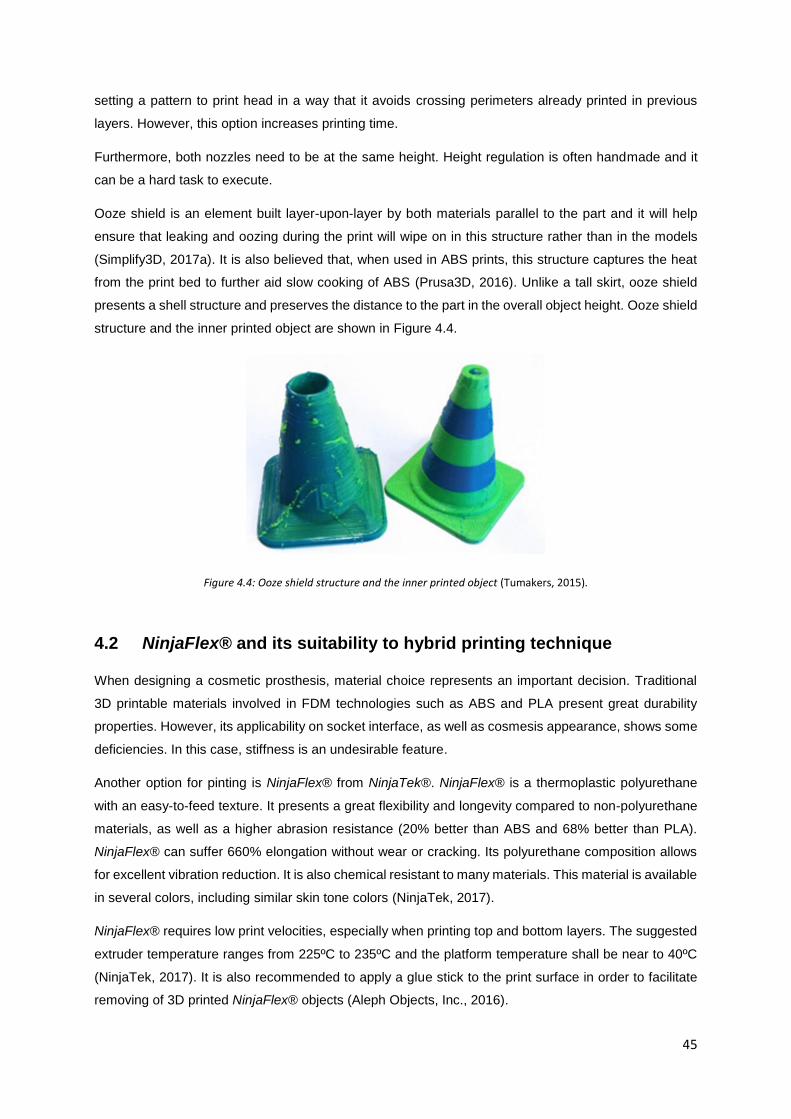
45
setting a pattern to print head in a way that it avoids crossing perimeters already printed in previous
layers. However, this option increases printing time.
Furthermore, both nozzles need to be at the same height. Height regulation is often handmade and it
can be a hard task to execute.
Ooze shield is an element built layer-upon-layer by both materials parallel to the part and it will help
ensure that leaking and oozing during the print will wipe on in this structure rather than in the models
(Simplify3D, 2017a). It is also believed that, when used in ABS prints, this structure captures the heat
from the print bed to further aid slow cooking of ABS (Prusa3D, 2016). Unlike a tall skirt, ooze shield
presents a shell structure and preserves the distance to the part in the overall object height. Ooze shield
structure and the inner printed object are shown in Figure 4.4.
Figure 4.4: Ooze shield structure and the inner printed object (Tumakers, 2015).
4.2 NinjaFlex® and its suitability to hybrid printing technique
When designing a cosmetic prosthesis, material choice represents an important decision. Traditional
3D printable materials involved in FDM technologies such as ABS and PLA present great durability
properties. However, its applicability on socket interface, as well as cosmesis appearance, shows some
deficiencies. In this case, stiffness is an undesirable feature.
Another option for pinting is NinjaFlex® from NinjaTek®. NinjaFlex® is a thermoplastic polyurethane
with an easy-to-feed texture. It presents a great flexibility and longevity compared to non-polyurethane
materials, as well as a higher abrasion resistance (20% better than ABS and 68% better than PLA).
NinjaFlex® can suffer 660% elongation without wear or cracking. Its polyurethane composition allows
for excellent vibration reduction. It is also chemical resistant to many materials. This material is available
in several colors, including similar skin tone colors (NinjaTek, 2017).
NinjaFlex® requires low print velocities, especially when printing top and bottom layers. The suggested
extruder temperature ranges from 225ºC to 235ºC and the platform temperature shall be near to 40ºC
(NinjaTek, 2017). It is also recommended to apply a glue stick to the print surface in order to facilitate
removing of 3D printed NinjaFlex® objects (Aleph Objects, Inc., 2016).

46
When using Lulzbot TAZ 3D printers, NinjaFlex® is only printable with a special head extruder, namely
Flexystruder or FlexyDually Tool Head. (Aleph Objects, Inc., 2016).
4.3 Print specifications
In the beginning of this work, the dual extruder had not arrived yet. Due to NinjaFlex® and FlexyDually
Tool Head unavailability, cosmetic prosthesis geometry was produced in white PLA. For that, Cura 21.03
Lulzbot Edition software was used to prepare the file for printing.
Applied print specifications are shown in Table 4.1. Due to object’s shape, Cura highlighted the need of
use support structures.
Table 4.1: Print specifications use for PLA print.
Print Parameters Value
Quality
Layer height (mm) 0.1
Shell thickness (mm) 0.8
Enable retraction On
Fill
Bottom/Top thickness (mm) 0.6
Fill Density (%) 50
Perimeters before Infill On
Speed and Temperature
Print speed (mm/s) 40
Printing temperature (C) 210
Bed temperature (C) 70
Support
Support type Touching buildplate
Platform adhesion type Brim
The remaining print features used were the default ones for a simple extrusion. The print took 17 hours
and 40 minutes and used 9.43 meters/75 grams of PLA. However, some of this amount of material was
used to print support structures. So, the final weight of the device is lower than this value.
Printing process and its final result are shown in Figure 4.5:.

47
Figure 4.5: PLA printing: A: Printing process; B: final print result .
Once the geometry printed, supports were removed with the aid of a paper knife. After that, the object
suffered some polish with grindstones and sandpaper. The final result is presented on Figure 4.6.
Figure 4.6: Final result after support removal and polish.
Once NinjaFlex® and FlexyDually Tool Head was available, efforts were concentrated on obtaining
prostheses prototypes produced in this material.
At first, NinjaFlex® was used together with ABS due to its ability to bind to this material (Aleph Objects,
Inc., 2016). In this way, ABS was used to produce support structures.
Slicing procedure was made with Cura 21.03 for Lulzbot. The features applied were the suggested one
for dual extrusion of NinjaFlex® and ABS by Lulzbot (Aleph Objects, 2016b).
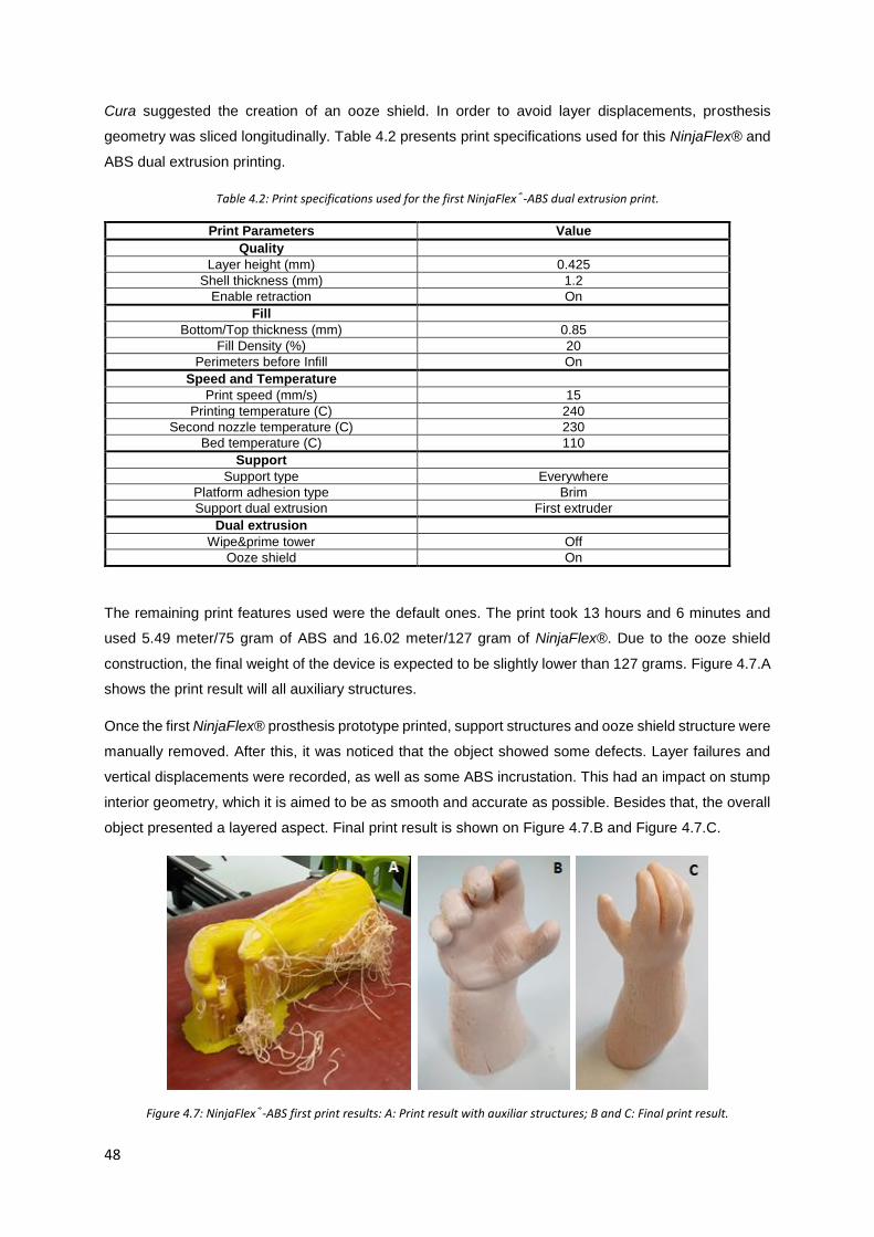
48
Cura suggested the creation of an ooze shield. In order to avoid layer displacements, prosthesis
geometry was sliced longitudinally. Table 4.2 presents print specifications used for this NinjaFlex® and
ABS dual extrusion printing.
Table 4.2: Print specifications used for the first NinjaFlex®-ABS dual extrusion print.
Print Parameters Value
Quality
Layer height (mm) 0.425
Shell thickness (mm) 1.2
Enable retraction On
Fill
Bottom/Top thickness (mm) 0.85
Fill Density (%) 20
Perimeters before Infill On
Speed and Temperature
Print speed (mm/s) 15
Printing temperature (C) 240
Second nozzle temperature (C) 230
Bed temperature (C) 110
Support
Support type Everywhere
Platform adhesion type Brim
Support dual extrusion First extruder
Dual extrusion
Wipe&prime tower Off
Ooze shield On
The remaining print features used were the default ones. The print took 13 hours and 6 minutes and
used 5.49 meter/75 gram of ABS and 16.02 meter/127 gram of NinjaFlex®. Due to the ooze shield
construction, the final weight of the device is expected to be slightly lower than 127 grams. Figure 4.7.A
shows the print result will all auxiliary structures.
Once the first NinjaFlex® prosthesis prototype printed, support structures and ooze shield structure were
manually removed. After this, it was noticed that the object showed some defects. Layer failures and
vertical displacements were recorded, as well as some ABS incrustation. This had an impact on stump
interior geometry, which it is aimed to be as smooth and accurate as possible. Besides that, the overall
object presented a layered aspect. Final print result is shown on Figure 4.7.B and Figure 4.7.C.
Figure 4.7: NinjaFlex®-ABS first print results: A: Print result with auxiliar structures; B and C: Final print result.

49
In order to improve results, a new print was performed. However, several features related to print
configuration were changed on Cura 21.03 profile. To decrease layered appearance, layer height
parameter was reduced to 0.2 mm. On the other hand, the geometry was now sliced transversally. With
this orientation, it is aimed to obtain a better stump interior profile. Table 4.3 presents print specifications
used for the second NinjaFlex® and ABS dual extrusion printing.
Table 4.3: Print specifications used for the second NinjaFlex®-ABS dual extrusion print.
Print Parameters Value Print Parameters Value
Basic Advanced
Quality Retraction
Layer height (mm) 0.2 Speed (mm/s) 10
Shell thickness (mm) 1.2 Distance (mm) 5
Enable retraction On Dual extrusion switch
amount (mm) 30
Fill Quality
Bottom/Top thickness (mm) 0.85 Initial layer thickness
(mm) 0.6
Fill Density (%) 20 Initial layer line width
(%) 125
Perimeters before Infill On Dual extrusion overlap (mm)
0.15
Speed and Temperature Speed
Print speed (mm/s) 15 Travel speed (mm/s) 175
Printing temperature (C) 240 Bottom layer speed 10
Second nozzle temperature (C)
230 Infill speed (mm/s) 12
Bed temperature (C) 110 Top/bottom speed
(mm/s) 12
Support Outer shell speed
(mm/s) 10
Support type Touching buildplate Inner shell speed
(mm/s) 12
Platform adhesion type Brim Cool
Support dual extrusion First extruder Minimal layer time
(sec) 10
Dual extrusion Enable cooling fan On
Wipe&prime tower Off
Ooze shield On

50
The remaining print features used were the default ones. The print took 26 hours and 21 minutes and
used 16.05 meter/127 gram of NinjaFlex® and 4.92 meter/39 gram of ABS.
Figure 4.8.A presents the printed prototype with its auxiliary structures. Stump interior geometry
presented better results. However, the object showed even more ABS incrustations. Besides that, finger
region exhibited more imperfections than the remaining regions of the object. Figure 4.8.B and Figure
4.8.C present final print results, where the referred imperfections can be seen.
Figure 4.8: Second NinjaFlex®-ABS print results: a) Print result with auxiliar structures; b) and c) Final print result.
The device was weighed and presented a weight of 115.25 gram. This value is lower than the amount
of NinjaFlex® material used to print the object. As aforesaid, this was expected due to ooze shield
construction.
Considering these results, a new print was performed. All parameters were maintained, except layer
height, which was decreased to 0.1 mm. Print parameters are summarized in Table 4.4.
Table 4.4: Print specifications used for the third NinjaFlex®-ABS dual extrusion print.
Print Parameters Value Print Parameters Value
Basic Advanced

51
Quality Retraction
Layer height (mm) 0.1 Speed (mm/s) 10
Shell thickness (mm) 1.2 Distance (mm) 5
Enable retraction On Dual extrusion switch amount (mm)
30
Fill Quality
Bottom/Top thickness (mm) 0.85 Initial layer thickness (mm)
0.6
Fill Density (%) 20 Initial layer line width (%)
125
Perimeters before Infill On Dual extrusion overlap (mm)
0.15
Speed and Temperature Speed
Print speed (mm/s) 15 Travel speed (mm/s) 175
Printing temperature (C) 240 Bottom layer speed 15
Second nozzle temperature (C)
230 Infill speed (mm/s) 18
Bed temperature (C) 110 Top/bottom speed (mm/s)
18
Support Outer shell speed (mm/s)
15
Support type Touching buildplate Inner shell speed (mm/s)
18
Platform adhesion type Brim Cool
Support dual extrusion First extruder Minimal layer time (sec)
10
Dual extrusion Enable cooling fan On
Wipe&prime tower Off
Ooze shield On
The expected print time was near to 41 hours. The print used 16.06 meters/127 grams of NinjaFlex®
and 4.93 meters/39 grams of ABS as well. The result presented also some ABS incrustations. With the
aid of a portion of acetone and a paperknife, it was sought to remove the incrustations. However,
acetone reacted with NinjaFlex® and its layers stretched in some regions. Finger quality wasn’t
improved and the overall prosthesis showed a dull aspect, maybe due for the low layer height. Final
print result is shown in Figure 4.9.
Figure 4.9: Final print result of the third NinjaFlex®-ABS print.
In order to solve ABS incrustations problem, a print without ABS was conducted. In this way, support
structures were made of NinjaFlex®. Slicing was made in the transverse direction, but print started from
distal portion of the prosthetic forearm. Print parameters are presented in Table 4.5
Table 4.5: Print specifications used for the NinjaFlex® support structures print.
Print Parameters Value Print Parameters Value
Basic Advanced

52
Quality Retraction
Layer height (mm) 0.1 Speed (mm/s) 10
Shell thickness (mm) 1.5 Distance (mm) 3
Enable retraction On Dual extrusion switch amount (mm)
30
Fill Quality
Bottom/Top thickness (mm) 2.1 Initial layer thickness (mm)
0.4
Fill Density (%) 20 Initial layer line width (%)
100
Perimeters before Infill On Dual extrusion overlap (mm)
0.2
Speed and Temperature Speed
Print speed (mm/s) 12 Travel speed (mm/s) 175
Printing temperature (C) 240 Bottom layer speed 10
Second nozzle temperature (C)
230 Infill speed (mm/s) 12
Bed temperature (C) 110 Top/bottom speed (mm/s)
12
Support Outer shell speed (mm/s)
10
Support type Everywhere Inner shell speed (mm/s)
12
Platform adhesion type Brim Cool
Support dual extrusion First extruder Minimal layer time (sec)
10
Dual extrusion Enable cooling fan On
Wipe&prime tower Off
Ooze shield On
Nevertheless, this material revealed too flexible to perform support functions. Print was forced to stop
in the middle of the process and the printed object revealed a poor quality, as it is shown in Figure 4.10.
Figure 4.10: Final result of the print with NinjaFlex® support structures.
Due to all of the difficulties, a new slicing software was used. Slic3r 1.2.9 is a slicing tool with a wide
feature range that allow a high personalized print. Slic3r needs to be integrated with the Repetier Host
software V1.6.2. This software connects the computer to the printer.
Several tests were performed with Slic3r, but only with a hand portion. One of the main print changes
was the use of a skirt structure instead of an ooze shield one. Unlike Cura, Slic3r allows to edit distance

53
between printed object and skirt. The referred distance was increased comparing to the ooze shield-
object distance in Cura slicing. These structures are described in the first section of this chapter. Besides
that, an “avoid crossing perimeters” option was activated. NinjaFlex® retraction when its extruder is
disabled was activated. Print velocities, namely outer perimeters velocities, were also reduced. Hand
portion was sliced in the transverse direction.
Avoid crossing perimeters and skirt increased distance revealed to be great features to use in dual
extrusion prints, due to incrustations reduction. However, ABS support structures were hard to remove
and some residues of this material were impossible to detach from the printed object, as shown in Figure
4.11.
Figure 4.11: ABS support structures residues on a NinjaFlex® object.
Due to the impossibility of eradicate all of ABS incrustations, as well as the difficulty in removing support
structures, PVA was used in the following prints instead of ABS.
Six different tests were performed with Slic3r. Detailed feature information is presented on the Appendix
A of this thesis. However, during the first four prints, the second extruder (the one that extrudes
NinjaFlex®) clogged with PVA already printed and laid on the platform. This occurred possibly due to
the different melting point of both materials. In this way, the second extruder was at a higher temperature
than PVA melting point and when it crosses PVA printed areas, some pieces are melted by the extruder
and attach to it. During these four performed tests, extruder temperature was down 20°C when the tool
was disabled, the second extruder was slightly lift in relation to the first and filament retraction was
reduced.
At the sixth test, the skirt structure was removed and the distance between support material and printed
object was increased to 0.2 mm. With these changes, the second extruder didn’t clog and the print was
completed.
However, due to the high computation weight of the geometry, Slic3r wasn’t able to process the
prosthesis file in an adequate time. For this, Cura was used to perform this task. The parameters applied
to print the device with support structures made of PVA are shown in Table 4.6.

54
Table 4.6: Print specifications used for the third NinjaFlex®-PVA dual extrusion print.
Print Parameters Value Print Parameters Value
Basic Advanced
Quality Retraction
Layer height (mm) 0.2 Speed (mm/s) 15
Shell thickness (mm) 1 Distance (mm) 0
Enable retraction On Dual extrusion switch amount (mm)
3
Fill Quality
Bottom/Top thickness (mm) 1.2 Initial layer thickness (mm)
0.0
Fill Density (%) 20 Initial layer line width (%)
100
Perimeters before Infill On Dual extrusion overlap (mm)
0.2
Speed and Temperature Speed
Print speed (mm/s) 30 Travel speed (mm/s) 120
Printing temperature (C) 190 Bottom layer speed 12
Second nozzle temperature (C)
245 Infill speed (mm/s) 20
Bed temperature (C) 30 Top/bottom speed (mm/s)
8
Support Outer shell speed (mm/s)
8
Support type Everywhere Inner shell speed (mm/s)
10
Platform adhesion type Brim Cool
Support dual extrusion First extruder Minimal layer time (sec)
10
Dual extrusion Enable cooling fan On
Wipe&prime tower Off
Ooze shield On
Once the object printed, ooze shield was manually removed and support structures were dissolved in
water. Incrustations problem was, in fact, solved with the use of PVA to build support structures.
However, some layers were printed with some horizontal misalignments and the support structures
damaged the surface of the object. Furthermore, after support dissolution, NinjaFlex® layers presented
some modifications, which affected the overall object appearance and structure. Final print result is
shown in Figure 4.9.

55
Figure 4.12: Final print result of NinjaFlex®-PVA print.
PVA-NinjaFlex® print took an average of 35 hours. It used 13.74 meter (109 gram) of PVA and 17.21
meter (136 gram) of NinjaFlex®.
All this prints were enough to conclude that print with NinjaFlex® is a hard task. However, some printer
settings can be modified in order to improve print results. Very slow prints (in the order of 8mm/s)
improve adhesion to the bed or to the previous layer. Retracting the filament when its extruder is disabled
also decreases material drool. In order to catch these drools, ooze shield and tall skirt also seemed to
be helpful strategies. However, when tall skirts are built by rigid materials, extruders can clash and break
the structure. Extruder cleansing plays a role in improving layer quality. When the extruder is dirt and
partially clogged, extruded filament isn’t consistent among all its length, which affects printed layer and,
later, the overall printed object.
Besides that, it was possible to confirm that NinjaFlex® adheres to ABS. However, when used to print
support structures, they can be hard to detach from the printed object. It was also observed that water
also interferes with NinjaFlex® properties.
4.4 Production Costs
To calculate production costs, it is important to know the average price of each material. In this way, 1
kg of conventional materials as ABS and PLA costs 38.40 € and 5.58 €, respectively. On the other hand,
PVA and NinjaFlex® costs are higher. 0.5 kg of natural PVA costs 31.24€ and 0.75 kg of NinjaFlex®
costs 58.08 € (Aleph Objects, 2016a).
In this way, since PLA prosthesis print used 75 grams of material, the average print cost of the device
is 0.42 €. However, this print was made before mesh scale up. With the current mesh dimension, a PLA
print with Cura default parameters would use 12.41 meter (98 gram) of material. In this way, this portion
of material would cost 0.55 €.
NinjaFlex®-ABS prints used 127 grams of NinjaFlex® and 39 grams of ABS. For this, NinjaFlex® used
portion costed 9.83 € and ABS portion costed 1.50 €. Final print cost of the device is 11.33 €, if printed
with these two materials.

56
On the other hand, NinjaFlex®-PVA print used 136 grams of NinjaFlex® and 109 grams of PVA.
NinjaFlex® used portion costed 10.53 € and PVA portion costed 6.81 €. Final print cost of the device is
11.34 €, if printed with these two materials.
Regarding the computational work required to build the device from the limb geometries acquisition until
the CAD definition, it is expected that a professional with experience in the field will need near to 20
hours of work to perform all the tasks suggested in the methodology. Acquisition steps are expected to
take 5 hours. After that, geometries process and CAM will take near to 6 hours of work. Tests with the
user take near to 1 hour. CAD prosthesis construction is expected to take 8 hours. Once this step
performed, the time needed to produce the device will depend on the settings defined in the slicing
software. However, as shown in Section 4.4, a proper AM production will need at least 17 hours. In the
end, the overall procedure to define a cosmetic prosthesis will this methodology takes at least 37 hours.
Cost-wise, considering that the hand-labour is payed at €20/hour, prosthesis labor costs €740.
For that, the final price of the device would be around €750. Additional costs related to features as the
suspension to the limb weren’t considered. However, these low costs present an advantage regarding
current prosthetic solutions available in the market.

57
Chapter 5
Concept generation for body-powered
prostheses
During upper limb disabled children growth, more complex prostheses are needed in order to improve
their daily living tasks. Once built the cosmetic prosthesis, it is time to think about the conception of a
body-powered device. For this, this chapter highlights the concept of 3D printable body powered upper
limb devices. It starts with a detailed state of the art and it ends with the suggestion of a possible solution
for the young child addressed in this work.
5.1 State of the art of 3D printable body-powered upper limb devices
A body-powered prosthesis is a device in which the person uses his or her own muscular power to
operate it. Open and closing the device can be done at different anatomical levels, usually depending
on the type of disability. In this way, transradial amputees can operate body-powered prosthesis with a
glenohumeral flexion (forward motion of the upper arm about the shoulder) or a biscapular abduction
(rounding the shoulders). A combination of both movements is the most common mode of operating
these devices. Transhumeral amputees in turn can be adapted with prosthesis powered by
glenohumeral flexion, biscapular abduction and shoulder depression followed by glenohumeral
extension (Kutz, 2004). Figure 5.1 illustrates the referred movements.
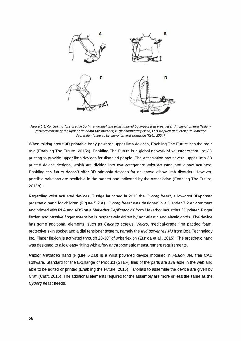
58
Figure 5.1: Control motions used in both transradial and transhumeral body-powered prostheses: A: glenohumeral flexion-forward motion of the upper arm about the shoulder; B: glenohumeral flexion; C: Biscapular abduction; D: Shoulder
depression followed by glenohumeral extension (Kutz, 2004).
When talking about 3D printable body-powered upper limb devices, Enabling The Future has the main
role (Enabling The Future, 2015c). Enabling The Future is a global network of volunteers that use 3D
printing to provide upper limb devices for disabled people. The association has several upper limb 3D
printed device designs, which are divided into two categories: wrist actuated and elbow actuated.
Enabling the future doesn’t offer 3D printable devices for an above elbow limb disorder. However,
possible solutions are available in the market and indicated by the association (Enabling The Future,
2015h).
Regarding wrist actuated devices, Zuniga launched in 2015 the Cyborg beast, a low-cost 3D-printed
prosthetic hand for children (Figure 5.2.A). Cyborg beast was designed in a Blender 7.2 environment
and printed with PLA and ABS on a Makerbot Replicator 2X from Makerbot Industries 3D printer. Finger
flexion and passive finger extension is respectively driven by non-elastic and elastic cords. The device
has some additional elements, such as Chicago screws, Velcro, medical-grade firm padded foam,
protective skin socket and a dial tensioner system, namely the Mid power rell M3 from Boa Technology
Inc. Finger flexion is activated through 20-30º of wrist flexion (Zuniga et al., 2015). The prosthetic hand
was designed to allow easy fitting with a few anthropometric measurement requirements.
Raptor Reloaded hand (Figure 5.2.B) is a wrist powered device modeled in Fusion 360 free CAD
software. Standard for the Exchange of Product (STEP) files of the parts are available in the web and
able to be edited or printed (Enabling the Future, 2015). Tutorials to assemble the device are given by
Craft (Craft, 2015). The additional elements required for the assembly are more or less the same as the
Cyborg beast needs.

59
Figure 5.2: A: Cyborg beast (Zuniga et al., 2015) B: Raptor Reloaded (Enabling the Future, 2015).
The Talon Hand (Figure 5.3) is presented by Enabling The Future as its most durable hand device and
with a greatest grip strength, which is great to play a wide range of sports. However, it has a challenging
and time-consuming assembly procedure. Files are available to be downloaded and printed. There are
available two different versions for the fingers part. Additional materials required for the assembly are a
leader piece, screws, elastic and non-elastic cords, hot glue, padded foam and plastic dip (Enabling The
Future, 2015f). Assembly tutorials are available in (e-NABLE, 2014).
Figure 5.3: Talon hand (Enabling The Future, 2015f).
The Odysseus Hand (Figure 5.4.A and B) was developed for young children. This device only has three
fingers in order to reduce the force necessary for grasping. When the wrist is flexed, small finger touches
the palm, as shown in Figure 5.4.B). Thumb and index fingers flexion creates a gripper shape. Shot
blunt fingers reduce the chance of self-hurting (profbink, 2014a). Its tensioning system and assembly
are very similar to the Talon Hand. Assembly tutorial is given by profbink (profbink, 2014b).
The Flexy Hand by Gyrobot (Figure 5.4.C) is a 3D printable prosthetic device made using flexible hinges.
Hinges are made of a flexible filament and, in that way, no elastic cords are necessary to return the
fingers to their outstretched position. With this, a frictionless articulation is achieved, as well as an
adaptive grip on irregular objects. Besides, the device can be used with a surgical glove to a more
realistic appearance. This device is fully printable and it doesn’t require additional elements for the
assembly (Krassenstein, 2014). The Flexy Hand 2 presents some upgrades, namely the gauntlet
attachment via Filaflex, a flexible 3D printable material (Recreus 3D Printing Materials, 2015), hinges, a

60
more realistic designed and a discrete glove attachment channels with Chicago screws. A Velcro style
glove attachment is suggested to fit the device to the stump.
Figure 5.4: A and B: Odysseus Hand (profbink, 2014a); C: Flexy Hand (Krassenstein, 2014).
Osprey Hand (Figure 5.5) is an edited version of the original Raptor Hand, based on the low-poly interior
and its robust components. It is suitable for sports due to its high durability and comfortable universal-
fit bracer (Enabling The Future, 2015d). It requires non-elastic cords for the assembly, but neither elastic
cords nor springs nor any mechanical extension system are needed. The inexistence of the elastic cords
improves the grasp of small objects. Assembly tutorials are given by Binkley (Binkley, 2015).
Figure 5.5: Osprey Hand (Enabling The Future, 2015d).
Falcon Hand V1, shown in Figure 5.6, was the first Enabling The Future 3D printed prototype to use
orthodontic rubber bands instead of the elastic cords that current devices use (B-town, 2016a). Acetone,
a small file, bead wire, Chicago screws and Velcro straps are also needed to the assembly. Phalanges
joints are assembled with small segments of printable filament and the referred rubber bands. Besides
that, this device allows radial and ulnar deviation movements, which as an inward rotation to the side
that the thumb is on and an outward rotation to the opposite side of the thumb. The assembly process
may have some hard features due to this last characteristic. However, a complete assembly guide is
provided.

61
Figure 5.6: Falcon Hand (B-town, 2016b).
The Phoenix Hand is available in four different versions: The original Phoenix Hand, Phoenix v2,
Unlimbited Phoenix and Phoenix Reborn (Enabling The Future, 2015e).
Original Phoenix Hand (Figure 5.7.A) is an adaptation of Falcon Hand v1 and Raptor Reloaded Hand.
As Falcon Hand v1, Phoenix hands uses orthodontic rubber bands.
Phoenix 2 (Figure 5.7.B) presents some improvements relating to the original Phoenix Hand. The
gauntlet is now a thermoformed equivalent. In this way, this part becomes lighter, stronger, and easier
to fit to user’s forearm. Palm part is also associated to a thermoformable mesh instead of the traditional
Velcro system. Assembly guide is given by Diamond (Diamond, 2016) . Phalanges are assembled with
dental bands. These bands will pull the fingers and thumb into their neutral position. To the assembly,
is also required non-elastic cords and some screws to the whippletree system.
UnLimbited Phoenix Hand is considered as the easiest version to print and assemble. The device
includes a more comfortable reverse dovetail thermoformed gauntlet. Unlike the remaining Phoenix
Hand versions, palm mesh is already integrated directly into the palm.
Phoenix Reborn device (Figure 5.7.C) results from a collaboration between Enabling The Future Sierra
Leone and the Hong Kong Maker Club. Phoenix Reborn Hand is an adaptation of Phoenix Hand &
UnLimbited Arm suitable for the hot weather. In this way, all rubber bands of the Phoenix Hand were
eliminated and some adaptations were performed.

62
Figure 5.7: A: Phoenix Hand (Enabling The Future, 2015e) ; B: Phoenix 2 (Team UnLimbited, 2017); C: Phoenix Reborn (enablesierraleone, 2017).
Regarding elbow actuated designs, Enabling The Future owns two printable designs: the Team
UnLimbited Arm and the RIT Arm (Enabling The Future, 2015b).
The RIT Arm is a device suitable for people with an arm with an elbow but no wrist. It can be actuated
by bending the residual anatomical elbow or via a bowden cable connected to a shoulder harness
(Enabling The Future, 2015g). The device presents a whippletree mechanism and the elastic-cord
system is separated into knuckle and finger section in order to acquire adjustable finger closure rates.
The assembled prosthesis only weights 330 grams (Norris, 2015). This device is shown in Figure 5.8.
Figure 5.8: RIT arm (Enabling The Future, 2015g).
The Derek’s arm is a RIT arm adaptation with a longer forearm. This device requires more customization
than an Enabling The Future one because it is larger and subjected to greater forces. Greater forces
are due to arm-bending to hand-closing linkage. This imposes limits on the extent to which the arm can
be bent and it puts additional force on the forearm. Furthermore, stump geometry is needed to perform
a custom fit forearm cup (Enabling the Future, 2014). Derek’s arm is designed to be printed in ABS or

63
Nylon. Customization tips are available in (Schull, Jon; Mohiuddin, 2017). A forearm cup customization
made of NinjaFlex® and silicone is also suggested in (Gyrobot, 2014).
Team UnLimbited Arm consists on a different set of elbow powered devices. The UnLimbited Arm -
Isabella edition- was created for those who have a functional elbow and a considerable length amount
of forearm but no wrist or enough wrist/palm to operate a wrist powered device (Team UnLimbited,
2015a). It was designed to be printed in PLA to allow for easy thermoforming. It is suitable for ages
between four and seven and able to be scaled within the 100% - 130% range. Correct sizing of the
UnLimbited arm is calculated by comparison of four separate measurements. Sizing guide usage is
provided. Three of the required measurements are exemplified in Figure 5.9. The forth measurement is
the tricep diameter for the cuff fitting.
Figure 5.9: Measurements needed to produce Isabella edition prosthesis (Team UnLimbited, 2015a).
Hand parts are the same as the Phoenix hand. A quick demo and assembly guide is given by S. Davies
(S. Davies, 2015). Both tricep cuff and forearm parts are thermoformed. No additional screws are
needed for the assembly.
Limitations regarding proper sizing are associated to Isabella edition prosthesis. As children grow,
proportions of size between hand, forearm and upper arm change. Isabella edition arm is only able to
be scaled up or scaled down proportionally. For this, The UnLimbited arm v2.0 – Alfie Edition (Figure
5.10) emerged as the first fully parametric 3D printed arm (Team UnLimbited, 2015b).

64
Figure 5.10: UnLimbited arm v2.0-Alfie Edition (Team UnLimbited, 2016).
To produce a proper device, the maker only has to collect three measurements from the future user.
With these measurements, all files are generated automatically and provided as a single zip file, which
content is ready to be printed. Such measurements are shown in Figure 5.11. A measurement is
performed on the affected upper arm; B and C measurements are taken from the non-affected forearm
and hand, respectively (Team UnLimbited, 2016).
Figure 5.11: Measurements needed to produce Alfie edition prosthesis (Team UnLimbited, 2016).
The device is also suitable to be printed in PLA (Team UnLimbited, 2016). Assembly procedures are
the same as the previous UnLimbited Arm version.
In all of this devices, gel tips may be applied in the fingers to improve grip (B-town, 2016a).
Still regarding body powered devices, two types of prehensors are documented. Prehensor exhibits an
important prosthetic feature, for the reason that one of the main causes of body-powered prosthesis
abandonment is its limited function, especially when the user presents an intact contralateral hand. In
this way, body-powered devices can present a voluntary closing (VC) and voluntary opening (VO)
system. In a VC device, the user actively closes the device and a passive element (for example, a
spring) returns the prehensor to the default open state. On the other hand, a VO device is actively open

65
by the user and a passive spring returns the device to the default closed state (Berning, Cohick,
Johnson, Miller, & Sensinger, 2014).
VO, as shown in Figure 5.12.a), is the most used system in body-powered devices. VO presents the
advantage of after actively opening the fingers and positioning them around a certain object, the user
can relax the limb due to the grip force provided by the spring to hold the object. However, these devices
can´t generate more force than the supplied by the spring. In this way, the user needs to choose a spring
strength based on the maximum grip force that he might need. This means that the user must overcome
a larger than necessary spring force to open the device when manipulating lightweight objects and then
to expend unnecessary energy. Furthermore, if a certain object requires more grip force than the spring
provides, user cannot properly manage it. However, some VO prehensors have the possibility to adjust
spring tension, but only over a limited range forces (Berning et al., 2014).
In VC devices (Figure 5.12.b)), a spring is used to overcome friction and return the fingers to the open
state. VC system is the closest to natural hand prehension (Kutz, 2004) and it is often used by children
and by some adults as well. They allow grasp force control and, in that way, users only expend as much
energy as needed to hold a certain object. However, the user needs to keep the grip force while holding
the object, which causes fatigue. This can be avoided if the device has a clutch. This clutch needs to be
disengaged at the end of each movement and are often associated to wear out (Berning et al., 2014).
Figure 5.12: a) Voluntary opening and b) Voluntary closing terminal devices. (Berning et al., 2014).
A survey of 31 people was conducted by Berning about whether subjects preferred one prehensor or
the other for specific tasks (Berning et al., 2014). Berning stated that many subjects preferred the higher
grip strength provided by VC devices during heavy objects manipulation or when dropping the object
was nontrivial, such as when pouring water. However, when making tasks that involve simultaneous
movement of joints and in which the performance is not only concentrated on the prehensor, users often
prefer VO devices, due to grip force maintenance without requiring them to constantly supply it. Berning
also recorded that using the VC device was slightly faster (1.3 s) than using the VO one.

66
Figure 5.13 sums up the state of the art of 3D printable body-powered upper limb devices and prehensor
type.
Figure 5.13: 3D printable body-powered upper limb devices and prehensor type overview.
5.2 Suggestion of a 3D printable body-powered prosthesis for the child
of the presented case study
Once collected all the information about 3D printable devices, as well as the advantages and
disadvantages regarding VO and VC devices, now is time to define a future body-powered solution for
the child of this case study.
Since the child is going to transit from a cosmetic device, devoid from any kind of movement, to a body
powered one, the chosen device must be bent with the less effort needed. The solution that meets this
need is the Odysseus hand. Odysseus hand is the suggested Enabling The Future device for young
children. Detailed information about this prosthesis is presented on the first section of this chapter.
Body-powered upper limb
devices
3D printable
Design
Wrist actuated
PhoenixHand
The original Phoenix Hand
Phoenix V2
Umlimbited Phoenix
Phoenix Reborn
Raptor reloaded
Talon Hand
Odysseus Hand
Flexy Hand
Osprey Hand
Cyborg Beast
Elbow actuated
The RIT arm
The Derek's
arm
Team Unlimbited
Arm
The Unlimbited
Arm -Isabella edition
V2.0 - Alfie edition
Prehensortype
Voluntary Opening
(VO)
Voluntary Closing
(VC)

67
However, Odysseus hand is a wrist powered device and the child has no wrist to bend it. For that, an
elbow actuation system must be taken into account. This class of devices offers two main solutions.
Each one is dedicated to a different forearm length. Since the child of this case study owns a transradial
disability of the upper third, a Team Unlimbited Arm bending system seams the most suitable choice.
Regarding prehensor system, literature recommends the use of VC devices for children. In fact,
Odysseus hand is already a VC device.
In this way, a hybrid of Odysseus hand and Team Unlimbited arm is suggested as the first body-powered
device for the child of this case study. Concerning Team Unlimbited arm, it is expected that the geometry
must need to suffer a scale down due to the age of the child. For that, the chosen device of Team
Unlimbited arm was the v2.0 – Alfie edition due to the ease of scaling up and down.
A draft of the suggested solution is shown in Figure 5.14.
Figure 5.14: Draft of the suggested body-powered solution: A: side view; B: bottom view; C: top view.

68

69
Chapter 6
Conclusions and future work
6.1 Conclusions
In this work, an upper limb cosmetic prosthesis is conceived and developed for a case study of a two
years old child.
In order to frame upper limb prosthetic devices, a chapter of upper limb disabilities, as well as a section
about the historic evolution of limb prostheses, were provided.
A methodology is presented to design and conceive this type of devices. For that, innovative
technologies were used. 3D SCAN was used to acquire stump geometry and the traditional method of
application of plaster was avoided.
Opposite limb geometry was also acquired to conceive the prosthetic hand. This was done by means of
CT technology, due to the impossibility of acquiring the hand geometry with 3D SCAN. This geometry
will help to give a natural appearance to the cosmetic device. In fact, an MRI would be the best
technology to perform this task, due to inexistence of ionizing radiation during the acquisition. However,
MRI is more expensive than CT and the decision of performing a CT to acquire this geometry was also
taken by medical doctors. With this procedure it was possible to store a digital geometry of a child’s
hand for future cosmetic devices. In this way, when available such geometry, it is possible to skip
opposite limb geometry acquisition step. Furthermore, CAD softwares also allow to scale up or down
the referred geometry in order to adapt it to the child growth.
A set of CAD software was used to process data and to define the geometry of the device. A detailed
workflow with the purpose of each software was also defined and integrated into the methodology.
During this process, CT geometry data was sculpted to fit to stump geometry. This procedure took more
time than the expected due to the deformation of the forearm captured in the CT. In this way, it is
important to highlight that when performing a CT, it will be assured that the anatomical region to acquire
is placed in the desired final shape. Once this deformation avoided, some alignment algorithms (such
as volume minimization algorithms (Zachariah, Sorenson, & Sanders, 2005)) can be applied to align
stump and opposite limb geometries
The device was fabricated with RP techniques. At first, the prototype was printed in PLA and later
produced in NinjaFlex®. The first solution was polished and then fitted to the child. Some months after,
the second solution was tested by the user as well. Both devices were well accepted by the user. The
child wears the prosthesis every day and for more than 8 hours a day. This aspect is in part related to
the early fit of the user to a prosthetic device. In fact, child has been wearing a rudimentary prosthesis

70
since his first year of life. Moreover, it means that aspects as stump acquisition, socket design and
geometries alignment were well performed.
Furthermore, the child integrated both new devices (the PLA and NinjaFlex® ones) as a preponderant
aid in several tasks, such as play on a swing set, holding objects and so forth. This is possibly linked to
the flexed hand shape. Besides that, parents noticed that these devices are lighter than the previous
one, which met one of theirs concerns. In this way, it is possible to conclude that, with a proper polish
finish, PLA shows to be an alternative solution to rudimentary solutions. Regarding NinjaFlex® solution,
it is also feasible to conclude that this material is suitable to manufacture prosthetic devices.
A dual extrusion printing technology was used to produce the final prototype. At first, NinjaFlex® and
ABS were used to print the device and its support structures, respectively. However, ABS seemed hard
to detach from the printed object. Prototypes printed with these two materials also presented some
pieces of ABS in the middle of NinjaFlex® layers. For that, it was possible to conclude that, when the
final aspect plays a role in NinjaFlex® objects, ABS isn’t suitable to print its support structures. Later,
ABS was replaced by PVA to print supports. Its water solubility promoted an easy support removal.
However, the gap in melting points of NinjaFlex® and PVA (nearly 40 °𝐶) led to NinjaFlex® extruder
clog with some printing configurations. Besides that, NinjaFlex® properties suffered some modifications
after water contact, which affected the overall object.
RP techniques proved its suitability for the conception of these devices. However, dual extrusion
techniques still present some challenges. Default print parameters showed to be inappropriate to all
objects. It is expected that, for each geometry and printer, print parameters may need some
adjustments. Furthermore, NinjaFlex® introduced a great amount of difficulties due to its elastic
character. Its higher cost, associated to its recent introduction into the market, leads to a weaker
knowledge in the field about how to operate with this filament.
It is also possible to conclude that the proposed methodology is suitable to produce upper limb cosmetic
prostheses. There are no records of such a methodology for an upper limb cosmetic device entirely
produced with RP techniques. Furthermore, the process of using a geometry of a real child hand and,
in that way, the process of acquiring opposite limb geometry to use as prosthetic hand, represent an
innovation in contrast to the literature. This step gives a high personalization level to the final device,
with is a preponderant aspect in the prosthetic field. Besides that, the possibility of scale up or scale
down acquired geometries gives a preponderant advantage to the methodology, due to the possibility
of adapting the device to the child growth.
This work was presented on 7th National Congress of Biomechanics and awarded with an honor mention
for the Best Application Paper.

71
6.2 Future work
The areas for future work can be divided in 4 categories: CAD software, RP improvement, prosthetic
suspension to the limb and body-powered solutions.
This work was focused on the methodology developed to conceive upper limb cosmetic prosthesis. In
this way, there are some future work to do beyond the proposed methodology.
Opposite limb geometry acquisition was only performed due to the inexistence of digital geometries of
child hands. In this way, there is a need for digital data bases where these kind of geometries are
available in standard formats and ready to use in several CAD environments.
During CAD modifications, there were several switches between softwares due to limitations of these
programs. It would have been very helpful if some software allowed to do all the modifications, that is,
in an integrated way. Some softwares packages dedicated to prosthetics and orthotics are available in
the market, such as CANFIT from VORUM (Vorum Research Corp., 2017b) and RODIN4D NEO
(Rodin4D, 2016); however they seem to present some weaknesses that could make it impossible to
reach a high personalized device.
Regarding the production of the device with RP techniques, it is important to found which print
parameters improve cosmetic prosthesis appearance. Different printers may be used in order to explore
resolution influence, for instance. Elastic printable polymers such as FilaFlex and SemiFlex® can also
be tested to produce these devices. Support structures material choice needs to be redefined. Both ABS
and PVA revealed to be unsuitable to perform this task with an object printed in NinjaFlex® with such
an intricate geometry.
A different support system of the prosthesis to the upper limb needs to be defined. Current system may
cause some discomfort, especially during summer season. A socket in some silicon lines in the proximal
portion or a suction suspension system are some possible choices.
Furthermore, the work related to the body-powered solution suggested in the Chapter 5 needs to be
continued. At first, it is important to confirm if Odysseus hand and Unlimbited arm v2.0 are able to be
adapted to each other. Some CAD modifications are expected to be needed in order to adjust both
devices. Geometries scale down procedures are also included in these modifications. After that, RP
production will need to be studied. Best print parameters must be chosen according to both material and
printer used. Assembly procedures and materials can also be devised.

72
References
3D Printing for Beginners. (2016). What Material Should I Use For 3D Printing? | 3D Printing for Beginners. Retrieved May 10, 2017, from http://3dprintingforbeginners.com/filamentprimer/
3ders. (2011). 3ders.org - The history of 3D printer. Retrieved May 9, 2017, from http://www.3ders.org/3d-printing/3d-printing-history.html
3DPrinterPrices.net. (2017). Dual Extruder 3D Printers - What you need to know. Retrieved May 10, 2017, from http://www.3dprinterprices.net/dual-extruder-3d-printers-what-you-need-to-know/
Abu Osman, N. A., Spence, W. D., Solomonidis, S. E., Paul, J. P., & Weir, A. M. (2010). The patellar tendon bar! Is it a necessary feature? Medical Engineering and Physics, 32(7), 760–765. Retrieved from http://dx.doi.org/10.1016/j.medengphy.2010.04.020
Al-Fakih, E. A., Abu Osman, N. A., & Mahmad Adikan, F. R. (2016). Techniques for interface stress measurements within prosthetic sockets of transtibial amputees: A review of the past 50 years of research. Sensors (Switzerland), 16(1119).
Aleph Objects, Inc. (2016). NinjaFlex | Lulzbot. Retrieved May 9, 2017, from https://www.lulzbot.com/store/filament/ninjaflex
Aleph Objects, I. (2016a). Filament | LulzBot. Retrieved May 30, 2017, from https://www.lulzbot.com/store/filament
Aleph Objects, I. (2016b). TAZ 6 Cura Profiles | LulzBot. Retrieved May 12, 2017, from https://www.lulzbot.com/taz-6-cura-profiles
Alexander, M. A., & Matthews, D. J. (2015). Pediatric Rehabilitation: Principles and Practice. (K. P. Murphy, Ed.) (Fifth Edit). New York: Demos Medical.
Amazing AM, L. (2017). AM Basics | Additive Manufacturing (AM). Retrieved May 9, 2017, from http://additivemanufacturing.com/basics/
Apkon, S. (2004). Pediatric Limb Deficiencies. The Children’s Hospital Physical Medicine and Rehabilitation, 8(1).
Association of Children’s Prosthetic - Orthotic Clinics, A. (1966). Classification of Limb Malformations On The Basis Of Embryological Failures. Retrieved May 16, 2017, from http://www.acpoc.org/newsletters-and-journals/1966_03_001.asp
Atkins, Diane J.; Heard, Denise C. Y., Donovan, W. H. (1996). Epidemiologic Overview of Individuals with Upper-Limb Loss and Their Reported Research Priorities. Journal of Prosthetics and Orthotics, 8(1), 2–11.
B-town. (2016a). Falcon Hand V1: 14 Steps. Retrieved May 6, 2017, from http://www.instructables.com/id/Falcon-Hand-V1/
B-town. (2016b). Falcon Hand V1: 14 Steps. Retrieved May 31, 2017, from http://www.instructables.com/id/Falcon-Hand-V1/
Baronio, G., Harran, S., & Signoroni, A. (2016). A Critical Analysis of a Hand Orthosis Reverse Engineering and 3D Printing Process. Applied Bionics and Biomechanics, 2016.
Beaver, S. (2007). Running Head: Upper Limb deficiencies and Upper Extremity Amputations and the Lived Experiencies of these Individuals. American Journal of Occupational Therapy, 1–23.
Berning, K., Cohick, S., Johnson, R., Miller, L. A., & Sensinger, J. W. (2014). Comparison of body-powered voluntary opening and voluntary closing prehensor for activities of daily life. Journal of Rehabilitation Research and Development, 51(2), 253–262. Retrieved from http://www.rehab.research.va.gov/jour/2014/512/pdf/JRRD-2013-05-0123.pdf
Bibb, R., & Winder, J. (2010). A review of the issues surrounding three-dimensional computed tomography for medical modelling using rapid prototyping techniques. Radiography, 16(1), 78–

73
83. Retrieved from http://dx.doi.org/10.1016/j.radi.2009.10.005
Binkley, P. (2015). Osprey/Gamma Raptor: Removing Support Material from the Palm and Bracer - YouTube. Retrieved May 6, 2017, from https://www.youtube.com/watch?list=PLBHsuyNYSpxvS1EgMP67EszQwgE-Hqq5o&v=wiq6tWvyMc4
BioSculptor. (2017). BioSculptor Orthotic and Prosthetic CAD/CAM Systems. Retrieved April 29, 2017, from http://biosculptor.com/
Bonarrigo, F., Signoroni, A., & Botsch, M. (2014). Deformable registration using patch-wise shape matching. Graphical Models, 76(5), 554–565. Retrieved from http://dx.doi.org/10.1016/j.gmod.2014.04.004
Bosse, M. J., MacKenzie, E. J., Kellam, J. F., Burgess, A. R., Webb, L. X., Swiontkowski, Marc F. Sanders, R. W., … Castillo, R. C. (2002). An Analysis of Outcomes of Reconstruction or Amputation of Leg-Threatening Injuries. The New England Journal of Medicine, 347(24), 1924–1931.
Bowker HK, M. (2002). Atlas of Limb Prosthetics. Retrieved April 18, 2017, from http://www.oandplibrary.org/alp/
Brooks, Milo B.;Shaperman, J. (1965). Infant Prosthetic Fitting. American Journal of Occupational Therapy, XIX(6). Retrieved from http://www.acpoc.org/newsletters-and-journals/1966_11_016.asp
Centers for Disease Control and Prevention. (2016). Upper and Lower Limb Reduction Defects. Retrieved March 24, 2017, from https://www.cdc.gov/ncbddd/birthdefects/ul-limbreductiondefects.html#ref
Ceresana. (2017). Bioplastics - Study: Market, Analysis, Trends | Ceresana. Retrieved May 10, 2017, from http://www.ceresana.com/en/market-studies/plastics/bioplastics/
Childress, Dudley S.; Rovick, J. S. (1994). An additive fabrication technique for the CAM of prosthetic sockets. Journal of Rehabilitation Research and Development, 1, 30–31.
Chilson, L. (2013). The Difference Between ABS and PLA for 3D Printing - ProtoParadigm. Retrieved May 10, 2017, from http://www.protoparadigm.com/news-updates/the-difference-between-abs-and-pla-for-3d-printing/
Colombo, Giorgio; Bertetti, Massimiliano; Bonacini, Daniele; Magrassi, G. (2006). Reverse engineering and rapid prototyping techniques to innovate prosthesis socket design. Electronic …, 6056, 1–11. Retrieved from http://proceedings.spiedigitallibrary.org/proceeding.aspx?articleid=727813
Colombo, G., Facoetti, G., & Rizzi, C. (2013). A digital patient for computer-aided prosthesis design. Interface Focus, 3(2). Retrieved from http://www.pubmedcentral.nih.gov/articlerender.fcgi?artid=3638481&tool=pmcentrez&rendertype=abstract
Commean, P. K., Brunsden, B. S., Smith, K. E., & Vannier, M. W. (1998). Below-knee residual limb shape change measurement and visualization. Archives of Physical Medicine and Rehabilitation, 79(7), 772–782.
Commean, P. K., Smith, K. E., & Vannier, M. W. (1997). Lower extremity residual limb slippage within the prosthesis. Archives of Physical Medicine and Rehabilitation, 78(5), 476–485.
Comotti, C., Regazzoni, D., Rizzi, C., & Vitali, A. (2015). Multi-material design and 3D printing method of lower limb prosthetic sockets. In Proceedings of the 3rd 2015 Workshop on ICTs for improving Patients Rehabilitation Research Techniques - REHAB ’15 (pp. 42–45). https://doi.org/10.1145/2838944.2838955
Cordella, F., Ciancio, A. L., Sacchetti, R., Davalli, A., Cutti, A. G., Guglielmelli, E., & Zollo, L. (2016). Literature Review on Needs of Upper Limb Prosthesis Users. Frontiers in Neuroscience, 10(209).

74
Craft, C. (2015). Raptor Reloaded Assembly: Step 1 Laying out the parts - YouTube. Retrieved May 10, 2017, from https://www.youtube.com/watch?list=PLA7_By5ei42zmZThuTbNQOQCmkE4qloEA&v=piQgqobWXs8
CREAFORM. (2017). New features VXelements 2 | Creaform. Retrieved May 20, 2017, from https://www.creaform3d.com/en/new-features-vxelements
Cugini, U., Bertetti, M., Bonacini, D., Colombo, G., Corradini, C., & Magrassi, G. (2006). Innovative Implementation in Socket Design : Digital Models to Customize the Product. In Proceedings ArtAbilitation (pp. 54–61). Retrieved from http://www.google.com.my/#hl=en&tbo=d&sclient=psy-ab&q=innovative+implementation+in+socket+design:+digital+models+to+customize+the+product&oq=innovative+implementation+in+socket+design:+digital+models+to+customize+the+product&gs_l=hp.3...1107.32203.0.3280
Cummins, K. (2017). The rise of additive manufacturing | The Engineer. Retrieved May 9, 2017, from https://www.theengineer.co.uk/the-rise-of-additive-manufacturing/
Curran, B., & Hambrey, R. (1991). The prosthetic treatment of upper limb deficiency. Prosthetics and Orthotics International, 15(2), 82–87.
CustomPartNet. (2017). Fused Deposition Modeling (FDM). Retrieved May 9, 2017, from http://www.custompartnet.com/wu/fused-deposition-modeling
Davids, J. R., Wagner, L. V, Meyer, L. C., & Blackhurst, D. W. (2006). Prosthetic Management of Children with Unilateral Congenital Below-Elbow Deficiency. The Journal of Bone and Joint Surgery. American Volume, 88(6), 1294–1300. Retrieved from http://www.ncbi.nlm.nih.gov/pubmed/16757763
Davies, R. M., Lawrence, R. B., Routledge, P. E., & Knox, W. (1985). The Rapidform process for automated thermoplastic socket production. Prosthet Orthot Int, 9(1), 27–30. Retrieved from http://www.ncbi.nlm.nih.gov/pubmed/4000908%5Cnhttp://poi.sagepub.com/content/9/1/27.full.pdf
Davies, S. (2015). UnLimIted Arm Release - YouTube. Retrieved May 7, 2017, from https://www.youtube.com/watch?v=369PX9LzUPs
Day, H. J. B. (1991). The ISO/ISPO classification of congenital limb deficiency. Prosthetics and Orthotics International, 15, 67–69.
Diamond, J. (2016). Assembling the Phoenix hand Obtaining the STL files, (March).
Dimas, V., Kargel, J., Bauer, J., & Chang, P. (2007). Forequarter amputation for malignant tumours of the upper extremity: Case report, techniques and indications. The Canadian Journal of Plastic Surgery = Journal Canadien de Chirurgie Plastique, 15(2), 83–85. Retrieved from http://www.pubmedcentral.nih.gov/articlerender.fcgi?artid=2698809&tool=pmcentrez&rendertype=abstract
Direct Dimensions Inc. (2010). Direct Dimensions, Inc. Blog: Case Study: Using 3D Imaging to Create High-Res Prosthetic Hand. Retrieved April 29, 2017, from http://directdimensions.blogspot.pt/2010/01/case-study-using-3d-imaging-to-create.html
Douglas, T. S., Solomonidis, S. E., Lee, V. S., Spence, W. D., Sandham, W. a, & Hadley, D. M. (1998). Automatic segmentation of magnetic resonance images of the trans-femoral residual limb. Medical Engineering & Physics, 20(10), 756–763. https://doi.org/]
e-NABLE. (2014). e-NABLE Talon Hand 2.0 - Tutorial Part 1 - YouTube. Retrieved May 15, 2017, from https://www.youtube.com/watch?v=Ii_OYzhCcJg
Egermann, M., Kasten, P., & Thomsen, M. (2009). Myoelectric hand prostheses in very young children. International Orthopaedics, 33(4), 1101–1105.
enablesierraleone. (2017). Reborn Hand by enablesierraleone - Thingiverse. Retrieved May 16, 2017, from https://www.thingiverse.com/thing:2217431
Enabling the Future. (2014). 3D Printed e-NABLE Arms…MAGIC! – Enabling The Future. Retrieved May 8, 2017, from http://enablingthefuture.org/2014/06/25/3d-printed-e-nable-arms-magic/

75
Enabling the Future. (2015). The Raptor Reloaded – Enabling The Future. Retrieved May 5, 2017, from http://enablingthefuture.org/upper-limb-prosthetics/raptor-reloaded/
Enabling The Future. (2015a). ABOUT US – Enabling The Future. Retrieved May 19, 2017, from http://enablingthefuture.org/about/
Enabling The Future. (2015b). ELBOW POWERED – Enabling The Future. Retrieved May 7, 2017, from http://enablingthefuture.org/elbow-powered/
Enabling The Future. (2015c). Enabling The Future - A Global Network Of Passionate Volunteers Using 3D Printing To Give The World A “Helping Hand.” Retrieved May 15, 2017, from http://enablingthefuture.org/
Enabling The Future. (2015d). Osprey Hand – Enabling The Future. Retrieved May 6, 2017, from http://enablingthefuture.org/osprey-hand/
Enabling The Future. (2015e). Phoenix Hand – Enabling The Future. Retrieved May 6, 2017, from http://enablingthefuture.org/phoenix-hand/
Enabling The Future. (2015f). Talon Hand 2.X – Enabling The Future. Retrieved May 15, 2017, from http://enablingthefuture.org/upper-limb-prosthetics/talon-hand/
Enabling The Future. (2015g). The RIT Arm – Enabling The Future. Retrieved May 7, 2017, from http://enablingthefuture.org/upper-limb-prosthetics/rit-arm/
Enabling The Future. (2015h). WHICH DESIGN? – Enabling The Future. Retrieved April 20, 2017, from http://enablingthefuture.org/which-design/
EOS GmbH Co. (2015). Additive Manufacturing in the Medical Field [Brochure]. Retrieved from https://www.eos.info
Eshraghi, A., Osman, N. A. A., Gholizadeh, H., Ahmadian, J., Rahmati, B., & Abas, W. A. B. W. (2013). Development and evaluation of new coupling system for lower limb prostheses with acoustic alarm system. Scientific Reports, 3(2270), 1–5. Retrieved from http://www.nature.com/srep/2013/130724/srep02270/full/srep02270.html
Faulkner, Virgul W.; Walsh, N. E. (1989). Computer Designed Prosthetic Socket from Analysis of Computed Tomography Data. Journal of Prosthetics & Orthotics, 1(3), 154–164.
Faustini, M. C., Crawford, R. H., Neptune, R. R., Rogers, W. E., & Bosker, G. (2005). Design and analysis of orthogonally compliant features for local contact pressure relief in transtibial prostheses. Journal of Biomechanical Engineering, 127(November), 946–951.
Fernandes, A. A., Santos, A. R., & Silva, A. F. (2007). Projecto Integrado De Ajudas Técnicas Para Apoio À Locomoção – Desenvolvimento De Uma Ortótese Afo, 419–424.
Fernandes, J. F. M. (2016). Estudo da Influência de Parâmetros de Impressão 3D nas Propriedades Mecânicas do PLA Engenharia Mecânica Júri Outubro de 2016 Agradecimentos. University of Lisbon.
Fernie, G. R., Griggs, G., Bartlett, S., & Lunau, K. (1985). Shape sensing for computer aided below-knee prosthetic socket design. Prosthetics and Orthotics International, 9(1), 12–16.
Filabot. (2016). Smoothing ABS 3D Prints with Acetone – Filabot. Retrieved May 11, 2017, from https://www.filabot.com/blogs/news/85362052-smoothing-3d-abs-prints-with-acetone
Firth, H. (1997). Chorion villus sampling and limb deficiency--cause or coincidence? Prenatal Diagnosis, 17(13), 1313–1330. Retrieved from http://www.ncbi.nlm.nih.gov/pubmed/9509548
Frantz, C., & O’Rahilly, R. (1961). Congenital skeletal limb deficiencies. The Journal of Bone and Joint Surgery, 43–A(8), 1202–1224. Retrieved from http://jbjs.org/article.aspx?articleid=13601
Frillici, F. S., Rissone, P., Rizzi, C., & Rotini, F. (2008). The role of simulation tools to innovate the prosthesis socket design process. In Innovative Production Machines and Systems (pp. 214–219).

76
Gaebler-Spira, D., & Lipschutz, R. (2010). Pediatric Limb Deficiencies. Pediatric Rehabilitation: Principles and Practice.
Gold, N. B., Westgate, M. N., & Holmes, L. B. (2011). Anatomic and etiological classification of congenital limb deficiencies. American Journal of Medical Genetics, Part A, 155(6), 1225–1235.
Gonzalez, C. H., Marques-Dias, M. J., Kim, C. A., Sugayama, S. M. M., Da Paz, J. A., Huson, S. M., & Holmes, L. B. (1998). Congenital abnormalities in Brazilian children associated with misoprostol misuse in first trimester of pregnancy. Lancet, 351(9116), 1624–1627.
Green Prosthetics and Orthotics LLC. (2017). Upper Extremity Care | Green Prosthetics. Retrieved June 17, 2017, from http://www.greenprosthetics.com/areas-of-care/prosthetics-care-for-life/upper-extremity-care/
Gyrobot. (2014). Filaflex interface sock for e-NABLE - YouTube. Retrieved May 7, 2017, from https://www.youtube.com/watch?v=R-puEZoN1IM
Helbert, N., Simpson, D., Spence, W. D., & Ion, W. (2005). A preliminary investigation into the development of 3-D printing of prosthetic sockets. Journal of Rehabilitation Research and Development, 42(2), 141–146.
Henshaw, J. M., Wood, V., & Hall, A. C. (1999). Failure of automobile seat belts caused by polymer degradation. Engineering Failure Analysis, 6(1), 13–25.
ITK-Snap. (2014). HomePage. Retrieved May 24, 2017, from http://www.itksnap.org/pmwiki/pmwiki.php
Jain, S. (1996). Rehabilitation in Limb Deficiency . 2 . The Pediatric Amputee. Archives of Physical Medicine and Rehabilitation, 77(March), S-9-S-13.
Kai, C. C., Meng, C. S., Ching, L. S., Teik, L. S., & Aung, S. C. (2000). Facial prosthetic model fabrication using rapid prototyping tools. Integrated Manufacturing Systems, 11(1), 42–53.
Kay, H. W., & Newman, J. D. (1975). Relative incidences of new amputations: Statistical Comparisons of 6,000 New Amputees. Orthotics and Prosthetics, 29(2), 3–16.
Kerr, S. M., & McIntosh, J. B. (2000). Coping when a child has a disability: exploring the impact of parent-to-parent support. Child: Care, Health and Development, 26(4), 309–322.
Kooijman, C. M., Dijkstra, P. U., Geertzen, J. H. B., Elzinga, A., & Van Der Schans, C. P. (2000). Phantom pain and phantom sensations in upper limb amputees: An epidemiological study. Pain, 87(1), 33–41.
Krassenstein, E. (2014). The Flexy-Hand – The Most Innovative, Useful, Realistic Looking 3D Printed Prosthetic Hand Yet | 3DPrint.com | The Voice of 3D Printing / Additive Manufacturing. Retrieved May 6, 2017, from https://3dprint.com/1500/the-flexy-hand-3d-printed-prosthetic/
Kristinsson, O. (1993). The ICEROSS concept: a discussion of a philosophy. Prosthetics and Orthcubtics International, 17(1), 49–55.
Kutz, M. (2004). Design of Artificial Arms and Hands for Prosthetic Applications. In McGraw-Hill (Ed.), Standard Handbook of Biomedical Engineering and Design (p. 32.1-32.59).
Kuyper, M. a, Breedijk, M., Mulders, a H., Post, M. W., & Prevo, a J. (2001). Prosthetic management of children in the Netherlands with upper limb deficiencies. Prosthetics and Orthotics International, 25(3), 228–234.
Le, J. T., & Scott-Wyard, P. R. (2015). Pediatric Limb Differences and Amputations. Physical Medicine and Rehabilitation Clinics of North America, 26(1), 95–108. https://doi.org/10.1016/j.pmr.2014.09.006
LIM Innovations. (2017). Infinite Socket TF|LIM Innovations. Retrieved May 4, 2017, from https://www.liminnovations.com/products/infinite-socket/
Lombard, M. (2014). Design for 3D Printing - Siemens PLM Community - 23607. Retrieved May 15, 2017, from https://community.plm.automation.siemens.com/t5/Solid-Edge-Blog/Design-for-3D-

77
Printing/ba-p/23607
Lopes, D. S., Neptune, R. R., Gonçalves, A. A., Ambrósio, J. A., & Silva, M. T. (2015). Shape Analysis of the Femoral Head: A Comparative Study Between Spherical, (Super)Ellipsoidal, and (Super)Ovoidal Shapes. Journal of Biomechanical Engineering. Retrieved from http://biomechanical.asmedigitalcollection.asme.org/article.aspx?doi=10.1115/1.4031650
MacKenzie, E. J., Morris, Jr., J. A., Jurkovich, G. J., Yasui, T., Cushing, B. M., Burgess, A. R., … Swiontkowski, M. F. (1998). Return to work following injury: the role of economic, social, and job-related factors. American Journal of Public Health, 88(11), 1630–1637.
MakerBot Industries LLC. (2016). Dual Extrusion - Problems - Topics - Flashforge - Groups - Thingiverse. Retrieved May 13, 2017, from https://www.thingiverse.com/groups/flashforge/topic:9596
Mawale, M. B., Kuthe, A. M., & Dahake, S. W. (2016). Additive layered manufacturing: State-of-the-art applications in product innovation. Concurrent Engineering Research and Applications, 24(1), 94–102.
McGuirk, C. K., Westgate, M. N., & Holmes, L. B. (2001). Limb deficiencies in newborn infants. Pediatrics, 108(4), E64.
Meier, R. H. (2004). History of Arm Amputation, Prosthetic Restoration, and Arm Amputation Rehabilitation. (D. J. Atkins, Ed.), Functional Restoration of Adults and Children with Upper Extremity Amputation (Third Edit). New York: Demos Medical Publishing.
Minns, R. J., Bibb, R., Banks, R., & Sutton, R. A. (2003). The use of a reconstructed three-dimensional solid model from CT to aid the surgical management of a total knee arthroplasty: A case study. Medical Engineering and Physics, 25(6), 523–526.
Nagarajan, R., Neglia, J. P., Clohisy, D. R., & Robison, L. L. (2002). Limb salvage and amputation in survivors of pediatric lower-extremity bone tumors: What are the long-term implications? Journal of Clinical Oncology, 20(22), 4493–4501.
Nayak, Chitresh; Singh, Amit; Chaudhary, H. (2014). Customised prosthetic socket fabrication using 3D scanning and printing. In Additive Manufacturing Society of India.
NinjaTek. (2017). NinjaFlex Flexible 3D Printing Filament | NinjaTek. Retrieved May 10, 2017, from https://ninjatek.com/products/filaments/ninjaflex/
Norris, N. (2015). Arm v2 by masnart39 - Thingiverse. Retrieved May 7, 2017, from https://www.thingiverse.com/thing:1131463
Norton, K. (2007). A brief History of Prosthetics. InMotion, 17(7), 11–13. Retrieved from http://www.amputee-coalition.org/inmotion/nov_dec_07/history_prosthetics.html
Ottobock. (2016). MyolinoWrist 2000 | Myo Wrist Units and Rotation | Myo Hands and Components | Upper Limb Prosthetics | Prosthetics | Ottobock US Healthcare. Retrieved June 17, 2017, from https://professionals.ottobockus.com/Prosthetics/Upper-Limb-Prosthetics/Myo-Hands-and-Components/Myo-Wrist-Units-and-Rotation/MyolinoWrist-2000/p/10V51~52
Ovadia, S. A., & Askari, M. (2015). Upper Extremity Amputations and Prosthetics. Seminars in Plastic Surgery, 29(1), 55–61.
Pasquina, P. F., Bryant, P. R., Huang, M. E., Roberts, T. L., Nelson, V. S., & Flood, K. M. (2006). Advances in amputee care. Archives of Physical Medicine and Rehabilitation, 87(3 SUPPL 1), 34–43.
Paterson, A. M. J., Bibb, R. J., & Campbell, R. I. (2010). A review of existing anatomical data capture methods to support the mass customisation of wrist splints. Journal of Virtual and Physical Prototyping, 5(4), 201–207.
Pezzin, L. E., Dillingham, T. R., & MacKenzie, E. J. (2000). Rehabilitation and the long-term outcomes of persons with trauma-related amputations. Archives of Physical Medicine and Rehabilitation, 81(3), 292–300.

78
Pillet, J; Didierjean-Pillet, A. (2001). Aesthetic Hand Prosthesis: Gadget or Therapy? Presentation of a New Classification. The Journal of Hand Surgery: Journal of the British Society for Surgery of the Hand, 26(6), 523–528. Retrieved from http://jhs.sagepub.com/cgi/doi/10.1054/jhsb.2001.0658
Plastics International. (2017). ABS | Plastics International. Retrieved May 10, 2017, from http://www.plasticsintl.com/abs.htm
Postema, K., Donk, V. Van Der, Limbeek, J. Van, & Poelma, M. J. (1999). Prosthesis rejection in children with a unilateral congenital arm defect. Clinical Rehabilitation, 13(99), 243–249.
profbink. (2014a). Ody Hand 2.0 by profbink - Thingiverse. Retrieved May 6, 2017, from https://www.thingiverse.com/thing:262930
profbink. (2014b). Ody Hand Intro - YouTube. Retrieved May 6, 2017, from https://www.youtube.com/watch?v=gM8aV6coqEE
Pruitt, S. D., Seid, M., Varni, J. W., & Setoguchi, Y. (1999). Toddlers With Limb Deficiency: Conceptual Basis and initial Application of a Functional Status Outcome Measure. Archives of Physical Medicine and Rehabilitation, 80(7), 819–824.
Pruitt, S. D., Varni, J. W., & Setoguchi, Y. (1996). Functional status in children with limb deficiency: development and initial validation of an outcome measure. Archives of Physical Medicine and Rehabilitation, 77(April), 1233–1238.
Prusa3D. (2016). Will adding an ooze shield be benificial when printing with ABS? - Prusa Research. Retrieved May 14, 2017, from http://shop.prusa3d.com/forum/print-tips-slic3r-settings-kisslicer-model-repair--f12/will-adding-an-ooze-shield-be-benificial-when-prin-t2299.html
Prweb. (2010). Breakthrough Prosthetic Socket System Greatly Improves Comfort and Performance for Individuals with Limb Loss. Retrieved June 18, 2017, from http://www.prweb.com/releases/2010/08/prweb4414824.htm
Radcliffe, C. W. (1962). The Biomechanics of Below-Knee Prostheses in Normal , Level , Bipedal Walking. Artif Limbs, 6, 16–24.
Raichle, K. A., Hanley, M. A., Molton, I., Kadel, N. J., Campbell, K., Phelps, E., … Smith, D. G. (2008). Prosthesis use in persons with lower- and upper-limb amputation. The Journal of Rehabilitation Research and Development, 45(7), 961–972. Retrieved from http://www.rehab.research.va.gov/jour/08/45/7/pdf/raichle.pdf
Recreus 3D Printing Materials. (2015). About Filaflex - RecreusRecreus. Retrieved June 4, 2017, from https://recreus.com/blog/about-filaflex/?lang=en
Rengier, F., Mehndiratta, A., Von Tengg-Kobligk, H., Zechmann, C. M., Unterhinninghofen, R., Kauczor, H. U., & Giesel, F. L. (2010). 3D printing based on imaging data: review of medical applications. International Journal of Computer Assisted Radiology and Surgery, 5(4), 335–341.
Rodin4D. (2016). Rodin4D CAD/CAM solution for prosthetics and orthotics. Retrieved April 29, 2017, from http://www.scheckandsiress.com/products-services/prosthetic-advancements/
Rogers, B., Bosker, G. W., Crawford, R. H., Faustini, M. C., Neptune, R. R., Walden, G., & Gitter, A. J. (2007). Advanced trans-tibial socket fabrication using selective laser sintering. Prosthetics and Orthcubtics International, 31(1), 88–100. Retrieved from http://www.ncbi.nlm.nih.gov/pubmed/17365888
Rogers, B., Gitter, A., Bosker, G., Faustini, M., Lokhande, M., & Crawford, R. (2001). Clinical evaluation of prosthetic sockets manufactured by selective laser sintering. In 2001 Solid Freeform Fabrication Symposium Proceedings (pp. 505–512). Retrieved from http://utwired.utexas.edu/lff/symposium/proceedingsArchive/pubs/Manuscripts/2001/2001-57-Rogers.pdf
Rogers, B., Stephens, S., Gitter, A., Bosker, G., & Crawford, R. H. (2000). Double-wall, transtibial prosthetic socket fabricated using selective laser sintering: A case study. Journal of Prosthetics and Orthotics, 12(3), 97–103.
Rogers, W. E., Crawford, R. H., Beaman, J. J., & Walsh, N. E. (1991). Fabrication of Prosthetic
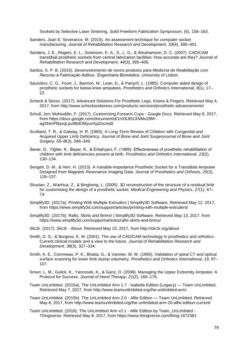
79
Sockets by Selective Laser Sintering. Solid Freeform Fabrication Symposium, (6), 158–163.
Sanders, Joan E; Severance, M. (2015). An assessment technique for computer-socket manufacturing. Journal of Rehabilitation Research and Development, 33(4), 395–401.
Sanders, J. E., Rogers, E. L., Sorenson, E. A., S., L. G., & Abrahamson, D. C. (2007). CAD/CAM transtibial prosthetic sockets from central fabrication facilities: How accurate are they? Journal of Rehabilitation Research and Development, 44(3), 395–406.
Santos, S. P. B. (2015). Desenvolvimento de novos produtos para Medicina de Reabilitação com Recurso à Fabricação Aditiva : Engenharia Biomédica. University of Lisbon.
Saunders, C. G., Foort, J., Bannon, M., Lean, D., & Panych, L. (1985). Computer aided design of prosthetic sockets for below-knee amputees. Prosthetics and Orthotics International, 9(1), 17–22.
Scheck & Siress. (2017). Advanced Solutions For Prosthetic Legs, Knees & Fingers. Retrieved May 4, 2017, from http://www.scheckandsiress.com/products-services/prosthetic-advancements/
Schull, Jon; Mohiuddin, F. (2017). Customizing Forearm Cups - Google Docs. Retrieved May 8, 2017, from https://docs.google.com/document/d/1nX6Jt51XNMu29M--agSNmPBqvqLpu98dOMyuvXja2xc/edit
Scotland, T. R., & Galway, H. R. (1983). A Long-Term Review of Children with Congenital and Acquired Upper Limb Deficiency. Journal of Bone and Joint Surgeryournal of Bone and Joint Surgery, 65–B(3), 346–349.
Sener, G., Yiğiter, K., Bayar, K., & Erbahçeci, F. (1999). Effectiveness of prosthetic rehabilitation of children with limb deficiencies present at birth. Prosthetics and Orthotics International, 23(2), 130–134.
Sengeh, D. M., & Herr, H. (2013). A Variable-Impedance Prosthetic Socket for a Transtibial Amputee Designed from Magnetic Resonance Imaging Data. Journal of Prosthetics and Orthosis, 25(3), 129–137.
Shuxian, Z., Wanhua, Z., & Bingheng, L. (2005). 3D reconstruction of the structure of a residual limb for customising the design of a prosthetic socket. Medical Engineering and Physics, 27(1), 67–74.
Simplify3D. (2017a). Printing With Multiple Extruders | Simplify3D Software. Retrieved May 12, 2017, from https://www.simplify3d.com/support/articles/printing-with-multiple-extruders/
Simplify3D. (2017b). Rafts, Skirts and Brims! | Simplify3D Software. Retrieved May 13, 2017, from https://www.simplify3d.com/support/articles/rafts-skirts-and-brims/
Slic3r. (2017). Slic3r - About. Retrieved May 10, 2017, from http://slic3r.org/about
Smith, D. G., & Burgess, E. M. (2001). The use of CAD/CAM technology in prosthetics and orthotics-Current clinical models and a view to the future. Journal of Rehabilitation Research and Development, 38(3), 327–334.
Smith, K. E., Commean, P. K., Bhatia, G., & Vannier, M. W. (1995). Validation of spiral CT and optical surface scanning for lower limb stump volumetry. Prosthetics and Orthotics International, 19, 97–107.
Smurr, L. M., Gulick, K., Yancosek, K., & Ganz, O. (2008). Managing the Upper Extremity Amputee: A Protocol for Success. Journal of Hand Therapy, 21(2), 160–176.
Team UnLimbited. (2015a). The UnLimbited Arm 1.7 - Isabella Edition (Legacy) — Team UnLimbited. Retrieved May 7, 2017, from http://www.teamunlimbited.org/the-unlimbited-arm/
Team UnLimbited. (2015b). The UnLimbited Arm 2.0 - Alfie Edition — Team UnLimbited. Retrieved May 8, 2017, from http://www.teamunlimbited.org/the-unlimbited-arm-20-alfie-edition-current/
Team UnLimbited. (2016). The UnLimbited Arm v2.1 - Alfie Edition by Team_UnLimbited - Thingiverse. Retrieved May 8, 2017, from https://www.thingiverse.com/thing:1672381

80
Team UnLimbited. (2017). Unlimbited Phoenix Hand by Team_UnLimbited - Thingiverse. Retrieved May 16, 2017, from https://www.thingiverse.com/thing:1674320
Tumakers. (2015). Tumaker no Twitter: “¿Sabéis que con la opción ”Ooze Shield“ las piezas de #Voladora #V2X2 os quedarán much más limpias? #Tumakertricks.” Retrieved May 14, 2017, from https://twitter.com/tumakers/status/552780083078119425
Upper Limb Prosthetics Information++. (2017). Upper Limb Prosthetics Information. Retrieved June 17, 2017, from http://www.upperlimbprosthetics.info/index.php?p=1_9_Body-Powered
Vannah, W., Drvaric, D., Stand, J., Hastings, J., Slocum, J., Harning, D., & Gorton, G. (1997). Performance of a Continuously Sampling Hand-Held Digitizer for Residual-Limb Shape Measurement. Journal of Prosthetics and Orthotics, 9(4), 157–162.
VirtualExpo Group. (2017a). Prótese de braço mioelétrica / multiarticulada / de adulto - Luke - DEKA Research. Retrieved May 18, 2017, from http://www.medicalexpo.com/pt/prod/deka-research/product-99342-647385.html
VirtualExpo Group. (2017b). Prótese de mão de controle motriz/ pinça-gancho/ de adulto - Nexo - Fillauer. Retrieved May 18, 2017, from http://www.medicalexpo.com/pt/prod/fillauer/product-74954-769447.html
VirtualExpo Group. (2017c). Prótese de mão de controle motriz/ pinça-gancho/ de adulto - Nexo - Fillauer.
VirtualExpo Group. (2017d). Prótese de mão de controle motriz / pinça-gancho / infantil - 12P - Fillauer. Retrieved May 18, 2017, from http://www.medicalexpo.com/pt/prod/fillauer/product-74954-466466.html
VirtualExpo Group. (2017e). Prótese de mão elétrica ativa / pinça-gancho / de adulto - Select - RSLSteeper. Retrieved May 30, 2017, from http://www.medicalexpo.com/pt/prod/rslsteeper/product-74956-458212.html#product-item_458446
VirtualExpo Group. (2017f). Prótese de mão mioelétrica/multiarticulada/de adulto - bebionic3 -RSLSteeper - Vídeos. Retrieved May 18, 2017, from http://www.medicalexpo.com/pt/prod/rslsteeper/product-74956-516672.html
VirtualExpo Group. (2017g). Prótese de mão mioelétrica / multiarticulada / de adulto - handii - exiii - Vídeos. Retrieved May 18, 2017, from http://www.medicalexpo.com/pt/prod/exiii/product-104325-711140.html
VirtualExpo Group. (2017h). Prótese de mão mioelétrica / pinça-gancho / de adulto - Aesthetic Prosthetics. Retrieved May 18, 2017, from http://www.medicalexpo.com/pt/prod/aesthetic-prosthetics/product-80496-507488.html
VirtualExpo Group. (2017i). Prótese parcial de mão mioelétrica / multiarticulada / de adulto - i-digits quantum - Touch Bionics - Vídeos. Retrieved May 16, 2017, from http://www.medicalexpo.com/pt/prod/touch-bionics/product-80664-794272.html
VirtualExpo Group. (2017j). Próteses de membros superiores: -Todos os fabricantes de equipamentos médicos - Vídeos. Retrieved May 18, 2017, from http://www.medicalexpo.com/pt/fabricante-medico/protese-membro-superior-29262.html
Vorum Research Corp. (2017a). CAD CAM Systems for Prosthetics and Orthotics. Retrieved April 29, 2017, from http://vorum.com/cad-cam-prosthetic-orthotic/
Vorum Research Corp. (2017b). Canfit 3D CAD Prosthetic and Orthotic Design Software. Retrieved May 5, 2017, from http://vorum.com/cad-cam-prosthetic-orthotic/canfit-design-software/
Walsh, N. E., Lancaster, J. L., Faulkner, V. W., & Rogers, W. E. (1989). A Computerized System to Manufacture Prostheses for Amputees in Developing Countries. Journal of Prosthetics & Orthotics, 1(3), 165–181.
Watson, S. (2000). The principles of management of congenital anomalies of the upper limb. Archives of Disease in Childhood, 83, 10–17.

81
WhiteClouds Inc. (2017). Kodama, Hideo and Photopolymer 3D Printing — whiteclouds 3D printing. Retrieved May 9, 2017, from https://www.whiteclouds.com/3dpedia-index/kodama-hideo-and-photopolymer-3d-printing
Wilcox, W. R., Coulter, C. P., & Schmitz, M. L. (2015). Congenital Limb Deficiency Disorders. Clinics in Perinatology, 42(2), 281–300. Retrieved from http://dx.doi.org/10.1016/j.clp.2015.02.004
Wittbrodt, B., & Pearce, J. M. (2015). The effects of PLA color on material properties of 3-D printed components. Additive Manufacturing, 8, 110–116. Retrieved from http://dx.doi.org/10.1016/j.addma.2015.09.006
Wu, C.-L., Chang, C.-H., Hsu, A.-T., Lin, C.-C., Chen, S.-I., & Chang, G.-L. (2003). A proposal for the pre-evaluation protocol of below-knee socket design - integration pain tolerance with finite element analysis. Journal of the Chinese Institute of Engineers, 26(6), 853–860.
Zachariah, S. G., Sorenson, E., & Sanders, J. E. (2005). A Method for Aligning Trans-Tibial Residual Limb Shapes So as to Identify Regions of Shape Change. IEEE Transactions on Neural Systems and Rehabilitation Engineering, 13(4), 551–557. Retrieved from http://ieeexplore.ieee.org/document/1556612/
Zheng, Y., Mak, A. F., & Leung, A. (2001). State-of-the-art methods for geometric and biomechanical assessments of residual limbs: a review. Journal of Rehabilitation Research and Development, 38(5), 487–504.
Zuniga, J., Katsavelis, D., Peck, J., Stollberg, J., Petrykowski, M., Carson, A., & Fernandez, C. (2015). Cyborg beast: a low-cost 3d-printed prosthetic hand for children with upper-limb differences. BMC Research Notes, 8(1), 10. Retrieved from http://www.biomedcentral.com/1756-0500/8/10


A-1
Appendix A – Print Parameters
First PVA-NinjaFlex® print: Slic3r configuration

A-2

A-3
Second PVA-NinjaFlex® print: Slic3r configuration changes regarding first print:

A-4
Third PVA-NinjaFlex® print: Slic3r configuration changes regarding last print:

A-5
Forth PVA-NinjaFlex® print: Slic3r configuration changes regarding last print:
Fifth PVA-NinjaFlex® print: Slic3r configuration changes regarding last print:
Sixth PVA-NinjaFlex® print: Slic3r configuration changes regarding last print:

A-6

![User-Prosthesis Interface for Upper Limb Prosthesis Based ...based on the Cutkosky grasp taxonomy and the Be-bionic hand [15,16] and more complex customized actions such as time-based](https://img.pdfslide.net/doc/110x75/6045c38046ea87216c651f84/user-prosthesis-interface-for-upper-limb-prosthesis-based-based-on-the-cutkosky.jpg)