Embed Size (px)
Citation preview
Design and development of basic physicallayer WiMAX network simulation models Final contract report
Bob Szeker
The scientific or technical validity of this Contract Report is entirely the responsibility of the Contractor and the contents do not necessarily have the approval or endorsement of Defence R&D Canada.
Defence R&D Canada --- Ottawa CONTRACT REPORT
DRDC Ottawa CR 2008-296 January 2009

Design and development of basic physical layer WiMAXnetwork simulation modelsFinal contract report
Bob Szeker
Prepared by:
nEW Technologies Inc.300 March Road, Suite 406, Kanata, Ontario, K2K 2E2
Project Manager: Jean-Francois BeaumontContract Number: W7714-050965/001/TORContract Scientific Authority: Jean-Francois Beaumont
The scientific or technical validity of this Contract Report is entirely the responsibility of the contractor and thecontents do not necessarily have the approval or endorsement of Defence R&D Canada.
Defence R&D Canada – OttawaContract Report
DRDC Ottawa CR 2008-296
January 2009
Scientific Authority
Original signed by Jean-Francois Beaumont
Jean-Francois Beaumont
Approved by
Original signed by Bill Katsube
Bill KatsubeHead/Communications and Navigation Electronic Warfare
Approved for release by
Original signed by Pierre Lavoie
Pierre LavoieChair/Document Review Panel
c© Her Majesty the Queen in Right of Canada as represented by the Minister of NationalDefence, 2009
c© Sa Majeste la Reine (en droit du Canada), telle que representee par le ministre de laDefense nationale, 2009
Abstract
This report details and summarizes the work performed in developing computer simulationmodels for fixed and mobile WiMAX physical layers. The development was divided into3 phases during which various simulation models of increasing complexity were produced.The models were coded using Matlab software. Emphasis was placed on developing sourcecode in strict accordance with WiMAX standard specifications.
The initial software models simulated a fixed WiMAX physical layer during which keyconcepts and technologies were investigated. The software models developed during thelast phase provided a partial simulation of a mobile WiMAX physical layer. An excellentunderstanding was gained of mobile WiMAX technology and its limitations in a simulatedenvironment. Simulations showed that the performance of the WiMAX physical layer isdependent strongly on the propagation channel through which the RF signals propagate.
Resume
Ce rapport explique et resume le travail accompli dans le developpement de modeles desimulation par ordinateur de la couche physique de la technologie fixe et mobile WiMAX. Ledeveloppement a ete divise en 3 phases au cours desquelles differents modeles de simulationde plus en plus complexes ont ete produits. Les modeles ont ete codes en utilisant le logicielMatlab. L’accent a ete mis sur le developpement de code source suivant le strict respect desrequis de la norme WiMAX.
Les modeles logiciels initiaux ont servi a effectuer une simulation de la couche physique Wi-MAX fixe au cours de laquelle des concepts et technologies cles ont ete etudiees. Les modelesde logiciel mis au point au cours de la derniere phase ont fourni une simulation partielle dela couche physique de la technologie WiMAX mobile. Une excellente comprehension a eteacquise sur la technologie WiMAX mobile et de ses limites dans un environnement simule.Les simulations ont montre que la performance de la couche physique WiMAX est fortementdependante du canal de propagation par lequel les signaux RF se propagent.
DRDC Ottawa CR 2008-296 i

This page intentionally left blank.
ii DRDC Ottawa CR 2008-296
Executive summary
Design and development of basic physical layer WiMAX networksimulation models
Bob Szeker; DRDC Ottawa CR 2008-296; Defence R&D Canada – Ottawa; January 2009.
In order to support the Canadian Forces in the area of new and upcoming fourth generation(4G) wireless communications systems, the Defence Research and Development Canada- Ottawa (DRDC Ottawa) Modern Communications Electronic Warfare (MCEW) groupstarted an Advanced Research Project (ARP) on emerging wireless systems. One particular4G standard of interest is the latest IEEE 802.16e-2005 standard known as WiMAX. In orderto support the research and development efforts to investigate this standard, the MCEWgroup started the development of computer simulation models of this new standard. Theintent of these models is to understand the signaling environment of this standard to beready to support present and future client needs in this emerging and quickly evolvingtechnology.
The task of developing simulation models commenced with the modeling of a fixed WiMAXsystem physical layer per the original IEEE 802.16-2004 standard. This effort led to a goodunderstanding of the key concepts and technologies employed by WiMAX. Several othersimulation models were produced of increasing complexity. The final models produced werebased on the IEEE 802.16e-2005 standard and simulated a mobile WiMAX physical layer.These computer models incorporated some of the advanced features inherent to mobileWiMAX systems. The simulation results gave an appreciation of how the performance ofthe WiMAX physical layer is dependent on the communications channel through whichsignals propagate. In order to maintain an adequate quality of service, the physical layermust rely heavily on special coding, multiplexing and modulation techniques to combatdelay spread, inter-symbol interference and signal degradation due to random noise.
WiMAX technology is complex, as evidenced by the WiMAX standard which is over 900pages long. The effort to develop computer simulation models began to the process of un-raveling the complexities of this technology. A considerable amount of effort was exertedto become cognizant with WiMAX technology and to develop limited but accurate com-puter simulation models of the WiMAX physical layer. The lessons learned provide a solidfoundation for future simulation work. Future plans call for expanding the current soft-ware simulation model to one of a complete WiMAX network cell. This simulation modelwill include a base station and multiple mobile stations, both operating on the uplink anddownlink, and will use advanced concepts such as adaptive modulation and coding, multipleinput and output antennas and others.
DRDC Ottawa CR 2008-296 iii
Sommaire
Design and development of basic physical layer WiMAX networksimulation models
Bob Szeker ; DRDC Ottawa CR 2008-296 ; R & D pour la defense Canada – Ottawa ;janvier 2009.
Afin d’appuyer les Forces Canadiennes dans le domaine de la nouvelle et future quatriemegenenation (4G) de systemes de communications sans fil, le groupe Communications Mo-dernes Guerre Electronique (CMGE) de Recherche et Developpement pour la Defense Ca-nada - Ottawa (RDDC Ottawa) a debute un projet de recherche avance sur les systemessans fil emergeants. Une norme 4G d’interet particulier est la toute derniere norme IEEE802.16e-2005 mieux connue sous le nom de WiMAX. Afin d’appuyer les efforts de rechercheet developpement pour etudier cette norme, le groupe CMGE a debute le developpement demodeles de simulation par ordinateur pour ce nouveau standard. Le but de ces modeles estde comprendre l’environnement de signalisation de cette nouvelle norme pour etre pret asoutenir les besoins presents et futurs des clients sur cette technologie emergente qui evoluerapidement.
La tache visant a developper les modeles de simulation a commence avec la modelisation dela couche physique d’un systeme WiMAX fixe selon la norme IEEE 802.16-2004 d’origine.Cet effort a conduit a une bonne comprehension des concepts cles et des technologies em-ployes par WiMAX. Plusieurs autres modeles de simulation ayant des niveaux croissants decomplexite ont ete produits. Les modeles finaux produits ont ete bases sur la norme IEEE802.16e-2005 et ont servi a simuler la couche physique de la technologie WiMAX mobile.Ces modeles informatises ont integre des fonctionnalites avancees inherentes aux systemesWiMAX mobiles. Les resultats de simulation ont donne une idee sur la facon dont la per-formance de la couche physique WiMAX est dependante du canal de communication parlequel les signaux se propagent. Afin de maintenir une qualite de service satisfaisante, lacouche physique doit s’appuyer fortement sur les techniques de codages speciaux, de mul-tiplexage et de modulation pour combattre l’etalement des retards du a la propagation, lesinterferences entre les symboles et la degradation du signal causee par le bruit aleatoire.
La technologie WiMAX est complexe, comme en temoigne la norme WiMAX qui est deplus de 900 pages. L’effort visant a developper des modeles de simulation par ordinateura demarre le processus de dechiffrage des complexites de cette technologie. Une quantiteconsiderable d’efforts a ete effectuee pour devenir averti sur la technologie WiMAX et demettre au point des modeles de simulation par ordinateur limites mais precis de la couchephysique WiMAX. Les lecons tirees de l’experience fournissent une base solide pour defuturs travaux de simulation. Les plans futurs appellent a l’expansion du modele logicielde simulation actuel a celui d’une cellule complete d’un reseau WiMAX. Ce modele desimulation comprendra une station de base et plusieurs stations mobiles, les deux operanta la fois sur la liaison directe et inverse, et fera appel a des concepts avances, tels quela modulation et le codage adaptatifs, les antennes entrees multiples sorties multiples, etautres.
iv DRDC Ottawa CR 2008-296
Table of contents
Abstract . . . . . . . . . . . . . . . . . . . . . . . . . . . . . . . . . . . . . . . . . . . i
Resume . . . . . . . . . . . . . . . . . . . . . . . . . . . . . . . . . . . . . . . . . . . i
Executive summary . . . . . . . . . . . . . . . . . . . . . . . . . . . . . . . . . . . . iii
Sommaire . . . . . . . . . . . . . . . . . . . . . . . . . . . . . . . . . . . . . . . . . . iv
Table of contents . . . . . . . . . . . . . . . . . . . . . . . . . . . . . . . . . . . . . . v
List of figures . . . . . . . . . . . . . . . . . . . . . . . . . . . . . . . . . . . . . . . . vii
List of tables . . . . . . . . . . . . . . . . . . . . . . . . . . . . . . . . . . . . . . . . viii
1 Introduction . . . . . . . . . . . . . . . . . . . . . . . . . . . . . . . . . . . . . . . 1
2 Background . . . . . . . . . . . . . . . . . . . . . . . . . . . . . . . . . . . . . . . 2
3 Simulation Versions . . . . . . . . . . . . . . . . . . . . . . . . . . . . . . . . . . 3
3.1 Version 1 - Basic Fixed WiMAX PHY Layer Simulation . . . . . . . . . . 3
3.1.1 Baseline . . . . . . . . . . . . . . . . . . . . . . . . . . . . . . . . . 3
3.1.2 Technical description . . . . . . . . . . . . . . . . . . . . . . . . . . 5
3.1.2.1 Fading channels . . . . . . . . . . . . . . . . . . . . . . . 5
3.1.2.2 OFDM symbol creation . . . . . . . . . . . . . . . . . . . 5
3.1.2.3 Channel simulation . . . . . . . . . . . . . . . . . . . . . 9
3.1.2.4 OFDM symbol decoding . . . . . . . . . . . . . . . . . . 14
3.1.2.5 BER calculation . . . . . . . . . . . . . . . . . . . . . . . 15
3.1.3 Version 1 summary . . . . . . . . . . . . . . . . . . . . . . . . . . . 15
3.2 Version 3 - Improved Fixed WiMAX PHY Layer Simulation . . . . . . . . 16
3.2.1 Background . . . . . . . . . . . . . . . . . . . . . . . . . . . . . . . 16
3.2.2 Program execution . . . . . . . . . . . . . . . . . . . . . . . . . . . 18
3.2.3 Simulation model changes . . . . . . . . . . . . . . . . . . . . . . . 20
3.2.4 Simulation results . . . . . . . . . . . . . . . . . . . . . . . . . . . 21
DRDC Ottawa CR 2008-296 v
3.2.5 Version 3 summary . . . . . . . . . . . . . . . . . . . . . . . . . . . 26
3.3 Version 5 - Basic Mobile WiMAX PHY Layer Simulation . . . . . . . . . . 28
3.3.1 Background . . . . . . . . . . . . . . . . . . . . . . . . . . . . . . . 28
3.3.2 Technical description . . . . . . . . . . . . . . . . . . . . . . . . . . 28
3.3.3 Program execution . . . . . . . . . . . . . . . . . . . . . . . . . . . 36
3.3.4 Simulation results . . . . . . . . . . . . . . . . . . . . . . . . . . . 39
4 Conclusion . . . . . . . . . . . . . . . . . . . . . . . . . . . . . . . . . . . . . . . 40
References . . . . . . . . . . . . . . . . . . . . . . . . . . . . . . . . . . . . . . . . . . 41
vi DRDC Ottawa CR 2008-296
List of figures
Figure 1: The forward error correction chain block diagram . . . . . . . . . . . . . 7
Figure 2: Spectrum of OFDM symbol before CP added . . . . . . . . . . . . . . . 8
Figure 3: Spectrum of OFDM symbol after CP added . . . . . . . . . . . . . . . . 9
Figure 4: Spectrum of received OFDM symbol before CP removed . . . . . . . . . 10
Figure 5: Transmitted signal constellation . . . . . . . . . . . . . . . . . . . . . . . 11
Figure 6: Received signal constellation (no AWGN) . . . . . . . . . . . . . . . . . 12
Figure 7: Received signal constellation (AWGN 20-dB) . . . . . . . . . . . . . . . 13
Figure 8: Spectrum of received OFDM symbol after CP removed . . . . . . . . . . 14
Figure 9: Typical BER vs. Eb/N0 plot of 20 OFDM symbols transmitted . . . . . 15
Figure 10: Transmitted and received images . . . . . . . . . . . . . . . . . . . . . . 19
Figure 11: Channel estimate with AWGN . . . . . . . . . . . . . . . . . . . . . . . 20
Figure 12: Channel estimate without AWGN . . . . . . . . . . . . . . . . . . . . . . 21
Figure 13: Tx and Rx images, SNR 10-dB . . . . . . . . . . . . . . . . . . . . . . . 22
Figure 14: Tx and Rx images, SNR 11-dB . . . . . . . . . . . . . . . . . . . . . . . 23
Figure 15: Tx and Rx images, SNR 12-dB . . . . . . . . . . . . . . . . . . . . . . . 24
Figure 16: Tx and Rx images, SNR 13-dB . . . . . . . . . . . . . . . . . . . . . . . 25
Figure 17: Plot of BER vs. Eb/N0 . . . . . . . . . . . . . . . . . . . . . . . . . . . 26
Figure 18: Simulation block diagram . . . . . . . . . . . . . . . . . . . . . . . . . . 27
Figure 19: Data and pilot subcarrier locations - DL FUSC 128-FFT subchannel 1 . 31
Figure 20: Data and pilot subcarrier locations - DL PUSC 128-FFT subchannel 1 . 31
Figure 21: Receive buffer contents . . . . . . . . . . . . . . . . . . . . . . . . . . . . 32
Figure 22: Typical fading channel magnitude response . . . . . . . . . . . . . . . . 33
Figure 23: Preamble before channel estimate applied . . . . . . . . . . . . . . . . . 34
Figure 24: Preamble after channel estimate applied . . . . . . . . . . . . . . . . . . 35
DRDC Ottawa CR 2008-296 vii

List of tables
Table 1: Source and baseline version file names. . . . . . . . . . . . . . . . . . . . 4
Table 2: Version 3 source file names. . . . . . . . . . . . . . . . . . . . . . . . . . 17
Table 3: Version 5 source file names. . . . . . . . . . . . . . . . . . . . . . . . . . 29
viii DRDC Ottawa CR 2008-296
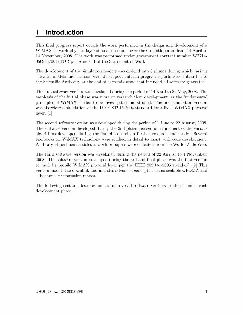
1 Introduction
This final progress report details the work performed in the design and development of aWiMAX network physical layer simulation model over the 6-month period from 14 April to14 November, 2008. The work was performed under government contract number W7714-050965/001/TOR per Annex H of the Statement of Work.
The development of the simulation models was divided into 3 phases during which varioussoftware models and versions were developed. Interim progress reports were submitted tothe Scientific Authority at the end of each milestone that included all software generated.
The first software version was developed during the period of 14 April to 30 May, 2008. Theemphasis of the initial phase was more on research than development, as the fundamentalprinciples of WiMAX needed to be investigated and studied. The first simulation versionwas therefore a simulation of the IEEE 802.16-2004 standard for a fixed WiMAX physicallayer. [1]
The second software version was developed during the period of 1 June to 22 August, 2008.The software version developed during the 2nd phase focused on refinement of the variousalgorithms developed during the 1st phase and on further research and study. Severaltextbooks on WiMAX technology were studied in detail to assist with code development.A library of pertinent articles and white papers were collected from the World Wide Web.
The third software version was developed during the period of 22 August to 4 November,2008. The software version developed during the 3rd and final phase was the first versionto model a mobile WiMAX physical layer per the IEEE 802.16e-2005 standard. [2] Thisversion models the downlink and includes advanced concepts such as scalable OFDMA andsubchannel permutation modes.
The following sections describe and summarize all software versions produced under eachdevelopment phase.
DRDC Ottawa CR 2008-296 1
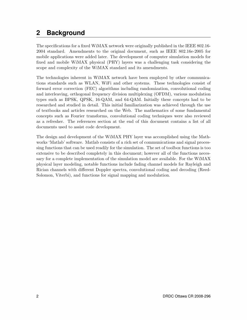
2 Background
The specifications for a fixed WiMAX network were originally published in the IEEE 802.16-2004 standard. Amendments to the original document, such as IEEE 802.16e-2005 formobile applications were added later. The development of computer simulation models forfixed and mobile WiMAX physical (PHY) layers was a challenging task considering thescope and complexity of the WiMAX standard and its amendments.
The technologies inherent in WiMAX network have been employed by other communica-tions standards such as WLAN, WiFi and other systems. These technologies consist offorward error correction (FEC) algorithms including randomization, convolutional codingand interleaving, orthogonal frequency division multiplexing (OFDM), various modulationtypes such as BPSK, QPSK, 16-QAM, and 64-QAM. Initially these concepts had to beresearched and studied in detail. This initial familiarization was achieved through the useof textbooks and articles researched on the Web. The mathematics of some fundamentalconcepts such as Fourier transforms, convolutional coding techniques were also reviewedas a refresher. The references section at the end of this document contains a list of alldocuments used to assist code development.
The design and development of the WiMAX PHY layer was accomplished using the Math-works ‘Matlab’ software. Matlab consists of a rich set of communications and signal proces-sing functions that can be used readily for the simulation. The set of toolbox functions is tooextensive to be described completely in this document; however all of the functions neces-sary for a complete implementation of the simulation model are available. For the WiMAXphysical layer modeling, notable functions include fading channel models for Rayleigh andRician channels with different Doppler spectra, convolutional coding and decoding (Reed-Solomon, Viterbi), and functions for signal mapping and modulation.
2 DRDC Ottawa CR 2008-296
3 Simulation Versions3.1 Version 1 - Basic Fixed WiMAX PHY Layer Simulation
3.1.1 Baseline
WiMAX is an emerging wireless broadband technology. Several companies have imple-mented computer simulation models of the WiMAX PHY layer; however the source codeof such simulations is not readily distributed. In order to get the started quickly, existingcode had to be found to serve as a take-off point or baseline. This first step was essentialin order not having to develop a WiMAX simulation model from scratch. As the WiMAXstandard is complex and extensive, developing a computer model from direct interpretationof the standard would have been too time consuming.
The first step taken was to investigate whether any existing WiMAX PHY layer simulationsexisted on the Mathworks Matlab users’ website. A simulation model was found, entitledEstudio y Simulacion de la capa fısica de la norma 802.16 (Sistema WiMAX) developed byCarlos Battles Ferrer in June 2007. Although the program was coded in Matlab, unfortu-nately all program comments and variable names were in Spanish and were impossible tocomprehend.
The text in the source files was translated from Spanish to English and variable names werereplaced with their English equivalents. This made the source code legible and allowed it tobe used as example code. More importantly, all of the program functions could be directlycorrelated to the specifications of the WiMAX standard.
The original and baseline version files are listed in Table 1.
The results of Ferrer WiMAX PHY layer simulation are output plots of the bit error rate(BER) versus the Eb/N0 (bit energy to noise power spectral density ratio). Several differentscenarios can be simulated in which parameters for modulation types, communicationschannel types, encoding, nominal bandwidth, and cyclic prefix length can be varied. TheFerrer simulation does not allow multiple users and is for a fixed WiMAX network. Theprogram allows the number of OFDM symbols transmitted to be specified by the user. TheBER converges to a more accurate value as the number of symbols transmitted increases.The program simulates only the downlink; the transmission interface from the base stationto the subscriber station.
The Ferrer simulation was adopted as the baseline for further code development as it servedas a good take-off point for further understanding and interpretation of the WiMAX stan-dard.
DRDC Ottawa CR 2008-296 3
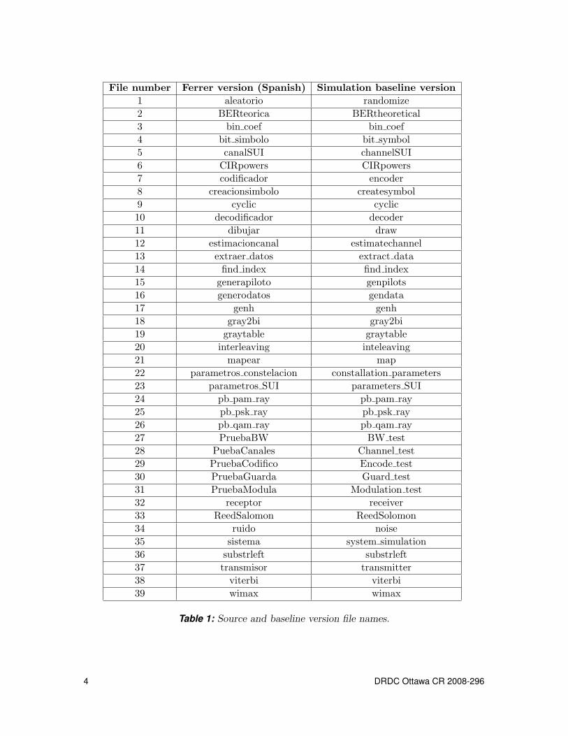
File number Ferrer version (Spanish) Simulation baseline version1 aleatorio randomize2 BERteorica BERtheoretical3 bin coef bin coef4 bit simbolo bit symbol5 canalSUI channelSUI6 CIRpowers CIRpowers7 codificador encoder8 creacionsimbolo createsymbol9 cyclic cyclic10 decodificador decoder11 dibujar draw12 estimacioncanal estimatechannel13 extraer datos extract data14 find index find index15 generapiloto genpilots16 generodatos gendata17 genh genh18 gray2bi gray2bi19 graytable graytable20 interleaving inteleaving21 mapear map22 parametros constelacion constallation parameters23 parametros SUI parameters SUI24 pb pam ray pb pam ray25 pb psk ray pb psk ray26 pb qam ray pb qam ray27 PruebaBW BW test28 PuebaCanales Channel test29 PruebaCodifico Encode test30 PruebaGuarda Guard test31 PruebaModula Modulation test32 receptor receiver33 ReedSalomon ReedSolomon34 ruido noise35 sistema system simulation36 substrleft substrleft37 transmisor transmitter38 viterbi viterbi39 wimax wimax
Table 1: Source and baseline version file names.
4 DRDC Ottawa CR 2008-296
3.1.2 Technical description
3.1.2.1 Fading channels
The simulation of the WiMAX PHY layer begins with modeling of the communicationschannel through which signals propagate from the transmitter to the receiver. Properchannel modeling is a critical part of the simulation as the signals experience attenuation,delay spread, Doppler frequency shifts (in case of a moving receiver), and multipath re-flections that degrade the signal’s quality as it passes through the channel. The signalpropagation can be via line-of-sight and non-line-of-sight paths.
The model uses the SUI (Stanford University Interim) channel models to describe the fad-ing channels for various urban and rural environments and terrain types. Six SUI channelmodels have been adopted that adequately describe various parameters that define a com-munications channel. These parameters include path loss, multipath delay spread, fadingcharacteristics, Doppler spread and co-channel interference. [3]
Upon review and examination of the Ferrer model, it was concluded that the channelmodeling was not correctly implemented. The Doppler spectrum for the SUI channel modelswas being set up as a classical Jakes model, which the SUI channels are not. Code changeswere made to channelSUI.m as follows:
% Obtain the SUI channel parameters.(powers, K, delay, Dop, ant corr, Fnorm) = parameters SUI(N SUI);% Convert path delays to microseconds.tau = delays*1e-6;% Calculate the frequency-selective fading channel object% with a rounded Doppler spectrum.h=ricianchannel(1/Fs, max(Dop), K, tau, powers);h.DopplerSpectrum=doppler.rounded;channel = h.PathGains;
The ‘channel’ quantity obtained above is a complex vector describing the discrete pathgains. The variable ‘1/Fs’ is the sampling period and is a function of the bandwidth and asampling correction factor ‘n’ specified by the WiMAX standard.
3.1.2.2 OFDM symbol creation
The WiMAX PHY layer uses OFDM to combat multipath effects such as channel fades,intersymbol interference and delay spread through the use of orthogonal subcarrier fre-quencies. OFDM is a key component of WiMAX and is a combination of modulationand multiplexing. How an OFDM symbol is created is essential to the understanding ofWiMAX.
The fixed WiMAX standard specifies that the available bandwidth is divided into 256subcarrier frequencies. A total of 64 subcarrier frequencies are reserved for guard bands,
DRDC Ottawa CR 2008-296 5
pilot frequencies and a DC component, leaving the remaining 192 subcarriers for datatransmission. The transmitted data is multiplexed and modulated onto the 192 orthogonalsubcarriers. The orthogonal nature of the subcarriers assures that these frequencies do notproduce intermodulation products.
The first step of the OFDM symbol creation begins with determining how many bits needto be generated. This function is implemented in the gendata.m file. For each modulationtype and coding rate combination, the WiMAX standard specifies the uncoded block size(UBS) required to form the OFDM symbol, however the UBS is easily calculated as follows:
For example, if the modulation type is 16-QAM, 4-bits are used to code each bit of thedata. If the coding rate is 1
2 , then the UBS is: 192*4/2 = 384-bits or 48-bytes. Actuallythe UBS is 1-byte less as a zero-pad byte is added in a following Reed-Solomon encoderstep. A Matlab random number generator (randint) is used to generate the initial randomdata bytes of simulated data.
The random data bytes generated by gendata.m are output as a [376 x 1] vector that enterthe randomization stage of the forward error correction (FEC) chain. Data randomizationintroduces protection through information theoretical uncertainty by avoiding possible long,repetitive sequences of 1s and 0s, which otherwise may cause discrete tones in the modulatedsignal. The output of the randomizer function is also a [376 x 1] vector.
The randomizer stage is followed by the Reed-Solomon encoder which is implemented usingthe ReedSolomon.m function. For 16-QAM modulation and 1
2 coding rate the WiMAXstandard specifies [64, 48] Reed-Solomon encoding. Therefore 47-bytes (376-bits) entersthe Reed-Solomon encoder, a zero-pad byte is added and the output is 64-bytes (512-bits).The output of the Reed-Solomon encoder is therefore a [512 x 1] vector.
Next, the Reed-Solomon encoded data enters a convolutional encoder of native rate 12 . The
output vector is [1024 x 1]. This vector gets punctured for a rate of 4/3 as specified by theWiMAX standard. The overall convolutional coding rate is therefore 1
2 * 4/3 = 2/3. Theoutput after puncturing is 128-bytes (1024-bits) / 4/3 = 96-bytes (768-bits). The overallcoding rate for 16-QAM modulation example is therefore 48/96 = 2/3 as specified by theWiMAX standard. Figure 1 shows the forward error correction stages in the OFDM symbolcreation process.
Next, the convolutionally encoded and punctured data enters a two-step interleaver toensure that adjacent coded bits are mapped onto nonadjacent subcarriers. This procedureis performed by the interleaving.m function. The output of the interleaver is a [768 x 1]vector.
So far the data has been massaged through forward error correction (FEC) algorithms toguard it against inter-symbol interference. In the next step the data is modulated onto thesubcarriers. This is accomplished by Gray encoding the data onto the constellation map ofthe modulation type used. In the simulation this is accomplished by the map.m function.The WiMAX standard specifies the constellation maps for BPSK, QPSK, 16-QAM and 64-
6 DRDC Ottawa CR 2008-296
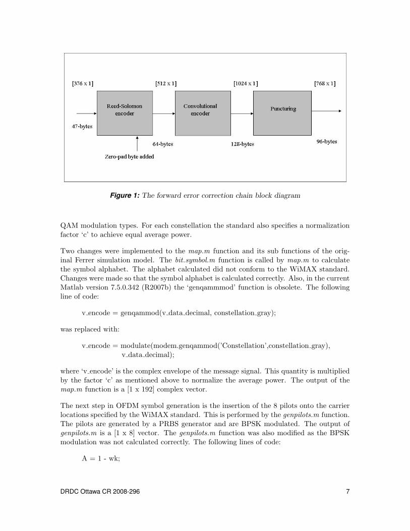
Figure 1: The forward error correction chain block diagram
QAM modulation types. For each constellation the standard also specifies a normalizationfactor ‘c’ to achieve equal average power.
Two changes were implemented to the map.m function and its sub functions of the orig-inal Ferrer simulation model. The bit symbol.m function is called by map.m to calculatethe symbol alphabet. The alphabet calculated did not conform to the WiMAX standard.Changes were made so that the symbol alphabet is calculated correctly. Also, in the currentMatlab version 7.5.0.342 (R2007b) the ‘genqammmod’ function is obsolete. The followingline of code:
v encode = genqammod(v data decimal, constellation gray);
was replaced with:
v encode = modulate(modem.genqammod(’Constellation’,constellation gray),v data decimal);
where ‘v encode’ is the complex envelope of the message signal. This quantity is multipliedby the factor ‘c’ as mentioned above to normalize the average power. The output of themap.m function is a [1 x 192] complex vector.
The next step in OFDM symbol generation is the insertion of the 8 pilots onto the carrierlocations specified by the WiMAX standard. This is performed by the genpilots.m function.The pilots are generated by a PRBS generator and are BPSK modulated. The output ofgenpilots.m is a [1 x 8] vector. The genpilots.m function was also modified as the BPSKmodulation was not calculated correctly. The following lines of code:
A = 1 - wk;
DRDC Ottawa CR 2008-296 7
B = 1 - ( wk);value carrier = [A B A B B B A A];mapped pilots = 2*map(value carrier, 1, Tx);
was changed to:
A = 1 - 2*wk;B = 1 - 2*( wk);value carrier = [A B A B B B A A];mapped pilots = complex(value carrier);
The mapped data and pilot vectors are passed to the transmitter.m function which com-pletes the OFDM symbol by inserting the data, pilots, guard bands and DC componentsinto their respective locations as specified by the standard. This is accomplished using thecreatesymbol.m function.
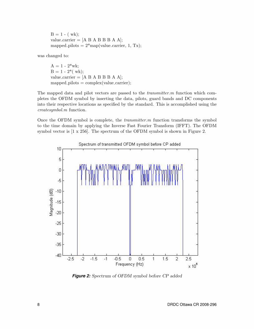
Once the OFDM symbol is complete, the transmitter.m function transforms the symbolto the time domain by applying the Inverse Fast Fourier Transform (IFFT). The OFDMsymbol vector is [1 x 256]. The spectrum of the OFDM symbol is shown in Figure 2.
Figure 2: Spectrum of OFDM symbol before CP added
8 DRDC Ottawa CR 2008-296
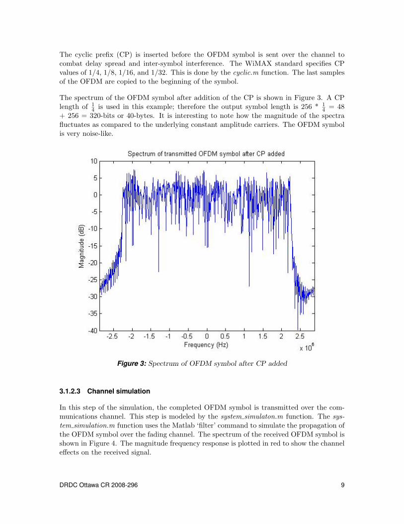
The cyclic prefix (CP) is inserted before the OFDM symbol is sent over the channel tocombat delay spread and inter-symbol interference. The WiMAX standard specifies CPvalues of 1/4, 1/8, 1/16, and 1/32. This is done by the cyclic.m function. The last samplesof the OFDM are copied to the beginning of the symbol.
The spectrum of the OFDM symbol after addition of the CP is shown in Figure 3. A CPlength of 1
4 is used in this example; therefore the output symbol length is 256 * 14 = 48
+ 256 = 320-bits or 40-bytes. It is interesting to note how the magnitude of the spectrafluctuates as compared to the underlying constant amplitude carriers. The OFDM symbolis very noise-like.
Figure 3: Spectrum of OFDM symbol after CP added
3.1.2.3 Channel simulation
In this step of the simulation, the completed OFDM symbol is transmitted over the com-munications channel. This step is modeled by the system simulaton.m function. The sys-tem simulation.m function uses the Matlab ‘filter’ command to simulate the propagation ofthe OFDM symbol over the fading channel. The spectrum of the received OFDM symbol isshown in Figure 4. The magnitude frequency response is plotted in red to show the channeleffects on the received signal.
DRDC Ottawa CR 2008-296 9
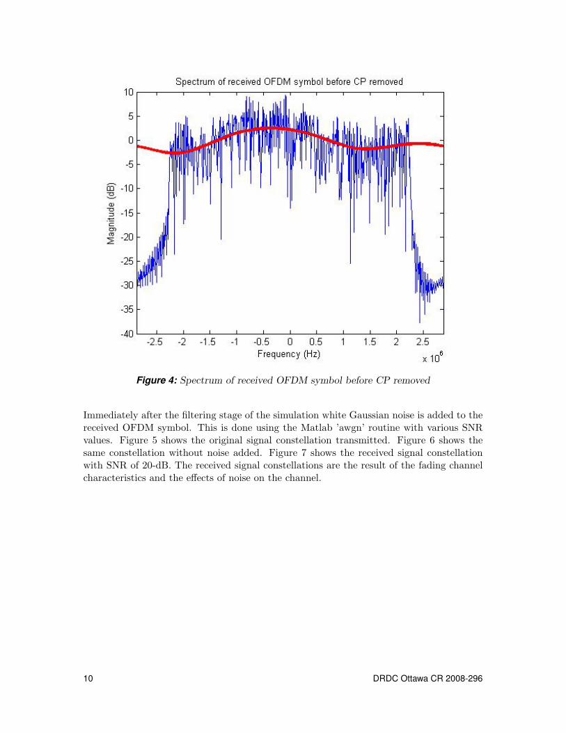
Figure 4: Spectrum of received OFDM symbol before CP removed
Immediately after the filtering stage of the simulation white Gaussian noise is added to thereceived OFDM symbol. This is done using the Matlab ’awgn’ routine with various SNRvalues. Figure 5 shows the original signal constellation transmitted. Figure 6 shows thesame constellation without noise added. Figure 7 shows the received signal constellationwith SNR of 20-dB. The received signal constellations are the result of the fading channelcharacteristics and the effects of noise on the channel.
10 DRDC Ottawa CR 2008-296
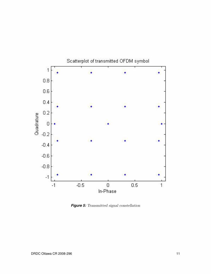
Figure 5: Transmitted signal constellation
DRDC Ottawa CR 2008-296 11
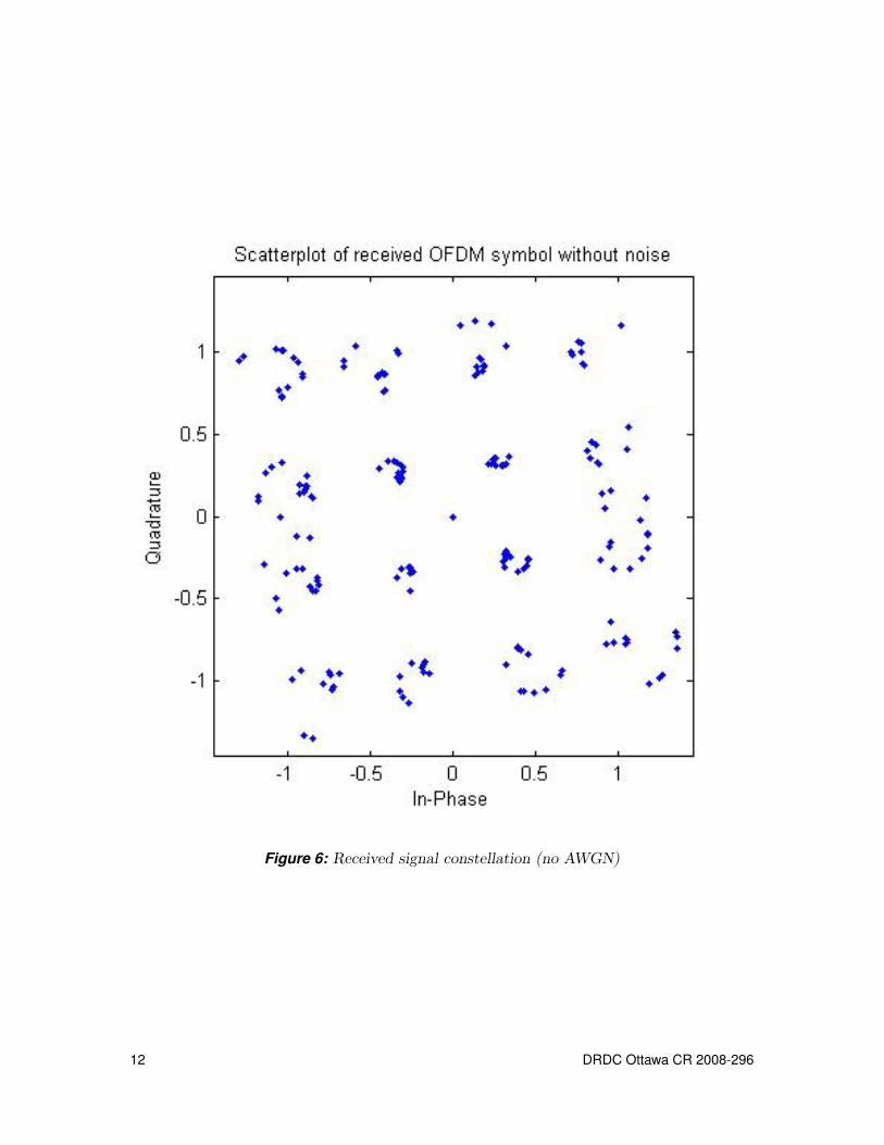
Figure 6: Received signal constellation (no AWGN)
12 DRDC Ottawa CR 2008-296
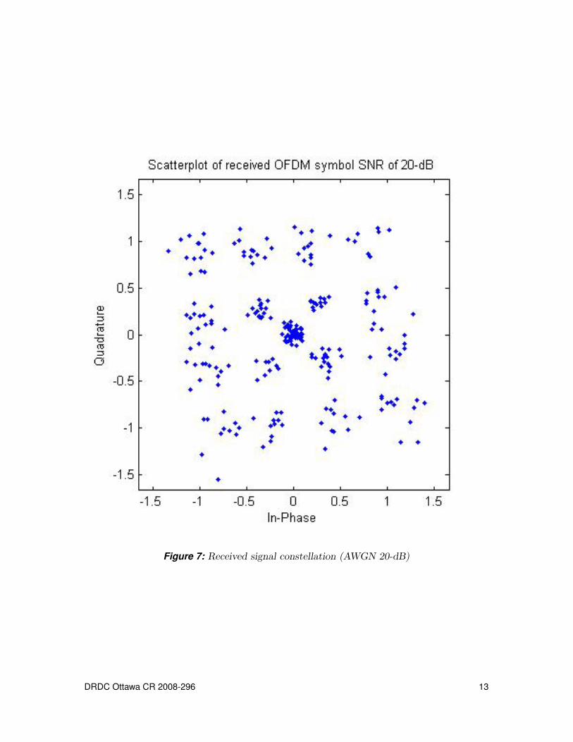
Figure 7: Received signal constellation (AWGN 20-dB)
DRDC Ottawa CR 2008-296 13
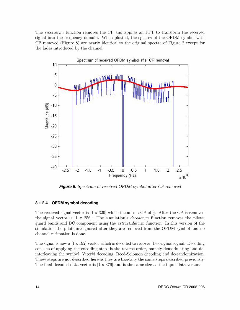
The receiver.m function removes the CP and applies an FFT to transform the receivedsignal into the frequency domain. When plotted, the spectra of the OFDM symbol withCP removed (Figure 8) are nearly identical to the original spectra of Figure 2 except forthe fades introduced by the channel.
Figure 8: Spectrum of received OFDM symbol after CP removed
3.1.2.4 OFDM symbol decoding
The received signal vector is [1 x 320] which includes a CP of 14 . After the CP is removed
the signal vector is [1 x 256]. The simulation’s decoder.m function removes the pilots,guard bands and DC component using the extract data.m function. In this version of thesimulation the pilots are ignored after they are removed from the OFDM symbol and nochannel estimation is done.
The signal is now a [1 x 192] vector which is decoded to recover the original signal. Decodingconsists of applying the encoding steps is the reverse order, namely demodulating and de-interleaving the symbol, Viterbi decoding, Reed-Solomon decoding and de-randomization.These steps are not described here as they are basically the same steps described previously.The final decoded data vector is [1 x 376] and is the same size as the input data vector.
14 DRDC Ottawa CR 2008-296
3.1.2.5 BER calculation
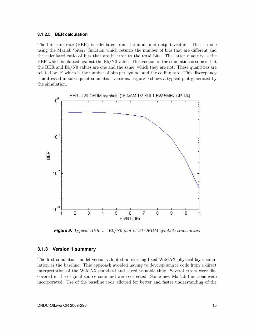
The bit error rate (BER) is calculated from the input and output vectors. This is doneusing the Matlab ‘biterr’ function which returns the number of bits that are different andthe calculated ratio of bits that are in error to the total bits. The latter quantity is theBER which is plotted against the Eb/N0 value. This version of the simulation assumes thatthe BER and Eb/N0 values are one and the same, which they are not. These quantities arerelated by ‘k’ which is the number of bits per symbol and the coding rate. This discrepancyis addressed in subsequent simulation versions. Figure 9 shows a typical plot generated bythe simulation.
Figure 9: Typical BER vs. Eb/N0 plot of 20 OFDM symbols transmitted
3.1.3 Version 1 summary
The first simulation model version adopted an existing fixed WiMAX physical layer simu-lation as the baseline. This approach avoided having to develop source code from a directinterpretation of the WiMAX standard and saved valuable time. Several errors were dis-covered in the original source code and were corrected. Some new Matlab functions wereincorporated. Use of the baseline code allowed for better and faster understanding of the
DRDC Ottawa CR 2008-296 15
technologies used by WiMAX.
The work performed enabled a thorough review of the fundamental concepts used in a fixedWiMAX network. A good understanding of these concepts and methods was essential toprogressing ahead with the design and implementation of more thorough fixed and mobileWiMAX physical layer simulations.
3.2 Version 3 - Improved Fixed WiMAX PHY Layer Simulation
3.2.1 Background
During the first phase of code development a baseline version (V1) of the simulation modelwas produced. This simulation model was limited to the modeling of a fixed WiMAX PHYlayer per the original IEEE802.16-2004 standard. During the 2nd phase of developmentan extensive study was undertaken to extend the baseline version to include componentsdefined for mobile WiMAX applications per the IEEE802.16e-2005 standard.
A mobile WiMAX system is based on scalable orthogonal frequency division multiple access(SOFDMA) and includes other advanced concepts such as subchannelization, channel esti-mation techniques, adaptive modulation and coding (AMC) and use of multiple transmitand receive antennas (MIMO). In order to understand these concepts, several textbookswere read and relevant articles were researched on the Web. Matlab programs were deve-loped in order to implement these concepts into software.
During the 2nd phase the original version of the baseline software (V1) was simplified. Thetotal number of source files was reduced from 39 to 23. Several redundant or unused sourcefiles were removed.
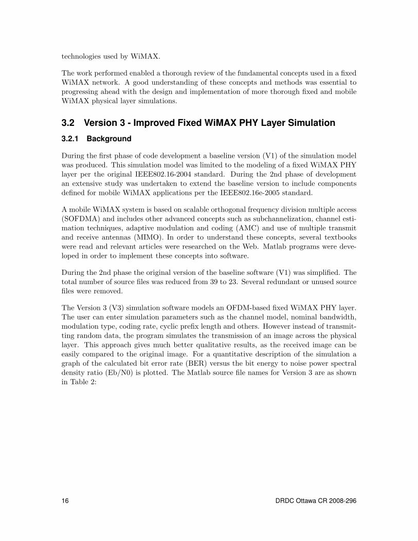
The Version 3 (V3) simulation software models an OFDM-based fixed WiMAX PHY layer.The user can enter simulation parameters such as the channel model, nominal bandwidth,modulation type, coding rate, cyclic prefix length and others. However instead of transmit-ting random data, the program simulates the transmission of an image across the physicallayer. This approach gives much better qualitative results, as the received image can beeasily compared to the original image. For a quantitative description of the simulation agraph of the calculated bit error rate (BER) versus the bit energy to noise power spectraldensity ratio (Eb/N0) is plotted. The Matlab source file names for Version 3 are as shownin Table 2:
16 DRDC Ottawa CR 2008-296
File number File name1 bit symbol2 channelSUI3 constellation parameters4 createsymbol5 cyclic6 decoder7 encoder8 estimatechannel9 extract data10 find index11 gendata12 genpilots13 interleaving14 map15 parameters SUI16 randomize17 receiver18 ReedSolomon19 run rgswimax sim20 system simulation21 transmitter22 validate input23 viterbi
Table 2: Version 3 source file names.
DRDC Ottawa CR 2008-296 17
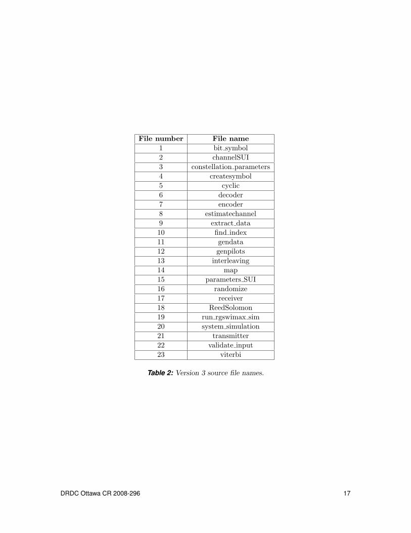
3.2.2 Program execution
The V3 simulation is executed by calling the run rgswimax sim.m file. The following dialogmessage appears:
========================================================== Simulation program for downlink WiMAX PHY layer=== Version 3.0====== Author : RGS=== DRDC, Ottawa, Ontario=== Date : August 2008=============================================================
Enter SUI channel: 1 to 6 (AWGN=0) [1]:Enter modulation type: 1-BPSK, 2-QPSK, 3-16QAM, 4-64QAM [3]:Enter 16QAM code rate: 2/3, 5/6 or 0 (no encoding) [2/3]:Enter CP value: 1/4, 1/8, 1/16, 1/32 [1/4]:Enter nominal BW (MHz): 20,10,5,3.5,1.25 [5]:
SNR range 10.00 dB to 16.00 dB will be simulatedEnter SNR steps (dB): 0.10 to 1.00 [0.50]:Save input data to file? 0 or 1 [0]:Simulation input data will not be saved..
Running simulation..
Default values are available for each input parameter and parameter checking is performed.The user can only specify values selected from the list shown for each parameter. Forexample, values of 1, 2, 3, or 4 can be entered for modulation type. Other values are notaccepted and the user is prompted to re-specify a correct value.
The simulation transmits a JPG image with array dimensions of 360,000-bytes (300x400x3array). When the default burst profile is used by the simulation, 47-bytes are used toform the OFDM symbol. The simulation time per OFDM symbol was measured to be0.75-seconds average. This implies a total of 1.6-hours to transmit the entire image. Thetotal simulation time for generating 13-images (e.g. for SNR values ranging from 10.0-dBto 16.0-dB, in 0.5-dB increments) is approximately 20.8-hours. The following figure showsthe display while the simulation is executing.
18 DRDC Ottawa CR 2008-296
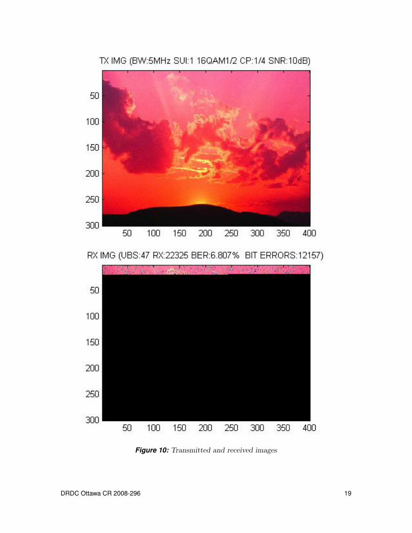
Figure 10: Transmitted and received images
DRDC Ottawa CR 2008-296 19
The upper portion of Figure 10 shows the transmitted image. The burst profile is 16-QAMmodulation with a coding rate 1
2 . The length of the cyclic prefix is 14 and the SNR is 10-dB.
The lower portion of Figure 10 displays the received image. At the time when the imagewas captured, a total of 22325-bytes were received out of which 12157-bits were in error.The instantaneous total BER is therefore 6.81%. The figure also shows the uncoded blocksize (UBS), which in this case is 47-bytes.
3.2.3 Simulation model changes
The estimatechannel.m source file was changed to incorporate a pilot-based channel esti-mation algorithm. The first version (V1) of the simulation used the known fading channelgains to extract the data from the received signal. The algorithm was based on the arti-cle “Error Probability Minimizing Pilots for OFDM with M-PSK Modulation over RayleighFading Channels” [4].
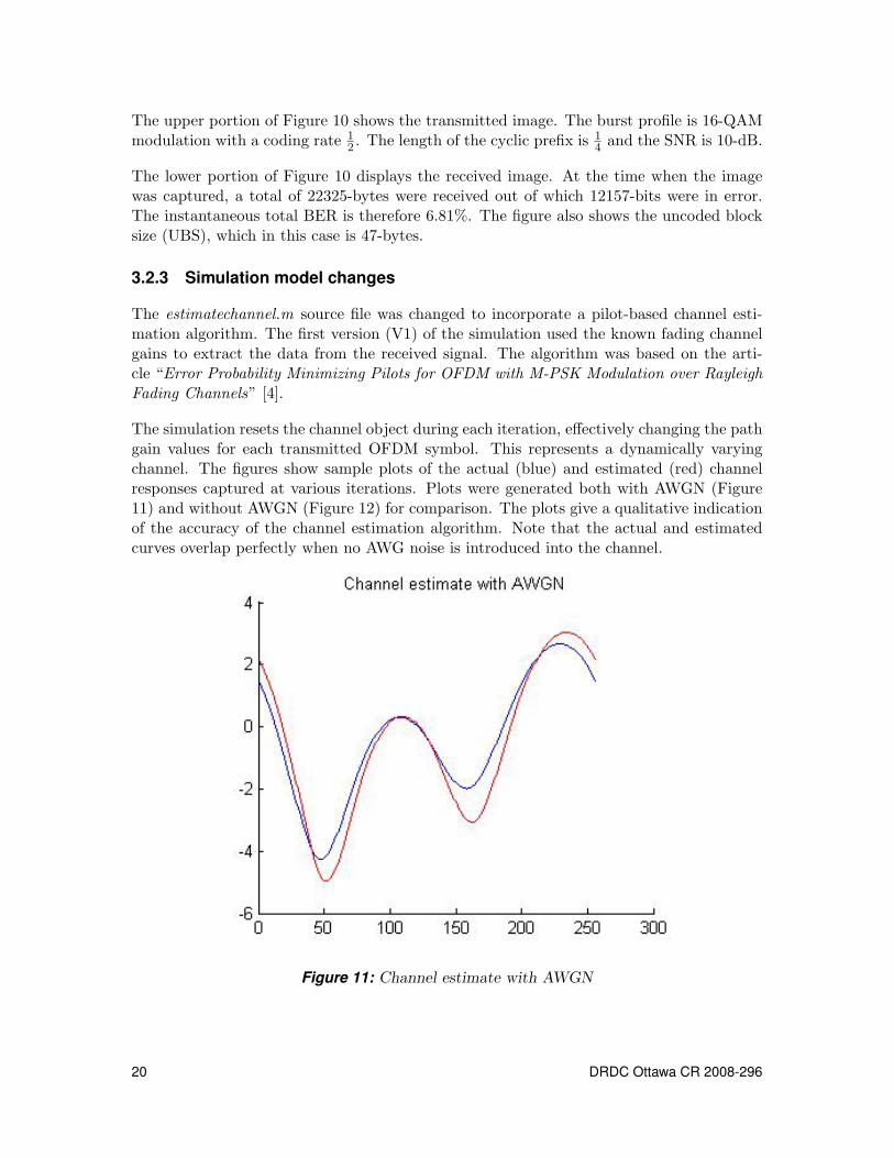
The simulation resets the channel object during each iteration, effectively changing the pathgain values for each transmitted OFDM symbol. This represents a dynamically varyingchannel. The figures show sample plots of the actual (blue) and estimated (red) channelresponses captured at various iterations. Plots were generated both with AWGN (Figure11) and without AWGN (Figure 12) for comparison. The plots give a qualitative indicationof the accuracy of the channel estimation algorithm. Note that the actual and estimatedcurves overlap perfectly when no AWG noise is introduced into the channel.
Figure 11: Channel estimate with AWGN
20 DRDC Ottawa CR 2008-296
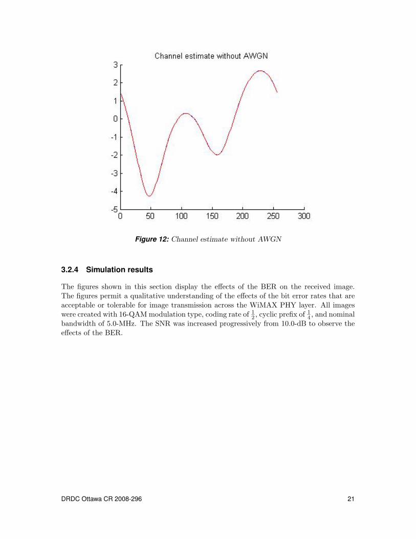
Figure 12: Channel estimate without AWGN
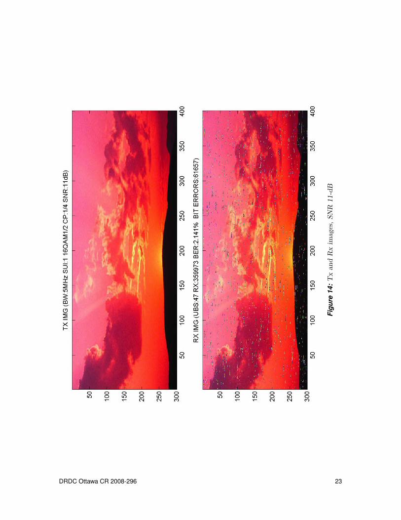
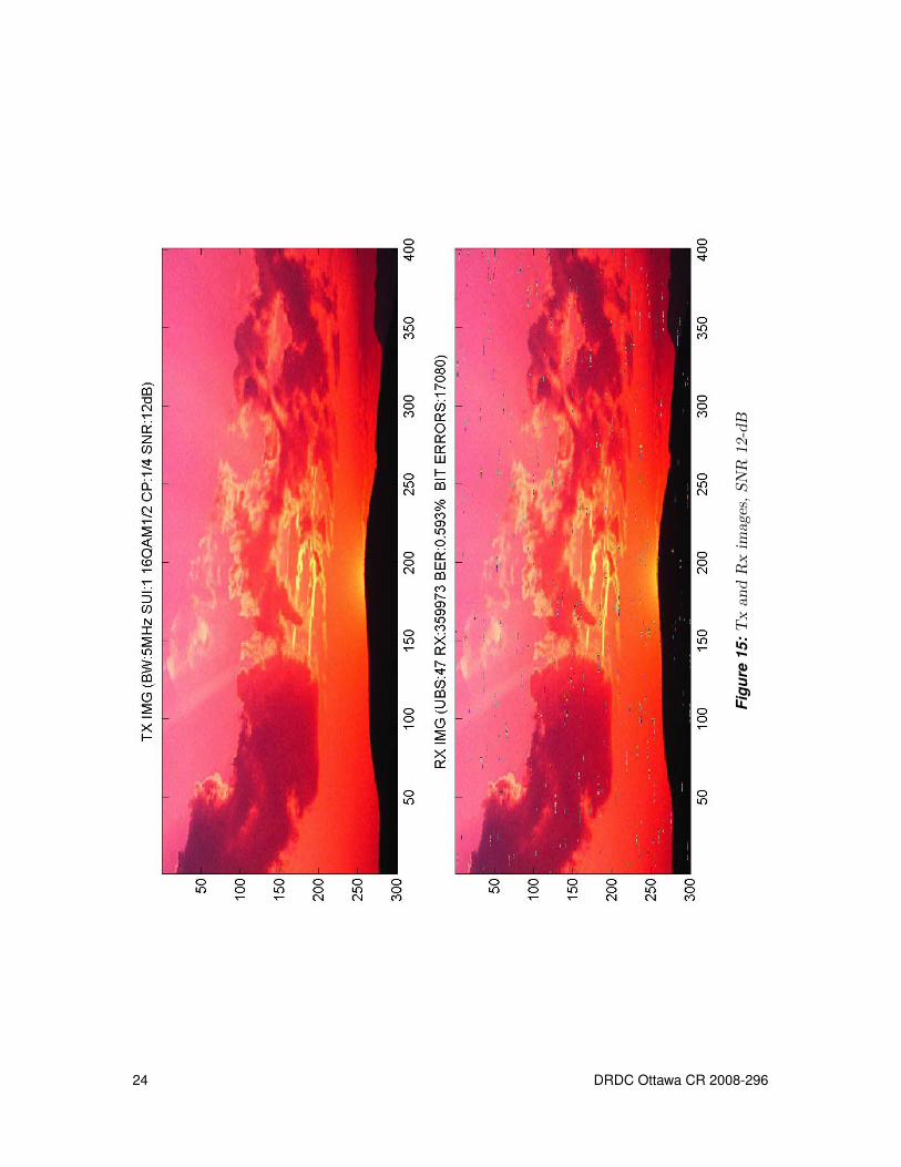
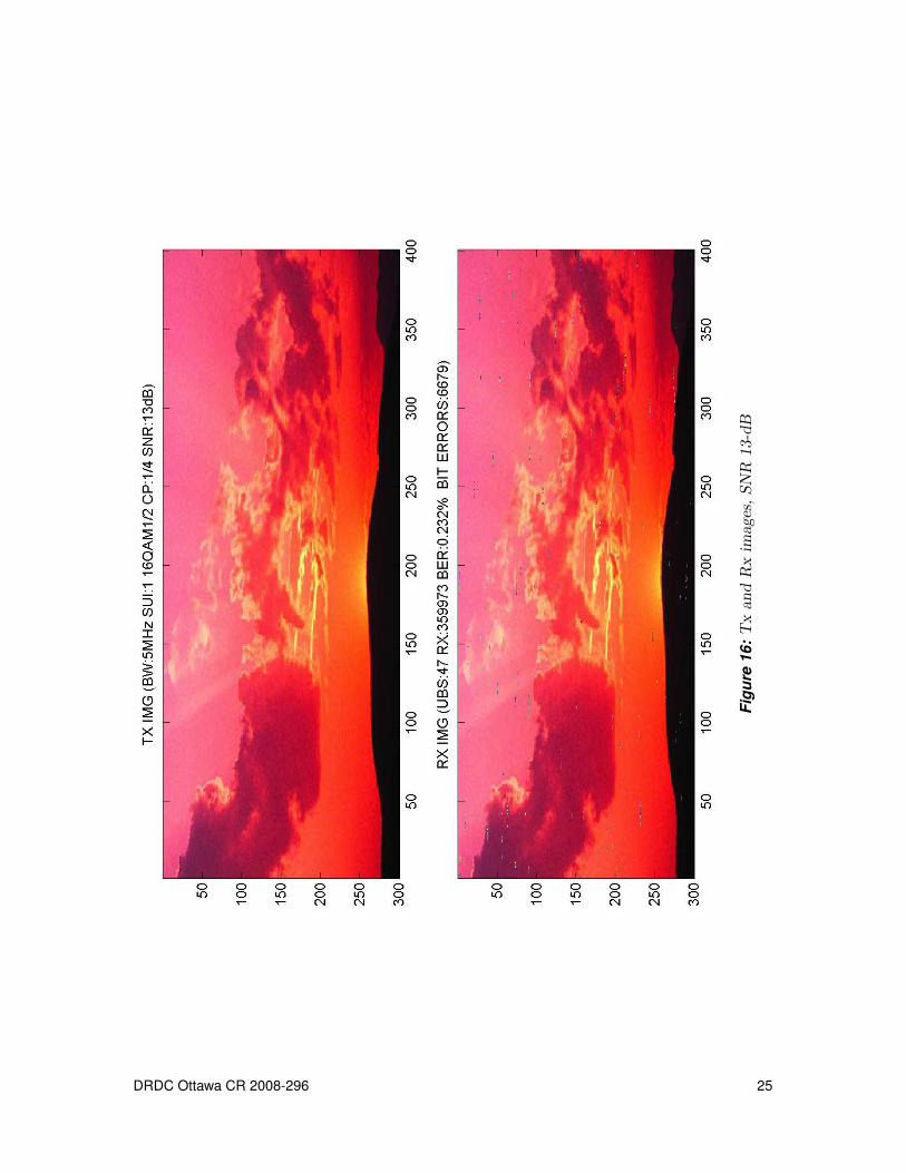
3.2.4 Simulation results
The figures shown in this section display the effects of the BER on the received image.The figures permit a qualitative understanding of the effects of the bit error rates that areacceptable or tolerable for image transmission across the WiMAX PHY layer. All imageswere created with 16-QAM modulation type, coding rate of 1
2 , cyclic prefix of 14 , and nominal
bandwidth of 5.0-MHz. The SNR was increased progressively from 10.0-dB to observe theeffects of the BER.
DRDC Ottawa CR 2008-296 21
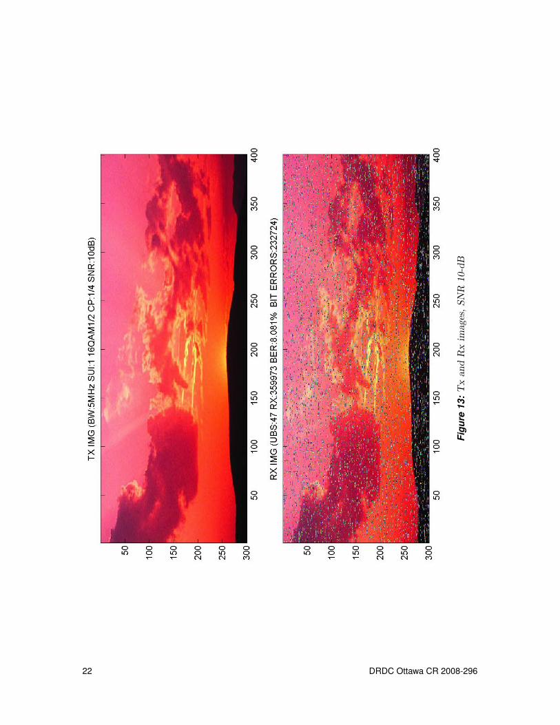
Figu
re13
:T
xan
dR
xim
ages
,SN
R10
-dB
22 DRDC Ottawa CR 2008-296
Figu
re14
:T
xan
dR
xim
ages
,SN
R11
-dB
DRDC Ottawa CR 2008-296 23
Figu
re15
:T
xan
dR
xim
ages
,SN
R12
-dB
24 DRDC Ottawa CR 2008-296
Figu
re16
:T
xan
dR
xim
ages
,SN
R13
-dB
DRDC Ottawa CR 2008-296 25
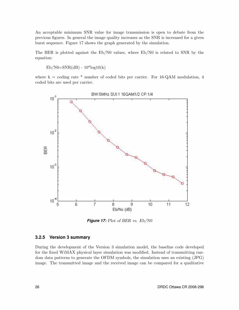
An acceptable minimum SNR value for image transmission is open to debate from theprevious figures. In general the image quality increases as the SNR is increased for a givenburst sequence. Figure 17 shows the graph generated by the simulation.
The BER is plotted against the Eb/N0 values, where Eb/N0 is related to SNR by theequation:
Eb/N0=SNR(dB) - 10*log10(k)
where k = coding rate * number of coded bits per carrier. For 16-QAM modulation, 4coded bits are used per carrier.
Figure 17: Plot of BER vs. Eb/N0
3.2.5 Version 3 summary
During the development of the Version 3 simulation model, the baseline code developedfor the fixed WiMAX physical layer simulation was modified. Instead of transmitting ran-dom data patterns to generate the OFDM symbols, the simulation uses an existing (JPG)image. The transmitted image and the received image can be compared for a qualitative
26 DRDC Ottawa CR 2008-296
understanding of the PHY layer effects. The program plots the accumulated results for aquantitative analysis.
A channel estimation algorithm was incorporated into the code that is quite accurate andis based on published work. The V3 simulation program uses the estimated fading channelgains to recover the received OFDM symbol.
During the 2nd phase of development, work was started to modify the simulation to includescalable OFDMA which is the basis of a mobile WiMAX PHY layer. Routines were codedto enable subchannelization; a fundamental feature of mobile WiMAX.
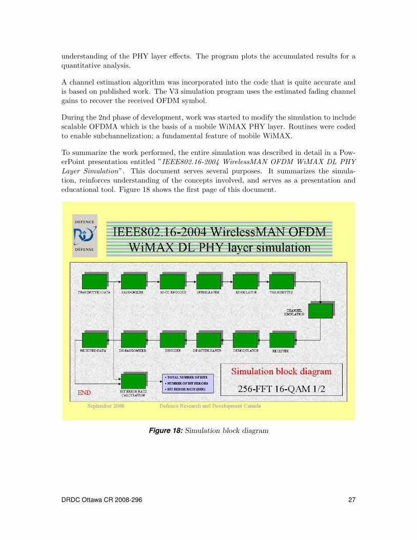
To summarize the work performed, the entire simulation was described in detail in a Pow-erPoint presentation entitled ”IEEE802.16-2004 WirelessMAN OFDM WiMAX DL PHYLayer Simulation”. This document serves several purposes. It summarizes the simula-tion, reinforces understanding of the concepts involved, and serves as a presentation andeducational tool. Figure 18 shows the first page of this document.
Figure 18: Simulation block diagram
DRDC Ottawa CR 2008-296 27

3.3 Version 5 - Basic Mobile WiMAX PHY Layer Simulation
3.3.1 Background
During the 1st and 2nd phase of simulation development, important fundamental conceptswere learned. These concepts were essential to develop an accurate, although limited,simulation model of a mobile WiMAX PHY layer as specified by the IEEE 802.16e-2005standard.
Version 5 of the software models the downlink (DL) from the base station (BS) to a mobilestation (MS). The model employs scalable OFDMA, subchannelization, and preamble-basedchannel estimation techniques. The software partially models the MAC layer as it generatespseudo-MAC layer management messages to the PHY layer. The simulation consists of theMatlab files shown in Table 3.
3.3.2 Technical description
A complete explanation of the mobile WiMAX PHY layer is beyond the scope of thisdocument. Only brief explanations of key concepts are presented. The program flow isgiven in the following steps.
1. The model inputs several parameters such as the nominal bandwidth, the cyclic prefix,the SUI channel index, the signal-to-noise ratio, and other parameters required by thesimulation. All input parameters use the ’ip ’ prefix (i.e. ip BW to specify the nominalinput bandwidth).
2. The model selects the number of FFT points based on the nominal bandwidth specified.In mobile WiMAX the bandwidth can be 1.25, 5.0, 10.0 or 20.0 MHz corresponding to FFTpoints of 128, 512, 1024 and 2048 respectively. This implementation keeps the subcarrierspacing constant at 10.94-KHz. This technique is known as scalable OFDMA or SOFDMA.The nominal bandwidth is multiplied by a normalization factor specified by the standard.
3. The model generates Rician or Rayleigh fading channels to model the communicationschannel. As in previous simulation versions, 6 SUI channels can be specified to modelvarious terrain types, scattering environments and Doppler frequencies.
4. The model defines 4 user IDs and 6 different downlink interval usage codes (DIUCs). ADIUC defines the modulation type, coding type and coding rate used for each DL burst ordata region within a downlink subframe. Connection IDs (CIDs) are used to specify to themobile station the DIUCs assigned to each user. The number of users, DIUCs and CIDscan be varied in the program.
The simulation uses the following input definitions:
ip user ID = [{’a10c’} {’b28f’} {’c30c’} {’d99f’}];ip DIUC = [0 1 2 3 4 5];
28 DRDC Ottawa CR 2008-296
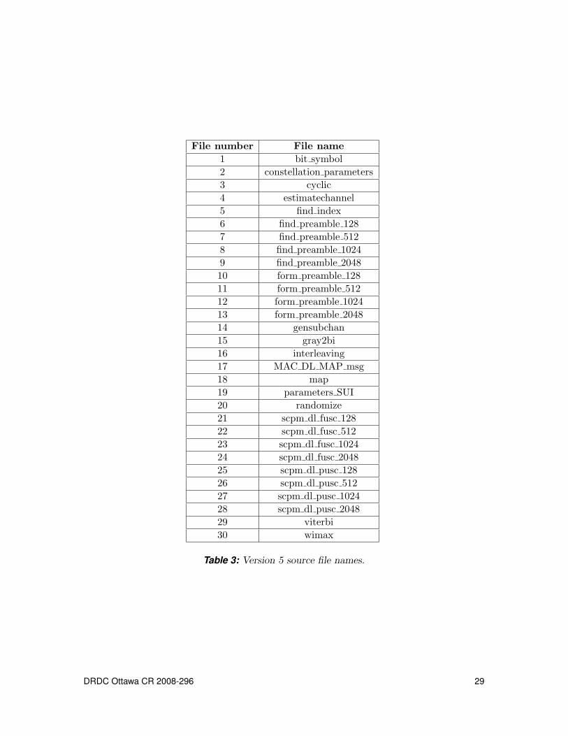
File number File name1 bit symbol2 constellation parameters3 cyclic4 estimatechannel5 find index6 find preamble 1287 find preamble 5128 find preamble 10249 find preamble 204810 form preamble 12811 form preamble 51212 form preamble 102413 form preamble 204814 gensubchan15 gray2bi16 interleaving17 MAC DL MAP msg18 map19 parameters SUI20 randomize21 scpm dl fusc 12822 scpm dl fusc 51223 scpm dl fusc 102424 scpm dl fusc 204825 scpm dl pusc 12826 scpm dl pusc 51227 scpm dl pusc 102428 scpm dl pusc 204829 viterbi30 wimax
Table 3: Version 5 source file names.
DRDC Ottawa CR 2008-296 29
ip CID = [{[1 2 3 4]} {[1 2]} {[3 4]} {[1]} {[2]} {[3]}];
Here CID 1 uses DIUC 0 and is assigned to users 1, 2, 3 and 4; therefore all users willreceive the data sent on this connection. This is a form of multicast operation. CID 6 usesDIUC 5 but is intended only for user 3 with ID 0xc30c.
5. The above parameters are normally issued to the PHY layer by a MAC DL-MAPmanagement message. The MAC layer message also informs the PHY layer on how the DLsubframe is to be structured. It specifies the start and end symbols and subchannels withinthe subframe for each DIUC. The DL MAP message is transmitted to the MS in the DLsubframe so the MS knows how to decode (unmap) the data.
The model calls the MAC DL MAP msg.m function to generate a pseudo-MAC layer man-agement message. The returned message is randomized, convolutionally encoded, inter-leaved and modulated. QPSK CC 1
2 is used as specified by the standard. (The DL MAP,UL MAP and frame control header are always transmitted using QPSK modulation asspecified by the standard).
6. The model sets up a mapping matrix whose size is determined by the total number ofOFDMA symbols and subchannels used. The number of symbols is limited by the frameduration which is typically 5-msec. The number of subchannels used depends on the FFTsize (itself being a function of the bandwidth used). The mapping matrix is filled with theDIUCs defined by the MAC DL MAP message.
7. The model generates 2-Kbytes of random data to be transmitted on each DL burst andcalculates the maximum number of concatenated slots available for each data region. A slotis the basic data unit in OFDMA. For DL FUSC (full usage of subcarriers) permutationmode, a slot is 1-OFDMA symbol by 1-subchannel. For DL PUSC (partial usage of sub-carriers) permutation mode, a slot is 2-OFDMA symbols by 1-subchannel. Based on theDIUC assigned to a data region, the model calculates the uncoded block size (UBS) thatcan be mapped into each data region. The UBS is used to ’cut’ portions of the randomdata that will completely fill each data region.
8. The model randomizes, convolutionally encodes, interleaves and modulates each databurst per the DIUC assigned by the mapping matrix.
9. The DL subframe matrix is generated. The size of this matrix is the number of FFTpoints used by the number of OFDMA symbols. This matrix holds all data that is readyto be transmitted across the interface.
10. Next, the frame preamble is generated based on the number of FFT points usedand on the Cell ID assigned to each segment. Three segments are used within each cellcorresponding to three transmit antennas. The preamble is created from pseudo-noise (PN)sequences defined by the standard. The preamble is BPSK modulated for reliable recoveryeven in worst case SNR conditions and carriers are boosted by 9.0-dB.
30 DRDC Ottawa CR 2008-296
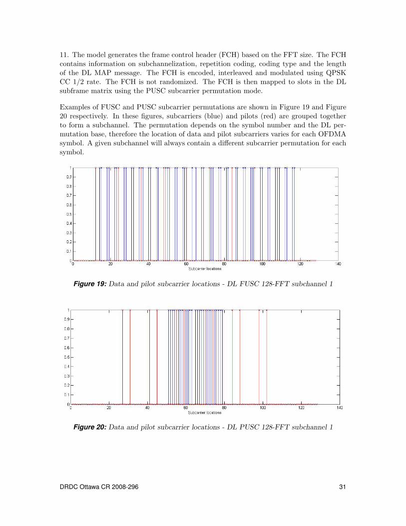
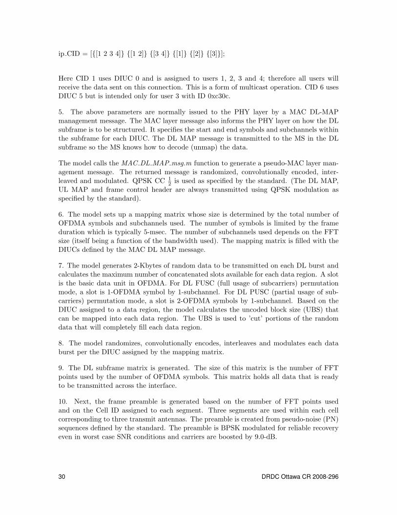
11. The model generates the frame control header (FCH) based on the FFT size. The FCHcontains information on subchannelization, repetition coding, coding type and the lengthof the DL MAP message. The FCH is encoded, interleaved and modulated using QPSKCC 1/2 rate. The FCH is not randomized. The FCH is then mapped to slots in the DLsubframe matrix using the PUSC subcarrier permutation mode.
Examples of FUSC and PUSC subcarrier permutations are shown in Figure 19 and Figure20 respectively. In these figures, subcarriers (blue) and pilots (red) are grouped togetherto form a subchannel. The permutation depends on the symbol number and the DL per-mutation base, therefore the location of data and pilot subcarriers varies for each OFDMAsymbol. A given subchannel will always contain a different subcarrier permutation for eachsymbol.
Figure 19: Data and pilot subcarrier locations - DL FUSC 128-FFT subchannel 1
Figure 20: Data and pilot subcarrier locations - DL PUSC 128-FFT subchannel 1
DRDC Ottawa CR 2008-296 31
12. The DL MAP is mapped to slots in the DL subframe matrix immediately after theFCH. DL MAP and FCH uses PUSC subcarrier permutation mode exclusively as specifiedby the standard. The region containing the FCH and DL MAP are called the 1st PUSCzone.
13. Finally the coded and modulated data is mapped to the DL subframe matrix as specifiedby the mapping matrix. The data is mapped using PUSC. A DL subframe may contain upto 8 zone switches. No zone switches are used to reduce simulation complexity.
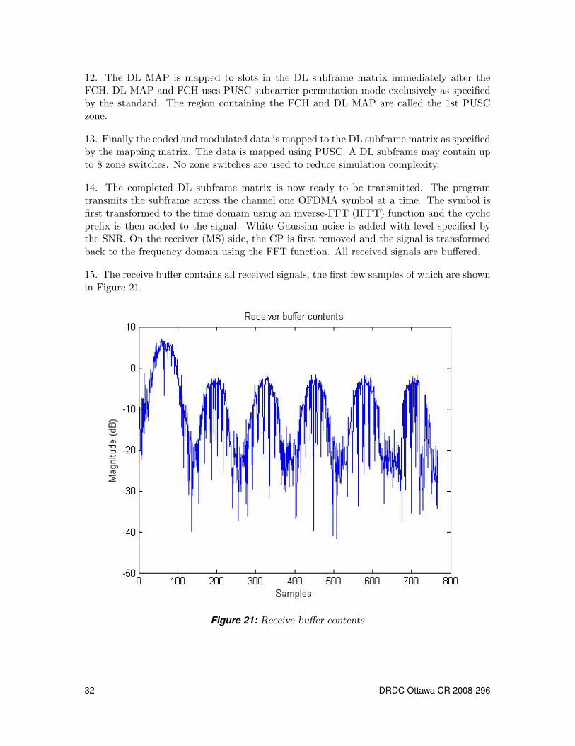
14. The completed DL subframe matrix is now ready to be transmitted. The programtransmits the subframe across the channel one OFDMA symbol at a time. The symbol isfirst transformed to the time domain using an inverse-FFT (IFFT) function and the cyclicprefix is then added to the signal. White Gaussian noise is added with level specified bythe SNR. On the receiver (MS) side, the CP is first removed and the signal is transformedback to the frequency domain using the FFT function. All received signals are buffered.
15. The receive buffer contains all received signals, the first few samples of which are shownin Figure 21.
Figure 21: Receive buffer contents
32 DRDC Ottawa CR 2008-296
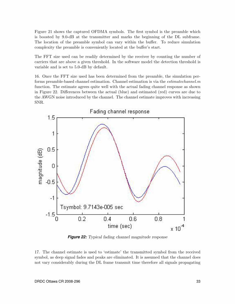
Figure 21 shows the captured OFDMA symbols. The first symbol is the preamble whichis boosted by 9.0-dB at the transmitter and marks the beginning of the DL subframe.The location of the preamble symbol can vary within the buffer. To reduce simulationcomplexity the preamble is conveniently located at the buffer’s start.
The FFT size used can be readily determined by the receiver by counting the number ofcarriers that are above a given threshold. In the software model the detection threshold isvariable and is set to 5.0-dB by default.
16. Once the FFT size used has been determined from the preamble, the simulation per-forms preamble-based channel estimation. Channel estimation is via the estimatechannel.mfunction. The estimate agrees quite well with the actual fading channel response as shownin Figure 22. Differences between the actual (blue) and estimated (red) curves are due tothe AWGN noise introduced by the channel. The channel estimate improves with increasingSNR.
Figure 22: Typical fading channel magnitude response
17. The channel estimate is used to ‘estimate’ the transmitted symbol from the receivedsymbol, as deep signal fades and peaks are eliminated. It is assumed that the channel doesnot vary considerably during the DL frame transmit time therefore all signals propagating
DRDC Ottawa CR 2008-296 33
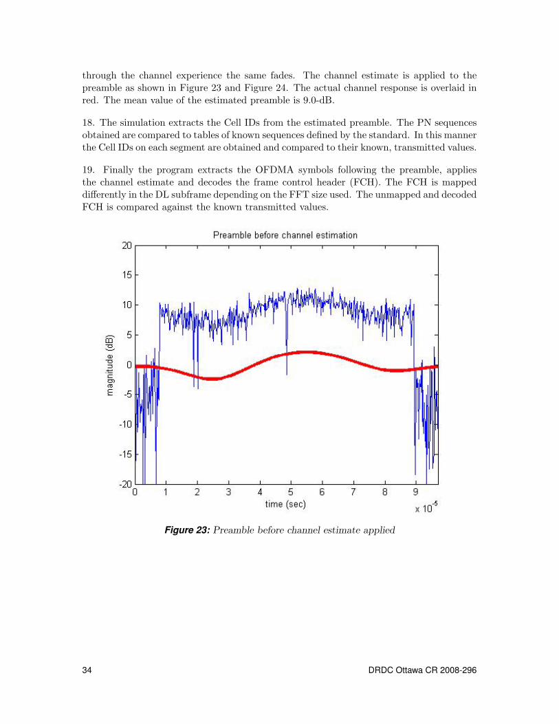
through the channel experience the same fades. The channel estimate is applied to thepreamble as shown in Figure 23 and Figure 24. The actual channel response is overlaid inred. The mean value of the estimated preamble is 9.0-dB.
18. The simulation extracts the Cell IDs from the estimated preamble. The PN sequencesobtained are compared to tables of known sequences defined by the standard. In this mannerthe Cell IDs on each segment are obtained and compared to their known, transmitted values.
19. Finally the program extracts the OFDMA symbols following the preamble, appliesthe channel estimate and decodes the frame control header (FCH). The FCH is mappeddifferently in the DL subframe depending on the FFT size used. The unmapped and decodedFCH is compared against the known transmitted values.
Figure 23: Preamble before channel estimate applied
34 DRDC Ottawa CR 2008-296
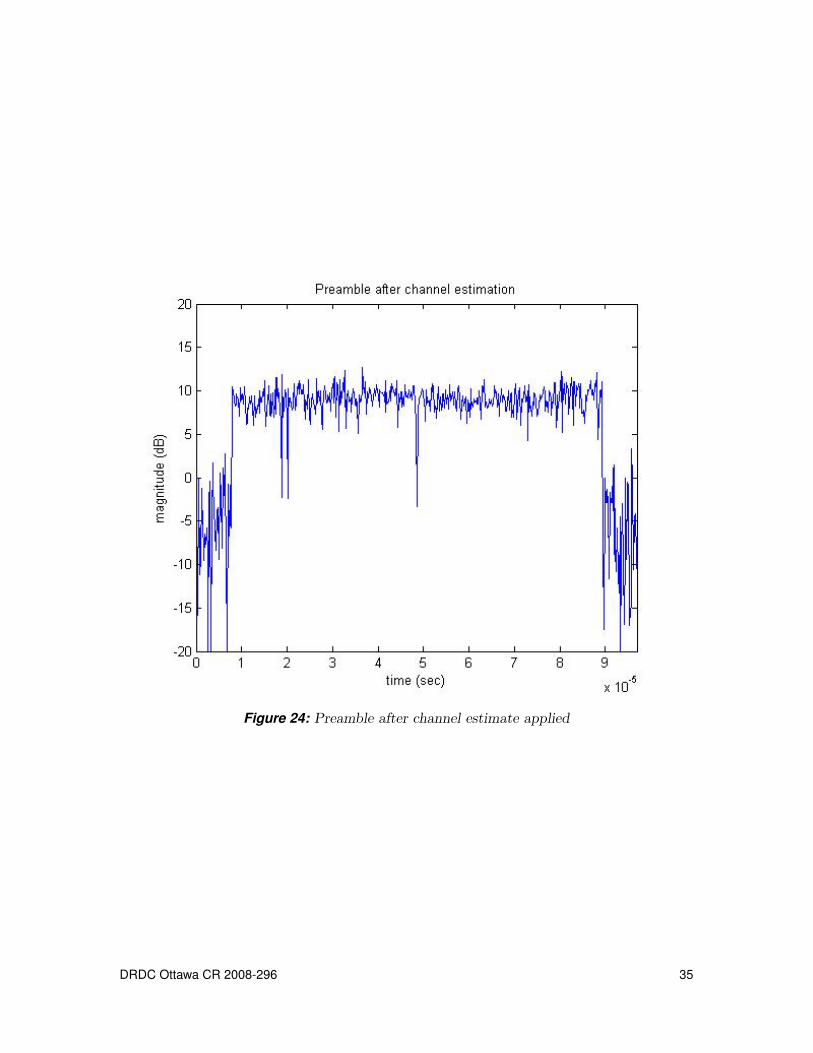
Figure 24: Preamble after channel estimate applied
DRDC Ottawa CR 2008-296 35
3.3.3 Program execution
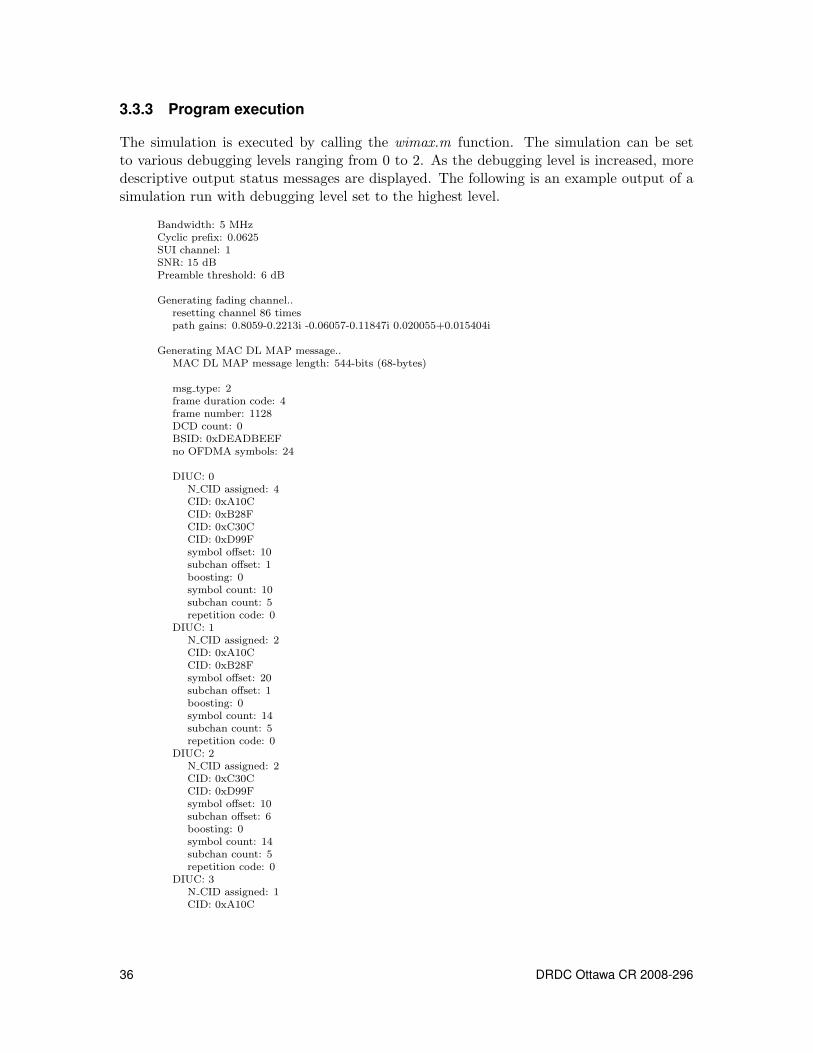
The simulation is executed by calling the wimax.m function. The simulation can be setto various debugging levels ranging from 0 to 2. As the debugging level is increased, moredescriptive output status messages are displayed. The following is an example output of asimulation run with debugging level set to the highest level.
Bandwidth: 5 MHzCyclic prefix: 0.0625SUI channel: 1SNR: 15 dBPreamble threshold: 6 dB
Generating fading channel..resetting channel 86 timespath gains: 0.8059-0.2213i -0.06057-0.11847i 0.020055+0.015404i
Generating MAC DL MAP message..MAC DL MAP message length: 544-bits (68-bytes)
msg type: 2frame duration code: 4frame number: 1128DCD count: 0BSID: 0xDEADBEEFno OFDMA symbols: 24
DIUC: 0N CID assigned: 4CID: 0xA10CCID: 0xB28FCID: 0xC30CCID: 0xD99Fsymbol offset: 10subchan offset: 1boosting: 0symbol count: 10subchan count: 5repetition code: 0
DIUC: 1N CID assigned: 2CID: 0xA10CCID: 0xB28Fsymbol offset: 20subchan offset: 1boosting: 0symbol count: 14subchan count: 5repetition code: 0
DIUC: 2N CID assigned: 2CID: 0xC30CCID: 0xD99Fsymbol offset: 10subchan offset: 6boosting: 0symbol count: 14subchan count: 5repetition code: 0
DIUC: 3N CID assigned: 1CID: 0xA10C
36 DRDC Ottawa CR 2008-296
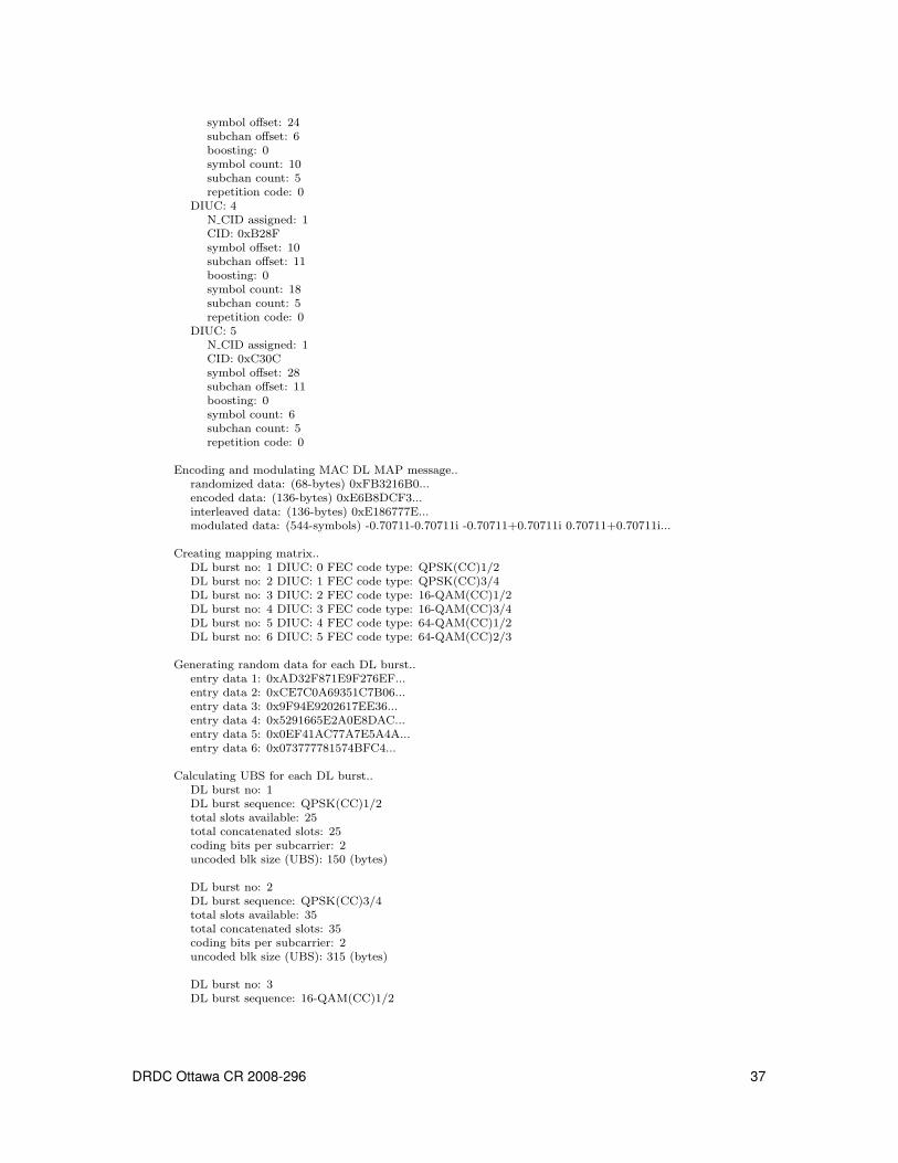
symbol offset: 24subchan offset: 6boosting: 0symbol count: 10subchan count: 5repetition code: 0
DIUC: 4N CID assigned: 1CID: 0xB28Fsymbol offset: 10subchan offset: 11boosting: 0symbol count: 18subchan count: 5repetition code: 0
DIUC: 5N CID assigned: 1CID: 0xC30Csymbol offset: 28subchan offset: 11boosting: 0symbol count: 6subchan count: 5repetition code: 0
Encoding and modulating MAC DL MAP message..randomized data: (68-bytes) 0xFB3216B0...encoded data: (136-bytes) 0xE6B8DCF3...interleaved data: (136-bytes) 0xE186777E...modulated data: (544-symbols) -0.70711-0.70711i -0.70711+0.70711i 0.70711+0.70711i...
Creating mapping matrix..DL burst no: 1 DIUC: 0 FEC code type: QPSK(CC)1/2DL burst no: 2 DIUC: 1 FEC code type: QPSK(CC)3/4DL burst no: 3 DIUC: 2 FEC code type: 16-QAM(CC)1/2DL burst no: 4 DIUC: 3 FEC code type: 16-QAM(CC)3/4DL burst no: 5 DIUC: 4 FEC code type: 64-QAM(CC)1/2DL burst no: 6 DIUC: 5 FEC code type: 64-QAM(CC)2/3
Generating random data for each DL burst..entry data 1: 0xAD32F871E9F276EF...entry data 2: 0xCE7C0A69351C7B06...entry data 3: 0x9F94E9202617EE36...entry data 4: 0x5291665E2A0E8DAC...entry data 5: 0x0EF41AC77A7E5A4A...entry data 6: 0x073777781574BFC4...
Calculating UBS for each DL burst..DL burst no: 1DL burst sequence: QPSK(CC)1/2total slots available: 25total concatenated slots: 25coding bits per subcarrier: 2uncoded blk size (UBS): 150 (bytes)
DL burst no: 2DL burst sequence: QPSK(CC)3/4total slots available: 35total concatenated slots: 35coding bits per subcarrier: 2uncoded blk size (UBS): 315 (bytes)
DL burst no: 3DL burst sequence: 16-QAM(CC)1/2
DRDC Ottawa CR 2008-296 37
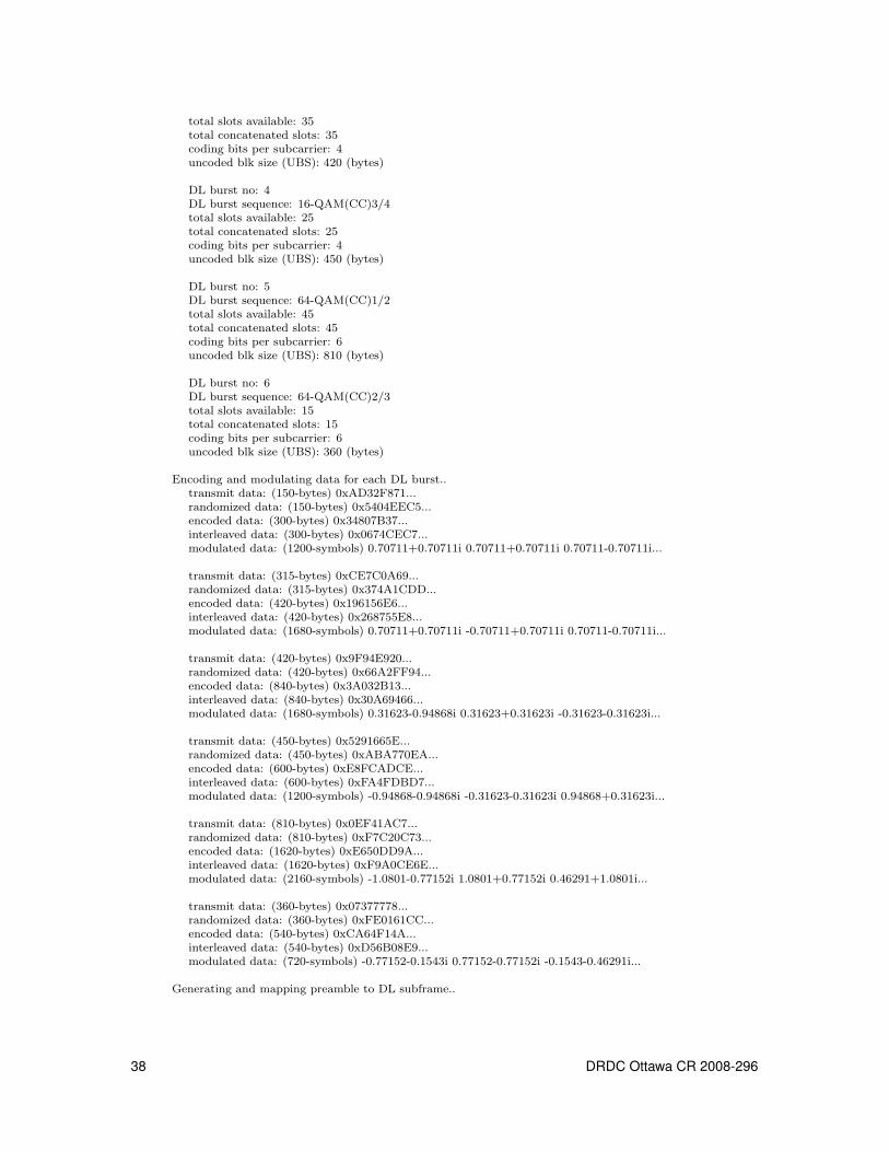
total slots available: 35total concatenated slots: 35coding bits per subcarrier: 4uncoded blk size (UBS): 420 (bytes)
DL burst no: 4DL burst sequence: 16-QAM(CC)3/4total slots available: 25total concatenated slots: 25coding bits per subcarrier: 4uncoded blk size (UBS): 450 (bytes)
DL burst no: 5DL burst sequence: 64-QAM(CC)1/2total slots available: 45total concatenated slots: 45coding bits per subcarrier: 6uncoded blk size (UBS): 810 (bytes)
DL burst no: 6DL burst sequence: 64-QAM(CC)2/3total slots available: 15total concatenated slots: 15coding bits per subcarrier: 6uncoded blk size (UBS): 360 (bytes)
Encoding and modulating data for each DL burst..transmit data: (150-bytes) 0xAD32F871...randomized data: (150-bytes) 0x5404EEC5...encoded data: (300-bytes) 0x34807B37...interleaved data: (300-bytes) 0x0674CEC7...modulated data: (1200-symbols) 0.70711+0.70711i 0.70711+0.70711i 0.70711-0.70711i...
transmit data: (315-bytes) 0xCE7C0A69...randomized data: (315-bytes) 0x374A1CDD...encoded data: (420-bytes) 0x196156E6...interleaved data: (420-bytes) 0x268755E8...modulated data: (1680-symbols) 0.70711+0.70711i -0.70711+0.70711i 0.70711-0.70711i...
transmit data: (420-bytes) 0x9F94E920...randomized data: (420-bytes) 0x66A2FF94...encoded data: (840-bytes) 0x3A032B13...interleaved data: (840-bytes) 0x30A69466...modulated data: (1680-symbols) 0.31623-0.94868i 0.31623+0.31623i -0.31623-0.31623i...
transmit data: (450-bytes) 0x5291665E...randomized data: (450-bytes) 0xABA770EA...encoded data: (600-bytes) 0xE8FCADCE...interleaved data: (600-bytes) 0xFA4FDBD7...modulated data: (1200-symbols) -0.94868-0.94868i -0.31623-0.31623i 0.94868+0.31623i...
transmit data: (810-bytes) 0x0EF41AC7...randomized data: (810-bytes) 0xF7C20C73...encoded data: (1620-bytes) 0xE650DD9A...interleaved data: (1620-bytes) 0xF9A0CE6E...modulated data: (2160-symbols) -1.0801-0.77152i 1.0801+0.77152i 0.46291+1.0801i...
transmit data: (360-bytes) 0x07377778...randomized data: (360-bytes) 0xFE0161CC...encoded data: (540-bytes) 0xCA64F14A...interleaved data: (540-bytes) 0xD56B08E9...modulated data: (720-symbols) -0.77152-0.1543i 0.77152-0.77152i -0.1543-0.46291i...
Generating and mapping preamble to DL subframe..
38 DRDC Ottawa CR 2008-296
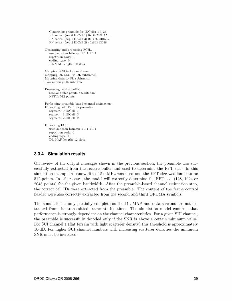
Generating preamble for IDCells: 1 3 28PN series: (seg 0 IDCell 1) 0xD8C30DA5...PN series: (seg 1 IDCell 3) 0xB027CB82...PN series: (seg 2 IDCell 28) 0x89B93046...
Generating and processing FCH..used subchan bitmap: 1 1 1 1 1 1repetition code: 0coding type: 0DL MAP length: 12 slots
Mapping FCH to DL subframe..Mapping DL MAP to DL subframe..Mapping data to DL subframe..Transmitting DL subframe..
Processing receive buffer..receive buffer points > 6-dB: 415NFFT: 512 points
Performing preamble-based channel estimation..Extracting cell IDs from preamble..
segment: 0 IDCell: 1segment: 1 IDCell: 3segment: 2 IDCell: 28
Extracting FCH..used subchan bitmap: 1 1 1 1 1 1repetition code: 0coding type: 0DL MAP length: 12 slots
3.3.4 Simulation results
On review of the output messages shown in the previous section, the preamble was suc-cessfully extracted from the receive buffer and used to determine the FFT size. In thissimulation example a bandwidth of 5.0-MHz was used and the FFT size was found to be512-points. In other cases, the model will correctly determine the FFT size (128, 1024 or2048 points) for the given bandwidth. After the preamble-based channel estimation step,the correct cell IDs were extracted from the preamble. The content of the frame controlheader were also correctly extracted from the second and third OFDMA symbols.
The simulation is only partially complete as the DL MAP and data streams are not ex-tracted from the transmitted frame at this time. The simulation model confirms thatperformance is strongly dependent on the channel characteristics. For a given SUI channel,the preamble is successfully decoded only if the SNR is above a certain minimum value.For SUI channel 1 (flat terrain with light scatterer density) this threshold is approximately10-dB. For higher SUI channel numbers with increasing scatterer densities the minimumSNR must be increased.
DRDC Ottawa CR 2008-296 39
4 Conclusion
During the 6-month period from 14 April to 14 November, 2008, five separate simulationmodels of the WiMAX PHY layer were produced with increasing complexity. The firstversion (V1) modeled a fixed WiMAX PHY layer based on the original IEEE802.16-2004standard. The first model was based on existing Matlab code in order to speed up develop-ment and gain fast understanding of the basic concepts involved. Important lessons werelearned that were applied to consecutive simulation versions.
During the second phase of development two software versions were produced. Version 2was an interim version. The third version (V3) of the simulation expanded on the originalmodel and incorporated several changes and corrections. The third version was also basedon a fixed WiMAX PHY layer and investigated the channel effects on the quality of atransmitted image. During development the focus was on understanding the differencesbetween the fixed and mobile WiMAX PHY layer as described by the IEEE802.16e-2005amendment to the original standard. A major improvement to the third version was theincorporation of an accurate channel estimation algorithm.
The first three simulation versions were basically an introduction to the key concepts andtechnologies used in the implementation of the WiMAX PHY layer. All of the lessonslearned were essential to the development of a mobile WiMAX PHY layer simulation com-pleted during the third phase. During the third phase of development two software versionswere produced. Version 4 was an interim version. Although the final version (V5) is incom-plete, it employs concepts basic to mobile WiMAX such as scalable OFDMA, subcarrierpermutation modes, sectorization, frame generation and preamble-based channel estima-tion techniques. Version 5 models the downlink and contains limited modeling of the MAClayer.
An important conclusion drawn from the V5 model is the susceptibility of the physicallayer to channel quality. As the receiver must first successfully capture, extract and decodethe transmitted frame preamble and other control messages, the simulation performanceis heavily dependent on the channel’s fading characteristics and random noise introducedinto the channel. Future simulation versions will focus on testing and evaluating systemperformance in various fading environments and operating modes.
The complete simulation model of the mobile WiMAX layer is far from complete. Futuresimulation version will incorporate other concepts such as adaptive modulation and coding(AMC), multiple-input multiple-output (MIMO), and will simulate the uplink.
40 DRDC Ottawa CR 2008-296
References
[1] IEEE (2004), IEEE Standard for Local and Metropolitan Area Networks,Number IEEE Std 802.16-2004 in Part 16: Air Interface for Fixed Broadband WirelessAccess Systems, IEEE, 3 Park Avenue, New York, NY 10016-5997, USA: IEEEComputer Society and the IEEE Microwave Theory and Techniques Society.
[2] IEEE (2006), IEEE Standard for Local and Metropolitan Area Networks,Number IEEE Std 802.16e-2005 and IEEE Std 802.16-2004/Cor1-2005 in Part 16: AirInterface for Fixed Broadband Wireless Access Systems Amendment 2: Physical andMedium Access Control Layers for Combined Fixed and Mobile Operation in LicensedBands and Corrigendum 1, IEEE, 3 Park Avenue, New York, NY 10016-5997, USA:IEEE Computer Society and the IEEE Microwave Theory and Techniques Society.
[3] IEEE (2001), Channel Models for Fixed Wireless Applications, Number IEEE802.16.3c-01/29r4, IEEE, IEEE 802.16 Broadband Wireless Access Working Group.
[4] Cai, Xiaodong and Giannakis, Georgios B. (2004), Error Probability Minimizing Pilotsfor OFDM with M-PSK Modulation over Rayleigh Fading Channels, IEEETransactions on Vehicular Technology, 53(1), 146–155.
[5] Jeffrey G. Andrews, Rias Muhamed, Arunabha Ghosh (2007), Fundamentals ofWiMAX - Understanding Broadband Wireless Networking, Prentice Hall.
[6] Byeong Gi Lee, Sunghyun Choi (2008), Broadband Wireless Access and LocalNetworks: Mobile WiMAX and WiFi, Artech House.
DRDC Ottawa CR 2008-296 41

This page intentionally left blank.
42 DRDC Ottawa CR 2008-296
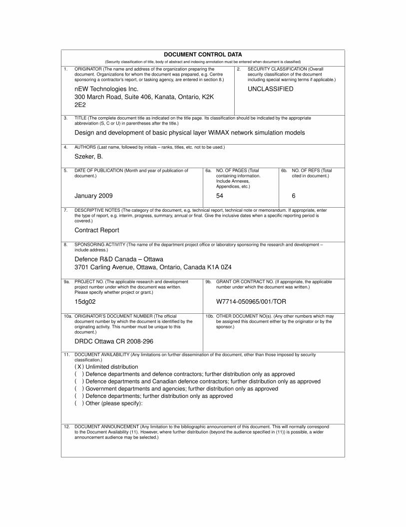
DOCUMENT CONTROL DATA(Security classification of title, body of abstract and indexing annotation must be entered when document is classified)
1. ORIGINATOR (The name and address of the organization preparing thedocument. Organizations for whom the document was prepared, e.g. Centresponsoring a contractor’s report, or tasking agency, are entered in section 8.)
nEW Technologies Inc.300 March Road, Suite 406, Kanata, Ontario, K2K2E2
2. SECURITY CLASSIFICATION (Overallsecurity classification of the documentincluding special warning terms if applicable.)
UNCLASSIFIED
3. TITLE (The complete document title as indicated on the title page. Its classification should be indicated by the appropriateabbreviation (S, C or U) in parentheses after the title.)
Design and development of basic physical layer WiMAX network simulation models
4. AUTHORS (Last name, followed by initials – ranks, titles, etc. not to be used.)
Szeker, B.
5. DATE OF PUBLICATION (Month and year of publication ofdocument.)
January 2009
6a. NO. OF PAGES (Totalcontaining information.Include Annexes,Appendices, etc.)
54
6b. NO. OF REFS (Totalcited in document.)
6
7. DESCRIPTIVE NOTES (The category of the document, e.g. technical report, technical note or memorandum. If appropriate, enterthe type of report, e.g. interim, progress, summary, annual or final. Give the inclusive dates when a specific reporting period iscovered.)
Contract Report
8. SPONSORING ACTIVITY (The name of the department project office or laboratory sponsoring the research and development –include address.)
Defence R&D Canada – Ottawa3701 Carling Avenue, Ottawa, Ontario, Canada K1A 0Z4
9a. PROJECT NO. (The applicable research and developmentproject number under which the document was written.Please specify whether project or grant.)
15dg02
9b. GRANT OR CONTRACT NO. (If appropriate, the applicablenumber under which the document was written.)
W7714-050965/001/TOR
10a. ORIGINATOR’S DOCUMENT NUMBER (The officialdocument number by which the document is identified by theoriginating activity. This number must be unique to thisdocument.)
DRDC Ottawa CR 2008-296
10b. OTHER DOCUMENT NO(s). (Any other numbers which maybe assigned this document either by the originator or by thesponsor.)
11. DOCUMENT AVAILABILITY (Any limitations on further dissemination of the document, other than those imposed by securityclassification.)( X ) Unlimited distribution( ) Defence departments and defence contractors; further distribution only as approved( ) Defence departments and Canadian defence contractors; further distribution only as approved( ) Government departments and agencies; further distribution only as approved( ) Defence departments; further distribution only as approved( ) Other (please specify):
12. DOCUMENT ANNOUNCEMENT (Any limitation to the bibliographic announcement of this document. This will normally correspondto the Document Availability (11). However, where further distribution (beyond the audience specified in (11)) is possible, a widerannouncement audience may be selected.)
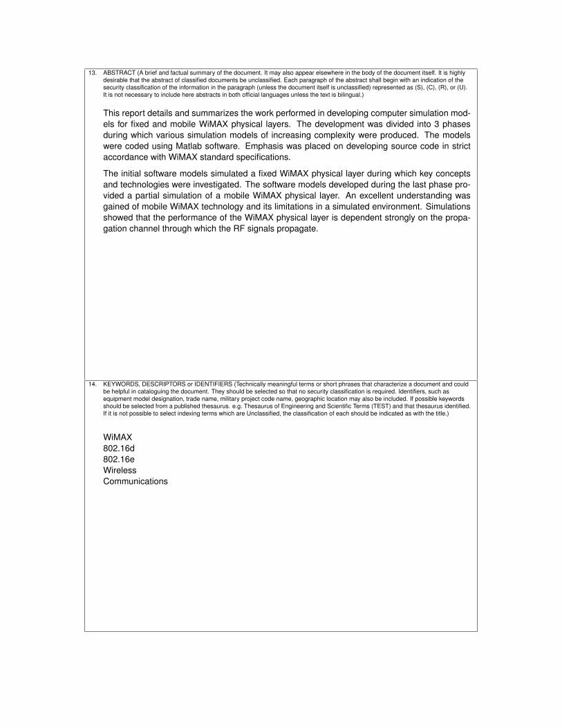
13. ABSTRACT (A brief and factual summary of the document. It may also appear elsewhere in the body of the document itself. It is highlydesirable that the abstract of classified documents be unclassified. Each paragraph of the abstract shall begin with an indication of thesecurity classification of the information in the paragraph (unless the document itself is unclassified) represented as (S), (C), (R), or (U).It is not necessary to include here abstracts in both official languages unless the text is bilingual.)
This report details and summarizes the work performed in developing computer simulation mod-els for fixed and mobile WiMAX physical layers. The development was divided into 3 phasesduring which various simulation models of increasing complexity were produced. The modelswere coded using Matlab software. Emphasis was placed on developing source code in strictaccordance with WiMAX standard specifications.
The initial software models simulated a fixed WiMAX physical layer during which key conceptsand technologies were investigated. The software models developed during the last phase pro-vided a partial simulation of a mobile WiMAX physical layer. An excellent understanding wasgained of mobile WiMAX technology and its limitations in a simulated environment. Simulationsshowed that the performance of the WiMAX physical layer is dependent strongly on the propa-gation channel through which the RF signals propagate.
14. KEYWORDS, DESCRIPTORS or IDENTIFIERS (Technically meaningful terms or short phrases that characterize a document and couldbe helpful in cataloguing the document. They should be selected so that no security classification is required. Identifiers, such asequipment model designation, trade name, military project code name, geographic location may also be included. If possible keywordsshould be selected from a published thesaurus. e.g. Thesaurus of Engineering and Scientific Terms (TEST) and that thesaurus identified.If it is not possible to select indexing terms which are Unclassified, the classification of each should be indicated as with the title.)
WiMAX802.16d802.16eWirelessCommunications