Embed Size (px)
Citation preview
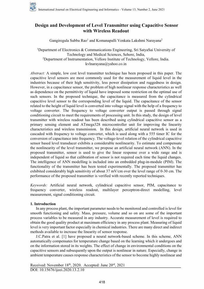
International Journal on Electrical Engineering and Informatics - Volume 13, Number 2, June 2021
Design and Development of Level Transmitter using Capacitive Sensor with Wireless Readout
Gangiregula Subba Rao1 and Komanapalli Venkata Lakshmi Narayana2
1Department of Electronics & Communications Engineering, Sri SatyaSai University of Technology and Medical Sciences, Sehore, India,
2Department of Instrumentation, Vellore Institute of Technology, Vellore, India. [email protected]
Abstract: A simple, low cost level transmitter technique has been proposed in this paper. The capacitive level sensors are most commonly used for the measurement of liquid level in the industries because of their high sensitivity, less power dissipation and ruggedness in design. However, in a capacitance sensor, the problem of high nonlinear response characteristics as well as dependence on the permittivity of liquid have imposed some restriction on the optimal use of such sensors. In the proposed technique, the capacitance is measured from the cylindrical capacitive level sensor to the corresponding level of the liquid. The capacitance of the sensor related to the height of liquid level is converted into voltage signal with the help of a frequency to voltage converter. The frequency to voltage converter output is passed through signal conditioning circuit to meet the requirements of processing unit. In this study, the design of level transmitter with wireless readout has been described using cylindrical capacitive sensor as a primary sensing element and ATmega328 microcontroller unit for improving the linearity characteristics and wireless transmission. In this design, artificial neural network is used in cascaded with frequency to voltage converter, which is used along with a 555 timer IC for the conversion of capacitance into frequency. The voltage-level relation of the cylindrical capacitive sensor based level transducer exhibits a considerable nonlinearity. To estimate and compensate the nonlinearity of the level transmitter, we propose an artificial neural network (ANN). In the proposed transmitter, sensor is used to give the linear response over a wide range and is independent of liquid so that calibration of sensor is not required each time the liquid changes. The intelligence of ANN modelling is included into an embedded plug-in-module (PIM). The functionality of the transmitter has been tested experimentally. The proposed transmitter has exhibited considerably high sensitivity of about 37 mV/cm over the level range of 0-30 cm. The performance of the proposed transmitter is verified with recently reported techniques.
Keywords: Artificial neural network, cylindrical capacitive sensor, PIM, capacitance to frequency converter, wireless readout, multilayer perceptron-direct modelling, level measurement, signal conditioning circuit.
1. IntroductionIn any process plant, the important parameter needs to be monitored and controlled is level for
smooth functioning and safety. Mass, pressure, volume and so on are some of the important process variables to be measured in any industry. Accurate measurement of level is required to obtain the good quality product at maximum efficiency in any process plant. Measuring of liquid level is very important factor especially in chemical industries. There are many direct and indirect methods available to increase the linearity of sensor response.
J.C.Patra et al. [1] have proposed a neural network-based scheme. In this scheme, ANNautomatically compensates for temperature change based on the learning which it undergoes and on the information stored in its weights. The effect of change in environmental conditions on the capacitive sensors and subsequently upon the output is nonlinear in nature. Especially, change in ambient temperature causes response characteristics of the sensor to become highly nonlinear and
Received: November 18th, 2020. Accepted: June 20rd, 2021 DOI: 10.15676/ijeei.2020.13.2.10
418
complex signal processing may be required to obtain correct readout. The purpose of direct modelling is to obtain an ANN model of the sensor in such a way that the outputs of the sensor and the ANN match closely. ANN model has been found to be capable of accurately estimating at any ambient temperature from 20 oC to 70 oC. This fact is the novel characteristic of the proposed ANN model. Capacitive sensors [2] electronically measure the capacitance between two or more conductors in a dielectric environment, usually air or a liquid. These sensors can directly sense a variety of things—motion, chemical composition, electric field—and indirectly, sense many other variables which can be converted into motion or dielectric constant, such as pressure, acceleration, fluid level, and fluid composition. Cylindrical capacitive sensor had been originally introduced by Chapman [3] for its advantages, which are the insensitivity to geometric errors by the averaging effect, which is derived from a simple intuition that the summation of geometric errors eventually converges to zero since the mean of geometric errors is zero and the high resolution with large sensing area compared to probe-type sensors. In any process industry, liquid such as water, chemicals, and solvents in a storage vessel is required to be measured and controlled. The amount of such liquid stored can be found by measuring liquid level in a container or vessel. The liquid level affects the quantity delivered in and out of the container. The pressure and flow rate of liquid affects the liquid level of the container. The change in capacitance of a capacitive sensor due to a change in process variable is generally very small. Hence, various attempts have been made by different researchers [4]–[18] to accurately measure this change in capacitance. In the conventional bridge methods, the Schering bridge [12] is best suited for the measurement of capacitance but the bridge methods are tedious and time consuming, as convergence toward balance requires several iterative steps. Automatic balancing bridges [13]–[15] have been developed but with increased complexity and cost. The direct-reading technique of capacitance measurement reported in [16] though useful, requires involved computation for determining the parameters from measured voltages. The microprocessor based switched battery capacitance meter proposed in [17] is simple, but the measured values do not reflect the accepted equivalent circuit parameters applicable to sinusoidal excitation. In the method reported [18], the unknown capacitance changes the frequency of an oscillator and the frequency deviation is used as a measure of the capacitance. A new method of measuring capacitance, using oscillator circuits [19] requires a standard capacitor of value nearly equal to that of the nominal value of the unknown capacitor. The above two methods have a limitation that the unknown capacitor cannot be tested at a desired frequency and voltage. A simple scheme for the measurement of capacitance and dissipation factor of capacitor proposed in [20] has less resolution and hence it is not suitable for low value capacitance measurement. In this scheme, the accuracy of the prototype unit for the measurement of capacitance has been found as ±0.2%.Hence, it is aimed to improve the linearity of capacitance measuring circuit of about ±0.1% and to compensate the stray and parasitic capacitances exist in the capacitive sensor, capacitance measuring circuit. A parallel stream of developmental activities is focused on numerical methods for sensor linearization. A piecewise linearization method for thermistor is reported in [8]. It overcomes the limitations of the lookup table (LUT) technique. Few curve fitting methods such as spline, polynomial, progressive polynomial, improved progressive polynomial and modified progressive polynomial have been introduced for sensor linearization. ANN based linearization techniques have been proposed for various sensors [9-11]. Although these methods provide improved accuracy and simple implementation, requires a precise calibration with large number of data points to cover the complete operating range of the given sensor, which is a difficult and time-consuming task. Moreover, sensor resolution and data noise limit the efficiency in experimental process. The number of calibration points and their selection affect the performance
Gangiregula Subba Rao, et al
419
of these methods. A high degree of polynomial function is necessary in these methods which increases the computational load. An effective signal conditioning circuit suffers from stray effects, ambient factors, component tolerances and ageing in the conventional design of transmitters. Hence the signal conditioning circuit with the integration of intelligent capabilities through soft computing techniques is a potential solution for continuous monitoring, wireless transmission and digital readout as well as on-chip interface. Software based methods have been reported for linearization, error minimization and cross sensitivity error reduction and so on. The use of LUT requires a special read only memory for storing sensor data which is an important problem in some microprocessor and microcontroller-based systems. ANN based techniques yield better results than the classical electronic techniques. Analog and digital systems can be used to implement neural networks. In this paper, a wireless level measurement technique using cylindrical capacitive sensor is proposed. The applied level is converted into linearized voltage using signal conditioning circuit and ANN. The resultant voltage is transmitted in the wireless medium using GSM module. 2. Method of Approach 2.1 Theory The change in capacitance, with respect to the liquid column of height, h1 and remaining height, h2 of the metallic tank with air as the dielectric is given by (1) [26]
1 1 2 1
2
1
[ ( )]
ln( )02C= h L h
rr
πε ε ε+ −∆
(1) where h1 is the height of liquid column, L is length of the cylindrical capacitor, r1 is the radius of solid cylindrical conductor, r2 is the inner radius of coaxial cylindrical shell and є0, є1 and є2 are the permittivity of free space, liquid and air respectively.
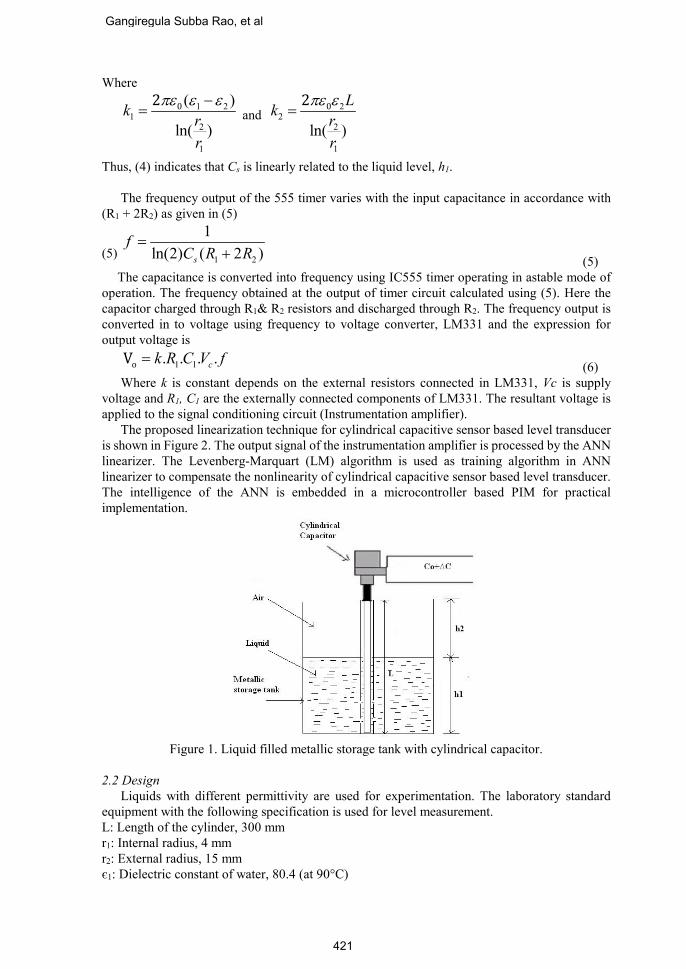
The cylindrical capacitor immersed in the liquid filled metallic storage tank and it touches the metallic storage tank as shown in Figure 1. The inner conductive cylinder of the capacitive sensor is filled with the air. There is another capacitance C0 between the metallic storage tank or other metallic objects and the cylindrical capacitor. This capacitance may be assumed to be the parallel combination of parasitic capacitances exists: between metallic vessel and upper part of the probe above the liquid level; between metallic vessel and lower part of the probe below the liquid level. This capacitance in the order of pF may be assumed to be connected in parallel with the test capacitance between the liquid column of height h1 and the sensing probe. The stray capacitance which exists between the electrodes and measuring circuit is independent of liquid level to be measured. It alters the effective values of measuring circuit components. The effective capacitance of the sensor consists of the parasitic and stray capacitances. Hence, the effective capacitance of the sensing probe, Cs with respect to the liquid column of height h1, may be given by
0sC C C= + ∆ (2) Combining (1) and (2), we have
1 1 2 10
2
1
[ ( )]
ln( )02
sh L hC C r
r
πε ε ε+ −= +
(3) or
1 1 2 0sC k h k C= + + (4)
Design and Development of Level Transmitter using Capacitive Sensor
420
Where
1 21
2
1
( )
ln( )02k r
r
πε ε ε−=
and 2
22
1
ln( )02 Lk rr
πε ε=
Thus, (4) indicates that Cs is linearly related to the liquid level, h1. The frequency output of the 555 timer varies with the input capacitance in accordance with (R1 + 2R2) as given in (5)
1 2
1ln(2) ( 2 )s
fC R R
=+ (5)
(5)
The capacitance is converted into frequency using IC555 timer operating in astable mode of operation. The frequency obtained at the output of timer circuit calculated using (5). Here the capacitor charged through R1& R2 resistors and discharged through R2. The frequency output is converted in to voltage using frequency to voltage converter, LM331 and the expression for output voltage is
1 1. . . .oV ck R C V f= (6) Where k is constant depends on the external resistors connected in LM331, Vc is supply voltage and R1, C1 are the externally connected components of LM331. The resultant voltage is applied to the signal conditioning circuit (Instrumentation amplifier). The proposed linearization technique for cylindrical capacitive sensor based level transducer is shown in Figure 2. The output signal of the instrumentation amplifier is processed by the ANN linearizer. The Levenberg-Marquart (LM) algorithm is used as training algorithm in ANN linearizer to compensate the nonlinearity of cylindrical capacitive sensor based level transducer. The intelligence of the ANN is embedded in a microcontroller based PIM for practical implementation.
Figure 1. Liquid filled metallic storage tank with cylindrical capacitor.
2.2 Design Liquids with different permittivity are used for experimentation. The laboratory standard equipment with the following specification is used for level measurement. L: Length of the cylinder, 300 mm r1: Internal radius, 4 mm r2: External radius, 15 mm є1: Dielectric constant of water, 80.4 (at 90°C)
Gangiregula Subba Rao, et al
421
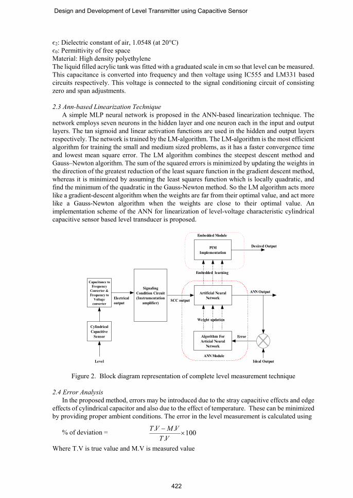
є2: Dielectric constant of air, 1.0548 (at 20°C) є0: Permittivity of free space Material: High density polyethylene The liquid filled acrylic tank was fitted with a graduated scale in cm so that level can be measured. This capacitance is converted into frequency and then voltage using IC555 and LM331 based circuits respectively. This voltage is connected to the signal conditioning circuit of consisting zero and span adjustments. 2.3 Ann-based Linearization Technique A simple MLP neural network is proposed in the ANN-based linearization technique. The network employs seven neurons in the hidden layer and one neuron each in the input and output layers. The tan sigmoid and linear activation functions are used in the hidden and output layers respectively. The network is trained by the LM-algorithm. The LM-algorithm is the most efficient algorithm for training the small and medium sized problems, as it has a faster convergence time and lowest mean square error. The LM algorithm combines the steepest descent method and Gauss–Newton algorithm. The sum of the squared errors is minimized by updating the weights in the direction of the greatest reduction of the least square function in the gradient descent method, whereas it is minimized by assuming the least squares function which is locally quadratic, and find the minimum of the quadratic in the Gauss-Newton method. So the LM algorithm acts more like a gradient-descent algorithm when the weights are far from their optimal value, and act more like a Gauss-Newton algorithm when the weights are close to their optimal value. An implementation scheme of the ANN for linearization of level-voltage characteristic cylindrical capacitive sensor based level transducer is proposed.
Capacitance toFrequency
Converter &Frequency to
Voltageconverter
SignalingCondition Circuit(Instrumentation
amplifier)
Artificial NeuralNetwork
PIMImplementation
Algorithm ForArticial Neural
Network
Electricaloutput SCC output
Embedded learning
Weight updation
ANN Module
Embedded Module
ANN Output
Ideal Output
Error
Desired Output
CylindricalCapacitive
Sensor
Level
Figure 2. Block diagram representation of complete level measurement technique
2.4 Error Analysis In the proposed method, errors may be introduced due to the stray capacitive effects and edge effects of cylindrical capacitor and also due to the effect of temperature. These can be minimized by providing proper ambient conditions. The error in the level measurement is calculated using
% of deviation = Where T.V is true value and M.V is measured value
. . 100.
T V M VT V−
×
Design and Development of Level Transmitter using Capacitive Sensor
422
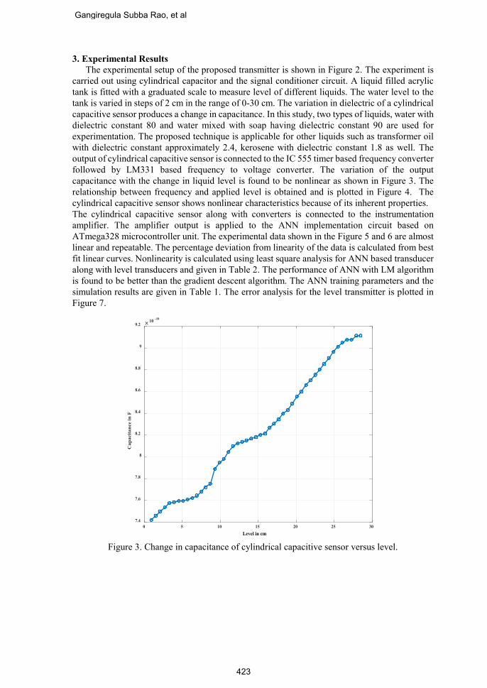
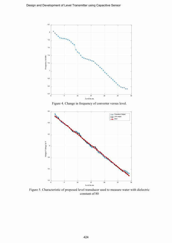
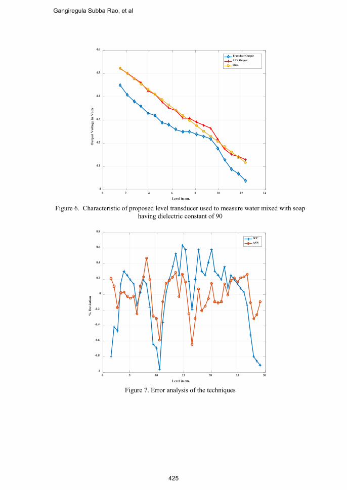
3. Experimental Results The experimental setup of the proposed transmitter is shown in Figure 2. The experiment is carried out using cylindrical capacitor and the signal conditioner circuit. A liquid filled acrylic tank is fitted with a graduated scale to measure level of different liquids. The water level to the tank is varied in steps of 2 cm in the range of 0-30 cm. The variation in dielectric of a cylindrical capacitive sensor produces a change in capacitance. In this study, two types of liquids, water with dielectric constant 80 and water mixed with soap having dielectric constant 90 are used for experimentation. The proposed technique is applicable for other liquids such as transformer oil with dielectric constant approximately 2.4, kerosene with dielectric constant 1.8 as well. The output of cylindrical capacitive sensor is connected to the IC 555 timer based frequency converter followed by LM331 based frequency to voltage converter. The variation of the output capacitance with the change in liquid level is found to be nonlinear as shown in Figure 3. The relationship between frequency and applied level is obtained and is plotted in Figure 4. The cylindrical capacitive sensor shows nonlinear characteristics because of its inherent properties. The cylindrical capacitive sensor along with converters is connected to the instrumentation amplifier. The amplifier output is applied to the ANN implementation circuit based on ATmega328 microcontroller unit. The experimental data shown in the Figure 5 and 6 are almost linear and repeatable. The percentage deviation from linearity of the data is calculated from best fit linear curves. Nonlinearity is calculated using least square analysis for ANN based transducer along with level transducers and given in Table 2. The performance of ANN with LM algorithm is found to be better than the gradient descent algorithm. The ANN training parameters and the simulation results are given in Table 1. The error analysis for the level transmitter is plotted in Figure 7.
0 5 10 15 20 25 30Level in cm
7.4
7.6
7.8
8
8.2
8.4
8.6
8.8
9
9.2
Cap
acita
nce
in F
10 -10
Figure 3. Change in capacitance of cylindrical capacitive sensor versus level.
Gangiregula Subba Rao, et al
423
0 5 10 15 20 25 30
Level in cm.
6.4
6.6
6.8
7
7.2
7.4
7.6
7.8
8
8.2
Freq
uenc
y in
kH
z
Figure 4. Change in frequency of converter versus level.
0 5 10 15 20 25 30
Level in cm.
3.4
3.6
3.8
4
4.2
4.4
4.6
Out
put V
olta
ge in
V
Transducer OutputANN outputIdeal
Figure 5. Characteristic of proposed level transducer used to measure water with dielectric
constant of 80
Design and Development of Level Transmitter using Capacitive Sensor
424
0 2 4 6 8 10 12 14
Level in cm.
4
4.1
4.2
4.3
4.4
4.5
4.6
Out
put V
olta
ge in
Vol
ts
Transduer OutputANN OutputIdeal
Figure 6. Characteristic of proposed level transducer used to measure water mixed with soap
having dielectric constant of 90
0 5 10 15 20 25 30
Level in cm.
-1
-0.8
-0.6
-0.4
-0.2
0
0.2
0.4
0.6
0.8
% D
evia
tion
SCCANN
Figure 7. Error analysis of the techniques
Gangiregula Subba Rao, et al
425
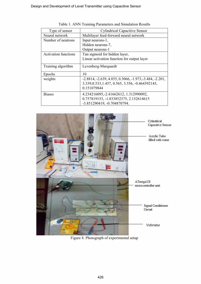
Table 1. ANN Training Parameters and Simulation Results
Figure 8. Photograph of experimental setup
Type of sensor Cylindrical Capacitive Sensor Neural network Multilayer feed-forward neural network Number of neutrons Input neurons-1,
Hidden neurons-7, Output neurons-1
Activation functions Tan sigmoid for hidden layer, Linear activation function for output layer
Training algorithm Levenberg-Marquardt
Epochs 10 weights -2.8814, -2.639, 4.855, 0.3066, -1.973,-3.484, -2.201,
3.339,0.533,1.457, 0.565, 3.556, -0.464392145, 0.151079844
Biases 4.234216095,-2.41662612, 1.312990092, 0.757819153, -1.833852375, 2.152614615 -3.851290419, -0.704870794.
Design and Development of Level Transmitter using Capacitive Sensor
426
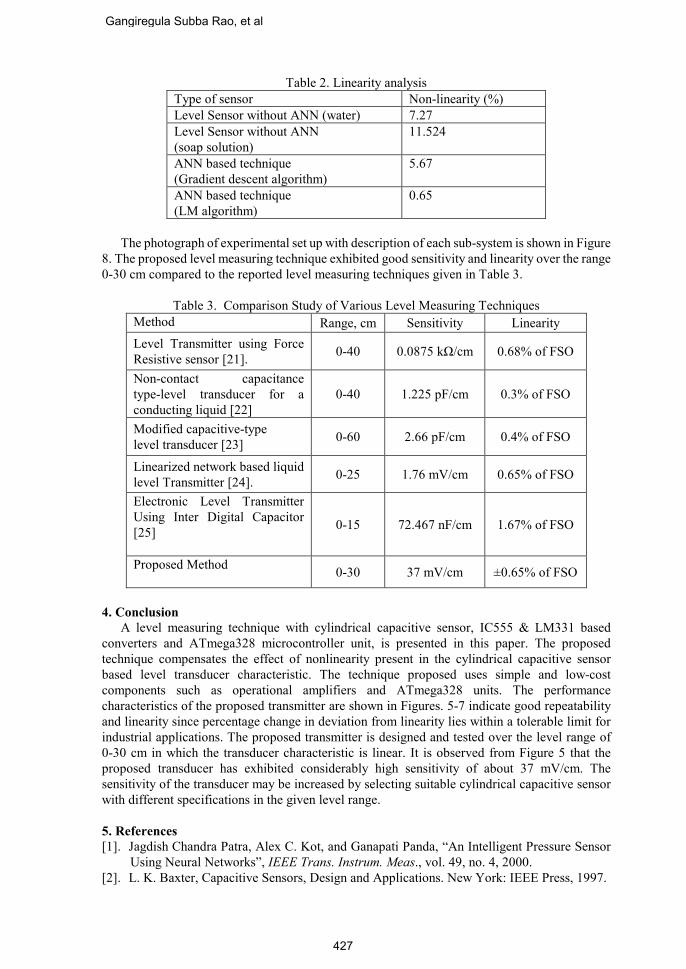
Table 2. Linearity analysis Type of sensor Non-linearity (%) Level Sensor without ANN (water) 7.27 Level Sensor without ANN (soap solution)
11.524
ANN based technique (Gradient descent algorithm)
5.67
ANN based technique (LM algorithm)
0.65
The photograph of experimental set up with description of each sub-system is shown in Figure 8. The proposed level measuring technique exhibited good sensitivity and linearity over the range 0-30 cm compared to the reported level measuring techniques given in Table 3.
Table 3. Comparison Study of Various Level Measuring Techniques Method Range, cm Sensitivity Linearity Level Transmitter using Force Resistive sensor [21]. 0-40 0.0875 kΩ/cm 0.68% of FSO
Non-contact capacitance type-level transducer for a conducting liquid [22]
0-40 1.225 pF/cm 0.3% of FSO
Modified capacitive-type level transducer [23] 0-60 2.66 pF/cm 0.4% of FSO
Linearized network based liquid level Transmitter [24]. 0-25 1.76 mV/cm 0.65% of FSO
Electronic Level Transmitter Using Inter Digital Capacitor [25]
0-15 72.467 nF/cm 1.67% of FSO
Proposed Method 0-30 37 mV/cm ±0.65% of FSO
4. Conclusion A level measuring technique with cylindrical capacitive sensor, IC555 & LM331 based converters and ATmega328 microcontroller unit, is presented in this paper. The proposed technique compensates the effect of nonlinearity present in the cylindrical capacitive sensor based level transducer characteristic. The technique proposed uses simple and low-cost components such as operational amplifiers and ATmega328 units. The performance characteristics of the proposed transmitter are shown in Figures. 5-7 indicate good repeatability and linearity since percentage change in deviation from linearity lies within a tolerable limit for industrial applications. The proposed transmitter is designed and tested over the level range of 0-30 cm in which the transducer characteristic is linear. It is observed from Figure 5 that the proposed transducer has exhibited considerably high sensitivity of about 37 mV/cm. The sensitivity of the transducer may be increased by selecting suitable cylindrical capacitive sensor with different specifications in the given level range. 5. References [1]. Jagdish Chandra Patra, Alex C. Kot, and Ganapati Panda, “An Intelligent Pressure Sensor
Using Neural Networks”, IEEE Trans. Instrum. Meas., vol. 49, no. 4, 2000. [2]. L. K. Baxter, Capacitive Sensors, Design and Applications. New York: IEEE Press, 1997.
Gangiregula Subba Rao, et al
427
[3]. P. D. Chapman, “A capacitive based ultra-precision spindle error analyzer”, J. Precision Eng., vol. 7, no. 3, pp. 129–137, 1985.
[4]. B. G. Liptak, Process Measurement and Analysis, Oxford, U.K, 1999. [5]. D. M. Considine, Process Instruments and Control Hand Book, McGraw-Hill, New York,
1974. [6]. A. J. Jaworski, T. Dyakowski, and G. A. Davies, “A capacitance probe for interface
detection in oil and gas extraction plant”, Meas. Sci.Technol., vol. 10, no. 3, pp. L15–L20, 1999.
[7]. W. R. Yang, M. R. Brant, and M. S. Beck, “A multi-interface level measurement system using a segmental capacitance sensor for oil separators”, Meas. Sci. Technol., vol. 5, no. 9, pp. 1177–1180, 1994.
[8]. S. M. Herang, R. G. Green, A. Plaskowski, and M. S. Beck, A high frequency stray immune capacitance transducer based on the charge transfer principle, IEEE Trans. Instrum Meas., vol.37, pp.373, 1998.
[9]. A. H. Falkner, The use of capacitance in the measurement of angular and linear displacement, IEEE Trans. Instrum. Meas, vol.43, pp.942, 1994.
[10]. P. Holmberg, Automatic balancing of linear AC bridge circuits for capacitive sensor elements, IEEE Trans. Instrum. Meas., vol.44 pp.805, 1995.
[11]. D. Marioli, E. Sardini, and A. Taroni, High accuracy measurement techniques for capacitance transducers, Meas. Sci. Technol. vol.4, pp.343, 1993.
[12]. Foley A.H, A direct reading high-voltage capacitance bridge Transactions of American institute of electrical engineers .vol.69 pp.698,1950.
[13]. O. Petersons, “A self-balancing high voltage capacitance bridge”, IEEE Trans. Instrum. Meas., vol.13, pp. 216–224, 1964.
[14]. O. Petersons and W. E. Anderson, “A wide-range high-voltage capacitance bridge with one ppm accuracy”, IEEE Trans. Instrum. Meas., vol.24, pp. 336–344, 1975.
[15]. R. D. Cutkosky, “An automatic high-precision audio frequency capacitance bridge”, IEEE Trans. Instrum. Meas., vol.34, pp. 383–389,1985.
[16]. M. S. Ansari and M. T. Ahmed, “A novel direct reading active-RC system for measurements of in-circuit, discrete, and incremental capacitances”, IEEE Tran. Instrum. Meas., vol.38, pp.922–992, 1989.
[17]. S. M. Mahmud and A. Rusek, “A microprocessor-based switched battery capacitance meter”, IEEE Trans. Instrum. Meas., vol. 37, pp.191–194, 1988.
[18]. T. Takagi and A. Yamakawa, “A simple and wide-range capacitance measuring equipment using transistor blocking oscillator”, IEEE Trans.Instrum. Meas., vol.25, pp.162–163, 1976.
[19]. S. Natarajan, Measurement of capacitance and their loss factors, IEEE Tran. Instrum. Meas., vol.38, pp.1087, 1989.
[20]. V. Jagadeesh Kumar, P. Sankaran, and K. Sudhakar Rao, “Measurement of C and tanδ of a capacitor employing PSDs and Dual-slope DVMs”, IEEE Trans. Instrum. Meas., vol. 52, no.5, pp. 1588–1592, 2003.
[21]. A. Lata, B. Kumar and N. Mandal, "Design and development of a level transmitter using force resistive sensor as a primary sensing element," in IET Science, Measurement & Technology, vol. 12, no. 1, pp. 118-125, 1 2018.
[22]. Chakraborty, S., Bera, S.K., Mandal, N., et al.: ‘Study on further modification of non-contact capacitance type-level transducer for a conducting liquid’, IEEE Sens. J., 2015, 15, (11), pp. 6678–6688.
[23]. Bera, S.C., Mandal, H., Saha, S., et al.: ‘Study of a modified capacitive-type level transducer for any type of liquid’, IEEE Trans. Instrum. Meas., 2014, 63, (3), pp. 641–649.
[24]. Marick, S., Bera, S.K., Bera, S.C.: ‘A float type liquid level measuring system using a modified inductive transducer’, Sens. Transducers J., 2014, 182, (11), pp. 111–118.
Design and Development of Level Transmitter using Capacitive Sensor
428
[25]. S. F. Ali and N. Mandal, "Design and Development of an Electronic Level Transmitter Using Inter Digital Capacitor," in IEEE Sensors Journal, vol. 19, no. 13, pp. 5179-5185, 1 July1, 2019.
[26]. A.K.Shawney, “A course in Electrical and Electronic measurement and Instrumentation”, Dhanpat Rai &Company, 18th Edition, 2010.
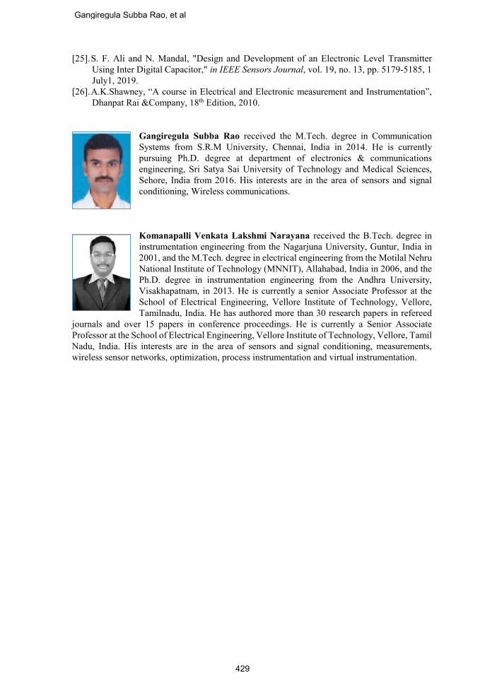
Gangiregula Subba Rao received the M.Tech. degree in Communication Systems from S.R.M University, Chennai, India in 2014. He is currently pursuing Ph.D. degree at department of electronics & communications engineering, Sri Satya Sai University of Technology and Medical Sciences, Sehore, India from 2016. His interests are in the area of sensors and signal conditioning, Wireless communications.
Komanapalli Venkata Lakshmi Narayana received the B.Tech. degree in instrumentation engineering from the Nagarjuna University, Guntur, India in 2001, and the M.Tech. degree in electrical engineering from the Motilal Nehru National Institute of Technology (MNNIT), Allahabad, India in 2006, and the Ph.D. degree in instrumentation engineering from the Andhra University, Visakhapatnam, in 2013. He is currently a senior Associate Professor at the School of Electrical Engineering, Vellore Institute of Technology, Vellore, Tamilnadu, India. He has authored more than 30 research papers in refereed
journals and over 15 papers in conference proceedings. He is currently a Senior Associate Professor at the School of Electrical Engineering, Vellore Institute of Technology, Vellore, Tamil Nadu, India. His interests are in the area of sensors and signal conditioning, measurements, wireless sensor networks, optimization, process instrumentation and virtual instrumentation.
Gangiregula Subba Rao, et al
429