Embed Size (px)
Citation preview
DESIGN AND DEVEPLOMENT OF MOTION
AND THERMAL CONTROLLER FOR
THERMAL FATIGUE MACHINE
MOHAMAD RIDHWAN SHAHRIL BIN
BAHARUDIN
Thesis submitted in partial fulfillment of the requirements
For the award of the degree of
B. Eng (Hons) Mechatronic Engineering
Faculty of Manufacturing Engineering
UNIVERSITI MALAYSIA PAHANG
June 2016
UNIVERSITI MALAYSIA PAHANG
DECLARATION OF THESIS AND COPYRIGHT
Author’s Full Name : MOHAMAD RIDHWAN SHAHRIL BIN
BAHARUDIN
Identification Card No : 930803-03-5153
Title : DESIGN AD DEVEPLOMENT OF MOTION
AND THERMAL CONTROLLER FOR
THERMAL FATIGUE MACHINE
I declare that this thesis is classified as:
CONFIDENTIAL
(Contains confidential information under the
Official Secret Act 1972)
RESTRICTED
(Contains restricted information as specified by
the organization where research was done)*
OPEN ACCESS
I agree that my thesis to be published as online
open access (Full text)
I acknowledge that University Malaysia Pahang reserve the right as follows:
1. The Thesis is the Property of University Malaysia Pahang.
2. The Library of University Malaysia Pahang has the right to make copies for the purpose
of research only.
3. The Library has the right to make copies of the thesis for academic exchange.
Certified by:
_____________________________ _____________________________
(Author’s Signature) (Supervisor’s Signature)
_________________________________
Name of Supervisor
Date: _______________ Date: ________________
ii
SUPERVISOR’S DECLARATION
I hereby declare that I have checked this project and in my opinion, this project is adequate in
terms of scope and quality for the award of the degree of Bachelor of Manufacturing
Engineering.
Signature :
Name of supervisor : Dr. IZWAN BIN ISMAIL
Position : Lecturer
Date : 21/6/2016
iii
STUDENT’S DECLARATION
I hereby declare that the work in this project is my own except for quotation and summaries
that have been duly acknowledged. The project has not been accepted for any degree and is
not concurrently submitted for award of other degree.
Signature :
Name : MOHAMMAD RIDHWAN SHAHRIL BIN BAHARUDIN
ID Number : FB12012
Date : 21/6/2016
viii
TABLE OF CONTENTS
Page
SUPERVISOR’S DECLARATION ii
STUDENT’S DECLARATION iii
ACKNOWLEDGEMENTS v
ABSTRACT vi
ABSTRAK vii
TABLE OF CONTENTS viii
LIST OF TABLES xii
LIST OF FIGURES xiii
LIST OF SYMBOLS xv
LIST OF SYMBOLS xvi
CHAPTER 1 INTRODUCTION
1.1 Project Background 1
1.2 Problem Statement 2
1.3 Objectives of the Research 3
1.4 Project Scope 3
ix
CHAPTER 2 LITERATURE REVIEW
2.1 Thermal Fatigue Testing Method 4
2.2 Programmable Logic Controller (PLC) 5
2.2.1 Ladder Diagram 8
2.2.2 PID Controller 9
2.3 Pneumatics System 9
2.3.1 Advantages and Disadvantages of Pneumatics System 10
2.3.2 Pneumatic Cylinder 11
2.4 Electrical Component 12
2.4.1 Temperature Controller 12
2.4.2 Solid State Relay (SSR) 13
2.4.3 Heating Element 15
CHAPTER 3 METHODOLOGY
3.1 Introduction 17
3.2 System Requirement Analysis Method 19
3.3 Design Thermal Controller and Pneumatic System 19
3.3.1 Pneumatic System Design 19
3.3.1.1 Linking Pneumatic System to The PLC 22
3.3.1.2 CX-Programmer 23
3.3.2 Thermal Controller Design 23
3.3.2.1 Lamp Pushbutton with Indicator 23
3.3.2.2 Ready Lamp 24
x
3.3.2.3 Buzzer 24
3.3.2.4 Switch for Silence Buzzer with Red Lamp 24
3.4 Furnace Temperature Control 24
3.4.1 Implementation of two solid state relay 26
3.5 Evaluate of Thermal Fatigue Testing Machine 26
CHAPTER 4 RESULTS AND DISCUSSION
4.1 Introduction 28
4.2 Hardware 28
4.2.1 Pneumatic System 28
4.2.2 Furnace Design 30
4.2.3 Heating Element 31
4.2.4 Furnace control Design 31
4.2.4.1 Temperature control 31
4.2.4.2 Furnace Circuit 32
4.2.4.5 Omron PLC 33
4.3 Software 34
4.3.1 CX-Programmer 34
4.4 Determination of Furnace Power 38
4.5 Pneumatic Cylinder Calculate Value 39
4.5.1 Actuator Cylinder 39
4.5.2 Rotary Cylinder 42
xi
4.6 Performance Evaluation for Thermal Fatigue Testing Machine 47
4.6.1 Testing Machine with Real Experiment 47
4.6.2 Pneumatic System Testing 49
CHAPTER 5 CONCLUSION AND RECOMMENDATION
5.1 Conclusion 48
5.2 Recommendation 49
REFERENCES 50
APPENDICES 51
xii
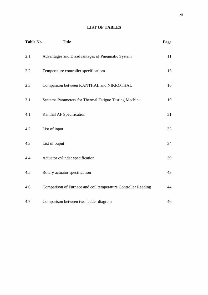
LIST OF TABLES
Table No. Title Page
2.1 Advantages and Disadvantages of Pneumatic System 11
2.2 Temperature controller specificatiom 13
2.3 Comparison between KANTHAL and NIKROTHAL 16
3.1 Systems Parameters for Thermal Fatigue Testing Machine 19
4.1 Kanthal AF Specification 31
4.2 List of input 33
4.3 List of ouput 34
4.4 Actuator cylinder specification 39
4.5 Rotary actuator specification 43
4.6 Comparison of Furnace and coil temperature Controller Reading 44
4.7 Comparison between two ladder diagram 46
xiii
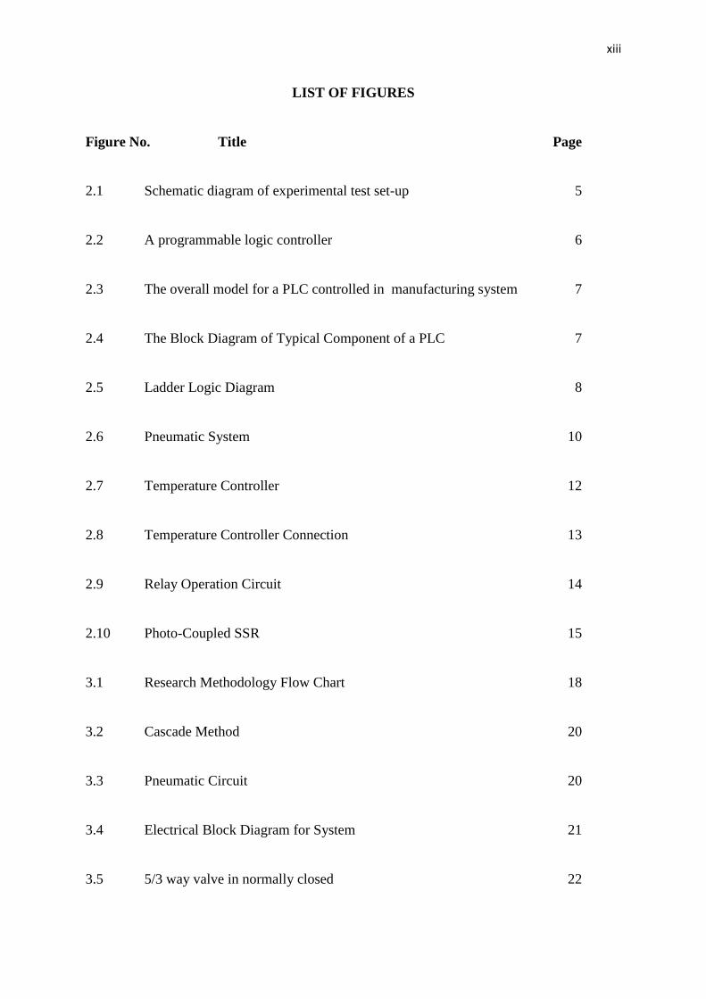
LIST OF FIGURES
Figure No. Title Page
2.1 Schematic diagram of experimental test set-up 5
2.2 A programmable logic controller 6
2.3 The overall model for a PLC controlled in manufacturing system 7
2.4 The Block Diagram of Typical Component of a PLC 7
2.5 Ladder Logic Diagram 8
2.6 Pneumatic System 10
2.7 Temperature Controller 12
2.8 Temperature Controller Connection 13
2.9 Relay Operation Circuit 14
2.10 Photo-Coupled SSR 15
3.1 Research Methodology Flow Chart 18
3.2 Cascade Method 20
3.3 Pneumatic Circuit 20
3.4 Electrical Block Diagram for System 21
3.5 5/3 way valve in normally closed 22
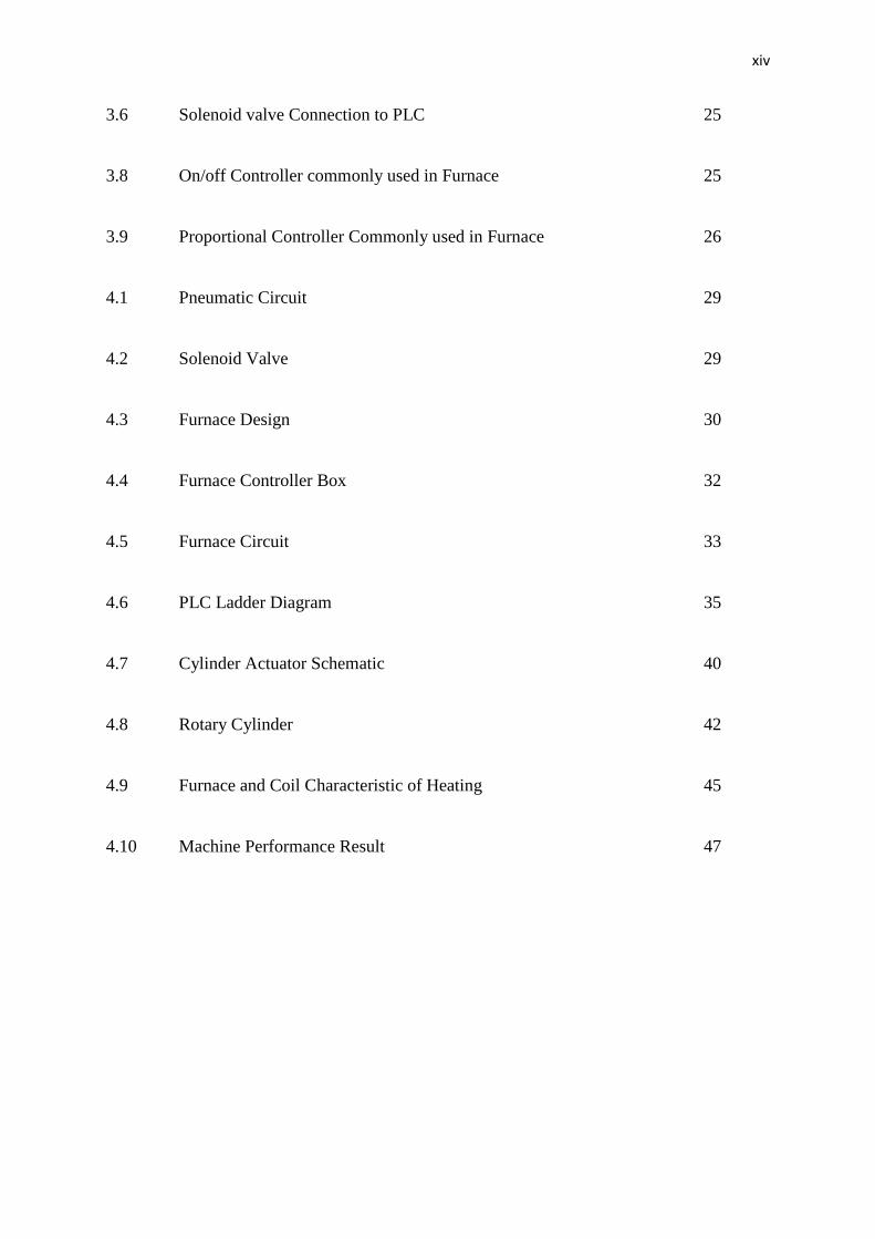
xiv
3.6 Solenoid valve Connection to PLC 25
3.8 On/off Controller commonly used in Furnace 25
3.9 Proportional Controller Commonly used in Furnace 26
4.1 Pneumatic Circuit 29
4.2 Solenoid Valve 29
4.3 Furnace Design 30
4.4 Furnace Controller Box 32
4.5 Furnace Circuit 33
4.6 PLC Ladder Diagram 35
4.7 Cylinder Actuator Schematic 40
4.8 Rotary Cylinder 42
4.9 Furnace and Coil Characteristic of Heating 45
4.10 Machine Performance Result 47
xv
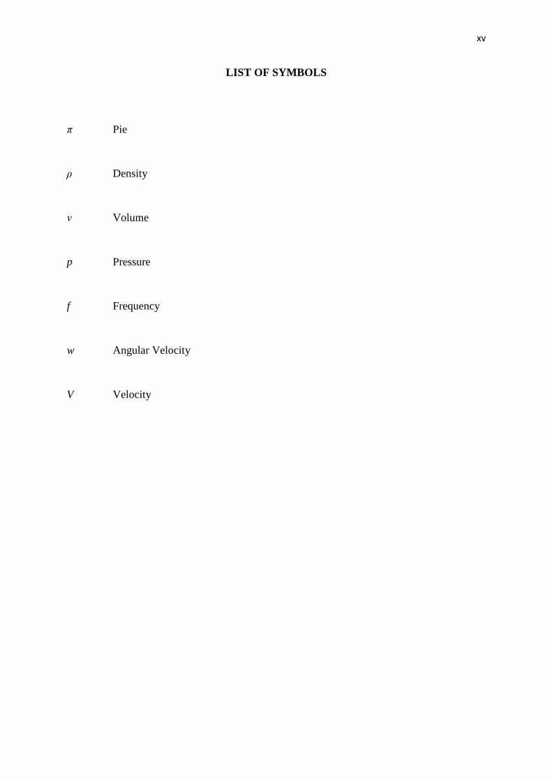
LIST OF SYMBOLS
π Pie
ρ Density
ν Volume
p Pressure
f Frequency
w Angular Velocity
V Velocity
xvi
LIST OF ABBREVIATIONS
PLC Programmable Logic Controller
SV Setting Point
Al Aluminum
PID Proportional Integral Derivative
SSR Solid State Relay
TRIAC Bidirectional Triode Thyristor
I/O Input/Output
NO Normally Open
NC Normally Closed
TM Fr
IC Internal combustion
LG Linear generator

![Front and back cover(Port) Material/officeErgonomics[1].pdf · Office ergonomic hazards are related to workstation design, job design, repetitive motion, posture, vision, thermal](https://img.pdfslide.net/doc/110x75/6003eb26bf9c18799e61aed0/front-and-back-coverport-materialofficeergonomics1pdf-office-ergonomic-hazards.jpg)