Embed Size (px)
Citation preview
Design and Evaluation of a Single-Phase Modular Multilevel Inverter
JOSE ARAQUE GALLARDO*, JORGE LUIS DIAZ **, ALDO PARDO ** Faculty of Engineering
* University of Sucre, ** University of Pamplona * Sincelejo, ** Pamplona
COLOMBIA [email protected], [email protected], [email protected]
Abstract: - This work shows the design and implementation of a cascaded single-phase modular multi-level inverter with asymmetric topology. The output of the inverter can be adjusted to 7, 15 and 31 voltage levels using a step modulation. The selective harmonic elimination (SHE) technique is used to determine the switching angles of the mosfet. The results were simulated in MATLAB and verified by the implementation of the inverter, evaluating its performance using the total harmonic distortion (THD). Keywords— Multilevel inverter, SHE, step modulation, THD, MATLAB.
1 Introduction Multilevel power inverters are a novel technology that has emerged as an alternative to traditional two-level inverters [1]. These inverters allow you to convert the electrical energy provided by direct current sources, such as batteries or solar panel banks, into an ideal alternating current of sine wave form whose parameters (amplitude, frequency) can be fixed or variable. The general concept [2] involves a high number of switches based on power semiconductors that develop the conversion at several progressive levels, achieving very low harmonic content depending on the number of levels of the inverter.
The first work related to conversion into multiple steps or voltage levels was patented in 1975 [3]. Subsequently, in 1980 a variant of multilevel inverter was patented [3], to which clamping diodes were added. The Flying Capacitor Multilevel Inverter was introduced in the mid-1990s [4], [5]. This topology offered several advantages over the NPC (Neutral Point Clamped) inverter, as is clearly stated in [6]. The cascade multilevel inverter with separate DC sources was patented in 1997 [7].
Since the first works in multi-level inverters, important advances have been made that have allowed the development and application of this technology. Among the most relevant publications can be cited [6] and [8], where a review of the state of the art of multilevel inverters is carried out. On the other hand, in [9] is presented a very interesting work that addresses the topic of the simulation of multilevel inverters. Another significant contribution has been made by master's degrees and doctoral
theses focused on multilevel inverters, within which they are cited [10-13]. Recently research has been carried out focused on the improvement of particular parameters of the multilevel inverter. For example, new topologies such as those proposed in [16] and [17], as well as the use of heuristic optimization techniques applied in the modulation of the switching signals [18] - [21].
The parameter selected to measure the performance of the inverter is the total harmonic distortion factor or THD, which is a measure of the quality of the output voltage waveform [22] - [25].
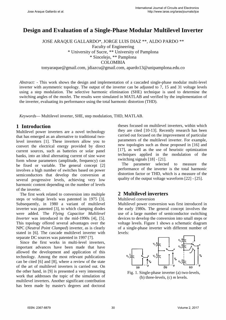
2 Multilevel inverters Multilevel conversion Multilevel power conversion was first introduced in the early 1980s. The general concept involves the use of a large number of semiconductor switching devices to develop the conversion into small steps or voltage levels. Figure 1 shows a schematic diagram of a single-phase inverter with different number of levels:
Fig. 1. Single-phase inverter (a) two-levels,
(b) three-levels, (c) m levels.
Jose Araque Gallardo et al.International Journal of Circuits and Electronics
http://www.iaras.org/iaras/journals/ijce
ISSN: 2367-8879 30 Volume 2, 2017
As can be seen in Fig. 2, in a multilevel inverter it is desired to synthesize a waveform similar to a sine signal, in which, depending on the number of available DC sources, the distortion will be much lower [26]. Among its main advantages we can mention [6]: • The multilevel input voltage arrangement allows
the input voltage to be increased several times using the same switches as a conventional inverter.
• The power of the inverters is increased by using higher voltages, without the need to increase the electrical current, thus avoiding greater losses during the current conduction, and consequently, to improve the inverter performance.
Fig. 2. Inverter output voltage (a) 2 levels,
(b) 3 levels, (c) 5 levels. Topologies There are three main topologies of multilevel
inverter: • Diode clamped inverter. • Capacitor clamped inverter. • Cascaded multilevel inverter.
Other hybrid topologies based on previous topologies have been introduced [6]: • Hybrid asymmetric multilevel inverter. • H-Bridges cascaded inverter and CD-CD
sources with insulation. • Cascaded multilevel inverter topology. • Inverter with Soft Switching. • 3 level booster rectifier / matrix inverter. • Inverter coupled by transformer.
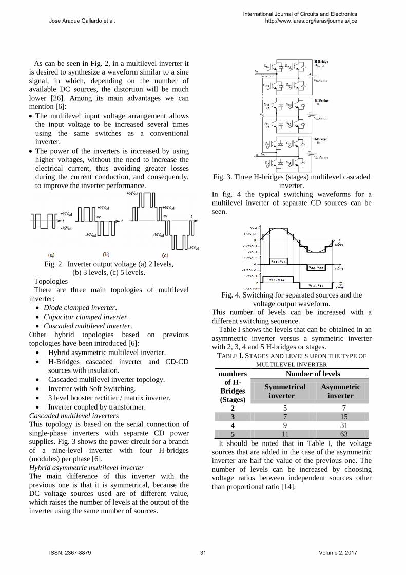
Cascaded multilevel inverters This topology is based on the serial connection of single-phase inverters with separate CD power supplies. Fig. 3 shows the power circuit for a branch of a nine-level inverter with four H-bridges (modules) per phase [6]. Hybrid asymmetric multilevel inverter The main difference of this inverter with the previous one is that it is symmetrical, because the DC voltage sources used are of different value, which raises the number of levels at the output of the inverter using the same number of sources.
Fig. 3. Three H-bridges (stages) multilevel cascaded
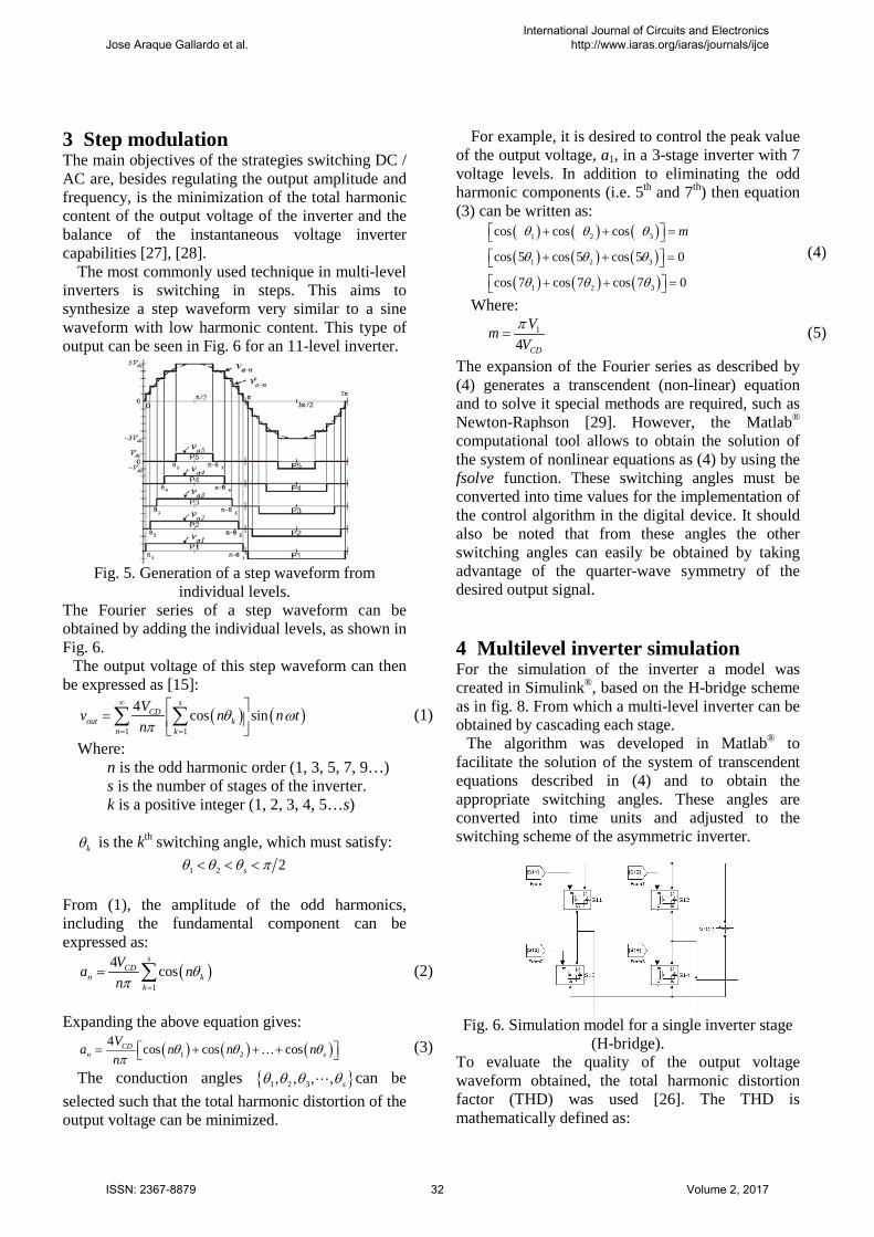
inverter. In fig. 4 the typical switching waveforms for a multilevel inverter of separate CD sources can be seen.
Fig. 4. Switching for separated sources and the
voltage output waveform. This number of levels can be increased with a different switching sequence.
Table I shows the levels that can be obtained in an asymmetric inverter versus a symmetric inverter with 2, 3, 4 and 5 H-bridges or stages.
TABLE I. STAGES AND LEVELS UPON THE TYPE OF MULTILEVEL INVERTER
numbers of H-
Bridges (Stages)
Number of levels
Symmetrical inverter
Asymmetric inverter
2 5 7 3 7 15 4 9 31 5 11 63
It should be noted that in Table I, the voltage sources that are added in the case of the asymmetric inverter are half the value of the previous one. The number of levels can be increased by choosing voltage ratios between independent sources other than proportional ratio [14].
Jose Araque Gallardo et al.International Journal of Circuits and Electronics
http://www.iaras.org/iaras/journals/ijce
ISSN: 2367-8879 31 Volume 2, 2017
3 Step modulation The main objectives of the strategies switching DC / AC are, besides regulating the output amplitude and frequency, is the minimization of the total harmonic content of the output voltage of the inverter and the balance of the instantaneous voltage inverter capabilities [27], [28].
The most commonly used technique in multi-level inverters is switching in steps. This aims to synthesize a step waveform very similar to a sine waveform with low harmonic content. This type of output can be seen in Fig. 6 for an 11-level inverter.
Fig. 5. Generation of a step waveform from
individual levels. The Fourier series of a step waveform can be obtained by adding the individual levels, as shown in Fig. 6.
The output voltage of this step waveform can then be expressed as [15]:
( ) ( )1 1
4 cos sins
CDout k
n k
Vv n n tn
θ ωπ
∞
= =
=
∑ ∑ (1)
Where: n is the odd harmonic order (1, 3, 5, 7, 9…) s is the number of stages of the inverter. k is a positive integer (1, 2, 3, 4, 5…s)
kθ is the kth switching angle, which must satisfy:
1 2 2sθ θ θ π< < <
From (1), the amplitude of the odd harmonics, including the fundamental component can be expressed as:
( )1
4 coss
CDn k
k
Va nn
θπ =
= ∑ (2)
Expanding the above equation gives:
( ) ( ) ( )1 24 cos cos cosCD
n sVa n n nn
θ θ θπ
= + + +
(3)
The conduction angles { }1 2 3, , , , sθ θ θ θ can be selected such that the total harmonic distortion of the output voltage can be minimized.
For example, it is desired to control the peak value of the output voltage, a1, in a 3-stage inverter with 7 voltage levels. In addition to eliminating the odd harmonic components (i.e. 5th and 7th) then equation (3) can be written as:
( ) ( ) ( )( ) ( ) ( )( ) ( ) ( )
1 2 3
1 2 3
1 2 3
cos cos cos
cos 5 cos 5 cos 5 0
cos 7 cos 7 cos 7 0
mθ θ θ
θ θ θ
θ θ θ
+ + = + + = + + =
(4)
Where: 1
4 CD
VmVπ
= (5)
The expansion of the Fourier series as described by (4) generates a transcendent (non-linear) equation and to solve it special methods are required, such as Newton-Raphson [29]. However, the Matlab® computational tool allows to obtain the solution of the system of nonlinear equations as (4) by using the fsolve function. These switching angles must be converted into time values for the implementation of the control algorithm in the digital device. It should also be noted that from these angles the other switching angles can easily be obtained by taking advantage of the quarter-wave symmetry of the desired output signal.
4 Multilevel inverter simulation For the simulation of the inverter a model was created in Simulink®, based on the H-bridge scheme as in fig. 8. From which a multi-level inverter can be obtained by cascading each stage.
The algorithm was developed in Matlab® to facilitate the solution of the system of transcendent equations described in (4) and to obtain the appropriate switching angles. These angles are converted into time units and adjusted to the switching scheme of the asymmetric inverter.
Fig. 6. Simulation model for a single inverter stage
(H-bridge). To evaluate the quality of the output voltage waveform obtained, the total harmonic distortion factor (THD) was used [26]. The THD is mathematically defined as:
Jose Araque Gallardo et al.International Journal of Circuits and Electronics
http://www.iaras.org/iaras/journals/ijce
ISSN: 2367-8879 32 Volume 2, 2017
( ) ( )2
31
1% 100%nn
THD aa
∞
=
= ⋅∑ (6)
Where: a1 is the amplitude of the fundamental harmonic. an is the amplitude of the nth odd harmonic.
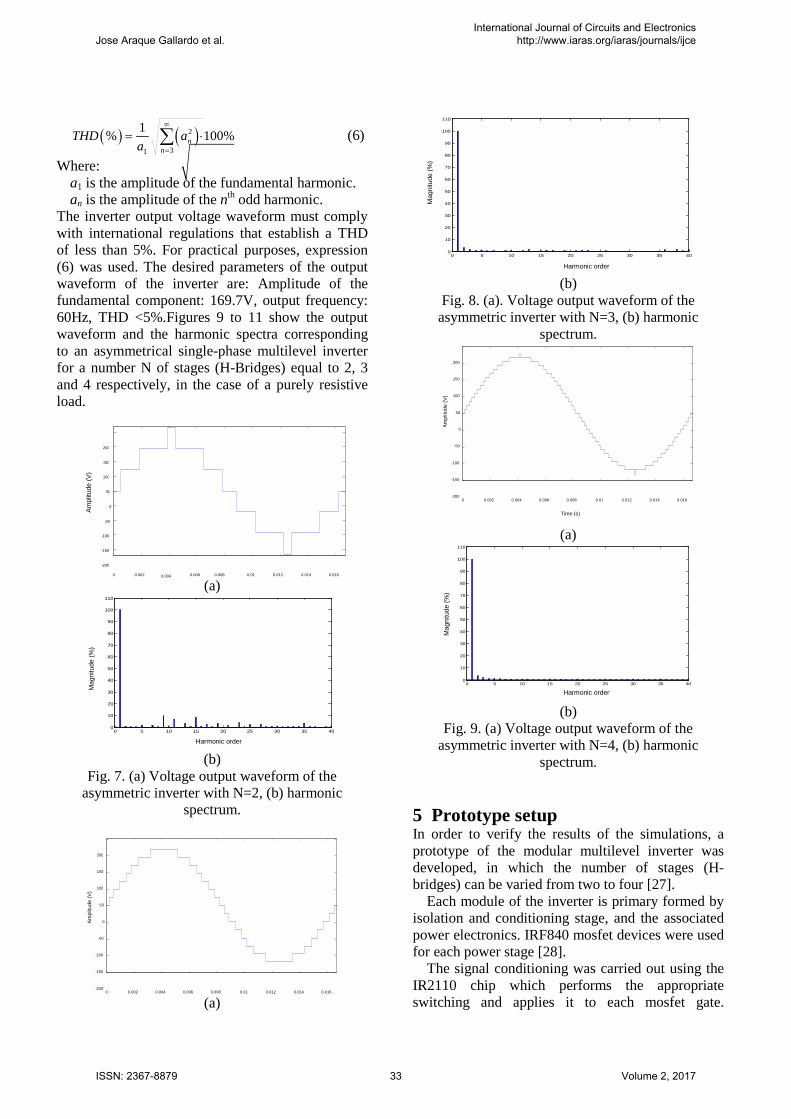
The inverter output voltage waveform must comply with international regulations that establish a THD of less than 5%. For practical purposes, expression (6) was used. The desired parameters of the output waveform of the inverter are: Amplitude of the fundamental component: 169.7V, output frequency: 60Hz, THD <5%.Figures 9 to 11 show the output waveform and the harmonic spectra corresponding to an asymmetrical single-phase multilevel inverter for a number N of stages (H-Bridges) equal to 2, 3 and 4 respectively, in the case of a purely resistive load.
(a)
0 5 10 15 20 25 30 35 400
10
20
30
40
50
60
70
80
90
100
110
Mag
nitud
(%)
(b) Fig. 7. (a) Voltage output waveform of the
asymmetric inverter with N=2, (b) harmonic spectrum.
(a)
0 5 10 15 20 25 30 35 400
10
20
30
40
50
60
70
80
90
100
110
(b) Fig. 8. (a). Voltage output waveform of the
asymmetric inverter with N=3, (b) harmonic spectrum.
(a)
0 5 10 15 20 25 30 35 400
10
20
30
40
50
60
70
80
90
100
110
Mag
nitud
(%)
(b) Fig. 9. (a) Voltage output waveform of the
asymmetric inverter with N=4, (b) harmonic spectrum.
5 Prototype setup In order to verify the results of the simulations, a prototype of the modular multilevel inverter was developed, in which the number of stages (H-bridges) can be varied from two to four [27].
Each module of the inverter is primary formed by isolation and conditioning stage, and the associated power electronics. IRF840 mosfet devices were used for each power stage [28].
The signal conditioning was carried out using the IR2110 chip which performs the appropriate switching and applies it to each mosfet gate.
0 0.002 0.006 0.01 0.012 0.014 0.016 -200 -150 -100
-50 0
50 100 150 200
0.008
0 0.002 0.004 0.006 0.008 0.01 0.012 0.014 0.016 -200 -150 -100
-50 0
50 100 150 200
0 0.002 0.004 0.006 0.008 0.01 0.012 0.014 0.016 -200 -150 -100
-50 0
50 100 150 200
Harmonic order
Mag
nitu
de (%
)
Harmonic order
Harmonic order
Mag
nitu
de (%
)
Mag
nitu
de (%
)
Am
plitu
de (V
)
0.004
Am
plitu
de (V
)
Am
plitu
de (V
)
Time (s)
Jose Araque Gallardo et al.International Journal of Circuits and Electronics
http://www.iaras.org/iaras/journals/ijce
ISSN: 2367-8879 33 Volume 2, 2017
Isolation was performed with 4N25 optocouplers. The generation of the switching sequence was performed using a PIC18F4550. Experimental setup
In order to evaluate the performance of the multilevel inverter, experimental tests with purely resistive load were carried out. The output waveforms were measured with an Agilent DSO3202A type oscilloscope. The data were then taken to a Personal Computer where the THD value and the harmonics spectrum were calculated. Fig. 12 shows a block diagram of the experimental setup.
Fig. 10. Experimental setup.
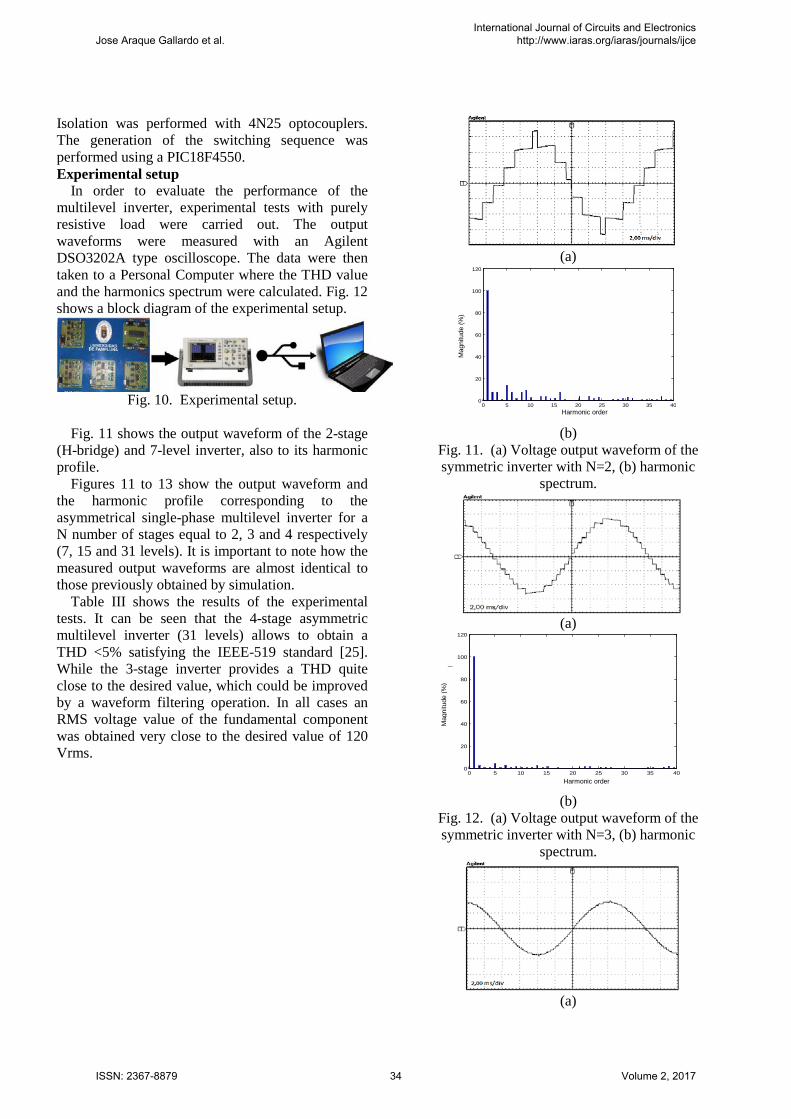
Fig. 11 shows the output waveform of the 2-stage
(H-bridge) and 7-level inverter, also to its harmonic profile.
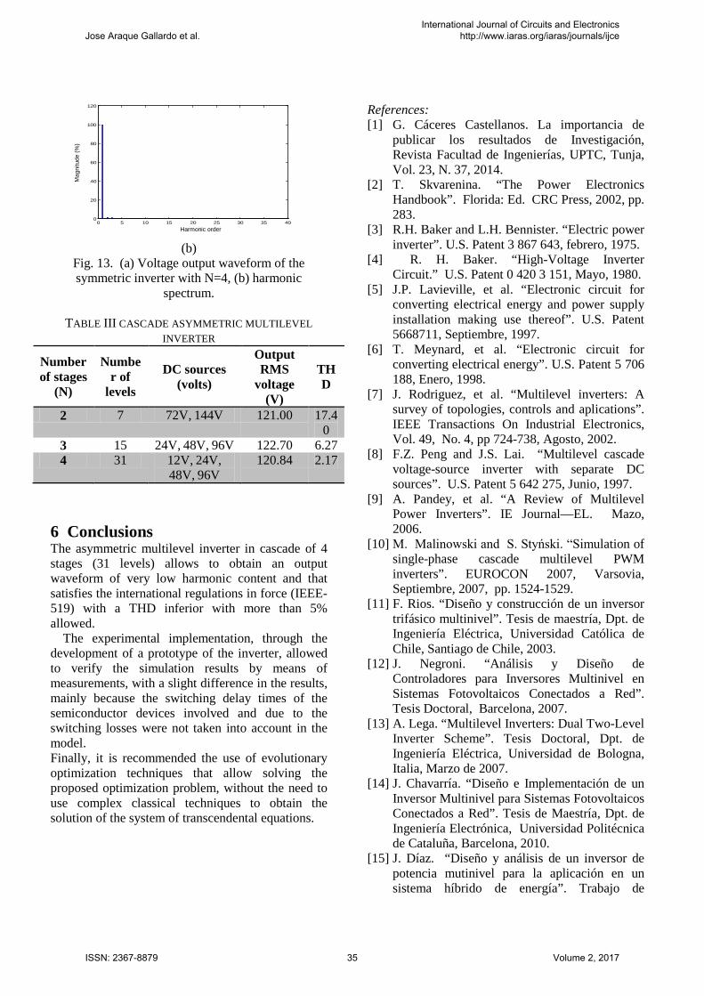
Figures 11 to 13 show the output waveform and the harmonic profile corresponding to the asymmetrical single-phase multilevel inverter for a N number of stages equal to 2, 3 and 4 respectively (7, 15 and 31 levels). It is important to note how the measured output waveforms are almost identical to those previously obtained by simulation.
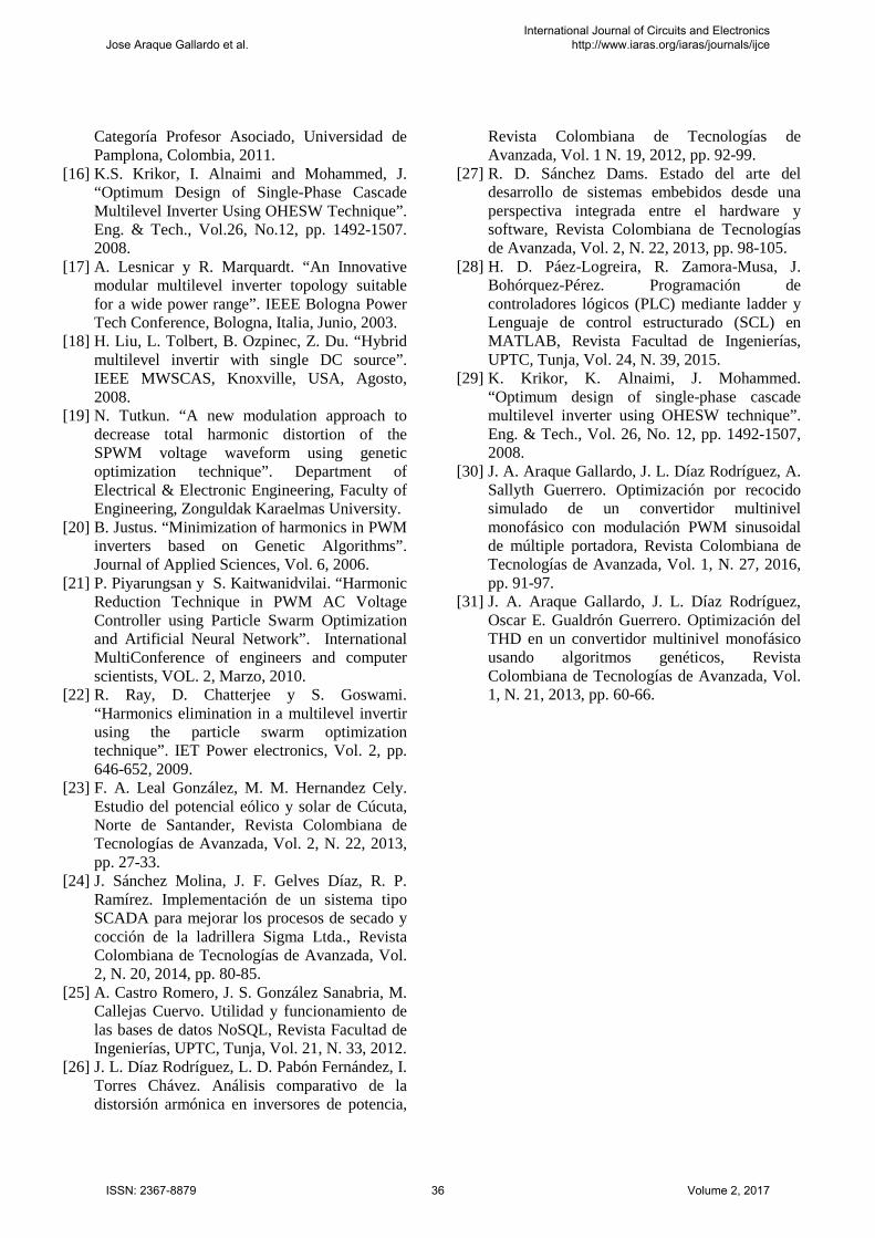
Table III shows the results of the experimental tests. It can be seen that the 4-stage asymmetric multilevel inverter (31 levels) allows to obtain a THD <5% satisfying the IEEE-519 standard [25]. While the 3-stage inverter provides a THD quite close to the desired value, which could be improved by a waveform filtering operation. In all cases an RMS voltage value of the fundamental component was obtained very close to the desired value of 120 Vrms.
(a)
0 5 10 15 20 25 30 35 400
20
40
60
80
100
120
Mag
nitu
d (%
de
la fu
ndam
enta
l)
(b) Fig. 11. (a) Voltage output waveform of the symmetric inverter with N=2, (b) harmonic
spectrum.
(a)
0 5 10 15 20 25 30 35 400
20
40
60
80
100
120
Mag
nitud
(% d
e la
fund
amen
tal)
(b) Fig. 12. (a) Voltage output waveform of the symmetric inverter with N=3, (b) harmonic
spectrum.
(a)
Harmonic order
Mag
nitu
de (%
)
Harmonic order
Mag
nitu
de (%
)
Jose Araque Gallardo et al.International Journal of Circuits and Electronics
http://www.iaras.org/iaras/journals/ijce
ISSN: 2367-8879 34 Volume 2, 2017
0 5 10 15 20 25 30 35 400
20
40
60
80
100
120
Magn
itud (
% de
la fu
ndam
ental
)
(b) Fig. 13. (a) Voltage output waveform of the symmetric inverter with N=4, (b) harmonic
spectrum.
TABLE III CASCADE ASYMMETRIC MULTILEVEL INVERTER
Number of stages
(N)
Number of
levels
DC sources (volts)
Output RMS
voltage (V)
THD
2 7 72V, 144V 121.00 17.40
3 15 24V, 48V, 96V 122.70 6.27 4 31 12V, 24V,
48V, 96V 120.84 2.17
6 Conclusions The asymmetric multilevel inverter in cascade of 4 stages (31 levels) allows to obtain an output waveform of very low harmonic content and that satisfies the international regulations in force (IEEE-519) with a THD inferior with more than 5% allowed.
The experimental implementation, through the development of a prototype of the inverter, allowed to verify the simulation results by means of measurements, with a slight difference in the results, mainly because the switching delay times of the semiconductor devices involved and due to the switching losses were not taken into account in the model. Finally, it is recommended the use of evolutionary optimization techniques that allow solving the proposed optimization problem, without the need to use complex classical techniques to obtain the solution of the system of transcendental equations.
References: [1] G. Cáceres Castellanos. La importancia de
publicar los resultados de Investigación, Revista Facultad de Ingenierías, UPTC, Tunja, Vol. 23, N. 37, 2014.
[2] T. Skvarenina. “The Power Electronics Handbook”. Florida: Ed. CRC Press, 2002, pp. 283.
[3] R.H. Baker and L.H. Bennister. “Electric power inverter”. U.S. Patent 3 867 643, febrero, 1975.
[4] R. H. Baker. “High-Voltage Inverter Circuit.” U.S. Patent 0 420 3 151, Mayo, 1980.
[5] J.P. Lavieville, et al. “Electronic circuit for converting electrical energy and power supply installation making use thereof”. U.S. Patent 5668711, Septiembre, 1997.
[6] T. Meynard, et al. “Electronic circuit for converting electrical energy”. U.S. Patent 5 706 188, Enero, 1998.
[7] J. Rodriguez, et al. “Multilevel inverters: A survey of topologies, controls and aplications”. IEEE Transactions On Industrial Electronics, Vol. 49, No. 4, pp 724-738, Agosto, 2002.
[8] F.Z. Peng and J.S. Lai. “Multilevel cascade voltage-source inverter with separate DC sources”. U.S. Patent 5 642 275, Junio, 1997.
[9] A. Pandey, et al. “A Review of Multilevel Power Inverters”. IE Journal—EL. Mazo, 2006.
[10] M. Malinowski and S. Styński. “Simulation of single-phase cascade multilevel PWM inverters”. EUROCON 2007, Varsovia, Septiembre, 2007, pp. 1524-1529.
[11] F. Rios. “Diseño y construcción de un inversor trifásico multinivel”. Tesis de maestría, Dpt. de Ingeniería Eléctrica, Universidad Católica de Chile, Santiago de Chile, 2003.
[12] J. Negroni. “Análisis y Diseño de Controladores para Inversores Multinivel en Sistemas Fotovoltaicos Conectados a Red”. Tesis Doctoral, Barcelona, 2007.
[13] A. Lega. “Multilevel Inverters: Dual Two-Level Inverter Scheme”. Tesis Doctoral, Dpt. de Ingeniería Eléctrica, Universidad de Bologna, Italia, Marzo de 2007.
[14] J. Chavarría. “Diseño e Implementación de un Inversor Multinivel para Sistemas Fotovoltaicos Conectados a Red”. Tesis de Maestría, Dpt. de Ingeniería Electrónica, Universidad Politécnica de Cataluña, Barcelona, 2010.
[15] J. Díaz. “Diseño y análisis de un inversor de potencia mutinivel para la aplicación en un sistema híbrido de energía”. Trabajo de
Harmonic order
Mag
nitu
de (%
)
Jose Araque Gallardo et al.International Journal of Circuits and Electronics
http://www.iaras.org/iaras/journals/ijce
ISSN: 2367-8879 35 Volume 2, 2017
Categoría Profesor Asociado, Universidad de Pamplona, Colombia, 2011.
[16] K.S. Krikor, I. Alnaimi and Mohammed, J. “Optimum Design of Single-Phase Cascade Multilevel Inverter Using OHESW Technique”. Eng. & Tech., Vol.26, No.12, pp. 1492-1507. 2008.
[17] A. Lesnicar y R. Marquardt. “An Innovative modular multilevel inverter topology suitable for a wide power range”. IEEE Bologna Power Tech Conference, Bologna, Italia, Junio, 2003.
[18] H. Liu, L. Tolbert, B. Ozpinec, Z. Du. “Hybrid multilevel invertir with single DC source”. IEEE MWSCAS, Knoxville, USA, Agosto, 2008.
[19] N. Tutkun. “A new modulation approach to decrease total harmonic distortion of the SPWM voltage waveform using genetic optimization technique”. Department of Electrical & Electronic Engineering, Faculty of Engineering, Zonguldak Karaelmas University.
[20] B. Justus. “Minimization of harmonics in PWM inverters based on Genetic Algorithms”. Journal of Applied Sciences, Vol. 6, 2006.
[21] P. Piyarungsan y S. Kaitwanidvilai. “Harmonic Reduction Technique in PWM AC Voltage Controller using Particle Swarm Optimization and Artificial Neural Network”. International MultiConference of engineers and computer scientists, VOL. 2, Marzo, 2010.
[22] R. Ray, D. Chatterjee y S. Goswami. “Harmonics elimination in a multilevel invertir using the particle swarm optimization technique”. IET Power electronics, Vol. 2, pp. 646-652, 2009.
[23] F. A. Leal González, M. M. Hernandez Cely. Estudio del potencial eólico y solar de Cúcuta, Norte de Santander, Revista Colombiana de Tecnologías de Avanzada, Vol. 2, N. 22, 2013, pp. 27-33.
[24] J. Sánchez Molina, J. F. Gelves Díaz, R. P. Ramírez. Implementación de un sistema tipo SCADA para mejorar los procesos de secado y cocción de la ladrillera Sigma Ltda., Revista Colombiana de Tecnologías de Avanzada, Vol. 2, N. 20, 2014, pp. 80-85.
[25] A. Castro Romero, J. S. González Sanabria, M. Callejas Cuervo. Utilidad y funcionamiento de las bases de datos NoSQL, Revista Facultad de Ingenierías, UPTC, Tunja, Vol. 21, N. 33, 2012.
[26] J. L. Díaz Rodríguez, L. D. Pabón Fernández, I. Torres Chávez. Análisis comparativo de la distorsión armónica en inversores de potencia,
Revista Colombiana de Tecnologías de Avanzada, Vol. 1 N. 19, 2012, pp. 92-99.
[27] R. D. Sánchez Dams. Estado del arte del desarrollo de sistemas embebidos desde una perspectiva integrada entre el hardware y software, Revista Colombiana de Tecnologías de Avanzada, Vol. 2, N. 22, 2013, pp. 98-105.
[28] H. D. Páez-Logreira, R. Zamora-Musa, J. Bohórquez-Pérez. Programación de controladores lógicos (PLC) mediante ladder y Lenguaje de control estructurado (SCL) en MATLAB, Revista Facultad de Ingenierías, UPTC, Tunja, Vol. 24, N. 39, 2015.
[29] K. Krikor, K. Alnaimi, J. Mohammed. “Optimum design of single-phase cascade multilevel inverter using OHESW technique”. Eng. & Tech., Vol. 26, No. 12, pp. 1492-1507, 2008.
[30] J. A. Araque Gallardo, J. L. Díaz Rodríguez, A. Sallyth Guerrero. Optimización por recocido simulado de un convertidor multinivel monofásico con modulación PWM sinusoidal de múltiple portadora, Revista Colombiana de Tecnologías de Avanzada, Vol. 1, N. 27, 2016, pp. 91-97.
[31] J. A. Araque Gallardo, J. L. Díaz Rodríguez, Oscar E. Gualdrón Guerrero. Optimización del THD en un convertidor multinivel monofásico usando algoritmos genéticos, Revista Colombiana de Tecnologías de Avanzada, Vol. 1, N. 21, 2013, pp. 60-66.
Jose Araque Gallardo et al.International Journal of Circuits and Electronics
http://www.iaras.org/iaras/journals/ijce
ISSN: 2367-8879 36 Volume 2, 2017