Embed Size (px)
Citation preview

Design And Flow Through CFD Analysis Of
Enclosed Impeller
Ashish J. Patel1, Bhaumik B. Patel2
1 M.E (Machine Design) Student, Mechanical Engineering,
Kalol Institute of Technology and Research Centre, Kalol, Gujarat, India
2
Assistant Professor, Mechanical Engineering Department,
Kalol Institute of Technology and Research
Centre, Kalol, Gujarat, India,
Gujarat Technological University
Abstract -- The Impeller of Centrifugal Pump is one of most
Critical Component to be designed. The Flow through
Centrifugal Pump impeller is three dimensional and fully
turbulence model. The present work describes the design and
flow through CFD analysis of enclosed impeller of the
centrifugal Pump. The model of impeller was generated using
SOLIDWORKS and analyzed in ANSYS (Workbench) Fluid
Flow (CFX). The numerical solution of the discredited three
dimensional, incompressible Navier-Stokes equations over an
unstructured grid is accomplished with an ANSYS-CFX. The
design of enclosed impeller is done by using various input
data, the value of head is determined by theoretical as well as
CFD value. The CFD analysis of Enclosed impeller has been
carried out at various inlet and outlet blade angles of the
impeller and number of blades of impeller to investigate the
changes in head as well as efficiencies.
Keywords – Impeller Design, Solid Works, CFD, Pressure
Distribution, Efficiency
1. INTRODUCTION
A pump is a machinery or device for raising, compressing
or transferring fluid. A fluid can be gasses or any liquid.
Pumps are one of the most often sold and used mechanical
devices and can be found in almost every industry. Pumps
alone do not create pressure; they only displace fluid,
causing a flow. Adding resistance to flow causes pressure.
Pumps fall into five major groups: direct lift, velocity,
buoyancy and gravity pumps.
A centrifugal pump is a kinetic device. Liquid entering the
pump receives kinetic energy from the rotating impeller.
The centrifugal action of the impeller accelerates the liquid
to a high velocity, transferring mechanical (rotational)
energy to the liquid. That kinetic energy is available to the
fluid to accomplish work. The centrifugal pumps act as a
reversed of an inward radial flow reaction turbine.
Centrifugal pumps consist of a set of rotating vanes,
enclosed within a housing or casing, used to impart energy
to a fluid through centrifugal force.
2. OBJECTIVE
To Perform Design and Flow through CFD analysis of the
Enclosed impeller in Ansys software with modification in
inlet and outlet blade angles of the impeller and number of
blades of the impeller to investigate the changes in head as
well as efficiencies.
3. LITERATURE REVIEW
E.C. Bcharoudis et. al. [1] have contributed to reveal the
flow mechanisms inside centrifugal impellers and studied
performance by varying outlet blade angle. They observed
a gain in head more than 7 % with increase in outlet blade
angle from 20 degree to 45 degree.
K. M. Pandey et. al. [2] have performed two-dimensional
steady numerical analysis for centrifugal pumps with
impeller blades 7, 8 and 9 using Ansys Fluent 6.3 software
for inlet diameter 80 mm and outlet diameter 168 mm at
2500 rpm rotational speed also to investigate the changes in
head as well as efficiencies with the increase of blade
number.
S.Rajendran et. al. [3] have performed the simulation of the
flow in the impeller of a centrifugal pump. The flow
pattern, pressure distribution in the blade passage, blade
loading and pressure plots are discussed.
4. Design of Enclosed Impeller
For
design calculation, the design Parameters of
CROMPTON SRAM-400 Pump are taken as follows:
Table 4.1 Design Data for Pump
Sr.
No
Parameters
Value
1
Flow rate
0.5 m3/s
2
Head
30 m
3
Pump Speed
735 rpm
4
Gravitational Acceleration
9.81 m/s2
5
Density of Sewage Water
1050 kg/m3
International Journal of Engineering Research & Technology (IJERT)
IJERT
IJERT
ISSN: 2278-0181
www.ijert.org
Vol. 3 Issue 7, July - 2014
IJERTV3IS071198
(This work is licensed under a Creative Commons Attribution 4.0 International License.)
1366
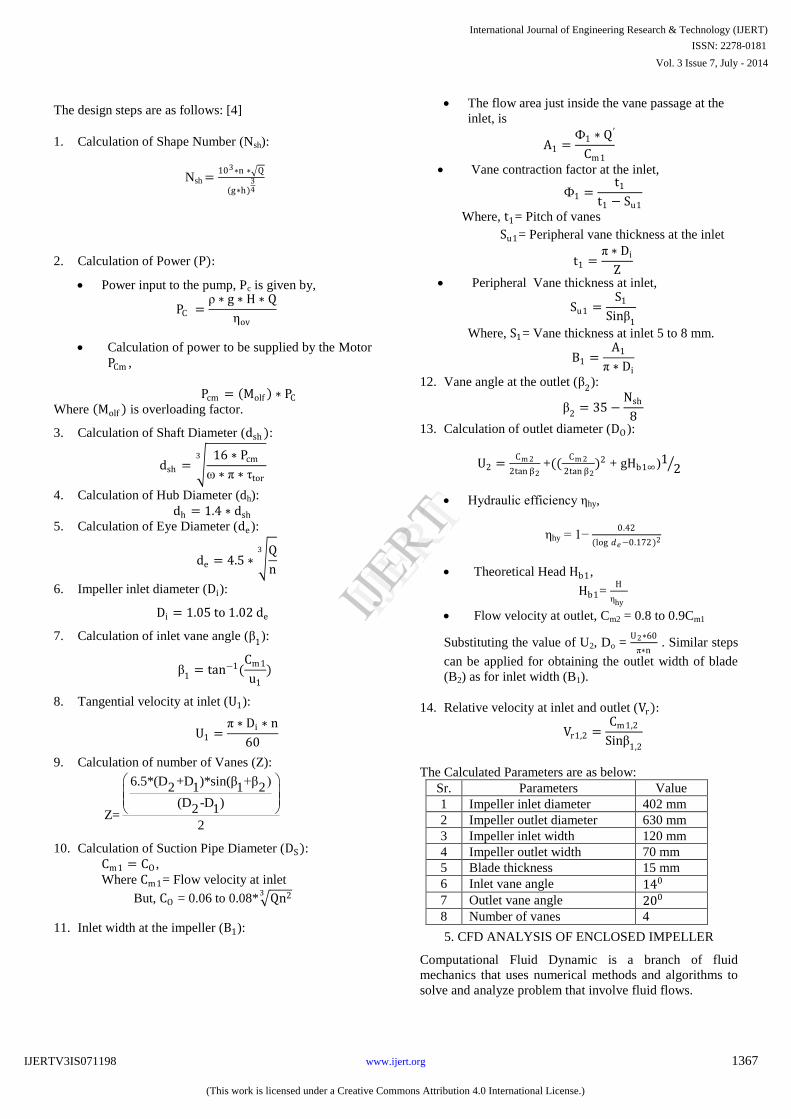
The design steps are as follows: [4]
1.
Calculation of Shape Number (Nsh):
Nsh =103∗n
∗ Q
(g∗h)34
2.
Calculation of Power (P):
Power input to the pump, Pc
is given by,
PC
=ρ ∗ g ∗ H ∗ Q
ηov
Calculation of power to be supplied by the Motor
PCm ,
Pcm = Molf ∗ PC
Where Molf
is overloading factor.
3.
Calculation of Shaft Diameter (dsh ):
dsh = 16 ∗ Pcm
ω ∗ π ∗ τtor
3
4.
Calculation of Hub Diameter (dh):
dh = 1.4 ∗ dsh
5.
Calculation of Eye Diameter (de):
de = 4.5 ∗ Q
n
3
6.
Impeller
inlet diameter (Di):
Di = 1.05
to
1.02
de
7.
Calculation of inlet vane angle (β1):
β1
= tan−1(Cm1
u1
)
8.
Tangential velocity at inlet (U1):
U1 =π ∗ Di ∗ n
60
9.
Calculation of number of Vanes (Z):
6.5*(D +D )*sin(β +β )2 1 1 2
(D -D )2 1Z=
2
10.
Calculation of Suction Pipe Diameter (DS ):
Cm1 = CO ,
Where Cm1= Flow velocity at inlet
But, CO
= 0.06 to 0.08* Qn23
11.
Inlet width at the impeller (B1):
The flow area just inside the vane passage at the
inlet, is
A1 =Ф1 ∗ Q′
Cm1
Vane contraction factor at the inlet,
Ф1 =t1
t1 − Su1
Where, t1= Pitch of vanes
Su1= Peripheral vane thickness at the inlet
t1 =π ∗ Di
Z
Peripheral Vane thickness at inlet,
Su1 =S1
Sinβ1
Where, S1= Vane thickness at inlet 5 to 8 mm.
B1 =A1
π ∗ Di
12. Vane angle at the outlet (β2):
β2
= 35 −Nsh
8
13. Calculation of outlet diameter (DO):
U2 =Cm 2
2tan β2 +((
Cm 2
2tan β2)2 + gHb1∞)1 2
Hydraulic efficiency ηhy,
ηhy = 1− 0.42
(log 𝑑𝑒−0.172)2
Theoretical Head Hb1,
Hb1= H
ηhy
Flow velocity at outlet, Cm2 = 0.8 to 0.9Cm1
Substituting the value of U2, Do = U2∗60
π∗n . Similar steps
can be applied for obtaining the outlet width of blade
(B2) as for inlet width (B1).
14. Relative velocity at inlet and outlet (Vr):
Vr1,2 =Cm1,2
Sinβ1,2
The Calculated Parameters are as below:
Sr. Parameters Value
1 Impeller inlet diameter 402 mm
2 Impeller outlet diameter 630 mm
3 Impeller inlet width 120 mm
4 Impeller outlet width 70 mm
5 Blade thickness 15 mm
6 Inlet vane angle 140
7 Outlet vane angle 200
8 Number of vanes 4
5. CFD ANALYSIS OF ENCLOSED IMPELLER
Computational Fluid Dynamic is a branch of fluid
mechanics that uses numerical methods and algorithms to
solve and analyze problem that involve fluid flows.
International Journal of Engineering Research & Technology (IJERT)
IJERT
IJERT
ISSN: 2278-0181
www.ijert.org
Vol. 3 Issue 7, July - 2014
IJERTV3IS071198
(This work is licensed under a Creative Commons Attribution 4.0 International License.)
1367

Figure 5.1 CFD methodology
6. BOUNDARY CONDITIONS
Centrifugal pump impeller domain is considered as rotating
frame of reference with a rotational speed of 735 rpm. The
working fluid through the pump is water at 27 0C. k-ε
turbulence model with turbulence intensity of 5% is
considered. Inlet and outlet Pressure and mass flow rate of
0.5 m3/s are given as boundary conditions. Three
dimensional incompressible N-S equations are solved with
Ansys-CFX Solver.
7. PROCEDURE OF CFD ANALYSIS
Step1. 3D Model of Impeller is generated in
SOLIDWORKS 2009 as per above given Drawing.
Figure 7.1 3D Model of Impeller
Step2. Our CFD Analysis method is Cavity Patten so we
have to create Cavity model of above impeller.
Step3. Save above Cavity model in *. IGES Format for
Importing into ANSYS Workbench Mesh Module for
Meshing.
Figure 7.2 Cavity Model of Impeller
Step4. Import above Cavity model in ANSYS Workbench
Mesh Module.
Figure 7.3 Cavity model of impeller in ANSYS Workbench
Step5. Meshing of Impeller
Meshing Type: 3D
Type of Element: Tetrahedral
International Journal of Engineering Research & Technology (IJERT)
IJERT
IJERT
ISSN: 2278-0181
www.ijert.org
Vol. 3 Issue 7, July - 2014
IJERTV3IS071198
(This work is licensed under a Creative Commons Attribution 4.0 International License.)
1368

No. of Nodes: 46403
No. of Elements: 241146
Figure7.4 Meshed Model of Impeller Cavity
Step6. Save above model in *.CMDB Format for importing
into ANSYS CFX Pre.
Step7. Import above .CMDB File in ANSYS CFX Pre.
Figure 7.5 Impeller Cavity in ANSYS CFX Pre
Step8. Define Water + Particle Domain.
Domain Type: Fluid
Domain Fluid: Water + 5 mm Particle
Domain motion: Rotating
Domain RPM: 735 rpm
Rotating about: Y Axis
Figure 7.6 Water + Particle Domain
Step9. Define Heat Transfer and Turbulence model.
Figure 7.7 Heat Transfer and Turbulence Model
Heat Transfer Model: Total Energy
Turbulence Model: k- epsilon
Where k is the turbulence kinetic energy and is defined as
the variance of the fluctuations in velocity. It has
dimensions of (L2 T-2); for example, m2/s2.
ε is the turbulence eddy dissipation (the rate at which the
velocity fluctuations dissipate), as well as dimensions of k
per unit time (L2 T-3) (e.g., m2/s3).
The k-ε model introduces two new variables into the
system of equations. The continuity equation is then:
∂ρ
∂t+ ∇ • ρU = 0
and the momentum equation becomes
∂ρU
∂t+ ∇ • ρU ⨂U − ∇ • μef f ∇U
= ∇P′ + ∇ • μef f
∇U T + B
Step10. Define Hub as a Rotating Wall
Wall Roughness: Smooth Wall
Heat Transfer: Adiabatic
Figure 7.8 Hub as a Rotating Wall
Step11. Define Shroud as a Rotating Wall.
International Journal of Engineering Research & Technology (IJERT)
IJERT
IJERT
ISSN: 2278-0181
www.ijert.org
Vol. 3 Issue 7, July - 2014
IJERTV3IS071198
(This work is licensed under a Creative Commons Attribution 4.0 International License.)
1369

Figure 7.9 Shroud as a Rotating Wall
Step12. Define inlet for Impeller
Define inlet mass Flow Rate: 0.5 m3/s
Static Frame to Total Temperature: 300 K
Figure 7.10 Inlet for Impeller
Step13. Define Outlet for Impeller
Define Outlet mass Flow Rate: 0.5 m3/s
Figure 7.11 Outlet for Impeller
Step14. Define Solver Control Criteria.
Figure 7.12 Solver Control Criteria
Number of Outer loop iteration: 100
Convergence Criteria:
Residual Target: 1e-4
Step15. Run the Analysis
7.2 Results of Analysis:
Inlet Angle: 140
Outlet Angle: 200
Figure 7.13 Velocity Contour
Figure 7.13 shows minimum velocity is 1.035*101 m/s and
maximum velocity is 4.051*101 m/s.
International Journal of Engineering Research & Technology (IJERT)
IJERT
IJERT
ISSN: 2278-0181
www.ijert.org
Vol. 3 Issue 7, July - 2014
IJERTV3IS071198
(This work is licensed under a Creative Commons Attribution 4.0 International License.)
1370

Figure 7.14 Inlet Pressure Contour
Figure shows pressure contours at inlet, it helps one in
identifying the maximum and minimum pressure at the
inlet when the fluid comes in contact with the blade. Here
minimum inlet pressure is 1.625*105 Pascal and maximum
inlet pressure is 1.752*105 Pascal.
Figure 7.15 Outlet Pressure Contour
Figure shows that pressure at outlet of impeller, before
entering the casing. Here minimum outlet pressure is
4.825*105 Pascal and maximum outlet pressure is
4.925*105 Pascal.
Head = Outlet Pressure −Inlet Pressure
ρ ∗ g
= 4.925e5 −1.752e5
1050 ∗ 9.81
Head = 30.804 m
7.3 Modification in Inlet and Outlet Blade Angles of
Impeller
Here we took various inlet and outlet blade angles to show
pressure distribution at inlet and outlet of impeller before
entering the casing. Among them the best result was taken
and discussed below.
Inlet Angle: 140
Outlet Angle: 180
Figure 7.16 Outlet Pressure Contour
Here minimum outlet pressure is 5.401*105 Pascal and
maximum outlet pressure is 5.426*105Pascal. Figure 4.29
shows inlet pressure contour at inlet blade angle 140 and
outlet blade angle 180 at which fluid leave the impeller and
pump get maximum efficiency (approximately 96%).
Figure 7.17 Inlet Pressure Contour
Here minimum inlet pressure is 1.613*105 Pascal and
maximum inlet pressure is 1.690*105Pascal. Figure 4.30
shows inlet pressure contour at inlet blade angle 140 and
outlet blade angle 180 which indicate maximum pressure at
which fluid comes in contact with the impeller and the
head is maximum(approximately 36 m).
Head = Outlet Pressure −Inlet Pressure
ρ ∗ g
= (5.426 e5 - 1.69 e5)/(1050 * 9.81)
= 36.27 m
Table 7.1 Generated Head at Various
Blade Angles Sr.
No Inlet Angle
Outlet
Angle
Head
(m)
ƞ
(%)
1 160 220 33.52 90.86
2 160 200 34.59 93.76
3 160 180 35.27 95.60
4 140 220 28.34 76.82
5 140 200 30.80 81.00
6 140 180 36.27 96.68
7 120 220 26.15 70.88
8 120 200 28.96 78.50
9 120 180 36.12 95.94
International Journal of Engineering Research & Technology (IJERT)
IJERT
IJERT
ISSN: 2278-0181
www.ijert.org
Vol. 3 Issue 7, July - 2014
IJERTV3IS071198
(This work is licensed under a Creative Commons Attribution 4.0 International License.)
1371

Figure7.18 Generated Head Vs. Efficiency
7.4 Modification in Number of Blades of
Impeller
Figure 7.19 Outet Pressure Contour at Number of Blades 3
Figure 7.20 Inlet Pressure Contour at Number of Blades 3
Figure 7.21 Inlet Pressure Contour at Number of Blades 4
Figure 7.22 Outlet pressure Contour at Number of Blades 4
Figure 7.23 Outlet pressure Contour at Number of Blades 5
0
20
40
60
80
100
Eff
icie
ncy
Generated Head
International Journal of Engineering Research & Technology (IJERT)
IJERT
IJERT
ISSN: 2278-0181
www.ijert.org
Vol. 3 Issue 7, July - 2014
IJERTV3IS071198
(This work is licensed under a Creative Commons Attribution 4.0 International License.)
1372

Figure 7.24 Inlet pressure Contour at Number of Blades 5
Figure7.25 Number of Blades Vs. Head
CONCLUSION
The CFD predicted value of the head
at the designed flow
rate is approximately H=30.804 m. There is 8.04% of
difference between the theoretical head and the predicted
numerical head.
From the CFD analysis of centrifugal pump impeller, the
maximum generated head is 36.27m
at inlet blade angle
140
and outlet blade angle 180
respectively and the pump
efficiency is approximately 96%.
With modification in number of blades of impeller, it is
conclude that head is decreases at number of blades 3 and
5. So number of 4 blade impeller is suitable for this pump.
REFERENCES [1] E. C. Bacharoudis, A. E. Filios, M. D. Mentzos and D. P. Margaris,
“Parametric Study of a Centrifugal Pump Impeller by Varying the
Outlet Blade Angle”, The open Mechanical Engineering Journal,
2008, 2, 75-83. [2] K. M. Pandey, A. P. Singh and Sujoy Chakraborty, “Numerical
studies in effect of Blade number variations on performance of
Centrifugal Pumps at 2500 rpm”, Journal of Environmental Research and Development, Vol.6 No. 3A, Jan-March 2012.
[3] S.Rajendran and Dr.k.Purushothaman, “Analysis of a centrifugal
pump impeller using ANSYS-CFX”, International Journal of Engineering Research & Technology (IJERT) Vol. 1 Issue 3, May –
2012, ISSN: 2278-0181.
[4] Prof. S. Kumaraswamy. “Databook for design of Centrifugal Pumps”. Center for Industrial Consultancy and Sponsored Research,
IIT Madras.
[5] Sujoy Chakraborty, Kishan Chaudhary, Prasenjit Dutta, “Performance prediction of Centrifugal pumps with variations of
blade number”, Journal of science and Industrial research, vol.72,
June 2013, pp. 373-378. [6] Weidong zhou, Zhimei Zhao, T. S. Lee, and S. H. Winoto,
“Investigation of flow through Centrifugal Pump Impellers using
Computational Fluid Dynamics”, International Journal of Rotating Machinery, 9(1): 49-61, 2003.
[7] C. P. Kothandaraman, R. Rudramoorthy, “Fluid Mechanics And Machinery (Second Edition)”, Handbook, New Age International (P)
Limited, Publishers.
[8]G.K. Sahu., Pumps, New Age International Publishers, First edition, 2000.
[9] John D. Anderson Jr., Joris Degroote, G´erard Degrez, Erik Dick,
“Computational Fluid Dynamics an Introduction”, Handbook, Springer.
International Journal of Engineering Research & Technology (IJERT)
IJERT
IJERT
ISSN: 2278-0181
www.ijert.org
Vol. 3 Issue 7, July - 2014
IJERTV3IS071198
(This work is licensed under a Creative Commons Attribution 4.0 International License.)
1373