Embed Size (px)
Citation preview

1
Design and Implementation of a Single-frequency
Mesh Network using OpenAirInterfaceFlorian Kaltenberger, Rizwan Ghaffar, Raymond Knopp, Hicham Anouar, Christian Bonnet
Eurecom
2229, Route des Cretes - B.P. 193
06904 Sophia Antipolis, France
Email (corresponding author): [email protected]
Abstract—OpenAirInterface is an experimental open-sourcereal-time hardware and software platform for experimentationin wireless communications and signal processing. With the helpof OpenAirInterface researchers can demonstrate novel ideasquickly and verify them in a realistic environment.
Its current implementation provides a full open-source soft-ware modem comprising physical and link layer functionalitiesfor cellular and mesh network topologies. The physical (PHY)layer of the platform targets fourth generation wireless networksand thus uses orthogonal frequency division multiple access(OFDMA) together with multiple-input multiple-output (MIMO)techniques. The current hardware supports 5 MHz bandwidthand two transmit/receive antennas. The media access (MAC)layer of the platform supports an abundant two-way signalingfor enabling collaboration, scheduling protocols as well as trafficand channel measurements.
In this paper we focus on the mesh topology and show howto implement a single-frequency mesh network with OpenAir-Interface. The key ingredients to enable such a network are adual-stream MIMO receiver structure and a distributed networksynchronization algorithm. We show how to implement thesetwo algorithms in real-time on the OpenAirInterface platform.Further we provide results from field trials and compare themto the simulation results.
I. INTRODUCTION
The design and implementation of next generation wireless
networks is a very challenging task. To ensure optimal perfor-
mance it is necessary to carry out performance evaluations
and field trials in parallel to standard development. Easily
reconfigurable testbeds are a convenient way to investigate new
ideas and to tackle many problems at an early development
stage.
Novel ideas for wireless networks are usually first studied
using computer simulations based on some kind of model
of the network, the hardware and the radio channel. These
models usually make assumptions in order to simplify or
isolate the problem at hand. However, it might turn out that the
assumptions are not fulfilled in a real environment. An easily
Eurecom’s Research is supported in part by its industrial partners: Swiss-com, Thales, SFR, Orange France, ST Ericsson, SAP, Cisco, BMW Group,Monaco Telecom, Symantec. This work is also funded in part by theEuropean Commission through project CHORIST (ICT/FP6), the FrenchNational Research Agency (ANR) through projects AIRNET and HNPS, andby the Wiener Wissenschafts-, Forschungs-und Technologiefonds (WWTF)through the project PUCCO. Parts of this work were presented at theCOST2100 Workshop on MIMO and Cooperative Communications, June2008, Trondheim, Norway.
reconfigurable experimental platform allows to study novel
algorithms under realistic conditions. Comparing simulation
results with results from lab tests and field trials reveals if
initial assumptions were correct or if they need to be refined.
This paper presents the Eurecom testbed OpenAirInterface,
which is an experimental real-time, open-source hardware
and software platform for future wireless networks. Ope-
nAirInterface can be seen as a mock standard for realistic
experimentation purposes which retains the salient features of
a real radio system, without all the required mechanisms one
would find in a standard used in deployment of commercial
networks. Its aim is to study techniques such as multi-cell co-
operative techniques, distributed synchronization, interference
coordination and cancellation.
OpenAirInterface features an open-source software modem
written in C comprising physical and link layer functionali-
ties for cellular and mesh network topologies. This software
modem can be used either for extensive computer simulations
using different channel models or it can be used for real-time
operation. In the latter case, it is run under the control of the
real-time application interface (RTAI) which is an extension
of the Linux operating system.
The use of an open-source software modem has several
advantages. Firstly, the same code can be initially debugged
and tuned in simulation before using it in the real-time modem
(where debugging and performance analysis is much harder).
Secondly, the system is very flexible and parameters like frame
structure, pilot placement, etc., can be changed rather easily.
Thirdly, researchers can implement new ideas rather fast,
without having to use very sophisticated hardware description
languages (HDL). Last but not least since all code is open-
source, other researchers can use easily adjust the modem to
their needs and collaboration is fostered.
Other highlights of the OpenAirInterface platform are its
usage as measurement platform or as an emulation platform
which allow to study different aspects of a wireless network
in isolation. In the emulation mode, the physical layer is
abstracted and emulated over the ethernet. This approach
allows to test and investigate MAC and link-level algorithms
without using the radio interface [1]. The OpenAirInterface
can also be used to perform channel measurements which can
be used for channel characterization and capacity analysis [2].
Apart from a general overview of OpenAirInterface, in this
paper we present OpenAirMesh—a specification of wireless
2
mesh network and its implementation on the OpenAirInterface
platform. OpenAirMesh exemplifies two major challenges in
future wireless networks. The first challenge is interference
which is caused by a very tight frequency reuse in order
to increase the network throughput. Interference is especially
strong for users at the cell edge severely limiting user’s
throughput. We propose a low-complexity dual-stream MIMO
receiver that is able to cancel out interference from a neigh-
boring cell and show its implementation and performance on
the OpenAirInterface. This example also highlights the insight
that OpenAirInterface provides for developing multi-cell al-
gorithms. More concretely it was found out that frequency
offsets and receive correlation have a very strong influence on
the receiver performance and can thus not be neglected in the
simulations.
Another big challenge in future wireless networks is syn-
chronization between nodes, especially indoors where a refer-
ence timing signal such as the one provided by the global
positioning system (GPS) cannot be used. Synchronization
is needed for example for the dual-stream MIMO receiver
and to enable the collaboration between base-stations both on
the media access (MAC) and the physical (PHY) layer. The
distributed synchronization algorithm proposed in this paper
can be interpreted as a form of firefly synchronization [3].
Related Work: Many people have recognized the advan-
tages of testbeds for wireless networks. However, many of
them focus on a particular layer, such as the physical layer,
the link layer or the network layer. A good overview of
testbeds that focus on the physical layer and especially MIMO
communications is given in [4, 5].
Most of the testbeds that provide both physical and link
layer functionalities (like OpenAirInterface) are either based
on the Universal Software Radio Peripheral (USRP) from
Ettus Research [6] together with the GNU software radio
[7] or the wireless open-access research platform (WARP)
from Rice University [8]. For example, the Hydra testbed of
the University of Texas in Austin [9] is based on the GNU
radio platform while the WAPRnet testbed [10] is based on
WARP platform. The WiTestLab from the Polytechnic Institute
of NYU [11] has been experimenting with both platforms.
Another testbed example it the Cognitive Radio Testbed from
Berkley [12], which uses the Berkeley Emulation Engine 2
(BEE2) [13] as an implementation platform.
Compared to the OpenAirInterface platform, the GNU radio
project does not provide a full reference design, but only
building blocks. Further, a MAC layer implementation is
missing in the current distribution. Also the USRP hardware
has its limitations, mainly due to the connection to the PC over
USB or Ethernet, which severely limits the achievable system
throughput. Like the OpenAirInterface, WARP is also a full
software defined radio (SDR), but physical layer algorithms
have to be developed either directly in VHDL or using the
Xilinx System Generator toolchain for Matlab. Compared to
the use of C language in OpenAirInterface, the use of VHDL
is more cumbersome and time consuming. Also, the Xilinx
System Generator is not openly available. The BEE2 platform
is a very flexible hardware platform, which has been designed
for a multitude of applications. However, no software modem
exists for this platform.
Last but not least we mention here the two testbeds devel-
oped within the EASY-C project1 that were set up in Berlin
[14] and in Dresden [15] (both Germany). The project is
a cooperation between German universities, research centers
and industry and focuses on LTE-Advanced technologies.
However, both testbeds use proprietary hardware and software
and are not openly accessible.
Organization: Section II gives an overview of the Ope-
nAirInterface experimental platform. Section III presents the
network, the link layer and the physical layer architecture
of OpenAirMesh—a mesh network built using the OpenAir-
Interface. Section IV describes the two building blocks for
the implementation of OpenAirMesh: a novel low-complexity
dual-stream receiver architecture and the distributed synchro-
nization algorithm. Finally we show results from computer
simulations as well as real experiments in Section V. We
conclude the paper in Section VI.
Notation: Let C denote the set of complex numbers.
Scalars are denoted by x. Column vectors and matrices are
denoted by a and A and their elements are denoted by ai
and Ai,j respectively. Transpose and Hermitian transpose are
denoted by ·T and ·H . IM is the identity matrix of size M and
0M is an M -dimensional vector of zeros. The Euclidean (ℓ2)
norm of a vector a is denoted by ‖a‖ and the Frobenius norm
of a matrix A is denoted by ‖A‖F . E denotes expectation,
and CN (m,C) denotes a multivariate proper complex normal
distribution with mean vector m and covariance matrix C.
II. OPENAIRINTERFACE OVERVIEW
The OpenAirInterface platform consists of both hardware
and the software components. Additionally it comprises dif-
ferent simulation tools as well as collaborative web tools.
The hardware components are described in subsection II-A.
In subsection II-B we describe the basic organization of the
OpenAirInterface software components (which are available
under the GNU GPL from the OpenAirInterface website2).
A. Hardware Components
In OpenAirInterface there are two different hardware mod-
ules available: CardBus MIMO 1 (CBMIMO1) and it suc-
cessor Express MIMO. All current activities (including the
experiments described in this paper) are based on CBMIMO1.
In the following we will describe the main characteristics of
the two boards.
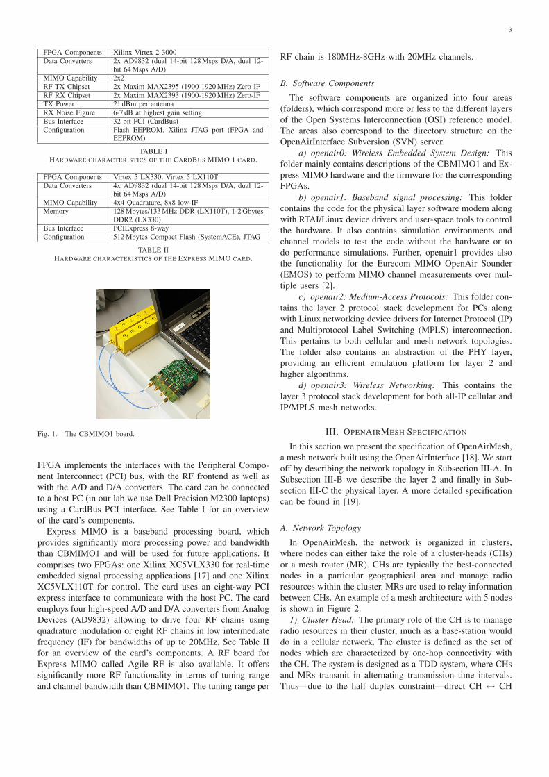
The CBMIMO1 board (cf. Figure 1) comprises two time-
division duplex (TDD) radio frequency (RF) chains operating
at 1.900-1.920 GHz with 5 MHz channels and 21dBM transmit
power per antenna for an orthogonal frequency division mod-
ulated (OFDM) waveform3. The cards house a medium-scale
field programmable gate array (FPGA) (Xilinx X2CV3000)
which makes use of the open-source LEON3 embedded pro-
cessor from Gaisler research [16]. In the current version, the
1http://www.easy-c.de2http://www.openairinterface.org3EURECOM has a frequency allocation for experimentation around its
premises in Sophia Antipolis.
3
FPGA Components Xilinx Virtex 2 3000
Data Converters 2x AD9832 (dual 14-bit 128 Msps D/A, dual 12-bit 64 Msps A/D)
MIMO Capability 2x2
RF TX Chipset 2x Maxim MAX2395 (1900-1920 MHz) Zero-IF
RF RX Chipset 2x Maxim MAX2393 (1900-1920 MHz) Zero-IF
TX Power 21 dBm per antenna
RX Noise Figure 6-7 dB at highest gain setting
Bus Interface 32-bit PCI (CardBus)
Configuration Flash EEPROM, Xilinx JTAG port (FPGA andEEPROM)
TABLE IHARDWARE CHARACTERISTICS OF THE CARDBUS MIMO 1 CARD.
FPGA Components Virtex 5 LX330, Virtex 5 LX110T
Data Converters 4x AD9832 (dual 14-bit 128 Msps D/A, dual 12-bit 64 Msps A/D)
MIMO Capability 4x4 Quadrature, 8x8 low-IF
Memory 128 Mbytes/133 MHz DDR (LX110T), 1-2 GbytesDDR2 (LX330)
Bus Interface PCIExpress 8-way
Configuration 512 Mbytes Compact Flash (SystemACE), JTAG
TABLE IIHARDWARE CHARACTERISTICS OF THE EXPRESS MIMO CARD.
Fig. 1. The CBMIMO1 board.
FPGA implements the interfaces with the Peripheral Compo-
nent Interconnect (PCI) bus, with the RF frontend as well as
with the A/D and D/A converters. The card can be connected
to a host PC (in our lab we use Dell Precision M2300 laptops)
using a CardBus PCI interface. See Table I for an overview
of the card’s components.
Express MIMO is a baseband processing board, which
provides significantly more processing power and bandwidth
than CBMIMO1 and will be used for future applications. It
comprises two FPGAs: one Xilinx XC5VLX330 for real-time
embedded signal processing applications [17] and one Xilinx
XC5VLX110T for control. The card uses an eight-way PCI
express interface to communicate with the host PC. The card
employs four high-speed A/D and D/A converters from Analog
Devices (AD9832) allowing to drive four RF chains using
quadrature modulation or eight RF chains in low intermediate
frequency (IF) for bandwidths of up to 20MHz. See Table II
for an overview of the card’s components. A RF board for
Express MIMO called Agile RF is also available. It offers
significantly more RF functionality in terms of tuning range
and channel bandwidth than CBMIMO1. The tuning range per
RF chain is 180MHz-8GHz with 20MHz channels.
B. Software Components
The software components are organized into four areas
(folders), which correspond more or less to the different layers
of the Open Systems Interconnection (OSI) reference model.
The areas also correspond to the directory structure on the
OpenAirInterface Subversion (SVN) server.
a) openair0: Wireless Embedded System Design: This
folder mainly contains descriptions of the CBMIMO1 and Ex-
press MIMO hardware and the firmware for the corresponding
FPGAs.
b) openair1: Baseband signal processing: This folder
contains the code for the physical layer software modem along
with RTAI/Linux device drivers and user-space tools to control
the hardware. It also contains simulation environments and
channel models to test the code without the hardware or to
do performance simulations. Further, openair1 provides also
the functionality for the Eurecom MIMO OpenAir Sounder
(EMOS) to perform MIMO channel measurements over mul-
tiple users [2].
c) openair2: Medium-Access Protocols: This folder con-
tains the layer 2 protocol stack development for PCs along
with Linux networking device drivers for Internet Protocol (IP)
and Multiprotocol Label Switching (MPLS) interconnection.
This pertains to both cellular and mesh network topologies.
The folder also contains an abstraction of the PHY layer,
providing an efficient emulation platform for layer 2 and
higher algorithms.
d) openair3: Wireless Networking: This contains the
layer 3 protocol stack development for both all-IP cellular and
IP/MPLS mesh networks.
III. OPENAIRMESH SPECIFICATION
In this section we present the specification of OpenAirMesh,
a mesh network built using the OpenAirInterface [18]. We start
off by describing the network topology in Subsection III-A. In
Subsection III-B we describe the layer 2 and finally in Sub-
section III-C the physical layer. A more detailed specification
can be found in [19].
A. Network Topology
In OpenAirMesh, the network is organized in clusters,
where nodes can either take the role of a cluster-heads (CHs)
or a mesh router (MR). CHs are typically the best-connected
nodes in a particular geographical area and manage radio
resources within the cluster. MRs are used to relay information
between CHs. An example of a mesh architecture with 5 nodes
is shown in Figure 2.
1) Cluster Head: The primary role of the CH is to manage
radio resources in their cluster, much as a base-station would
do in a cellular network. The cluster is defined as the set of
nodes which are characterized by one-hop connectivity with
the CH. The system is designed as a TDD system, where CHs
and MRs transmit in alternating transmission time intervals.
Thus—due to the half duplex constraint—direct CH ↔ CH
4
CH1 CH2
MR2MR1 MR3
Cluster 1 Cluster 2
Fig. 2. The mesh network topology is organized in clusters. Each clusteris controlled by a cluster head (CH). Other nodes in the network are calledmesh routers (MR) since they can be used to relay information between CHs.
communication is not supported. The downlink (CH → MR)
signaling channels allow for the CH to schedule transmission
of labels (in the form of time and frequency mappings on
the radio resource) each of which carry different types of
traffic throughout the mesh network according to pre-defined
quality-of-service (QoS) descriptors. The Uplink (UL) signal-
ing channels (MR → CH) are used for relaying bandwidth
requirement indicators and channel quality measurements from
nodes within the cluster. These feed the scheduling algorithms
residing in the CH and allow for proper resource allocation
satisfying QoS negotiations carried out using Layer 3 (L3)
signaling. The latter are beyond the scope of the description
in this paper.
2) Mesh Router: The primary role of an MR is to interpret
the scheduling information from the CH on the downlink (DL)
signaling channels in order to route the traffic corresponding
to the scheduled labels on the allocated physical resources.
MRs can also be connected to more than one cluster at the
same time. Since all CHs transmit on the same time-frequency
ressources, MRs must be able to cancel interference. See
Section IV-A for details.
B. Layer 2 Protocol Stack
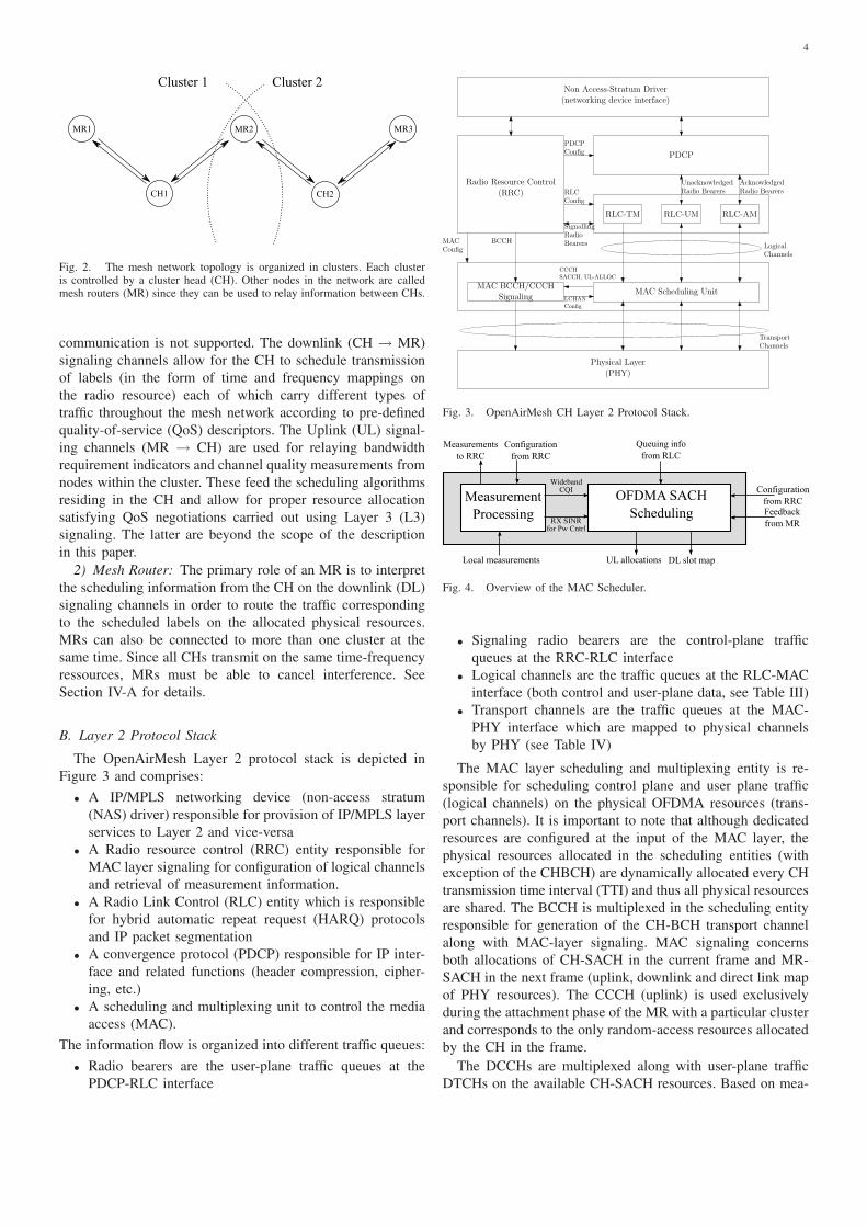
The OpenAirMesh Layer 2 protocol stack is depicted in
Figure 3 and comprises:
• A IP/MPLS networking device (non-access stratum
(NAS) driver) responsible for provision of IP/MPLS layer
services to Layer 2 and vice-versa
• A Radio resource control (RRC) entity responsible for
MAC layer signaling for configuration of logical channels
and retrieval of measurement information.
• A Radio Link Control (RLC) entity which is responsible
for hybrid automatic repeat request (HARQ) protocols
and IP packet segmentation
• A convergence protocol (PDCP) responsible for IP inter-
face and related functions (header compression, cipher-
ing, etc.)
• A scheduling and multiplexing unit to control the media
access (MAC).
The information flow is organized into different traffic queues:
• Radio bearers are the user-plane traffic queues at the
PDCP-RLC interface
MAC Scheduling Unit
Radio Resource Control(RRC)
RLC-AMRLC-TM RLC-UM
MAC BCCH/CCCHSignaling
Physical Layer(PHY)
PDCPConfig
RLCConfig
MACConfig
UnacknowledgedRadio Bearers
AcknowledgedRadio Bearers
BCCHLogicalChannels
SignallingRadioBearers
PDCP
CCCH
SACCH, UL-ALLOC
LCHAN
Config
Non Access-Stratum Driver(networking device interface)
TransportChannels
Fig. 3. OpenAirMesh CH Layer 2 Protocol Stack.
Measurement
Processing
OFDMA SACH
Scheduling
WidebandCQI
RX SINRfor Pw Cntrl
Measurements
to RRC
Configuration
from RRC
Queuing info
from RLC
Configuration
from RRCFeedback
from MR
DL slot mapUL allocationsLocal measurements
Fig. 4. Overview of the MAC Scheduler.
• Signaling radio bearers are the control-plane traffic
queues at the RRC-RLC interface
• Logical channels are the traffic queues at the RLC-MAC
interface (both control and user-plane data, see Table III)
• Transport channels are the traffic queues at the MAC-
PHY interface which are mapped to physical channels
by PHY (see Table IV)
The MAC layer scheduling and multiplexing entity is re-
sponsible for scheduling control plane and user plane traffic
(logical channels) on the physical OFDMA resources (trans-
port channels). It is important to note that although dedicated
resources are configured at the input of the MAC layer, the
physical resources allocated in the scheduling entities (with
exception of the CHBCH) are dynamically allocated every CH
transmission time interval (TTI) and thus all physical resources
are shared. The BCCH is multiplexed in the scheduling entity
responsible for generation of the CH-BCH transport channel
along with MAC-layer signaling. MAC signaling concerns
both allocations of CH-SACH in the current frame and MR-
SACH in the next frame (uplink, downlink and direct link map
of PHY resources). The CCCH (uplink) is used exclusively
during the attachment phase of the MR with a particular cluster
and corresponds to the only random-access resources allocated
by the CH in the frame.
The DCCHs are multiplexed along with user-plane traffic
DTCHs on the available CH-SACH resources. Based on mea-
5
Broadcast Control Channel BCCH Low bit-rate control channel used by a CH for broadcasting basic information to nodes in the cluster.
Common Control Channel CCCH Low bit-rate control channel used both during the attachment or association phase of a new node.
Dedicated Control Channel DCCH Access-layer signaling information (RLC return channels, RF measurement reporting, traffic measurementreporting, power control, etc.) to the corresponding node.
Dedicated Traffic Channel DTCH Variable bit-rate traffic channel with negotiated QoS parameters used by the mesh network to transport datatraffic corresponding to a particular flow.
TABLE IIILOGICAL CHANNELS.
CH Broadcast Channel CH-BCH Broadcast control channel which houses MAC-layer signaling for CH and MR physical resourcescheduling as well as layer 2 radio-resource control (RRC) signaling for topology and QoS management.
CH Scheduled-Access Channel CH-SACH Data channel (for both control and user-plane logical channels) used by CH to communicate with a nodein its cluster.
MR Broadcast Channel MR-BCH Broadcast resource used by MR to extend the coverage of a cluster during topological discovery.
MR Scheduled-Access Channel MR-SACH Data channel (for both control and user-plane logical channels) used by MR to communicate with a CH.
Random-Access Channel RACH Signaling channel used by a MR during the association phase with the CH.
TABLE IVTRANSPORT AND PHYSICAL CHANNELS. EACH OF THE TRANSPORT CHANNELS IS MAPPED TO A CORRESPONDING PHYSICAL CHANNEL OF THE SAME
NAME.
Physical CH Synchronization Channel CHSCH Pilot resource reserved to a CH which is responsible for delivering synchronization information tonodes in the cluster.
Physical Synchronization Channel MRSCH Pilot resource used by a MR to allow the CH to estimate the channel of an MR.
TABLE VADDITIONAL PHYSICAL CHANNELS.
Symbol (DFT/IDFT) size 256 samplesPrefix length 64 samples
Useful carriers 160Number of subbands (chunks) 16
Data carriers per subband 8Pilots per subband 2
OFDM symbols/frame 64
TABLE VIOFDMA PARAMETERS IN OPENAIRMESH.
surement and feedback information, SACH scheduling (see
Figure 4) aims to respect the negotiated QoS of each logical
channel, while maximizing the aggregate spectral efficiency
of the data streams. Different wideband scheduling policies
taking into account both queuing measures from RLC and
channel quality feedback can be accommodated (see for in-
stance [20]). Channel quality information is signaled between
corresponding MAC-layers based quantized wideband channel
estimates received from PHY.
C. Physical Layer
The physical layer of the platform uses orthogonal fre-
quency division multiple access (OFDMA) together with
multiple-input multiple-output (MIMO) techniques and is sim-
ilar to that of fourth generation wireless networks such as
WiMAX or LTE. The parameters for OpenAirMesh are given
in Table VI.
The MIMO-OFDMA system provides the means for trans-
mitting several multiple-bitrate streams (multiplexed over sub-
carriers and antennas) in parallel. Moreover, PHY signaling
strategies are included to provide the means for exploiting
channel state feedback at the transmitters in order to allow for
advanced PHY allocation of OFDMA resources via the MAC.
In addition to the physical channels of Table IV, there are
two synchronization channels (see Table V) which are used
for parameter estimation. In the following we describe the
Guard (2 symbols)SCH0 (for RACH)RACHSCH1 (for cluster 0)SCH2 (for cluster 1)SCH3 (for MRBCH)MRBCH
CHSCH0 (common synch)CHSCH1 (for cluster 0)CHSCH2 (for cluster 1)CHSCH3 (for cluster 2)CHBCH (8 symbols)
unusedunusedGuard (2 symbols)
SACH frequency group - minimumsize 160 bits (Rate 1/2, QPSK-SISO)
20 symbols10 carriers/symb (8 data, 2 pilot)
20 symbols10 carriers/symb (8 data, 2 pilot)
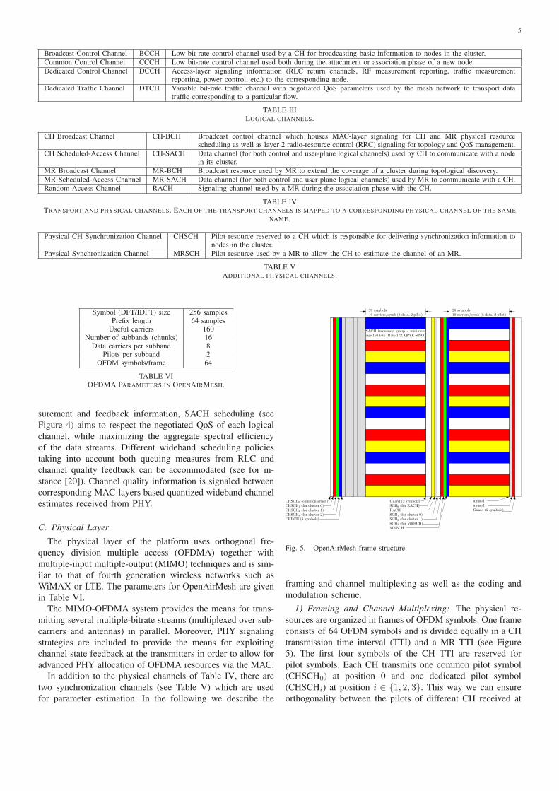
Fig. 5. OpenAirMesh frame structure.
framing and channel multiplexing as well as the coding and
modulation scheme.
1) Framing and Channel Multiplexing: The physical re-
sources are organized in frames of OFDM symbols. One frame
consists of 64 OFDM symbols and is divided equally in a CH
transmission time interval (TTI) and a MR TTI (see Figure
5). The first four symbols of the CH TTI are reserved for
pilot symbols. Each CH transmits one common pilot symbol
(CHSCH0) at position 0 and one dedicated pilot symbol
(CHSCHi) at position i ∈ {1, 2, 3}. This way we can ensure
orthogonality between the pilots of different CH received at
6
one MR. The pilot symbols are followed by the broadcast
channel (CH-BCH), which contains 128 data subcarriers and
32 pilot subcarriers. The remaining 20 OFDM symbols of the
CH TTI frame are divided into 16 ressource blocks (RB),
which constitute the multiplexed scheduled access channels
(CH-SACH). Each RB contains 8 subcarriers for data and
2 pilot subcarriers (one for each CH), which are used for
frequency offset compensation.
The MR TTI contains the random access channel (MR-
RACH) with an associated pilot symbol (SCH0). The next
two symbols are reserved for pilots. Each MR transmits a
pilot symbol SCHi, i ∈ {1, 2} corresponding to the cluster it
belongs to. This way we can ensure orthogonality between the
pilots of different CHs. The pilot symbols are followed by the
uplink broadcast channel (MR-BCH) with an associated pilot
symbol (MRSCH). The rest of the uplink frame contains the
multiplexed scheduled access channels (MR-SACH). The end
of the CH and MR TTIs are protected by a guard interval of
two symbols. All pilots are designed for MIMO and/or multi-
user channel estimation at the corresponding end.
2) Coding and Modulation: OpenAirMesh makes use of
punctured binary codes (64-state rate 1/2 convolutional or
8-state rate 1/3 3GPP/LTE Turbo code). Puncturing can use
either 3GPP rate matching or random puncturing in order to
fine tune the coding rate to adapt to configurable transport
block sizes delivered to PHY by the MAC. The overall coding
sub-system is shown in Figure 6. New transport blocks arriving
from the MAC layer (based on multi-user scheduling) are
coded using a CRC extension and the chosen binary code.
These are then fed to the active transport block buffer along
with those that are to be retransmitted. Each transmitted
block is punctured and then passed to a bit-interleaver and
modulation mapper (BICM). OpenAirMesh supports QPSK,
16-QAM and 64-QAM modulation. The transmitted transport
blocks can be split into two spatial streams in the case of
point-to-point MIMO transmission.
The modulated symbols are then multiplied by an ad-
justable amplitude and passed to the space-time-frequency
(STF) parser. The STF parser multiplexes the pilot symbols
and the data symbols into OFDM symbols, taking into account
the sub-band allocation from the scheduler. In the case of
one available spatial stream the STF parser also performs
fast antenna cycling, i.e., every subcarrier is transmitted from
a different antenna. This way each stream can access all
the degrees of freedom of the channel. In the case of two
spatial streams the STF parser guarantees that both streams
use different antennas in the same time/frequency dimension.
This is a form of superposition coding since the two streams
are combined additively in the air through the use of multiple
transmit antennas. Last but not least the symbols are trans-
formed to the time domain using an IFFT and a cyclic prefix
is appended.
This design allows to use the same transmitter and receiver
structure both for point-to-point MIMO as well as distributed
MIMO transmission. In the latter case one spatial stream is
used at each source and the second stream originates in another
part of the network, either in the same cluster or an adjacent
cluster. A particular user can decode both streams or simply
π−12
Stream-2
2
OFDM(FFT+CPRemoval)
1
OFDM(FFT+CPRemoval)
Demodulator
max-log MAP/
Channel
Estimation
MMSE
Decoder
π−11
Stream-1Decoder
Viterbi
Viterbi
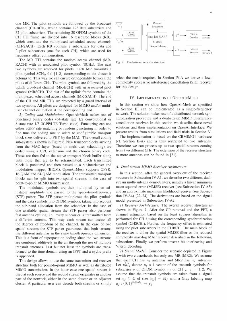
Fig. 7. Dual-stream receiver structure.
select the one it requires. In Section IV-A we derive a low-
complexity successive interference cancellation (SIC) receiver
for this design.
IV. IMPLEMENTATION OF OPENAIRMESH
In this section we show how OpenAirMesh as specified
in Section III can be implemented as a single-frequency
network. The solution makes use of a distributed network syn-
chronization procedure and a dual-stream MIMO interference
cancellation receiver. In this section we describe these novel
solutions and their implementation on OpenAirInterface. We
present results from simulations and field trials in Section V.
The implementation is based on the CBMIMO1 hardware
(cf. Section II-A) and is thus restricted to two antennas.
Therefore we can process up to two spatial streams coming
from two different CHs. The extension of the receiver structure
to more antennas can be found in [21].
A. Dual-stream MIMO Receiver Architecture
In this section, after the general overview of the receiver
structure in Subsection IV-A1, we describe two different dual-
stream multi-antenna demodulators, namely a linear minimum
mean squared error (MMSE) receiver (see Subsection IV-A3)
and an approximate maximum likelihood receiver (see Subsec-
tion IV-A4) [22–24]. The derivations are based on the signal
model presented in Subsection IV-A2.
1) Receiver Architecture: The overall receiver structure is
shown in Figure 7. After the CP removal and the FFT, a
channel estimation based on the least squares algorithm is
performed for CH i using the corresponding synchronization
symbol (CHSCHi). Further, the frequency offset is estimated
using the pilot subcarriers in the CHBCH. The main block of
the receiver is either the spatial MMSE filter or the reduced
complexity max-log MAP receiver described in the following
subsections. Finally we perform inverse bit interleaving and
Viterbi decoding.
2) Signal Model: Consider the scenario depicted in Figure
2 with two clusterheads but only one MR (MR2). We assume
that each CH has nt antennas and MR2 has nr antennas.
Let x(j)m,q denote nt × 1 vector of the transmit symbols for
subcarrier q of OFDM symbol m of CH j, j = 1, 2. We
assume that the transmit symbols are taken from a signal
set χj ⊆ C of size |χj | = Mj with a Gray labeling map
µj : {0, 1}log|Mj | → χj .

7
Binarycode
CRCAttachment
Binarycode
CRCAttachment
Binarycode
CRCAttachment
New Transportblock 0
New Transport
blockNnew
TB,n
2− 1
Binarycode
CRCAttachment
New Transportblock N
newTB,n
Spatial Stream 0
Spatial Stream 1
ActiveProcessBuffer
Active process map, New process count(NnewTB,n)
Puncturing(Rate
Matching)
Puncturing(Rate
Matching)
Puncturing(Rate
Matching)
Bit Interleav-ing/Modulation
Bit Interleav-ing/Modulation
×√
α
√1 − α
×
Spatial Stream 0
Spatial Stream 1
Sub-band allocation
New Transport
blockNnew
TB,n
2
Transportblock 0
TransportblockNTB,n
2− 1
TransportblockNTB−1
Puncturing(Rate
Matching)
TransportblockNTB
2
STFParsing
Pilot symbols
1
OFDM(IFFT+CPInsertion)
2
OFDM(IFFT+CPInsertion)
Fig. 6. OpenAirMesh Coded Modulation and HARQ.
Cascading the IFFT and the CP extension at the CHs and
the FFT and the CP removal at MR2, the received signal at
MR2 at q-th frequency tone and the m-th OFDM symbol can
be expressed as:
ym,q = H(1)q e2πjφ1mx(1)
m,q + H(2)q e2πjφ2mx(2)
m,q + zm,q (1)
where H(1)q and H
(2)q denote the nr × nt MIMO channel
between CH1 and MR2 and between CH2 and MR2. The
channel is assumed to be frequency selective (i.e., it varies
with subcarrier index q) and block fading (i.e., constant over
the OFDM symbols of a frame). φ1 is the frequency offset
between CH1 and MR2 and φ2 is the one between CH2 and
MR2 in radians (to convert them to Hertz, multiply by the
OFDM symbol rate). zm,q ∈ Cnr is the vector of circularly
symmetric complex white Gaussian noise of variance σ2.
Since each clusterhead transmits only one spatial stream and
antenna cycling is used, only one element of x(j)m,q, j = 1, 2 is
non-zero for every m and q. We identify this non-zero element
with x(j)m,q, j = 1, 2 and can rewrite (1) equivalently as
ym,q = h(1)q e2πjφ1mx(1)
q,m + h(2)q e2πjφ1mx(2)
m,q + zm,q, (2)
where h(1)q and h
(2)q are the equivalent channel vectors for
the non-zero elements. The complex symbols x(1)m,q, x
(2)m,q of
the 2 streams are assumed to be independent and of variances
σ21 and σ2
2 respectively. Assuming that the first stream is the
desired stream, the signal to noise ratio (SNR) is given by
σ21/σ2 and the signal to interference ratio (SIR) by σ2
1/σ22 .
3) MMSE Receiver: Linear spatial filters such as minimum
mean square error (MMSE) and zero forcing (ZF) filters can be
used to minimize the level of interference in the former case
while nulling out the interference in the latter case. Linear
MMSE filters exhibit better performance compared to ZF
ones and are thus being considered as favorable candidates
for future wireless systems [25, 26]. However, it is well
known that MMSE detection for non Gaussian alphabets in
low dimensional systems (low number of interferers) is sub-
optimal [27] and moreover MMSE detection cannot exploit
the interference structure.
The frequency domain MMSE filter Mq is given as
Mq =(σ2P−1 + HH
q Hq
)−1HH
q
where P is the diagonal power distribution matrix with the
diagonal as[σ2
1 , σ22
]and Hq =
[
h(1)q h
(2)q
]
.
The estimates of the transmitted symbols xm,q =[
x(1)m,q, x
(2)m,q
]T
are computed in three steps. Firstly, the fre-
quency offset needs to be compensated by computing y′m,q =
e−2πjφ1mym,q. Secondly the spatial filter Mq is applied to
y′m,q by computing xm,q = Mqy
′m,q. Finally an unbiasing
operation is performed by computing xm,q = Γ−1q xm,q where
Γq = diag (MqHq).
Post detection interference is assumed to be Gaussian which
on one hand reduces the computational complexity but on the
other adds to the sub-optimality of MMSE detection. MMSE
pre-processing decouples the spatial streams and the bit metric
for the i-th bit for bit value b of the symbol x(k)m,q on k-th
stream is given as
λik (ym,q, b) ≈ max
x(k)m,q∈χi
k,b
[
−γ2
k
N0
∣∣∣x(k)
m,q − x(k)m,q
∣∣∣
2]
(3)
for k = 1, 2 where γk is the i-th diagonal element of Γq. χik,b
denotes the subset of the signal set x(k)m,q ∈ χk whose labels
have the value b ∈ {0, 1} in the position i. Based on these bit
metrics, bit log likelihood ratios (LLRs) are calculated which
after de-interleaving are passed to the channel decoder.
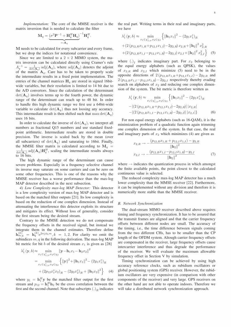
8
Implementation: The core of the MMSE receiver is the
matrix inversion that is needed to calculate the filter
Mq = (σ2P−1 + HHq Hq)
︸ ︷︷ ︸
=:Aq
−1HH
q .
M needs to be calculated for every subcarrier and every frame,
but we drop the indices for notational convenience.
Since we are limited to a 2 × 2 MIMO system, the ma-
trix inversion can be calculated directly using Cramer’s rule
A−1q = 1
det(Aq) adj(Aq), where adj(Aq) denotes the adjoint
of the matrix Aq. Care has to be taken to properly scale
the intermediate results in a fixed point implementation. The
entries of the channel matrices Hq are stored in signed 16bit-
wide variables, but their resolution is limited to 14 bit due to
the A/D convertors. Since the calculation of the determinant
det(Aq) involves terms up to the fourth power, the dynamic
range of the determinant can reach up to 48 bit. In order
to handle this high dynamic range we first use a 64bit-wide
variable to calculate det(Aq) thus not loosing any accuracy.
This intermediate result is then shifted such that max det(Aq)uses 16 bits.
In order to calculate the inverse of det(Aq), we interpret all
numbers as fractional Q15 numbers and use standard fixed-
point arithmetic. Intermediate results are stored in double
precision. The inverse is scaled back by the mean (over
all subcarriers) of det(Aq) and saturating to 16bit. Finally,
the MMSE filter matrix is calculated according to Mq =1
det(Aq) adj(Aq)HHq , scaling the intermediate results always
to 16 bits.
The high dynamic range of the determinant can cause
severe problems. Especially in a frequency selective channel
its inverse may saturate on some carriers and can be zero on
some other frequencies. This is one of the reasons why the
MMSE receiver has a worse performance than the max-log
MAP detector described in the next subsection.
4) Low Complexity max-log MAP Detector: This detector
is a low complexity version of max-log MAP detector and is
based on the matched filter outputs [21]. Its low complexity is
based on the reduction of one complex dimension. Instead of
attenuating the interference this detector exploits its structure
and mitigates its effect. Without loss of generality, consider
the first stream being the desired stream.
Contrary to the MMSE detection we do not compensate
the frequency offsets in the received signal, but instead we
integrate them in the channel estimates. Therefore define
h(k)m,q = h
(k)q e2πjφkm, k = 1, 2. For clarity we omit the
subindices m, q in the following derivation. The max-log MAP
bit metric for bit b of the desired stream x1 is given as [28]
λi1 (y, b)≈ min
x1∈χi1,b
,x2∈χ2
‖y−h1x1− h2x2‖2
= minx1∈χi
1,b,x2∈χ2
{
‖y‖2+‖h1x1‖
2− (2y1x∗1)R
+(2p12x∗1x2)R − (2y2x
∗2)R + ‖h2x2‖
2}
(4)
where y1 = hH1 y be the matched filter output for the first
stream and p12 = hH1 h2 be the cross correlation between the
first and the second channel. Note that subscripts (.)R indicates
the real part. Writing terms in their real and imaginary parts,
we have
λi1 (y, b) ≈ min
x1∈χi1,b
,x2∈χ2
{
‖h1x1‖2 − (2y1x
∗1)R
+(2 (p12,Rx1,R+p12,Ix1,I)−2y2,R) x2,R+‖h2‖2x2
2,R
+(2 (p12,Rx1,I−p12,Ix1,R)−2y2,I) x2,I +‖h2‖2x2
2,I
}
(5)
where (.)I indicates imaginary part. For x2 belonging to
the equal energy alphabets (such as QPSK), the values
of x2,R and x2,I which minimize (5) need to be in the
opposite directions of 2 (p12,Rx1,R+p12,Ix1,I)− 2y2,R and
2 (p12,Rx1,I−p12,Ix1,R)−2y2,I respectively thereby evading
search on alphabets of x2 and reducing one complex dimen-
sion of the system. The bit metric is therefore written as
λi1 (y, b) ≈ min
x1∈χi1,b
,x2∈χ2
{
‖h1x1‖2 − (2y1x
∗1)R
−|(2 (p12,Rx1,R+p12,Ix1,I)−2y2,R)| |x2,R|
−|(2 (p12,Rx1,I−p12,Ix1,R)−2y2,I)| |x2,I |} (6)
For non equal energy alphabets (such as 16-QAM), it is the
minimization problem of a quadratic function again trimming
one complex dimension of the system. In that case, the real
and imaginary parts of x2 which minimizes (4) are given as
x2,R → −(p12,Rx1,R + p12,Ix1,I) − y2,R
‖h2‖2
x2,I → −(p12,Rx1,I−p12,Ix1,R)−y2,I
‖h2‖2 (7)
where → indicates the quantization process in which amongst
the finite available points, the point closest to the calculated
continuous value is selected.
The reduced complexity max-log MAP detector has a much
lower complexity than the MMSE receiver [22]. Furthermore,
it can be implemented without any division and therefore it is
numerically more stable than the MMSE receiver.
B. Network Synchronization
The dual-stream MIMO receiver described above requires
timing and frequency synchronization. It has to be assured that
the transmit frames are aligned and that the carrier frequency
offsets between different nodes are small. The accuracy of
the timing, i.e., the time difference between signals coming
from the two different CHs, has to be smaller than the CP
length of the OFDM system. Altough carrier frequency offsets
are compensated in the receiver, large frequency offsets cause
intercarrier interference and thus degrade the performance
of the receiver. We will evaluate the maximum allowable
frequency offset in Section V by simulation.
Timing synchronization can be achieved by using high
accuracy reference clocks, such as rubidium oscillators or
global positioning system (GPS) receiver. However, the rubid-
ium oscillators are very expensive (in comparison with other
components of the receiver) and very large. GPS receivers on
the other hand are not able to operate indoors. Therefore we
will take a distributed network synchronization approach.

9
In nature, distributed synchronization scheme can be ob-
served on the flashing of fireflies [29]. Recently, this nature-
inspired scheme has been applied to synchronization in wire-
less networks [30–33]. However, most of these works consider
the isolated synchronization problem and neglect the actual
data communication. The pulse-coupled oscillator model (the
model inspired by firefly synchronization) assumes that nodes
have to be listening to all other nodes except during its own
transmission of the synchronization pulse and immediately
afterwards (refractory period). Therefore data transmission can
only take place in the refractory period. However, this period
must not be very long because otherwise the system becomes
unstable [32].
In OpenAirMesh we follow a similar approach as in [3]
for distributed timing synchronization. It is based on the two
physical channels CHSCH and MRSCH (see Table V) which
are transmitted in alternating TTIs from the CHs and MRs
respectively. Initially we declare one CH to be the primary CH,
which is the reference clock in the system. The primary CH
continuously sends out a synchronization signal (the CHSCH)
that allows every MR within the CH’s broadcast region to
synchronize to the network. As soon as a MR is synchronized
(i.e., when it can detect the CHBCH successfully), it sends
out a synchronization signal itself (the MRSCH). A secondary
CH not within the broadcast domain of the primary CH can
use the MRSCH to synchronize to the network. As soon as a
secondary CH is synchronized to the network, it also sends out
a CHSCH, allowing further MRs to synchronize, and so on. A
positive side-effect of this method is that several MRs form a
distributed antenna array when sending out the MRSCH. This
means that the secondary CH can benefit from this array gain
when detecting the MRSCH.
For the carrier phase synchronization, we use off-line
calibration prior to the system deployment. However, the
granularity of the calibration on the CBMIMO1 cards is in
the order of 500Hz, causing residual frequency offsets.
C. Integration
The dual-stream MIMO receiver and the distributed network
synchronization procedure described above enables the imple-
mentation of a single-frequency mesh network. Since all CHs
are synchronized and transmit on the same frequency, MRs
that are in the broadcast domain of two such clusters must
use the dual-stream MIMO receiver to decode the CHBCHs
of both CHs concurrently. But the receiver can also be used
for the SACH (both in the uplink and in the downlink)
allowing the CHs to schedule their resources independently
(and thus significantly reducing the signalling overhead). For
the downlink SACH, the receiver is used exactly the same
way as for the CHBCH. On the uplink the MR transmit two
independent data streams as described in Section III-C2 and
the CHs decode only the stream dedicated for them, treating
the other one as interference.
V. EXPERIMENTS AND RESULTS
In this section we investigate the performance of the
two dual-stream receiver structures described in the previous
section. Firstly, in Subsection V-A, we perform computer
simulations of the two receiver structures using a simple syn-
thetic channel model. Secondly, in Subsection V-B we present
performance results from the real-time implementation on the
OpenAirInterface platform. Last but not least, in Subsection
V-C we present field trial experiments that were conducted
within the CHORIST project4 close to Barcelona, Spain in
February 2009.
All performance comparisons (both for simulation and lab
tests) were done using the broadcast channel (BCH) of the
primary clusterhead (CH1) with interference from the BCH
from the secondary clusterhead (CH2). The BCH uses QPSK
modulation and rate 1/2 convolutional code. The block length
is 1056bits, which corresponds to 8 OFDM symbols with 132
data subcarriers each. We use 2 antennas on all nodes.
A. Computer Simulations
In the computer simulations we isolate and study the
effect of the following phenomena on the performance of
the receiver: (i) channel state information at the receiver
(CSIR), (ii) frequency selective fading vs. frequency flat
fading, (iii) Rayleigh fading vs. Ricean fading, (iv) receive
antenna correlation, and (v) frequency offsets.
1) Channel Model: For the simulations the 2 × 2 MIMO
channel matrices H(1)q and H
(2)q are modeled as spatially white
and independent. The channel is assumed to be constant during
a block and varies independently between blocks. We use
both a frequency flat fading model as well as a frequency
selective model. In the frequency flat case the channel matrices
stay constant over all subcarriers q with channel coefficients
drawn from a Rayleigh distribution with unit variance. In the
frequency selective case we model the channel as a tapped
delay line with 8 sample-spaced taps with an exponential
decaying power delay profile. Each tap undergoes Rayleigh
fading. If line-of-sight (LOS) is present, the first tap undergoes
Ricean fading. Receive correlation is modeled by multiplying
(from the left) the MIMO channel matrices with the square
root of the receive correlation matrix RRx =( 1 ρ
ρ 1
).
2) Simulation Results: The two receiver structures de-
scribed in Section IV-A were implemented in fixed-point
C. The simulation model follows the model (1) with the
difference that the C simulator includes the IFFT and CP
insertion at the transmitter and the corresponding FFT and
CP removal at the receiver. The channel is thus simulated in
the time domain rather than in the frequency domain. Further,
we can simulate carrier frequency offsets. By not adding any
noise on the pilot symbols we can also simulate the case of
perfect CSIR. This allows us to study the impact of imperfect
channel estimates on the two receiver structures.
We perform Monte Carlo simulations with the MMSE
receiver and the max-log MAP receiver. We fix the SNR for the
first stream and vary the interference from the second stream
on the y-axis. Each figure shows the frame error rates of the
first stream for both receivers and several SNR values. We
only show a representative subset of the simulation results:
4http://www.chorist.eu
10
−10 −8 −6 −4 −2 0 2 4 610
−4
10−3
10−2
10−1
100
Interference [dB]
FE
R S
trea
m 1
MMSE, SNR=5dBMMSE, SNR=10dBMMSE, SNR=15dBmax−log MAP, SNR=5dBmax−log MAP, SNR=10dBmax−log MAP, SNR=15dB
Fig. 8. Frame error rate of the first stream of the of the MMSE and max-logMAP receiver for a frequency flat Rayleigh fading channel with perfect CSIR.Results are plotted for different SNR levels of the first stream. The x axisdenotes the interference of the second stream w.r.t. the first stream.
−10 −8 −6 −4 −2 0 2 4 610
−3
10−2
10−1
100
Interference [dB]
FE
R S
trea
m 1
MMSE, SNR=5dBMMSE, SNR=10dBMMSE, SNR=15dBmax−log MAP, SNR=5dBmax−log MAP, SNR=10dBmax−log MAP, SNR=15dB
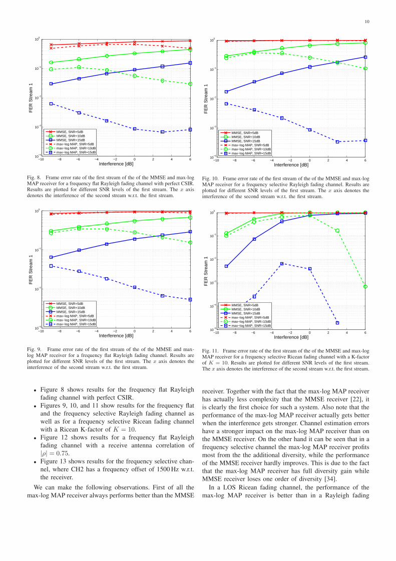
Fig. 9. Frame error rate of the first stream of the of the MMSE and max-log MAP receiver for a frequency flat Rayleigh fading channel. Results areplotted for different SNR levels of the first stream. The x axis denotes theinterference of the second stream w.r.t. the first stream.
• Figure 8 shows results for the frequency flat Rayleigh
fading channel with perfect CSIR.
• Figures 9, 10, and 11 show results for the frequency flat
and the frequency selective Rayleigh fading channel as
well as for a frequency selective Ricean fading channel
with a Ricean K-factor of K = 10.
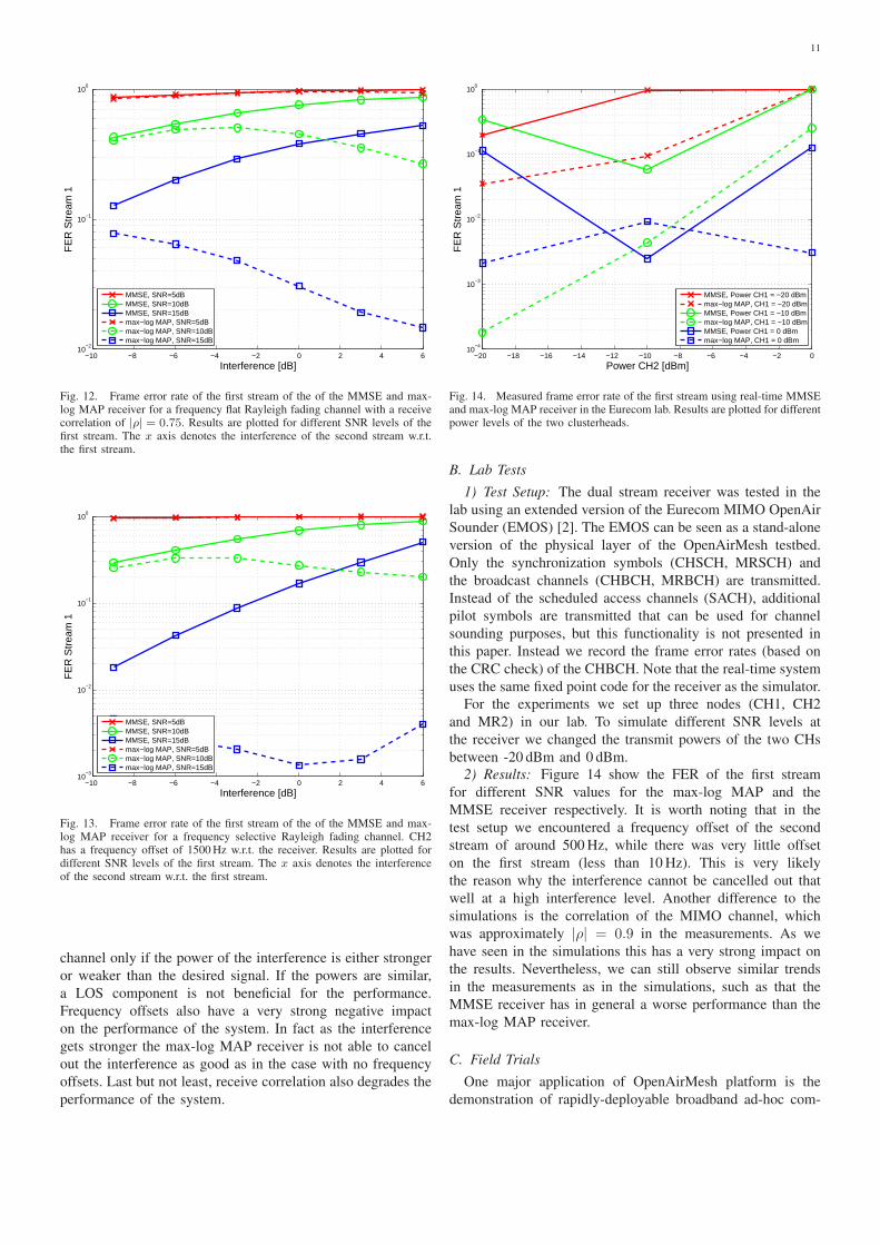
• Figure 12 shows results for a frequency flat Rayleigh
fading channel with a receive antenna correlation of
|ρ| = 0.75.
• Figure 13 shows results for the frequency selective chan-
nel, where CH2 has a frequency offset of 1500 Hz w.r.t.
the receiver.
We can make the following observations. First of all the
max-log MAP receiver always performs better than the MMSE
−10 −8 −6 −4 −2 0 2 4 610
−4
10−3
10−2
10−1
100
Interference [dB]
FE
R S
trea
m 1
MMSE, SNR=5dBMMSE, SNR=10dBMMSE, SNR=15dBmax−log MAP, SNR=5dBmax−log MAP, SNR=10dBmax−log MAP, SNR=15dB
Fig. 10. Frame error rate of the first stream of the of the MMSE and max-logMAP receiver for a frequency selective Rayleigh fading channel. Results areplotted for different SNR levels of the first stream. The x axis denotes theinterference of the second stream w.r.t. the first stream.
−10 −8 −6 −4 −2 0 2 4 610
−5
10−4
10−3
10−2
10−1
100
Interference [dB]
FE
R S
trea
m 1
MMSE, SNR=5dBMMSE, SNR=10dBMMSE, SNR=15dBmax−log MAP, SNR=5dBmax−log MAP, SNR=10dBmax−log MAP, SNR=15dB
Fig. 11. Frame error rate of the first stream of the of the MMSE and max-logMAP receiver for a frequency selective Ricean fading channel with a K-factorof K = 10. Results are plotted for different SNR levels of the first stream.The x axis denotes the interference of the second stream w.r.t. the first stream.
receiver. Together with the fact that the max-log MAP receiver
has actually less complexity that the MMSE receiver [22], it
is clearly the first choice for such a system. Also note that the
performance of the max-log MAP receiver actually gets better
when the interference gets stronger. Channel estimation errors
have a stronger impact on the max-log MAP receiver than on
the MMSE receiver. On the other hand it can be seen that in a
frequency selective channel the max-log MAP receiver profits
most from the the additional diversity, while the performance
of the MMSE receiver hardly improves. This is due to the fact
that the max-log MAP receiver has full diversity gain while
MMSE receiver loses one order of diversity [34].
In a LOS Ricean fading channel, the performance of the
max-log MAP receiver is better than in a Rayleigh fading
11
−10 −8 −6 −4 −2 0 2 4 610
−2
10−1
100
Interference [dB]
FE
R S
trea
m 1
MMSE, SNR=5dBMMSE, SNR=10dBMMSE, SNR=15dBmax−log MAP, SNR=5dBmax−log MAP, SNR=10dBmax−log MAP, SNR=15dB
Fig. 12. Frame error rate of the first stream of the of the MMSE and max-log MAP receiver for a frequency flat Rayleigh fading channel with a receivecorrelation of |ρ| = 0.75. Results are plotted for different SNR levels of thefirst stream. The x axis denotes the interference of the second stream w.r.t.the first stream.
−10 −8 −6 −4 −2 0 2 4 610
−3
10−2
10−1
100
Interference [dB]
FE
R S
trea
m 1
MMSE, SNR=5dBMMSE, SNR=10dBMMSE, SNR=15dBmax−log MAP, SNR=5dBmax−log MAP, SNR=10dBmax−log MAP, SNR=15dB
Fig. 13. Frame error rate of the first stream of the of the MMSE and max-log MAP receiver for a frequency selective Rayleigh fading channel. CH2has a frequency offset of 1500 Hz w.r.t. the receiver. Results are plotted fordifferent SNR levels of the first stream. The x axis denotes the interferenceof the second stream w.r.t. the first stream.
channel only if the power of the interference is either stronger
or weaker than the desired signal. If the powers are similar,
a LOS component is not beneficial for the performance.
Frequency offsets also have a very strong negative impact
on the performance of the system. In fact as the interference
gets stronger the max-log MAP receiver is not able to cancel
out the interference as good as in the case with no frequency
offsets. Last but not least, receive correlation also degrades the
performance of the system.
−20 −18 −16 −14 −12 −10 −8 −6 −4 −2 010
−4
10−3
10−2
10−1
100
Power CH2 [dBm]
FE
R S
trea
m 1
MMSE, Power CH1 = −20 dBmmax−log MAP, CH1 = −20 dBmMMSE, Power CH1 = −10 dBmmax−log MAP, CH1 = −10 dBmMMSE, Power CH1 = 0 dBmmax−log MAP, CH1 = 0 dBm
Fig. 14. Measured frame error rate of the first stream using real-time MMSEand max-log MAP receiver in the Eurecom lab. Results are plotted for differentpower levels of the two clusterheads.
B. Lab Tests
1) Test Setup: The dual stream receiver was tested in the
lab using an extended version of the Eurecom MIMO OpenAir
Sounder (EMOS) [2]. The EMOS can be seen as a stand-alone
version of the physical layer of the OpenAirMesh testbed.
Only the synchronization symbols (CHSCH, MRSCH) and
the broadcast channels (CHBCH, MRBCH) are transmitted.
Instead of the scheduled access channels (SACH), additional
pilot symbols are transmitted that can be used for channel
sounding purposes, but this functionality is not presented in
this paper. Instead we record the frame error rates (based on
the CRC check) of the CHBCH. Note that the real-time system
uses the same fixed point code for the receiver as the simulator.
For the experiments we set up three nodes (CH1, CH2
and MR2) in our lab. To simulate different SNR levels at
the receiver we changed the transmit powers of the two CHs
between -20 dBm and 0 dBm.
2) Results: Figure 14 show the FER of the first stream
for different SNR values for the max-log MAP and the
MMSE receiver respectively. It is worth noting that in the
test setup we encountered a frequency offset of the second
stream of around 500 Hz, while there was very little offset
on the first stream (less than 10 Hz). This is very likely
the reason why the interference cannot be cancelled out that
well at a high interference level. Another difference to the
simulations is the correlation of the MIMO channel, which
was approximately |ρ| = 0.9 in the measurements. As we
have seen in the simulations this has a very strong impact on
the results. Nevertheless, we can still observe similar trends
in the measurements as in the simulations, such as that the
MMSE receiver has in general a worse performance than the
max-log MAP receiver.
C. Field Trials
One major application of OpenAirMesh platform is the
demonstration of rapidly-deployable broadband ad-hoc com-
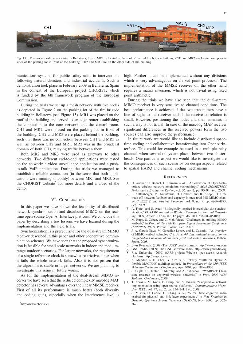
12
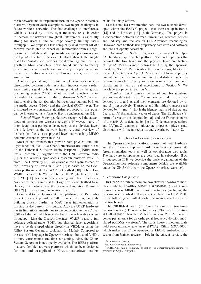
Fig. 15. Five node mesh network trial in Bellaterra, Spain. MR1 is located at the roof of the red fire brigade building. CH1 and MR2 are located on oppositesides of the parking lot in front of the building. CH2 and MR3 are on the other side of the building.
munications systems for public safety units in interventions
following natural disasters and industrial accidents. Such a
demonstration took place in February 2009 in Bellaterra, Spain
in the context of the European project CHORIST, which
is funded by the 6th framework program of the European
Commission.
During the trials we set up a mesh network with five nodes
as depicted in Figure 2 on the parking lot of the fire brigade
building in Bellaterra (see Figure 15). MR1 was placed on the
roof of the building and served as an edge router establishing
the connection to the core network and the control room.
CH1 and MR2 were placed on the parking lot in front of
the building. CH2 and MR3 were placed behind the building,
such that there was no connection between CH1 and MR3 as
well as between CH2 and MR1. MR2 was in the broadcast
domain of both CHs, relaying traffic between them.
Both MR2 and MR3 were used as gateways to other
networks. Two different end-to-end applications were tested
on the network: a video surveillance application and a push-
to-talk VoIP application. During the trials we managed to
establish a reliable connection (in the sense that both appli-
cations were running smoothly) between MR1 and MR3. See
the CHORIST website5 for more details and a video of the
demo.
VI. CONCLUSIONS
In this paper we have shown the feasibility of distributed
network synchronization and distributed MIMO on the real-
time open-source OpenAirInterface platform. We conclude this
paper by describing a few lessons we have learned during the
implementation and the field trials.
Synchronization is a prerequisite for the dual-stream MIMO
receiver described in this paper and other cooperative commu-
nication schemes. We have seen that the proposed synchroniza-
tion is feasible for small scale networks in indoor and medium-
range outdoor scenarios. For larger networks, the requirement
of a single reference clock is somewhat restrictive, since when
it fails the whole network fails. Also it is not proven that
the algorithm is stable in larger networks. We are planning to
investigate this issue in future works.
As for the implementation of the dual-stream MIMO re-
ceiver we have seen that the reduced complexity max-log MAP
detector has several advantages over the linear MMSE receiver.
First of all its performance is much better (both diversity
and coding gain), especially when the interference level is
5http://www.chorist.eu
high. Further it can be implemented without any divisions
which is very advantageous on a fixed point processor. The
implementation of the MMSE receiver on the other hand
requires a matrix inversion, which is not trivial using fixed
point arithmetic.
During the trials we have also seen that the dual-stream
MIMO receiver is very sensitive to channel conditions. The
best performance is achieved if the two transmitters have a
line of sight to the receiver and if the receive correlation is
small. However, positioning the nodes and their antennas in
such a way is not trivial. In case of the max-log MAP receiver
significant differences in the received powers form the two
sources can also improve the performance.
In future work we would like to include distributed space-
time coding and collaborative beamforming into OpenAirIn-
terface. This could for example be used in a multiple relay
channel, when several relays are placed between two cluster-
heads. One particular aspect we would like to investigate are
the consequences of such scenarios on design aspects related
to spatial HARQ and channel coding mechanisms.
REFERENCES
[1] H. Anouar, C. Bonnet, D. Camara et al., “An overview of OpenAirIn-terface wireless network emulation methodology,” ACM SIGMETRICS
Performance Evaluation Review, vol. 36, no. 2, pp. 90–94, Sep. 2008.[2] F. Kaltenberger, M. Kountouris, D. Gesbert, and R. Knopp, “On the
trade-off between feedback and capacity in measured MU-MIMO chan-nels,” IEEE Trans. Wireless Commun., vol. 8, no. 9, pp. 4866–4875,Sep. 2009.
[3] A. Tyrrell and G. Auer, “Biologically inspired intercellular slot synchro-nization,” EURASIP Journal on Wireless Communications and Network-
ing, 2009, Article ID 854087, 12 pages, doi:10.1155/2009/854087.[4] M. Rupp, S. Caban, and C. Mehlfuhrer, “Challenges in building MIMO
testbeds,” in Proc. of the 13th European Signal Processing Conference
(EUSIPCO 2007), Poznan, Poland, Sep. 2007.[5] J. A. Garcıa-Naya, M. Gonzalez-Lopez, and L. Castedo, “An overview
of MIMO testbed technology,” in Proc. 4th International Symposium on
Image/Video Communications over fixed and mobile networks, Bilbao,Spain, 2008.
[6] Ettus Research. (2009) The USRP product family. http://www.ettus.com[7] GNU Radio. (2009) The GNU software radio. http://www.gnuradio.org[8] Rice University. (2009) WARP project: Wireless open-access research
platform. http://warp.rice.edu[9] K. Mandke, S.-H. Choi, G. Kim et al., “Early results on Hydra: A
flexible MAC/PHY multihop testbed,” in Proceedings of the 65th IEEE
Vehicular Technology Conference, Apr. 2007, pp. 1896–1900.[10] S. Gupta, C. Hunter, P. Murphy, and A. Sabharwal, “WARPnet: Clean
slate research on deployed wireless networks,” in Proc. 2009 ACM
Mobihoc Conference, 2009.[11] T. Korakis, M. Knox, E. Erkip, and S. Panwar, “Cooperative network
implementation using open-source platforms,” Communications Maga-
zine, IEEE, vol. 47, no. 2, pp. 134–141, Feb. 2009.[12] S. Mishra, D. Cabric, C. Chang et al., “A real time cognitive radio
testbed for physical and link layer experiments,” in New Frontiers in
Dynamic Spectrum Access Networks (DySPAN), Nov. 2005, pp. 562–567.
13
[13] C. Chang, J. Wawrzynek, and R. Brodersen, “BEE2: a high-end re-configurable computing system,” Design & Test of Computers, IEEE,vol. 22, no. 2, pp. 114–125, March-April 2005.
[14] Fraunhofer Institute for Telecommunications (Heinrich-Hertz-Institut).(2009) Berlin LTE-Advanced Testbed. http://www.hhi.fraunhofer.de/en/departments/broadband-mobile-communication-networks/department-overview/berlin-lte-advanced-testbed/
[15] R. Irmer, H.-P. Mayer, A. Weber et al., “Multisite field trial for LTE andadvanced concepts,” Communications Magazine, IEEE, vol. 47, no. 2,pp. 92–98, Feb. 2009.
[16] Gaisler Research. (2009) Leon3 processor. http://www.gaisler.com[17] N.-u.-I. Muhammad, R. Rasheed, R. Pacalet et al., “Flexible baseband
architectures for future wireless systems,” in Proc. 11th EUROMICRO
Conference on Digital System Design Architectures, Methods and Tools
DSD ’08, 2008, pp. 39–46.[18] H. Anouar, C. Bonnet, F. Kaltenberger, and R. Knopp, “OpenAirMesh—
an experimental platform for cooperative mesh networks,” in Proc.
1st COST2100 Workshop on MIMO and Cooperative Communications,Trondheim, Norway, Jun. 2008.
[19] R. Knopp, “Detailed report on broadband prototype implementationand updated system specifications,” CHORIST, Project DeliverableSP4.D11, Jul. 2009. http://www.chorist.eu
[20] M. Realp, A. Perez-Neira, and R. Knopp, “Delay bounds for resourceallocation in wideband wireless systems,” in Proc. IEEE International
Conference on Communications (ICC ’06), vol. 10, Jun. 2006, pp. 4385–4390.
[21] R. Ghaffar and R. Knopp, “Interference suppression for next generationwireless systems,” in Proc. IEEE Vehicular Technology Conference VTC-
Spring, Barcelona, Spain, Apr. 2009.[22] R. Ghaffar and R. Knopp, “Dual-antenna BICM reception with appli-
cations to MIMO broadcast and single frequency cellular system,” inProc. IEEE Intl. Symposium on Personal, Indoor and Mobile Radio
Communications (PIMRC), Cannes, France, Sep. 2008.[23] R. Ghaffar and R. Knopp, “A MIMO broadcast strategy and interference
cancellation in single frequency cellular system,” in Proc. 1st COST2100
Workshop on MIMO and Cooperative Communications, Trondheim,Norway, Jun. 2008.
[24] F. Kaltenberger, R. Ghaffar, and R. Knopp, “Low-complexity distributedMIMO receiver and its implementation on the OpenAirInterface plat-form,” in Proc. IEEE Int. Symp. on Pers., Indoor and Mobile Radio
Comm. (PIMRC), Tokyo, Japan, Sep. 2009.[25] E. Dahlman, H. Ekstrom, A. Furuskar et al., “The 3G long-term
evolution - radio interface concepts and performance evaluation,” inProc. IEEE 63rd Vehicular Technology Conference VTC-Spring, vol. 1,May 2006, pp. 137–141.
[26] I. Medvedev, B. Bjerke, R. Walton et al., “A comparison of MIMOreceiver structures for 802.11n WLAN - performance and complexity,”in Proc. IEEE 17th International Symposium on Personal, Indoor and
Mobile Radio Communications, Sept. 2006.[27] H. Poor and S. Verdu, “Probability of error in MMSE multiuser
detection,” IEEE Trans. Inf. Theory, vol. 43, no. 3, pp. 858–871, May1997.
[28] G. Caire, G. Taricco, and E. Biglieri, “Bit-interleaved coded modula-tion,” IEEE Trans. Inf. Theory, vol. 44, no. 3, pp. 927–946, May 1998.
[29] J. Buck and E. Buck, “Synchronous fireflies,” Scientific American, vol.234, no. 5, pp. 74–85, May 1976.
[30] O. Simeone, U. Spagnolini, Y. Bar-Ness, and S. Strogatz, “Distributedsynchronization in wireless networks,” IEEE Signal Process. Mag.,vol. 25, no. 5, pp. 81–97, Sep. 2008.
[31] A. Tyrrell, G. Auer, and C. Bettstetter, “Fireflies as role models forsynchronization in ad hoc networks,” in Proc. Bio inspired models
of network, information and computing systems (BIONETICS ’06),Cavalese, Italy, 2006.
[32] Y.-W. Hong and A. Scaglione, “A scalable synchronization protocol forlarge scale sensor networks and its applications,” IEEE J. Sel. Areas
Commun., vol. 23, no. 5, pp. 1085–1099, May 2005.[33] A. S. Hu and S. D. Servetto, “On the scalability of cooperative time
synchronization in pulse-connected networks,” IEEE Trans. Inf. Theory,vol. 52, no. 6, pp. 2725–2748, Jun. 2006.
[34] R. Ghaffar and R. Knopp, “Spatial interference cancellation and pairwiseerror probability analysis,” in Proc. IEEE International Conference on
Communications (ICC), Dresden, Germany, Jun. 2009.