Embed Size (px)
Citation preview

Design and Implementation of Adaptive Vibration Filter
for MEMS Based Low Cost IMU
Ufuk GÜNER1, Hüseyin CANBOLAT1, Ali ÜNLÜTÜRK2
1Electric Electronic Engineering, Yıldırım Beyazıt University, Turkey
[email protected], [email protected] 2 Electric Electronic Engineering, Selcuk University, Turkey
Abstract
Abstract— In this work, an adaptive vibration filter was
designed for Micro Electro-Mechanical System (MEMS) based
low cost Inertial Measurement Unit (IMU). Designed IMU has
ten degree freedom. It consists of three axis accelerometer, three
axis gyroscope, three axis magnetometer and one axis
barometric pressure sensor. All sensors are connected to Cortex
M3 based microcontroller. Kalman Filter was used as sensor
fusion algorithm. Although Kalman filter could overcome many
noise sources, it could give undesirable output signal when
sensors, which are combined with Kalman filter, were affected
by simultaneously same noise like as vibration noise. So in
order to overcome the vibration affection of IMU, an Adaptive
Noise Canceller (ANC) was designed and implemented for the
IMU. In addition, an experimental setup was built to compare
the IMU output with and without ANC.
Keywords—Adaptive Vibration Filter, Adaptive Noise
Canceller, Kalman Filter, IMU, MEMS sesnsor
1. Introduction
A physical system, which can move in free space, needs
control to follow desired trajectory. Therefore, accurate
orientation measurements are necessary to control these kinds of
systems. Inertial Measurement Unit (IMU) is an essential device
which is used for orientation measurement. An IMU can be
designed with different types of sensors. Sensor based
electronics, mechanics, optics are commonly used for IMU
design. In last decade, Micro-Electro-Mechanical System
(MEMS) types of sensors have very wide usage area because of
its inexpensiveness and fast fabrication. Nowadays, in almost
every smart phones, many navigation and robotic systems,
MEMS sensors are used to measure the orientation. Despite of
the wide usage of MEMS sensors, their measurements are
corrupted from many noise sources
MEMS based IMU needs three different sensors to measure
three axis orientation angle changes. Gyroscope, accelerometer
and magnetometer are MEMS based sensor which are
commonly used for IMU design. Accelerometer sensors are able
to measure applied acceleration on its axis. In other words
accelerometer can measure orientations change with using
gravitational force vector. However, these sensors are capable
of only measuring two axis orientations angle change because of
gravitational vector intersect of only two planes. So
accelerometer sensors generally are applied to roll and pitch
measurements. MEMS based accelerometer is very sensitive to
environmental noise. Therefore, this sensor doesn’t provide
reliable orientation measurements. Gyroscope is another sensor
which can measure angular rate change on its axis. This sensor
is capable of measuring three axis orientation angle changes.
However, MEMS based gyroscope does not provide reliable
orientation measurement because of bias drift problem. Thus,
fusion of accelerometer and gyroscope makes it available to
avoid noise and bias drift error. But this sensor group can only
measure roll and pitch change. So another sensor is needed to
combine with gyroscope for measuring yaw angle.
Magnetometer is a general yaw sensor which works like
compass and it can measure magnetic field of earth. Fusion of
magnetometer and gyroscope provides more reliable yaw
measurement.
Kalman filter is a common sensor fusion algorithm. It is very
widely used for IMU systems. In this work, linear Kalman filter
algorithm was used for sensor fusion. Although, Kalman filter
could overcome many structural and environmental noises,
when sensors, in fusion algorithm, were affected simultaneously
by same noise, Kalman filter could not eliminate this type noise,
such as vibration. Both gyroscope and accelerometer are
affected by vibration. Therefore, the IMU needs mechanical and
software based vibration filter. In this work an adaptive filter
was implemented on the IMU for software based vibration filter.
Adaptive filter is a mathematical tool which provides
modelling of two signals in real time. Adaptive filter is based on
the input and output structure of a signal. Its parameter is altered
with the input-output correlation to provide desired signal
output. An adaptive filter often consists of two parts. They are
linear filter and adaptation algorithm. Finite Impulse Response
(FIR), and Infinite Impulse Response (IIR) filters are most often
linear filter parts of the adaptive filters. Least Mean Square
(LMS), Mean Square Error (MSE) are most often used for
adaptation algorithm of the adaptive filters [1]. There are many
application of adaptive filter such as system identification,
inverse modelling, linear prediction, feedforward control and
Adaptive Noise Canceller (ANC). In this work, an ANC
algorithm was implemented using LMS and FIR.
2. Sensors and Hardware of IMU
The designed IMU has four MEMS based sensor. MPU6050
is used for Gyroscope and Accelerometer. HMC5883L, another
sensor, is an electronic compass. And last sensor in the IMU is
BMP085, a barometric pressure sensor. Gyroscope and
accelerometer sensors are in the same package in MPU6050.
130
Both sensors, inside the MPU6050, have 16 bit Analog Digital
Converter (ADC). The MPU6050 can give digital output
directly. Gyroscope is used for three axis angular velocity
measurement and accelerometer is used for gravitational force
vector measurement in two planes. HMC5883L is a three axis
magnetometer sensor. This sensor can measure the strength and
direction of the local magnetic field. The magnetometer sensor
can define the yaw angle with respect to North Pole of the Earth.
BMP085 is a one axis barometric pressure sensor, which is
capable of measuring altitude by using air pressure and
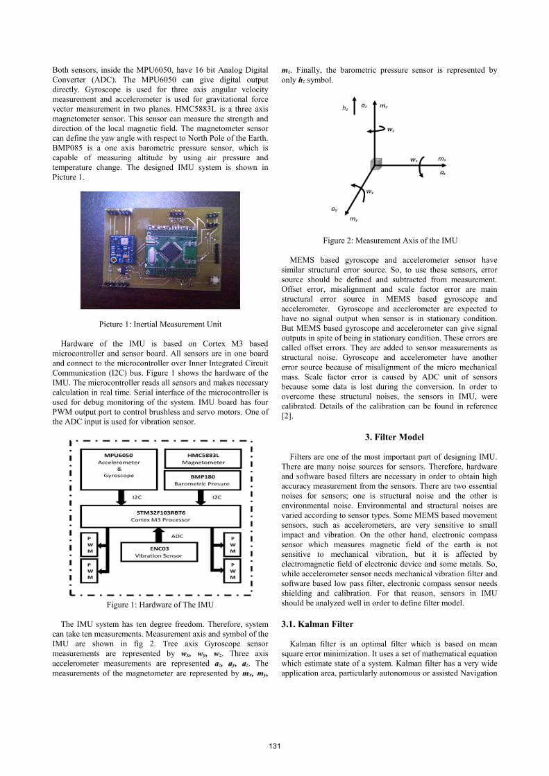
temperature change. The designed IMU system is shown in
Picture 1.
Picture 1: Inertial Measurement Unit
Hardware of the IMU is based on Cortex M3 based
microcontroller and sensor board. All sensors are in one board
and connect to the microcontroller over Inner Integrated Circuit
Communication (I2C) bus. Figure 1 shows the hardware of the
IMU. The microcontroller reads all sensors and makes necessary
calculation in real time. Serial interface of the microcontroller is
used for debug monitoring of the system. IMU board has four
PWM output port to control brushless and servo motors. One of
the ADC input is used for vibration sensor.
Figure 1: Hardware of The IMU
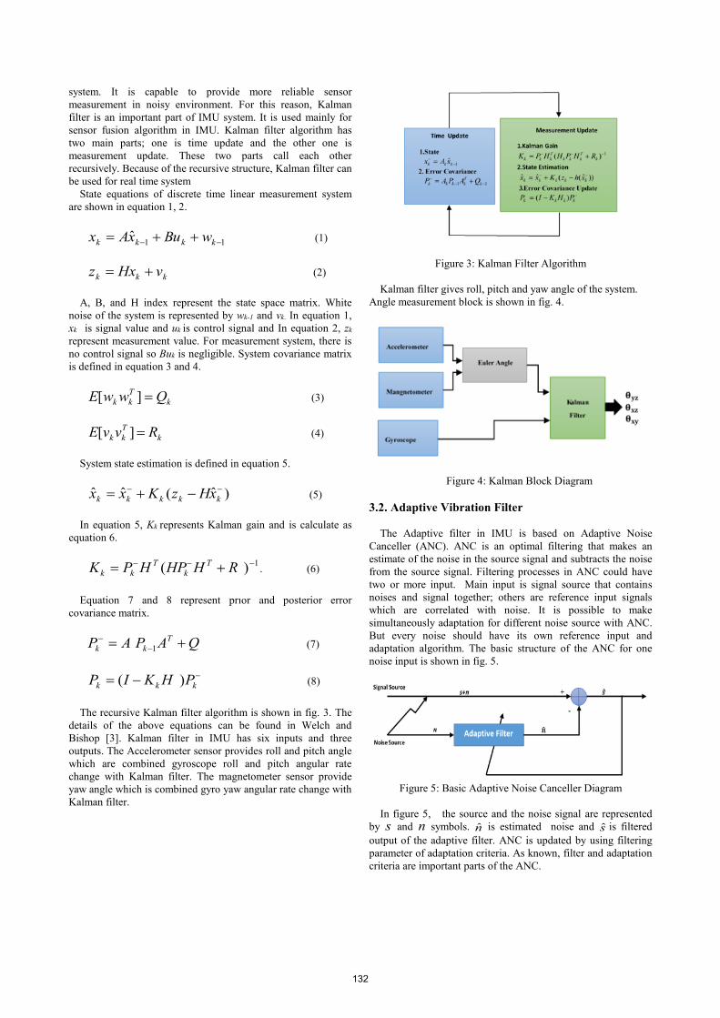
The IMU system has ten degree freedom. Therefore, system
can take ten measurements. Measurement axis and symbol of the
IMU are shown in fig 2. Tree axis Gyroscope sensor
measurements are represented by wx, wy, wz. Three axis
accelerometer measurements are represented az, ay, az. The
measurements of the magnetometer are represented by mx, my,
mz. Finally, the barometric pressure sensor is represented by
only hz symbol.
Figure 2: Measurement Axis of the IMU
MEMS based gyroscope and accelerometer sensor have
similar structural error source. So, to use these sensors, error
source should be defined and subtracted from measurement.
Offset error, misalignment and scale factor error are main
structural error source in MEMS based gyroscope and
accelerometer. Gyroscope and accelerometer are expected to
have no signal output when sensor is in stationary condition.
But MEMS based gyroscope and accelerometer can give signal
outputs in spite of being in stationary condition. These errors are
called offset errors. They are added to sensor measurements as
structural noise. Gyroscope and accelerometer have another
error source because of misalignment of the micro mechanical
mass. Scale factor error is caused by ADC unit of sensors
because some data is lost during the conversion. In order to
overcome these structural noises, the sensors in IMU, were
calibrated. Details of the calibration can be found in reference
[2].
3. Filter Model
Filters are one of the most important part of designing IMU.
There are many noise sources for sensors. Therefore, hardware
and software based filters are necessary in order to obtain high
accuracy measurement from the sensors. There are two essential
noises for sensors; one is structural noise and the other is
environmental noise. Environmental and structural noises are
varied according to sensor types. Some MEMS based movement
sensors, such as accelerometers, are very sensitive to small
impact and vibration. On the other hand, electronic compass
sensor which measures magnetic field of the earth is not
sensitive to mechanical vibration, but it is affected by
electromagnetic field of electronic device and some metals. So,
while accelerometer sensor needs mechanical vibration filter and
software based low pass filter, electronic compass sensor needs
shielding and calibration. For that reason, sensors in IMU
should be analyzed well in order to define filter model.
3.1. Kalman Filter
Kalman filter is an optimal filter which is based on mean
square error minimization. It uses a set of mathematical equation
which estimate state of a system. Kalman filter has a very wide
application area, particularly autonomous or assisted Navigation
131
system. It is capable to provide more reliable sensor
measurement in noisy environment. For this reason, Kalman
filter is an important part of IMU system. It is used mainly for
sensor fusion algorithm in IMU. Kalman filter algorithm has
two main parts; one is time update and the other one is
measurement update. These two parts call each other
recursively. Because of the recursive structure, Kalman filter can
be used for real time system
State equations of discrete time linear measurement system
are shown in equation 1, 2.
11ˆ
kkkk wBuxAx (1)
kkk vHxz (2)
A, B, and H index represent the state space matrix. White
noise of the system is represented by wk-1 and vk. In equation 1,
xk is signal value and uk is control signal and In equation 2, zk
represent measurement value. For measurement system, there is
no control signal so Buk is negligible. System covariance matrix
is defined in equation 3 and 4.
k
T
kk QwwE ][ (3)
k
T
kk RvvE ][ (4)
System state estimation is defined in equation 5.
)ˆ(ˆˆ kkkkk xHzKxx (5)
In equation 5, Kk represents Kalman gain and is calculate as
equation 6.
1)( RHHPHPK T
k
T
kk . (6)
Equation 7 and 8 represent prıor and posterior error
covariance matrix.
QAPAP T
kk
1 (7)
kkk PHKIP )( (8)
The recursive Kalman filter algorithm is shown in fig. 3. The
details of the above equations can be found in Welch and
Bishop [3]. Kalman filter in IMU has six inputs and three
outputs. The Accelerometer sensor provides roll and pitch angle
which are combined gyroscope roll and pitch angular rate
change with Kalman filter. The magnetometer sensor provide
yaw angle which is combined gyro yaw angular rate change with
Kalman filter.
Figure 3: Kalman Filter Algorithm
Kalman filter gives roll, pitch and yaw angle of the system.
Angle measurement block is shown in fig. 4.
Figure 4: Kalman Block Diagram
3.2. Adaptive Vibration Filter
The Adaptive filter in IMU is based on Adaptive Noise
Canceller (ANC). ANC is an optimal filtering that makes an
estimate of the noise in the source signal and subtracts the noise
from the source signal. Filtering processes in ANC could have
two or more input. Main input is signal source that contains
noises and signal together; others are reference input signals
which are correlated with noise. It is possible to make
simultaneously adaptation for different noise source with ANC.
But every noise should have its own reference input and
adaptation algorithm. The basic structure of the ANC for one
noise input is shown in fig. 5.
Figure 5: Basic Adaptive Noise Canceller Diagram
In figure 5, the source and the noise signal are represented
by s and n symbols. n is estimated noise and s is filtered
output of the adaptive filter. ANC is updated by using filtering
parameter of adaptation criteria. As known, filter and adaptation
criteria are important parts of the ANC.
132

The criteria are generally based on the minimization of the
error. Different types of algorithm could be used for the
minimization criteria. e.g. Least Mean Squares (LMS)
algorithm, the Recursive Least Squares (RLS) algorithm,
Normalized least Mean Squares(NLMS) etc. In IMU, LMS was
implemented for adaptation criteria. Because LMS is
computationally easy and could be applied on real time data
simultaneously [4, 5]. In addition, for filtering, FIR was chosen.
Adaptive filter structure could be seen in fig. 6. LMS update the
FIR filter coefficient using step descent algorithm.
Figure 6: ANC Block In IMU
Basic FIR filtering is defined in equation 9, which is summation
of input signal array multiplied with filter coefficient bi.
ik
K
i
ik xbn
1
0
(9)
The output of the ANC is defined in equation 10. Noise in
the signal is subtracted from noise correlated filter output.
Therefore The ANC output is expected to be close to the main
signal.
)ˆ(ˆ nnss (10)
Taking expectation of squaring the equation 10 is
222 )ˆ(ˆ nnEsEsE . (11)
Minimization of equation 11 minimizes the expected value of
noise, because signal power will not be affected by
minimization. Above-referred state is shown in equation 12.
222 )ˆ(minˆmin nnEsEsE (12)
Therefore, the minimization criteria is
.ˆ2sEJ (13)
In order to obtain mean square error solution, partial
derivative of equation 13 is taken with respect to filtering
coefficients. So the result is shown in equation 14.
ikmk
K
m
mikkikk
i
xxEbxsExsEb
J
1
0
22ˆ2 (14)
Optimum solution is shown in equation 15.
).( xsx xbS (15)
Iterative gradient algorithm of the filter coefficient is
)()()1(1,0 ikkii xsEkbkbKi . (16)
In equation 16, δ represents adaptation step. The convergence
criteria depend on the adaptation step in equation 17.
max
2
(17)
In equation 17, λmax is maximum Eigen value of the Sx.
However, the mean value of )ˆ( ikk xsE is unknown, so The
mean value of )ˆ( ikk xsE is replaced with
ikk xs ˆ in stochastic
gradient algorithm. So the convergences depend on small
adaptation step in equation 18.
)()()1(1,0 ikkii xskbkbKi (18)
In IMU, three axis gyro measurements are filtered using
ANC. Because of using analog gyroscope sensor as vibration
sensor, noise signal is correlated with main signal. But Analog
gyro sensor is capable of only one axis measurement. Therefore
analog gyroscope sensor is settled on pitch axis of system and
tilt angle change is subtracted from analog gyroscope sensor.
ANC works when system is stationary. The basic block of ANC
is shown in fig. 7.
Figure 7: Adaptive Noise Canceller
4. Experimental Result
The designed ANC algorithm is implemented on dual tilt
rotor system which has two brushless motors and two servo
motors. The brushless motors are driven by Electronic Speed
Controller (ESC). The servos and brushless motors are
controlled by Pulse Width Modulated (PWM) signal which is
generated by the IMU. Servos are used for changing tilt angle of
brushless motors. Brushless motors provide force to vertical
direction by using three blade propellers. The test system can be
seen on Pic. 2. There are many vibration sources on the system
such as mechanical structure of system, servos, and brushless
motors. But Main vibration sources are brushless motors and
propellers. In order to increase the vibration in the system, both
propellers are chosen clock wise (CW) direction and both
brushless motors are settled CW direction. The IMU is mounted
on center of the main arm with mechanical vibration absorber.
133
Vibration sensor is mounted directly on mechanical skeleton on
center of the system.
Picture 2: Experimental Setup
In the experiment, firstly, the IMU system operates and
measures yaw, pitch and roll angle change, after 20 seconds,
brushless motors operates with initial speed (approximately
2700rpm) then in every 10 seconds, the motor speed is increased
400 rpm automatically. When brushless motor speed rises
approximately 4300 rpm, the system is stopped. During the test
process, IMU sends vibration value, yaw, pitch and roll angle
data to computer over serial interface of microprocessor.
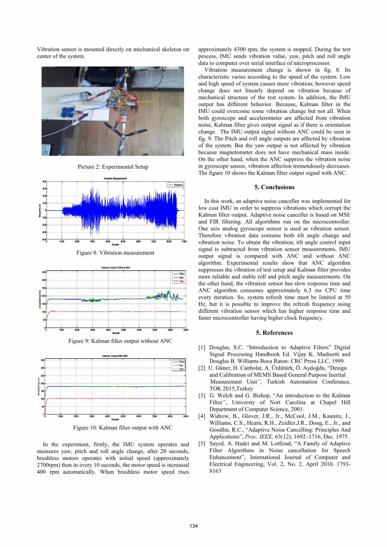
Vibration measurement change is shown in fig. 8. Its
characteristic varies according to the speed of the system. Low
and high speed of system causes more vibration; however speed
change does not linearly depend on vibration because of
mechanical structure of the test system. In addition, the IMU
output has different behavior. Because, Kalman filter in the
IMU could overcome some vibration change but not all. When
both gyroscope and accelerometer are affected from vibration
noise, Kalman filter gives output signal as if there is orientation
change. The IMU output signal without ANC could be seen in
fig. 9. The Pitch and roll angle outputs are affected by vibration
of the system. But the yaw output is not affected by vibration
because magnetometer does not have mechanical mass inside.
On the other hand, when the ANC suppress the vibration noise
in gyroscope sensor, vibration affection tremendously decreases.
The figure 10 shows the Kalman filter output signal with ANC.
5. Conclusions
In this work, an adaptive noise canceller was implemented for
low cost IMU in order to suppress vibrations which corrupt the
Kalman filter output. Adaptive noise canceller is based on MSE
and FIR filtering. All algorithms run on the microcontroller.
One axis analog gyroscope sensor is used as vibration sensor.
Therefore vibration data contains both tilt angle change and
vibration noise. To obtain the vibration, tilt angle control input
signal is subtracted from vibration sensor measurements. IMU
output signal is compared with ANC and without ANC
algorithm. Experimental results show that ANC algorithm
suppresses the vibration of test setup and Kalman filter provides
more reliable and stable roll and pitch angle measurements. On
the other hand, the vibration sensor has slow response time and
ANC algorithm consumes approximately 6.3 ms CPU time
every iteration. So, system refresh time must be limited at 50
Hz, but it is possible to improve the refresh frequency using
different vibration sensor which has higher response time and
faster microcontroller having higher clock frequency.
5. References
[1] Douglas, S.C. “Introduction to Adaptive Filters” Digital
Signal Processing Handbook Ed. Vijay K. Madisetti and
Douglas B. Williams Boca Raton: CRC Press LLC, 1999
[2] U. Güner, H. Canbolat, A. Ünlütürk, Ö. Aydoğdu, “Design
and Calibration of MEMS Based General Purpose Inertial
Measurement Unit”, Turkish Automation Conferance,
TOK 2015,Turkey
[3] G. Welch and G. Bishop, “An introduction to the Kalman
Filter”, Universty of Nort Carolina at Chapel Hill
Department of Computer Science, 2001.
[4] Widrow, B., Glover, J.R., Jr., McCool, J.M., Kaunitz, J.,
Williams, C.S., Hearn, R.H., Zeidler,J.R., Dong, E., Jr., and
Goodlin, R.C., “Adaptive Noise Cancelling: Principles And
Applications”, Proc. IEEE, 63(12), 1692–1716, Dec. 1975.
[5] Sayed. A. Hadei and M. Lotfizad, “A Family of Adaptive
Filter Algorithms in Noise cancellation for Speech
Enhancement”, International Journal of Computer and
Electrical Engineering, Vol. 2, No. 2, April 2010. 1793-
8163
Figure 10: Kalman filter output with ANC
Figure 8: Vibration measurement
Figure 9: Kalman filter output without ANC
134