Embed Size (px)
Citation preview
DESIGN AND IMPLEMENTATION OF AN AUTONOMOUS
FIRE FIGHTING ROBOT
A Thesis
Presented to
The Faculty of Graduate Studies
of
The University of Guelph
by
DILIP PARMAR
In partial fulfillment of requirements
for the degree of
Master of Science
April 2011
copy Dilip Parmar 2011
11 Library and Archives Canada
Published Heritage Branch
395 Wellington Street OttawaONK1A0N4 Canada
Bibliotheque et Archives Canada
Direction du Patrimoine de Iedition
395 rue Wellington OttawaONK1A0N4 Canada
Your file Votre reference ISBN 978-0-494-80013-3 Our file Notre r6f6rence ISBN 978-0-494-80013-3
NOTICE
The author has granted a nonshyexclusive license allowing Library and Archives Canada to reproduce publish archive preserve conserve communicate to the public by telecommunication or on the Internet loan distribute and sell theses worldwide for commercial or nonshycommercial purposes in microform paper electronic andor any other formats
The author retains copyright ownership and moral rights in this thesis Neither the thesis nor substantial extracts from it may be printed or otherwise reproduced without the authors permission
AVIS
Lauteur a accorde une licence non exclusive permettant a la Bibliotheque et Archives Canada de reproduce publier archiver sauvegarder conserver transmettre au public par telecommunication ou par Ilnternet preter distribuer et vendre des theses partout dans le monde a des fins commerciales ou autres sur support microforme papier electronique etou autres formats
Lauteur conserve la propriete du droit dauteur et des droits moraux qui protege cette these Ni la these ni des extraits substantiels de celle-ci ne doivent etre imprimes ou autrement reproduits sans son autorisation
In compliance with the Canadian Privacy Act some supporting forms may have been removed from this thesis
While these forms may be included in the document page count their removal does not represent any loss of content from the thesis
Conformement a la loi canadienne sur la protection de la vie privee quelques formulaires secondaires ont ete enleves de cette these
Bien que ces formulaires aient inclus dans la pagination il ny aura aucun contenu manquant
1+1
Canada
ABSTRACT
DESIGN AND IMPLEMENTATION OF AN AUTONOMOUS FIRE FIGHTING ROBOT
Dilip Parmar Advisor University of Guelph 2011 Professor Simon X Yang
The concept of engineering robots has become increasingly popular in last decades
Industrial and commercial businesses that can afford the cost of robotic systems have
introduced them into their manufacturing processes These technologies are not popular
at the consumer level since it can become costly
In this thesis a fire fighting robot is designed and compared with others that have
been created By combining different technologies we can create a robotic system that
would detect a flame and extinguish it before it becomes disastrous The requirements
of such technology would require the robot to navigate through its environment find
the flame and safely extinguish it A mobile robot with these characteristics involves
many different disciplines
There are four main systems that create this robot mobility obstacle avoidance
flame detection and flame extinguishing Mobility consists of motor control though
programmable logic and circuit integration Obstacle avoidance is designed through the
relations between echo pulses and timing Flame detection uses a novel search method
based on algorithms for patterns of a flame Lastly the flame extinguisher uses the
same system as a fire extinguisher would except it uses water as a source Analysis and
design of fuzzy control laws are implemented to create the robots behaviours Using
these systems we can create a low cost robot that would help to bring technologies
home
Dedication
To my family and friends
Acknowledgment
I would like to thank my advisor Dr Simon Yang in helping me to pursue my graduate
studies and research in the field of Engineering I want to express my sincere gratitude
for all the guidance and support he has given me
I would like to thank Dr Fantahun Defersha for being part of my advisory commitshy
tee and providing valuable suggestions and advice I appreciate Dr Stefano Gregori for
being the chair for my defence and for his suggestions and advice
I would like to thank my family for allowing me to continue my studies Special
thanks to my sister who has contributed so much over the years and her contribution to
this thesis Without all their support I could not have finished this thesis
n
Contents
List of Tables vi
List of Figures vii
List of Symbols x
1 Introduction 1
11 Statement of Problems 4
12 Objective of this Thesis 5
13 The Proposed Method 6
14 Contributions of this Thesis 7
15 Organization of this Thesis 8
2 Background 10
21 Autonomous Robot Navigation 12
22 Sensors 13
221 Obstacle Detection 13
222 Flame Detection 14
23 Behaviour-Based Control 15
24 Fuzzy Control 16
241 Fuzzy Sets and Membership Functions 17
242 Fuzzy Logic Control 18
3 Literature Survey 20
31 Fire Fighting Robots 20
32 Sensor Fusion 24
321 Ultrasonic Sensors 24
iii
322 Flame Sensors 29
33 Fuzzy Control 30
4 The Developed Fire Fighting Robot System 33
41 Introduction 33
42 Mechanical Design 35
421 Motor Design 35
422 Sensor Design 39
423 Flame Retardant 43
424 Control System 44
425 Power Supply 47
43 The Kinematics of the Robot 47
44 Implementation 49
45 Summary 51
5 Obstacle Avoidance Using Fuzzy Logic 52
51 Introduction 52
52 The Concept of Ultrasonic Sensors 55
53 Fuzzy Control for Obstacle Avoidance 56
531 Fuzzification 57
532 Inference Mechanism 58
533 Defuzzification 62
54 Experiments 63
55 Summary 65
6 Target Approaching using Sensor Fusion and Fuzzy Logic 67
61 Introduction 68
62 Design of a CdS Photocell Sensor 69
63 Sensor Placement and Detection 70
64 Fuzzy Control for Target Approaching 73
65 Experiments 78
66 Summary 79
iv
7 A Novel Approach for Extinguishing a Flame 80
71 Introduction 81
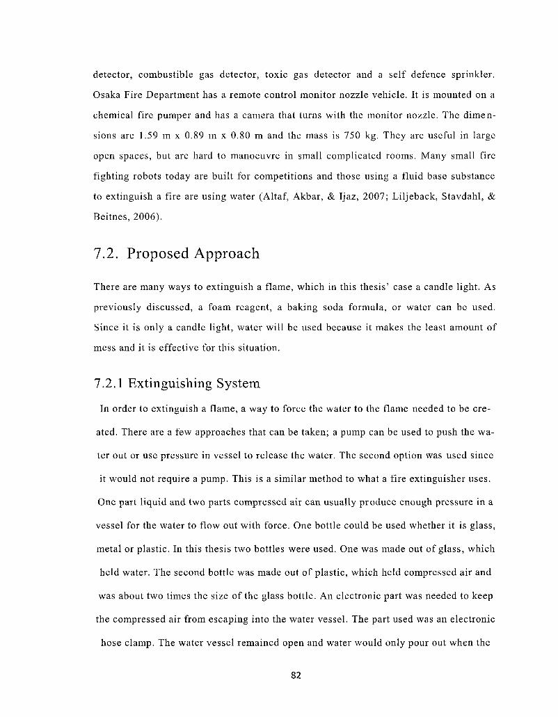
72 Proposed Approach 82
721 Extinguishing System 82
722 Fuzzy Control and System Design 84
73 Experiments 87
74 Summary 89
8 Experimental Results 90
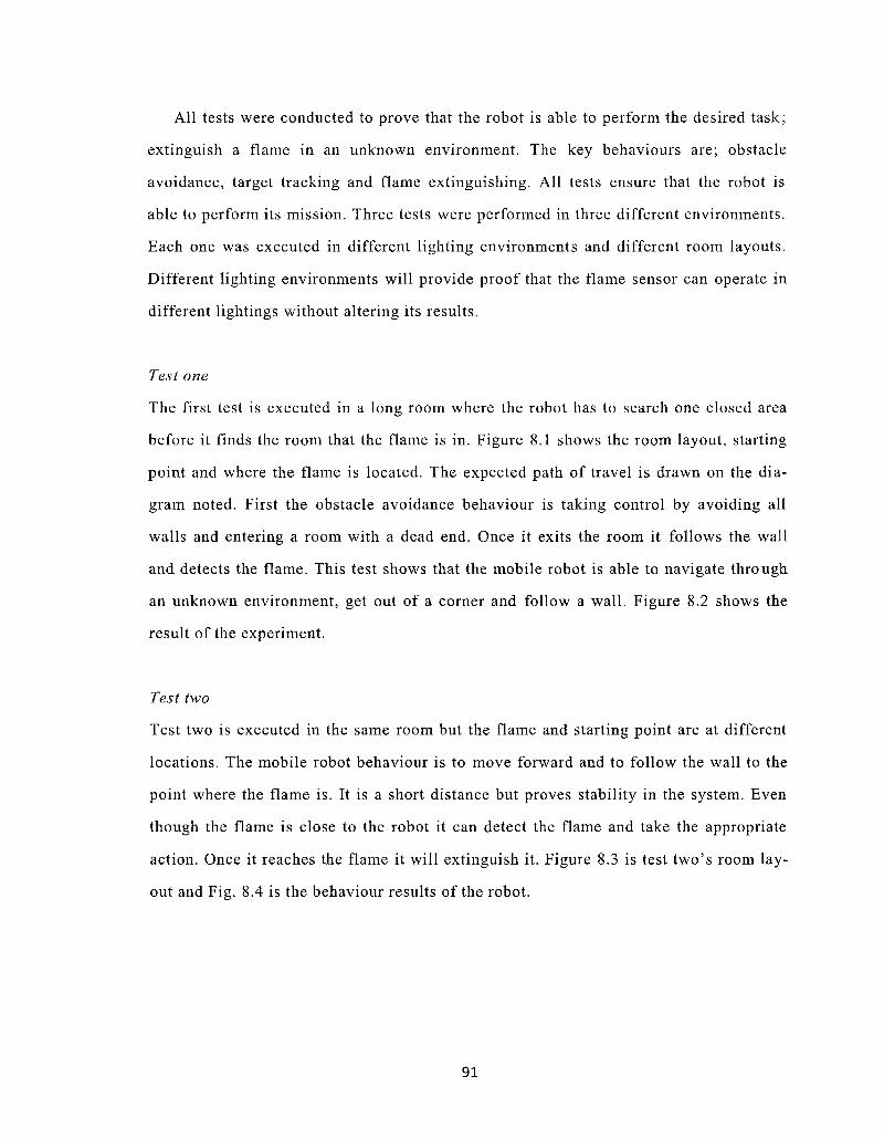
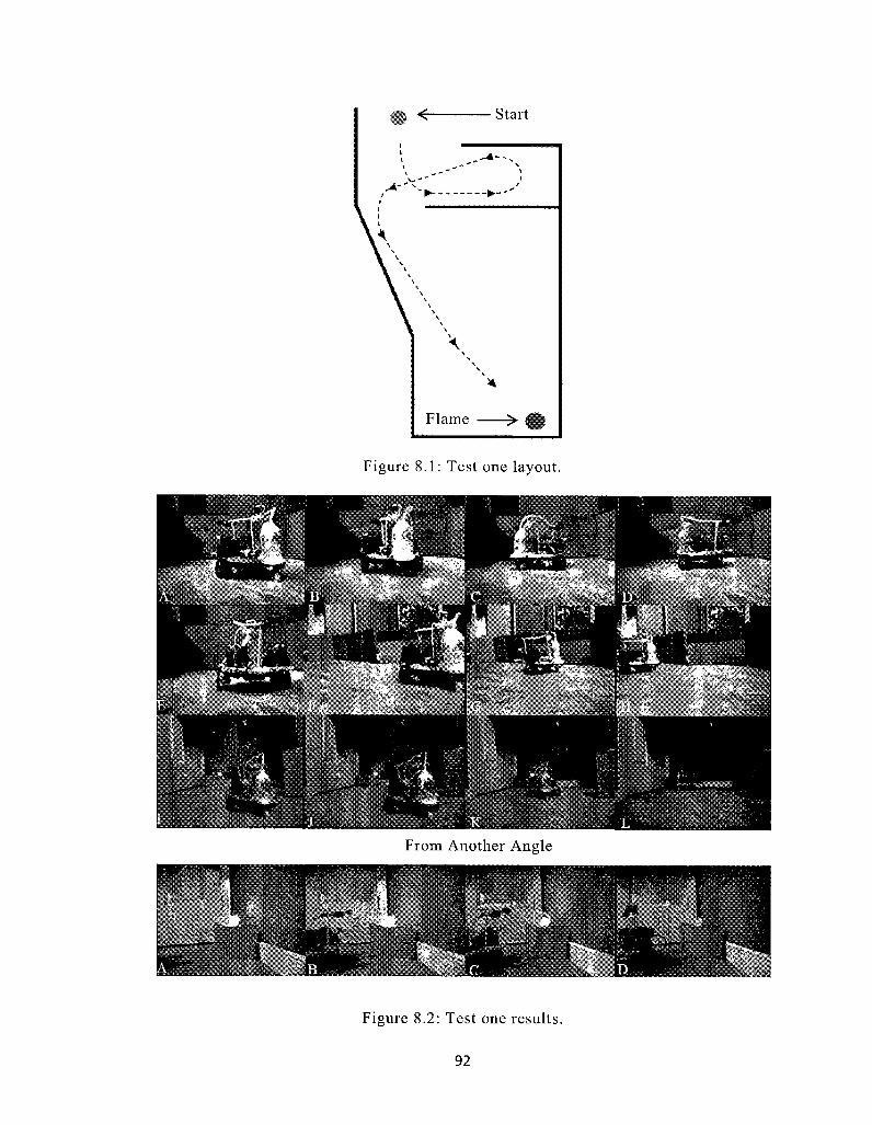
81 Fire Fighting Experiments 90
82 Summary 95
9 Discussions 96
91 Safety 96
92 Reliability 97
93 Commercialization 98
10 Conclusion and Future Work 100
101 Conclusions 100
102 Future Work 102
References 103
Appendix A The Control Program for the Fire Fighting Robot 111
v
List of Tables
41 Distances versus time in milliseconds (Dean 2001) 42
51 Typical values for sensor (Parallax INC 2009) 56
52 Rules for ultrasonic sensors 59
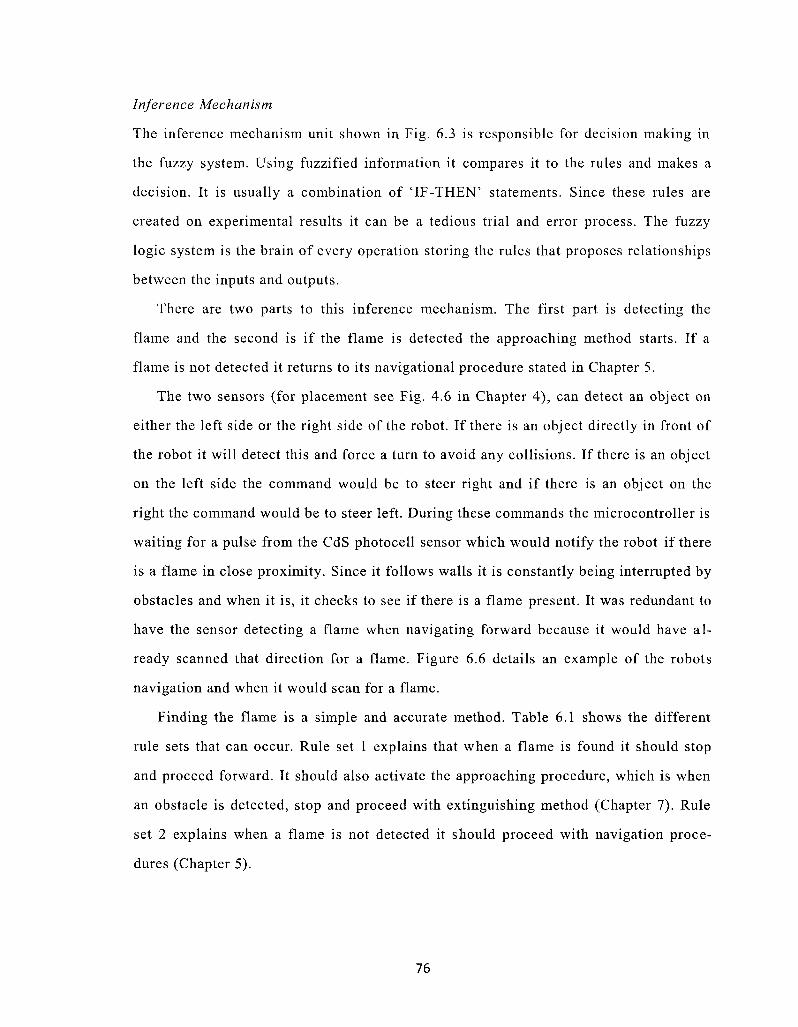
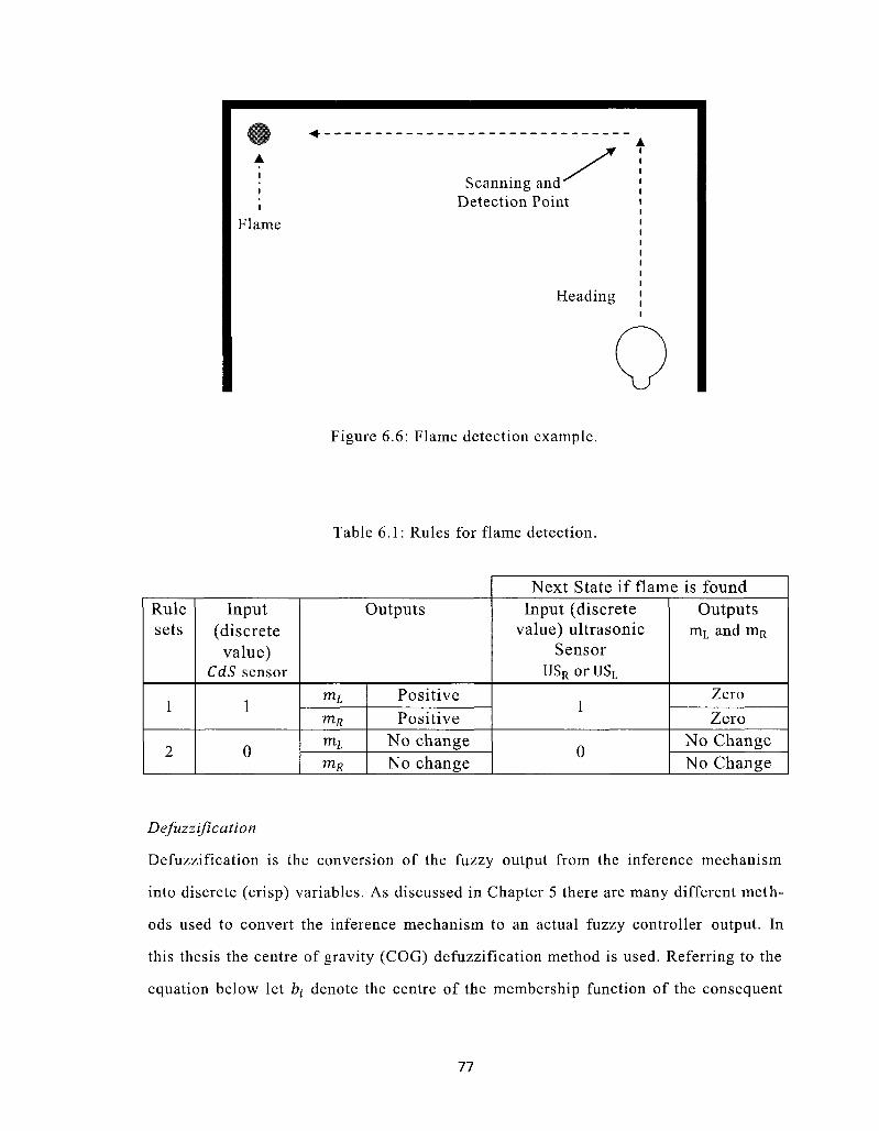
61 Rules for flame detection 77
71 Rules for extinguishing a flame 86
91 Robot cost evaluation 98
VI
List of Figures
21 Basic fuzzy control system 18
31 Florida International Universitys robot (from Dubel et al 2003) 22
32 Large Fire Fighting Robot (from Parekh 2006) 22
33 First INtelligent Extinguisher (Fine) (from Rajni 2009) 23
34 Location of the ultrasonic sensors (from Le et al 2007) 25
35 Movement of robot in 3 different instances (from Le et al 2007) 26
36 Detecting experimental board (from Luo et al 2007) 26
37 Vertical plane used for testing (a) and the exploration results of the vertishy
cal plane (b) (from Luo et al 2007) 27
38 Cambered surface used for testing (a) and exploration results of cambered
surface (b) (from Luo et al 2007) 28
39 UV Trons spectral response and various light source (from Hamamatsu
1998) 30
310 Architecture block diagram (from Abreu amp Correia 2001) 32
41 The designed fire fighting robot 34
42 AutoCAD render of the base of the robot 36
43 Tires and motors (from RobotShop 2009) 37
44 H-Bridge designed by Bolt (from Seale 2003) 38
45 AutoCAD caster wheel drawings (top and side view) 39
46 Sensor placement on the robot 40
47 Ultrasonic sensing path (from Parallax INC 2009) 40
vii
48 Sensing angle for the robot 41
49 Ultrasonic sensor 42
410 CdS photocell sensor 43
411 The schematic of the control design 45
412 Control boards for the fire fighting robot 45
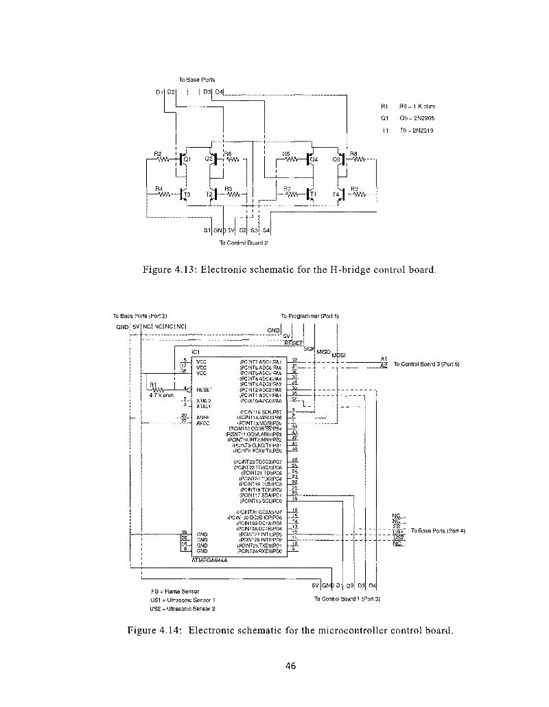
413 Electronic schematic for the H-bridge control board 46
414 Electronic schematic for the microcontroller control board 46
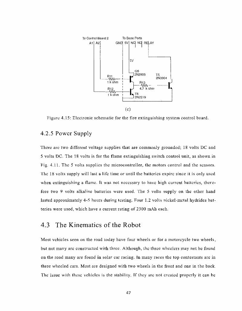
415 Electronic schematic for the fire extinguishing system control board 47
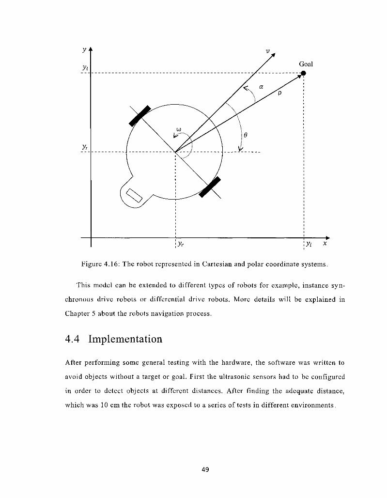
416 The robot represented in Cartesian and polar coordinate systems 49
51 Signals from the ultrasonic sensor (from Parallax INC 2019) 56
52 Block diagram of the fuzzy controller 57
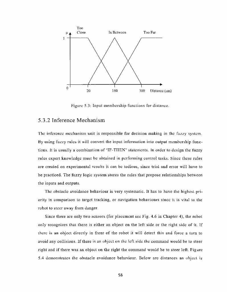
53 Input membership functions for distance 58
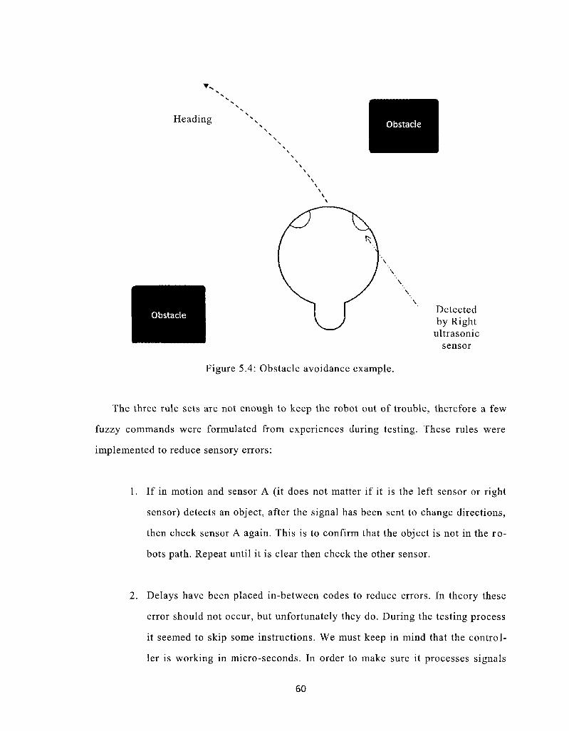
54 Obstacle avoidance example 60
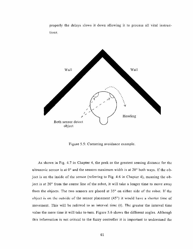
55 Cornering avoidance example 61
56 Angles and sensory placement for the robot 62
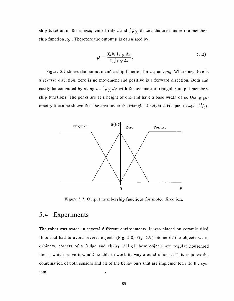
57 Output membership functions for motor direction 63
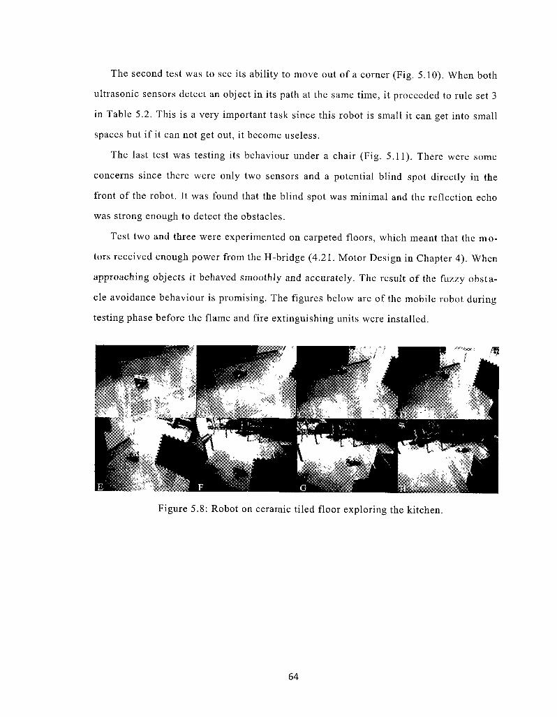
58 Robot on ceramic tiled floor exploring the kitchen 64
59 Robot on ceramic tiled floor steering its way through a corridor 65
510 Robot on carpet floor getting out of a corner 65
511 Robot on carpet floor steering its way under a chair 65
61 Circuitry of CdS photocell sensor 70
62 Placement of sensors 72
63 Sensor fuzzy controller block diagram 74
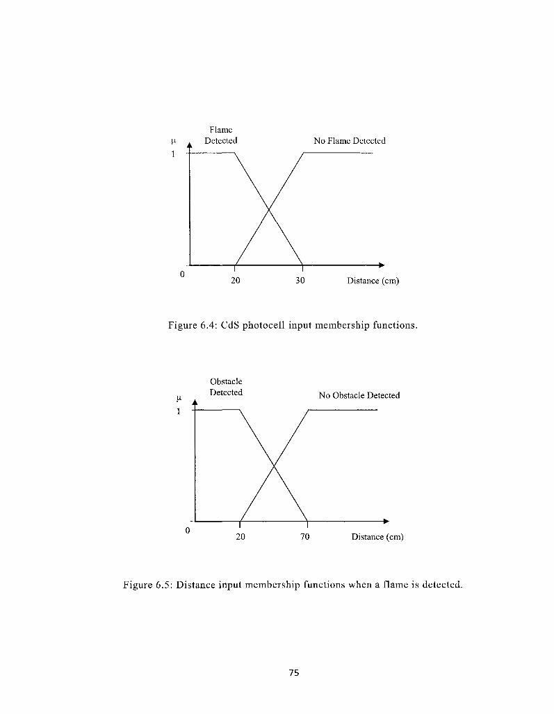
64 CdS photocell input membership functions 75
65 Distance input membership functions when a flame is detected 75
66 Flame detection example 77
67 Output membership functions for the motor direction 78
viii
71 Water and air vessel set-up 83
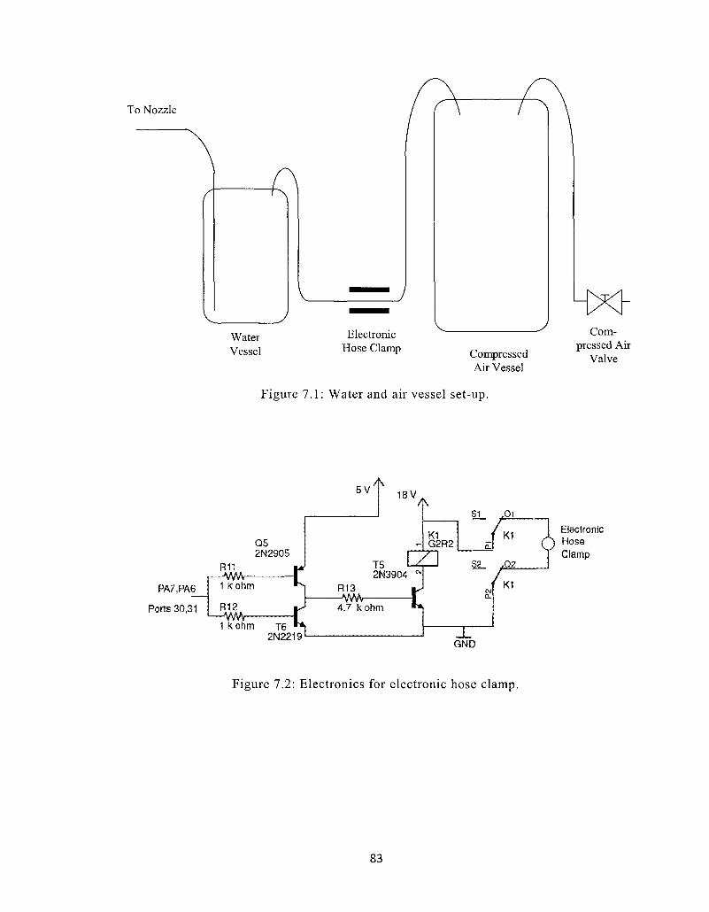
72 Electronics for electronic hose clamp 83
73 Electronic hose clamp and main power switch 84
74 Fuzzy controller block diagram for the fire fighting robot 85
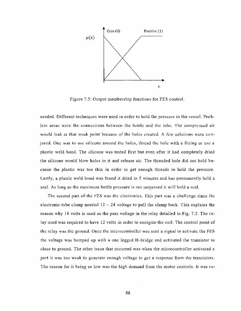
75 Output membership functions for the FES control 88
81 Test one layout 92
82 Test one results 92
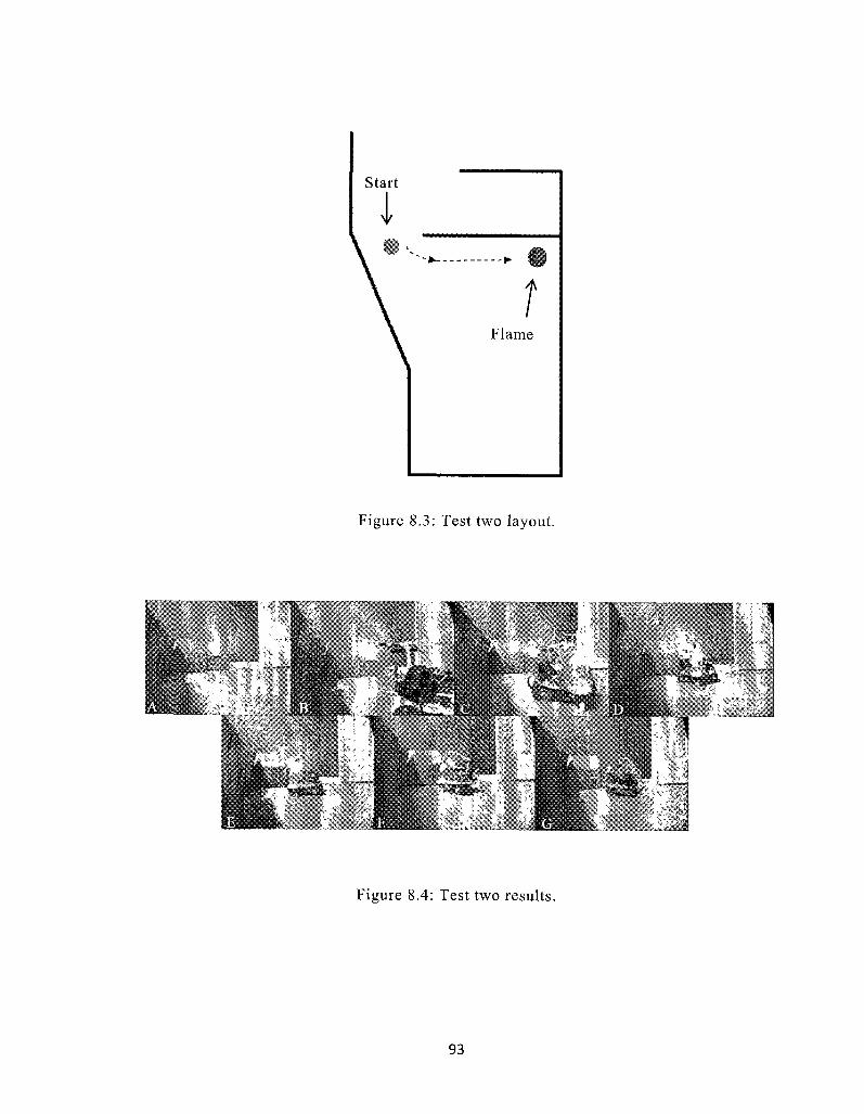
83 Test two layout 93
84 Test two results 93
85 Test three layout 94
86 Test three results 94
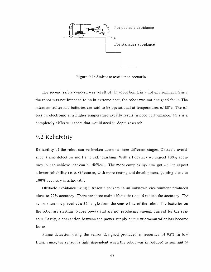
91 Staircase avoidance scenario 97
IX
List of Symbols
a Acceleration of robot
C(T) Speed of sound in air as a function of temperature
F Force
FES Fire Extinguishing Unit
IB For ultrasonic membership it represents in between
m Mass
mL Left motor
mR Right motor
r Radius of tires
T Temperature in degC
T The motor torque
TC For ultrasonic membership it represents too close
TF For ultrasonic membership it represents too far
S Sensor distance from object
USi Left ultrasonic sensor
USR Right ultrasonic sensor
v Velocity of robot
a Angle between goal and direction
x Crisp value
co The steering angle with respect to the vehicle body
p Direction to goal
6 The angle of the vehicle body with respect to the horizontal line
Chapter 1
Introduction
Robots are being used everywhere to maximize efficiency safety and entertainment
A robot is typically a machine or device that autonomously completes tasks Some inshy
dustries that use a wide range of well developed robots are hospitals manufacturing
businesses and the military Hospitals and manufacturing businesses favour robots that
are stationary which are defined by the line of work It has been proven that robots inshy
crease production and accuracies that a human can not achieve The military is eagerly
interested in robots that are mobile With mobile technologies it can be assumed that
complexities will increase Complexities appear because of unknown environments and
the constant change in environments which is found in the real world
With the vast number of robots being built and experimented with we are able to deshy
sign robots that are reliable and cost efficient Using different disciplines such as meshy
chanical and electrical engineering an autonomous mobile robot can be designed Adshy
vancements in technologies can make dangerous jobs become easier and safer Mobile
robots have been known to carry out human-like operations in hazardous situations
such as nuclear plants or bomb elimination (Wang 2004)
These machines can be called intelligent but first we must learn to mimic our acshy
tions so we can implement them into a system The intelligent system evolves by using
behaviour-based approaches such as a goal Goals can become a physical action by usshy
ing the sensor data and manipulation of codes to affect its surrounding environments
1
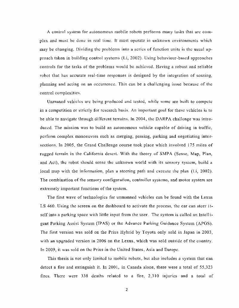
A control system for autonomous mobile robots performs many tasks that are comshy
plex and must be done in real time It must operate in unknown environments which
may be changing Dividing the problems into a series of function units is the usual apshy
proach taken in building control systems (Li 2002) Using behaviour-based approaches
controls for the tasks of the problems would be achieved Having a robust and reliable
robot that has accurate real-time responses is designed by the integration of sensing
planning and acting on an occurrence This can be a challenging issue because of the
control complexities
Unmaned vehicles are being produced and tested while some are built to compete
in a competition or strictly for research basis An important goal for these vehicles is to
be able to navigate through different terrains In 2004 the DARPA challenge was introshy
duced The mission was to build an autonomous vehicle capable of driving in traffic
perform complex manoeuvres such as merging passing parking and negotiating intershy
sections In 2005 the Grand Challenge course took place which involved 175 miles of
rugged terrain in the California desert With the theory of SMPA (Sense Map Plan
and Act) the robot should sense the unknown world with its sensory system build a
local map with the information plan a steering path and execute the plan (Li 2002)
The combination of the sensory configuration controller systems and motor system are
extremely important functions of the system
The first wave of technologies for unmanned vehicles can be found with the Lexus
LS 460 Using the screen on the dashboard to activate the process the car can steer itshy
self into a parking space with little input from the user The system is called an Intellishy
gent Parking Assist System (IPAS) or the Advance Parking Guidance System (APGS)
The first version was sold on the Prius Hybrid by Toyota only sold in Japan in 2003
with an upgraded version in 2006 on the Lexus which was sold outside of the country
In 2009 it was sold on the Prius in the United States Asia and Europe
This thesis is not only limited to mobile robots but also includes a system that can
detect a fire and extinguish it In 2001 in Canada alone there were a total of 55323
fires There were 338 deaths related to a fire 2310 injuries and a total of
2
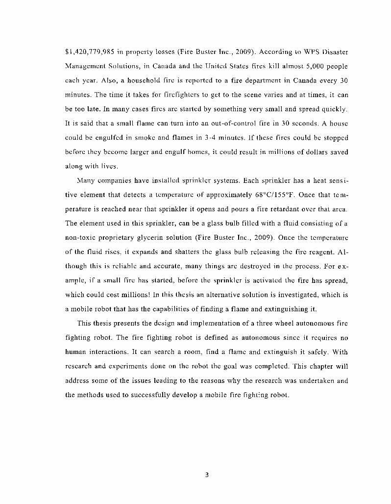
$1420779985 in property losses (Fire Buster Inc 2009) According to WPS Disaster
Management Solutions in Canada and the United States fires kill almost 5000 people
each year Also a household fire is reported to a fire department in Canada every 30
minutes The time it takes for firefighters to get to the scene varies and at times it can
be too late In many cases fires are started by something very small and spread quickly
It is said that a small flame can turn into an out-of-control fire in 30 seconds A house
could be engulfed in smoke and flames in 3-4 minutes If these fires could be stopped
before they become larger and engulf homes it could result in millions of dollars saved
along with lives
Many companies have installed sprinkler systems Each sprinkler has a heat sensishy
tive element that detects a temperature of approximately 68degC155degF Once that temshy
perature is reached near that sprinkler it opens and pours a fire retardant over that area
The element used in this sprinkler can be a glass bulb filled with a fluid consisting of a
non-toxic proprietary glycerin solution (Fire Buster Inc 2009) Once the temperature
of the fluid rises it expands and shatters the glass bulb releasing the fire reagent Alshy
though this is reliable and accurate many things are destroyed in the process For exshy
ample if a small fire has started before the sprinkler is activated the fire has spread
which could cost millions In this thesis an alternative solution is investigated which is
a mobile robot that has the capabilities of finding a flame and extinguishing it
This thesis presents the design and implementation of a three wheel autonomous fire
fighting robot The fire fighting robot is defined as autonomous since it requires no
human interactions It can search a room find a flame and extinguish it safely With
research and experiments done on the robot the goal was completed This chapter will
address some of the issues leading to the reasons why the research was undertaken and
the methods used to successfully develop a mobile fire fighting robot
3
11 Statement of the Problems
An autonomous robot is not a novel topic With the passing of time advanced technoloshy
gies have proven to be successful in providing safer working and living environments
Autonomous vehicles are a well researched area in recent years which have allowed
new technologies that allow driving tasks to be fulfilled by a computer system without
any flaws
A robot can become a complicated system when building it from scratch Although
trouble shooting can be reduced by a well thought out design Dividing the robot into
different sections will help reduce the complexity If we examine a mobile robot we can
conclude that there are three main parts the mechanical system the electrical system
and the software system The mechanical and electrical system can be weighted by a
visual aspect and can be physically grasped but the software system can only be seen
The mechanical systems are classified as the body of the robot Motors tires holdshy
ing tanks the platform of the robot screws etc are classified as the body Most of
these parts can be bought and are cheaper to buy rather than building it from scratch It
is easy to find a part such as a motor that suits your robot A few calculations can be
made in order to derive the necessary torque or acceleration needed for your robot to
move
Parts such as micro-controllers sensors or voltage regulators can be considered as
electrical systems Micro-controllers are one of the best devices to use for this type of
application They can be programmed to accomplish many different tasks but alone
they are useless Using sensors andor other electronic components integrated with a
controller you can create different devices for different purposes
Software systems are contained in the micro-controller They are lines of code that
are created using a computer and stored on the controllers memory They perform
functions programmed by the user This can be the most time consuming system to deshy
velop
4
Important factors when creating a robot is to create one that is expandable adaptshy
able and researchable It is also important that people can learn from it Robot techshy
nologies are everywhere Fully designed robots can be bought and tested but are not
researchable or expandable (Dong 2005) Therefore creating a robot with a purpose
and which have expandability will guide advancements in research and technologies
12 Objective of this Thesis
This thesis focus is on the development of a mobile robot that has the ability to detect
and extinguish a flame Designed by research in fire fighting robots and inspired by
competitions an open ended robot was designed Electrical mechanical and software
systems are discussed The mobile robot must navigate around objects and locate the
target using ultrasonic sensors and a flame detection sensor
The behaviour-based mobile robot has been engineered with hardware and software
designs described in this thesis Existing hardware is used to implement a fuzzy logic
system to allow the robot to explore the unknown environment
In order to keep the cost of the robot low developing a system with inexpensive
parts and using the least amount of parts is investigated A major cost is the ultrasonic
sensor which must be able to withstand heat and smoke Although there are many inexshy
pensive solutions for ultrasonic sensors they are not reliable in those extreme condishy
tions
The following must be fulfilled in order to measure the performance of this robot
bull The robot can explore the environment finding the specific target which
in this case is a flame
bull The robot is able to extinguish the flame safely and effectively
bull The robot can detect object or obstacles in its path and navigate around
them
5
Robot navigation though its environment avoiding objects ability to search for a
flame and extinguish a flame is acquired by using the following methods
bull Fuzzy logic is used for navigational purposes and to search for a flame
bull The Atmel architecture is used to design the system
bull A dynamic method is used to extinguish the flame
13 The Proposed Method
Flame detection and navigation can be a difficult procedure and can depend on your
hardware Atmels microcontroller with multiple sensors was used to design a fire
fighting robot The movement of the robot is behaviour-based which basically mimics
actions of a human Using human tendencies a set of fuzzy rules were designed The
controller was designed to carry out navigation tasks the flame detection task and the
flame extinguishing task
The fuzzy control system was proposed to implement the movement of the robot
Using the sensors as input the directions are calculated and decoded to the motors for
directional purposes The sensors include two ultrasonic sensors and one CdS photocell
sensor The sensors will be positioned in a way that each sensor detects an object on
one side of the robot Therefore the sensors cover a span of approximately 160deg of the
front of the robot A set of fuzzy rules was composed using behaviour-based methods
Different situations were taken into account when designing the rules such as corners
and tight spaces These are conventional methods which have proven successful over
years of research All possible events that can occur are taken into account including
potential problems such as a moving objects Since the processing is in real-time the
processing speed is extremely fast in order to nullify failures
While the robot is exploring the environment it must be able to steer around object
The ultrasonic sensors direct it away from objects and the CdS photocell sensor finds
the flame Once the flame is found it must stay a safe distance away and extinguish the
flame successfully The base of the robot must be strong enough to support the payload
6
which would include batteries the controller sensors and a fire retardant Also the moshy
tors that drive the wheels must have enough torque to move itself around Since it is a
three wheel system with two powered wheels the steering is changed by changing the
direction of the motors
14 Contributions of this Thesis
This thesis is not limited to the theoretical knowledge It also tests the applications of
the theory by implementation The contributions are summarized as follows
1 Control of the robot is manipulated by the ATmega644 micro-controller
This is an 8-bit controller with 64k bytes in-system programmable flash Usshy
ing the architecture that Atmel has provided it has proven that it is easy to
use and implement Using a programming language the system can be simushy
lated in AVR studios and then tested on hardware This is a low cost and
adequate solution
2 An obstacle avoidance method is developed with fuzzy control theory and
sensor fusion Using the extracted knowledge from the ultrasonic sensors
fuzzy set were created to navigate in a room around objects and to a target
This is important in avoiding harm to the mobile robot when it is approachshy
ing the target or moving around objects
3 A flame detection system is designed in order to guide the robot to a fire A
step to making the mobile robot autonomous is designing it to find its own
target Using a sensor and fuzzy systems it is able to pin point a flame in a
certain direction
4 A flame extinguishing method is created to eliminate the threat of a fire beshy
come larger Water and compressed air was the cheapest and a reliable solushy
tion Some fire extinguishers use water and others may use carbon dioxide
sodium bicarbonate ammonium phosphate etc
7
15 Organization of this Thesis
The design of a fire fighting mobile robot is a detailed project It requires many devices
that need an adequate control system The methodology behind tracking the target using
a CdS photocell sensor ultrasonic sensor fusion using fuzzy based rules to detect obshy
jects and a fire extinguisher system are discussed
Chapter 2 introduces the background information to this thesis The theories related
to the design of the autonomous fire fighting robot Behaviour-based design is exshy
pressed as it relates to the unknown environment Fuzzy logic algorithms are discussed
with the extracted knowledge from the distance sensors and flame sensor
Chapter 3 is a literature review of previous work in related fields Some of the preshy
sented works are studies in ultrasonic sensors movement of the mobile robot and fuzzy
systems
Chapter 4 presents the developed fire fighting robot The hardware design and softshy
ware design are discussed in this chapter The sensor fusion is discussed along with the
multi-layer architecture The mechanical system are detailed with background knowlshy
edge
Chapter 5 addresses the obstacle avoidance method Developed by a behaviour
based method the fuzzy control is explained Using multiple sensors on-board the beshy
haviour based mobile robot interacts with the real world The fuzzification inference
mechanism unit and the defuzzification method is explained The membership functions
are designed for the input and output devices The motion controls and navigational
processes are examined The stability of the robot is proven by the performance of the
accurate motions that it produces Control strategies are imbedded through programshy
ming on the discussed microcontroller
Chapter 6 discusses the target approaching application A fuzzy logic system is inshy
troduced to systematically decipher the sensors data The knowledge based system
adequately guides the mobile robot to the target to accomplish its mission A flame sen-
8
sor is created using a novel method Some experiments are performed to demonstrate
the method proposed
Chapter 7 introduces a method of extinguishing a flame The method is based on a
fire extinguisher and the proposed approach is proven to be a desirable method The
controlling circuitry is detailed with the fuzzy controls that are integrated with the other
sensor fusion which are detailed in Chapter 5 and Chapter 6 Tests are completed to
test the accuracy of the method
In Chapter 8 the experiments setup and results are discussed proving that it is a
successful mobile robot
In Chapter 9 safety reliability and commercialization issues are discussed briefly
In Chapter 10 conclusions are presented and recommendations for future work are
detailed
9
Chapter 2
Background
Autonomous robot to a certain degree can be classified as an artificial intelligence (Al)
Al is defined as to create machines designed to perform tasks that normally associate
to human intelligence such as reasoning Shortly after World War II Alan Turing was
involved in the development of computer science furthermore evolving into creating
formulations of algorithms and computations His development is said to have played a
significant role in the creation of the modern computer Al started when algorithms
were developed to imitate the step-by-step reasoning that humans often are presented
with when in certain situations Probability and economics concepts were used to proshy
vide solutions to uncertain or incomplete information which were being successfully
employed in the late 1980s and 1990s
Some of the issues that Al researchers were confronted with are the human task that
are difficult to predict or require plenty of data such as common sense knowledge
general intelligence planning learning natural language processing motion and mashy
nipulation and social intelligence
Common sense knowledge or general intelligence is difficult to reproduce since
there are so many variables The robot needs to be able to identify objects properties
relations between objects distinguishing between different situations or event or calcushy
late a cause and effect relation This section of research requires extensive knowledge
of everything that may exist in its path Planning is the process of being able to set a
10
goal and strive to achieve it There needs to be a way for the robot to visualize the fushy
ture step it must take in order to achieve its goal If it steers off its predicted action it
needs to be able to re-calculate the steps This may require multiple checks to see if the
goal has changed and what should be done to complete the task Learning or machine
learning is the ability to implement unsupervised or supervised learning Unsupervised
learning is the ability to find patterns in various inputs Supervised learning usually inshy
cludes a classification and numerical regression process Classification can be used to
determine what category something relates to Regression takes a set of numerical inshy
puts or output and attempts to discover a function that would generate the outputs from
the given information Natural language processing is the ability to read speak and unshy
derstand the language that humans speak This may be the most difficult process Reshy
searchers hope to find a way to allow a system to learn the language by using systems
that are already available such as text on the internet Motion and Manipulation is reshy
lated to behaviour-based methods for object manipulation and navigation Mapping is
becoming extremely popular since it helps the robot to know where it is and how to get
around It also eliminates the problem of the robot navigating through the same room
repeatedly Lastly social intelligence is the emotion and social skills It needs to be
able to predict the actions of others by understanding their motives This would be difshy
ficult to model since it requires many aspects such as game theory decision theory
modeling emotions and perceptual skills to detect emotions It would be of benefit if it
could model human emotions such as being polite and sensitive to humans
Al technologies are taking place in many parts of the world today Osaka University
has a realistic 4 year old girl called the Repliee Rl It has nine DC motors in its head
for movement of prosthetic eyeballs and silicone skin There is also another female roshy
bot from Japan Actroid who can respond to a few questions you ask With Al technoloshy
gies becoming more of a reality we can expect these technologies to become increasshy
ingly popular around the world
This chapter will overview the theoretical work that has been done in mobile roshy
bots sensor fusion fuzzy fusion and fire extinguishing methods While discussing the
11
fundamental theories applied in the field of robotic navigations the fuzzy and genetic
algorithms are surveyed
21 Autonomous Robot Navigation
Autonomous robotic navigation is the exploration of a robot guiding its way around obshy
ject to a destination A fully autonomous robot should have the ability to gain informashy
tion about the environment it is in and to navigate without human interaction For a
mobile robot this can be difficult in certain situations The scenario becomes complishy
cated due to the lack of knowledge of the environment and the absence of human intershy
action Great strives have been taken to improve robotic navigation with tremendous
success An important role in advancements is machine learning techniques The senshy
sors information only provides real-time information for example there is an obstacle
in the desired path Unfortunately it can find itself in a situation it was just in A chalshy
lenge could be a corner of two walls since it would want to turn right because of the
object on the left and turn left because of the object on the right If possible the best
method would be to allow the robot to learn its environment and map out each area
Other challenges include the differences between traversable objects such as plant
vegetation or nontraversable objects like rocks and trees (Bagnell Bradley Silver
Sofman amp Stenta 2010) Many approaches have been designed and implemented sucshy
cessfully to overcome come challenges
This autonomous robot uses reactive navigation which can be defined as gathering
information at that moment and making action on that instance (Wang 2004) This
method is much quicker than any other method Usually movement commands are creshy
ated to react to sensory data It is similar to an open loop system instead of a closed
loop system that would compare the last steps it took The robot would have no knowlshy
edge of where it is or where it was The robot simply acts on the changing environments
of the world and modifies the step to the scenarios (Putney 2006) Comparing it to de-
12
liberative navigation which uses a sensing planning and tracking method it reduces
the time it takes to process
22 Sensors
There are many different types of sensors where all have different applications Sensors
can be either electronic or physical devices that show a reading just like a mercury
filled thermometer A senor is a device that receives a signal and responds by using a
signal or a physical displacement Some sensors that are found everyday are touch-
sensitive buttons temperature sensors light sensors or water purity sensors
Most sensors are designed in a linear function using a simple mathematical funcshy
tion such as logarithmic (Ho Robinson Miller amp Davis 2005) Sensors originally
were mechanical but as they evolved they were replaced by electronic devices The
disadvantages with mechanical sensors were the adaptivity to electronic systems and
the inaccuracies that some mechanical devices can produce
221 Obstacle Detection
Range sensors are used by calculating the distance by the information given to and from
an object There are many different options available to calculate distance some types
include infrared laser range finder ultrasonic and visual cameras Infrared sensors
send out a beam of light and the distance can be calculated by using the reflected sigshy
nal The difference is distinguished by the intensity of the reflected signal They are
extremely compact inexpensive and have a detection range of 4 to 100 centimetres
which is decent for small projects Since it is light transmitted it can cause problems
with different environments that could contain smoke from a fire Radar and ultrasonic
sensors are very similar Ultrasonic sensors send out a burst of a radio frequency waves
instead of a light beam The time it takes to receive the reflection wave is used to calcushy
late the distance The ultrasonic sensors range is from 2 to 300 centimetres with a cone
shaped sensing path of 40deg This is relatively decent for a medium size project The ra-
13
dar sensor has a range of 200 to 15000 centimetres These units are usually found on
larger robots and are large and expensive It would be over-engineered for this project
Laser range finders can detect across large distances and are extremely accurate and
vary in sizes They can be found in hospital instruments or architectural designs The
down side to using these devices is that they are extremely expensive More attention
has been given to visual sensors because of their capabilities They can serve more than
one purpose such as gathering information of the environment as a whole instead of
one point They are able to detect different colours and intensities of different colours
However it would indefinitely increase the complexities and costs
222 Flame Detection
Flame detection is another type of sensor that outputs a signal when it detects a flame
There are several options depending on how sensitive you want the sensor to be There
are light detectors such as cadmium-sulfide (CdS) photocells and infrared sensors or
ultraviolet (UV) sensors that are effective at detecting flames There are more expenshy
sive options such as video flame detection or using a combination of different sensors
All of them have their benefits and disadvantages Infrared LED detectors can be
used to sense a source of light It registers as a variable resistance as the intensity of
the light become great the resistance across the LED decreases Therefore using difshy
ferent techniques such as placing a resister in series with it it can detect the intensity
of the light by using the voltage as an output The sensitivity can be adjusted by using
different resistor sizes By using a filter for direction purposes and tweaking the resisshy
tance you can easily allow it to detect a flame from a certain distance CdS photocells
are designed the same way as Infrared LED detectors except they are naturally more
sensitive to light CdS photocells are almost exposed to the environment excluding the
clear coating that is applied on top The Infrared LED is contained in a hard plastic
shell
Some UV sensors are said to be able to detect a flame in a sunny room without
fault This is amazing since sunlight is a common source of ultraviolet light The sen-
14
sor is contained by two parts a bulb and a detector circuit The bulb detects UV radiashy
tion in the 185 - 260 nm range Sunlight spectral response is just above that With their
detector circuit you are able to get either a 5 volt signal when there is a flame or a
ground signal where there is not This signal can also be inverted by using a different
port The driver circuit consumes a low current and can either use a 5 volt supply or a
10 - 30 volt supply This does increase the price marginally and if an industrial grade
sensor is needed it can be expected to increase greatly
Video flame detection would be the most expensive choice but is the perfect deshy
vice It uses a colour video imaging directly from a specially designed detection camshy
era It promises no false alarms that may occur with hot work hot C 0 2 emissions and
flare reflections It is able to work in extreme temperature conditions There are still
many other options for flame detection but these are the main devices that many use on
the market today
23 Behaviour-Based Control
Behaviour-based control is a system that was designed in the 1980s and has been
working for many years The advantage of using behaviour-based control is that it is
easy to design and implement It can be classified as a reactive control method since it
performs its objective by using sensory inputs or other input means This method shows
biological appearing actions rather than computing intensive methods This control
method supports intelligent behaviours since it forces the connections between percepshy
tions to an action Autonomous mobile robots perform many complex tasks in real time
which require quick responses Behaviour-based control can provide that with its reshy
duced computational methods It has shorter delays between gathering information and
acting on it Some of the goals it can attain are obstacle avoidance wall following
andor target tracking
The best approach for designing a control system using behaviour-based control is
to divide the system into section which can be described as tasks This will allow the
15
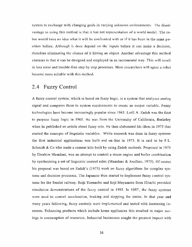
system to exchange with changing goals in varying unknown environments The disadshy
vantage to using this method is that it has not representation of a world model The roshy
bot would have no idea what it will be confronted with or if it has been in the same poshy
sition before Although it does depend on the inputs before it can make a decision
therefore eliminating the chance of it hitting an object Another advantage this method
contains is that it can be designed and employed in an incremental way This will result
in less error and trouble-free step by step processes Most researchers will agree a robot
become more reliable with this method
24 Fuzzy Control
A fuzzy control system which is based on fuzzy logic is a system that analyzes analog
signal and compares them to system requirements to create an output variable Fuzzy
technologies have become increasingly popular since 1965 Lotfi A Zadeh was the first
to purpose fuzzy logic in 1965 He was from the University of California Berkeley
when he published an article about fuzzy sets He then elaborated his ideas in 1973 that
started the concepts of linguistic variables While research was done in fuzzy systems
the first industrial applications was built and on-line in 1975 It is said to be FL
Schmidt amp Co who made a cement kiln built by using Zadeh methods Proposed in 1975
by Ebrahim Mamdani was an attempt to control a steam engine and boiler combination
by synthesizing a set of linguistic control rules (Mamdani amp Assilian 1975) Of course
his proposal was based on Zadehs (1973) work on fuzzy algorithms for complex sysshy
tems and decision processes The Japanese then started to implement fuzzy control sysshy
tems for the Sendai railway Seiji Yasunobu and Soji Muyamoto from Hitachi provided
simulation demonstrations of the fuzzy control in 1985 In 1987 the fuzzy systems
were used to control acceleration braking and stopping for trains In that year and
many years following fuzzy controls were implemented and tested with increasing inshy
terests Enhancing products which include home appliances this resulted in major savshy
ings in consumption of resources Industrial businesses sought the greatest impact with
16
machinery control processing control and intelligent sensory Today we see these sysshy
tems everywhere in industrial application and consumer levels It reduces the cost and
improved the quality of the systems but it did not just happen overnight
241 Fuzzy Sets and Membership Functions
What are fuzzy sets and membership functions Input variables that are sent through the
system are generally mapped using membership functions into fuzzy sets Therefore a
fuzzy set has a degree of membership This can be better explained in definitions by
Zadeh
Let X be objects or space of points with an element of x Thus X=x If a fuzzy
set A in X is characterized using a membership function fA(x) and X is a real number
representing the interval [01] Then its membership function can only take two values
0 and 1 fAx) = l o r O ) Therefore X either belongs to A or does not belong to A
(Zadeh 1965)
Example Let A be a fuzzy set of number much greater than 1 and Let X be all real
numbers So some values can be represented as the following fA(0) = 0 fA(l) = 0
pound ( 5 ) = 025 pound ( 2 5 ) = 125
Although the membership function resembles a probability function there are difshy
ferences between these concepts which become clearer when the rules of combination
of membership functions have been established Other definitions commonly found inshy
volving fuzzy sets are listed below
The complement of a fuzzy set A is denoted by A and is defined as
ampbull = - amp (2-1)
Containments can play important roles in fuzzy sets As they do in many other
fields A is contained in B or A is a subset of B if and only if fA = fB A^B~fA^fB (22)
The union of two fuzzy sets A and B is a fuzzy set of C whose membership funcshy
tion is related to those of A and B C = AVB (23)
c(x) = max[fA(x)fBx)lx 6 X (24)
17
Using different fuzzy set to achieving different goals are endless Many articles
have been written in depth describing different rules and manipulating them to achieve
newer models Nevertheless fuzzy system is easy to grasp making it the reason why
they are so popular
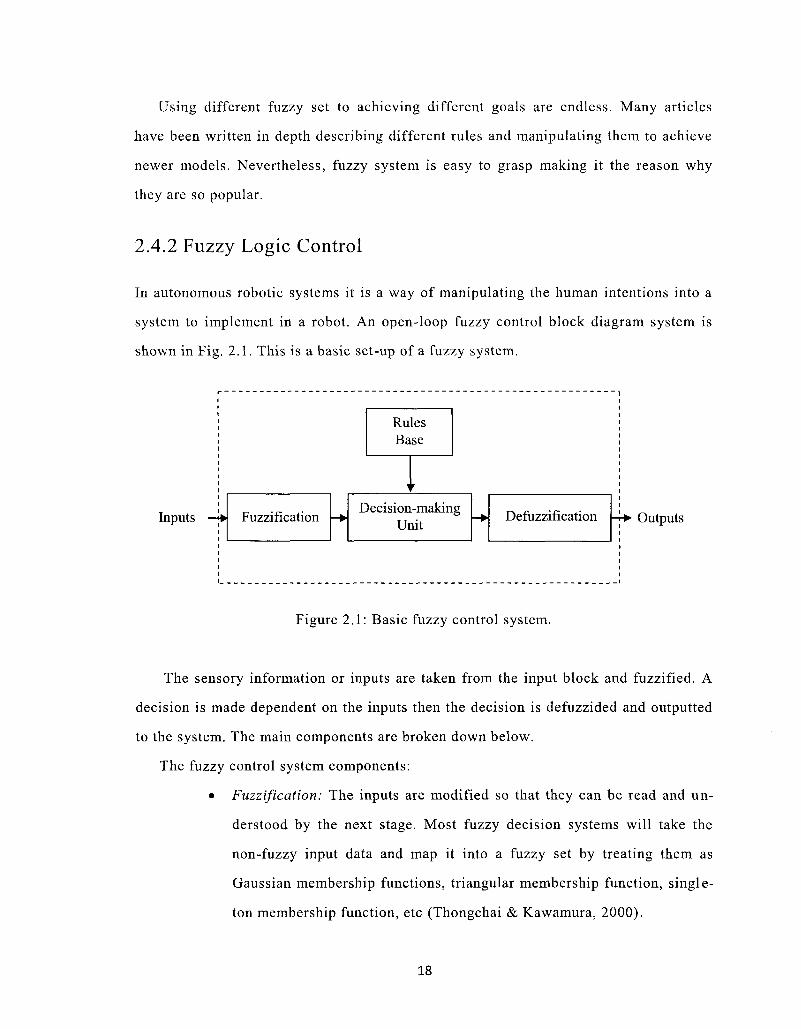
242 Fuzzy Logic Control
In autonomous robotic systems it is a way of manipulating the human intentions into a
system to implement in a robot An open-loop fuzzy control block diagram system is
shown in Fig 21 This is a basic set-up of a fuzzy system
Rules Base
Inputs Fuzzification Decision-making
Unit Defuzzification Outputs
Figure 21 Basic fuzzy control system
The sensory information or inputs are taken from the input block and fuzzified A
decision is made dependent on the inputs then the decision is defuzzided and outputted
to the system The main components are broken down below
The fuzzy control system components
bull Fuzzification The inputs are modified so that they can be read and unshy
derstood by the next stage Most fuzzy decision systems will take the
non-fuzzy input data and map it into a fuzzy set by treating them as
Gaussian membership functions triangular membership function singleshy
ton membership function etc (Thongchai amp Kawamura 2000)
18
bull Rule base the set of rules for all anticipated input variations Usually
consist of IF-THEN statements
bull Decision-making unit It compares the modified inputs with the rules and
evaluates what the outputs should be
bull Defuzzification To convert the new procedures into understandable outshy
puts for the system Some methods are Center of Gravity defuzzification
Center-Average defuzzification maximum defuzzification etc
To design a fuzzy control the rule base suggests all anticipated input variations A
designer must gather information about how the system should react to each scenario
Most of the time the information comes from human decision making in other words
imitating human actions Once a set of rules are defined they are digitized and stored
into the systems memory
19
Chapter 3
Literature Survey
Artificial Intelligence is becoming an extremely popular topic in todays research Esshy
pecially in autonomous mobile robots and androids We have already seen a wave of
these technologies implemented around the world and in space For example NASA
(National Aeronautics and Space Administration) has sent many probing units to mars
gathering information from the planet NASA stated in early 2010 that they will be
launching the first human-like robot to space It is going to become a permanent resishy
dent of the International Space Station Its name is Robonaut 2 (R2) developed with the
help of General Motors (GM) GMs interests are not only to see it in the International
Space Station but for future deployment on Earth working side-by-side with GM workshy
ers (NASA 2010) In this chapter previous research related to this thesis are reviewed
Some of the areas discussed are sensor fusion fuzzy systems and behaviour-based roshy
bots
31 Fire Fighting Robot
There are many different types of fire fighting robots such as ones that can put out car
fires or ones that are made for travel in the forest to defeat forest fires There are many
that are made for competition too which can be unfortunate since their designers do not
want to share their ideas Currently there is a Trinity College contest that is held every
year In order to win the contest you must have a robot that will move through a maze
20
find a lit candle and extinguish it It is held every year in April at Trinity College in
Hartford Connecticut USA We can split the robots into two different categories fire
fighting robots for commercial or industrial use and fire fighting robots for competition
use The more accuracy the design desires the more it will cost A robot could cost a
couple hundred dollars or it could cost a couple thousand dollars
First let us take a look at previously designed fire fighting robots used in competishy
tions Usually for competitions they have to meet a certain standard Most Universities
that participate put in $10000 for parts
Florida International University created a robot using four ultrasonic sensors that
were integrated into the system with a microcontroller to interpret the data The microshy
controller also had to interpret infrared line trackers and a camera In order to use the
ultrasonic sensor a start pulse is needs to be initiated followed by holding the line high
(1) until an echo was received The length at which the line was held high (1) relates to
the distance the sensor is from an object A timed interrupt that triggered every 50 us
gave them an accuracy of 1 cm (Dubel et al 2003)
The robot they made was designed for the IEEE Southeastcon 2003 Hardware Comshy
petition Upon entering a room the camera was used to detect a candle which was an
LED (Light Emitting Diode) by rotating once in search of the candle If a candle is deshy
tected the robot proceeded to put it out If a candle is not found it exits the room and
continues to navigate Figure 31 shows the autonomous robot Florida International
University created
This project is a prime example of what is being created in this thesis Although it is
not intended to be as complex by using a camera and line trackers the ultrasonic senshy
sors are the most important
21
Figure 31 Florida International Universitys robot (from Dubel et al 2003)
Moving towards the commercial side there has been development of robots that are
half the size of a standard car but it is not autonomous therefore needing a human conshy
troller These machines cannot enter homes or be stored inside them This is for a comshy
pletely different application the robot is used to spray down buildings from the outside
Figure 32 shows a picture of it in action This machine would allow firefighters to get
closer to the scene without endangering their lives
^
pf lCr v7
bullbullraquo i j
1
Figure 32 Large Fire Fighting Robot (from Parekh 2006)
22
What would be ideal is a medium sized robot that can be as small as a house hold
trash can First INtelligent Extinguisher (Fine) has created the perfect sized model unshy
fortunately they are not releasing any information other than a youtubecom video
Their model has a few different features Once a fire is detected it immediately calls the
fire department while it searches for the fire Once the fire is found it puts it out with
a few blasts of the fire reagent it carries The fire reagent can be pulled out of the unit
and used manually Figure 33 shows a sketch of the unit As seen in the model it has
two large wheels and a stabilizing wheel
Figure 33 First INtelligent Extinguisher (Fine) (from Rajni 2009)
In Germany a beetle shaped robot is said to be underway The OLE robotic beetle
(Offroad Loescheinheit which means off-road extinguishing unit in German) has
beening developed at the University of Magdeburg-Stendal in Germany Autonomous
and guided by GPS infrared and heat sensors would locate fires Tanks of water and
powdered fire-extinguishing agents would be carried as reported by Popular Science
magazines Developers have quoted a price between $125000-200000 to build it A
small army of 30 OLEs could survey a 7000 sq km area
23
32 Sensor Fusion
Sensor fusion is the integration of different sensory data The resulting information can
be classified as being more accurate than when the sources are detected individually
Sensor fusion is not specified to originate from identical sensors or input devices More
commonly the devices differ from each other allowing the robot to obtain different inshy
formation
321 Ultrasonic Sensors
A robot understands its surroundings by using different kinds of sensors Since there
are a vast number of sensors many have investigated the pros and cons of them Since
object avoidance is an important topic two papers are introduced that discuss ultrasonic
sensor behaviour (Le Park No amp Han 2007 Luo Liu Wang amp Sun 2007)
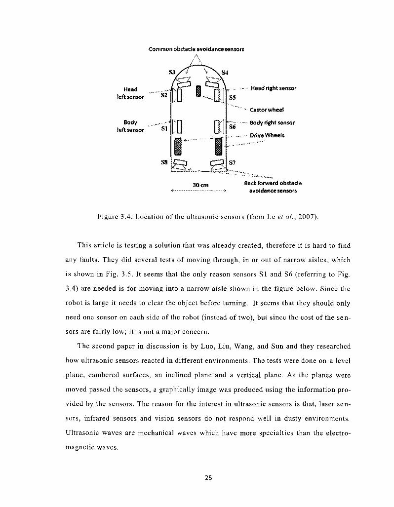
The problem that was approached in the paper by Le Park and Han was a mobile
robot needed to travel through narrow aisles of a warehouse The aisles were 55 cm
apart and the robot was 30 cm in width and 48 cm in length It has eight sensors in orshy
der for the robot to safely maintain a safe distance from an object Figure 34 is a picshy
ture of the mobile robot
Referring to Fig 34 sensors SI and S6 are used to predict if there is an aisle or
corridor opening at either side of the robot Sensor S3 S4 S7 and S8 are used for simshy
ple obstacle detection Lastly S2 and S5 are used to track the centre line of the narrow
aisles and to be able to measure the locus of the aisles centre line (Le et al 2007)
The sensors are firing at a rate of 100 ms meaning all sensor fire once during every
100 ms interval The minimum range for the sensors is 41 cm which is not suitable for
their application They added a custom circuit with each sensor to increase the minishy
mum range to 7 - 10 cm The sensors were placed at the largest visible surface area
which is the top of the skid at 10 cm above ground
24
Common obstacle avoidance sensors
Head _ _ - -left sensor
Body _-mdashmdashbull left sensor SI
S8
0 - 0
D OI
mdash bull Head right sensor
S5
Castor wheel
Slaquo - Bodyright sensor
mdashmdash - Drive Wheels
S7
30 cm Back forward obstacle avoidance sensors
Figure 34 Location of the ultrasonic sensors (from Le et al 2007)
This article is testing a solution that was already created therefore it is hard to find
any faults They did several tests of moving through in or out of narrow aisles which
is shown in Fig 35 It seems that the only reason sensors SI and S6 (referring to Fig
34) are needed is for moving into a narrow aisle shown in the figure below Since the
robot is large it needs to clear the object before turning It seems that they should only
need one sensor on each side of the robot (instead of two) but since the cost of the senshy
sors are fairly low it is not a major concern
The second paper in discussion is by Luo Liu Wang and Sun and they researched
how ultrasonic sensors reacted in different environments The tests were done on a level
plane cambered surfaces an inclined plane and a vertical plane As the planes were
moved passed the sensors a graphically image was produced using the information proshy
vided by the sensors The reason for the interest in ultrasonic sensors is that laser senshy
sors infrared sensors and vision sensors do not respond well in dusty environments
Ultrasonic waves are mechanical waves which have more specialties than the electroshy
magnetic waves
25
Hlaquo~ St laquoraquo bull
Narrow aisle Main
corridor
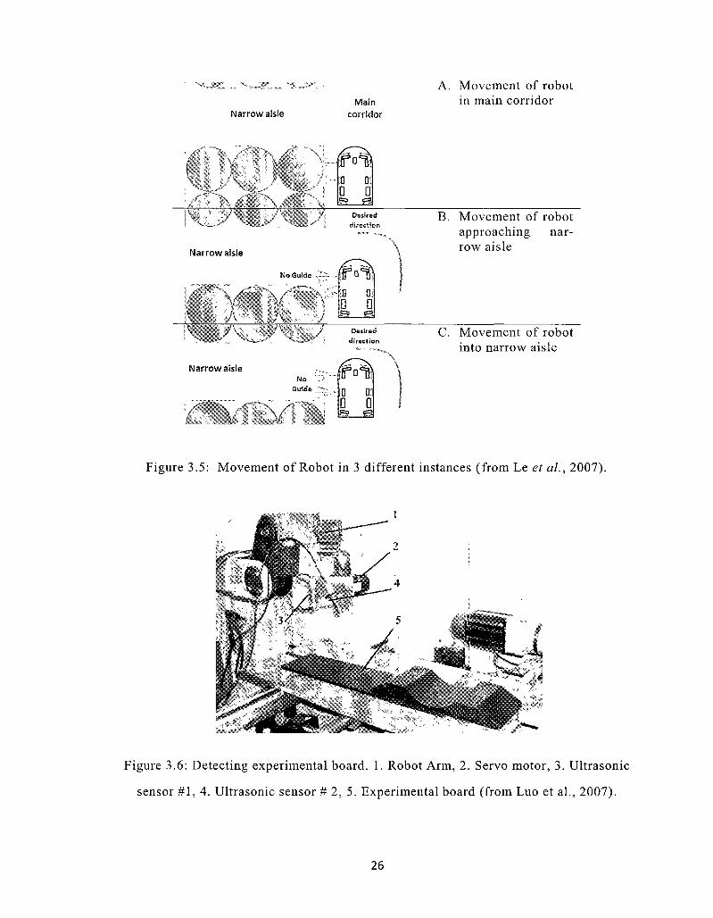
A Movement of robot in main corridor
X I-
J
j
111 Dl 0 D is gs[
y i Oesired
s direction
Narrow aisle
No Guide J-~-
X
v
Narrow aisle
V A JV I
B oj 0 0 laquo3 laquo3
7
B Movement of robot approaching narshyrow aisle
y Desired direction
No Guide
V 0 0 6 S3
C Movement of robot into narrow aisle
Figure 35 Movement of Robot in 3 different instances (from Le et al 2007)
Figure 36 Detecting experimental board 1 Robot Arm 2 Servo motor 3 Ultrasonic
sensor 1 4 Ultrasonic sensor 2 5 Experimental board (from Luo et al 2007)
26
The set-up of the robot is shown below Sensor 1 detects the same level plane and
sensor 2 explores inclines in the plane (2007)
The level inclined and vertical planes were successfully achieved graphically but
the cambered surface was not The vertical plane tested and the results are shown in
Fig 37 The measurement error in height was 07 mm and the error in length was 241
mm The errors are explained to be caused by the dispersion angle from the ultrasonic
sensors
4()nui
(a)
50 100 150 200 250 300 350 400 450 xmm
(b)
Figure 37 Vertical plane used for testing (a) and the exploration results of the vertical
plane (b) (from Luo et al 2007)
There can be several causes for errors the moving speed of the ultrasonic sensor
system errors of the robot experimental system and the processing error of the experishy
mental vertical plane They found that dispersion angle was still the largest factor Er-
27
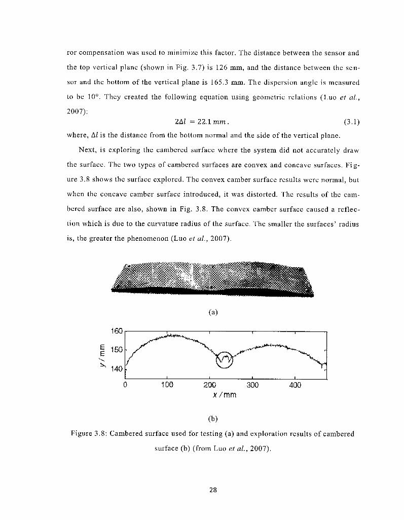
ror compensation was used to minimize this factor The distance between the sensor and
the top vertical plane (shown in Fig 37) is 126 mm and the distance between the senshy
sor and the bottom of the vertical plane is 1653 mm The dispersion angle is measured
to be 10deg They created the following equation using geometric relations (Luo et al
2007) 2AI = 221mm (31)
where Al is the distance from the bottom normal and the side of the vertical plane
Next is exploring the cambered surface where the system did not accurately draw
the surface The two types of cambered surfaces are convex and concave surfaces Figshy
ure 38 shows the surface explored The convex camber surface results were normal but
when the concave camber surface introduced it was distorted The results of the camshy
bered surface are also shown in Fig 38 The convex camber surface caused a reflecshy
tion which is due to the curvature radius of the surface The smaller the surfaces radius
is the greater the phenomenon (Luo et al 2007)
amp
(a)
160
E E
200 300 xmm
400
(b)
Figure 38 Cambered surface used for testing (a) and exploration results of cambered
surface (b) (from Luo et al 2007)
28
Even though this is not directly related to the project in this thesis it is important to
know what ultrasonic sensors are capable of There could be a situation where the robot
will continue straight into an object while the result was an uneven surface that reflects
the wave in a different direction This article was an excellent source of how ultrasonic
sensors could fail and when they would be accurate It also proves that they would be
the best to use in this thesis because of their robustness
322 Flame Sensors
The ultrasonic sensor detects where an object is but is not able to detect a flame Using
a flame sensor integrated with the ultrasonic sensors it can detect the flame and apshy
proach it safely There have been many projects on flame sensors especially the integshy
rity of them (Sims Lesko amp Cox 1998 Glascock amp Webster 1971 Kranz 1995
Erickson 1972)
Clifford Erickson discusses a sensor that consists of a gas-filled tube that uses the
Geiger-Mueller method Geiger-Mueller method is defined as an electron emitted from
a photocathode being accelerated by an applied electric field to causes ionization of the
filled gas This concept is not new but the method which is developed is The cathode
consists of a semitransparent layer of metal on the inside of the cylindrical tube enveshy
lope The cathode was placed in a way that it would provide a wide-angle view or deshy
tection It detects the ultraviolet radiation The tube created was compared to a tube
with the same envelope dimensions but having better conventional parallel wire elecshy
trodes Its sensitivity ranges over 360deg in a plane perpendicular to the tube axis With
recent technologies Hamamatsu has created a flame detector (UV TRON) that comes
with a driver to control the blub The driver circuit is a low current consuming and can
be configured with a 10 to 30 volt dc 5 volt dc or a 6 to 9 volt dc supply Figure 39
shows the UV TRONs spectral response with different light Sources
There are many research projects that are investigating the high-temperature optical
flame sensors (Sims et al 1998 Glascock amp Webster 1971) High temperatures can be
defined as temperatures in between 300 to 500 degrees centigrade These devices are
29
implemented in internal combustion engines gas turbines boilers and different indusshy
trial processes
H
UJ
bull a
n so lt HI egt ai gt t-lt UJ
100 200 300 400 500 600 700 BOO
WAVELENGTH (nm)
ULTRAVIOLET viStAr I INFRARED
Figure 39 UV Trons spectral response and various light sources (from Hamamatsu 1998)
Kranz explained a flame detection method using infrared flame detectors These
devices have been created to detect certain light spectrum which allows it to detect a
flame What is important in this article was not the device used but the improvement on
the device by using normalized cross correlation to improve the detecting of the senshy
sors It helped eliminate false alarms from hot bodies and became more robust against
disturbing radiation
33 Fuzzy Control
A complex behaviour artificial system can be designed based on tasks which are simshy
pler easy to understand and implement Mimicking human intentions is very popular
which is defined as using expert knowledge to create fuzzy rules Many have studied
the behaviour of using fuzzy rules and weighed out the pros and cons Following a wall
following a corridor avoiding an obstacle and so on requires fuzzy knowledge to create
a fuzzy controller Designing rules that can handle the different tasks a robot faces in
an environment need to be created
30
Thongchai and Kawamura (2000) describe in their article how their behaviour-based
fuzzy control works for their Help-Mate mobile robot It was used to implement an inshy
dividual high priority behaviour There were three different behaviours that were deshy
fined emergency behaviour obstacle avoidance behaviour and task oriented behaviour
The emergency behaviour was described as the highest priority than other behaviours
because it was defined as the safety distance from other objects The obstacle avoidance
behaviour was defined by the fuzzy inputs from ten sensors where five sensors were
placed on the front-left and five placed on the front-right of the robot They created five
fuzzy controls for this behaviour The two task behaviours were goal following behavshy
iour and wall following behaviour which were the lowest on the robots priority list By
creating a set of nine rules they designed the following angular velocity output using
the centroid method
= zr=i^(yt)yt (3 2) y ir=i^(X)
They found that larger obstacles resulted in better sonar data information Their findshy
ings were that all obstacles were avoided and all behaviours worked correctly even the
emergency behaviour that would stop the Help-Mate if it got too close to an object
Lee and Cho (2001) described how easy transforming linguistic information and exshy
pert knowledge into a control signal was and explained some of the drawbacks that can
occur It is believed that it is difficult to determine the optimal parameters which they
have proposed to tune the control of the sensor based mobile robot system with genetic
algorithms By creating an algorithm for their fuzzy logic controller they evolved it
using Baas definition of emergence Baas definition of emergence is described as a
universal phenomenon that can be described mathematically It is used to study scienshy
tific legitimate explanations of complex systems (Baas amp Emmeche 1997) Theoretishy
cally it consisted of 228 rules since there were eight input variables two output varishy
ables and four fuzzy sets per variable
31
Some have tried using different layers of architecture Abreu and Correia (2001)
studied a three layer behaviour based architecture using fuzzy logic The architecture
that is described is shown in Fig 310 The bottom-up presentation shows many ellipshy
ses which are made up of other ellipses Each ellipse represents behaviour modules at
some level The line leaving an ellipse is the action and activity values The bottom-up
method was used to be a constructive way to build a robust compliant system Care had
to be taken in computational resources since fuzzy controllers can escalate consumption
of resources quickly This would create an unstable system
Figure 310 Architecture block diagram (from Abreu amp Correia 2001)
A method has been developed to monitor the system in order to improving fuzzy
systems which use a behaviour-based design Lamine and Kabanza (2000) have deshy
signed a monitoring knowledge system that is able to detect failures They constructed a
method to detect uncertainties and noisy information such as salt-pepper and Gaussian
method There are three ways the designer deals with uncertainties eliminate it by enshy
gineering the robot tolerating it by writing robust programs or reason with it by mashy
nipulation (Saffiotti 1999) The method that Lamine and Kabanza designed has a poshy
tential to detect flaws and to either guide designers to fix them or continuously adjust
the control system to adapt to them
32
Chapter 4
The Developed Fire Fighting Robot
System
It can be very difficult to design a robot in todays age with all of the constraints that
need to be considered Drastically changing environments to moving objects cannot alshy
ways be predicted by just using software Researchers need a design that can be built
upon and altered to fit the needs of the environment Currently this robot can navigate
freely in an environment with unknown obstacles Distance sensors were used to detect
objects and to approach the target A flame sensor is installed to detect a fire and act
accordingly In this chapter the hardware and software architectures are discussed The
main designs that are developed are described Then the implementation or testing proshy
cedure is explained
41 Introduction
The robot built for this thesis is shown in Fig 41 It is an autonomous robot its misshy
sion is to search an unknown environment for a flame and extinguish it The robot reshy
acts to sensory inputs that are contained by ultrasonic sensors and a CdS photocell By
extracting information from the environment it continues its path using a group of beshy
haviours This system uses a behaviour-based approach which is able to deal with the
multiple changing goals in a dynamic unpredictable environment (Brooks 1986) The
33
gt
raquoraquo
Figure 41 The designed fire fighting robot
34
main task for the robot is to search for a flame while avoiding obstacles in its path
This chapter will describe the hardware and software architecture of the fully operashy
tional prototype The details described are as follows the mechanical design followed
by the control system and an explanation of the implementation stages
42 Mechanical Design
The robot is designed to be able to detect a flame and extinguish it The heaviest obshy
jects on the robot would be the batteries and the water it carries to extinguish the flame
Naturally the pay load must be considered The body of the robot is constructed out of
05 inch thick plastic sheet The base consists of two circles one at a radius of 369
inches and the second one is 172 inches A dimensioning layout was created in Autoshy
CAD shown in Fig 42 The base is designed with one circle larger than the other in
order to allow for easy movement and detection of where an object is It also reduces
the amount of movement a robot has to take in order to go around an object If it was
square in some scenarios the robot may have to reverse before it turns to avoid collidshy
ing with an object The smaller circle is made to hold the water and air tanks It has the
third wheel fixed under it It is made smaller for both cosmetic purposes and weight reshy
duction
421 Motor Design
Since there will be two motorized wheels they will have to be fairly large for faster
turns and easier movement over uneven floors The third wheel will have to be slightly
smaller than the other wheels to allow it to rotate freely Since the payload may cause
the motors to struggle it will have to be powerful enough to not burn out The third
wheel will have to be able to rotate 360 degrees with the least amount of fiction This
will allow the robot to move without stressing the motors It is not necessary to have a
steering mechanism since it can steer by using the two motorized wheels This actually
decreases the time it takes the robot to turn and make movements
35
Problems that may occur if not designed correctly
1 If the motorized wheels are not centred correctly it may put strain on one of
the motors or slow the unit down
2 If the third wheel is not correctly placed beyond the centre of gravity it may
tip when trying to extinguish the fire
3 If the voltage is distributed incorrectly to the motors it could send the robot
in an unexpected direction
R36875
R17188
Fillet RO 1000-
46250
-Fillet R01000
-05000
Figure 42 AutoCAD render of the base of the robot
Choosing the motors carefully is important because if a motor with low torque was
selected the robot may never move We can prevent this from happening by looking at a
few equations
F = ma (41)
T = Fr (42)
36
If the robot weighs approximately 151b (7kg) equation (41) would equal 07 lbs
(ignoring gravity) accelerating at 01 ftsec2 Using the force (F) we can determine the
torque by using tires that are 2 inches in radius which would equal 14 lbs-in or 22
ounces-in
The motors that have been chosen for this project are the Solarbotics GM3 - Gear
Motors These motors are used in a variety of different applications involving robots
The maximum voltage is 5 Vdc and it has a torque rating of 50 oz-in This is more than
double of what is needed however it will compensate for any overheating or any extra
weight that is added during this project and for future development
The most suitable tires would be the Solarbotics GMPW which is designed for the
GM3 motors They are 2 s8 inches in diameter and 03 inches in width They are fairly
small and light since they are made from injection-moulded ABS plastic It also uses
moulded-on thermoplastic silicon tire with better traction and wear characteristics
unlike some projects that use rubber bands Figure 43 shows the motors and tires that
will be used
Figure 43 Tires and motors (from RobotShop 2009)
There are many different options for interfacing between the controller and the moshy
tors Relays an H-bridge or using the voltage the controller gives out could be used
37
Since the microcontroller that would operate the motor does not provide enough voltage
or current an H-bridge was designed for the system Figure 44 shows the H-bridge
controller built by Steve Bolt (2003) A and B are the controlling signals and as shown
on the diagram the motor is placed between the collectors of all the transistors Transisshy
tor 2N2905 can be used from Ql and Q2 and transistor 2N2219 can be for Q3 and Q4
The third wheel installed is a caster wheel that was purchased from Canadian Tire
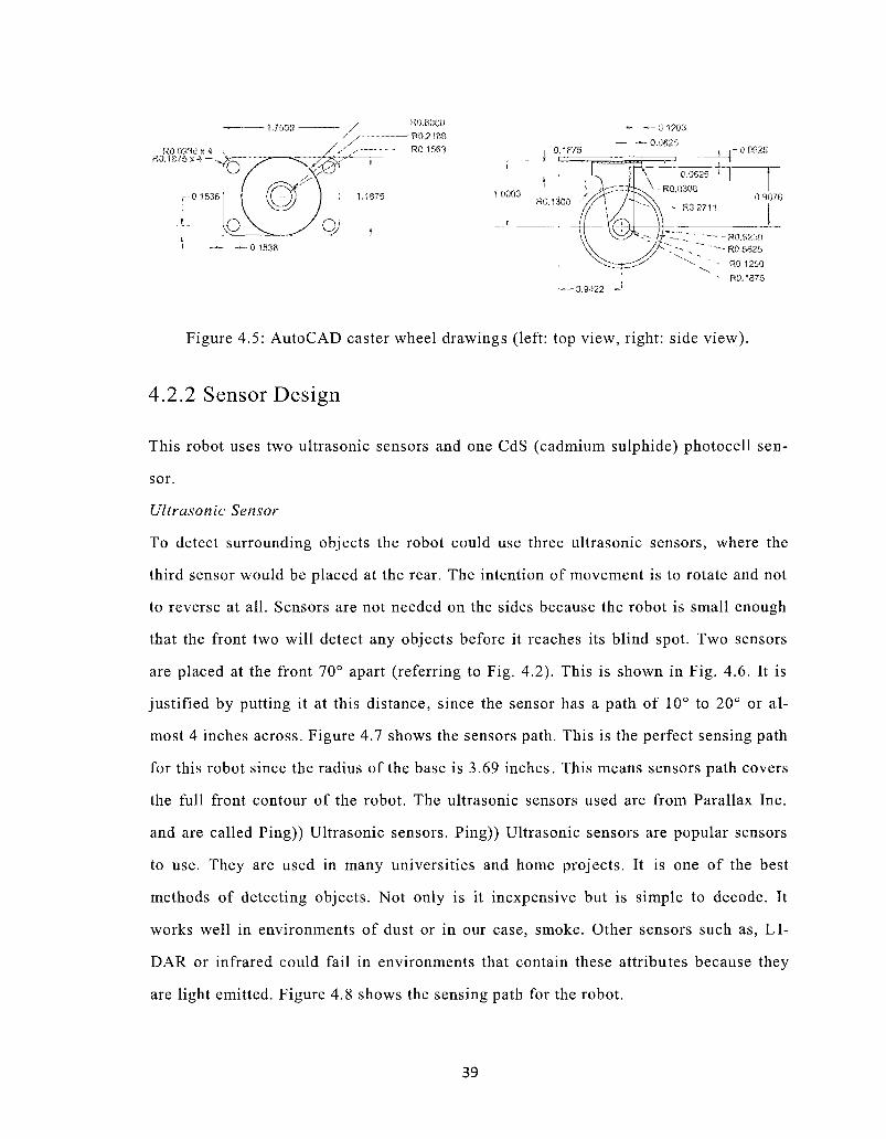
It is 1 inches in diameter and rotates 360deg Figure 45 is an AutoCAD drawing of the
wheel with dimensions
Second H-bridge 180498
copy TttraniMiM
Figure 44 H-Bridge designed by Bolt (from Seale 2003)
38
Figure 45 AutoCAD caster wheel drawings (left top view right side view)
422 Sensor Design
This robot uses two ultrasonic sensors and one CdS (cadmium sulphide) photocell senshy
sor
Ultrasonic Sensor
To detect surrounding objects the robot could use three ultrasonic sensors where the
third sensor would be placed at the rear The intention of movement is to rotate and not
to reverse at all Sensors are not needed on the sides because the robot is small enough
that the front two will detect any objects before it reaches its blind spot Two sensors
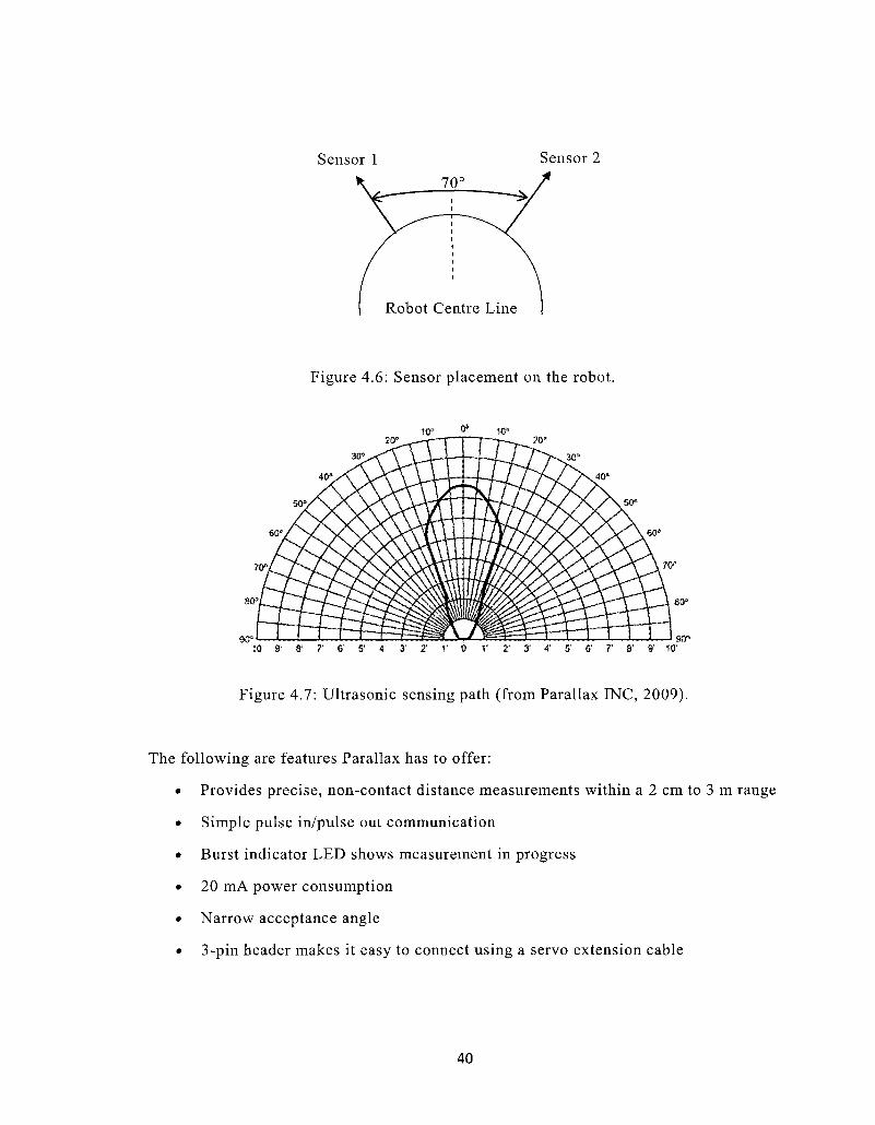
are placed at the front 70deg apart (referring to Fig 42) This is shown in Fig 46 It is
justified by putting it at this distance since the sensor has a path of 10deg to 20deg or alshy
most 4 inches across Figure 47 shows the sensors path This is the perfect sensing path
for this robot since the radius of the base is 369 inches This means sensors path covers
the full front contour of the robot The ultrasonic sensors used are from Parallax Inc
and are called Ping)) Ultrasonic sensors Ping)) Ultrasonic sensors are popular sensors
to use They are used in many universities and home projects It is one of the best
methods of detecting objects Not only is it inexpensive but is simple to decode It
works well in environments of dust or in our case smoke Other sensors such as LI-
DAR or infrared could fail in environments that contain these attributes because they
are light emitted Figure 48 shows the sensing path for the robot
39
Sensor 1 Sensor 2
Figure 46 Sensor placement on the robot
laquor deg w
10 9 8 7 6 5 4 3 2 1 0 1 Z 3 4 5 6 7 8 9- 10
Figure 47 Ultrasonic sensing path (from Parallax INC 2009)
The following are features Parallax has to offer
Provides precise non-contact distance measurements within a 2 cm to 3 m range
Simple pulse inpulse out communication
Burst indicator LED shows measurement in progress
20 mA power consumption
Narrow acceptance angle
3-pin header makes it easy to connect using a servo extension cable
40
Ultrasonic Sensing Angle
Figure 48 Sensing angle for the robot
The distance from an object can be calculated by using the time it takes the sound
(chirp) to travel to and from an object The transmitter sends a signal out (a sound that
cannot be heard by human ears) and waits for a signal to be received (echo) by the reshy
ceiver The time it takes to receive the signal can be converted into the distance of an
object from the sensor We can make the assumption that sound travels at approxishy
mately 112 ftms (034 mms) This can be calculated by using the equation below
(Beranek 1972)
c(T) = 1087 l+-r=z bull (4-3) K J 273
where c(T) = speed of sound in air as a function of temperature (feetmilli-seconds) and
T is temperature of the air in degC
To simplify the calculation we can inverse c(T) and multiply it by 2 to get the round
trip (going to the object and back) This equals 178 msft (584 msm) The distance
can be calculated by calculating the time it takes the chirp to leave the transmitter and
be received at the receiver therefore dividing it by 178 msft (584 msm) (Greenwald
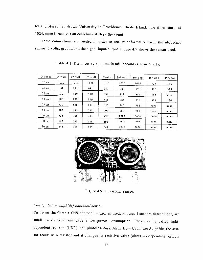
2007) Table 41 shows distance versus decremented time from 1024 that was calculated
41
by a professor at Brown University in Providence Rhode Island The timer starts at
1024 once it receives an echo back it stops the count
Three connections are needed in order to receive information from the ultrasonic
sensor 5 volts ground and the signal inputoutput Figure 49 shows the sensor used
Table 41 Distances versus time in milliseconds (Dean 2001)
Distance
10 cm
20 cm
30 cm
40 cm
50 cm
60 cm
70 cm
80 cm
90 cm
0deg-wall
1020
981
930
885
834
783
738
687
642
0deg-obst
1019
981
929
879
828
783
738
681
648
15deg-wall
1020
981
930
879
834
783
731
686
635
15deg-obst
1019
981
930
885
835
790
738
693
647
30deg-wall
1020
981
931
385
386
782
none
none
none
30deg-obst
1019
975
385
878
386
789
none
none
none
45deg-wall
937
386
386
386
none
none
none
none
none
45deg-obst
386
386
386
386
none
none
none
none
none
Figure 49 Ultrasonic sensor
CdS (cadmium sulphide) photocell sensor
To detect the flame a CdS photocell sensor is used Photocell sensors detect light are
small inexpensive and have a low-power consumption They can be called light-
dependent resistors (LDR) and photoresistors Made from Cadmium Sulphide the senshy
sor reacts as a resistor and it changes its resistive value (ohms Q) depending on how
42
much light it detects Although some may speculate that this sensor is not adequate for
this research project with the correct resistance value and filters it is easily able to
block out certain spectral wavelengths of light Figure 410 shows the sensor used This
sensors resistance can vary from 5k ohms to 500k ohms It has a maximum voltage and
power consumption of 100 VAC and 60 mW respectively The peak spectral response
is 630 nm which is in the infrared spectral response The sensor has two leads which
are an input and output The diameter of the sensor is 5 mm
Figure 410 CdS photocell sensor
423 Flame Retardant
There are many methods to put out a flame such as a powerful fan which is extremely
popular in competition robots A chemical base product could be used such as C 0 2 or
water This project uses water to extinguish the flame similar to a fire extinguisher conshy
cept Fire extinguishers are filled with water and compressed air The compressed air
allows the water to be pressurized and come-out with a burst when it is engaged Usushy
ally the pressure within the vessel which depends on the size of the unit is above 100
psi The robot in this thesis has been built with two holding tanks one for the water and
one for air Once the compressed air is released into the water tank the water squirts out
of the nozzle and extinguishes any flames in sight
43
424 Control System
The overall Architecture of the mobile robot is mapped in Fig 411 The brain of the
system is the microcontroller from Atmel (ATmega644) It is an 8-bit microcontroller
with 8K bytes in-system programmable flash It has many features such as an advanced
RISC (reduced instruction set computer) architecture which has
bull 131 Powerful Instructions - Most Single-clock Cycle Execution
bull 3 2 x 8 General Purpose Working Registers
bull Fully Static Operation
bull Up to 20 MIPS Throughput at 20 MHz
There are many other feature but these are the most important In order to program
the microcontroller an AVRISP mkll programmer was used When connected hex files
which contained the code were uploaded to the microcontroller Since simple assembly
was used it was a simple operation of setting bits to either a low (0) or a high (1)
status The assembly program can be found in Appendix A Usually the voltage a port
that the microcontroller can produce is from 28 - 50 volts The microcontroller and all
other control components were soldered onto three separate boards as illustrated in Fig
412 A small computer fan was placed in front of the boards to keep them cool The
transistors have a tendency of heating up The wiring diagrams for the three control
boards are show in Fig 413 Fig 414 and Fig 415 Control board 1 contains the H-
bridges for the motors (Fig 413) control board 2 contains the microcontroller (Fig
414) and control board 3 is used for the fire extinguishing system (Fig 415)
44
CdS Photocell Sensor
Sensor 1
bull bull
5VDC
Power Supply
Microcontroller
_ plusmn Motor Control
J t
Sensor 2
r~mdash
Motor Control
18V DC Power Supply
FES Controller Unit
Motor 1 Motor 2
Flame Extinguishing Switch (FES)
Figure 411 The schematic of the control design
Figure 412 Control boards for the fire fighting robot
45
To Base Ports
D1 D2 | | D3| D4|_
R2 iJ U| |l i W^^^-|Q1 OiJ-t
R4 i gt k R3 R7 i ^ k R9 W A |T3 T2JJmdash-gtAmdash fmdashWVmdash|T1 T4 1mdashWA
S1 GN3 5V S2 S3 S4
To Con t ro l Boa rd 2
R1 R9 = 1 K o h m
Q 1 Q 5 = 2 N 2 9 0 5
T1 T5 = 2 N 2 2 1 9
R5 mJ L i I R8 |mdashWA 104 Q3T+-AWV
J
Figure 413 Electronic schematic for the H-bridge control board
To Baso Ports (Port 2) To Programmer (Port 1
G N D 5V NC|NC|NC[NC| GND
R1 mdashWWtrade C RESET
VCC vcc VCC
XTAL2 XTAL1
AREF AVCC
GND GND GND GND
RESET]
ATMEGA644A
SCK
lPCINT7ADC7)M7 (PCINT8ADC6JPA6 PCINT5ADC51PA5 (PCINT4ADC4)Hi4 (PCINT3ADC3)RA3 (PCINT2ADC2)B2 (PCINT1 ADC11R41 PCINTQADCOJPAO
iPCINT15SCKPB7 (PCINT14MISQ1P86 tPCINT13MOSISP65
PCNT12OC0B35gtPB4 IPCiNTHOC0AA[N1PB3 (PCINTialNT2AIN0gtP62
bull PCIM9ClKampT1gtPBi lPCINT8XCK0TOPB0
PCfNT23TOSC2PC7 (PCSNT22T0SC1)PC6
(PCINT21 TDI)PC5 |PCINT20TDO)PC4 (PCINT19TMS)PC3 ltPCINT18TCKiPC2 (PCINT17SDA)PCt (PCINT1ampSCUPC0
(PCINT31 OC2APD7 (PCINT3aDC2B-ICP)PD6
(PCINT29 0C1AIPD6 iPCINT28OC1BPD4
(PCINTZ7 INT1 PD3 (PCINT26INT0IPD2
(PCINT25TXD01PD1 PCINT24fRXD0)PD0
15 14 13 12 11
FS = Flame Sensor
US1 = Ultrasonic Sensor 1
US2 - Ultrasonic Sensor 2
M I S O MDSI
A1 | 2 2 To Control Board 3 (Port S)
SV GNJUD1 D2 D3 D4
NC NC FS U S i To Base Ports (Port 4)
U S 2 NC
To Control Board 1 (Port 3)
Figure 414 Electronic schematic for the microcontroller control board
46
To Control Board 2 To Base Ports
A1 A2 GND 5V 1 NCI NCI RELAY
5V
R11 -AMVmdash-1 kohm
R12 --WWmdash 1 kohm
Q5 j 2N2905
R13 -AWV-
T5 2N3904
47 k ohm i T6
I2N2219
(c)
Figure 415 Electronic schematic for the fire extinguishing system control board
425 Power Supply
There are two different voltage supplies that are commonly grounded 18 volts DC and
5 volts DC The 18 volts is for the flame extinguishing switch control unit as shown in
Fig 411 The 5 volts supplies the microcontroller the motors control and the sensors
The 18 volts supply will last a life time or until the batteries expire since it is only used
when extinguishing a flame It was not necessary to have high current batteries thereshy
fore two 9 volts alkaline batteries were used The 5 volts supply on the other hand
lasted approximately 4-5 hours during testing Four 12 volts nickel-metal hydrides batshy
teries were used which have a current rating of 2300 mAh each
43 The Kinematics of the Robot
Most vehicles seen on the road today have four wheels or for a motorcycle two wheels
but not many are constructed with three Although the three wheelers may not be found
on the road many are found in solar car racing In many races the top contestants are in
three wheeled cars Most are designed with two wheels in the front and one in the back
The issue with these vehicles is the stability If they are not created properly it can be
47
disastrous The designs of these vehicles are very similar to the design of the mobile
robot in this thesis In the dynamics of a vehicle it is important that the centre of gravshy
ity (CG) is located in the correct position This would reduce tipping of the vehicle reshy
duce steering correction at high speeds and reduce resistance in hard braking from the
weight transfer from the rear to the front Although not all of these conditions apply
directly to the mobile robot since the robot is not moving at high speeds or braking
hard but it is still important for tipping The tipping of the vehicle becomes a greater
problem when the vehicle becomes narrower In order to overcome this problem deshy
signers introduced a hydraulic tilt mechanism that would lean the drivers cabin into a
corner such as a motorcycle driver would
The best way to represent the robot is to represent it in a Cartesian method and poshy
lar coordinate systems Figure 416 shows the robot in Cartesian and polar coordinate
system
With the robot represented by a point its kinematics equations in a Cartesian space
can be expressed as
x mdash v cos 9
y = v sinQ (44)
6 =o)
where co defines the orientation of the robot according to a global reference shown in
Fig 416 Expressing the polar reference associated with the goal is achieved by the
following equations (Aicardi et al 1995 Belkhouche 2007)
p = mdashv cos a
sin a
6 = -a
48
y
yi
yr
k
^ Goal
4 laquo
CO sK k A |0
( ^ gt ^ _ V x
Jr Vi
Figure 416 The robot represented in Cartesian and polar coordinate systems
This model can be extended to different types of robots for example instance synshy
chronous drive robots or differential drive robots More details will be explained in
Chapter 5 about the robots navigation process
44 Implementation
After performing some general testing with the hardware the software was written to
avoid objects without a target or goal First the ultrasonic sensors had to be configured
in order to detect objects at different distances After finding the adequate distance
which was 10 cm the robot was exposed to a series of tests in different environments
49
Test one forward reverse left turn and right turn
With the correct voltage connected to the motors the base was able to move forward and
reverse in a straight line This was a concern during the construction of the base If one
of the motors was placed at an angle it would start to force a turn in one direction This
would cause a strain on the motors since it would be forcing a direction on the other
motor An example of this would be the steering alignment of a vehicle To adjust for
movement of the motor (or to fix the alignment) the bracket that houses the motors are
adjustable
To turn the robot the voltages are simply reversed between the motors This allows
the robot to practically spin on a dime As mentioned before if the alignment was off
the robot could go in a different direction and strain would be put on the motor
Test two grade test
With the same flooring used in test one which was ceramic flooring the robot was subshy
jected to various degrees of inclines The increments were increased by 15deg the robot
started to slide at 45deg The ceramic flooring was the first to slide while the hardwood
and carpet were at a slightly greater angle
Test three obstacle avoidance
After the first two tests were completed the robot was put through a series of obstacle
avoidance tests It was placed on ceramic tiled floor and had to avoid several objects
Some of the objects were cabinets corners of a fridge and chairs All of these objects
are regular house hold items which proves it would be able to manoeuvre successfully
in a house
Next it was subjected to a corner If it cornered itself would it be able to make its
way out Yes it did Not only does the programming get it out of the corner but it
makes sure it does not end up back in the corner The last test was activity under a
chair
50
There were some concerns since there are only two sensors and a blind spot directly
in the front of the robot The blind spot was minimal since the reflection echo was
strong enough to detect
Test four flame detection and extinguishing
Once these tests were complete the flame detection and flame extinguishing systems
were installed and the final tests where implemented A candle was set in a room the
robot had to find and extinguish it The test was successfully completed three times
with the flame in different positions and in different rooms
45 Summary
The fire fighting robot was developed with the purpose of finding and extinguishing a
flame in an unknown environment To design a mobile robot that has these capabilities
many aspects needed to be considered This project is being designed in hopes of future
construction of fire fighting robots they will help save lives and reduce financial probshy
lems The behaviour-based approach is successful implemented by using many sensors
that help guide its way through an environment and avoiding obstacles The behaviour-
based method mimics human tendencies to the fullest of its abilities This robot has the
ability to autonomously navigate in areas with different grades and different surfaces
The experiments conducted with the robot prove the effectiveness of the design created
51
Chapter 5
Obstacle Avoidance using Fuzzy Logic
The fuzzy control is a system which can handle the combining sensory information
from the ultrasonic sensors and provide a useful outcome Since ultrasonic sensors proshy
vide a large range of information it needs to be understood and configured for the speshy
cific needs The primary objective other than finding the target is to be able to navishy
gate freely in an unknown environment and avoid obstacles Two ultrasonic sensors are
used to navigate avoid obstacles and to approach the target The fuzzy techniques are
integrated into the hardware and are used to control the robot The hardware used is the
Atmels ATmega644 chip which is a 8-bit microcontroller The software designed in
this thesis is behaviour-based which means it mimics a more biological like action
These biological actions are based on knowledge that mimics human actions
This chapter will describe the fuzzy controller developed for the fire fighting robot
The theories of taking the raw sensory data and using it to navigate the robot will be
explained At the end of this chapter testing on the robot is performed to conclude that
the method is executing correctly
51 Introduction
When a mobile robot is entering an unknown environment it must have a goal whether
it be obstacle avoidance target approaching or following a wall In this section obstacle
avoidance is discussed The sensors selected for this task is extremely important due to
52
the possible lack of technologies some may have In this thesis ultrasonic sensors are
used to measure distances between the robot and other objects Information used from
data provided by the ultrasonic sensor can determine the distance between the sensor
and object As discussed in the literature survey ultrasonic sensors work in dust condishy
tions while some such as infrared sensors could fail (Luo et al 2007) Since the robot
designed in this thesis is a fire fighting robot using ultrasonic sensors is a wise decishy
sion because of the smoke it could potentially encounter
There are many different studies done in sensor fusion for robots or other device
that measure distances Ultrasonic sensors are not exclusive to distance measurements
since they can also be used for other things such as using ultrasonic sensor disks for
detecting muscular force (Tanaka Hori Yamaguchi Feng amp Moromugi 2003) Alshy
though these types of sensors are mostly used for research in distances between objects
(Bau Shen amp Li 2010 Le et al 2007 Magori 1994 Song amp Tang 1994 Tsai 1998
Yata Ohya amp Yuta 2000)
The ultrasonic sensors will be used to measure distances between itself and other
objects By calculating the time it takes the signal to go from the sensor to an object
and back computational codes can determine the distance the sensor is from the object
The computational code can be referred to as fuzzy rules
For many years different techniques have been designed for robot navigation using
the sensory information given Earlier techniques involved using an artificial potential
field (Borenstein amp Koren1991 Haddad Khatib Lacroix amp Chatila 1998) It was an
attractive force that was produced by goals which drives the robot to the object and the
repulsive forces keeps the robot away from obstacles After improvements were made
some new techniques were introduced Virtual Field Histograms (VFH) is a real time
motion planning algorithm created by Johann Borenstein and Yoram Koren It was deshy
veloped in 1991 and used a histogram grid to statistically represent the environments of
the robot There was an emphasis on uncertainties from sensor and modeling errors
Another method called the Curvature Velocity Method (CVM) was originally developed
by Reid Simmons Considering the objects direction of the goal and distance from an
53
obstacle the CVM chooses both the translational and rotational velocities of the robot
while staying within the constraints of physical limitations For synchro-drive and non-
holonomic robots it works well but does not respond well with differentially steered
robots (Quasny Pyeatt amp Moore 2004) Dynamic Window Approach (DWA) was anshy
other real-time collision avoidance strategy developed by Dieter Fox Wolfram Bur-
gard and Sebastian Thrun In 1997 it was designed to reduce search space to the dyshy
namic window It is commonly used in constraints that impose limited velocities and
accelerations of a robot CVM and DWA are also popular in high speed navigation Adshy
ditional designing of the Dynamic Window Approach has been developed by many
(Arras Persson Tomatis amp Siegwart 2002 Berti Sappa amp Agamennoni 2008 Brock
amp Khatib 1999 Ogren amp Leonard 2005 Philippsen amp Siegwart 2003)
Fuzzy controls since 1965 has been an extensive research Lotfi A Zadeh was the
first to purpose fuzzy logic in 1965 Thereafter research was done in fuzzy systems and
the first industrial application was built and on the manufacturing line in 1975 by FL
Schmidt amp Co They made a cement kiln built by using Zadeh methods Proposed in
1975 by Ebrahim Mamdani was an attempt to control a steam engine and boiler combishy
nation by synthesizing a set of linguistic control rules (Mamdani amp Assilian 1975) The
Japanese stated to implement fuzzy control systems for the Sendai railway In 1987 the
fuzzy systems were used to control acceleration braking and stopping In that year and
many years following fuzzy controls were implemented and tested with increasing inshy
terests while enhancing products at home and at the industrial level Industres sought
the greatest impact with machinery control processing control and intelligent sensory
The popularity today is because of the problem solving control methods fuzzy sysshy
tems allow Not only is it easy to create but it is easy to understand with simple rule-
base formulas
The behaviours of the robot will be implemented by using a set of fuzzy rules which
are created to mimic human knowledge There have been many that have researched in
areas with fuzzy logic especially within robotics (Fukayama Ida amp Katai 1999 Joshi
amp Zaveri 2009 Lei amp Li 2007 Rusu Birouamp Szoke 2010) Fuzzy logic can deal
54
with imprecise data which in obstacle avoidance can be the case With ultrasonic senshy
sors sometimes there are reflections of wave that can give incorrect information Since
fuzzy logic applies a feel of human like behaviours it is easier to design This explains
the reason why navigation processes using fuzzy logic is so popular Originally fuzzy
control was designed for sorting and handling data but has proven to be useful for
many different types of control systems
In this chapter the fuzzy rules are successfully designed to avoid obstacle and folshy
low walls It was tested on the prototype robot and showed excellent results
52 The Concept of Ultrasonic Sensors
Before a fuzzy controller is designed an understanding of ultrasonic sensors must be
discussed In order to communicate to the sensors and receive information from them a
microcontroller must be connected to it The microcontroller will send a positive TTL
(Transistor-transistor logic) pulse to the ultrasonic sensor and will wait to receive an
echo back It sends a signal to the sensor the ultrasonic sensor sends out a burst or
chirp that travels to an object and returns in a reflection The distance can be calcushy
lated by using the time it takes the sound (chirp) to travel to and from an object Figshy
ure 51 illustrates the signal being sent from the microcontroller to the sensor the burst
signal and the potential time when it would arrive Table 51 shows the typical time
frames you can expect the sensors to function at
Each sensor during normal operation (when no object is in front of each sensor) is proshy
grammed to activate every 213 ms to 626 ms depending on how far an object is from
the sensor If an object is presented in front of the robot it would take longer as the time
it takes the robot to get out of the objects path must be considered Temperature and
air quality do affect sensors but not enough to drastically change their characteristics
55
SG pin
Sonar TX
-t OUT IN-M1N
bull 5v
Ov
bull u
Figure 51 Signals from the ultrasonic sensor (from Parallax 2009)
Table 51 Typical values for sensor (Parallax 2009)
Host Device
PING))) Sensor
Input Trigger Pulse
Echo holdoff Burst frequency
Echo return pulse minimum Echo return pulse maximum
Delay before next measurement
bullout
tHOLDOFF
tBURST
tlN-MIN
tIN-MAX
-
2 LIS (min) 5 LIS typical 750 us
200 LIS 40kHz 1 1 5 LIS
185 ms 200 LIS
53 Fuzzy Control for Obstacle Avoidance
The fuzzy controller is a simple architecture with inputs and outputs Figure 52 shows
a block diagram of the fuzzy controller The data from the ultrasonic sensors are read
by the microcontroller onboard the robot and interoperated by the fuzzy logic software
The controller has two ultrasonic inputs (USiUSR) and has two outputs for the motor
control (mLmR) The subscripts stand for left or right motor or ultrasonic sensor The
output velocities are either forward action (the wheel is moving forward) or a reverse
action (the wheel is moving in reverse) It will be referred to as a positive velocity for
forward action and a negative velocity for a reverse action The logic of the fuzzy conshy
troller is divided into nine separate fuzzy logic controls All rules need sensory input
56
from both sensors with one at last state known The fuzzy behaviours is programmed in
assembly and uploaded onto an 8-bit microcontroller
Fuzzy Controller
Inputs
USL
USR ^gt
Fuzzification - bull
Rules Base
bull
Inference Mechanism Unit Defuzzification
Outputs
mL
mR
Figure 52 Block diagram of the fuzzy controller
531 Fuzzification
The fuzzification procedure is comprised of the transformation of crisp (discrete) valshy
ues into levels of memberships for linguistic terms of fuzzy sets Frequently fuzzy decishy
sion systems are implementing non-fuzzy input data and mapping them to fuzzy sets by
treating them as trapezoid membership functions Gaussian membership functions
sharp peak membership functions triangle membership functions etc
There are two ultrasonic sensors installed on the mobile robot Both sensors are on
the front are placed 70deg apart as previously shown in Fig 46 in Chapter 4 Three memshy
bership functions are used for each ultrasonic sensor in collision avoidance (Fig 53)
The first membership function defines the object as being too far so it is necessary for
it to find a wall The second membership function is if the object is in-between too far
and too close therefore the robot is to continue its path The third membership function
is to steer away the robot from an object when it is too close
57
Too x A Close In Between Too Far
1 A
f Y 1 bull
20 160 300 Distance (cm)
Figure 53 Input membership functions for distance
532 Inference Mechanism
The inference mechanism unit is responsible for decision making in the fuzzy system
By using fuzzy rules it will convert the input information into output membership funcshy
tions It is usually a combination of IF-THEN statements In order to design the fuzzy
rules expert knowledge must be obtained in performing control tasks Since these rules
are created on experimental results it can be tedious since trial and error will have to
be practiced The fuzzy logic system stores the rules that propose relationships between
the inputs and outputs
The obstacle avoidance behaviour is very systematic It has to have the highest prishy
ority in comparison to target tracking or navigation behaviours since it is vital to the
robot to steer away from danger
Since there are only two sensors (for placement see Fig 46 in Chapter 4) the robot
only recognizes that there is either an object on the left side or the right side of it If
there is an object directly in front of the robot it will detect this and force a turn to
avoid any collisions If there is an object on the left side the command would be to steer
right and if there was an object on the right the command would be to steer left Figure
54 demonstrates the obstacle avoidance behaviour Below are distances an object is
58
from the sensor and they are quantized into the following groups The vector USn =
USLUSR is the ultrasonic sensor vector USL is the left sensor and USR is the right senshy
sor
t TCforO lt st lt 20 cm USn= IB for 20 lt 5 lt 300 cm (51)
( TF for 300 lt s
where s is the sensors distance value
After quantifying the distances six rules have been formulated for each sensor Tashy
ble 52 shows the rules for both ultrasonic sensors Negative represents reverse direcshy
tion no change represents continuing its path and positive is a forward direction Rule
set 3 is a special case scenario where both sensors have detected an object This can
happen if it has found itself in a corner or the distances are too far on both sides The
rule will force it into a right turn This is illustrated in Fig 55
Table 52 Rules for ultrasonic sensors
Rule sets
1
2
3
Input (discrete value) detected signal
USL
USR
USR and USL
Outputs
mL
mR
mL
mR
mL
mR
Output for Too Close
Positive
Negative
Negative Positive
Positive
Negative
Output for In Between
No change
No change
No change No change
-
-
Output for Too
Far
Positive
Negative
Negative
Positive
Positive Negative
59
bull ^
Heading Obstacle
Obstacle Detected by Right
ultrasonic sensor
Figure 54 Obstacle avoidance example
The three rule sets are not enough to keep the robot out of trouble therefore a few
fuzzy commands were formulated from experiences during testing These rules were
implemented to reduce sensory errors
1 If in motion and sensor A (it does not matter if it is the left sensor or right
sensor) detects an object after the signal has been sent to change directions
then check sensor A again This is to confirm that the object is not in the roshy
bots path Repeat until it is clear then check the other sensor
2 Delays have been placed in-between codes to reduce errors In theory these
error should not occur but unfortunately they do During the testing process
it seemed to skip some instructions We must keep in mind that the controlshy
ler is working in micro-seconds In order to make sure it processes signals
60
properly the delays slows it down allowing it to process all vital instrucshy
tions
Wall Wall
Both sensor detect object
^
Heading
Figure 55 Cornering avoidance example
As shown in Fig 47 in Chapter 4 the peek or the greatest sensing distance for the
ultrasonic sensor is at 0deg and the sensors maximum width is at 20deg both ways If the obshy
ject is on the inside of the sensor (referring to Fig 46 in Chapter 4) meaning the obshy
ject is at 20deg from the centre line of the robot it will take a longer time to move away
from the objects The two sensors are placed at 35deg on either side of the robot If the
object is on the outside of the sensor placement (45deg) it would have a shorter time of
movement This will be referred to as interval time (t) The greater the interval time
value the more time it will take to turn Figure 56 shows the different angles Although
this information is not critical to the fuzzy controller it is important to understand the
61
behaviour of the robot It is useful for troubleshooting when systems are not working
correctly The time intervals are quantified into the following groups below
ti
(4 for 0deg lt a lt 20deg 3 for 20deg lt a lt 35deg
lt 2 for 35deg lt a lt 50deg 1 for at gt 5 0 deg
^0 otherwise
(52)
where at is the angle in degrees from the centre line of the robot
Left Sensor
K
35deg
40deg
Right Sensor
Robot Centre line
Figure 56 Angles and sensory placement for the robot
533 Defuzzification
The procedure of defuzzification is the conversion of the fuzzy outputs from the infershy
ence mechanism into a discrete variable There are many different methods used to
convert the inference mechanism to an actual output fuzzy controller Many are listed in
section 531 Fuzzification In this thesis the centre of gravity (COG) defuzzification
method is used Referring to the equation below let bt denote the centre of the member-
62
ship function of the consequent of rule i and laquo([) denote the area under the membershy
ship function n^y Therefore the output (x is calculated by
_ Z^Jnydx (52)
Figure 57 shows the output membership function for mL and mR Where negative is
a reverse direction zero is no movement and positive is a forward direction Both can
easily be computed by using ml JV(() dx with the symmetric triangular output membershy
ship functions The peaks are at a height of one and have a base width of to Using geshy
ometry it can be shown that the area under the triangle at height h is equal to co(h - h 2 )
Negative ^ireg) Zero Positive
o e
Figure 57 Output membership functions for motor direction
54 Experiments
The robot was tested in several different environments It was placed on ceramic tiled
floor and had to avoid several objects (Fig 58 Fig 59) Some of the objects were
cabinets corners of a fridge and chairs All of these objects are regular household
items which prove it would be able to work its way around a house This requires the
combination of both sensors and all of the behaviours that are implemented into the sysshy
tem raquo
63
The second test was to see its ability to move out of a corner (Fig 510) When both
ultrasonic sensors detect an object in its path at the same time it proceeded to rule set 3
in Table 52 This is a very important task since this robot is small it can get into small
spaces but if it can not get out it become useless
The last test was testing its behaviour under a chair (Fig 511) There were some
concerns since there were only two sensors and a potential blind spot directly in the
front of the robot It was found that the blind spot was minimal and the reflection echo
was strong enough to detect the obstacles
Test two and three were experimented on carpeted floors which meant that the moshy
tors received enough power from the H-bridge (421 Motor Design in Chapter 4) When
approaching objects it behaved smoothly and accurately The result of the fuzzy obstashy
cle avoidance behaviour is promising The figures below are of the mobile robot during
testing phase before the flame and fire extinguishing units were installed
Figure 58 Robot on ceramic tiled floor exploring the kitchen
64
Figure 59 Robot on ceramic tiled floor steering its way through a corridor
Figure 510 Robot on carpet floor getting out of a corner
Figure 511 Robot on carpet floor steering its way under a chair
55 Summary
Many control techniques have been used on robotic systems The majority are successshy
ful in deployment in a variety of applications Fuzzy behaviour-based control is becomshy
ing a popular method of choice when choosing an intelligent control system Behavshy
iours that are implemented into the control system can be decomposed into several difshy
ferent elements while each one is represented by a fuzzy reasoning The fuzzy techshy
nique proves a promising method The control system kept the sensory errors low with-
65
out affecting any attributes It also reduced the amount of computation compared to
conventional controllers which would directly result in continuous computation The
proposed obstacle avoidance method was applied to the developed mobile robot and the
effectiveness of the method was demonstrated through experiments
66
Chapter 6
Target Approaching using Sensor Fusion
and Fuzzy Logic
Target approaching can be achieved in several different ways To accurately approach a
target the sensor fusion method should be taken Using multiple sensors to detect the
objects location can provide more accurate results than just using one A photocell senshy
sor or a light dependent resistor (LDR) is used to detect the target and ultrasonic senshy
sors are used to detect the distance from the target Using the fuzzy logic concepts a
systematic method is used to interoperate the sensors outputting data Two ultrasonic
sensors are mainly used to navigate and avoid obstacles When the target is detected by
the photocell sensor the ultrasonic sensors are used to navigate the robot to the object
The fuzzy techniques are integrated into the hardware which are used to control the
robot The hardware used is Atmels ATmega644 chip which is an 8-bit microcontrolshy
ler The software designed in this thesis is behaviour-based which means the robot will
show a more biological appearing action These biological actions are based on knowlshy
edge that mimicks human actions
This chapter will describe the fuzzy control developed for the target approaching
system The theories of taking the raw sensory data and using it to navigate the robot
will be explained At the end of the chapter testing on the robot is performed to conshy
clude that the method is executing correctly
67
61 Introduction
When a mobile robot is entering an unknown environment it must have a goal whether
it be obstacle avoidance target approaching or following a wall In this section target
approaching is discussed A CdS photocell sensor is used to detect a flame The sensor
is shown in Fig 410 in Chapter 4 With a custom filter it will be able to direct the roshy
bot in the correct direction towards a flame The ultrasonic sensors will be used to calshy
culate the distance from the flame and notify the controller when it is close enough to
the flame
There are many research papers that discuss flame sensors but most are about exshy
pensive industrial grade detectors (Zhang Li Xu amp Wang 2009 Kranz 1995
Glascock amp Webster 1971 Sims et al 1998) Kranz focused on the carbon dioxide
that radiates from a flame and produced a new method of getting more accurate results
when other disturbing radiations are present (1995) Others are designing detectors that
can sustain temperatures up to 540degC Although this is not needed for our situation the
method of reducing other inferences and the method of building filters for the sensors
are needed
The CdS photocell produces a resistance across the two metallic leads it is packaged
with When the photocell does not detect a light the resistance is high Once it starts to
detect light which depend on the intensity of the light the resistance decreases This
can be converted to a digital signal by adding voltage in series By using fuzzy systems
it can be implemented into the system
The mobile robot is guided by on-board information that is acquired from different
inputs while navigating through the environment With different tasks it requires difshy
ferent priorities and a global goal Successful results are achieved with several fuzzy
strategies designed in this section Fuzzy logic control is designed to direct the wheels
to steer the robot in different directions Since it is only a three wheel system no steershy
ing motor is needed The two motorized wheels are able to turn the robot in either di-
68
rection Following a target can be easily achieved by steering towards the direction of
the target
Precise numerical information is not needed with fuzzy logic With sensors the inshy
formation it sends is not always a crisp value Fuzzy logic is known to be able to deal
with imprecise data in an organized method This makes it suitable for unknown envishy
ronments It applies human behaviours such as everyday decision making processes It
employs an approximate reasoning that resembles the decision-making process of hushy
mans (Li 2002) The only set back of fuzzy systems is the tedious methods of trial and
error approaches to create a set of fuzzy rules Particularly complex control systems
that require a large amount of expert knowledge
In this chapter the set of fuzzy control laws designed for steering control for target
approaching are explained The reliability of the system is determined by a series of
test Detailed information on fuzzy systems can be found in Chapter 5
62 Design of a CdS Photocell Sensor
Designing a fuzzy controller will take a few steps First we need to understand how the
CdS photocell sensor works They are made from cadmium-sulfide and have been
around for decades Its sensitive and reacts immediately As previously discussed
when there is no light present the resistance across the two leads is at maximum The
resistance decreases from thousands of ohms in darkness to as small as a few hundred
ohms in light Once light is introduced it will start to decrease in resistance depending
on the intensity By adding a resistor in series with the sensor and applying voltage in
series we can produce different voltage drops across the two components Figure 61
shows the suggested circuitry The 5 volts from the voltage supply divides across the
photocell and Ri proportional to their resistance If the photocell and the resistor were
equal in resistance the voltage would read 25 volts across each component
As we increase the light intensity to the circuit the voltage across the resistor will
increase while the voltage across the photocell decreases This occurs because the re-
69
sistance across the sensor is decreasing with the lights intensity and the resistor R is a
fixed value Voltage divides based on resistance where the higher resistance gets a larshy
ger voltage drop
In order to connect this to the microcontroller the sensor will have to produce a
variable the microcontroller understands The controller will wait until it detects the
input port as a high (1) During testing the voltage that the microcontroller considers as
a high input is anything greater than 37 volts Therefore when a flame is detected the
voltage must be greater than 37 volts
+5 Volts
v
CDS Photocell
R1 20k Ohms
D
Figure 61 Circuitry of CdS photocell sensor
63 Sensor Placement and Detection
The placement of the flame sensor is extremely important because of the information it
needs to produce If the sensor is not at the optimal placement it can send the robot in
the wrong direction and will not complete its task
Usually a sensor that is used to detect a particular object with a certain characterisshy
tic is placed close to the front and at the centre line of the robot (Larson 2005
GoRobotics 2005 Ohio Northern University 2010) Some robots have been created
with servo motors that will rotate while the robot is stationary This could increase the
time it takes to find a flame
70
Placement
The sensor on the robot explained in this thesis is placed beyond the front line of the
robot and at the centre line Figure 62 illustrates a diagram of the sensor placement
The ultrasonic sensors also have an important part to play in finding the flame This
will be explained in the next section Placement of ultrasonic sensors is discussed in
Chapter 4 section 42 Placing the flame sensor in the centre allows for easy detection
Its function is very similar to human sight While the robot is in motion and when it
turns the flame detector can detect the flame quickly and react to the direction of the
flame faster since it would be positioned directly in front The sensor is placed 18 cm
above ground allowing it detect flames on the ground It is attached on a shaft and insushy
lated with a silicone tube
Filter
The filter was designed to filter out lights that could falsify the data A certain intensity
of light can be interpreted as a flame The intensity would have to be a direct light
source from a bulb or direct sunlight which can not be found at a ground level thereshy
fore eliminating any misinterpretations A flames intensity is so great that it could be
greater than some flashlights it just does not have a direction of light like flashlights
do The filter is made of two parts the main filter and an overhead filter The main filshy
ter is a silicone tube that is 6 cm in length and 08 cm in diameter This allows the senshy
sor to be directional and it will also determine the distance from a flame If the sensor
is approximately 010 to 015 cm deep in the tube it can detect a flame 0 to 30 cm away
This is tested by using a flame of approximately 1 to 2 cm in width The larger the
flame the further the distance detection can occur The second piece of the filter is an
overhead filter that will protect the sensor from bright lighting above Lighting can afshy
fect the sensitivity of the sensor It is a piece of cardboard that protrudes over the
71
Flame Sensor
Ultrasonic sensors
Robot Centre Line
Figure 62 Placement of sensors
silicone tube by 15 cm and covers the top portion of the sensor The sensor and filter
structure can be seen in Fig 41 in Chapter 4
Microcontroller talk
In order for the microcontroller to understand what the sensor is communicating the
sensor must provide a language that the microcontroller understands This language is
voltage As explained in section 62 Background and shown in Fig 61 the voltage can
be taken across the resistor to detect if a flame is present When the CdS photocell senshy
sor detects a higher intensity of light it will decrease in resistance and consume less
voltage This means that a larger voltage drop will be seen across the resistor
The controller could be designed as an analog control where it could recognise the
different voltage levels and when it reaches a certain voltage it would be convinced it is
72
a flame However the difference between normal house lights and a flame is so great
that it is not necessary Instead it was designed as a switch if the voltage exceeds 37
volts there is a flame present Regular household lighting was detected at a voltage of
05 to 15 volts while brighter lights that could be found in industrial warehouses can
be as high as 30 volts at ground level Once it detects 37 volts it will go into a flame
detection procedure which is explained in the inference mechanism section
64 Fuzzy Control for Target Approaching
The fuzzy controller is a simple architecture with inputs and outputs Figure 63 shows
a block diagram of the fuzzy controller which is a revised version of the fuzzy controlshy
ler in Chapter 5 Fig 52 The data from the CdS photocell sensor and the ultrasonic
sensors are read by the microcontroller on board the robot and interoperated by the
fuzzy logic software The controller has three inputs CdS photocell sensor (CdS) ultrashy
sonic inputs (USLUSR) and has two outputs for the motor control (mLmR) The subshy
scripts for the motors or ultrasonic sensors stand for left or right The output velocities
are either forward action (the wheel is moving forward) or a reverse action (the wheel
is moving in reverse) This will be referred to as a positive velocity for forward action
and a negative velocity for a reverse action The fuzzy behaviours are programmed in
assembly and uploaded onto a 8-bit microcontroller The fuzzy controller is divided
into three different parts fuzzification inference mechanism unit and defuzzification
They are briefly described below and detailed in Chapter 5
Fuzzification
As discussed in Chapter 5 the fuzzification procedure comprises of the transformation
of crisp (discrete) values into levels of memberships for linguistic terms of fuzzy sets
Usually fuzzy decision systems are implementing non-fuzzy input data and mapping
them into fuzzy sets by treating them as trapezoid membership functions Gaussian
membership functions sharp peak membership functions triangle membership funcshy
tions etc
73
Inputs
CdS
Fuzzy Controller
Rules Base
USL
USR 1 1 1
Fuzzification Inference Mechanism Unit
Defuzzification - bull
- bull
Outputs
mL
mR
Figure 63 Sensor fuzzy controller block diagram
The installed CdS photocell sensor has two membership functions It is used to deshy
tect a flame in the robots presence The first membership function is defined as no
flame being present so continue desired path The second membership function is a
flame is found therefore stop and to move forward towards the flame Figure 64 shows
the membership functions for the photocell sensor
Once a flame is detected the behaviours of the ultrasonic sensors changes In Chapshy
ter 5 the ultrasonic sensors are explained to be programmed to detect objects and steer
away from them This method included three membership functions with the current
behaviour changes the membership function is reduce to two functions Once the flame
is found the robot will identify the distance from the fire as being less than 50 cm
which results in not needing the membership function Too Far in Fig 53 Once the
flame is detected it proceeds to the flame Tthe first obstacle found would be the flame
itself The robot would stop and proceed with extinguishing the flame The membership
function for ultrasonic sensor when a flame is detected is shown in Fig 65
74
No Flame Detected
Distance (cm)
Figure 64 CdS photocell input membership functions
Obstacle Detected No Obstacle Detected
Distance (cm)
Figure 65 Distance input membership functions when a flame is detected
75
Inference Mechanism
The inference mechanism unit shown in Fig 63 is responsible for decision making in
the fuzzy system Using fuzzified information it compares it to the rules and makes a
decision It is usually a combination of IF-THEN statements Since these rules are
created on experimental results it can be a tedious trial and error process The fuzzy
logic system is the brain of every operation storing the rules that proposes relationships
between the inputs and outputs
There are two parts to this inference mechanism The first part is detecting the
flame and the second is if the flame is detected the approaching method starts If a
flame is not detected it returns to its navigational procedure stated in Chapter 5
The two sensors (for placement see Fig 46 in Chapter 4) can detect an object on
either the left side or the right side of the robot If there is an object directly in front of
the robot it will detect this and force a turn to avoid any collisions If there is an object
on the left side the command would be to steer right and if there is an object on the
right the command would be to steer left During these commands the microcontroller is
waiting for a pulse from the CdS photocell sensor which would notify the robot if there
is a flame in close proximity Since it follows walls it is constantly being interrupted by
obstacles and when it is it checks to see if there is a flame present It was redundant to
have the sensor detecting a flame when navigating forward because it would have alshy
ready scanned that direction for a flame Figure 66 details an example of the robots
navigation and when it would scan for a flame
Finding the flame is a simple and accurate method Table 61 shows the different
rule sets that can occur Rule set 1 explains that when a flame is found it should stop
and proceed forward It should also activate the approaching procedure which is when
an obstacle is detected stop and proceed with extinguishing method (Chapter 7) Rule
set 2 explains when a flame is not detected it should proceed with navigation proceshy
dures (Chapter 5)
76
Flame
Scanning and Detection Point
Heading
Figure 66 Flame detection example
Table 61 Rules for flame detection
Rule sets
1
2
Input (discrete
value) CdS sensor
1
0
Outputs
mL
mR
mL
mR
Positive
Positive
No change
No change
Next State if flame is found Input (discrete
value) ultrasonic Sensor
USRorUSL
1
0
Outputs mL and mR
Zero
Zero No Change
No Change
Defuzzification
Defuzzification is the conversion of the fuzzy output from the inference mechanism
into discrete (crisp) variables As discussed in Chapter 5 there are many different methshy
ods used to convert the inference mechanism to an actual fuzzy controller output In
this thesis the centre of gravity (COG) defuzzification method is used Referring to the
equation below let bt denote the centre of the membership function of the consequent
77
rule i and J M ^ ) denote the area under the membership function p^y Therefore the outshy
put ix is calculated by
_ ZibtJuydx (61) TJH(i)dx
Figure 67 shows the output membership function for mL and mR Zero represents no
movement and positive is a forward direction Both can easily be computed by using
mi fi(0 lt x W l t n the symmetric triangular output membership functions The peaks is at
a value of one and have a base width of co Using geometry it can shown that the area
under the triangle at height h is equal to coh - h 2 )
K9)
e
Figure 67 Output membership functions for the motor direction
65 Experiments
Several experiments were performed with the CdS photocell sensor on the robot and off
the robot There were many uncertainties whether the sensor would communicate to the
microcontroller correctly The preliminary tests that were done (before it was installed
on the robot) were to detect the resistance change with different intensities of light and
different types of lights With different intensities naturally changes in resistances with
lower illumination factors resulting in lower resistances With different types of lights
Positive
78
such as florescent or incandescent bulbs there was not a significant difference with the
intensities of light Using an open flame was similar to a light bulb shining directly at
it Although it is reported that a foot-candle illuminated about 10 lux with the filter it
was able to find the flame at ground level After the sensor was installed on the robot
several approaching tests were completed successfully Once the system was flawless
the final test comprised of several different flames in presence of the robot and testing
extinguishing procedures This will be explained in the experimental results chapter
66 Summary
There are many different types of sensors on the market today Highly accurate sensors
can be expected to have higher prices Although there are many sensors available it is a
challenge to find an accurate reliable and inexpensive flame sensor Industrial sensors
have been created to detect a flame from a distance with a high accuracy rate but it
comes with a price This thesis proves that using an inexpensive light detector can still
be effective in finding a flame It successfully found the flame every time and did not
falsely recognize other objects as a flame The sensor would not be effective if it was
directly in front of a computer screen or pointed directly into sunlight The proposed
flame detection method was applied to the mobile robot and the effectiveness of the
method was demonstrated through experiments which can be found in the experimental
results chapter
79
Chapter 7
A Novel Approach for Extinguishing
a Flame
There are many ways to extinguish a flame First we must consider the size of the
flame or fire Secondly we have to determine what kind of fire it is some fire retar-
dants can make certain fires worse Small electrical fires can be extinguished with a fire
blanket or a Type C extinguisher A Type C extinguisher is used for electrical fires
such as in wiring fuse boxes energized electrical equipment and other electrical
sources Cooking fires should always be taken care of by baking soda a Type B extinshy
guisher or by just putting the lid on top of the fire A Type B extinguisher is used for
flammable liquid fires such as oil gasoline paint lacquers grease and solvents House
gas fires can be complicated since the gas is feeding the flame In most cases using a
blanket or rug to smother it a Type B extinguisher or cool water would extinguish the
flame The important step to note is that the gas supply is turned off and that fresh air is
coming into the building If the gas supply is still leaking it could become more danshy
gerous as it could cause an explosion Type A extinguisher is comprised of water and
are for flames that can be started from cloth wood rubber newspaper and many plasshy
tics In our experiments we are using a candle to simulate a flame A Type A extinshy
guisher would be sufficient to extinguish the flame
80
This chapter will describe the fire extinguishing process It will discuss the method
and circuitry of the system At the end of the chapter testing on the method is pershy
formed to demonstrate that it is executing correctly
71 Introduction
Growth in economy has resulted in modern industrialized societies The construction of
factories complex office buildings and dense apartment blocks are in demand Associshy
ated with all of them are gas stations and oil reservoirs It is almost like a ticking time
bomb Firefighters risk their lives each time they are called to a fire but we have come
to the point where this job may be taken by technologies and be safer than a human
risking their lives
Fire fighting robots could work in places where humans are unable to reach because
of restriction of size or of danger Robots can execute missions without putting fireshy
fighters at risk Another advantage to using robots is while their mission is to extinshy
guish the fire the firefighters can be concentrating on rescuing people who may still be
in a building engulfed in flames
Hisanori Amano from the National Institute of Fire and Disaster in Japan discussed
some of the earlier robots constructed In Tokyo the Fire Department had two robots
designed for different applications The first robot was designed in 1989 and was
equipped to move obstacles especially drums The second a smaller robot they had
was one that could fit in small tunnel that firefighters could not enter The size of the
machine was 120 m x 074 m x 045 m and had a mass of 180 kg It would move with
the force of the water stream also assuming it would use that to put out any fires The
Yokohama Fire Department had one that was driven hydraulically The manipulator was
installed with four types of attachments a small gripper a large gripper a bucket and a
gripper for rescue The size of the robot was 397 m x 190 m x 238 m The total mass
was 5 000 kg and powered by a diesel engine It was able to extinguish a fire with eishy
ther water or foam It was equipped with two TV cameras thermal camera radiation
81
detector combustible gas detector toxic gas detector and a self defence sprinkler
Osaka Fire Department has a remote control monitor nozzle vehicle It is mounted on a
chemical fire pumper and has a camera that turns with the monitor nozzle The dimenshy
sions are 159 m x 089 m x 080 m and the mass is 750 kg They are useful in large
open spaces but are hard to manoeuvre in small complicated rooms Many small fire
fighting robots today are built for competitions and those using a fluid base substance
to extinguish a fire are using water (Altaf Akbar amp Ijaz 2007 Liljeback Stavdahl amp
Beitnes 2006)
72 Proposed Approach
There are many ways to extinguish a flame which in this thesis case a candle light As
previously discussed a foam reagent a baking soda formula or water can be used
Since it is only a candle light water will be used because it makes the least amount of
mess and it is effective for this situation
721 Extinguishing System
In order to extinguish a flame a way to force the water to the flame needed to be creshy
ated There are a few approaches that can be taken a pump can be used to push the washy
ter out or use pressure in vessel to release the water The second option was used since
it would not require a pump This is a similar method to what a fire extinguisher uses
One part liquid and two parts compressed air can usually produce enough pressure in a
vessel for the water to flow out with force One bottle could be used whether it is glass
metal or plastic In this thesis two bottles were used One was made out of glass which
held water The second bottle was made out of plastic which held compressed air and
was about two times the size of the glass bottle An electronic part was needed to keep
the compressed air from escaping into the water vessel The part used was an electronic
hose clamp The water vessel remained open and water would only pour out when the
82
To Nozzle
Water Vessel
Electronic Hose Clamp Compressed
Air Vessel
Comshypressed Air
Valve
Figure 71 Water and air vessel set-up
Q5 2N2905
PA7PA^
Ports 3031
R11 Imdash-WWmdash
1 kohm
R12 VW
1 kohm T6 2N2219 pound
5V A 18V
A
K1 G2R2
R13 -JWW-47 k ohm
T5 LZ_ 2N3904 deg1
gt h m bull
SI
-f 01
K1
S2
GND
02
K1
Electronic A Hose j
Clamp
Figure 72 Electronics for electronic hose clamp
83
Figure 73 Electronic hose clamp and main power switch
clamp was activated allowing the tube to release Figure 71 shows a diagram of the set
up The water vessel is filled by disconnecting a connection in between the water vessel
and the electronic hose clamp
722 Fuzzy Control and System Design
Most of the electronics are contained in control board 3 which is explained in Chapshy
ter 4 A wiring diagram of the control for the electronic hose clamp is illustrated in Fig
72 and the electronic hose clamp is pictured in Fig 73 As detailed in Chapter 5 and
Chapter 6 the fuzzy controller is a simple architecture with inputs and outputs Figure
74 shows a block diagram of the fuzzy controller which is a revised version of the
fuzzy controller in Chapter 6 The data gathered from the ultrasonic sensors and CdS
photocell senor will lead the robot to a flame and complete its task by extinguishing the
flame
The controller has three inputs CdS photocell sensor (CdS) ultrasonic inputs
(USLUSR) and has three outputs two for the motor control (mLmR) and one for the exshy
tinguisher control (FES) The fuzzy behaviours are programmed in assembly and upshy
loaded onto a 8-bit microcontroller The fuzzy controller is divided into three different
84
Fuzzy Controller
Inputs
CdS
USL
USR
1
^ 1
Fuzzification
Rules Base Outputs
Inference Mechanism Unit
af Defuzzification
FES
mL
mR
Figure 74 Fuzzy controller block diagram for the fire fighting robot
parts fuzzification inference mechanism unit and defuzzification They are briefly deshy
scribed below and in Chapter 5
Fuzzification
The fuzzification procedure comprises of the transformation of crisp (discrete) values
into levels of memberships for linguistic terms of fuzzy sets Fuzzy decision systems
are implementing non-fuzzy input data and mapping them to fuzzy sets by treating them
as trapezoid membership functions Gaussian membership functions sharp peak memshy
bership functions triangle membership functions etc More information on fuzzificashy
tion can be found in Chapter 5
Since the electronics for the hose clamp is not a sensor and does not take informashy
tion it relies on the other sensors installed on the robot The CdS photocell sensor has
two membership functions to detect a flame It can be found in Chapter 6 Fig 64 Once
a flame is found the ultrasonic sensor changes into a different mode and has two memshy
bership functions instead of three as discussed in Chapter 5 The ultrasonic sensors
membership function that is used when a flame is found is illustrated in Chapter 6 Fig
65
Once a flame is detected by the CdS photocell the ultrasonic sensors behaviours
change to detecting the obstacle and stopping Once the flame is found the robot will
identify the distance from the fire as being less than 50 cm which results in proceeding
with extinguishing the flame Therefore the ultrasonic sensor output membership func-
85
tion in Fig 67 Chapter 6 can be related to the input behaviour for the extinguishing
process
Inference Mechanism
The inference mechanism unit is responsible for decision making in the fuzzy system
Using fuzzified information it compares it to the rules and makes a decision It is usushy
ally a combination of IF-THEN statements Since these rules are created on experishy
mental results it can be a tedious trial and error process The fuzzy logic system stores
the rules that proposes relationships between the inputs and outputs and is the brain of
every operation
There are few parts to the inference mechanism The first part is detecting the flame
and the second is if the flame is detected the approaching method starts If a flame is
not detected it returns to its navigational procedure stated in Chapter 5 Once it apshy
proaches the flame it is to stop and start the extinguishing process
The extinguishing process occurs in two parts The nozzle on the robot is placed on
an angle of 25deg to the left of the centre line Once the clamp on the hose is released the
compressed air will flow into the water vessel forcing the water out with pressure In
order to accurately extinguish the flame the robot turns to the right to get a larger covshy
erage of the area With the water vessel full there is enough water to cover an area of
70deg which is sufficient in this situation
Table 71 Rules for extinguishing a flame
Within 50 cm Rule sets
1
2
Input (discrete
value) CdS sensor
1
0
Outputs
mL
mR
mL
mR
Zero
Zero No change No change
FES
1
0
Outputs
mL
mR
mL
mR
Positive Negative
No Change No Change
86
In Table 71 the two rule sets that can occur are explained Rule set 1 explains when
a flame is found and the robot stops (Chapter 6) release the hose clamp (FES - Fire
Extinguishing System) and proceed to turn right Rule set 2 explains when a flame is
not detected proceed with navigation procedures (Chapter 5)
Defuzzification
The conversion of the fuzzy output from the inference mechanism into discrete (crisp)
variables is called defuzzification There are many different methods used to convert
the inference mechanism to an actual output fuzzy controller In this thesis the centre of
gravity (COG) defuzzification method is used Referring to the equation below let bL
denote the centre of the membership function of the consequent rule i and ^(i) denote
the area under the membership function n^y Therefore the output jx is calculated by
EiA H(idx 11= 1 bull (7-1)
Figure 75 shows the output membership function for the FES control Zero represhy
sented by a logic 0 corresponds to no action taking place Positive is represented by a
logic 1 which corresponds to the FES control as becoming active and the fire extinshy
guishing procedure to start Both can easily be computed by using mt f P-r^ dx with the
symmetric triangular output membership functions The peaks are at height of one and
have a base width of co Using geometry it can be shown that the area under the triangle
at height h is equal to co(h - h 2 )
73 Experiments
Several experiments were executed with the extinguishing process explained The first
test was completed before attaching the module to the robot to verify that the system
would work The first concern was whether the plastic vessel would hold the pressure
87
H(x)
X
Figure 75 Output membership functions for FES control
needed Different techniques were used in order to hold the pressure in the vessel Probshy
lem areas were the connections between the bottle and the tube The compressed air
would leak at that weak point because of the holes created A few solutions were conshy
jured One was to use silicone around the holes thread the hole with a fitting or use a
plastic weld bond The silicone was tested first but even after it had completely dried
the silicone would blow holes in it and release air The threaded hole did not hold beshy
cause the plastic was too thin in order to get enough threads to hold the pressure
Lastly a plastic weld bond was found it dried in 5 minutes and has permanently held a
seal As long as the maximum bottle pressure is not surpassed it will hold a seal
The second part of the FES was the electronics This part was a challenge since the
electronic tube clamp needed 1 2 - 2 4 voltage to pull the clamp back This explains the
reason why 18 volts is used as the pass voltage in the relay detailed in Fig 72 The reshy
lay used was required to have 12 volts in order to energize the coil The control point of
the relay was the ground Once the microcontroller was sent a signal to activate the FES
the voltage was bumped up with a one legged H-bridge and activated the transistor to
close to ground The other issue that occurred was when the microcontroller activated a
port it was too weak to generate enough voltage to get a response from the transistors
The reason for it being so low was the high demand from the motor controls It was re-
Zero (0) Positive (1)
88
solved by coupling two ports together and programmed activation of both ports instead
of one
After the extinguisher was installed on the robot several test were completed sucshy
cessfully A filter was placed over the nozzle to force the water to be released as a
spray pattern instead of a stream Once the system was flawless the final test comprised
of several different extinguishing procedures This will be explained in the experimenshy
tal results chapter
74 Summary
There are many different ways of extinguishing a flame Different chemicals can preshy
vail in different scenarios Water can be used in most house or industrial fires Alshy
though sprinkler systems have been used for many years usually the fire spreads too
quickly and destroys property or goods Once the robot successfully found the flame it
extinguished it immediately This thesis proves that the use of an inexpensive way to
extinguish a flame is possible and valuable The proposed flame extinguishing method
was integrated into the mobile robot and the effectiveness of the method was demonshy
strated through experiments which can be found in the experimental results chapter
89
Chapter 8
Experimental Results
In order to test the effectiveness of the methods discussed in the previous chapters sevshy
eral experiments are performed The fire fighting robot must demonstrate that it can
perform the task it is set to accomplish
81 Fire Fighting Experiments
Before the final outcome was achieved several individual tests were performed The
obstacle avoidance procedure method was the first that needed to be tested before any
other implementation In Chapter 5 a fuzzy controller was developed to use input senshy
sory data from ultrasonic sensors to avoid obstacles Results for tests such as exploring
a kitchen steering through a corridor manoeuvring out of a corner and moving under a
chair are explained in Chapter 5 After the obstacle avoidance procedure was calibrated
a method of flame detection had to be tested The sensor was placed through rigorous
testing to find an appropriate measure for the detection of a flame This is explained in
Chapter 6 Once the flame detections were calibrated the fire extinguishing process was
designed as discussed in Chapter 7
Upon successful completion of each individual subsections the robot was subjected
to a series of tests This chapter will focus on the target tracking behaviours the flame
extinguishing process and the performance of the system during various experiments
90
All tests were conducted to prove that the robot is able to perform the desired task
extinguish a flame in an unknown environment The key behaviours are obstacle
avoidance target tracking and flame extinguishing All tests ensure that the robot is
able to perform its mission Three tests were performed in three different environments
Each one was executed in different lighting environments and different room layouts
Different lighting environments will provide proof that the flame sensor can operate in
different lightings without altering its results
Test one
The first test is executed in a long room where the robot has to search one closed area
before it finds the room that the flame is in Figure 81 shows the room layout starting
point and where the flame is located The expected path of travel is drawn on the diashy
gram noted First the obstacle avoidance behaviour is taking control by avoiding all
walls and entering a room with a dead end Once it exits the room it follows the wall
and detects the flame This test shows that the mobile robot is able to navigate through
an unknown environment get out of a corner and follow a wall Figure 82 shows the
result of the experiment
Test two
Test two is executed in the same room but the flame and starting point are at different
locations The mobile robot behaviour is to move forward and to follow the wall to the
point where the flame is It is a short distance but proves stability in the system Even
though the flame is close to the robot it can detect the flame and take the appropriate
action Once it reaches the flame it will extinguish it Figure 83 is test twos room layshy
out and Fig 84 is the behaviour results of the robot
91
Start
1 l t - 4 - - - ^ -
k 1
V i
t
v
v
x
s
gt ^ ^
V
Figure 81 Test one layout
From Another Angle Llaquo J - T
I
i - J
Figure 82 Test one results
92
t Flame
Figure 83 Test two layout
VL
1
I n
T ~amp
I
t
Figure 84 Test two results
93
Flame
Start Point
Figure 85 Test three layout
Figure 86 Test three results
94
Test three
The third test is in a different room with brighter lighting The flame and start point are
shown on Fig 85 The room is larger with more obstacles that must be avoided It folshy
lows the wall as much as it can until it is left in an open space Once it finds a wall
again it continues its path to find the flame Figure 86 shows the mobile robots behavshy
iour while following the wall to the point where the flame is Once it detects the flame
it will approach it and extinguish it
82 Summary
The experimental results verify the performance and stability of the fire fighting robot
It has been proven that several different behaviours can be integrated together to comshy
bine into a complex behaviour for the mobile robot The results verify the obstacle
avoidance procedure with flawless techniques and accurate results The target tracking
behaviour implemented through fuzzy techniques allow for control strategies to be easshy
ily understood and provide a robust navigation system The fuzzy system allows the roshy
bot to use the inaccuracy of sensor data and is able to determine between true and false
data This proves that fuzzy logic offers mechanisms to address the problems of genershy
ating complex behaviours and using obscured data The transitions between the differshy
ent tasks such as obstacle avoidance and target tracking are smooth and accurate The
system can find a flame accurately for larger or more complex situated flames however
a stronger source of extinguishing process needs to be developed
95
Chapter 9
Discussions
With the growth of robotic technologies what the future holds no one knows This theshy
sis addresses several areas in mobile robot research and has created new ways of buildshy
ing on technologies This chapter will discuss some of the safety reliability and comshy
mercialization issues
91 Safety
When the robot was designed a few safety issues were not considered If the fire fightshy
ing robot was in a house navigating around a hall way with a staircase it would not be
able to protect itself from falling down the stairs With the existing hardware this probshy
lem could be diverted If the angle of the ultrasonic sensors were point slightly towards
the ground enough to detect the ground it could detect when a staircase is near There
would have to be extensive testing to prove that the obstacle avoidance procedure has
not suffered in accuracy The distance between the detection of the floor should be
greater than detecting an object when it is too close to the robot The average staircase
must be taken into consideration Figure 91 details a sensing range for the staircase and
an object Another method to divert this problem is to install another sensing sensor
The robot could have a sensor that would be install under the base of the robot It would
only be used to detect grade differences
96
For obstacle avoidance
For staircase avoidance
Figure 91 Staircase avoidance scenario
The second safety concern was result of the robot being in a hot environment Since
the robot was not intended to be in extreme heat the robot was not designed for it The
microcontroller and batteries are said to be operational at temperatures of 80degc The efshy
fect on electronic at a higher temperature usually result in poor performance This is a
completely different aspect that would need in-depth research
92 Reliability
Reliability of the robot can be broken down in three different stages Obstacle avoidshy
ance flame detection and flame extinguishing With all devices we expect 100 accushy
racy but to achieve that can be difficult The more complex systems get we can expect
a lower reliability ratio Of course with more testing and development gaining close to
100 accuracy is achievable
Obstacle avoidance using ultrasonic sensors in an unknown environment produced
close to 99gt accuracy There are three main effects that could reduce the accuracy The
sensors are not placed at a 35deg angle from the centre line of the robot The batteries on
the robot are starting to lose power and are not producing enough current for the senshy
sors Lastly a connection between the power supply or the microcontroller has become
loose
Flame detection using the sensor designed produced an accuracy of 95 in low
light Since the sensor is light dependent when the robot was introduced to sunlight or
97
brighter lit rooms the accuracy reduced The robot should be adaptable to different enshy
vironment therefore using a different sensor that will only react to flame would be
ideal The cost different would be substantial and could easily double the cost of the
robot
The flame extinguishing process when a flame was successfully found had an accushy
racy of 95) If the mobile robot was needed to put out a larger flame or fire an upgrade
of the extinguishing unit would be needed Currently it can put out a decent sized canshy
dle light Using a carbon dioxide based extinguishing process may greaten the accuracy
since it would have a larger burst area
93 Commercialization
If this prototype was to be sold a few aspect may need to be addressed If it was sold as
a toy two items would need to be re-designed The flame sensor would need to have a
better accuracy in different types of environments and the body of the robot would need
to become cosmetically appealing
Table 91 Robot cost evaluation
Component
Fibreglass for base Caster Wheel Tires (pair) Motors x 2 Electronic tube clamp Microcontroller CdS Photocell Sensor Ultrasonic Sensors x 2 Batteries NiMH
Alkaline Other (resistors wires brackets etc)
Other costs AVR programmer
Model -
Light-Duty Casters Solarbotics GMPW Solarbotics GM3
-
ATmega644 LDR - 700K PING 28015 4-Pack AA 9V
-
Total
ATAVRISP2-ND
Price
$ 0 $ 675 $ 1282 $ 1807 $ 0 $ 949 $200 $7136 $2259 $ 1241 $40 $ 19549
$ 5039
98
The cost of these upgrades should not be a considerable amount but it depends on the
flame sensor The current cost of this robot is shown in Table 91
If this prototype was geared towards the industrial use some time would need to be
spend in re-modeling the flame sensor and extinguishing a flame Since it would
probably be battling a fire and not a flame it would not be adequate for industrial use
Considering a fire size and efficient room navigation would be a challenge
99
Chapter 10
Conclusions and Future Work
The popularity of robots has been growing for many years and continues to grow This
thesis addresses several areas in mobile robot research and has created new ways of
building on technologies
101 Conclusions
Autonomous mobile robot navigation can be a challenging task when confronted with
an unknown environment The robot in this thesis is developed to react in the real world
and to fulfill missions of those similar to a firefighter The architecture created is flexishy
ble and open to extensions to the project
The autonomous mobile robot was developed using a behaviour-based method It is
developed to carry out tasks such as navigational tasks target approaching tasks and
extinguishing tasks The behaviour-based method allows the robot to interact with the
world without prior knowledge The control system can adapt to different environments
It is able to perform in environments with varying grades carpeted or ceramic floors
The system relies on multiple sensors to acquire information of the environment it is
navigating in With the information gained it can generate desired behaviours to comshy
plete certain objectives
100
The robots control system is based on fuzzy logic The fuzzy control system is creshy
ated to completely steer the mobile robot away from obstacles to track a target and apshy
proach it and to safely manage the target On-board the robot is two types of input senshy
sors two ultrasonic sensors and one CdS photocell sensor Using the information obshy
tained by the input sensors fuzzy rules are used to react to each situation the robot enshy
counters The fuzzy rules are embedded on the microcontroller
Fuzzy behaviour-based control used for obstacle avoidance in Chapter 5 is a popular
method of choice when choosing an intelligent control system Since the fuzzy techshy
nique kept the sensory errors low without affecting other attributes it is a promising
method The overall amount of computation is greatly reduced in comparison to a conshy
ventional controller because of the simple method the fuzzy control induces The deshy
signed obstacle avoidance method explained in this thesis was applied to the developed
mobile robot and effectiveness of the method was verified through the experiments pershy
formed
An analysis and design of the fuzzy control logic for a flame sensor was presented
Using an inexpensive light detector proved to be a successful alternative to expensive
detectors in the industry today Integrating this fuzzy control system into the obstacle
avoidance control system it successfully found a flame in the environment each time it
was tested The proposed flame detection method detailed in Chapter 6 was applied to
the mobile robot successfully and the effectiveness of the method was demonstrated
though experiments
Extinguishing a flame can be achieved in different ways Most fires are extinshy
guished using a chemical or water substance Testing using water to extinguish a flame
was successful and was used as a final method The system included pressurized water
to extinguish a flame from a distance Integrating it into the previous fuzzy system the
behaviours ran flawlessly The proposed flame extinguishing method was integrated
into the mobile robot and the effectiveness of the method was demonstrated through
experiments
101
The fire fighting robot was created through different types of behaviours needed
navigational target approaching and managing the target This thesis provided a model
of a robot that could be used to extinguish a flame when a person is not present to do
so It is made to improve on the existing sprinkler system that can be inaccurate on tarshy
geting a fire The construction of the robot is to be low in cost but still include reliabilshy
ity and stability Through experiments the effectiveness of the proposed robot was verishy
fied The obstacle avoidance and target approaching technique was proven to be flawshy
less and accurate The extinguishing process obtained satisfactory results in accurately
extinguishing a flame
102 Future Work
In this thesis the focus was on the design of the navigation and target approaching
methods In order to put the system into practice there are a few problems that need to
be solved
bull The extinguishing process needs to be designed to have a larger radius of fire
This will ensure that all parts of the flame are attacked and the accuracies are
increased
bull A learning algorithm should be developed for the ultrasonic sensor based on the
obstacle avoidance method In doing so it will not be prone to repeat a search of
an area that has already occurred
102
References
Abreu A amp Correia L (2001) A fuzzy behavior-based architecture for decision control in
autonomous vehicles In IEEE International Symposium on Intelligent Control Mexico City
Mexico pp 370-375
Aicardi M Casalino G Bicchi A amp Balestrino A (1995) Closed Loop Steering of Unicicle-
like Vehicles via Lyapunov Techniques Robotics amp Automation Magazine IEEE 2(1) 27-
35
Altaf K Akbar A amp Ijaz B (2007) Design and Construction of an Autonomous Fire Fighting
Robot In International Conference on Information and Emerging Technologie Karachi
Pakistan pp 1-5
Amano H (2002) Present Status and Problems of Fire Fighting Robots In Proceedings of the
41st SICE Annual Conference SICE 2002 pp 880-885
Dubel W Gongora H Bechtold K amp Diaz D (2003) An Autonomous Firefighting Robot
Retrieved July 20 2010 from dubelorg httpdubelorgrobotsdubel_firefighter_FIU_
fcrar2003pdf
Arras K Persson J Tomatis N amp Siegwart R (2002) Real-Time Obstacle Avoidance For
Polygonal Robots With A Reduced Dynamic window In Proceedings ICRA 02 IEEE
International Conference on Robotics and Automation Washington DC US pp 3050-3055
Atmel (2008) 8-bit Microcontroller with 8K bytes Retrieved November 20 2009 from
httpwwwatmelcom
Baas N A amp Emmeche C (1997) On Emergence and Explanation Intellectica 25(2) 67-83
103
Bagnell J A Bradley D Silver D Sofman B amp Stenta A (2010) Learning for
Autonomous Navigation IEEE Robotics amp Automation Magazine 74-84
Barbera H Skarmeta A Izquierdo M amp Blaya J (2000) Neural networks for sonar and
infrared sensors fusion In International Conference on Information Fusion Paris France
pp 18-25
Bau Y-W Shen L-S amp Li Z-H (2010) Design and Implementation of an Embedded Home
Surveillance System by Use of Multiple Ultrasonic Sensors IEEE Transactions on Consumer
Electronics 56(1) 119-124
Belkhouche F (2007) Nonholonomic Robot Navigation Using Linear Navigation Functions In
American Control Conference New York US pp 5328-5332
Beranek L L (1972) Acoustic Properties of Gases In American Institute of Physics Handbook
New York McGraw-Hill
Berote J van Poelgeest A Darling J Kevin E amp Plummer A (2006) The dynamics of a
three-wheeled narrow-track tilting vehicle Fisita 1 1-8
Berti H Sappa A D amp Agamennoni O E (2008) Latin American applied research
Retrieved 2009 from httpwwwscieloorgarscielophp pid=S0327-
0793200800040000 lampscript=sci_arttext
Borenstein J amp Koren Y (1991) The vector field histogram -fast obstacle avoidance for
mobile robots IEEE Transactions on Robotics and Automation 7(3) 278-288
Bradshaw A (1991) The UK Security and Fire Fighting Advanced Robot project Advanced
Robotic Initiatives in the UK London UK pp 11-14
Brock O amp Khatib O (1999) High-Speed Navigation Using the Global Dynamic Window
Approach In IEEE International Conference on Robotics and Automation Detroit US pp
341-346
Brooks R A (1986) A robust layered control system for a mobile robot Journal of Robotics
and Automation 2(1) 14-23
Buffalo Grove (nd) Different Ways To Extinguish Different Fires Retrieved January 01 2010
from httpil-buffalogrovecivicpluscomindexaspxNID=531
104
Cao J Liao X amp Hall E (2009) Reactive Navigation for Autonomous Guided Vehicle Using
the Neuro-fuzzy Techniques In Conference on Research and Development Cincinnati US
pp153-156
Chien T Guo H Su K amp Shiau S (2007) Develop a Multiple Interface Based Fire Fighting
Robot In IEEE International Conference on Mechatronics Kumamoto pp 1-6
City of Scottsdale (nd) Closed-loop steering for unicycle-like vehicles A simple lyapunov like
approach Retrieved Jaunuary 01 2010 from
httpwwwscottsdaleazgovfirefireextinguishersasp
Dean T (2001) Ultrasonic Acostic Sensing Building Intelligent Robots
Dearie S Fisher K Rajala B amp Wasson S (2001) Design and construction of a fully
autonomous fire fighting robot In Electrical Insulation Conference and Electrical
Manufacturing amp Coil Winding Conference Cincinnati pp 303-310
Dong K (2005) Development and control of a network enabled mobile robot Guelph
University of Guelph
Dubel W Gongora H Bechtold K amp Diaz D (2003) An Autonomous Firefighting Robot
Florida Conference on Recent Advances in Robotics Florida US
Erickson C (1972) A flame sensor with uniform sensitivity over a large field of view Electron
Devices 1178
Faruk K (2009) Fireproofing The Firefighting Robot Retrieved 10 01 2009 from
httpwwwphotonicscom
Fire Buster Inc (2009) Fire Sprinkler System Information Retrieved January 01 2010 from
httpwwwfirebusterscomsysteminfostatisticaldataphtml
Fukayama A Ida M amp Katai O (1999) Behavior-based Fuzzy Control System for a Mobile
Robot with Environment Recognition by Sensory-Motor Coordination In Conference
Proceedings Fuzzy Systems Seoul pp 105-110
Glascock H J amp Webster H (1971) A flame sensor for high-temperature ambients IEEE
Transactions on Electron Devices 18(5) 330-332
GoRobotics (2005 May 29) My Firefighting Robot Retrieved January 01 2010 from
httpwwwgoroboticsnetarticlesrobotsmy-firefighting-robot
105
Greenwald L (2007 March) Probabilistic Localization with the RCX Retrieved 01 01 2010
from httpwwwcshmceduroboteducationitcsl_RCXparticlefilteringWkshppdf
Grima M A (2000) Neuro-fuzzy Modeling In Engineering Geology Balkema Rotterdam
Haddad H Khatib M Lacroix S amp Chatila R (1998) Reactive navigation in outdoor
environments using potential fields In International Conference on Robotics And
Automation Leuven pp 1232-1237
Hamamatsu (1998 March) Flame Sensor UV Tron R2868 Retrieved 2009 from
httpwwwboseleccomproductsdocumentsR2868TJV-tronpdf
Ho K C Robinson A Miller D R amp Davis M J (2005) Overview of Sensors and Needs
for Environmental Monitoring Sensors 3 4-37
Joshi M amp Zaveri M (2009) Fuzzy Based Autonomous Robot Navigation System In India
Conference Gujarat India pp 1-4
Kranz C (1995) A new flame detection method for two channels infrared flame detectors In
Security Technology Sanderstead London pp 209-213
Kuboto N Morioka T Kojima F amp Fukuda T (1999) Sensory network for fuzzy controller
of a mobile robot In 8th International Fuzzy Systems Conference Seoul South Korea pp
986-991
Lamine K B (2000) History checkingof temporal fuzzy logic formulas In 12th IEEE
Internationals Conference on Tools with Artificial Intelligence Vancouver BC CA pp 312-
319
Larson T (2005 March 27) Fire-Fighting Robot Project - FlameOut Retrieved November
01 2009 from httpwwwtedlarsoncomrobotsfirefighterhtm
Le X-T Park D-H No C-S amp Han S-H (2007) A study on intelligent control of mobile
robot with ultrasonic sensors In Control Automation and Systems 2007 ICCAS 07 Seoul
South Korea pp 77-82
Lee S I (2001) Observational emergence of a fuzzy controller evolved by genetic algorithm In
Congress on Evolutionary Computation Seoul South Korea pp 1047-1054
106
Lei B amp Li W (2007) A Fuzzy Behaviours Fusion Algorithm for Mobile Robot Real-time
Path Planning in Unknown Environment In Integration Technology Shenzhen China pp
173-178
Li H (2002) The Development of a Biologically Inspired Mobile Robot with a Visual Landmark
Recognition System Guelph Univerity of Guelph
Li W (1995) A hybrid neuro-fuzzy system for sensor based robot navigation in unknown
environments In American Control Conference Seattle WA US pp 2749-2753
Liljeback P Stavdahl O amp Beitnes A (2006) SnakeFighter - Development of a Water
Hydraulic Fire Fighting Snake Robot In Control Automation Robotics and Vision
Singapore pp 1-6
Luo Z Liu H Wang F amp Sun Y (2007) Experimental Investigation of Robot Exploration
with Ultrasonic Sensor in Unstructured Environment In Mechatronics and Automation
2007 Harbin China pp 411-415
Magori V (1994) Ultrasonic Sensors in Air In Ultrasonics Symposium 1994 Proceedings
Cannes France p 471
Mahyuddin M Wei C Z amp Arshad M (2009) Neuro-fuzzy algorithm implemented in
Alteras FPGA for mobile robots obstacle avoidance mission In TENCON 2009 - 2009
IEEE Region 10 Conference Sinapore pp 1-6
Mamdani E amp Assilian S (1975) An experiment in linguistic synthesis with a fuzzy logic
controller International Journal of Man-Machine Studies 7 1-13
Martin F G (2000) Robotic Explorations A hands-on introduction to Engineering New Jersey
Prentice Hall Inc
Michael D (2008) Stop Drop and Roll New England Popular Science 74-75
NASA (2010 March 02) NASA GMTake Giant Leap in Robotic Technology Retrieved July 23
2010 from httpwwwnasagovtopicstechnologyfeaturesrobonautl html
Ogren P amp Leonard N (2005) A Convergent Dynamic Window Approach to Obstacle
Avoidance IEEE Transactions on Robotics 21(2) 188-195
107
Ohio Northern University (2010) Trinity College Fire Fighting Robot Retrieved January 01
2010 fromhttpwww-newonueduacademicsengineering
student_success_and_opportunitiescompetitionstrinity_college_fire_fighting_r
Parallax INC (2009) PING))) Ultrasonic Sensor Retrieved November 01 2009 from
httpwwwparallaxcom
Parekh A (2006 August 10) Fire Fighting Robot Retrieved August 20 2010 from
http hackedgadgets com20060 810fire-fighting-robot
Park S-U Park J-H Choi S Park DJ amp Shin D-S (2010) Wireless image
communication system for fire-fighting robots In Computer and Automation Engineering
(ICCAE) Singapore pp 254-256
Philippsen R amp Siegwart R (2003) Smooth and Efficient Obstacle Avoidance for a Tour
Guide Robot In Robotics and Automation pp 446-451
Pirjanian P amp (1999) A decision-theoretic approach to fuzzy behavior coordination In IEEE
International Symposium on Computational Intelligence in Robotics and Automation
Monterey CA US pp 101-106
Putney S J (2006) Reactive Navigation of an Autonomous Ground Vehicle Using Dynamic
Expanding Zones Virginia Blacksburg
Quasny T M Pyeatt L D amp Moore J L (2004) Curvature-Velocity Method for Di Al
Robotics Lab
Rajni (2009 September 1) Fine First Intelligent domestic fire extinguishing robot Retrieved
March 01 2010 from httpwwwhometoneorgentryfine-first-intelligent-domestic-fire-
extinguishing-robot
RobotShop (2009) Solarbotics Retrieved 10 20 2009 from httpwwwrobotshopca
Rusu C Birou I amp Szoke E (2010) Fuzzy Based Obstacle Avoidance System for
Autonomous Mobile Robot In Automation Quality and Testing Robotics Cluj-Napoca
Romania pp 1-6
Saffiotti A (1999) Handling uncertainty in control of autonomous robots In A Saffiotti
Artificial intelligence today Heidelberg Springer-Verlag Berlin
108
Savage Innovations (2008) Fire-Fighter Robot Trinity College Fire Fighting home Robot
Contest Entry Retrieved 10 01 2009 from httpwwwoopiccom
Seale E (2003 September 14) Steve Bolts 4-transistor H-bridge Retrieved November 23
2009 from httplibrarysolarboticsnetcircuitsdriver_4varHbridgehtml
Sims P Lesko J amp Cox J (1998) High-Temperature Optical Flame Sensor In High
Temperature Electronics Conference Albuquerque NM US pp 238-244
Song K-T amp Tang W-H (1994) Environment recognition for a mobile robot using double
ultrasonic sensors and a ccd camera In International Conference on Multisensor Fusion and
Integration for Intelligent System Las Vegas pp 715-722
Starr P J (2006) Designing Stable Three Wheeled Vehicles With Application to Solar Powered
Racing Cars November 8 2006 Revision Minneapolis University of Minnesota
Tanaka T Hori S Yamaguchi R Feng M amp Moromugi S (2003) Ultrasonic Sensor Disk
for Detecting Muscular Force In Workshop on Robot and Human Interactive
Communication Tokyo Japan pp 291 - 295
Thongchai S amp Kawamura K (2000) Application of fuzzy control to a sonarbased obstacle
avoidance mobile robot In IEEE International Conference on Control Applications
Anchorage AK US pp 425-430
Triniity College (2009) Fire Fighting Home Robot Contest Retrieved 10 01 2009 from
httpwwwtrincolledueventsrobot
Tsai C-C (1998) A localization system of a mobile robot by fusing dead-reckonin gand
ultrasonic measurements In Instrumentation and Measurement Technology Conference St
Paul MN US pp 1399-1404
Wang X (2004) Developing Reactive Controllers for Mobile Robot Navigation in Unknown
Environments Infrared Range Sensors Guelph University of Guelph
Yata T Ohya A amp Yuta S (2000) Fusion of omni-directional sonar and omnidirectional
vision for environment recognition of mobile robots In Robotics and Automation San
Francisco US pp 3925-3930
Zadeh L A (1965) Fuzzy Sets Information and Control 338-353
109
Zhang G Li Y Xu Y amp Wang J (2009) Research and Design of IUR76-II Test System for
Infrared Flame Detectors ICEMI2009 2-78 - 2-80
Appendix A
The Control Program for the Fire
Fighting Robot
include m644definc
org $0000
jmp Initial
org $000E Pin Change Interrupt Request 3
jmp sensorroutine
org $0008 Pin Change Interrupt on PCINTO
jmp found stop
org $0100
Initial
sbi 0x010x06
sbi 0x010x07
Setting ports for Motor functions
ldi rl60x06
out0x01rl6 PA1PA2
Idirl60x03
out0x07rl6 PC0PC1
clr r29 used for movement
111
Clearing Interrupt PCINTO (Flame)
ldi rl90x00
sts 0x68rl9
Idirl80x00
sts 0x6Brl8
main
Move robot forward
cbi 0x020x01
sbi 0x020x02
cbi 0x080x00
sbi 0x080x01
Right sensor
sensor1
cli
sbi 0x0A0x04 Check light
sbi 0x0B0x04 Check light
Sending signal to Sensor 1
sbi 0x0A0x02 making it an output
sbi 0x0B0x02 making it set high
delay set to keep high for lt5us
nop
nop
nop
nop
nop
nop
nop
nop
nop
Making it an input
cbi 0x0A0x02
cbi 0x090x02
cbi OxOB0xO2
delay to reduce errors
clr r25
delay1
clr r24
codel
inc r24
sbrs r240x07
jmp codel
inc r25
sbrs r250x02
jmp delayl
sbi 0x0A0x05 Check light
sbi 0x0B0x05 Check light
Setting PCMSK3 for Pin PD2 (PCINT26)
Idirl80x04
sts 0x73rl8
Setting PCICR for Pins PD
ldi rl90x08 Load Immediate
sts 0x68rl9 Store Direct to SRAM
sei setting global interrupts
delay for distance
if interupt does not accor means an object
is near
clr r26
longdelay
113
wait
clr r25
delay
clr r24
code
inc r24
sbrs r240x07
jmp code
inc r25
sbrs r250x04
jmp delay
inc r26
sbrs r260x04
jmp longdelay
cbi 0x0B0x04 Check light
if object is near both sensors this is a forced turn
inc r22
sbrc r220x05
jmp back
jmp left turn left
sensor2
cli
sbi 0x0A0x04 Check light
sbi 0x0B0x04 Check light
Sending signal to Sensor 2
sbi 0x0A0x03 making it an output
sbi 0x0B0x03 making it set high
delay set to keep high for lt5us
nop
114
nop
nop
nop
nop
nop
nop
nop
nop
Making it and input
cbi 0x0A0x03
cbi 0x090x03
cbi 0x0B0x03
delay to reduce errors
clr r25
delay5
clr r24
code5
inc r24
sbrs r240x07
jmp code5
inc r25
sbrs r250x02
jmp delay5
sbi 0x0A0x05 Check light
sbi 0x0B0x05 Check light
Setting PCMSK3 for Pin PD3
Idirl80x08
sts 0x73rl8
Setting PCICR for Pin PD
Idirl90x08
sts 0x68rl9
sei setting global interrupts
delay for distance
if interrupt does not occur means an object is near
clr r26
longdelay4
wait4
clr r25
delay4
clr r24
code4
inc r24
sbrs r240x07
jmp code4
inc r25
sbrs r250x04
jmp delay4
inc r26
sbrs r260x04
jmp longdelay4
cbi 0x0B0x04 Check light
if object is near both sensors this is a forced turn
inc r22
sbrc r220x05
jmp back
jmp right
116
Interrupt sensor routine
which sensor
sensorroutine
sbrs r300x00
jmp sensorintl
jmp sensorint2
Interrupt routine for PCO
Sensor 1
sensorintl
ser r30 indicates that it went through sensor 1
sbi 0x0A0x06 check point
sbi 0x0B0x06
Clearing PCMSK3
Idirl80x00
sts 0x73rl8
Clearing PCICR
ldi rl90x00
sts 0x68rl9
delay until PINC3 is cleared
hold
sbic 0x090x02
jmp hold
Clearing check point
cbi 0x0B0x05
cbi 0x0B0x06
Creating a delay to isolate randomly generated errors
clr r25
117
delay22
clr r24
code22
inc r24
sbrs r240x07
jmp code22
inc r25
sbrs r250x07
jmp delay22
ser r28 state it went through sensor routine 1
sbrc r290x00 check to see if is moving forward
jmp forward
jmp sensor2
Interupt routine for PIND3
Sensor 2
sensorint2
clr r30 indicates that it went through sensor 2
sbi 0x0A0x06 check point
sbi 0x0B0x06
Clearing PCMSK3
Idirl80x00
sts 0x73rl8
Clearing PCICR
Idirl90x00
sts 0x68rl8
delay until PINC3 is cleared
holdl
sbic 0x090x03
jmp holdl
118
Clearing check point
cbi 0x0B0x05
cbi 0x0B0x06
Creating a delay to isolate randomly generated errors
clr r25
dela3
clr r24
cod3
inc r24
sbrs r240x07
jmp cod3
inc r25
sbrs r250x07
jmp dela3
clr r28 state it went through sensor routine 2
sbrc r290x00 check to see if is moving forward
jmp forward
jmp sensorl
Movement
MOVE FORWARD
forward
inc r27
sbrs r270x03
jmp check
clr r22
cbi 0x020x01
sbi 0x020x02
cbi 0x080x00
sbi 0x080x01
119
check
sbrc r280x00 which sensor routine it came from
jmp sensor2
jmp sensorl
forced turn
used to get out of a corner
back
sbi 0x020x01
cbi 0x020x02
cbi 0x080x00
sbi 0x080x01
clrr31
clr r23
delay to get out of corner
clr r25
de
clr r26
ba
clr r24
co
inc r24
sbrs r240x07
jmp co
inc r26
sbrs r260x07
jmp ba
inc r25
sbrs r250x07
jmp de
120
jmp sensor2
TURN RIGHT
right
inc r31
sbrc r 170x00 if flame was found send to routine
jmp flamedet
sbi 0x020x01
cbi 0x020x02
cbi 0x080x00
sbi 0x080x01
jmp pan flame not found
rightright
clr r31 inc turning will detect if it is going around corner
ser r29 indicates it is not moving forward
jmp sensor2
TURN LEFT
left
clrr31
sbrc r 170x00 if flame was found send to routine
jmp flamedet
sbi 0x080x00
cbi 0x080x01
cbi 0x020x01
sbi 0x020x02
jmp pan flame not found
leftleft
inc r23 inc turning will detect if it is going around corner
ser r29 indicates it is not moving forward
121
jmp sensorl
Panning beginning before flame is found
pan
Interupt for flame
Idirl90x01
sts 0x68rl9
ldi rl80x01
sts 0x6Brl8
sei
error wait
clr r25
pan4
clr r24
pan2
inc r24
sbrs r240x07
jmp pan2
clr r24
pan3
inc r24
sbrs r240x07
jmp pan3
inc r25
sbrs r250x07
jmp pan4
ser r29 indicates it is not moving forward
nop
nop
122
nop
clr r l4
turn
inc r l4
clr r21
panOl
clr r24
pan21
inc r24
sbrs r240x07
jmp pan21
inc r21
sbrsr210x04
jmp panOl
sbrs rl40x02
jmp turn
error wait
clr r25
panm4
clr r24
panm2
inc r24
sbrs r240x07
jmp panm2
clr r24
panm3
inc r24
sbrs r240x07
123
jmp panm3
inc r25
sbrs r250x07
jmp panm4
sbrsr310x00
jmp leftleft if no flame was found
jmp rightright
Flame was found during interrupt
found
nop
nop
ldi rl70x01 flame has been found
cbi 0x020x01
cbi 0x020x02
cbi 0x080x00
cbi 0x080x01
nop
nop
jmp main
flame object detection
already found flame but has encountered an object
stops and procedure to spray
flamedet
c l r r l5
c l r r l 7
cli
ldi rl80x00
sts 0x73rl8
124
Clearing PCICR
ldi rl90x00
sts 0x68rl9
cbi 0x0A0x02
cbi OxOAOx03
sbi 0x010x06
sbi 0x010x07
stopstop
inc r l5
right
sbi 0x020x01
cbi 0x020x02
cbi 0x080x00
sbi 0x080x01
clr r24
clr r20
clr r25
p i
inc r24
sbrs r240x07
jmp pi
inc r20
sbrs r200x07
jmp pi
inc r25
sbrs r250x07
jmp pi
cbi 0x020x01
cbi 0x020x02
cbi 0x080x00
cbi 0x080x01
clr r24
clr r20
clr r25
p
inc r24
sbrs r240x07
j m p p
inc r20
sbrs r200x07
jmpp
inc r25
sbrs r250x07
j m p p
sbrs rl50x07
jmp stopstop
sbrs rl70x07
jmp stopstop
finalstop
nop
nop
nop
nop
nop
nop
nop
jmp finalstop
126

11 Library and Archives Canada
Published Heritage Branch
395 Wellington Street OttawaONK1A0N4 Canada
Bibliotheque et Archives Canada
Direction du Patrimoine de Iedition
395 rue Wellington OttawaONK1A0N4 Canada
Your file Votre reference ISBN 978-0-494-80013-3 Our file Notre r6f6rence ISBN 978-0-494-80013-3
NOTICE
The author has granted a nonshyexclusive license allowing Library and Archives Canada to reproduce publish archive preserve conserve communicate to the public by telecommunication or on the Internet loan distribute and sell theses worldwide for commercial or nonshycommercial purposes in microform paper electronic andor any other formats
The author retains copyright ownership and moral rights in this thesis Neither the thesis nor substantial extracts from it may be printed or otherwise reproduced without the authors permission
AVIS
Lauteur a accorde une licence non exclusive permettant a la Bibliotheque et Archives Canada de reproduce publier archiver sauvegarder conserver transmettre au public par telecommunication ou par Ilnternet preter distribuer et vendre des theses partout dans le monde a des fins commerciales ou autres sur support microforme papier electronique etou autres formats
Lauteur conserve la propriete du droit dauteur et des droits moraux qui protege cette these Ni la these ni des extraits substantiels de celle-ci ne doivent etre imprimes ou autrement reproduits sans son autorisation
In compliance with the Canadian Privacy Act some supporting forms may have been removed from this thesis
While these forms may be included in the document page count their removal does not represent any loss of content from the thesis
Conformement a la loi canadienne sur la protection de la vie privee quelques formulaires secondaires ont ete enleves de cette these
Bien que ces formulaires aient inclus dans la pagination il ny aura aucun contenu manquant
1+1
Canada
ABSTRACT
DESIGN AND IMPLEMENTATION OF AN AUTONOMOUS FIRE FIGHTING ROBOT
Dilip Parmar Advisor University of Guelph 2011 Professor Simon X Yang
The concept of engineering robots has become increasingly popular in last decades
Industrial and commercial businesses that can afford the cost of robotic systems have
introduced them into their manufacturing processes These technologies are not popular
at the consumer level since it can become costly
In this thesis a fire fighting robot is designed and compared with others that have
been created By combining different technologies we can create a robotic system that
would detect a flame and extinguish it before it becomes disastrous The requirements
of such technology would require the robot to navigate through its environment find
the flame and safely extinguish it A mobile robot with these characteristics involves
many different disciplines
There are four main systems that create this robot mobility obstacle avoidance
flame detection and flame extinguishing Mobility consists of motor control though
programmable logic and circuit integration Obstacle avoidance is designed through the
relations between echo pulses and timing Flame detection uses a novel search method
based on algorithms for patterns of a flame Lastly the flame extinguisher uses the
same system as a fire extinguisher would except it uses water as a source Analysis and
design of fuzzy control laws are implemented to create the robots behaviours Using
these systems we can create a low cost robot that would help to bring technologies
home
Dedication
To my family and friends
Acknowledgment
I would like to thank my advisor Dr Simon Yang in helping me to pursue my graduate
studies and research in the field of Engineering I want to express my sincere gratitude
for all the guidance and support he has given me
I would like to thank Dr Fantahun Defersha for being part of my advisory commitshy
tee and providing valuable suggestions and advice I appreciate Dr Stefano Gregori for
being the chair for my defence and for his suggestions and advice
I would like to thank my family for allowing me to continue my studies Special
thanks to my sister who has contributed so much over the years and her contribution to
this thesis Without all their support I could not have finished this thesis
n
Contents
List of Tables vi
List of Figures vii
List of Symbols x
1 Introduction 1
11 Statement of Problems 4
12 Objective of this Thesis 5
13 The Proposed Method 6
14 Contributions of this Thesis 7
15 Organization of this Thesis 8
2 Background 10
21 Autonomous Robot Navigation 12
22 Sensors 13
221 Obstacle Detection 13
222 Flame Detection 14
23 Behaviour-Based Control 15
24 Fuzzy Control 16
241 Fuzzy Sets and Membership Functions 17
242 Fuzzy Logic Control 18
3 Literature Survey 20
31 Fire Fighting Robots 20
32 Sensor Fusion 24
321 Ultrasonic Sensors 24
iii
322 Flame Sensors 29
33 Fuzzy Control 30
4 The Developed Fire Fighting Robot System 33
41 Introduction 33
42 Mechanical Design 35
421 Motor Design 35
422 Sensor Design 39
423 Flame Retardant 43
424 Control System 44
425 Power Supply 47
43 The Kinematics of the Robot 47
44 Implementation 49
45 Summary 51
5 Obstacle Avoidance Using Fuzzy Logic 52
51 Introduction 52
52 The Concept of Ultrasonic Sensors 55
53 Fuzzy Control for Obstacle Avoidance 56
531 Fuzzification 57
532 Inference Mechanism 58
533 Defuzzification 62
54 Experiments 63
55 Summary 65
6 Target Approaching using Sensor Fusion and Fuzzy Logic 67
61 Introduction 68
62 Design of a CdS Photocell Sensor 69
63 Sensor Placement and Detection 70
64 Fuzzy Control for Target Approaching 73
65 Experiments 78
66 Summary 79
iv
7 A Novel Approach for Extinguishing a Flame 80
71 Introduction 81
72 Proposed Approach 82
721 Extinguishing System 82
722 Fuzzy Control and System Design 84
73 Experiments 87
74 Summary 89
8 Experimental Results 90
81 Fire Fighting Experiments 90
82 Summary 95
9 Discussions 96
91 Safety 96
92 Reliability 97
93 Commercialization 98
10 Conclusion and Future Work 100
101 Conclusions 100
102 Future Work 102
References 103
Appendix A The Control Program for the Fire Fighting Robot 111
v
List of Tables
41 Distances versus time in milliseconds (Dean 2001) 42
51 Typical values for sensor (Parallax INC 2009) 56
52 Rules for ultrasonic sensors 59
61 Rules for flame detection 77
71 Rules for extinguishing a flame 86
91 Robot cost evaluation 98
VI
List of Figures
21 Basic fuzzy control system 18
31 Florida International Universitys robot (from Dubel et al 2003) 22
32 Large Fire Fighting Robot (from Parekh 2006) 22
33 First INtelligent Extinguisher (Fine) (from Rajni 2009) 23
34 Location of the ultrasonic sensors (from Le et al 2007) 25
35 Movement of robot in 3 different instances (from Le et al 2007) 26
36 Detecting experimental board (from Luo et al 2007) 26
37 Vertical plane used for testing (a) and the exploration results of the vertishy
cal plane (b) (from Luo et al 2007) 27
38 Cambered surface used for testing (a) and exploration results of cambered
surface (b) (from Luo et al 2007) 28
39 UV Trons spectral response and various light source (from Hamamatsu
1998) 30
310 Architecture block diagram (from Abreu amp Correia 2001) 32
41 The designed fire fighting robot 34
42 AutoCAD render of the base of the robot 36
43 Tires and motors (from RobotShop 2009) 37
44 H-Bridge designed by Bolt (from Seale 2003) 38
45 AutoCAD caster wheel drawings (top and side view) 39
46 Sensor placement on the robot 40
47 Ultrasonic sensing path (from Parallax INC 2009) 40
vii
48 Sensing angle for the robot 41
49 Ultrasonic sensor 42
410 CdS photocell sensor 43
411 The schematic of the control design 45
412 Control boards for the fire fighting robot 45
413 Electronic schematic for the H-bridge control board 46
414 Electronic schematic for the microcontroller control board 46
415 Electronic schematic for the fire extinguishing system control board 47
416 The robot represented in Cartesian and polar coordinate systems 49
51 Signals from the ultrasonic sensor (from Parallax INC 2019) 56
52 Block diagram of the fuzzy controller 57
53 Input membership functions for distance 58
54 Obstacle avoidance example 60
55 Cornering avoidance example 61
56 Angles and sensory placement for the robot 62
57 Output membership functions for motor direction 63
58 Robot on ceramic tiled floor exploring the kitchen 64
59 Robot on ceramic tiled floor steering its way through a corridor 65
510 Robot on carpet floor getting out of a corner 65
511 Robot on carpet floor steering its way under a chair 65
61 Circuitry of CdS photocell sensor 70
62 Placement of sensors 72
63 Sensor fuzzy controller block diagram 74
64 CdS photocell input membership functions 75
65 Distance input membership functions when a flame is detected 75
66 Flame detection example 77
67 Output membership functions for the motor direction 78
viii
71 Water and air vessel set-up 83
72 Electronics for electronic hose clamp 83
73 Electronic hose clamp and main power switch 84
74 Fuzzy controller block diagram for the fire fighting robot 85
75 Output membership functions for the FES control 88
81 Test one layout 92
82 Test one results 92
83 Test two layout 93
84 Test two results 93
85 Test three layout 94
86 Test three results 94
91 Staircase avoidance scenario 97
IX
List of Symbols
a Acceleration of robot
C(T) Speed of sound in air as a function of temperature
F Force
FES Fire Extinguishing Unit
IB For ultrasonic membership it represents in between
m Mass
mL Left motor
mR Right motor
r Radius of tires
T Temperature in degC
T The motor torque
TC For ultrasonic membership it represents too close
TF For ultrasonic membership it represents too far
S Sensor distance from object
USi Left ultrasonic sensor
USR Right ultrasonic sensor
v Velocity of robot
a Angle between goal and direction
x Crisp value
co The steering angle with respect to the vehicle body
p Direction to goal
6 The angle of the vehicle body with respect to the horizontal line
Chapter 1
Introduction
Robots are being used everywhere to maximize efficiency safety and entertainment
A robot is typically a machine or device that autonomously completes tasks Some inshy
dustries that use a wide range of well developed robots are hospitals manufacturing
businesses and the military Hospitals and manufacturing businesses favour robots that
are stationary which are defined by the line of work It has been proven that robots inshy
crease production and accuracies that a human can not achieve The military is eagerly
interested in robots that are mobile With mobile technologies it can be assumed that
complexities will increase Complexities appear because of unknown environments and
the constant change in environments which is found in the real world
With the vast number of robots being built and experimented with we are able to deshy
sign robots that are reliable and cost efficient Using different disciplines such as meshy
chanical and electrical engineering an autonomous mobile robot can be designed Adshy
vancements in technologies can make dangerous jobs become easier and safer Mobile
robots have been known to carry out human-like operations in hazardous situations
such as nuclear plants or bomb elimination (Wang 2004)
These machines can be called intelligent but first we must learn to mimic our acshy
tions so we can implement them into a system The intelligent system evolves by using
behaviour-based approaches such as a goal Goals can become a physical action by usshy
ing the sensor data and manipulation of codes to affect its surrounding environments
1
A control system for autonomous mobile robots performs many tasks that are comshy
plex and must be done in real time It must operate in unknown environments which
may be changing Dividing the problems into a series of function units is the usual apshy
proach taken in building control systems (Li 2002) Using behaviour-based approaches
controls for the tasks of the problems would be achieved Having a robust and reliable
robot that has accurate real-time responses is designed by the integration of sensing
planning and acting on an occurrence This can be a challenging issue because of the
control complexities
Unmaned vehicles are being produced and tested while some are built to compete
in a competition or strictly for research basis An important goal for these vehicles is to
be able to navigate through different terrains In 2004 the DARPA challenge was introshy
duced The mission was to build an autonomous vehicle capable of driving in traffic
perform complex manoeuvres such as merging passing parking and negotiating intershy
sections In 2005 the Grand Challenge course took place which involved 175 miles of
rugged terrain in the California desert With the theory of SMPA (Sense Map Plan
and Act) the robot should sense the unknown world with its sensory system build a
local map with the information plan a steering path and execute the plan (Li 2002)
The combination of the sensory configuration controller systems and motor system are
extremely important functions of the system
The first wave of technologies for unmanned vehicles can be found with the Lexus
LS 460 Using the screen on the dashboard to activate the process the car can steer itshy
self into a parking space with little input from the user The system is called an Intellishy
gent Parking Assist System (IPAS) or the Advance Parking Guidance System (APGS)
The first version was sold on the Prius Hybrid by Toyota only sold in Japan in 2003
with an upgraded version in 2006 on the Lexus which was sold outside of the country
In 2009 it was sold on the Prius in the United States Asia and Europe
This thesis is not only limited to mobile robots but also includes a system that can
detect a fire and extinguish it In 2001 in Canada alone there were a total of 55323
fires There were 338 deaths related to a fire 2310 injuries and a total of
2
$1420779985 in property losses (Fire Buster Inc 2009) According to WPS Disaster
Management Solutions in Canada and the United States fires kill almost 5000 people
each year Also a household fire is reported to a fire department in Canada every 30
minutes The time it takes for firefighters to get to the scene varies and at times it can
be too late In many cases fires are started by something very small and spread quickly
It is said that a small flame can turn into an out-of-control fire in 30 seconds A house
could be engulfed in smoke and flames in 3-4 minutes If these fires could be stopped
before they become larger and engulf homes it could result in millions of dollars saved
along with lives
Many companies have installed sprinkler systems Each sprinkler has a heat sensishy
tive element that detects a temperature of approximately 68degC155degF Once that temshy
perature is reached near that sprinkler it opens and pours a fire retardant over that area
The element used in this sprinkler can be a glass bulb filled with a fluid consisting of a
non-toxic proprietary glycerin solution (Fire Buster Inc 2009) Once the temperature
of the fluid rises it expands and shatters the glass bulb releasing the fire reagent Alshy
though this is reliable and accurate many things are destroyed in the process For exshy
ample if a small fire has started before the sprinkler is activated the fire has spread
which could cost millions In this thesis an alternative solution is investigated which is
a mobile robot that has the capabilities of finding a flame and extinguishing it
This thesis presents the design and implementation of a three wheel autonomous fire
fighting robot The fire fighting robot is defined as autonomous since it requires no
human interactions It can search a room find a flame and extinguish it safely With
research and experiments done on the robot the goal was completed This chapter will
address some of the issues leading to the reasons why the research was undertaken and
the methods used to successfully develop a mobile fire fighting robot
3
11 Statement of the Problems
An autonomous robot is not a novel topic With the passing of time advanced technoloshy
gies have proven to be successful in providing safer working and living environments
Autonomous vehicles are a well researched area in recent years which have allowed
new technologies that allow driving tasks to be fulfilled by a computer system without
any flaws
A robot can become a complicated system when building it from scratch Although
trouble shooting can be reduced by a well thought out design Dividing the robot into
different sections will help reduce the complexity If we examine a mobile robot we can
conclude that there are three main parts the mechanical system the electrical system
and the software system The mechanical and electrical system can be weighted by a
visual aspect and can be physically grasped but the software system can only be seen
The mechanical systems are classified as the body of the robot Motors tires holdshy
ing tanks the platform of the robot screws etc are classified as the body Most of
these parts can be bought and are cheaper to buy rather than building it from scratch It
is easy to find a part such as a motor that suits your robot A few calculations can be
made in order to derive the necessary torque or acceleration needed for your robot to
move
Parts such as micro-controllers sensors or voltage regulators can be considered as
electrical systems Micro-controllers are one of the best devices to use for this type of
application They can be programmed to accomplish many different tasks but alone
they are useless Using sensors andor other electronic components integrated with a
controller you can create different devices for different purposes
Software systems are contained in the micro-controller They are lines of code that
are created using a computer and stored on the controllers memory They perform
functions programmed by the user This can be the most time consuming system to deshy
velop
4
Important factors when creating a robot is to create one that is expandable adaptshy
able and researchable It is also important that people can learn from it Robot techshy
nologies are everywhere Fully designed robots can be bought and tested but are not
researchable or expandable (Dong 2005) Therefore creating a robot with a purpose
and which have expandability will guide advancements in research and technologies
12 Objective of this Thesis
This thesis focus is on the development of a mobile robot that has the ability to detect
and extinguish a flame Designed by research in fire fighting robots and inspired by
competitions an open ended robot was designed Electrical mechanical and software
systems are discussed The mobile robot must navigate around objects and locate the
target using ultrasonic sensors and a flame detection sensor
The behaviour-based mobile robot has been engineered with hardware and software
designs described in this thesis Existing hardware is used to implement a fuzzy logic
system to allow the robot to explore the unknown environment
In order to keep the cost of the robot low developing a system with inexpensive
parts and using the least amount of parts is investigated A major cost is the ultrasonic
sensor which must be able to withstand heat and smoke Although there are many inexshy
pensive solutions for ultrasonic sensors they are not reliable in those extreme condishy
tions
The following must be fulfilled in order to measure the performance of this robot
bull The robot can explore the environment finding the specific target which
in this case is a flame
bull The robot is able to extinguish the flame safely and effectively
bull The robot can detect object or obstacles in its path and navigate around
them
5
Robot navigation though its environment avoiding objects ability to search for a
flame and extinguish a flame is acquired by using the following methods
bull Fuzzy logic is used for navigational purposes and to search for a flame
bull The Atmel architecture is used to design the system
bull A dynamic method is used to extinguish the flame
13 The Proposed Method
Flame detection and navigation can be a difficult procedure and can depend on your
hardware Atmels microcontroller with multiple sensors was used to design a fire
fighting robot The movement of the robot is behaviour-based which basically mimics
actions of a human Using human tendencies a set of fuzzy rules were designed The
controller was designed to carry out navigation tasks the flame detection task and the
flame extinguishing task
The fuzzy control system was proposed to implement the movement of the robot
Using the sensors as input the directions are calculated and decoded to the motors for
directional purposes The sensors include two ultrasonic sensors and one CdS photocell
sensor The sensors will be positioned in a way that each sensor detects an object on
one side of the robot Therefore the sensors cover a span of approximately 160deg of the
front of the robot A set of fuzzy rules was composed using behaviour-based methods
Different situations were taken into account when designing the rules such as corners
and tight spaces These are conventional methods which have proven successful over
years of research All possible events that can occur are taken into account including
potential problems such as a moving objects Since the processing is in real-time the
processing speed is extremely fast in order to nullify failures
While the robot is exploring the environment it must be able to steer around object
The ultrasonic sensors direct it away from objects and the CdS photocell sensor finds
the flame Once the flame is found it must stay a safe distance away and extinguish the
flame successfully The base of the robot must be strong enough to support the payload
6
which would include batteries the controller sensors and a fire retardant Also the moshy
tors that drive the wheels must have enough torque to move itself around Since it is a
three wheel system with two powered wheels the steering is changed by changing the
direction of the motors
14 Contributions of this Thesis
This thesis is not limited to the theoretical knowledge It also tests the applications of
the theory by implementation The contributions are summarized as follows
1 Control of the robot is manipulated by the ATmega644 micro-controller
This is an 8-bit controller with 64k bytes in-system programmable flash Usshy
ing the architecture that Atmel has provided it has proven that it is easy to
use and implement Using a programming language the system can be simushy
lated in AVR studios and then tested on hardware This is a low cost and
adequate solution
2 An obstacle avoidance method is developed with fuzzy control theory and
sensor fusion Using the extracted knowledge from the ultrasonic sensors
fuzzy set were created to navigate in a room around objects and to a target
This is important in avoiding harm to the mobile robot when it is approachshy
ing the target or moving around objects
3 A flame detection system is designed in order to guide the robot to a fire A
step to making the mobile robot autonomous is designing it to find its own
target Using a sensor and fuzzy systems it is able to pin point a flame in a
certain direction
4 A flame extinguishing method is created to eliminate the threat of a fire beshy
come larger Water and compressed air was the cheapest and a reliable solushy
tion Some fire extinguishers use water and others may use carbon dioxide
sodium bicarbonate ammonium phosphate etc
7
15 Organization of this Thesis
The design of a fire fighting mobile robot is a detailed project It requires many devices
that need an adequate control system The methodology behind tracking the target using
a CdS photocell sensor ultrasonic sensor fusion using fuzzy based rules to detect obshy
jects and a fire extinguisher system are discussed
Chapter 2 introduces the background information to this thesis The theories related
to the design of the autonomous fire fighting robot Behaviour-based design is exshy
pressed as it relates to the unknown environment Fuzzy logic algorithms are discussed
with the extracted knowledge from the distance sensors and flame sensor
Chapter 3 is a literature review of previous work in related fields Some of the preshy
sented works are studies in ultrasonic sensors movement of the mobile robot and fuzzy
systems
Chapter 4 presents the developed fire fighting robot The hardware design and softshy
ware design are discussed in this chapter The sensor fusion is discussed along with the
multi-layer architecture The mechanical system are detailed with background knowlshy
edge
Chapter 5 addresses the obstacle avoidance method Developed by a behaviour
based method the fuzzy control is explained Using multiple sensors on-board the beshy
haviour based mobile robot interacts with the real world The fuzzification inference
mechanism unit and the defuzzification method is explained The membership functions
are designed for the input and output devices The motion controls and navigational
processes are examined The stability of the robot is proven by the performance of the
accurate motions that it produces Control strategies are imbedded through programshy
ming on the discussed microcontroller
Chapter 6 discusses the target approaching application A fuzzy logic system is inshy
troduced to systematically decipher the sensors data The knowledge based system
adequately guides the mobile robot to the target to accomplish its mission A flame sen-
8
sor is created using a novel method Some experiments are performed to demonstrate
the method proposed
Chapter 7 introduces a method of extinguishing a flame The method is based on a
fire extinguisher and the proposed approach is proven to be a desirable method The
controlling circuitry is detailed with the fuzzy controls that are integrated with the other
sensor fusion which are detailed in Chapter 5 and Chapter 6 Tests are completed to
test the accuracy of the method
In Chapter 8 the experiments setup and results are discussed proving that it is a
successful mobile robot
In Chapter 9 safety reliability and commercialization issues are discussed briefly
In Chapter 10 conclusions are presented and recommendations for future work are
detailed
9
Chapter 2
Background
Autonomous robot to a certain degree can be classified as an artificial intelligence (Al)
Al is defined as to create machines designed to perform tasks that normally associate
to human intelligence such as reasoning Shortly after World War II Alan Turing was
involved in the development of computer science furthermore evolving into creating
formulations of algorithms and computations His development is said to have played a
significant role in the creation of the modern computer Al started when algorithms
were developed to imitate the step-by-step reasoning that humans often are presented
with when in certain situations Probability and economics concepts were used to proshy
vide solutions to uncertain or incomplete information which were being successfully
employed in the late 1980s and 1990s
Some of the issues that Al researchers were confronted with are the human task that
are difficult to predict or require plenty of data such as common sense knowledge
general intelligence planning learning natural language processing motion and mashy
nipulation and social intelligence
Common sense knowledge or general intelligence is difficult to reproduce since
there are so many variables The robot needs to be able to identify objects properties
relations between objects distinguishing between different situations or event or calcushy
late a cause and effect relation This section of research requires extensive knowledge
of everything that may exist in its path Planning is the process of being able to set a
10
goal and strive to achieve it There needs to be a way for the robot to visualize the fushy
ture step it must take in order to achieve its goal If it steers off its predicted action it
needs to be able to re-calculate the steps This may require multiple checks to see if the
goal has changed and what should be done to complete the task Learning or machine
learning is the ability to implement unsupervised or supervised learning Unsupervised
learning is the ability to find patterns in various inputs Supervised learning usually inshy
cludes a classification and numerical regression process Classification can be used to
determine what category something relates to Regression takes a set of numerical inshy
puts or output and attempts to discover a function that would generate the outputs from
the given information Natural language processing is the ability to read speak and unshy
derstand the language that humans speak This may be the most difficult process Reshy
searchers hope to find a way to allow a system to learn the language by using systems
that are already available such as text on the internet Motion and Manipulation is reshy
lated to behaviour-based methods for object manipulation and navigation Mapping is
becoming extremely popular since it helps the robot to know where it is and how to get
around It also eliminates the problem of the robot navigating through the same room
repeatedly Lastly social intelligence is the emotion and social skills It needs to be
able to predict the actions of others by understanding their motives This would be difshy
ficult to model since it requires many aspects such as game theory decision theory
modeling emotions and perceptual skills to detect emotions It would be of benefit if it
could model human emotions such as being polite and sensitive to humans
Al technologies are taking place in many parts of the world today Osaka University
has a realistic 4 year old girl called the Repliee Rl It has nine DC motors in its head
for movement of prosthetic eyeballs and silicone skin There is also another female roshy
bot from Japan Actroid who can respond to a few questions you ask With Al technoloshy
gies becoming more of a reality we can expect these technologies to become increasshy
ingly popular around the world
This chapter will overview the theoretical work that has been done in mobile roshy
bots sensor fusion fuzzy fusion and fire extinguishing methods While discussing the
11
fundamental theories applied in the field of robotic navigations the fuzzy and genetic
algorithms are surveyed
21 Autonomous Robot Navigation
Autonomous robotic navigation is the exploration of a robot guiding its way around obshy
ject to a destination A fully autonomous robot should have the ability to gain informashy
tion about the environment it is in and to navigate without human interaction For a
mobile robot this can be difficult in certain situations The scenario becomes complishy
cated due to the lack of knowledge of the environment and the absence of human intershy
action Great strives have been taken to improve robotic navigation with tremendous
success An important role in advancements is machine learning techniques The senshy
sors information only provides real-time information for example there is an obstacle
in the desired path Unfortunately it can find itself in a situation it was just in A chalshy
lenge could be a corner of two walls since it would want to turn right because of the
object on the left and turn left because of the object on the right If possible the best
method would be to allow the robot to learn its environment and map out each area
Other challenges include the differences between traversable objects such as plant
vegetation or nontraversable objects like rocks and trees (Bagnell Bradley Silver
Sofman amp Stenta 2010) Many approaches have been designed and implemented sucshy
cessfully to overcome come challenges
This autonomous robot uses reactive navigation which can be defined as gathering
information at that moment and making action on that instance (Wang 2004) This
method is much quicker than any other method Usually movement commands are creshy
ated to react to sensory data It is similar to an open loop system instead of a closed
loop system that would compare the last steps it took The robot would have no knowlshy
edge of where it is or where it was The robot simply acts on the changing environments
of the world and modifies the step to the scenarios (Putney 2006) Comparing it to de-
12
liberative navigation which uses a sensing planning and tracking method it reduces
the time it takes to process
22 Sensors
There are many different types of sensors where all have different applications Sensors
can be either electronic or physical devices that show a reading just like a mercury
filled thermometer A senor is a device that receives a signal and responds by using a
signal or a physical displacement Some sensors that are found everyday are touch-
sensitive buttons temperature sensors light sensors or water purity sensors
Most sensors are designed in a linear function using a simple mathematical funcshy
tion such as logarithmic (Ho Robinson Miller amp Davis 2005) Sensors originally
were mechanical but as they evolved they were replaced by electronic devices The
disadvantages with mechanical sensors were the adaptivity to electronic systems and
the inaccuracies that some mechanical devices can produce
221 Obstacle Detection
Range sensors are used by calculating the distance by the information given to and from
an object There are many different options available to calculate distance some types
include infrared laser range finder ultrasonic and visual cameras Infrared sensors
send out a beam of light and the distance can be calculated by using the reflected sigshy
nal The difference is distinguished by the intensity of the reflected signal They are
extremely compact inexpensive and have a detection range of 4 to 100 centimetres
which is decent for small projects Since it is light transmitted it can cause problems
with different environments that could contain smoke from a fire Radar and ultrasonic
sensors are very similar Ultrasonic sensors send out a burst of a radio frequency waves
instead of a light beam The time it takes to receive the reflection wave is used to calcushy
late the distance The ultrasonic sensors range is from 2 to 300 centimetres with a cone
shaped sensing path of 40deg This is relatively decent for a medium size project The ra-
13
dar sensor has a range of 200 to 15000 centimetres These units are usually found on
larger robots and are large and expensive It would be over-engineered for this project
Laser range finders can detect across large distances and are extremely accurate and
vary in sizes They can be found in hospital instruments or architectural designs The
down side to using these devices is that they are extremely expensive More attention
has been given to visual sensors because of their capabilities They can serve more than
one purpose such as gathering information of the environment as a whole instead of
one point They are able to detect different colours and intensities of different colours
However it would indefinitely increase the complexities and costs
222 Flame Detection
Flame detection is another type of sensor that outputs a signal when it detects a flame
There are several options depending on how sensitive you want the sensor to be There
are light detectors such as cadmium-sulfide (CdS) photocells and infrared sensors or
ultraviolet (UV) sensors that are effective at detecting flames There are more expenshy
sive options such as video flame detection or using a combination of different sensors
All of them have their benefits and disadvantages Infrared LED detectors can be
used to sense a source of light It registers as a variable resistance as the intensity of
the light become great the resistance across the LED decreases Therefore using difshy
ferent techniques such as placing a resister in series with it it can detect the intensity
of the light by using the voltage as an output The sensitivity can be adjusted by using
different resistor sizes By using a filter for direction purposes and tweaking the resisshy
tance you can easily allow it to detect a flame from a certain distance CdS photocells
are designed the same way as Infrared LED detectors except they are naturally more
sensitive to light CdS photocells are almost exposed to the environment excluding the
clear coating that is applied on top The Infrared LED is contained in a hard plastic
shell
Some UV sensors are said to be able to detect a flame in a sunny room without
fault This is amazing since sunlight is a common source of ultraviolet light The sen-
14
sor is contained by two parts a bulb and a detector circuit The bulb detects UV radiashy
tion in the 185 - 260 nm range Sunlight spectral response is just above that With their
detector circuit you are able to get either a 5 volt signal when there is a flame or a
ground signal where there is not This signal can also be inverted by using a different
port The driver circuit consumes a low current and can either use a 5 volt supply or a
10 - 30 volt supply This does increase the price marginally and if an industrial grade
sensor is needed it can be expected to increase greatly
Video flame detection would be the most expensive choice but is the perfect deshy
vice It uses a colour video imaging directly from a specially designed detection camshy
era It promises no false alarms that may occur with hot work hot C 0 2 emissions and
flare reflections It is able to work in extreme temperature conditions There are still
many other options for flame detection but these are the main devices that many use on
the market today
23 Behaviour-Based Control
Behaviour-based control is a system that was designed in the 1980s and has been
working for many years The advantage of using behaviour-based control is that it is
easy to design and implement It can be classified as a reactive control method since it
performs its objective by using sensory inputs or other input means This method shows
biological appearing actions rather than computing intensive methods This control
method supports intelligent behaviours since it forces the connections between percepshy
tions to an action Autonomous mobile robots perform many complex tasks in real time
which require quick responses Behaviour-based control can provide that with its reshy
duced computational methods It has shorter delays between gathering information and
acting on it Some of the goals it can attain are obstacle avoidance wall following
andor target tracking
The best approach for designing a control system using behaviour-based control is
to divide the system into section which can be described as tasks This will allow the
15
system to exchange with changing goals in varying unknown environments The disadshy
vantage to using this method is that it has not representation of a world model The roshy
bot would have no idea what it will be confronted with or if it has been in the same poshy
sition before Although it does depend on the inputs before it can make a decision
therefore eliminating the chance of it hitting an object Another advantage this method
contains is that it can be designed and employed in an incremental way This will result
in less error and trouble-free step by step processes Most researchers will agree a robot
become more reliable with this method
24 Fuzzy Control
A fuzzy control system which is based on fuzzy logic is a system that analyzes analog
signal and compares them to system requirements to create an output variable Fuzzy
technologies have become increasingly popular since 1965 Lotfi A Zadeh was the first
to purpose fuzzy logic in 1965 He was from the University of California Berkeley
when he published an article about fuzzy sets He then elaborated his ideas in 1973 that
started the concepts of linguistic variables While research was done in fuzzy systems
the first industrial applications was built and on-line in 1975 It is said to be FL
Schmidt amp Co who made a cement kiln built by using Zadeh methods Proposed in 1975
by Ebrahim Mamdani was an attempt to control a steam engine and boiler combination
by synthesizing a set of linguistic control rules (Mamdani amp Assilian 1975) Of course
his proposal was based on Zadehs (1973) work on fuzzy algorithms for complex sysshy
tems and decision processes The Japanese then started to implement fuzzy control sysshy
tems for the Sendai railway Seiji Yasunobu and Soji Muyamoto from Hitachi provided
simulation demonstrations of the fuzzy control in 1985 In 1987 the fuzzy systems
were used to control acceleration braking and stopping for trains In that year and
many years following fuzzy controls were implemented and tested with increasing inshy
terests Enhancing products which include home appliances this resulted in major savshy
ings in consumption of resources Industrial businesses sought the greatest impact with
16
machinery control processing control and intelligent sensory Today we see these sysshy
tems everywhere in industrial application and consumer levels It reduces the cost and
improved the quality of the systems but it did not just happen overnight
241 Fuzzy Sets and Membership Functions
What are fuzzy sets and membership functions Input variables that are sent through the
system are generally mapped using membership functions into fuzzy sets Therefore a
fuzzy set has a degree of membership This can be better explained in definitions by
Zadeh
Let X be objects or space of points with an element of x Thus X=x If a fuzzy
set A in X is characterized using a membership function fA(x) and X is a real number
representing the interval [01] Then its membership function can only take two values
0 and 1 fAx) = l o r O ) Therefore X either belongs to A or does not belong to A
(Zadeh 1965)
Example Let A be a fuzzy set of number much greater than 1 and Let X be all real
numbers So some values can be represented as the following fA(0) = 0 fA(l) = 0
pound ( 5 ) = 025 pound ( 2 5 ) = 125
Although the membership function resembles a probability function there are difshy
ferences between these concepts which become clearer when the rules of combination
of membership functions have been established Other definitions commonly found inshy
volving fuzzy sets are listed below
The complement of a fuzzy set A is denoted by A and is defined as
ampbull = - amp (2-1)
Containments can play important roles in fuzzy sets As they do in many other
fields A is contained in B or A is a subset of B if and only if fA = fB A^B~fA^fB (22)
The union of two fuzzy sets A and B is a fuzzy set of C whose membership funcshy
tion is related to those of A and B C = AVB (23)
c(x) = max[fA(x)fBx)lx 6 X (24)
17
Using different fuzzy set to achieving different goals are endless Many articles
have been written in depth describing different rules and manipulating them to achieve
newer models Nevertheless fuzzy system is easy to grasp making it the reason why
they are so popular
242 Fuzzy Logic Control
In autonomous robotic systems it is a way of manipulating the human intentions into a
system to implement in a robot An open-loop fuzzy control block diagram system is
shown in Fig 21 This is a basic set-up of a fuzzy system
Rules Base
Inputs Fuzzification Decision-making
Unit Defuzzification Outputs
Figure 21 Basic fuzzy control system
The sensory information or inputs are taken from the input block and fuzzified A
decision is made dependent on the inputs then the decision is defuzzided and outputted
to the system The main components are broken down below
The fuzzy control system components
bull Fuzzification The inputs are modified so that they can be read and unshy
derstood by the next stage Most fuzzy decision systems will take the
non-fuzzy input data and map it into a fuzzy set by treating them as
Gaussian membership functions triangular membership function singleshy
ton membership function etc (Thongchai amp Kawamura 2000)
18
bull Rule base the set of rules for all anticipated input variations Usually
consist of IF-THEN statements
bull Decision-making unit It compares the modified inputs with the rules and
evaluates what the outputs should be
bull Defuzzification To convert the new procedures into understandable outshy
puts for the system Some methods are Center of Gravity defuzzification
Center-Average defuzzification maximum defuzzification etc
To design a fuzzy control the rule base suggests all anticipated input variations A
designer must gather information about how the system should react to each scenario
Most of the time the information comes from human decision making in other words
imitating human actions Once a set of rules are defined they are digitized and stored
into the systems memory
19
Chapter 3
Literature Survey
Artificial Intelligence is becoming an extremely popular topic in todays research Esshy
pecially in autonomous mobile robots and androids We have already seen a wave of
these technologies implemented around the world and in space For example NASA
(National Aeronautics and Space Administration) has sent many probing units to mars
gathering information from the planet NASA stated in early 2010 that they will be
launching the first human-like robot to space It is going to become a permanent resishy
dent of the International Space Station Its name is Robonaut 2 (R2) developed with the
help of General Motors (GM) GMs interests are not only to see it in the International
Space Station but for future deployment on Earth working side-by-side with GM workshy
ers (NASA 2010) In this chapter previous research related to this thesis are reviewed
Some of the areas discussed are sensor fusion fuzzy systems and behaviour-based roshy
bots
31 Fire Fighting Robot
There are many different types of fire fighting robots such as ones that can put out car
fires or ones that are made for travel in the forest to defeat forest fires There are many
that are made for competition too which can be unfortunate since their designers do not
want to share their ideas Currently there is a Trinity College contest that is held every
year In order to win the contest you must have a robot that will move through a maze
20
find a lit candle and extinguish it It is held every year in April at Trinity College in
Hartford Connecticut USA We can split the robots into two different categories fire
fighting robots for commercial or industrial use and fire fighting robots for competition
use The more accuracy the design desires the more it will cost A robot could cost a
couple hundred dollars or it could cost a couple thousand dollars
First let us take a look at previously designed fire fighting robots used in competishy
tions Usually for competitions they have to meet a certain standard Most Universities
that participate put in $10000 for parts
Florida International University created a robot using four ultrasonic sensors that
were integrated into the system with a microcontroller to interpret the data The microshy
controller also had to interpret infrared line trackers and a camera In order to use the
ultrasonic sensor a start pulse is needs to be initiated followed by holding the line high
(1) until an echo was received The length at which the line was held high (1) relates to
the distance the sensor is from an object A timed interrupt that triggered every 50 us
gave them an accuracy of 1 cm (Dubel et al 2003)
The robot they made was designed for the IEEE Southeastcon 2003 Hardware Comshy
petition Upon entering a room the camera was used to detect a candle which was an
LED (Light Emitting Diode) by rotating once in search of the candle If a candle is deshy
tected the robot proceeded to put it out If a candle is not found it exits the room and
continues to navigate Figure 31 shows the autonomous robot Florida International
University created
This project is a prime example of what is being created in this thesis Although it is
not intended to be as complex by using a camera and line trackers the ultrasonic senshy
sors are the most important
21
Figure 31 Florida International Universitys robot (from Dubel et al 2003)
Moving towards the commercial side there has been development of robots that are
half the size of a standard car but it is not autonomous therefore needing a human conshy
troller These machines cannot enter homes or be stored inside them This is for a comshy
pletely different application the robot is used to spray down buildings from the outside
Figure 32 shows a picture of it in action This machine would allow firefighters to get
closer to the scene without endangering their lives
^
pf lCr v7
bullbullraquo i j
1
Figure 32 Large Fire Fighting Robot (from Parekh 2006)
22
What would be ideal is a medium sized robot that can be as small as a house hold
trash can First INtelligent Extinguisher (Fine) has created the perfect sized model unshy
fortunately they are not releasing any information other than a youtubecom video
Their model has a few different features Once a fire is detected it immediately calls the
fire department while it searches for the fire Once the fire is found it puts it out with
a few blasts of the fire reagent it carries The fire reagent can be pulled out of the unit
and used manually Figure 33 shows a sketch of the unit As seen in the model it has
two large wheels and a stabilizing wheel
Figure 33 First INtelligent Extinguisher (Fine) (from Rajni 2009)
In Germany a beetle shaped robot is said to be underway The OLE robotic beetle
(Offroad Loescheinheit which means off-road extinguishing unit in German) has
beening developed at the University of Magdeburg-Stendal in Germany Autonomous
and guided by GPS infrared and heat sensors would locate fires Tanks of water and
powdered fire-extinguishing agents would be carried as reported by Popular Science
magazines Developers have quoted a price between $125000-200000 to build it A
small army of 30 OLEs could survey a 7000 sq km area
23
32 Sensor Fusion
Sensor fusion is the integration of different sensory data The resulting information can
be classified as being more accurate than when the sources are detected individually
Sensor fusion is not specified to originate from identical sensors or input devices More
commonly the devices differ from each other allowing the robot to obtain different inshy
formation
321 Ultrasonic Sensors
A robot understands its surroundings by using different kinds of sensors Since there
are a vast number of sensors many have investigated the pros and cons of them Since
object avoidance is an important topic two papers are introduced that discuss ultrasonic
sensor behaviour (Le Park No amp Han 2007 Luo Liu Wang amp Sun 2007)
The problem that was approached in the paper by Le Park and Han was a mobile
robot needed to travel through narrow aisles of a warehouse The aisles were 55 cm
apart and the robot was 30 cm in width and 48 cm in length It has eight sensors in orshy
der for the robot to safely maintain a safe distance from an object Figure 34 is a picshy
ture of the mobile robot
Referring to Fig 34 sensors SI and S6 are used to predict if there is an aisle or
corridor opening at either side of the robot Sensor S3 S4 S7 and S8 are used for simshy
ple obstacle detection Lastly S2 and S5 are used to track the centre line of the narrow
aisles and to be able to measure the locus of the aisles centre line (Le et al 2007)
The sensors are firing at a rate of 100 ms meaning all sensor fire once during every
100 ms interval The minimum range for the sensors is 41 cm which is not suitable for
their application They added a custom circuit with each sensor to increase the minishy
mum range to 7 - 10 cm The sensors were placed at the largest visible surface area
which is the top of the skid at 10 cm above ground
24
Common obstacle avoidance sensors
Head _ _ - -left sensor
Body _-mdashmdashbull left sensor SI
S8
0 - 0
D OI
mdash bull Head right sensor
S5
Castor wheel
Slaquo - Bodyright sensor
mdashmdash - Drive Wheels
S7
30 cm Back forward obstacle avoidance sensors
Figure 34 Location of the ultrasonic sensors (from Le et al 2007)
This article is testing a solution that was already created therefore it is hard to find
any faults They did several tests of moving through in or out of narrow aisles which
is shown in Fig 35 It seems that the only reason sensors SI and S6 (referring to Fig
34) are needed is for moving into a narrow aisle shown in the figure below Since the
robot is large it needs to clear the object before turning It seems that they should only
need one sensor on each side of the robot (instead of two) but since the cost of the senshy
sors are fairly low it is not a major concern
The second paper in discussion is by Luo Liu Wang and Sun and they researched
how ultrasonic sensors reacted in different environments The tests were done on a level
plane cambered surfaces an inclined plane and a vertical plane As the planes were
moved passed the sensors a graphically image was produced using the information proshy
vided by the sensors The reason for the interest in ultrasonic sensors is that laser senshy
sors infrared sensors and vision sensors do not respond well in dusty environments
Ultrasonic waves are mechanical waves which have more specialties than the electroshy
magnetic waves
25
Hlaquo~ St laquoraquo bull
Narrow aisle Main
corridor
A Movement of robot in main corridor
X I-
J
j
111 Dl 0 D is gs[
y i Oesired
s direction
Narrow aisle
No Guide J-~-
X
v
Narrow aisle
V A JV I
B oj 0 0 laquo3 laquo3
7
B Movement of robot approaching narshyrow aisle
y Desired direction
No Guide
V 0 0 6 S3
C Movement of robot into narrow aisle
Figure 35 Movement of Robot in 3 different instances (from Le et al 2007)
Figure 36 Detecting experimental board 1 Robot Arm 2 Servo motor 3 Ultrasonic
sensor 1 4 Ultrasonic sensor 2 5 Experimental board (from Luo et al 2007)
26
The set-up of the robot is shown below Sensor 1 detects the same level plane and
sensor 2 explores inclines in the plane (2007)
The level inclined and vertical planes were successfully achieved graphically but
the cambered surface was not The vertical plane tested and the results are shown in
Fig 37 The measurement error in height was 07 mm and the error in length was 241
mm The errors are explained to be caused by the dispersion angle from the ultrasonic
sensors
4()nui
(a)
50 100 150 200 250 300 350 400 450 xmm
(b)
Figure 37 Vertical plane used for testing (a) and the exploration results of the vertical
plane (b) (from Luo et al 2007)
There can be several causes for errors the moving speed of the ultrasonic sensor
system errors of the robot experimental system and the processing error of the experishy
mental vertical plane They found that dispersion angle was still the largest factor Er-
27
ror compensation was used to minimize this factor The distance between the sensor and
the top vertical plane (shown in Fig 37) is 126 mm and the distance between the senshy
sor and the bottom of the vertical plane is 1653 mm The dispersion angle is measured
to be 10deg They created the following equation using geometric relations (Luo et al
2007) 2AI = 221mm (31)
where Al is the distance from the bottom normal and the side of the vertical plane
Next is exploring the cambered surface where the system did not accurately draw
the surface The two types of cambered surfaces are convex and concave surfaces Figshy
ure 38 shows the surface explored The convex camber surface results were normal but
when the concave camber surface introduced it was distorted The results of the camshy
bered surface are also shown in Fig 38 The convex camber surface caused a reflecshy
tion which is due to the curvature radius of the surface The smaller the surfaces radius
is the greater the phenomenon (Luo et al 2007)
amp
(a)
160
E E
200 300 xmm
400
(b)
Figure 38 Cambered surface used for testing (a) and exploration results of cambered
surface (b) (from Luo et al 2007)
28
Even though this is not directly related to the project in this thesis it is important to
know what ultrasonic sensors are capable of There could be a situation where the robot
will continue straight into an object while the result was an uneven surface that reflects
the wave in a different direction This article was an excellent source of how ultrasonic
sensors could fail and when they would be accurate It also proves that they would be
the best to use in this thesis because of their robustness
322 Flame Sensors
The ultrasonic sensor detects where an object is but is not able to detect a flame Using
a flame sensor integrated with the ultrasonic sensors it can detect the flame and apshy
proach it safely There have been many projects on flame sensors especially the integshy
rity of them (Sims Lesko amp Cox 1998 Glascock amp Webster 1971 Kranz 1995
Erickson 1972)
Clifford Erickson discusses a sensor that consists of a gas-filled tube that uses the
Geiger-Mueller method Geiger-Mueller method is defined as an electron emitted from
a photocathode being accelerated by an applied electric field to causes ionization of the
filled gas This concept is not new but the method which is developed is The cathode
consists of a semitransparent layer of metal on the inside of the cylindrical tube enveshy
lope The cathode was placed in a way that it would provide a wide-angle view or deshy
tection It detects the ultraviolet radiation The tube created was compared to a tube
with the same envelope dimensions but having better conventional parallel wire elecshy
trodes Its sensitivity ranges over 360deg in a plane perpendicular to the tube axis With
recent technologies Hamamatsu has created a flame detector (UV TRON) that comes
with a driver to control the blub The driver circuit is a low current consuming and can
be configured with a 10 to 30 volt dc 5 volt dc or a 6 to 9 volt dc supply Figure 39
shows the UV TRONs spectral response with different light Sources
There are many research projects that are investigating the high-temperature optical
flame sensors (Sims et al 1998 Glascock amp Webster 1971) High temperatures can be
defined as temperatures in between 300 to 500 degrees centigrade These devices are
29
implemented in internal combustion engines gas turbines boilers and different indusshy
trial processes
H
UJ
bull a
n so lt HI egt ai gt t-lt UJ
100 200 300 400 500 600 700 BOO
WAVELENGTH (nm)
ULTRAVIOLET viStAr I INFRARED
Figure 39 UV Trons spectral response and various light sources (from Hamamatsu 1998)
Kranz explained a flame detection method using infrared flame detectors These
devices have been created to detect certain light spectrum which allows it to detect a
flame What is important in this article was not the device used but the improvement on
the device by using normalized cross correlation to improve the detecting of the senshy
sors It helped eliminate false alarms from hot bodies and became more robust against
disturbing radiation
33 Fuzzy Control
A complex behaviour artificial system can be designed based on tasks which are simshy
pler easy to understand and implement Mimicking human intentions is very popular
which is defined as using expert knowledge to create fuzzy rules Many have studied
the behaviour of using fuzzy rules and weighed out the pros and cons Following a wall
following a corridor avoiding an obstacle and so on requires fuzzy knowledge to create
a fuzzy controller Designing rules that can handle the different tasks a robot faces in
an environment need to be created
30
Thongchai and Kawamura (2000) describe in their article how their behaviour-based
fuzzy control works for their Help-Mate mobile robot It was used to implement an inshy
dividual high priority behaviour There were three different behaviours that were deshy
fined emergency behaviour obstacle avoidance behaviour and task oriented behaviour
The emergency behaviour was described as the highest priority than other behaviours
because it was defined as the safety distance from other objects The obstacle avoidance
behaviour was defined by the fuzzy inputs from ten sensors where five sensors were
placed on the front-left and five placed on the front-right of the robot They created five
fuzzy controls for this behaviour The two task behaviours were goal following behavshy
iour and wall following behaviour which were the lowest on the robots priority list By
creating a set of nine rules they designed the following angular velocity output using
the centroid method
= zr=i^(yt)yt (3 2) y ir=i^(X)
They found that larger obstacles resulted in better sonar data information Their findshy
ings were that all obstacles were avoided and all behaviours worked correctly even the
emergency behaviour that would stop the Help-Mate if it got too close to an object
Lee and Cho (2001) described how easy transforming linguistic information and exshy
pert knowledge into a control signal was and explained some of the drawbacks that can
occur It is believed that it is difficult to determine the optimal parameters which they
have proposed to tune the control of the sensor based mobile robot system with genetic
algorithms By creating an algorithm for their fuzzy logic controller they evolved it
using Baas definition of emergence Baas definition of emergence is described as a
universal phenomenon that can be described mathematically It is used to study scienshy
tific legitimate explanations of complex systems (Baas amp Emmeche 1997) Theoretishy
cally it consisted of 228 rules since there were eight input variables two output varishy
ables and four fuzzy sets per variable
31
Some have tried using different layers of architecture Abreu and Correia (2001)
studied a three layer behaviour based architecture using fuzzy logic The architecture
that is described is shown in Fig 310 The bottom-up presentation shows many ellipshy
ses which are made up of other ellipses Each ellipse represents behaviour modules at
some level The line leaving an ellipse is the action and activity values The bottom-up
method was used to be a constructive way to build a robust compliant system Care had
to be taken in computational resources since fuzzy controllers can escalate consumption
of resources quickly This would create an unstable system
Figure 310 Architecture block diagram (from Abreu amp Correia 2001)
A method has been developed to monitor the system in order to improving fuzzy
systems which use a behaviour-based design Lamine and Kabanza (2000) have deshy
signed a monitoring knowledge system that is able to detect failures They constructed a
method to detect uncertainties and noisy information such as salt-pepper and Gaussian
method There are three ways the designer deals with uncertainties eliminate it by enshy
gineering the robot tolerating it by writing robust programs or reason with it by mashy
nipulation (Saffiotti 1999) The method that Lamine and Kabanza designed has a poshy
tential to detect flaws and to either guide designers to fix them or continuously adjust
the control system to adapt to them
32
Chapter 4
The Developed Fire Fighting Robot
System
It can be very difficult to design a robot in todays age with all of the constraints that
need to be considered Drastically changing environments to moving objects cannot alshy
ways be predicted by just using software Researchers need a design that can be built
upon and altered to fit the needs of the environment Currently this robot can navigate
freely in an environment with unknown obstacles Distance sensors were used to detect
objects and to approach the target A flame sensor is installed to detect a fire and act
accordingly In this chapter the hardware and software architectures are discussed The
main designs that are developed are described Then the implementation or testing proshy
cedure is explained
41 Introduction
The robot built for this thesis is shown in Fig 41 It is an autonomous robot its misshy
sion is to search an unknown environment for a flame and extinguish it The robot reshy
acts to sensory inputs that are contained by ultrasonic sensors and a CdS photocell By
extracting information from the environment it continues its path using a group of beshy
haviours This system uses a behaviour-based approach which is able to deal with the
multiple changing goals in a dynamic unpredictable environment (Brooks 1986) The
33
gt
raquoraquo
Figure 41 The designed fire fighting robot
34
main task for the robot is to search for a flame while avoiding obstacles in its path
This chapter will describe the hardware and software architecture of the fully operashy
tional prototype The details described are as follows the mechanical design followed
by the control system and an explanation of the implementation stages
42 Mechanical Design
The robot is designed to be able to detect a flame and extinguish it The heaviest obshy
jects on the robot would be the batteries and the water it carries to extinguish the flame
Naturally the pay load must be considered The body of the robot is constructed out of
05 inch thick plastic sheet The base consists of two circles one at a radius of 369
inches and the second one is 172 inches A dimensioning layout was created in Autoshy
CAD shown in Fig 42 The base is designed with one circle larger than the other in
order to allow for easy movement and detection of where an object is It also reduces
the amount of movement a robot has to take in order to go around an object If it was
square in some scenarios the robot may have to reverse before it turns to avoid collidshy
ing with an object The smaller circle is made to hold the water and air tanks It has the
third wheel fixed under it It is made smaller for both cosmetic purposes and weight reshy
duction
421 Motor Design
Since there will be two motorized wheels they will have to be fairly large for faster
turns and easier movement over uneven floors The third wheel will have to be slightly
smaller than the other wheels to allow it to rotate freely Since the payload may cause
the motors to struggle it will have to be powerful enough to not burn out The third
wheel will have to be able to rotate 360 degrees with the least amount of fiction This
will allow the robot to move without stressing the motors It is not necessary to have a
steering mechanism since it can steer by using the two motorized wheels This actually
decreases the time it takes the robot to turn and make movements
35
Problems that may occur if not designed correctly
1 If the motorized wheels are not centred correctly it may put strain on one of
the motors or slow the unit down
2 If the third wheel is not correctly placed beyond the centre of gravity it may
tip when trying to extinguish the fire
3 If the voltage is distributed incorrectly to the motors it could send the robot
in an unexpected direction
R36875
R17188
Fillet RO 1000-
46250
-Fillet R01000
-05000
Figure 42 AutoCAD render of the base of the robot
Choosing the motors carefully is important because if a motor with low torque was
selected the robot may never move We can prevent this from happening by looking at a
few equations
F = ma (41)
T = Fr (42)
36
If the robot weighs approximately 151b (7kg) equation (41) would equal 07 lbs
(ignoring gravity) accelerating at 01 ftsec2 Using the force (F) we can determine the
torque by using tires that are 2 inches in radius which would equal 14 lbs-in or 22
ounces-in
The motors that have been chosen for this project are the Solarbotics GM3 - Gear
Motors These motors are used in a variety of different applications involving robots
The maximum voltage is 5 Vdc and it has a torque rating of 50 oz-in This is more than
double of what is needed however it will compensate for any overheating or any extra
weight that is added during this project and for future development
The most suitable tires would be the Solarbotics GMPW which is designed for the
GM3 motors They are 2 s8 inches in diameter and 03 inches in width They are fairly
small and light since they are made from injection-moulded ABS plastic It also uses
moulded-on thermoplastic silicon tire with better traction and wear characteristics
unlike some projects that use rubber bands Figure 43 shows the motors and tires that
will be used
Figure 43 Tires and motors (from RobotShop 2009)
There are many different options for interfacing between the controller and the moshy
tors Relays an H-bridge or using the voltage the controller gives out could be used
37
Since the microcontroller that would operate the motor does not provide enough voltage
or current an H-bridge was designed for the system Figure 44 shows the H-bridge
controller built by Steve Bolt (2003) A and B are the controlling signals and as shown
on the diagram the motor is placed between the collectors of all the transistors Transisshy
tor 2N2905 can be used from Ql and Q2 and transistor 2N2219 can be for Q3 and Q4
The third wheel installed is a caster wheel that was purchased from Canadian Tire
It is 1 inches in diameter and rotates 360deg Figure 45 is an AutoCAD drawing of the
wheel with dimensions
Second H-bridge 180498
copy TttraniMiM
Figure 44 H-Bridge designed by Bolt (from Seale 2003)
38
Figure 45 AutoCAD caster wheel drawings (left top view right side view)
422 Sensor Design
This robot uses two ultrasonic sensors and one CdS (cadmium sulphide) photocell senshy
sor
Ultrasonic Sensor
To detect surrounding objects the robot could use three ultrasonic sensors where the
third sensor would be placed at the rear The intention of movement is to rotate and not
to reverse at all Sensors are not needed on the sides because the robot is small enough
that the front two will detect any objects before it reaches its blind spot Two sensors
are placed at the front 70deg apart (referring to Fig 42) This is shown in Fig 46 It is
justified by putting it at this distance since the sensor has a path of 10deg to 20deg or alshy
most 4 inches across Figure 47 shows the sensors path This is the perfect sensing path
for this robot since the radius of the base is 369 inches This means sensors path covers
the full front contour of the robot The ultrasonic sensors used are from Parallax Inc
and are called Ping)) Ultrasonic sensors Ping)) Ultrasonic sensors are popular sensors
to use They are used in many universities and home projects It is one of the best
methods of detecting objects Not only is it inexpensive but is simple to decode It
works well in environments of dust or in our case smoke Other sensors such as LI-
DAR or infrared could fail in environments that contain these attributes because they
are light emitted Figure 48 shows the sensing path for the robot
39
Sensor 1 Sensor 2
Figure 46 Sensor placement on the robot
laquor deg w
10 9 8 7 6 5 4 3 2 1 0 1 Z 3 4 5 6 7 8 9- 10
Figure 47 Ultrasonic sensing path (from Parallax INC 2009)
The following are features Parallax has to offer
Provides precise non-contact distance measurements within a 2 cm to 3 m range
Simple pulse inpulse out communication
Burst indicator LED shows measurement in progress
20 mA power consumption
Narrow acceptance angle
3-pin header makes it easy to connect using a servo extension cable
40
Ultrasonic Sensing Angle
Figure 48 Sensing angle for the robot
The distance from an object can be calculated by using the time it takes the sound
(chirp) to travel to and from an object The transmitter sends a signal out (a sound that
cannot be heard by human ears) and waits for a signal to be received (echo) by the reshy
ceiver The time it takes to receive the signal can be converted into the distance of an
object from the sensor We can make the assumption that sound travels at approxishy
mately 112 ftms (034 mms) This can be calculated by using the equation below
(Beranek 1972)
c(T) = 1087 l+-r=z bull (4-3) K J 273
where c(T) = speed of sound in air as a function of temperature (feetmilli-seconds) and
T is temperature of the air in degC
To simplify the calculation we can inverse c(T) and multiply it by 2 to get the round
trip (going to the object and back) This equals 178 msft (584 msm) The distance
can be calculated by calculating the time it takes the chirp to leave the transmitter and
be received at the receiver therefore dividing it by 178 msft (584 msm) (Greenwald
2007) Table 41 shows distance versus decremented time from 1024 that was calculated
41
by a professor at Brown University in Providence Rhode Island The timer starts at
1024 once it receives an echo back it stops the count
Three connections are needed in order to receive information from the ultrasonic
sensor 5 volts ground and the signal inputoutput Figure 49 shows the sensor used
Table 41 Distances versus time in milliseconds (Dean 2001)
Distance
10 cm
20 cm
30 cm
40 cm
50 cm
60 cm
70 cm
80 cm
90 cm
0deg-wall
1020
981
930
885
834
783
738
687
642
0deg-obst
1019
981
929
879
828
783
738
681
648
15deg-wall
1020
981
930
879
834
783
731
686
635
15deg-obst
1019
981
930
885
835
790
738
693
647
30deg-wall
1020
981
931
385
386
782
none
none
none
30deg-obst
1019
975
385
878
386
789
none
none
none
45deg-wall
937
386
386
386
none
none
none
none
none
45deg-obst
386
386
386
386
none
none
none
none
none
Figure 49 Ultrasonic sensor
CdS (cadmium sulphide) photocell sensor
To detect the flame a CdS photocell sensor is used Photocell sensors detect light are
small inexpensive and have a low-power consumption They can be called light-
dependent resistors (LDR) and photoresistors Made from Cadmium Sulphide the senshy
sor reacts as a resistor and it changes its resistive value (ohms Q) depending on how
42
much light it detects Although some may speculate that this sensor is not adequate for
this research project with the correct resistance value and filters it is easily able to
block out certain spectral wavelengths of light Figure 410 shows the sensor used This
sensors resistance can vary from 5k ohms to 500k ohms It has a maximum voltage and
power consumption of 100 VAC and 60 mW respectively The peak spectral response
is 630 nm which is in the infrared spectral response The sensor has two leads which
are an input and output The diameter of the sensor is 5 mm
Figure 410 CdS photocell sensor
423 Flame Retardant
There are many methods to put out a flame such as a powerful fan which is extremely
popular in competition robots A chemical base product could be used such as C 0 2 or
water This project uses water to extinguish the flame similar to a fire extinguisher conshy
cept Fire extinguishers are filled with water and compressed air The compressed air
allows the water to be pressurized and come-out with a burst when it is engaged Usushy
ally the pressure within the vessel which depends on the size of the unit is above 100
psi The robot in this thesis has been built with two holding tanks one for the water and
one for air Once the compressed air is released into the water tank the water squirts out
of the nozzle and extinguishes any flames in sight
43
424 Control System
The overall Architecture of the mobile robot is mapped in Fig 411 The brain of the
system is the microcontroller from Atmel (ATmega644) It is an 8-bit microcontroller
with 8K bytes in-system programmable flash It has many features such as an advanced
RISC (reduced instruction set computer) architecture which has
bull 131 Powerful Instructions - Most Single-clock Cycle Execution
bull 3 2 x 8 General Purpose Working Registers
bull Fully Static Operation
bull Up to 20 MIPS Throughput at 20 MHz
There are many other feature but these are the most important In order to program
the microcontroller an AVRISP mkll programmer was used When connected hex files
which contained the code were uploaded to the microcontroller Since simple assembly
was used it was a simple operation of setting bits to either a low (0) or a high (1)
status The assembly program can be found in Appendix A Usually the voltage a port
that the microcontroller can produce is from 28 - 50 volts The microcontroller and all
other control components were soldered onto three separate boards as illustrated in Fig
412 A small computer fan was placed in front of the boards to keep them cool The
transistors have a tendency of heating up The wiring diagrams for the three control
boards are show in Fig 413 Fig 414 and Fig 415 Control board 1 contains the H-
bridges for the motors (Fig 413) control board 2 contains the microcontroller (Fig
414) and control board 3 is used for the fire extinguishing system (Fig 415)
44
CdS Photocell Sensor
Sensor 1
bull bull
5VDC
Power Supply
Microcontroller
_ plusmn Motor Control
J t
Sensor 2
r~mdash
Motor Control
18V DC Power Supply
FES Controller Unit
Motor 1 Motor 2
Flame Extinguishing Switch (FES)
Figure 411 The schematic of the control design
Figure 412 Control boards for the fire fighting robot
45
To Base Ports
D1 D2 | | D3| D4|_
R2 iJ U| |l i W^^^-|Q1 OiJ-t
R4 i gt k R3 R7 i ^ k R9 W A |T3 T2JJmdash-gtAmdash fmdashWVmdash|T1 T4 1mdashWA
S1 GN3 5V S2 S3 S4
To Con t ro l Boa rd 2
R1 R9 = 1 K o h m
Q 1 Q 5 = 2 N 2 9 0 5
T1 T5 = 2 N 2 2 1 9
R5 mJ L i I R8 |mdashWA 104 Q3T+-AWV
J
Figure 413 Electronic schematic for the H-bridge control board
To Baso Ports (Port 2) To Programmer (Port 1
G N D 5V NC|NC|NC[NC| GND
R1 mdashWWtrade C RESET
VCC vcc VCC
XTAL2 XTAL1
AREF AVCC
GND GND GND GND
RESET]
ATMEGA644A
SCK
lPCINT7ADC7)M7 (PCINT8ADC6JPA6 PCINT5ADC51PA5 (PCINT4ADC4)Hi4 (PCINT3ADC3)RA3 (PCINT2ADC2)B2 (PCINT1 ADC11R41 PCINTQADCOJPAO
iPCINT15SCKPB7 (PCINT14MISQ1P86 tPCINT13MOSISP65
PCNT12OC0B35gtPB4 IPCiNTHOC0AA[N1PB3 (PCINTialNT2AIN0gtP62
bull PCIM9ClKampT1gtPBi lPCINT8XCK0TOPB0
PCfNT23TOSC2PC7 (PCSNT22T0SC1)PC6
(PCINT21 TDI)PC5 |PCINT20TDO)PC4 (PCINT19TMS)PC3 ltPCINT18TCKiPC2 (PCINT17SDA)PCt (PCINT1ampSCUPC0
(PCINT31 OC2APD7 (PCINT3aDC2B-ICP)PD6
(PCINT29 0C1AIPD6 iPCINT28OC1BPD4
(PCINTZ7 INT1 PD3 (PCINT26INT0IPD2
(PCINT25TXD01PD1 PCINT24fRXD0)PD0
15 14 13 12 11
FS = Flame Sensor
US1 = Ultrasonic Sensor 1
US2 - Ultrasonic Sensor 2
M I S O MDSI
A1 | 2 2 To Control Board 3 (Port S)
SV GNJUD1 D2 D3 D4
NC NC FS U S i To Base Ports (Port 4)
U S 2 NC
To Control Board 1 (Port 3)
Figure 414 Electronic schematic for the microcontroller control board
46
To Control Board 2 To Base Ports
A1 A2 GND 5V 1 NCI NCI RELAY
5V
R11 -AMVmdash-1 kohm
R12 --WWmdash 1 kohm
Q5 j 2N2905
R13 -AWV-
T5 2N3904
47 k ohm i T6
I2N2219
(c)
Figure 415 Electronic schematic for the fire extinguishing system control board
425 Power Supply
There are two different voltage supplies that are commonly grounded 18 volts DC and
5 volts DC The 18 volts is for the flame extinguishing switch control unit as shown in
Fig 411 The 5 volts supplies the microcontroller the motors control and the sensors
The 18 volts supply will last a life time or until the batteries expire since it is only used
when extinguishing a flame It was not necessary to have high current batteries thereshy
fore two 9 volts alkaline batteries were used The 5 volts supply on the other hand
lasted approximately 4-5 hours during testing Four 12 volts nickel-metal hydrides batshy
teries were used which have a current rating of 2300 mAh each
43 The Kinematics of the Robot
Most vehicles seen on the road today have four wheels or for a motorcycle two wheels
but not many are constructed with three Although the three wheelers may not be found
on the road many are found in solar car racing In many races the top contestants are in
three wheeled cars Most are designed with two wheels in the front and one in the back
The issue with these vehicles is the stability If they are not created properly it can be
47
disastrous The designs of these vehicles are very similar to the design of the mobile
robot in this thesis In the dynamics of a vehicle it is important that the centre of gravshy
ity (CG) is located in the correct position This would reduce tipping of the vehicle reshy
duce steering correction at high speeds and reduce resistance in hard braking from the
weight transfer from the rear to the front Although not all of these conditions apply
directly to the mobile robot since the robot is not moving at high speeds or braking
hard but it is still important for tipping The tipping of the vehicle becomes a greater
problem when the vehicle becomes narrower In order to overcome this problem deshy
signers introduced a hydraulic tilt mechanism that would lean the drivers cabin into a
corner such as a motorcycle driver would
The best way to represent the robot is to represent it in a Cartesian method and poshy
lar coordinate systems Figure 416 shows the robot in Cartesian and polar coordinate
system
With the robot represented by a point its kinematics equations in a Cartesian space
can be expressed as
x mdash v cos 9
y = v sinQ (44)
6 =o)
where co defines the orientation of the robot according to a global reference shown in
Fig 416 Expressing the polar reference associated with the goal is achieved by the
following equations (Aicardi et al 1995 Belkhouche 2007)
p = mdashv cos a
sin a
6 = -a
48
y
yi
yr
k
^ Goal
4 laquo
CO sK k A |0
( ^ gt ^ _ V x
Jr Vi
Figure 416 The robot represented in Cartesian and polar coordinate systems
This model can be extended to different types of robots for example instance synshy
chronous drive robots or differential drive robots More details will be explained in
Chapter 5 about the robots navigation process
44 Implementation
After performing some general testing with the hardware the software was written to
avoid objects without a target or goal First the ultrasonic sensors had to be configured
in order to detect objects at different distances After finding the adequate distance
which was 10 cm the robot was exposed to a series of tests in different environments
49
Test one forward reverse left turn and right turn
With the correct voltage connected to the motors the base was able to move forward and
reverse in a straight line This was a concern during the construction of the base If one
of the motors was placed at an angle it would start to force a turn in one direction This
would cause a strain on the motors since it would be forcing a direction on the other
motor An example of this would be the steering alignment of a vehicle To adjust for
movement of the motor (or to fix the alignment) the bracket that houses the motors are
adjustable
To turn the robot the voltages are simply reversed between the motors This allows
the robot to practically spin on a dime As mentioned before if the alignment was off
the robot could go in a different direction and strain would be put on the motor
Test two grade test
With the same flooring used in test one which was ceramic flooring the robot was subshy
jected to various degrees of inclines The increments were increased by 15deg the robot
started to slide at 45deg The ceramic flooring was the first to slide while the hardwood
and carpet were at a slightly greater angle
Test three obstacle avoidance
After the first two tests were completed the robot was put through a series of obstacle
avoidance tests It was placed on ceramic tiled floor and had to avoid several objects
Some of the objects were cabinets corners of a fridge and chairs All of these objects
are regular house hold items which proves it would be able to manoeuvre successfully
in a house
Next it was subjected to a corner If it cornered itself would it be able to make its
way out Yes it did Not only does the programming get it out of the corner but it
makes sure it does not end up back in the corner The last test was activity under a
chair
50
There were some concerns since there are only two sensors and a blind spot directly
in the front of the robot The blind spot was minimal since the reflection echo was
strong enough to detect
Test four flame detection and extinguishing
Once these tests were complete the flame detection and flame extinguishing systems
were installed and the final tests where implemented A candle was set in a room the
robot had to find and extinguish it The test was successfully completed three times
with the flame in different positions and in different rooms
45 Summary
The fire fighting robot was developed with the purpose of finding and extinguishing a
flame in an unknown environment To design a mobile robot that has these capabilities
many aspects needed to be considered This project is being designed in hopes of future
construction of fire fighting robots they will help save lives and reduce financial probshy
lems The behaviour-based approach is successful implemented by using many sensors
that help guide its way through an environment and avoiding obstacles The behaviour-
based method mimics human tendencies to the fullest of its abilities This robot has the
ability to autonomously navigate in areas with different grades and different surfaces
The experiments conducted with the robot prove the effectiveness of the design created
51
Chapter 5
Obstacle Avoidance using Fuzzy Logic
The fuzzy control is a system which can handle the combining sensory information
from the ultrasonic sensors and provide a useful outcome Since ultrasonic sensors proshy
vide a large range of information it needs to be understood and configured for the speshy
cific needs The primary objective other than finding the target is to be able to navishy
gate freely in an unknown environment and avoid obstacles Two ultrasonic sensors are
used to navigate avoid obstacles and to approach the target The fuzzy techniques are
integrated into the hardware and are used to control the robot The hardware used is the
Atmels ATmega644 chip which is a 8-bit microcontroller The software designed in
this thesis is behaviour-based which means it mimics a more biological like action
These biological actions are based on knowledge that mimics human actions
This chapter will describe the fuzzy controller developed for the fire fighting robot
The theories of taking the raw sensory data and using it to navigate the robot will be
explained At the end of this chapter testing on the robot is performed to conclude that
the method is executing correctly
51 Introduction
When a mobile robot is entering an unknown environment it must have a goal whether
it be obstacle avoidance target approaching or following a wall In this section obstacle
avoidance is discussed The sensors selected for this task is extremely important due to
52
the possible lack of technologies some may have In this thesis ultrasonic sensors are
used to measure distances between the robot and other objects Information used from
data provided by the ultrasonic sensor can determine the distance between the sensor
and object As discussed in the literature survey ultrasonic sensors work in dust condishy
tions while some such as infrared sensors could fail (Luo et al 2007) Since the robot
designed in this thesis is a fire fighting robot using ultrasonic sensors is a wise decishy
sion because of the smoke it could potentially encounter
There are many different studies done in sensor fusion for robots or other device
that measure distances Ultrasonic sensors are not exclusive to distance measurements
since they can also be used for other things such as using ultrasonic sensor disks for
detecting muscular force (Tanaka Hori Yamaguchi Feng amp Moromugi 2003) Alshy
though these types of sensors are mostly used for research in distances between objects
(Bau Shen amp Li 2010 Le et al 2007 Magori 1994 Song amp Tang 1994 Tsai 1998
Yata Ohya amp Yuta 2000)
The ultrasonic sensors will be used to measure distances between itself and other
objects By calculating the time it takes the signal to go from the sensor to an object
and back computational codes can determine the distance the sensor is from the object
The computational code can be referred to as fuzzy rules
For many years different techniques have been designed for robot navigation using
the sensory information given Earlier techniques involved using an artificial potential
field (Borenstein amp Koren1991 Haddad Khatib Lacroix amp Chatila 1998) It was an
attractive force that was produced by goals which drives the robot to the object and the
repulsive forces keeps the robot away from obstacles After improvements were made
some new techniques were introduced Virtual Field Histograms (VFH) is a real time
motion planning algorithm created by Johann Borenstein and Yoram Koren It was deshy
veloped in 1991 and used a histogram grid to statistically represent the environments of
the robot There was an emphasis on uncertainties from sensor and modeling errors
Another method called the Curvature Velocity Method (CVM) was originally developed
by Reid Simmons Considering the objects direction of the goal and distance from an
53
obstacle the CVM chooses both the translational and rotational velocities of the robot
while staying within the constraints of physical limitations For synchro-drive and non-
holonomic robots it works well but does not respond well with differentially steered
robots (Quasny Pyeatt amp Moore 2004) Dynamic Window Approach (DWA) was anshy
other real-time collision avoidance strategy developed by Dieter Fox Wolfram Bur-
gard and Sebastian Thrun In 1997 it was designed to reduce search space to the dyshy
namic window It is commonly used in constraints that impose limited velocities and
accelerations of a robot CVM and DWA are also popular in high speed navigation Adshy
ditional designing of the Dynamic Window Approach has been developed by many
(Arras Persson Tomatis amp Siegwart 2002 Berti Sappa amp Agamennoni 2008 Brock
amp Khatib 1999 Ogren amp Leonard 2005 Philippsen amp Siegwart 2003)
Fuzzy controls since 1965 has been an extensive research Lotfi A Zadeh was the
first to purpose fuzzy logic in 1965 Thereafter research was done in fuzzy systems and
the first industrial application was built and on the manufacturing line in 1975 by FL
Schmidt amp Co They made a cement kiln built by using Zadeh methods Proposed in
1975 by Ebrahim Mamdani was an attempt to control a steam engine and boiler combishy
nation by synthesizing a set of linguistic control rules (Mamdani amp Assilian 1975) The
Japanese stated to implement fuzzy control systems for the Sendai railway In 1987 the
fuzzy systems were used to control acceleration braking and stopping In that year and
many years following fuzzy controls were implemented and tested with increasing inshy
terests while enhancing products at home and at the industrial level Industres sought
the greatest impact with machinery control processing control and intelligent sensory
The popularity today is because of the problem solving control methods fuzzy sysshy
tems allow Not only is it easy to create but it is easy to understand with simple rule-
base formulas
The behaviours of the robot will be implemented by using a set of fuzzy rules which
are created to mimic human knowledge There have been many that have researched in
areas with fuzzy logic especially within robotics (Fukayama Ida amp Katai 1999 Joshi
amp Zaveri 2009 Lei amp Li 2007 Rusu Birouamp Szoke 2010) Fuzzy logic can deal
54
with imprecise data which in obstacle avoidance can be the case With ultrasonic senshy
sors sometimes there are reflections of wave that can give incorrect information Since
fuzzy logic applies a feel of human like behaviours it is easier to design This explains
the reason why navigation processes using fuzzy logic is so popular Originally fuzzy
control was designed for sorting and handling data but has proven to be useful for
many different types of control systems
In this chapter the fuzzy rules are successfully designed to avoid obstacle and folshy
low walls It was tested on the prototype robot and showed excellent results
52 The Concept of Ultrasonic Sensors
Before a fuzzy controller is designed an understanding of ultrasonic sensors must be
discussed In order to communicate to the sensors and receive information from them a
microcontroller must be connected to it The microcontroller will send a positive TTL
(Transistor-transistor logic) pulse to the ultrasonic sensor and will wait to receive an
echo back It sends a signal to the sensor the ultrasonic sensor sends out a burst or
chirp that travels to an object and returns in a reflection The distance can be calcushy
lated by using the time it takes the sound (chirp) to travel to and from an object Figshy
ure 51 illustrates the signal being sent from the microcontroller to the sensor the burst
signal and the potential time when it would arrive Table 51 shows the typical time
frames you can expect the sensors to function at
Each sensor during normal operation (when no object is in front of each sensor) is proshy
grammed to activate every 213 ms to 626 ms depending on how far an object is from
the sensor If an object is presented in front of the robot it would take longer as the time
it takes the robot to get out of the objects path must be considered Temperature and
air quality do affect sensors but not enough to drastically change their characteristics
55
SG pin
Sonar TX
-t OUT IN-M1N
bull 5v
Ov
bull u
Figure 51 Signals from the ultrasonic sensor (from Parallax 2009)
Table 51 Typical values for sensor (Parallax 2009)
Host Device
PING))) Sensor
Input Trigger Pulse
Echo holdoff Burst frequency
Echo return pulse minimum Echo return pulse maximum
Delay before next measurement
bullout
tHOLDOFF
tBURST
tlN-MIN
tIN-MAX
-
2 LIS (min) 5 LIS typical 750 us
200 LIS 40kHz 1 1 5 LIS
185 ms 200 LIS
53 Fuzzy Control for Obstacle Avoidance
The fuzzy controller is a simple architecture with inputs and outputs Figure 52 shows
a block diagram of the fuzzy controller The data from the ultrasonic sensors are read
by the microcontroller onboard the robot and interoperated by the fuzzy logic software
The controller has two ultrasonic inputs (USiUSR) and has two outputs for the motor
control (mLmR) The subscripts stand for left or right motor or ultrasonic sensor The
output velocities are either forward action (the wheel is moving forward) or a reverse
action (the wheel is moving in reverse) It will be referred to as a positive velocity for
forward action and a negative velocity for a reverse action The logic of the fuzzy conshy
troller is divided into nine separate fuzzy logic controls All rules need sensory input
56
from both sensors with one at last state known The fuzzy behaviours is programmed in
assembly and uploaded onto an 8-bit microcontroller
Fuzzy Controller
Inputs
USL
USR ^gt
Fuzzification - bull
Rules Base
bull
Inference Mechanism Unit Defuzzification
Outputs
mL
mR
Figure 52 Block diagram of the fuzzy controller
531 Fuzzification
The fuzzification procedure is comprised of the transformation of crisp (discrete) valshy
ues into levels of memberships for linguistic terms of fuzzy sets Frequently fuzzy decishy
sion systems are implementing non-fuzzy input data and mapping them to fuzzy sets by
treating them as trapezoid membership functions Gaussian membership functions
sharp peak membership functions triangle membership functions etc
There are two ultrasonic sensors installed on the mobile robot Both sensors are on
the front are placed 70deg apart as previously shown in Fig 46 in Chapter 4 Three memshy
bership functions are used for each ultrasonic sensor in collision avoidance (Fig 53)
The first membership function defines the object as being too far so it is necessary for
it to find a wall The second membership function is if the object is in-between too far
and too close therefore the robot is to continue its path The third membership function
is to steer away the robot from an object when it is too close
57
Too x A Close In Between Too Far
1 A
f Y 1 bull
20 160 300 Distance (cm)
Figure 53 Input membership functions for distance
532 Inference Mechanism
The inference mechanism unit is responsible for decision making in the fuzzy system
By using fuzzy rules it will convert the input information into output membership funcshy
tions It is usually a combination of IF-THEN statements In order to design the fuzzy
rules expert knowledge must be obtained in performing control tasks Since these rules
are created on experimental results it can be tedious since trial and error will have to
be practiced The fuzzy logic system stores the rules that propose relationships between
the inputs and outputs
The obstacle avoidance behaviour is very systematic It has to have the highest prishy
ority in comparison to target tracking or navigation behaviours since it is vital to the
robot to steer away from danger
Since there are only two sensors (for placement see Fig 46 in Chapter 4) the robot
only recognizes that there is either an object on the left side or the right side of it If
there is an object directly in front of the robot it will detect this and force a turn to
avoid any collisions If there is an object on the left side the command would be to steer
right and if there was an object on the right the command would be to steer left Figure
54 demonstrates the obstacle avoidance behaviour Below are distances an object is
58
from the sensor and they are quantized into the following groups The vector USn =
USLUSR is the ultrasonic sensor vector USL is the left sensor and USR is the right senshy
sor
t TCforO lt st lt 20 cm USn= IB for 20 lt 5 lt 300 cm (51)
( TF for 300 lt s
where s is the sensors distance value
After quantifying the distances six rules have been formulated for each sensor Tashy
ble 52 shows the rules for both ultrasonic sensors Negative represents reverse direcshy
tion no change represents continuing its path and positive is a forward direction Rule
set 3 is a special case scenario where both sensors have detected an object This can
happen if it has found itself in a corner or the distances are too far on both sides The
rule will force it into a right turn This is illustrated in Fig 55
Table 52 Rules for ultrasonic sensors
Rule sets
1
2
3
Input (discrete value) detected signal
USL
USR
USR and USL
Outputs
mL
mR
mL
mR
mL
mR
Output for Too Close
Positive
Negative
Negative Positive
Positive
Negative
Output for In Between
No change
No change
No change No change
-
-
Output for Too
Far
Positive
Negative
Negative
Positive
Positive Negative
59
bull ^
Heading Obstacle
Obstacle Detected by Right
ultrasonic sensor
Figure 54 Obstacle avoidance example
The three rule sets are not enough to keep the robot out of trouble therefore a few
fuzzy commands were formulated from experiences during testing These rules were
implemented to reduce sensory errors
1 If in motion and sensor A (it does not matter if it is the left sensor or right
sensor) detects an object after the signal has been sent to change directions
then check sensor A again This is to confirm that the object is not in the roshy
bots path Repeat until it is clear then check the other sensor
2 Delays have been placed in-between codes to reduce errors In theory these
error should not occur but unfortunately they do During the testing process
it seemed to skip some instructions We must keep in mind that the controlshy
ler is working in micro-seconds In order to make sure it processes signals
60
properly the delays slows it down allowing it to process all vital instrucshy
tions
Wall Wall
Both sensor detect object
^
Heading
Figure 55 Cornering avoidance example
As shown in Fig 47 in Chapter 4 the peek or the greatest sensing distance for the
ultrasonic sensor is at 0deg and the sensors maximum width is at 20deg both ways If the obshy
ject is on the inside of the sensor (referring to Fig 46 in Chapter 4) meaning the obshy
ject is at 20deg from the centre line of the robot it will take a longer time to move away
from the objects The two sensors are placed at 35deg on either side of the robot If the
object is on the outside of the sensor placement (45deg) it would have a shorter time of
movement This will be referred to as interval time (t) The greater the interval time
value the more time it will take to turn Figure 56 shows the different angles Although
this information is not critical to the fuzzy controller it is important to understand the
61
behaviour of the robot It is useful for troubleshooting when systems are not working
correctly The time intervals are quantified into the following groups below
ti
(4 for 0deg lt a lt 20deg 3 for 20deg lt a lt 35deg
lt 2 for 35deg lt a lt 50deg 1 for at gt 5 0 deg
^0 otherwise
(52)
where at is the angle in degrees from the centre line of the robot
Left Sensor
K
35deg
40deg
Right Sensor
Robot Centre line
Figure 56 Angles and sensory placement for the robot
533 Defuzzification
The procedure of defuzzification is the conversion of the fuzzy outputs from the infershy
ence mechanism into a discrete variable There are many different methods used to
convert the inference mechanism to an actual output fuzzy controller Many are listed in
section 531 Fuzzification In this thesis the centre of gravity (COG) defuzzification
method is used Referring to the equation below let bt denote the centre of the member-
62
ship function of the consequent of rule i and laquo([) denote the area under the membershy
ship function n^y Therefore the output (x is calculated by
_ Z^Jnydx (52)
Figure 57 shows the output membership function for mL and mR Where negative is
a reverse direction zero is no movement and positive is a forward direction Both can
easily be computed by using ml JV(() dx with the symmetric triangular output membershy
ship functions The peaks are at a height of one and have a base width of to Using geshy
ometry it can be shown that the area under the triangle at height h is equal to co(h - h 2 )
Negative ^ireg) Zero Positive
o e
Figure 57 Output membership functions for motor direction
54 Experiments
The robot was tested in several different environments It was placed on ceramic tiled
floor and had to avoid several objects (Fig 58 Fig 59) Some of the objects were
cabinets corners of a fridge and chairs All of these objects are regular household
items which prove it would be able to work its way around a house This requires the
combination of both sensors and all of the behaviours that are implemented into the sysshy
tem raquo
63
The second test was to see its ability to move out of a corner (Fig 510) When both
ultrasonic sensors detect an object in its path at the same time it proceeded to rule set 3
in Table 52 This is a very important task since this robot is small it can get into small
spaces but if it can not get out it become useless
The last test was testing its behaviour under a chair (Fig 511) There were some
concerns since there were only two sensors and a potential blind spot directly in the
front of the robot It was found that the blind spot was minimal and the reflection echo
was strong enough to detect the obstacles
Test two and three were experimented on carpeted floors which meant that the moshy
tors received enough power from the H-bridge (421 Motor Design in Chapter 4) When
approaching objects it behaved smoothly and accurately The result of the fuzzy obstashy
cle avoidance behaviour is promising The figures below are of the mobile robot during
testing phase before the flame and fire extinguishing units were installed
Figure 58 Robot on ceramic tiled floor exploring the kitchen
64
Figure 59 Robot on ceramic tiled floor steering its way through a corridor
Figure 510 Robot on carpet floor getting out of a corner
Figure 511 Robot on carpet floor steering its way under a chair
55 Summary
Many control techniques have been used on robotic systems The majority are successshy
ful in deployment in a variety of applications Fuzzy behaviour-based control is becomshy
ing a popular method of choice when choosing an intelligent control system Behavshy
iours that are implemented into the control system can be decomposed into several difshy
ferent elements while each one is represented by a fuzzy reasoning The fuzzy techshy
nique proves a promising method The control system kept the sensory errors low with-
65
out affecting any attributes It also reduced the amount of computation compared to
conventional controllers which would directly result in continuous computation The
proposed obstacle avoidance method was applied to the developed mobile robot and the
effectiveness of the method was demonstrated through experiments
66
Chapter 6
Target Approaching using Sensor Fusion
and Fuzzy Logic
Target approaching can be achieved in several different ways To accurately approach a
target the sensor fusion method should be taken Using multiple sensors to detect the
objects location can provide more accurate results than just using one A photocell senshy
sor or a light dependent resistor (LDR) is used to detect the target and ultrasonic senshy
sors are used to detect the distance from the target Using the fuzzy logic concepts a
systematic method is used to interoperate the sensors outputting data Two ultrasonic
sensors are mainly used to navigate and avoid obstacles When the target is detected by
the photocell sensor the ultrasonic sensors are used to navigate the robot to the object
The fuzzy techniques are integrated into the hardware which are used to control the
robot The hardware used is Atmels ATmega644 chip which is an 8-bit microcontrolshy
ler The software designed in this thesis is behaviour-based which means the robot will
show a more biological appearing action These biological actions are based on knowlshy
edge that mimicks human actions
This chapter will describe the fuzzy control developed for the target approaching
system The theories of taking the raw sensory data and using it to navigate the robot
will be explained At the end of the chapter testing on the robot is performed to conshy
clude that the method is executing correctly
67
61 Introduction
When a mobile robot is entering an unknown environment it must have a goal whether
it be obstacle avoidance target approaching or following a wall In this section target
approaching is discussed A CdS photocell sensor is used to detect a flame The sensor
is shown in Fig 410 in Chapter 4 With a custom filter it will be able to direct the roshy
bot in the correct direction towards a flame The ultrasonic sensors will be used to calshy
culate the distance from the flame and notify the controller when it is close enough to
the flame
There are many research papers that discuss flame sensors but most are about exshy
pensive industrial grade detectors (Zhang Li Xu amp Wang 2009 Kranz 1995
Glascock amp Webster 1971 Sims et al 1998) Kranz focused on the carbon dioxide
that radiates from a flame and produced a new method of getting more accurate results
when other disturbing radiations are present (1995) Others are designing detectors that
can sustain temperatures up to 540degC Although this is not needed for our situation the
method of reducing other inferences and the method of building filters for the sensors
are needed
The CdS photocell produces a resistance across the two metallic leads it is packaged
with When the photocell does not detect a light the resistance is high Once it starts to
detect light which depend on the intensity of the light the resistance decreases This
can be converted to a digital signal by adding voltage in series By using fuzzy systems
it can be implemented into the system
The mobile robot is guided by on-board information that is acquired from different
inputs while navigating through the environment With different tasks it requires difshy
ferent priorities and a global goal Successful results are achieved with several fuzzy
strategies designed in this section Fuzzy logic control is designed to direct the wheels
to steer the robot in different directions Since it is only a three wheel system no steershy
ing motor is needed The two motorized wheels are able to turn the robot in either di-
68
rection Following a target can be easily achieved by steering towards the direction of
the target
Precise numerical information is not needed with fuzzy logic With sensors the inshy
formation it sends is not always a crisp value Fuzzy logic is known to be able to deal
with imprecise data in an organized method This makes it suitable for unknown envishy
ronments It applies human behaviours such as everyday decision making processes It
employs an approximate reasoning that resembles the decision-making process of hushy
mans (Li 2002) The only set back of fuzzy systems is the tedious methods of trial and
error approaches to create a set of fuzzy rules Particularly complex control systems
that require a large amount of expert knowledge
In this chapter the set of fuzzy control laws designed for steering control for target
approaching are explained The reliability of the system is determined by a series of
test Detailed information on fuzzy systems can be found in Chapter 5
62 Design of a CdS Photocell Sensor
Designing a fuzzy controller will take a few steps First we need to understand how the
CdS photocell sensor works They are made from cadmium-sulfide and have been
around for decades Its sensitive and reacts immediately As previously discussed
when there is no light present the resistance across the two leads is at maximum The
resistance decreases from thousands of ohms in darkness to as small as a few hundred
ohms in light Once light is introduced it will start to decrease in resistance depending
on the intensity By adding a resistor in series with the sensor and applying voltage in
series we can produce different voltage drops across the two components Figure 61
shows the suggested circuitry The 5 volts from the voltage supply divides across the
photocell and Ri proportional to their resistance If the photocell and the resistor were
equal in resistance the voltage would read 25 volts across each component
As we increase the light intensity to the circuit the voltage across the resistor will
increase while the voltage across the photocell decreases This occurs because the re-
69
sistance across the sensor is decreasing with the lights intensity and the resistor R is a
fixed value Voltage divides based on resistance where the higher resistance gets a larshy
ger voltage drop
In order to connect this to the microcontroller the sensor will have to produce a
variable the microcontroller understands The controller will wait until it detects the
input port as a high (1) During testing the voltage that the microcontroller considers as
a high input is anything greater than 37 volts Therefore when a flame is detected the
voltage must be greater than 37 volts
+5 Volts
v
CDS Photocell
R1 20k Ohms
D
Figure 61 Circuitry of CdS photocell sensor
63 Sensor Placement and Detection
The placement of the flame sensor is extremely important because of the information it
needs to produce If the sensor is not at the optimal placement it can send the robot in
the wrong direction and will not complete its task
Usually a sensor that is used to detect a particular object with a certain characterisshy
tic is placed close to the front and at the centre line of the robot (Larson 2005
GoRobotics 2005 Ohio Northern University 2010) Some robots have been created
with servo motors that will rotate while the robot is stationary This could increase the
time it takes to find a flame
70
Placement
The sensor on the robot explained in this thesis is placed beyond the front line of the
robot and at the centre line Figure 62 illustrates a diagram of the sensor placement
The ultrasonic sensors also have an important part to play in finding the flame This
will be explained in the next section Placement of ultrasonic sensors is discussed in
Chapter 4 section 42 Placing the flame sensor in the centre allows for easy detection
Its function is very similar to human sight While the robot is in motion and when it
turns the flame detector can detect the flame quickly and react to the direction of the
flame faster since it would be positioned directly in front The sensor is placed 18 cm
above ground allowing it detect flames on the ground It is attached on a shaft and insushy
lated with a silicone tube
Filter
The filter was designed to filter out lights that could falsify the data A certain intensity
of light can be interpreted as a flame The intensity would have to be a direct light
source from a bulb or direct sunlight which can not be found at a ground level thereshy
fore eliminating any misinterpretations A flames intensity is so great that it could be
greater than some flashlights it just does not have a direction of light like flashlights
do The filter is made of two parts the main filter and an overhead filter The main filshy
ter is a silicone tube that is 6 cm in length and 08 cm in diameter This allows the senshy
sor to be directional and it will also determine the distance from a flame If the sensor
is approximately 010 to 015 cm deep in the tube it can detect a flame 0 to 30 cm away
This is tested by using a flame of approximately 1 to 2 cm in width The larger the
flame the further the distance detection can occur The second piece of the filter is an
overhead filter that will protect the sensor from bright lighting above Lighting can afshy
fect the sensitivity of the sensor It is a piece of cardboard that protrudes over the
71
Flame Sensor
Ultrasonic sensors
Robot Centre Line
Figure 62 Placement of sensors
silicone tube by 15 cm and covers the top portion of the sensor The sensor and filter
structure can be seen in Fig 41 in Chapter 4
Microcontroller talk
In order for the microcontroller to understand what the sensor is communicating the
sensor must provide a language that the microcontroller understands This language is
voltage As explained in section 62 Background and shown in Fig 61 the voltage can
be taken across the resistor to detect if a flame is present When the CdS photocell senshy
sor detects a higher intensity of light it will decrease in resistance and consume less
voltage This means that a larger voltage drop will be seen across the resistor
The controller could be designed as an analog control where it could recognise the
different voltage levels and when it reaches a certain voltage it would be convinced it is
72
a flame However the difference between normal house lights and a flame is so great
that it is not necessary Instead it was designed as a switch if the voltage exceeds 37
volts there is a flame present Regular household lighting was detected at a voltage of
05 to 15 volts while brighter lights that could be found in industrial warehouses can
be as high as 30 volts at ground level Once it detects 37 volts it will go into a flame
detection procedure which is explained in the inference mechanism section
64 Fuzzy Control for Target Approaching
The fuzzy controller is a simple architecture with inputs and outputs Figure 63 shows
a block diagram of the fuzzy controller which is a revised version of the fuzzy controlshy
ler in Chapter 5 Fig 52 The data from the CdS photocell sensor and the ultrasonic
sensors are read by the microcontroller on board the robot and interoperated by the
fuzzy logic software The controller has three inputs CdS photocell sensor (CdS) ultrashy
sonic inputs (USLUSR) and has two outputs for the motor control (mLmR) The subshy
scripts for the motors or ultrasonic sensors stand for left or right The output velocities
are either forward action (the wheel is moving forward) or a reverse action (the wheel
is moving in reverse) This will be referred to as a positive velocity for forward action
and a negative velocity for a reverse action The fuzzy behaviours are programmed in
assembly and uploaded onto a 8-bit microcontroller The fuzzy controller is divided
into three different parts fuzzification inference mechanism unit and defuzzification
They are briefly described below and detailed in Chapter 5
Fuzzification
As discussed in Chapter 5 the fuzzification procedure comprises of the transformation
of crisp (discrete) values into levels of memberships for linguistic terms of fuzzy sets
Usually fuzzy decision systems are implementing non-fuzzy input data and mapping
them into fuzzy sets by treating them as trapezoid membership functions Gaussian
membership functions sharp peak membership functions triangle membership funcshy
tions etc
73
Inputs
CdS
Fuzzy Controller
Rules Base
USL
USR 1 1 1
Fuzzification Inference Mechanism Unit
Defuzzification - bull
- bull
Outputs
mL
mR
Figure 63 Sensor fuzzy controller block diagram
The installed CdS photocell sensor has two membership functions It is used to deshy
tect a flame in the robots presence The first membership function is defined as no
flame being present so continue desired path The second membership function is a
flame is found therefore stop and to move forward towards the flame Figure 64 shows
the membership functions for the photocell sensor
Once a flame is detected the behaviours of the ultrasonic sensors changes In Chapshy
ter 5 the ultrasonic sensors are explained to be programmed to detect objects and steer
away from them This method included three membership functions with the current
behaviour changes the membership function is reduce to two functions Once the flame
is found the robot will identify the distance from the fire as being less than 50 cm
which results in not needing the membership function Too Far in Fig 53 Once the
flame is detected it proceeds to the flame Tthe first obstacle found would be the flame
itself The robot would stop and proceed with extinguishing the flame The membership
function for ultrasonic sensor when a flame is detected is shown in Fig 65
74
No Flame Detected
Distance (cm)
Figure 64 CdS photocell input membership functions
Obstacle Detected No Obstacle Detected
Distance (cm)
Figure 65 Distance input membership functions when a flame is detected
75
Inference Mechanism
The inference mechanism unit shown in Fig 63 is responsible for decision making in
the fuzzy system Using fuzzified information it compares it to the rules and makes a
decision It is usually a combination of IF-THEN statements Since these rules are
created on experimental results it can be a tedious trial and error process The fuzzy
logic system is the brain of every operation storing the rules that proposes relationships
between the inputs and outputs
There are two parts to this inference mechanism The first part is detecting the
flame and the second is if the flame is detected the approaching method starts If a
flame is not detected it returns to its navigational procedure stated in Chapter 5
The two sensors (for placement see Fig 46 in Chapter 4) can detect an object on
either the left side or the right side of the robot If there is an object directly in front of
the robot it will detect this and force a turn to avoid any collisions If there is an object
on the left side the command would be to steer right and if there is an object on the
right the command would be to steer left During these commands the microcontroller is
waiting for a pulse from the CdS photocell sensor which would notify the robot if there
is a flame in close proximity Since it follows walls it is constantly being interrupted by
obstacles and when it is it checks to see if there is a flame present It was redundant to
have the sensor detecting a flame when navigating forward because it would have alshy
ready scanned that direction for a flame Figure 66 details an example of the robots
navigation and when it would scan for a flame
Finding the flame is a simple and accurate method Table 61 shows the different
rule sets that can occur Rule set 1 explains that when a flame is found it should stop
and proceed forward It should also activate the approaching procedure which is when
an obstacle is detected stop and proceed with extinguishing method (Chapter 7) Rule
set 2 explains when a flame is not detected it should proceed with navigation proceshy
dures (Chapter 5)
76
Flame
Scanning and Detection Point
Heading
Figure 66 Flame detection example
Table 61 Rules for flame detection
Rule sets
1
2
Input (discrete
value) CdS sensor
1
0
Outputs
mL
mR
mL
mR
Positive
Positive
No change
No change
Next State if flame is found Input (discrete
value) ultrasonic Sensor
USRorUSL
1
0
Outputs mL and mR
Zero
Zero No Change
No Change
Defuzzification
Defuzzification is the conversion of the fuzzy output from the inference mechanism
into discrete (crisp) variables As discussed in Chapter 5 there are many different methshy
ods used to convert the inference mechanism to an actual fuzzy controller output In
this thesis the centre of gravity (COG) defuzzification method is used Referring to the
equation below let bt denote the centre of the membership function of the consequent
77
rule i and J M ^ ) denote the area under the membership function p^y Therefore the outshy
put ix is calculated by
_ ZibtJuydx (61) TJH(i)dx
Figure 67 shows the output membership function for mL and mR Zero represents no
movement and positive is a forward direction Both can easily be computed by using
mi fi(0 lt x W l t n the symmetric triangular output membership functions The peaks is at
a value of one and have a base width of co Using geometry it can shown that the area
under the triangle at height h is equal to coh - h 2 )
K9)
e
Figure 67 Output membership functions for the motor direction
65 Experiments
Several experiments were performed with the CdS photocell sensor on the robot and off
the robot There were many uncertainties whether the sensor would communicate to the
microcontroller correctly The preliminary tests that were done (before it was installed
on the robot) were to detect the resistance change with different intensities of light and
different types of lights With different intensities naturally changes in resistances with
lower illumination factors resulting in lower resistances With different types of lights
Positive
78
such as florescent or incandescent bulbs there was not a significant difference with the
intensities of light Using an open flame was similar to a light bulb shining directly at
it Although it is reported that a foot-candle illuminated about 10 lux with the filter it
was able to find the flame at ground level After the sensor was installed on the robot
several approaching tests were completed successfully Once the system was flawless
the final test comprised of several different flames in presence of the robot and testing
extinguishing procedures This will be explained in the experimental results chapter
66 Summary
There are many different types of sensors on the market today Highly accurate sensors
can be expected to have higher prices Although there are many sensors available it is a
challenge to find an accurate reliable and inexpensive flame sensor Industrial sensors
have been created to detect a flame from a distance with a high accuracy rate but it
comes with a price This thesis proves that using an inexpensive light detector can still
be effective in finding a flame It successfully found the flame every time and did not
falsely recognize other objects as a flame The sensor would not be effective if it was
directly in front of a computer screen or pointed directly into sunlight The proposed
flame detection method was applied to the mobile robot and the effectiveness of the
method was demonstrated through experiments which can be found in the experimental
results chapter
79
Chapter 7
A Novel Approach for Extinguishing
a Flame
There are many ways to extinguish a flame First we must consider the size of the
flame or fire Secondly we have to determine what kind of fire it is some fire retar-
dants can make certain fires worse Small electrical fires can be extinguished with a fire
blanket or a Type C extinguisher A Type C extinguisher is used for electrical fires
such as in wiring fuse boxes energized electrical equipment and other electrical
sources Cooking fires should always be taken care of by baking soda a Type B extinshy
guisher or by just putting the lid on top of the fire A Type B extinguisher is used for
flammable liquid fires such as oil gasoline paint lacquers grease and solvents House
gas fires can be complicated since the gas is feeding the flame In most cases using a
blanket or rug to smother it a Type B extinguisher or cool water would extinguish the
flame The important step to note is that the gas supply is turned off and that fresh air is
coming into the building If the gas supply is still leaking it could become more danshy
gerous as it could cause an explosion Type A extinguisher is comprised of water and
are for flames that can be started from cloth wood rubber newspaper and many plasshy
tics In our experiments we are using a candle to simulate a flame A Type A extinshy
guisher would be sufficient to extinguish the flame
80
This chapter will describe the fire extinguishing process It will discuss the method
and circuitry of the system At the end of the chapter testing on the method is pershy
formed to demonstrate that it is executing correctly
71 Introduction
Growth in economy has resulted in modern industrialized societies The construction of
factories complex office buildings and dense apartment blocks are in demand Associshy
ated with all of them are gas stations and oil reservoirs It is almost like a ticking time
bomb Firefighters risk their lives each time they are called to a fire but we have come
to the point where this job may be taken by technologies and be safer than a human
risking their lives
Fire fighting robots could work in places where humans are unable to reach because
of restriction of size or of danger Robots can execute missions without putting fireshy
fighters at risk Another advantage to using robots is while their mission is to extinshy
guish the fire the firefighters can be concentrating on rescuing people who may still be
in a building engulfed in flames
Hisanori Amano from the National Institute of Fire and Disaster in Japan discussed
some of the earlier robots constructed In Tokyo the Fire Department had two robots
designed for different applications The first robot was designed in 1989 and was
equipped to move obstacles especially drums The second a smaller robot they had
was one that could fit in small tunnel that firefighters could not enter The size of the
machine was 120 m x 074 m x 045 m and had a mass of 180 kg It would move with
the force of the water stream also assuming it would use that to put out any fires The
Yokohama Fire Department had one that was driven hydraulically The manipulator was
installed with four types of attachments a small gripper a large gripper a bucket and a
gripper for rescue The size of the robot was 397 m x 190 m x 238 m The total mass
was 5 000 kg and powered by a diesel engine It was able to extinguish a fire with eishy
ther water or foam It was equipped with two TV cameras thermal camera radiation
81
detector combustible gas detector toxic gas detector and a self defence sprinkler
Osaka Fire Department has a remote control monitor nozzle vehicle It is mounted on a
chemical fire pumper and has a camera that turns with the monitor nozzle The dimenshy
sions are 159 m x 089 m x 080 m and the mass is 750 kg They are useful in large
open spaces but are hard to manoeuvre in small complicated rooms Many small fire
fighting robots today are built for competitions and those using a fluid base substance
to extinguish a fire are using water (Altaf Akbar amp Ijaz 2007 Liljeback Stavdahl amp
Beitnes 2006)
72 Proposed Approach
There are many ways to extinguish a flame which in this thesis case a candle light As
previously discussed a foam reagent a baking soda formula or water can be used
Since it is only a candle light water will be used because it makes the least amount of
mess and it is effective for this situation
721 Extinguishing System
In order to extinguish a flame a way to force the water to the flame needed to be creshy
ated There are a few approaches that can be taken a pump can be used to push the washy
ter out or use pressure in vessel to release the water The second option was used since
it would not require a pump This is a similar method to what a fire extinguisher uses
One part liquid and two parts compressed air can usually produce enough pressure in a
vessel for the water to flow out with force One bottle could be used whether it is glass
metal or plastic In this thesis two bottles were used One was made out of glass which
held water The second bottle was made out of plastic which held compressed air and
was about two times the size of the glass bottle An electronic part was needed to keep
the compressed air from escaping into the water vessel The part used was an electronic
hose clamp The water vessel remained open and water would only pour out when the
82
To Nozzle
Water Vessel
Electronic Hose Clamp Compressed
Air Vessel
Comshypressed Air
Valve
Figure 71 Water and air vessel set-up
Q5 2N2905
PA7PA^
Ports 3031
R11 Imdash-WWmdash
1 kohm
R12 VW
1 kohm T6 2N2219 pound
5V A 18V
A
K1 G2R2
R13 -JWW-47 k ohm
T5 LZ_ 2N3904 deg1
gt h m bull
SI
-f 01
K1
S2
GND
02
K1
Electronic A Hose j
Clamp
Figure 72 Electronics for electronic hose clamp
83
Figure 73 Electronic hose clamp and main power switch
clamp was activated allowing the tube to release Figure 71 shows a diagram of the set
up The water vessel is filled by disconnecting a connection in between the water vessel
and the electronic hose clamp
722 Fuzzy Control and System Design
Most of the electronics are contained in control board 3 which is explained in Chapshy
ter 4 A wiring diagram of the control for the electronic hose clamp is illustrated in Fig
72 and the electronic hose clamp is pictured in Fig 73 As detailed in Chapter 5 and
Chapter 6 the fuzzy controller is a simple architecture with inputs and outputs Figure
74 shows a block diagram of the fuzzy controller which is a revised version of the
fuzzy controller in Chapter 6 The data gathered from the ultrasonic sensors and CdS
photocell senor will lead the robot to a flame and complete its task by extinguishing the
flame
The controller has three inputs CdS photocell sensor (CdS) ultrasonic inputs
(USLUSR) and has three outputs two for the motor control (mLmR) and one for the exshy
tinguisher control (FES) The fuzzy behaviours are programmed in assembly and upshy
loaded onto a 8-bit microcontroller The fuzzy controller is divided into three different
84
Fuzzy Controller
Inputs
CdS
USL
USR
1
^ 1
Fuzzification
Rules Base Outputs
Inference Mechanism Unit
af Defuzzification
FES
mL
mR
Figure 74 Fuzzy controller block diagram for the fire fighting robot
parts fuzzification inference mechanism unit and defuzzification They are briefly deshy
scribed below and in Chapter 5
Fuzzification
The fuzzification procedure comprises of the transformation of crisp (discrete) values
into levels of memberships for linguistic terms of fuzzy sets Fuzzy decision systems
are implementing non-fuzzy input data and mapping them to fuzzy sets by treating them
as trapezoid membership functions Gaussian membership functions sharp peak memshy
bership functions triangle membership functions etc More information on fuzzificashy
tion can be found in Chapter 5
Since the electronics for the hose clamp is not a sensor and does not take informashy
tion it relies on the other sensors installed on the robot The CdS photocell sensor has
two membership functions to detect a flame It can be found in Chapter 6 Fig 64 Once
a flame is found the ultrasonic sensor changes into a different mode and has two memshy
bership functions instead of three as discussed in Chapter 5 The ultrasonic sensors
membership function that is used when a flame is found is illustrated in Chapter 6 Fig
65
Once a flame is detected by the CdS photocell the ultrasonic sensors behaviours
change to detecting the obstacle and stopping Once the flame is found the robot will
identify the distance from the fire as being less than 50 cm which results in proceeding
with extinguishing the flame Therefore the ultrasonic sensor output membership func-
85
tion in Fig 67 Chapter 6 can be related to the input behaviour for the extinguishing
process
Inference Mechanism
The inference mechanism unit is responsible for decision making in the fuzzy system
Using fuzzified information it compares it to the rules and makes a decision It is usushy
ally a combination of IF-THEN statements Since these rules are created on experishy
mental results it can be a tedious trial and error process The fuzzy logic system stores
the rules that proposes relationships between the inputs and outputs and is the brain of
every operation
There are few parts to the inference mechanism The first part is detecting the flame
and the second is if the flame is detected the approaching method starts If a flame is
not detected it returns to its navigational procedure stated in Chapter 5 Once it apshy
proaches the flame it is to stop and start the extinguishing process
The extinguishing process occurs in two parts The nozzle on the robot is placed on
an angle of 25deg to the left of the centre line Once the clamp on the hose is released the
compressed air will flow into the water vessel forcing the water out with pressure In
order to accurately extinguish the flame the robot turns to the right to get a larger covshy
erage of the area With the water vessel full there is enough water to cover an area of
70deg which is sufficient in this situation
Table 71 Rules for extinguishing a flame
Within 50 cm Rule sets
1
2
Input (discrete
value) CdS sensor
1
0
Outputs
mL
mR
mL
mR
Zero
Zero No change No change
FES
1
0
Outputs
mL
mR
mL
mR
Positive Negative
No Change No Change
86
In Table 71 the two rule sets that can occur are explained Rule set 1 explains when
a flame is found and the robot stops (Chapter 6) release the hose clamp (FES - Fire
Extinguishing System) and proceed to turn right Rule set 2 explains when a flame is
not detected proceed with navigation procedures (Chapter 5)
Defuzzification
The conversion of the fuzzy output from the inference mechanism into discrete (crisp)
variables is called defuzzification There are many different methods used to convert
the inference mechanism to an actual output fuzzy controller In this thesis the centre of
gravity (COG) defuzzification method is used Referring to the equation below let bL
denote the centre of the membership function of the consequent rule i and ^(i) denote
the area under the membership function n^y Therefore the output jx is calculated by
EiA H(idx 11= 1 bull (7-1)
Figure 75 shows the output membership function for the FES control Zero represhy
sented by a logic 0 corresponds to no action taking place Positive is represented by a
logic 1 which corresponds to the FES control as becoming active and the fire extinshy
guishing procedure to start Both can easily be computed by using mt f P-r^ dx with the
symmetric triangular output membership functions The peaks are at height of one and
have a base width of co Using geometry it can be shown that the area under the triangle
at height h is equal to co(h - h 2 )
73 Experiments
Several experiments were executed with the extinguishing process explained The first
test was completed before attaching the module to the robot to verify that the system
would work The first concern was whether the plastic vessel would hold the pressure
87
H(x)
X
Figure 75 Output membership functions for FES control
needed Different techniques were used in order to hold the pressure in the vessel Probshy
lem areas were the connections between the bottle and the tube The compressed air
would leak at that weak point because of the holes created A few solutions were conshy
jured One was to use silicone around the holes thread the hole with a fitting or use a
plastic weld bond The silicone was tested first but even after it had completely dried
the silicone would blow holes in it and release air The threaded hole did not hold beshy
cause the plastic was too thin in order to get enough threads to hold the pressure
Lastly a plastic weld bond was found it dried in 5 minutes and has permanently held a
seal As long as the maximum bottle pressure is not surpassed it will hold a seal
The second part of the FES was the electronics This part was a challenge since the
electronic tube clamp needed 1 2 - 2 4 voltage to pull the clamp back This explains the
reason why 18 volts is used as the pass voltage in the relay detailed in Fig 72 The reshy
lay used was required to have 12 volts in order to energize the coil The control point of
the relay was the ground Once the microcontroller was sent a signal to activate the FES
the voltage was bumped up with a one legged H-bridge and activated the transistor to
close to ground The other issue that occurred was when the microcontroller activated a
port it was too weak to generate enough voltage to get a response from the transistors
The reason for it being so low was the high demand from the motor controls It was re-
Zero (0) Positive (1)
88
solved by coupling two ports together and programmed activation of both ports instead
of one
After the extinguisher was installed on the robot several test were completed sucshy
cessfully A filter was placed over the nozzle to force the water to be released as a
spray pattern instead of a stream Once the system was flawless the final test comprised
of several different extinguishing procedures This will be explained in the experimenshy
tal results chapter
74 Summary
There are many different ways of extinguishing a flame Different chemicals can preshy
vail in different scenarios Water can be used in most house or industrial fires Alshy
though sprinkler systems have been used for many years usually the fire spreads too
quickly and destroys property or goods Once the robot successfully found the flame it
extinguished it immediately This thesis proves that the use of an inexpensive way to
extinguish a flame is possible and valuable The proposed flame extinguishing method
was integrated into the mobile robot and the effectiveness of the method was demonshy
strated through experiments which can be found in the experimental results chapter
89
Chapter 8
Experimental Results
In order to test the effectiveness of the methods discussed in the previous chapters sevshy
eral experiments are performed The fire fighting robot must demonstrate that it can
perform the task it is set to accomplish
81 Fire Fighting Experiments
Before the final outcome was achieved several individual tests were performed The
obstacle avoidance procedure method was the first that needed to be tested before any
other implementation In Chapter 5 a fuzzy controller was developed to use input senshy
sory data from ultrasonic sensors to avoid obstacles Results for tests such as exploring
a kitchen steering through a corridor manoeuvring out of a corner and moving under a
chair are explained in Chapter 5 After the obstacle avoidance procedure was calibrated
a method of flame detection had to be tested The sensor was placed through rigorous
testing to find an appropriate measure for the detection of a flame This is explained in
Chapter 6 Once the flame detections were calibrated the fire extinguishing process was
designed as discussed in Chapter 7
Upon successful completion of each individual subsections the robot was subjected
to a series of tests This chapter will focus on the target tracking behaviours the flame
extinguishing process and the performance of the system during various experiments
90
All tests were conducted to prove that the robot is able to perform the desired task
extinguish a flame in an unknown environment The key behaviours are obstacle
avoidance target tracking and flame extinguishing All tests ensure that the robot is
able to perform its mission Three tests were performed in three different environments
Each one was executed in different lighting environments and different room layouts
Different lighting environments will provide proof that the flame sensor can operate in
different lightings without altering its results
Test one
The first test is executed in a long room where the robot has to search one closed area
before it finds the room that the flame is in Figure 81 shows the room layout starting
point and where the flame is located The expected path of travel is drawn on the diashy
gram noted First the obstacle avoidance behaviour is taking control by avoiding all
walls and entering a room with a dead end Once it exits the room it follows the wall
and detects the flame This test shows that the mobile robot is able to navigate through
an unknown environment get out of a corner and follow a wall Figure 82 shows the
result of the experiment
Test two
Test two is executed in the same room but the flame and starting point are at different
locations The mobile robot behaviour is to move forward and to follow the wall to the
point where the flame is It is a short distance but proves stability in the system Even
though the flame is close to the robot it can detect the flame and take the appropriate
action Once it reaches the flame it will extinguish it Figure 83 is test twos room layshy
out and Fig 84 is the behaviour results of the robot
91
Start
1 l t - 4 - - - ^ -
k 1
V i
t
v
v
x
s
gt ^ ^
V
Figure 81 Test one layout
From Another Angle Llaquo J - T
I
i - J
Figure 82 Test one results
92
t Flame
Figure 83 Test two layout
VL
1
I n
T ~amp
I
t
Figure 84 Test two results
93
Flame
Start Point
Figure 85 Test three layout
Figure 86 Test three results
94
Test three
The third test is in a different room with brighter lighting The flame and start point are
shown on Fig 85 The room is larger with more obstacles that must be avoided It folshy
lows the wall as much as it can until it is left in an open space Once it finds a wall
again it continues its path to find the flame Figure 86 shows the mobile robots behavshy
iour while following the wall to the point where the flame is Once it detects the flame
it will approach it and extinguish it
82 Summary
The experimental results verify the performance and stability of the fire fighting robot
It has been proven that several different behaviours can be integrated together to comshy
bine into a complex behaviour for the mobile robot The results verify the obstacle
avoidance procedure with flawless techniques and accurate results The target tracking
behaviour implemented through fuzzy techniques allow for control strategies to be easshy
ily understood and provide a robust navigation system The fuzzy system allows the roshy
bot to use the inaccuracy of sensor data and is able to determine between true and false
data This proves that fuzzy logic offers mechanisms to address the problems of genershy
ating complex behaviours and using obscured data The transitions between the differshy
ent tasks such as obstacle avoidance and target tracking are smooth and accurate The
system can find a flame accurately for larger or more complex situated flames however
a stronger source of extinguishing process needs to be developed
95
Chapter 9
Discussions
With the growth of robotic technologies what the future holds no one knows This theshy
sis addresses several areas in mobile robot research and has created new ways of buildshy
ing on technologies This chapter will discuss some of the safety reliability and comshy
mercialization issues
91 Safety
When the robot was designed a few safety issues were not considered If the fire fightshy
ing robot was in a house navigating around a hall way with a staircase it would not be
able to protect itself from falling down the stairs With the existing hardware this probshy
lem could be diverted If the angle of the ultrasonic sensors were point slightly towards
the ground enough to detect the ground it could detect when a staircase is near There
would have to be extensive testing to prove that the obstacle avoidance procedure has
not suffered in accuracy The distance between the detection of the floor should be
greater than detecting an object when it is too close to the robot The average staircase
must be taken into consideration Figure 91 details a sensing range for the staircase and
an object Another method to divert this problem is to install another sensing sensor
The robot could have a sensor that would be install under the base of the robot It would
only be used to detect grade differences
96
For obstacle avoidance
For staircase avoidance
Figure 91 Staircase avoidance scenario
The second safety concern was result of the robot being in a hot environment Since
the robot was not intended to be in extreme heat the robot was not designed for it The
microcontroller and batteries are said to be operational at temperatures of 80degc The efshy
fect on electronic at a higher temperature usually result in poor performance This is a
completely different aspect that would need in-depth research
92 Reliability
Reliability of the robot can be broken down in three different stages Obstacle avoidshy
ance flame detection and flame extinguishing With all devices we expect 100 accushy
racy but to achieve that can be difficult The more complex systems get we can expect
a lower reliability ratio Of course with more testing and development gaining close to
100 accuracy is achievable
Obstacle avoidance using ultrasonic sensors in an unknown environment produced
close to 99gt accuracy There are three main effects that could reduce the accuracy The
sensors are not placed at a 35deg angle from the centre line of the robot The batteries on
the robot are starting to lose power and are not producing enough current for the senshy
sors Lastly a connection between the power supply or the microcontroller has become
loose
Flame detection using the sensor designed produced an accuracy of 95 in low
light Since the sensor is light dependent when the robot was introduced to sunlight or
97
brighter lit rooms the accuracy reduced The robot should be adaptable to different enshy
vironment therefore using a different sensor that will only react to flame would be
ideal The cost different would be substantial and could easily double the cost of the
robot
The flame extinguishing process when a flame was successfully found had an accushy
racy of 95) If the mobile robot was needed to put out a larger flame or fire an upgrade
of the extinguishing unit would be needed Currently it can put out a decent sized canshy
dle light Using a carbon dioxide based extinguishing process may greaten the accuracy
since it would have a larger burst area
93 Commercialization
If this prototype was to be sold a few aspect may need to be addressed If it was sold as
a toy two items would need to be re-designed The flame sensor would need to have a
better accuracy in different types of environments and the body of the robot would need
to become cosmetically appealing
Table 91 Robot cost evaluation
Component
Fibreglass for base Caster Wheel Tires (pair) Motors x 2 Electronic tube clamp Microcontroller CdS Photocell Sensor Ultrasonic Sensors x 2 Batteries NiMH
Alkaline Other (resistors wires brackets etc)
Other costs AVR programmer
Model -
Light-Duty Casters Solarbotics GMPW Solarbotics GM3
-
ATmega644 LDR - 700K PING 28015 4-Pack AA 9V
-
Total
ATAVRISP2-ND
Price
$ 0 $ 675 $ 1282 $ 1807 $ 0 $ 949 $200 $7136 $2259 $ 1241 $40 $ 19549
$ 5039
98
The cost of these upgrades should not be a considerable amount but it depends on the
flame sensor The current cost of this robot is shown in Table 91
If this prototype was geared towards the industrial use some time would need to be
spend in re-modeling the flame sensor and extinguishing a flame Since it would
probably be battling a fire and not a flame it would not be adequate for industrial use
Considering a fire size and efficient room navigation would be a challenge
99
Chapter 10
Conclusions and Future Work
The popularity of robots has been growing for many years and continues to grow This
thesis addresses several areas in mobile robot research and has created new ways of
building on technologies
101 Conclusions
Autonomous mobile robot navigation can be a challenging task when confronted with
an unknown environment The robot in this thesis is developed to react in the real world
and to fulfill missions of those similar to a firefighter The architecture created is flexishy
ble and open to extensions to the project
The autonomous mobile robot was developed using a behaviour-based method It is
developed to carry out tasks such as navigational tasks target approaching tasks and
extinguishing tasks The behaviour-based method allows the robot to interact with the
world without prior knowledge The control system can adapt to different environments
It is able to perform in environments with varying grades carpeted or ceramic floors
The system relies on multiple sensors to acquire information of the environment it is
navigating in With the information gained it can generate desired behaviours to comshy
plete certain objectives
100
The robots control system is based on fuzzy logic The fuzzy control system is creshy
ated to completely steer the mobile robot away from obstacles to track a target and apshy
proach it and to safely manage the target On-board the robot is two types of input senshy
sors two ultrasonic sensors and one CdS photocell sensor Using the information obshy
tained by the input sensors fuzzy rules are used to react to each situation the robot enshy
counters The fuzzy rules are embedded on the microcontroller
Fuzzy behaviour-based control used for obstacle avoidance in Chapter 5 is a popular
method of choice when choosing an intelligent control system Since the fuzzy techshy
nique kept the sensory errors low without affecting other attributes it is a promising
method The overall amount of computation is greatly reduced in comparison to a conshy
ventional controller because of the simple method the fuzzy control induces The deshy
signed obstacle avoidance method explained in this thesis was applied to the developed
mobile robot and effectiveness of the method was verified through the experiments pershy
formed
An analysis and design of the fuzzy control logic for a flame sensor was presented
Using an inexpensive light detector proved to be a successful alternative to expensive
detectors in the industry today Integrating this fuzzy control system into the obstacle
avoidance control system it successfully found a flame in the environment each time it
was tested The proposed flame detection method detailed in Chapter 6 was applied to
the mobile robot successfully and the effectiveness of the method was demonstrated
though experiments
Extinguishing a flame can be achieved in different ways Most fires are extinshy
guished using a chemical or water substance Testing using water to extinguish a flame
was successful and was used as a final method The system included pressurized water
to extinguish a flame from a distance Integrating it into the previous fuzzy system the
behaviours ran flawlessly The proposed flame extinguishing method was integrated
into the mobile robot and the effectiveness of the method was demonstrated through
experiments
101
The fire fighting robot was created through different types of behaviours needed
navigational target approaching and managing the target This thesis provided a model
of a robot that could be used to extinguish a flame when a person is not present to do
so It is made to improve on the existing sprinkler system that can be inaccurate on tarshy
geting a fire The construction of the robot is to be low in cost but still include reliabilshy
ity and stability Through experiments the effectiveness of the proposed robot was verishy
fied The obstacle avoidance and target approaching technique was proven to be flawshy
less and accurate The extinguishing process obtained satisfactory results in accurately
extinguishing a flame
102 Future Work
In this thesis the focus was on the design of the navigation and target approaching
methods In order to put the system into practice there are a few problems that need to
be solved
bull The extinguishing process needs to be designed to have a larger radius of fire
This will ensure that all parts of the flame are attacked and the accuracies are
increased
bull A learning algorithm should be developed for the ultrasonic sensor based on the
obstacle avoidance method In doing so it will not be prone to repeat a search of
an area that has already occurred
102
References
Abreu A amp Correia L (2001) A fuzzy behavior-based architecture for decision control in
autonomous vehicles In IEEE International Symposium on Intelligent Control Mexico City
Mexico pp 370-375
Aicardi M Casalino G Bicchi A amp Balestrino A (1995) Closed Loop Steering of Unicicle-
like Vehicles via Lyapunov Techniques Robotics amp Automation Magazine IEEE 2(1) 27-
35
Altaf K Akbar A amp Ijaz B (2007) Design and Construction of an Autonomous Fire Fighting
Robot In International Conference on Information and Emerging Technologie Karachi
Pakistan pp 1-5
Amano H (2002) Present Status and Problems of Fire Fighting Robots In Proceedings of the
41st SICE Annual Conference SICE 2002 pp 880-885
Dubel W Gongora H Bechtold K amp Diaz D (2003) An Autonomous Firefighting Robot
Retrieved July 20 2010 from dubelorg httpdubelorgrobotsdubel_firefighter_FIU_
fcrar2003pdf
Arras K Persson J Tomatis N amp Siegwart R (2002) Real-Time Obstacle Avoidance For
Polygonal Robots With A Reduced Dynamic window In Proceedings ICRA 02 IEEE
International Conference on Robotics and Automation Washington DC US pp 3050-3055
Atmel (2008) 8-bit Microcontroller with 8K bytes Retrieved November 20 2009 from
httpwwwatmelcom
Baas N A amp Emmeche C (1997) On Emergence and Explanation Intellectica 25(2) 67-83
103
Bagnell J A Bradley D Silver D Sofman B amp Stenta A (2010) Learning for
Autonomous Navigation IEEE Robotics amp Automation Magazine 74-84
Barbera H Skarmeta A Izquierdo M amp Blaya J (2000) Neural networks for sonar and
infrared sensors fusion In International Conference on Information Fusion Paris France
pp 18-25
Bau Y-W Shen L-S amp Li Z-H (2010) Design and Implementation of an Embedded Home
Surveillance System by Use of Multiple Ultrasonic Sensors IEEE Transactions on Consumer
Electronics 56(1) 119-124
Belkhouche F (2007) Nonholonomic Robot Navigation Using Linear Navigation Functions In
American Control Conference New York US pp 5328-5332
Beranek L L (1972) Acoustic Properties of Gases In American Institute of Physics Handbook
New York McGraw-Hill
Berote J van Poelgeest A Darling J Kevin E amp Plummer A (2006) The dynamics of a
three-wheeled narrow-track tilting vehicle Fisita 1 1-8
Berti H Sappa A D amp Agamennoni O E (2008) Latin American applied research
Retrieved 2009 from httpwwwscieloorgarscielophp pid=S0327-
0793200800040000 lampscript=sci_arttext
Borenstein J amp Koren Y (1991) The vector field histogram -fast obstacle avoidance for
mobile robots IEEE Transactions on Robotics and Automation 7(3) 278-288
Bradshaw A (1991) The UK Security and Fire Fighting Advanced Robot project Advanced
Robotic Initiatives in the UK London UK pp 11-14
Brock O amp Khatib O (1999) High-Speed Navigation Using the Global Dynamic Window
Approach In IEEE International Conference on Robotics and Automation Detroit US pp
341-346
Brooks R A (1986) A robust layered control system for a mobile robot Journal of Robotics
and Automation 2(1) 14-23
Buffalo Grove (nd) Different Ways To Extinguish Different Fires Retrieved January 01 2010
from httpil-buffalogrovecivicpluscomindexaspxNID=531
104
Cao J Liao X amp Hall E (2009) Reactive Navigation for Autonomous Guided Vehicle Using
the Neuro-fuzzy Techniques In Conference on Research and Development Cincinnati US
pp153-156
Chien T Guo H Su K amp Shiau S (2007) Develop a Multiple Interface Based Fire Fighting
Robot In IEEE International Conference on Mechatronics Kumamoto pp 1-6
City of Scottsdale (nd) Closed-loop steering for unicycle-like vehicles A simple lyapunov like
approach Retrieved Jaunuary 01 2010 from
httpwwwscottsdaleazgovfirefireextinguishersasp
Dean T (2001) Ultrasonic Acostic Sensing Building Intelligent Robots
Dearie S Fisher K Rajala B amp Wasson S (2001) Design and construction of a fully
autonomous fire fighting robot In Electrical Insulation Conference and Electrical
Manufacturing amp Coil Winding Conference Cincinnati pp 303-310
Dong K (2005) Development and control of a network enabled mobile robot Guelph
University of Guelph
Dubel W Gongora H Bechtold K amp Diaz D (2003) An Autonomous Firefighting Robot
Florida Conference on Recent Advances in Robotics Florida US
Erickson C (1972) A flame sensor with uniform sensitivity over a large field of view Electron
Devices 1178
Faruk K (2009) Fireproofing The Firefighting Robot Retrieved 10 01 2009 from
httpwwwphotonicscom
Fire Buster Inc (2009) Fire Sprinkler System Information Retrieved January 01 2010 from
httpwwwfirebusterscomsysteminfostatisticaldataphtml
Fukayama A Ida M amp Katai O (1999) Behavior-based Fuzzy Control System for a Mobile
Robot with Environment Recognition by Sensory-Motor Coordination In Conference
Proceedings Fuzzy Systems Seoul pp 105-110
Glascock H J amp Webster H (1971) A flame sensor for high-temperature ambients IEEE
Transactions on Electron Devices 18(5) 330-332
GoRobotics (2005 May 29) My Firefighting Robot Retrieved January 01 2010 from
httpwwwgoroboticsnetarticlesrobotsmy-firefighting-robot
105
Greenwald L (2007 March) Probabilistic Localization with the RCX Retrieved 01 01 2010
from httpwwwcshmceduroboteducationitcsl_RCXparticlefilteringWkshppdf
Grima M A (2000) Neuro-fuzzy Modeling In Engineering Geology Balkema Rotterdam
Haddad H Khatib M Lacroix S amp Chatila R (1998) Reactive navigation in outdoor
environments using potential fields In International Conference on Robotics And
Automation Leuven pp 1232-1237
Hamamatsu (1998 March) Flame Sensor UV Tron R2868 Retrieved 2009 from
httpwwwboseleccomproductsdocumentsR2868TJV-tronpdf
Ho K C Robinson A Miller D R amp Davis M J (2005) Overview of Sensors and Needs
for Environmental Monitoring Sensors 3 4-37
Joshi M amp Zaveri M (2009) Fuzzy Based Autonomous Robot Navigation System In India
Conference Gujarat India pp 1-4
Kranz C (1995) A new flame detection method for two channels infrared flame detectors In
Security Technology Sanderstead London pp 209-213
Kuboto N Morioka T Kojima F amp Fukuda T (1999) Sensory network for fuzzy controller
of a mobile robot In 8th International Fuzzy Systems Conference Seoul South Korea pp
986-991
Lamine K B (2000) History checkingof temporal fuzzy logic formulas In 12th IEEE
Internationals Conference on Tools with Artificial Intelligence Vancouver BC CA pp 312-
319
Larson T (2005 March 27) Fire-Fighting Robot Project - FlameOut Retrieved November
01 2009 from httpwwwtedlarsoncomrobotsfirefighterhtm
Le X-T Park D-H No C-S amp Han S-H (2007) A study on intelligent control of mobile
robot with ultrasonic sensors In Control Automation and Systems 2007 ICCAS 07 Seoul
South Korea pp 77-82
Lee S I (2001) Observational emergence of a fuzzy controller evolved by genetic algorithm In
Congress on Evolutionary Computation Seoul South Korea pp 1047-1054
106
Lei B amp Li W (2007) A Fuzzy Behaviours Fusion Algorithm for Mobile Robot Real-time
Path Planning in Unknown Environment In Integration Technology Shenzhen China pp
173-178
Li H (2002) The Development of a Biologically Inspired Mobile Robot with a Visual Landmark
Recognition System Guelph Univerity of Guelph
Li W (1995) A hybrid neuro-fuzzy system for sensor based robot navigation in unknown
environments In American Control Conference Seattle WA US pp 2749-2753
Liljeback P Stavdahl O amp Beitnes A (2006) SnakeFighter - Development of a Water
Hydraulic Fire Fighting Snake Robot In Control Automation Robotics and Vision
Singapore pp 1-6
Luo Z Liu H Wang F amp Sun Y (2007) Experimental Investigation of Robot Exploration
with Ultrasonic Sensor in Unstructured Environment In Mechatronics and Automation
2007 Harbin China pp 411-415
Magori V (1994) Ultrasonic Sensors in Air In Ultrasonics Symposium 1994 Proceedings
Cannes France p 471
Mahyuddin M Wei C Z amp Arshad M (2009) Neuro-fuzzy algorithm implemented in
Alteras FPGA for mobile robots obstacle avoidance mission In TENCON 2009 - 2009
IEEE Region 10 Conference Sinapore pp 1-6
Mamdani E amp Assilian S (1975) An experiment in linguistic synthesis with a fuzzy logic
controller International Journal of Man-Machine Studies 7 1-13
Martin F G (2000) Robotic Explorations A hands-on introduction to Engineering New Jersey
Prentice Hall Inc
Michael D (2008) Stop Drop and Roll New England Popular Science 74-75
NASA (2010 March 02) NASA GMTake Giant Leap in Robotic Technology Retrieved July 23
2010 from httpwwwnasagovtopicstechnologyfeaturesrobonautl html
Ogren P amp Leonard N (2005) A Convergent Dynamic Window Approach to Obstacle
Avoidance IEEE Transactions on Robotics 21(2) 188-195
107
Ohio Northern University (2010) Trinity College Fire Fighting Robot Retrieved January 01
2010 fromhttpwww-newonueduacademicsengineering
student_success_and_opportunitiescompetitionstrinity_college_fire_fighting_r
Parallax INC (2009) PING))) Ultrasonic Sensor Retrieved November 01 2009 from
httpwwwparallaxcom
Parekh A (2006 August 10) Fire Fighting Robot Retrieved August 20 2010 from
http hackedgadgets com20060 810fire-fighting-robot
Park S-U Park J-H Choi S Park DJ amp Shin D-S (2010) Wireless image
communication system for fire-fighting robots In Computer and Automation Engineering
(ICCAE) Singapore pp 254-256
Philippsen R amp Siegwart R (2003) Smooth and Efficient Obstacle Avoidance for a Tour
Guide Robot In Robotics and Automation pp 446-451
Pirjanian P amp (1999) A decision-theoretic approach to fuzzy behavior coordination In IEEE
International Symposium on Computational Intelligence in Robotics and Automation
Monterey CA US pp 101-106
Putney S J (2006) Reactive Navigation of an Autonomous Ground Vehicle Using Dynamic
Expanding Zones Virginia Blacksburg
Quasny T M Pyeatt L D amp Moore J L (2004) Curvature-Velocity Method for Di Al
Robotics Lab
Rajni (2009 September 1) Fine First Intelligent domestic fire extinguishing robot Retrieved
March 01 2010 from httpwwwhometoneorgentryfine-first-intelligent-domestic-fire-
extinguishing-robot
RobotShop (2009) Solarbotics Retrieved 10 20 2009 from httpwwwrobotshopca
Rusu C Birou I amp Szoke E (2010) Fuzzy Based Obstacle Avoidance System for
Autonomous Mobile Robot In Automation Quality and Testing Robotics Cluj-Napoca
Romania pp 1-6
Saffiotti A (1999) Handling uncertainty in control of autonomous robots In A Saffiotti
Artificial intelligence today Heidelberg Springer-Verlag Berlin
108
Savage Innovations (2008) Fire-Fighter Robot Trinity College Fire Fighting home Robot
Contest Entry Retrieved 10 01 2009 from httpwwwoopiccom
Seale E (2003 September 14) Steve Bolts 4-transistor H-bridge Retrieved November 23
2009 from httplibrarysolarboticsnetcircuitsdriver_4varHbridgehtml
Sims P Lesko J amp Cox J (1998) High-Temperature Optical Flame Sensor In High
Temperature Electronics Conference Albuquerque NM US pp 238-244
Song K-T amp Tang W-H (1994) Environment recognition for a mobile robot using double
ultrasonic sensors and a ccd camera In International Conference on Multisensor Fusion and
Integration for Intelligent System Las Vegas pp 715-722
Starr P J (2006) Designing Stable Three Wheeled Vehicles With Application to Solar Powered
Racing Cars November 8 2006 Revision Minneapolis University of Minnesota
Tanaka T Hori S Yamaguchi R Feng M amp Moromugi S (2003) Ultrasonic Sensor Disk
for Detecting Muscular Force In Workshop on Robot and Human Interactive
Communication Tokyo Japan pp 291 - 295
Thongchai S amp Kawamura K (2000) Application of fuzzy control to a sonarbased obstacle
avoidance mobile robot In IEEE International Conference on Control Applications
Anchorage AK US pp 425-430
Triniity College (2009) Fire Fighting Home Robot Contest Retrieved 10 01 2009 from
httpwwwtrincolledueventsrobot
Tsai C-C (1998) A localization system of a mobile robot by fusing dead-reckonin gand
ultrasonic measurements In Instrumentation and Measurement Technology Conference St
Paul MN US pp 1399-1404
Wang X (2004) Developing Reactive Controllers for Mobile Robot Navigation in Unknown
Environments Infrared Range Sensors Guelph University of Guelph
Yata T Ohya A amp Yuta S (2000) Fusion of omni-directional sonar and omnidirectional
vision for environment recognition of mobile robots In Robotics and Automation San
Francisco US pp 3925-3930
Zadeh L A (1965) Fuzzy Sets Information and Control 338-353
109
Zhang G Li Y Xu Y amp Wang J (2009) Research and Design of IUR76-II Test System for
Infrared Flame Detectors ICEMI2009 2-78 - 2-80
Appendix A
The Control Program for the Fire
Fighting Robot
include m644definc
org $0000
jmp Initial
org $000E Pin Change Interrupt Request 3
jmp sensorroutine
org $0008 Pin Change Interrupt on PCINTO
jmp found stop
org $0100
Initial
sbi 0x010x06
sbi 0x010x07
Setting ports for Motor functions
ldi rl60x06
out0x01rl6 PA1PA2
Idirl60x03
out0x07rl6 PC0PC1
clr r29 used for movement
111
Clearing Interrupt PCINTO (Flame)
ldi rl90x00
sts 0x68rl9
Idirl80x00
sts 0x6Brl8
main
Move robot forward
cbi 0x020x01
sbi 0x020x02
cbi 0x080x00
sbi 0x080x01
Right sensor
sensor1
cli
sbi 0x0A0x04 Check light
sbi 0x0B0x04 Check light
Sending signal to Sensor 1
sbi 0x0A0x02 making it an output
sbi 0x0B0x02 making it set high
delay set to keep high for lt5us
nop
nop
nop
nop
nop
nop
nop
nop
nop
Making it an input
cbi 0x0A0x02
cbi 0x090x02
cbi OxOB0xO2
delay to reduce errors
clr r25
delay1
clr r24
codel
inc r24
sbrs r240x07
jmp codel
inc r25
sbrs r250x02
jmp delayl
sbi 0x0A0x05 Check light
sbi 0x0B0x05 Check light
Setting PCMSK3 for Pin PD2 (PCINT26)
Idirl80x04
sts 0x73rl8
Setting PCICR for Pins PD
ldi rl90x08 Load Immediate
sts 0x68rl9 Store Direct to SRAM
sei setting global interrupts
delay for distance
if interupt does not accor means an object
is near
clr r26
longdelay
113
wait
clr r25
delay
clr r24
code
inc r24
sbrs r240x07
jmp code
inc r25
sbrs r250x04
jmp delay
inc r26
sbrs r260x04
jmp longdelay
cbi 0x0B0x04 Check light
if object is near both sensors this is a forced turn
inc r22
sbrc r220x05
jmp back
jmp left turn left
sensor2
cli
sbi 0x0A0x04 Check light
sbi 0x0B0x04 Check light
Sending signal to Sensor 2
sbi 0x0A0x03 making it an output
sbi 0x0B0x03 making it set high
delay set to keep high for lt5us
nop
114
nop
nop
nop
nop
nop
nop
nop
nop
Making it and input
cbi 0x0A0x03
cbi 0x090x03
cbi 0x0B0x03
delay to reduce errors
clr r25
delay5
clr r24
code5
inc r24
sbrs r240x07
jmp code5
inc r25
sbrs r250x02
jmp delay5
sbi 0x0A0x05 Check light
sbi 0x0B0x05 Check light
Setting PCMSK3 for Pin PD3
Idirl80x08
sts 0x73rl8
Setting PCICR for Pin PD
Idirl90x08
sts 0x68rl9
sei setting global interrupts
delay for distance
if interrupt does not occur means an object is near
clr r26
longdelay4
wait4
clr r25
delay4
clr r24
code4
inc r24
sbrs r240x07
jmp code4
inc r25
sbrs r250x04
jmp delay4
inc r26
sbrs r260x04
jmp longdelay4
cbi 0x0B0x04 Check light
if object is near both sensors this is a forced turn
inc r22
sbrc r220x05
jmp back
jmp right
116
Interrupt sensor routine
which sensor
sensorroutine
sbrs r300x00
jmp sensorintl
jmp sensorint2
Interrupt routine for PCO
Sensor 1
sensorintl
ser r30 indicates that it went through sensor 1
sbi 0x0A0x06 check point
sbi 0x0B0x06
Clearing PCMSK3
Idirl80x00
sts 0x73rl8
Clearing PCICR
ldi rl90x00
sts 0x68rl9
delay until PINC3 is cleared
hold
sbic 0x090x02
jmp hold
Clearing check point
cbi 0x0B0x05
cbi 0x0B0x06
Creating a delay to isolate randomly generated errors
clr r25
117
delay22
clr r24
code22
inc r24
sbrs r240x07
jmp code22
inc r25
sbrs r250x07
jmp delay22
ser r28 state it went through sensor routine 1
sbrc r290x00 check to see if is moving forward
jmp forward
jmp sensor2
Interupt routine for PIND3
Sensor 2
sensorint2
clr r30 indicates that it went through sensor 2
sbi 0x0A0x06 check point
sbi 0x0B0x06
Clearing PCMSK3
Idirl80x00
sts 0x73rl8
Clearing PCICR
Idirl90x00
sts 0x68rl8
delay until PINC3 is cleared
holdl
sbic 0x090x03
jmp holdl
118
Clearing check point
cbi 0x0B0x05
cbi 0x0B0x06
Creating a delay to isolate randomly generated errors
clr r25
dela3
clr r24
cod3
inc r24
sbrs r240x07
jmp cod3
inc r25
sbrs r250x07
jmp dela3
clr r28 state it went through sensor routine 2
sbrc r290x00 check to see if is moving forward
jmp forward
jmp sensorl
Movement
MOVE FORWARD
forward
inc r27
sbrs r270x03
jmp check
clr r22
cbi 0x020x01
sbi 0x020x02
cbi 0x080x00
sbi 0x080x01
119
check
sbrc r280x00 which sensor routine it came from
jmp sensor2
jmp sensorl
forced turn
used to get out of a corner
back
sbi 0x020x01
cbi 0x020x02
cbi 0x080x00
sbi 0x080x01
clrr31
clr r23
delay to get out of corner
clr r25
de
clr r26
ba
clr r24
co
inc r24
sbrs r240x07
jmp co
inc r26
sbrs r260x07
jmp ba
inc r25
sbrs r250x07
jmp de
120
jmp sensor2
TURN RIGHT
right
inc r31
sbrc r 170x00 if flame was found send to routine
jmp flamedet
sbi 0x020x01
cbi 0x020x02
cbi 0x080x00
sbi 0x080x01
jmp pan flame not found
rightright
clr r31 inc turning will detect if it is going around corner
ser r29 indicates it is not moving forward
jmp sensor2
TURN LEFT
left
clrr31
sbrc r 170x00 if flame was found send to routine
jmp flamedet
sbi 0x080x00
cbi 0x080x01
cbi 0x020x01
sbi 0x020x02
jmp pan flame not found
leftleft
inc r23 inc turning will detect if it is going around corner
ser r29 indicates it is not moving forward
121
jmp sensorl
Panning beginning before flame is found
pan
Interupt for flame
Idirl90x01
sts 0x68rl9
ldi rl80x01
sts 0x6Brl8
sei
error wait
clr r25
pan4
clr r24
pan2
inc r24
sbrs r240x07
jmp pan2
clr r24
pan3
inc r24
sbrs r240x07
jmp pan3
inc r25
sbrs r250x07
jmp pan4
ser r29 indicates it is not moving forward
nop
nop
122
nop
clr r l4
turn
inc r l4
clr r21
panOl
clr r24
pan21
inc r24
sbrs r240x07
jmp pan21
inc r21
sbrsr210x04
jmp panOl
sbrs rl40x02
jmp turn
error wait
clr r25
panm4
clr r24
panm2
inc r24
sbrs r240x07
jmp panm2
clr r24
panm3
inc r24
sbrs r240x07
123
jmp panm3
inc r25
sbrs r250x07
jmp panm4
sbrsr310x00
jmp leftleft if no flame was found
jmp rightright
Flame was found during interrupt
found
nop
nop
ldi rl70x01 flame has been found
cbi 0x020x01
cbi 0x020x02
cbi 0x080x00
cbi 0x080x01
nop
nop
jmp main
flame object detection
already found flame but has encountered an object
stops and procedure to spray
flamedet
c l r r l5
c l r r l 7
cli
ldi rl80x00
sts 0x73rl8
124
Clearing PCICR
ldi rl90x00
sts 0x68rl9
cbi 0x0A0x02
cbi OxOAOx03
sbi 0x010x06
sbi 0x010x07
stopstop
inc r l5
right
sbi 0x020x01
cbi 0x020x02
cbi 0x080x00
sbi 0x080x01
clr r24
clr r20
clr r25
p i
inc r24
sbrs r240x07
jmp pi
inc r20
sbrs r200x07
jmp pi
inc r25
sbrs r250x07
jmp pi
cbi 0x020x01
cbi 0x020x02
cbi 0x080x00
cbi 0x080x01
clr r24
clr r20
clr r25
p
inc r24
sbrs r240x07
j m p p
inc r20
sbrs r200x07
jmpp
inc r25
sbrs r250x07
j m p p
sbrs rl50x07
jmp stopstop
sbrs rl70x07
jmp stopstop
finalstop
nop
nop
nop
nop
nop
nop
nop
jmp finalstop
126
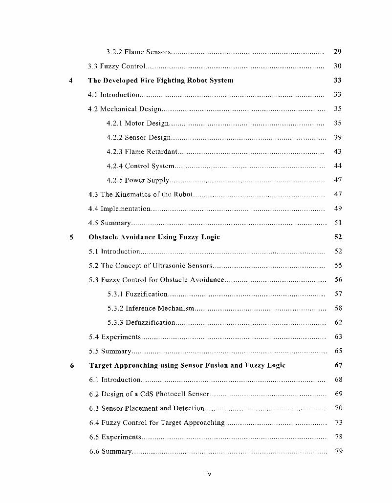
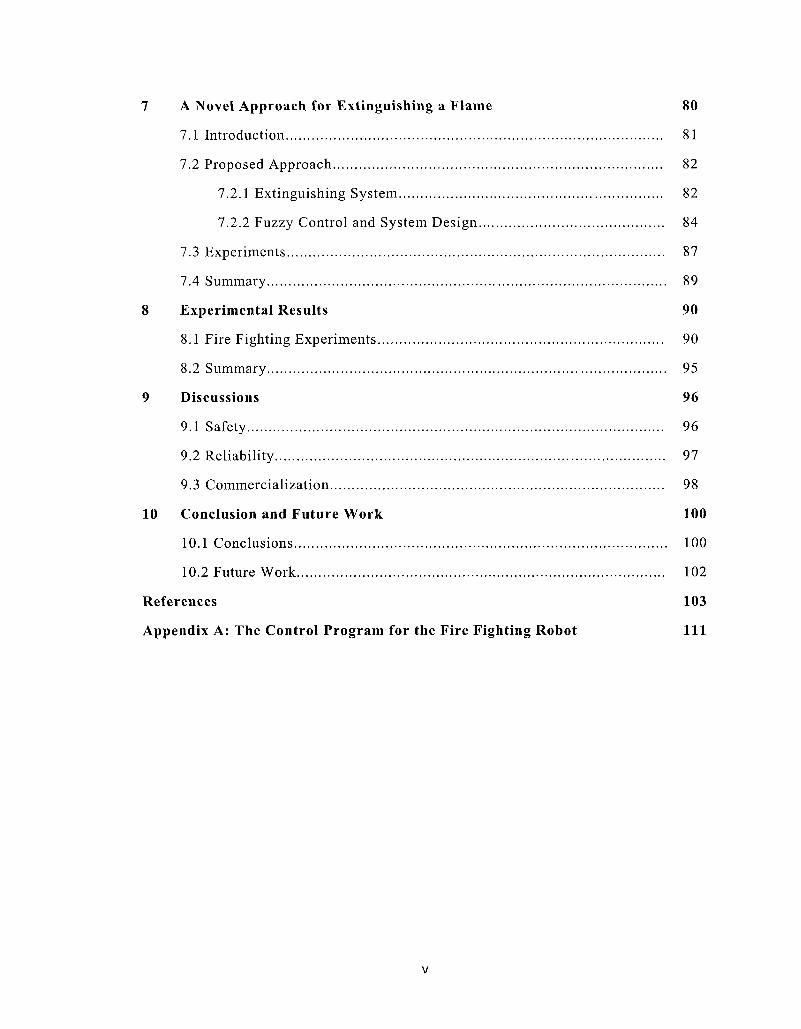