Embed Size (px)
Citation preview

Journal of Electrical and Electronic Engineering 2018; 6(1): 31-39
http://www.sciencepublishinggroup.com/j/jeee
doi: 10.11648/j.jeee.20180601.16
ISSN: 2329-1613 (Print); ISSN: 2329-1605 (Online)
Design and Implementation of Sensorless Electronic Water Pump for Automobile
Junliang Han1, 2, 3
, Hui Song4, Changhong Feng
2, Xiangqing Zhou
2, Chuansheng Tang
1,
Zhengyong Duan1, Jinfeng Gao
3
1Shool of Mechanical and Automotive Engineering, Nanyang Institute of Technology, Nanyang, China 2Henan Province Xixia Automobile Water Pump Co., Ltd., Xixia, China 3College of Electrical Engineering, Zhengzhou University, Zhengzhou, China 4Department of Central Air-conditioning, Midea Group Co., Ltd., Foshan, China
Email address:
To cite this article: Junliang Han, Hui Song, Changhong Feng, Xiangqing Zhou, Chuansheng Tang, Zhengyong Duan, Jinfeng Gao. Design and Implementation of
Sensorless Electronic Water Pump for Automobile. Journal of Electrical and Electronic Engineering. Vol. 6, No. 1, 2018, pp. 31-39.
doi: 10.11648/j.jeee.20180601.16
Received: January 22, 2018; Accepted: March 6, 2018; Published: March 9, 2018
Abstract: The electronic water pump will be used more and more widely in the new energy vehicles and other special vehicles.
A sensorless electronic water pump for automobile is designed and implemented with the brushless direct current motor
(BLDCM) as the driving motor. A sensorless magnetic field oriented control (FOC) scheme using sliding mode observer (SMO)
is applied for the motor control. A novel SMO and the phase-locked loop (PLL) for reducing the chattering phenomenon are used
to estimate rotor velocity/position from the back electromotive force (EMF), in which a continuous saturation function is applied
instead of the sign function. A robust I-f startup strategy is introduced. The hardware circuit design and software algorithm design
are presented. The experimental system is set up and some experimental results are demonstrated. The effectiveness and
correctness of the proposed hardware design and the software scheme are validated. Experimental results show that the
developed electronic water pump is reasonable and feasible with a high cost performance.
Keywords: Electronic Water Pump, Brushless DC Motor, Field Oriented Control, Sliding Mode Observer,
Phase-Locked Loop
1. Introduction
The new energy vehicles and other special vehicles use the
micro water pumps for water circulation, cooling or the water
supply system. The electronic water pump will be used more
and more widely relative to the traditional mechanical water
pump with the characteristics of flexible control, energy
saving and convenient usage. The electronic water pump is
driven with the electric motor. The BLDC motor (BLDCM)
has the advantages with simple structure, no commutation
spark, reliable operation, easy maintenance and so on. These
motors can provide high-power density, high efficiency and
torque to inertia ratio when compared with DC and induction
motors. However, the high performance for BLDCM needs
the accurate rotor position information. But the position
sensors require the additional mounting space, and could
increase the cost and degrade the reliability in harsh
environments. Thus the reduction of sensors is desirable to
reduce cost, simplify hardware and increase reliability [1].
The BLDCM with the back EMF similar to sine wave DC
which characteristics can be represented with the surface-
mounted permanent magnet synchronous motor (SPMSM).
Thus this type of BLDCM can be controlled with the method
for the SPMSM. In recent years, many control strategies
aiming at realizing the sensorless control of PMSM are
reported in the literatures [2]-[32]. All these methods can be
mainly classified into two categories: signal injection
techniques and speed observers. The signal injection
techniques offer a satisfying solution both for standstill and
low speed operation, but they require high precision in the

32 Junliang Han et al.: Design and Implementation of Sensorless Electronic Water Pump for Automobile
measure and increase the complexity of the hardware and
software control system. What is more, the signal injection
techniques will bring high-frequency noise which leads to
system performance degradation. Therefore, the speed
observers are widely used in the sensorless control scheme.
Model reference adaptive method [2]-[8] and extended
Kalman filtering method [9]-[12] belong to the scope of
method based on observer. They rely on the accuracy of the
motor model to some extent, which affects the estimation
performance [17]. Sliding model observer (SMO) [15]-[32]
are known to be insensitive to parameter variations and
disturbances, which are suitable for medium speed or high
speed running condition of PMSM. However, the
conventional SMO method suffers the chattering problem
to the discontinuous switching control. A novel SMO method
is adopted in order to weaken the chattering problem and
increase estimation accuracy of rotor position. In this method,
the conventional switch function is replaced by the sigmoid
function [17], [19]. Further, the PLL is used to calculate the
rotor position after the back-EMF is estimated from the novel
SMO [15], [22], [24], [31].
An electronic water pump for automobile is designed and
implemented in the paper. A BLDCM with the back EMF
similar to sine wave DC is used as the driving motor for the
electronic water pump. A sensorless FOC scheme using SMO
scheme for electronic water pump control is presented. A
novel SMO method with PLL is adopted in order to weaken
the chattering problem of conventional SMO and increase
estimation accuracy of rotor position. In this observer, the sign
function in traditional SMO is replaced by the saturation
function. Further, the PLL is used to calculate the rotor
position after the back-EMF has been estimated from the
novel SMO. The designs of hardware circuit and software
realization algorithm are implemented. The realization of the
presented control algorithm is implemented in the Advanced
RISC Machine (ARM) chip. The experiment system is set up
and the experiments are conducted. The experimental results
show that the aims of high control precision and high stability
are attained. The targets of flow and lift for the electronic
water pump are reached. The effectiveness and correctness of
the proposed hardware design and the sensorless control are
validated.
2. Hardware Design Scheme for
Electronic Water Pump
The hardware circuit of the electronic water pump consists
of power circuit, sampling circuit, communication circuit and
control circuit. The power circuit includes the Electro
Magnetic Compatibility (EMC) circuit, anti-reverse circuit
and 3-phase H Bridge circuit. The function of power
transformation is realized in the power circuit. The sampling
circuit includes the current sampling circuit and temperature
sampling circuit. The communication circuit is composed of
pulse width modulation (PWM) communication circuit, local
interconnect network (LIN) communication circuit, or
Controller Area Network (CAN) communication circuit. The
communication between the electronic water pump and the
vehicle controller unit (VCU) is implemented in the
communication circuit. The control circuit is composed of the
main control chip and its peripheral circuit. Signal processing
and control algorithm are realized in the control circuit.
In the design, a motor control chip of Infineon Corporation
named TLE9879QXA20 is used as the main control chip. It is
a single-chip three-phase motor driver IC, which integrates the
industry standard ARM Cortex M3 kernel. It includes six
fully integrated NFET drivers optimized to drive a 3-phase
motor via six external power NFETs, and a charge pump
enabling low voltage operation and programmable current
along with current slope control for optimized EMC behavior.
Its peripheral set includes a current sensor, a successive
approximation ADC synchronized with the capture and
compare unit for PWM control and 16-bit timers. A LIN
transceiver is also integrated to enable communication to the
device along with a number of general purpose I/Os. It
includes an on-chip linear voltage regulator to supply
external loads.
The communication circuit uses the PWM/LIN
communication mode, which is used for communication
between the electronic water pump and the VCU. The system
block diagram for electronic water pump is shown in Figure 1.
The system includes micro processor uint (MPU), EMC
circuit, anti-reverse circuit, 3-phase H bridge, current
sampling circuit and BLDCM. The anti-reverse circuit adopts
an N type MOSFET as the power switching device. When
working normally, the N type MOSFET operates in
synchronous rectification mode, making the reverse protection
circuit has higher efficiency. The single resistance sampling
scheme is adopted in the current sampling circuit. The bus
current is sampled and then the three-phase current can be
obtained through the algorithm in MPU.
In the process of installation or maintenance of electronic
water pump, if the polarity of power supply is reversed, a large
reverse current will be generated through the internal parasitic
diodes within the power NFETs, which will destroy the
controller and vehicle power in severe cases. So an
anti-reverse circuit is very necessary for electronic water
pump.
Figure 1. System block diagram for electronic water pump.

Journal of Electrical and Electronic Engineering 2018; 6(1): 31-39 33
The schematic of the anti-reverse circuit is shown in Figure
2. It includes the capacitor C1, the resistor R1, the diode D1
and D2 and N type MOSFET VT1. The capacitor C1, the
resistor R1, diode D1 and D2 constitute a voltage-doubling
circuit.
Figure 2. Schematic of the anti-reverse circuit.
During the normal operation, the VCP pin of
TLE9879QXA20 drives voltage-doubling circuit with the
continuous high-frequency square wave signals. Then the
output doubled voltage drives the N type MOSFET VT1,
making VT1 in synchronous rectifier conduction mode. Thus
the power loss produced this circuit is much less than that by
using diode as the power switch device. If the polarity of the
power supply is reversed, due to the role of pull-down resistor
R1, the N type MOSFET VT1 is shut off, and the power circuit
is disconnected. Thus the entire system of electronic water
pump is powered off and the anti-reverse protection function
is realized.
3. Sensorless Control Scheme for
Electronic Water Pump
The sensorless control scheme is based on FOC and I-f
startup strategy. It includes two sequence steps. The first step
is the I-f startup and the second step is the sensorless FOC
working using the novel SMO and PLL.
3.1. Field Oriented Control
Sensorless control scheme for electronic water pump is
demonstrated in Figure 3. The basic idea of FOC is to
synchronize permanent magnets by vector transformation.
The excitation current component (d axis component) and the
torque current component (q axis component) are controlled
respectively, so that the permanent magnet synchronous
motors have the same control characteristics as the DC
motors.
Figure 3. Sensorless control scheme for electronic water pump.
The FOC control algorithm consists of PI controllers,
SVPWM transformation and position/speed estimator. The PI
controllers include the outer speed closed-loop controller and
the inner current closed-loop controllers. The first PI
controller is used for the closed-loop speed control. The
second PI controller is used for the control of q-axis
component Iq. And the third PI controllers is used for the
control of d-axis component Id. The d-axis component Id and
the q-axis component Iq can be obtained through the Clark
transformation and the Park transformation from the
three-phase currents. The sliding mode state observer and the
Phase-Locked Loop constitute the position/speed estimator,
which are used to estimate the position angle of the rotor and
the rotation speed of the motor.
3.2. Novel Sliding Mode Observer
The characteristics of BLDCM with back-EMF similar to
sine wave can be represented with the SPMSM. The
mathematical model of SPMSM is described in d-q
synchronous rotating frame as follows
0-
-
d ds s e s
e fq qe s s s
v iR sL L
v iL R sL
ωωω
+ = + Ψ+
(1)
where dv , qv are the d and q axis voltages; di , qi are the d

34 Junliang Han et al.: Design and Implementation of Sensorless Electronic Water Pump for Automobile
and q axis currents, and sR is the phase winding resistance;
sL is the phase inductance, here s d qL L L= = , and dL , q
L
are the d and q axis inductances; eω is the rotating speed of
magnet flux; fΨ is the permanent magnet flux linkage.
The mathematical model of SPMSM in α-β coordinate
frame can be expressed as the following equation
1 1- -
1 1- -
S
S S S
S
S S S
di Ri v e
dt L L L
di Ri v e
dt L L L
αα α α
ββ β β
= + = +
(2)
where vα , vβ are the α and β axis voltages; iα , iβ are the α
and β axis currents; eα , eβ are the α and β axis back-EMF,
and they can be written as follows
- sin
cos
e f e
e f e
e
e
α
β
ω θω θ
= Ψ = Ψ
(3)
where e
θ is the electric angle.
The schematic diagram of the novel SMO proposed in the
paper is shown in Figure 4. It consists of a sliding mode
current observer, a saturation function, and a low-pass filter.
The saturation function is defined as follows
0 0
0
0
;
( ) ;
;
k x x x x
F x A x x
A x x
⋅ − ≤ ≤= >− < −
(4)
Figure 4. Schematic diagram of the novel SMO.
The low-pass filter adopts one-order low-pass filter, which
can be represented in the frequency domain as follows
( ) ( )c
c
Y s X ss
ωω
=+ (5)
where c
ω is the cutting-off frequency of the low-pass filter.
In the observer, the currents iα , iβ in the α and β axis,
voltages vα , vβ
in the α and β axis are the input variables.
And the estimated back-EMF eα , eβ in the α and β axis are
the output results. The estimated current will be compared
with the actual measured current iα , iβ , then the error
through the saturation function and the low-pass filter will
generate the estimated back-EMF eα , eβ .
The novel sliding mode observer is applied, and the
formulation is shown as follows
ˆ 1 1ˆ ˆ- - ( - )
ˆ 1 1ˆ ˆ- - ( - )
S
S S S
S
S S S
di Ri v F i i
dt L L L
di Ri v F i i
dt L L L
αα α α α
ββ β β β
= +
= +
(6)
where iα , iβ are the estimated current in α and β axis.
From the formula (5) and (6), the dynamic equation of the
estimated current error can be written as
1 1- - ( )
1 1- - ( )
S
S S S
S
S S S
di Ri v F i
dt L L L
di Ri v F i
dt L L L
αα α α
ββ β α
= + = +
(7)
where ˆ= -i i iα α α , ˆ= -i i iβ β β , here iα and iβ are defined as
estimation errors. The stability condition of the sliding mode
observer is as follows
0, 0d d
i i i idt dt
α α β β× < × < (8)
Then from the formula (7), it can be obtained that
2
2
[- ( - ( ))] /
[- ( - ( ))] /
S S
S S
dii R i i v F i L
dt
dii R i i v F i L
dt
αα α α α α
ββ β β β β
× = + × × = + ×
(9)

Journal of Electrical and Electronic Engineering 2018; 6(1): 31-39 35
If the following formulas are adopted,
ˆ( - ) ( )
ˆ( - ) ( )
e F i i F i
e F i i F i
α α α α
β β β β
= =
= = (10)
Thus stability condition formula (8) can be satisfied.
Therefore, the following equations can be obtained
=0 =0didi
dt dt
βα, (11)
In the steady-state condition, the following results can be
obtained
=0 =0i iβ, (12)
That is
ˆ ˆ= =i i i iα α β β, (13)
The PLL is used to estimate the rotor position after the
back-EMF has been estimated. The schematic diagram of the
PLL is shown in Figure 5. The estimated back-EMF eα , eβ
are the input variables. The estimated rotating speed ˆeω and
electric angle ˆe
θ are the output results. In Figure 5, KP is the
Proportion coefficient, and KI is the Integral coefficient of PI
controller, and p is the polar pairs of the motor.
Figure 5. Schematic diagram of the Phase-Locked Loop.
The input error of PI controller can be written as
ˆ ˆˆ ˆ- cos( ) - sin( )e e
e eα βε θ θ= (14)
Then the output of PI controller can be written as
ˆe P I
K K dtω ε ε= + ∫ (15)
Through the PI control, the input error ε will approach to
zero in the steady state, that is
ˆ ˆˆ ˆ- cos( ) - sin( )=0e e
e eα βθ θ (16)
Then the estimated electric angle ˆeθ can be obtained as
follows
1 ˆˆ=- tanˆ
e
e
α
β
θ − (17)
The low pass filter has a phase delay, and the angle of the
electric angle ˆeθ
should be compensated. The compensated
angle is as follows
-1tan ee
c
ωθω
∆ = (18)
3.3. I-f Startup Strategy
Although BEMF theory performs dynamic response from
middle to high speed region very well, it is also limited by too
low BEMF at standstill and low speed. How to start PMSM
from standstill is a challenge. The startup procedure should
also be robust and able to work with different load situations
to ensure that the drive is able to accelerate to a speed at which
the back-EMF is high enough to be accurately sensed. A
simple startup method could be to give dc bias currents to the
phase windings at the beginning in order to align the rotor to a
predetermined position [34]. A smooth transition strategy is
adopted in the paper, which performs well under disturbance,
high efficiency and without parameter requirement. I-f startup
strategy consists of three stages, and they can be expressed as
follows [24], [33]-[35].
Stage 1: Speed ramp-up with constant q-axis current at
initial start. The purpose of this step is to accelerate the motor
from standstill to a desired speed. This step aims to allow the
back-EMF signal can be sensed properly to obtain the accurate
rotor position and speed information. The q-axis current
command and angular frequency command are set separately
as follows
_ 0( )q ref qi t I= (19)
_ ( )e ref et K tω = (20)
where 0qI is a constant current,
eK is a speed coefficient.
Stage 2: Constant speed reference with decreasing q-axis
current at t1. An effective way to offer a smooth transition is to
keep the speed constant while reducing the q-axis current. The
current will approach to the value that will be generated in the
FOC mode, and the rotor d-axis current will be reduced to zero.
The current and torque ripples during the switching to the
FOC mode will then be reduced. The q-axis current command
and angular frequency command are set separately as follows
_ 0 1( ) - ( - )q ref q ii t I K t t= (21)
_ 1( ) ( )e ref et tω ω= (22)
where Ki is a current coefficient.
Stage 3: Switching to the sensorless FOC mode operation at
the end of the stage 2. At this stage, FOC is switched in at the
end of Stage 2 when the estimated rotor position is accurate
36 Junliang Han et al.: Design and Implementation of Sensorless Electronic Water Pump for Automobile
enough. The FOC takes over the control and the q-axis current
command is then determined by the speed control loop to
further regulate the rotor speed [34].
The startup procedure is based on closed-loop current
regulation. It can work under different load conditions and
allows smooth transition from the startup procedure to the
sensorless control mode.
4. Experimental Results
A sensorless electronic water pump for automobile is
developed. The hardware circuit construction is completed
and the sensorless control scheme and other algorithms are
implemented in TLE9879QXA20 with the software codes. The
experiment system is set up and the experiments are
conducted. The physical picture of the developed electronic
water pump is shown in Figure 6. It includes a BLDCM, the
circuit board, connection terminal, motor end cover, pump
impeller, impeller end cover and seal ring. The back-EMF
coefficient of BLDCM is 1.27mV/rpm, and the polar pairs of
the motor are 2 pairs. The inductance of the stator winding is
250µH, and the internal resistance of the stator winding is
0.2Ω. The rated voltage of the BLDCM is 12V, and the rated
power is 60W. The rated speed is set to 4600 r/min.
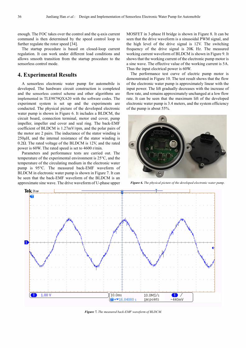
Parameters and performance tests are carried out. The
temperature of the experimental environment is 25°C, and the
temperature of the circulating medium in the electronic water
pump is 95°C. The measured back-EMF waveform of
BLDCM in electronic water pump is shown in Figure 7. It can
be seen that the back-EMF waveform of the BLDCM is an
approximate sine wave. The drive waveform of U-phase upper
MOSFET in 3-phase H bridge is shown in Figure 8. It can be
seen that the drive waveform is a sinusoidal PWM signal, and
the high level of the drive signal is 12V. The switching
frequency of the drive signal is 20K Hz. The measured
working current waveform of BLDCM is shown in Figure 9. It
shows that the working current of the electronic pump motor is
a sine wave. The effective value of the working current is 5A.
Thus the input electrical power is 60W.
The performance test curve of electric pump motor is
demonstrated in Figure 10. The test result shows that the flow
of the electronic water pump is approximately linear with the
input power. The lift gradually decreases with the increase of
flow rate, and remains approximately unchanged at a low flow
rate. It can be seen that the maximum lift of the developed
electronic water pump is 3.4 meters, and the system efficiency
of the pump is about 55%.
Figure 6. The physical picture of the developed electronic water pump.
Figure 7. The measured back-EMF waveform of BLDCM.

Journal of Electrical and Electronic Engineering 2018; 6(1): 31-39 37
Figure 8. The drive waveform of U-phase upper MOSFET in 3-phase H bridge.
Figure 9. The measured line current waveform of BLDCM.

38 Junliang Han et al.: Design and Implementation of Sensorless Electronic Water Pump for Automobile
Figure 10. The performance test curve of electronic water pump.
5. Conclusion
A sensorless electronic water pump for automobile is
designed and implemented in the paper. A novel sliding mode
observer and Phase-Locked Loop are used in sensorless
magnetic field oriented control. A robust I-f startup strategy is
used to guarantee a smooth transition from standstill to FOC
mode. The introduced observer method can effectively
reduce the sliding mode chattering and improve the position
estimation precision. At the same time it preserves the robust
estimation performance and low sensitivity to the variation of
the motor parameters. The feasibility and effectiveness of
rotor position detection technique based on SMO and PLL are
verified by the experimental results. The aims of high control
precision and high stability are attained. The targets of flow
and lift for the electronic water pump are reached. The
effectiveness and correctness of the proposed hardware design
and the sensorless control are validated.
Acknowledgements
This work is supported by two of the Key Scientific
Research Projects in Colleges and Universities of Henan
province (No. 17A470003 and No. 17A150041), and one of
the Major Science and Technology Special Projects in Henan
province (No. 161100210700), as well as a Research Project
“Research on the key technology of variable frequency air
conditioning for new energy vehicles” of Henan provincial
Science and Technology Department in 2018. We thank
team members for their support and contributions to this
study.
References
[1] Taeyeon Kim, Chungil Kim, Joon Lyou. A New Sensorless Drive Scheme for a BLDC Motor Based on the Terminal Voltage Difference. 2011 37th Annual Conference on IEEE Industrial Electronics Society (IECON), pp. 1710-1715, 2011.
[2] E. Babaei, M. B. Bannae Sharifian, R. Ajabi Farshbaf, S. H.
Hosseini. Verification of a New Method for PI Block Design of MRAS-Based Sensorless Speed Estimators. 2011 International Conference on Electrical Machines and Systems (ICEMS), pp. 1-6, 2011.
[3] Pradeep Kumar, Naveen Kaushik, Surender Dahiya. Simulation of Sensor less Speed Control of PMSM based on FOC Method with MRAS Adaptive Speed Estimator. 2013 Annual IEEE India Conference (INDICON), pp. 1-5, 2013.
[4] Nisha G. K., Lakaparampil Z. V., Member, IEEE and Ushakumari S. Four-quadrant Operation of Sensorless FOC Induction Machine in Field Weakening Region Using MRAS-Sliding Mode Observer. 2013 International Conference on Control Communication and Computing (ICCC), pp. 33-38, 2013.
[5] Sandeep Dhundhara, Pradeep Kumar, Yajvender Pal Verma. Sensorless Speed Control of PMSM Using Space Vector Pulse Width Modulation Based on MRAS Method. 2015 2nd International Conference on Recent Advances in Engineering & Computational Sciences (RAECS), pp. 1-6, 2015.
[6] Naggar H. Saad, Ahmed A. El-Sattar, Mahmoud A. Gad. Sensorless Field Oriented Control Based on Improved MRAS Speed Observer for Permanent Magnet Synchronous Motor Drive. 2016 Eighteenth International Middle East Power Systems Conference (MEPCON), pp. 991-998, 2016.
[7] Bernadeta Wuri Harini, Aries Subiantoro, Feri Yusivar. Stability Analysis of MRAS Speed Sensorless Control of Permanent Magnet Synchronous Motor. 2017 International Conference on Sustainable Energy Engineering and Application (ICSEEA), pp. 34-40, 2017.
[8] Karthikeyan A, Prabhakaran K K, Venkatesa Perumal B, Nagamani C. Pseudo Derivative Feedback current controlled sensorless PMSM drive with Flux-Torque based MRAS estimator for low speed operation. 2017 IEEE International Symposium on Sensorless Control for Electrical Drives (SLED), pp. 115-120, 2017.
[9] Tang Ming, Gao Lin, and Liang Deliang. Sensorless Permanent Magnet Synchronous Motor Drive Using an Optimized and Normalized Extended Kalman Filter. 2011 International Conference on Electrical Machines and Systems, pp. 1-4, 2011.
[10] Nguyen K. Quang, Doan Duc Tung, Q. P. Ha. FPGA-Based Sensorless PMSM Speed Control using Adaptive Extended Kalman Filter. 2015 IEEE International Conference on Automation Science and Engineering (CASE), pp. 1650-1655, 2015.
[11] Tomasz Michalski, Carlos Lopez, Antoni Garcia, Luis Romeral. Sensorless Control of Five Phase PMSM Based on Extended Kalman Filter. 2016 42nd Annual Conference of the IEEE Industrial Electronics Society (IECON), pp. 2904-2909, 2016.
[12] Mohamad Syakir Termizi, Jurifa Mat Lazi, Zulkifilie Ibrahim, Md Hairul Nizam Talib, M. J. A. Aziz, S. M. Ayob. Sensorless PMSM drives using Extended Kalman Filter (EKF). 2017 IEEE Conference on Energy Conversion (CENCON), pp. 145-150, 2017.
[13] Rui Gao, Iqbal Husain, Jianyong Su. “An Improved Rotor Flux Estimation Strategy for Position-sensorless Control of Surface-mount Permanent Magnet Synchronous Motor,” 2014 40th Annual Conference of the IEEE Industrial Electronics Society (IECON), pp. 404-409, 2014.

Journal of Electrical and Electronic Engineering 2018; 6(1): 31-39 39
[14] Guoliang Xiao, Xiaoguang Wang, Wenyi Tu, Lixun Tang, Huan Zhang, Kai Yang. A Sensorless Control of Surface-mount Permanent Magnet Synchronous Motor Based on Rotor Flux Estimation. 2017 20th International Conference on Electrical Machines and Systems (ICEMS), pp. 1-4, 2017.
[15] Ran Li, Guangzhou Zhao. Position Sensorless Control for PMSM Using Sliding Mode Observer and Phase-Locked Loop. Proceedings of the IEEE 6th International Power Electronics and Motion Control Conference, pp. 1867-1870, 2009.
[16] Justin Owen, Jeff Strouse. Sensorless Field Oriented Control Utilizing a Sliding Mode Observer for Control of an Actively- Rectified Permanent Magnet Synchronous Generator. 2011 Twenty-Sixth Annual IEEE Applied Power Electronics Conference and Exposition (APEC), pp. 1017-1021, 2011.
[17] Zhaowei Qiao, Tingna Shi, Yindong Wang, Yan Yan, Changliang Xia, Xiangning He. New Sliding-Mode Observer for Position Sensorless Control of Permanent-Magnet Synchronous Motor. IEEE Transactions on Industrial Electronics, vo1. 60, no. 2, pp. 710-719, 2013.
[18] Bing Liu, Bo Zhou, Haidong Liu, Jie Li, Long Wang, Qinglong Wang. Research on Initial Rotor Position Estimation for SPMSM. 2014 17th International Conference on Electrical Machine and Systems (ICEM), pp. 768-774, 2014.
[19] Saadaoui, A. Khlaief, M. Abassi, A. Chaari, M. Boussak. Position Sensorless Vector Control of PMSM Drives Based on SMO. 2015 16th international conference on Sciences and Techniques of Automatic control & computer engineering, pp. 545-550, 2015.
[20] Vasilios C. Ilioudis. Chattering reduction applied in PMSM sensorless control using Second Order Sliding Mode observer. 2015 9th International Conference on Compatibility and Power Electronics (CPE), pp. 240-245, 2015.
[21] Hanan Mikhael Dawood Habbi, Afaneen Anwer Abood Al-Khazraji. FPGA based vector control of PM motor using sliding mode observer. 2015 Modern Electric Power Systems (MEPS), pp. 1-5, 2015. 2015 27th Chinese Control and Decision Conference (CCDC), pp. 6091-6096, 2015.
[22] Lisi Tian, Yang Liu, Jin Zhao, Jiajiang Sun. The sensorless control of IPMSM based on improved sliding-mode observer. 2015 27th Chinese Control and Decision Conference (CCDC), pp. 935-940, 2015.
[23] Saadaoui, A. Khlaief, M. Abassi, A. Chaari, M. Boussak. Sensorless FOC of PMSM drives based on Full Order SMO. 2017 17th international conference on Sciences and Techniques of Automatic control & computer engineering, pp. 663-668, 2016.
[24] Ying-Shieh Kung,Risfendra,Yi-De Lin,and Liang-Chiao Huang. FPGA-Based Sensorless Controller for PMSM Drives Using Sliding Mode Observer and Phase Locked Loop. 2016
International Conference on Applied System Innovation (ICASI), pp. 1-4, 2016.
[25] Donglai Liang, Jian Li, Ronghai Qu. Super-twisting algorithm based sliding-mode observer with online parameter estimation for sensorless control of permanent magnet synchronous machine. 2016 IEEE Energy Conversion Congress and Exposition (ECCE), pp. 1-8, 2016.
[26] Mihai Comanescu. Speed, rotor position and load torque estimation of the PMSM using an extended dynamic model and cascaded sliding mode observers. 2016 International Symposium on Power Electronics, Electrical Drives, Automation and Motion (SPEEDAM), pp. 98-3, 2016.
[27] Hrishikesh Mehta, Vrunda Joshi, Pradeep Kurulkar. Implementation issues of sliding mode observer for sensorless field oriented control of PMSM using TMS320F2812. 2016 IEEE Symposium on Sensorless Control for Electrical Drives (SLED). pp. 1-6, 2016.
[28] Guozheng Li, Bo Zhang. Sensorless control of PMSM using Chua's circuit based on sliding mode observer. 2016 IEEE 8th International Power Electronics and Motion Control Conference (IPEMC-ECCE Asia), pp. 1840-1846, 2016.
[29] Chuanchuan Lin; Hong Guo; Shuping Meng; Xiaofeng Ding. Sensorless Control of PMSM Based on Modified Sliding Mode Observer. 2016 IEEE Vehicle Power and Propulsion Conference (VPPC), pp. 1-5, 2016.
[30] Vasillos C. Ilioudis. A model based sliding mode observer applied in PMSM sensorless control for speed and position. 2017 25th Mediterranean Conference on Control and Automation (MED), pp. 921-926, 2017.
[31] Yanling Yang, Hong Guo, Hao Qian. A sensorless control of SPMSM based on sliding mode observer with linear power drive method. 2017 43rd Annual Conference of the IEEE Industrial Electronics Society (IECON), pp. 4094-4098, 2017.
[32] Ons Ben Hamouda; Adel Khedher. PMSM under IOLC introducing a sliding mode position and speed observer. 2017 International Conference on Green Energy Conversion Systems (GECS), pp. 1-6, 2017.
[33] Wenjie Wang, Zexiang Li, Xiang Xu. A Novel Smooth Transition Strategy for BEMF-Based Drive Startup of PMSM. Proceedings of 11th World Congress on Intelligent Control and Automation (WCICA), pp. 4296-4301, 2014.
[34] Z. Wang, K. Lu and F. Blaabjerg, A Simple Startup Strategy Based on Current Regulation for Back-EMF-Based Sensorless Control of PMSM, IEEE Transactions on Power Electronics, vol. 27, no. 8, pp. 3817-3825, 2012.
[35] Li Niu, Jianyang Zhai, Xiong Liu, Youyi Wang, Amit Kumar Gupta. A Smooth and Fast Transition Method for PMSM SMO Based Sensorless Control. 2016 IEEE 2nd Annual Southern Power Electronics Conference (SPEC), pp. 1-6, 2016.