Embed Size (px)
Citation preview
Calhoun: The NPS Institutional Archive
Theses and Dissertations Thesis Collection
1983
Design and implementation of software protocol in
VAX/VMS using ethernet local area network.
Netniyom, Thawip P.
Monterey, California. Naval Postgraduate School
http://hdl.handle.net/10945/19729


Dudley Knox Library. NPS
Monterey. CA 93943


NAVAL POSTGRADUATE SCHOOL
Monterey, California
THESISDESIGN AND IMPLEMENTATION
OF SOFTWARE PROTOCOL IN VAX/VMSUSING ETHERNET LOCAL AREA NETWORK
by
Thawip P. NetniyomJune 1983
Thesis Advisor: U . R . Kodres
Approved for public release; distribution unlimited
T210147

Dudley Knox Library, NPSMonterey, CA 93943
SECURITY CLASSIFICATION OF THIS PAGE (Whan Data ISntarad)
REPORT DOCUMENTATION PAGE READ INSTRUCTIONSBEFORE COMPLETING FORM
1. REPORT NUMBER 2. GOVT ACCESSION NO. 3. RECIPIENT'S CATALOG NUMBER
4. TITLE and Subtttta)
Design and Implementation of SoftwareProtocol in VAX/VMS Using EthernetLocal Area Network
5. TYPE OF REPORT & PERIOD COVERED
Master ' s Thes isJune 1983
6. PERFORMING ORG. REPORT NUMBER
7. authors;
Thawip P. Netniyom
8. CONTRACT OR GRANT NUMBERC*)
9 PERFORMING ORGANIZATION NAME AND AOORESS
Naval Postgraduate SchoolMonterey, California 93940
10. PROGRAM ELEMENT. PROJECT, TASKAREA ft WORK UNIT NUMBERS
11. CONTROLLING OFFICE NAME AND AOORESS
Naval Postgraduate SchoolMonterey, California 93940
12. REPORT DATE
June 198313. NUMBER OF PAGES
11814. MONITORING AGENCY NAME ft AOORESSfif dlllarant /rem Controlling Otllca) 15. SECURITY CLASS, (ol thla report)
Unc lassif ied
!5«. DECLASSIFICATION/ DOWNGRADINGSCHEDULE
16. DISTRIBUTION STATEMENT (of thla Import)
Approved for Public Release; Distribution Unlimited
17. DISTRIBUTION STATEMENT (ol tha aoarract antarad In Block 20. It illlarant from Raport)
It. SUPPLEMENTARY NOTES
19. KEY WOROS (Continue on ravataa oldo It nocoaaary and Idantlty by block numbar)
Ethernet, Unibus, Multibus, Network, Protocol HierarchiesDECnet, ISO Reference Model
20. ABSTRACT (Contlnuo on rovatao aldm It nacaaaarv and Idantlty by block numbar)
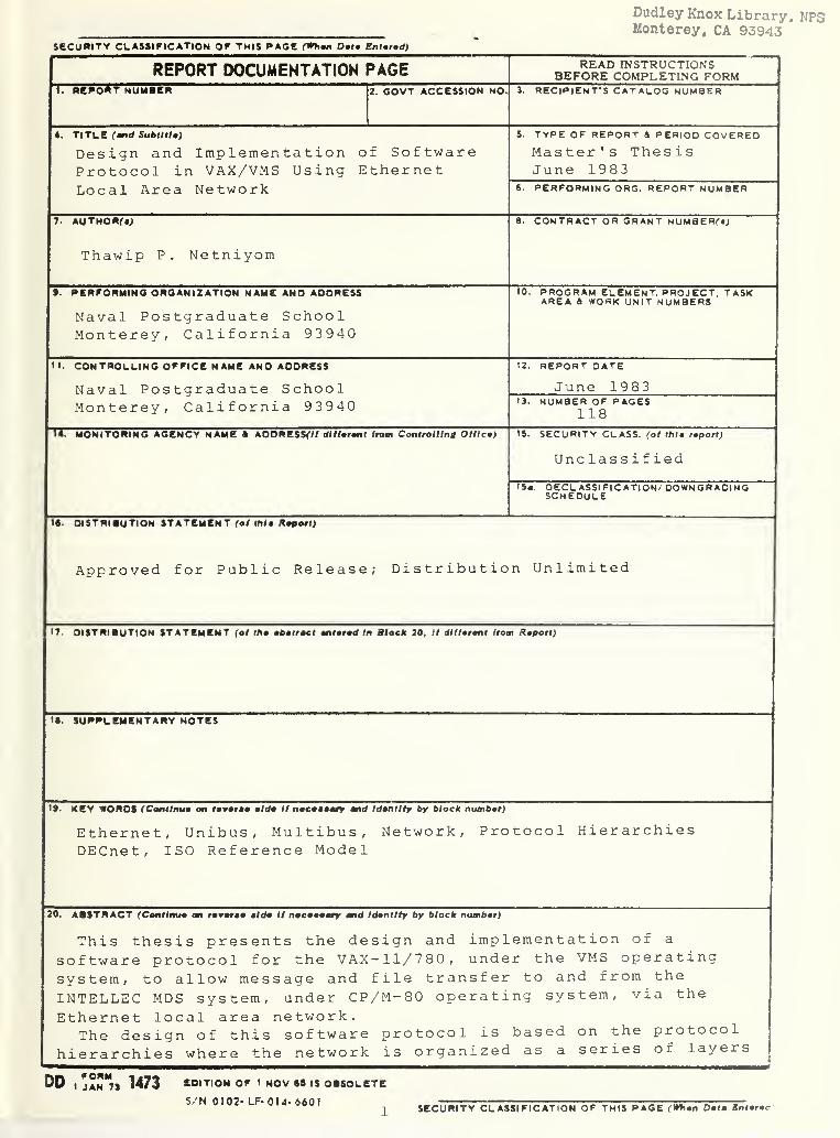
This thesis presents the design and implementation of a
software protocol for the VAX-11/780, under the VMS operatingsystem, to allow message and file transfer to and from the
INTELLEC MDS system, under CP/M-80 operating system, via the
Ethernet local area network.The design of this software protocol is based on the protoco
hierarchies where the network is organized as a series of laye1
r s
DD, K"7, 1473 EDITION OF 1 NOV «S IS OBSOLETE
S/N 0102- LF- 014- 6601 SECURITY CLASSIFICATION OF THIS PAGE (Whan Data Bntarac


SECURITY CLASSIFICATION OF THIS PAGE (Whmn Dmtm Enffd)
or levels, each one build upon its predecessor. The purpose ofeach layer is to offer certain services to the higher layers,shielding those layers from the details of how the offeredservices are actually implemented.
With this design concept, the desired software protocol willbe transportable in the sense that it can be used by differentcomputer systems with minimal modifications.
The Ethernet local area network is also designed in thissame highly structured way.
SN 0102- LF- 014- 6601
2 SECURITY CLASSIFICATION OF THIS PAGEfWh»n Datm Enturmd)


Approved for public release; distribution unlimited
Design and Implementationof Software Protocol in VAX/VMS
Using Ethernet Local Area Network
by
lhawip P. NetniyomSecond Lieutenant ,'' Royal Thai Army
B.S. , Philippine Military Academy, 1981
Submitted in partial fulfillment of therequirements for the degree of
MASTER OF SCIENCE IN COMPUTER SCIENCE
from the
NAVAL POSTGRADUATE SCHOOLJune 1983


ABSTRACT
This thesis presents the design and implementation of a
software protocol for the VAX-1 1/780, under the VMS oper-
ating system, to allow message and file transfer to and from
the INTELISC MDS system, under CP/fi-80 operating system, via
the Ethernet local area network.
The design of this software protocol is based on the
protocol hierarchies where the network is organized as a
series of layers or levels, each one build upon its prede-
cessor. The purpose of each layer is to offer certain
services to the higher layers, shielding those layers from
the details of hew the offered services are actually
implemented.
With this design concept, the desired software protocol
will be transportable in the sense that it can be used by
different kinds of computer systems with minimal
modifications.
The Ethernet local area network is also designed in this
same highly structured way.


TABLE CF CONTENTS
I. INTRODUCTION 9
a. DISCLAIMER 9
B. GENERAL DISCUSSION 9
C. E AC K GROUND 10
D. STRUCTURE CF THE THESIS 11
II. EASIC DESIGN CONCEPTS 13
A. PROTOCOL FOR LOCAL AREA NETWORK 13
1. Background 13
2. Application subsystem perspective of
elementary protocols 16
E. PROTOCOL HIERARCHIES 20
C. DESIGN ISSUES FOR THE LAYERS 22
D. THE ISO REFERENCE MODEL 24
III. ETHERNET LOCAL AREA NETWORK 30
A. OVERVIEW 30
B. CONCISE ETHERNET SPECIFICATION 31
1. Packet Format 31
2. Centre! Procedure 33
3. Channel Encoding 34
4. Data Rate 35
5. Carrier 35
6. Coax Cable 35
7. Coax Connectors and Terminators 36
8. Transceiver 37
C. NI1010 UNIEUS ETHERNET COMMUNICATIONS
CCNTROLLER 37
1. Features 37


2. Description 38
3. Ethernet data link layer functions .... 38
4. Ethernet physical layer functions . . . . 43
5. Performance 44
6. Extensive Diagnostic Features 44
7. Network statistics 45
IV. DETAILED DESIGN AND IMPLEMENTATION 47
A. DESIGN ISSUES CONSIDERATION 47
E. NS2030 DEVICE DRIVER 48
1. Overview 48
2. Program interfaces to NIDRIVER 50
C. DESIGNING EROCEDURE 5 8
1. Steps in developing the application layer 59
2. Method to Overcome Frame Sequencing ... 60
D. I IMPLEMENTATION 62
V. CONCLUSION 63
APPENDIX A: VAX/VMS SYSTEM SERVICE ROUTINES 67
APPENDIX E: SOURCE CCDE FOR EXPERIMENTS 81
APPENDIX C: ETHERNET SOFTWARE PROTOCOL SOURCE CODE ... 93
APPENDIX D: VAX/VMS-MDS ETHERNET LOCAL COMMUNICATION
NETWORK USER MANUAL 106
APPENDIX E: SYMEOLIC NAME FOR NI1010 CONTROLLER COMMAND
CODE 112
APPENDIX I: NID3IVER FUNCTION AND STATUS CODE SUMMARY 114
LIST CF DEFERENCES 116
INITIAL DISTRIBUTION LIST 117


LIST OF TABLES
I- Type Field Protocol: (All in Hexadecimal) 61


LIST OF FIGURES
2.1 Local Area Network Topologies 15
2.2 Layers, Protocols, and Interfaces 21
2.3 ISO Reference Model 24
3.1 Contention, Transmission, and Idle States ... 30
3.2 Ethernet Packet Format 31
3.3 Data Rate Scheme 34
3.4 Coax Cable, Connectors, and Transceivers .... 36
3.5 Ethernet Architecture and Implementation .... 39
3.6 Ethernet Frame Format 40
3.7 NI1010 Functional Diagram 45
4.1 NI1010 and ISO Reference Model 49
4.2 Transmit Packet Format 55
4.3 Beceive Packet Format 56
4.4 Mapping between ISC Model and DECNET 58


I- IO10D0CTI0N
A. DISCLAIMER
Many terms used in this thesis are registered trademarks
of commercial products. Rather than attempt to cite each
individual cccurrence of a trademark, all registered trade-
marks appearing in this thesis will be listed below,
following the firm hclding the trademark:
INTEL Corporation, Santa Clara, California
INTELLEC HDS
Multibus
DIGITAL Research, Pacific Grove, California
CE/M-80
INTERLAN Corporation, Chelmsford, Massachusetts
NI1010 Onifcus Ethernet communications controller
beard
NI30 10 Multibus Ethernet communications controller
board
NS2030 VMS device driver and NI1010 diagnostic
prcgra m
DIGITAL Equipment Corporation, Maynard, Massachusetts
VAX-11/780 Mini computer
VAX/VMS operating system
B. GENERAL DISCOSSICN
This thesis presents the design and implementation of
software protocol for the VAX-11/780, under VMS operating
system, to allow message and file transfer to and from
INTELLEC MDS system, under CP/M-80 operating system, via
Ethernet local area network.

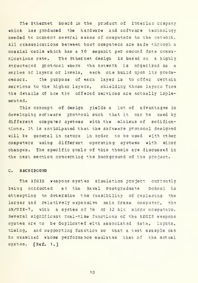
The Ethernet board is the product of Interlan company
which has produced the hardware and software technology
needed tc connect several makes of computers to the network.
All communications between host computers are made through a
coaxial cable which has a 1 megabit per second data commu-
nications rate. The Ethernet design is based on a highly
structured protocol where the network is organized as a
series of layers or levels, each one build upon its prede-
cessor. The purpose of each layer is to offer certain
services to the higher layers, shielding these layers from
the details of hew the offered services are actually imple-
mented.
This concept of design yields a lot of advantages in
developing software protocol such that it can be used by
different computer systems with the minimum of modifica-
tions. It is anticipated that the software protocol designed
will be general in nature in order to be used with ether
computers using different operating systems with minor
changes. The specific goals of this thesis are discussed in
the next section concerning the background of the project.
C. BACKGBCOND
The AEGIS weapons system simulation project currently
being conducted at the Naval Postgraduate School is
attempting to determine the feasibility of replacing the
larger and relatively expensive main frame computer, the
AN/UYK-7, with a system of 16 or 32 bit micro computers.
Several significant real-time functions of the AEGIS weapons
system are to be duplicated with associated data, inputs,
timing, and supporting function so that a test example can
be examined whose performance emulates that of the actual
system. [Ref. 1.]
10


Since the AEGIS weapons system simulation project
involves many micro computers and since all of them mast be
real-time system, the speed of data communications between
any two computers is very crucial. Thus, a high-speed means
of communication is needed.
Ethernet local area network is considered to be the
solution because of its capability of permitting 10 megabit
per second data communications between stations separated by
up to 25C0 meters. Iwo NI3010 Multibus Ethernet communica-
tion controller boards and a NI1Q10 Unibus Ethernet communi-
cation controller beards were purchased and implemented in
INTELIEC MDS systems and VAX-1 1/780, under the VMS operating
system, respectively. An NS2030 device driver and an NI1010
diagnostic program are also implemented in the VAX.
The specific goals of this thesis are:
1.To design and implement software protocol en the
VAX/VMS such that it would be able to communicate (transfer
messages and files) with the INTELLEC MDS system, under the
CP/M operating system.
2. To be used as a guideline in designing software
protocols, especially when there is a need to communicate
between VAX/VMS and ether systems which use different oper-
ating systems such as ISIS- II.
D. STRUCTURE OF THE THESIS
Chapter I presents a general discussion of the larger,
ongoing effort of which this thesis is a part. It also gives
a general discussion of the background work of the AEGIS
weapons system simulation project and the need of the
Ethernet local area network which leads to this thesis
research.
11


Chapter II addresses the overall design philosophy of
the software prctoccl which will be used in the VAX/VMS.
Protocol for a local area network is discussed in detail to
include the relationship to the 130 open system interconnec-
tion model. The design issues for the layers are enumerated
to be a step-by-step guide in designing the protocol.
Chapter III discusses the Ethernet Local Area Network,
concise Ethrnet specification, and the NI1010 Onibus
Ethernet Controller Board.
Chapter IV explains the detailed design of the software
protocol to include the use of the NS2030 Device Driver, how
Ethernet Eoard and the Device Driver take care of the design
issues for the layer mentioned in Chapter II, and steps in
developing the application layer protocol.
Chapter V summarizes the testing of the implemented
software protocol and describe its capabilities. Suggestions
are also given for future research and modification.
12


II. EASIC DESIGN CONCEPTS
A. ERCTCCOL FOR LOCAL AREA NETWORK
1 • Background
A set of protocols specifiss how nodes can communi-
cate ever networks. Protocols ars the procedures and conven-
tions used to regiment the event progression reguired for
orderly, mutually understood interaction between processes.
Protocols are developed to satisfy qualitativa and quantita-
tive reguirements for process interconnection, A primary
gualitative requirement is the "useful" work (i.e., func-
tionally) to be provided by the protocol. Other qualitative
reguirements include:
.flexibility (to accommodate new uses and features)
.completeness (tc properly respond to all relevant
network conditions)
.deadlock avoidance/backout mechanisms
.synchronization mechanisms (for interprocess control)
.error detection and recovery
. tuf f er overflow avoidance
. uessage seguencing assurance
.duplicate message detection and recovery
.permeance (to implement the protocol uniformly through
the local area network)
.priority mechanisms
. accounting mechanisms
13


1). security mechanisms
ra). message delivery guarantees
n).data ccde/fcrmat Transformations
o). computer equipment feature compatibility
p). operating system feature compatibility
q) . communications network feature compatibility
Net all of these requirements are cf equal impor-
tance for each protocol implementation. For example, a
protocol might inhabit a local area network node environment
configured into any of the following topologies or hybrids
of these topologies:
a) .star topology - a centralized topology in which lines
converge to a central point or points (see Figure
2- 1) ;this tcpolcgy is also called hierarchical or tree.
b).mesh topology - nodes are connected in an arbitrary
pattern; each node can have multiple paths to ether
nodes.
c) .ring topology - the communications path is a loop with
each node connected to exactly two ether nodes in a
given loop.
d) .bus topology - the nodes are connected along line
segments; this topology is commonly found in Local area
networks with a shared transmission channel such as a
cable-bus.
Typically, routing protocols for mesh topologies are much
mere complex than routing protocols for the oxher topolo-
gies. Thus, other protocol requirements, such as message
delivery guarantees and message sequencing assurance, may be
influenced by the topology chosen.
14


Figure 2.1 local Area Network Topologies,
Quantitative requirements for protocols include:
a) throughput - the volume of information that must be
transferred during the paak period. This volume is
usually characterized by mean message length in octets,
the distribution of message lengths, and by the arrival
rate cf messages.
15


b) delay - the mean and maximum delay -chat the protocol
will add to process responsiveness during the peak
period.
c) ccst - maximum acceptable recurring and nonrecurring
costs associated with the installation of a protocol in
a local area network.
A protocol may perform functions at the communica-
tion link level or at application process level. Of primary
concern tc lccal area network application developers are the
application level protocols. Some of the protocols which
might be considered elementary to local area network devel-
opments are discussed below.
2 • Application s ubsys tem persp ectiv e of eleme ntar y
protocols
The need fcr a number of elementary high-level
protocols providing various types of services is apparent.
Three main groupings of such protocols may be defined:
appl icaticn-criented , executive-oriented, and network-
induced. The motivation for this classification is the
perspective of distributed systems as extensions of the
single-system environment. The goal of elementary protocols
is to extend the array of system utilities, programs and
operating system services that are available on a single
system to the total lccal area network. Hence, development
of elementary local area network protocols is a basic step
in evolving high-level operating systems for local area
networks.
a. Appl icaticn-Oriented Frotocols
Application-oriented protocols are defined tc be
interprocess communication rules and data formats which
extend the commonly used system programs (languages,
16


editors, library, etc.) of one node to an application
process in another node. Such protocols may include:
1 ) «IiiJ Tra nsfer - allowing a process in one node to
access files on another node as though the process were
executing in that node. Similar to general system util-
ities that support media conversion with and without
blocking changes, format changes, naming changes,
etcetera.
2) • loiter. - allowing a process in one node to store,
modify and retrieve text information in a file at
another node. Preferably the protocol is implemented to
a specification consistently applied at each node on
the network.
3) .Compile - allowing a process in one node to produce
executable programs at another node. The protocol
implements a network wide source and object cede
library and linkage editor.
**) -liiSiJte - allowing a process in one node to invoke a
program at another node by module name, to supply
parameters to the program and to receive program output
and system notice messages at the sending local area
network node process.
5) .Debucj - allowing a process in one node to dynamically
debug a program at another node. Preferably allows an
application process distributed among two or more local
area network nodes to be debugged interactively.
b. Executive-Oriented Protocols
Executive level protocols are defined to be
interprocess communication rules and data formats which
extend the operating system services (resource allocation.
17

device or program service, monitor services, etc.) of one
node to an application process in another node.
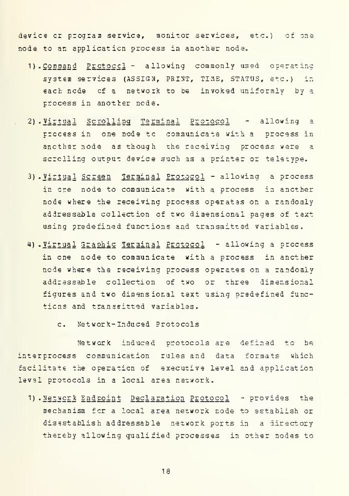
1). Command Prctoccl - allowing commonly used operating
system services (ASSIGN, PRINT, TIME, STATUS, etc.) in
each node of a network to be invoked uniformly by a
process in another node.
2) -Virtual Scrolling Terminal Pr otoco l - allowing a
process in one node to communicate with a process in
another node as though the receiving process were a
scrolling output device such as a printer or teletype.
3) -Virtual Screen Termi nal Protocol - allowing a process
in ore node to communicate with a process in another
node where the receiving process operates on a randomly
addressable collection of two dimensional pages of text
using predefined functions and transmitted variables.
4) -Virtual Graphic Terminal Protocol - allowing a process
in one node to communicate with a process in ancther
node where the receiving process operates on a randomly
addressable collection of two or three dimensional
figures and two dimensional text using predefined func-
tions and transiritted variables.
c. Network-Induced Protocols
Network induced protocols are defined to be
interprocess communication rules and data formats which
facilitate the operation of executive level and application
level protocols in a local area network.
1) «Metggr k Endpoint Decla ration Protocol - provides the
mechanism for a local area network node to establish or
disestablish addressable network ports in a directory
thereby allowing qualified processes in other nodes to
18


become associated with processes assigned to this for*.
The prctoccl might serve normal and previieged
processes in the application space as well as network
control functions within the operating system. This
prctoccl provides a mechanism to identify "well known"
processes in a network directory.
2) . Network A cce ss Autho rization Protocol - allcwing a
process to gain access to another process in the
network. Includes log-on/log-off support to end users
as well as general process interconnection authoriza-
tion. Interfaced with network security and privacy
management information systems.
3) . Network Directory Service Protocol - allowing a process
to request information about a node, another process or
an end user. May also support custom menu services for
each network user to promote the impression of a single
integrated system.
**) Transport Control Protocol - allowing a process in one
node to establish an association with a process in
another node and to exchange messages in a virtual
circuit or datagram mode. Usually implemented as an
augmentation to the operating system of a network node.
5) .Interprocess S ynchronization - providing a mechanism
for two or more processes in two or more nodes to coor-
dinate asynchronously executing functions. This
prctoccl could underlie the virtual terminal control
prctcccl.
6) . Network S yst em Control Protocol - providing the
mechanism for establishing "built-in" maintenance and
security subsystems in a local area network environ-
ment. It is envisioned that performance, maintenance
19


and security checks should permeate the local area
network software as well as hardware system. This
prctcccl facilitates unified specification of perfor-
mance, maintenance and security related functions.
B. PROTOCOL HIERARCHIES
To reduce their design complexity, most networks are
organized as a series of layers or levels as mentioned
earlier.
Layer n on one machine carries en a conversation with
layer n en another machine. The rules and conventions used
in this cenversation are collectively known as the layer n
protocol, as illustrated in Fig. 2.2 for a seven-layer
network. The entities comprising the corresponding layers
on different machines are called peer processes. In ether
words, it is the peer processes that communicate using
protocol.
In reality, no data are directly transferred frcm layer
n on one machine to layer n on another machine (except in
the lowest layer) . Instead, each layer passes data and
control information to the layer immediately below it, until
the lowest layer is reached. At the lowest layer there is
£ll2Jij£li co mmunication wi-ch the other machine, as opposed to
the virtual communication used by the highest layers. In
Fig. 2.2 virtual communication is shown by dotted lines and
physical communication by solid lines.
Between each pair of adjacent layers there is an i nter -
face. The interface defines which primitive operations and
services the lower layer offers to the upper one. When
network designers decide how many layers to include in a
network and what each one should do, one of the most impor-
tant considerations is having cleanly defined intefaces
between the layers. Having cleanly defined interfaces, in
20


Host A
Layer 7
Layer 6/7 interface
Layer 6
Layer 5/6 interface
Layer 5
Layer 4/5 interface
Layer 3/4 interface
Layer 4
T
Layer 3
Layer 2/3 interface
Layer 1/2 interface
Layer 2
T
Layer 1
Layer 7 protocol
Layer 6 protocol
Layer 5 protocol
Layer 4 protocol
Layer 3 protocol
Layer 2 protocol
Layer 1 protocolm »
Host B
Layer 7
1
1
Layer 6
Layer 5
x
Layer 4
Layer 3
X
Layer 2
Layer 1
Figure 2.2 Layers, Protocols, and Interfaces.
turn, requires that each layer perforin a specific collection
cf well ur.derstocd functions. In addition to minimizing the
amount cf information that must be passed between layers,
clean cut interfaces also make it simpler to replace the
implementation of one layer with a completely different cne,
because all that is required of the new implementation is
that it offers exactly the same set of services to its
upstairs neighbor as the old implementation did.
21

The set of layers and protocols is called the ne twor k
achitecture [Ref . 2. ]- The specification of the architec-
ture must contain enough information to allow an impl em enter
to write the program for each layer so that the program will
correctly otey the appropriate protocol. Neither the details
of the implementation nor the specification of the inter-
faces are part of the architecture. In fact, it is not even
necessary that the interfaces on all machines in a network
be the same, provided that each machine can correctly use
all the protocols.
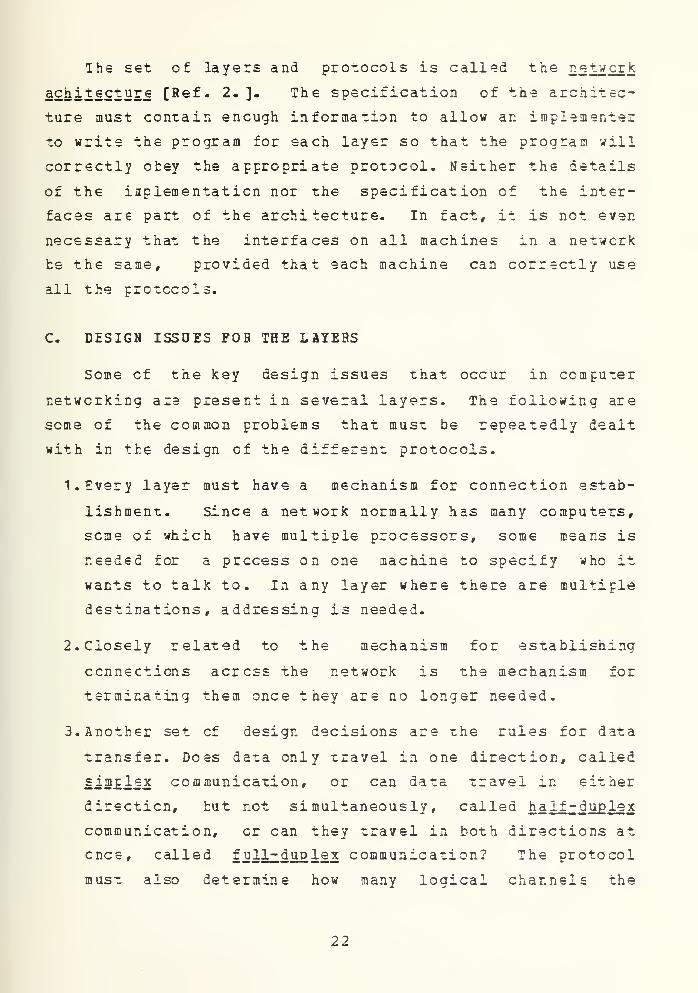
C. DESIGN ISSUES FOB THE LAYERS
Some of the key design issues that occur in computer
networking are present in several layers. The following are
some of the common problems that must be repeatedly dealt
with in the design of the different protocols.
1. Every layer must have a mechanism for connection estab-
lishment. Since a network normally has many computers,
seme of which have multiple processors, some means is
needed for a process on one machine to specify who it
wants to talk to. In any layer where there are multiple
destinations, addressing is needed.
2. Closely related to the mechanism for establishing
connections across the network is the mechanism for
terminating them once they are no longer needed.
3. Another set of design decisions are the rules for data
transfer. Does data only travel in one direction, called
simplex communication, or can data travel in either
direction, but not simultaneously, called half-d uple x
communication, or can they travel in both directions at
ence, called full-dup lex communication? The protocol
must also determine how many logical channels the
22

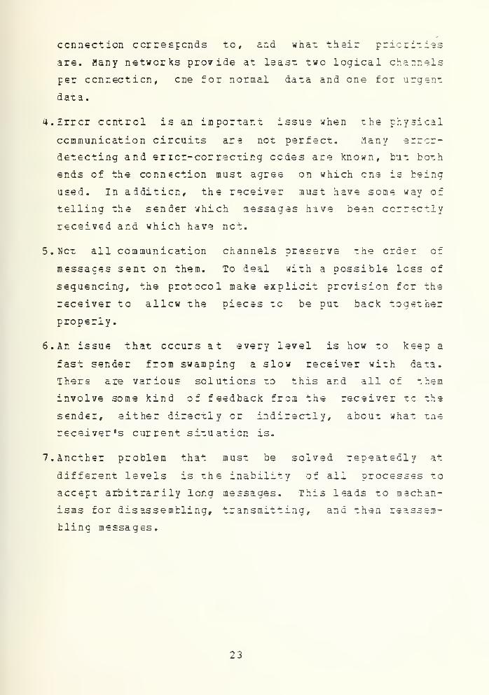
connection corresponds to, and what their priorities
are. Many networks provide at least two logical channels
per connection, cne for normal data and one for urgent
data.
4. Error control is an important issue when the physical
communication circuits are not perfect. Many errcr-
detecting and ericr-cor recting cedes are known, but both
ends of the connection must agree on which cne is being
used. In addition, the receiver must have some way of
telling the sender which messages have been ccrrectly
received and which have net.
5. Net all communication channels preserve the order of
messages sent on them. To deal with a possible loss of
seguencing, the protocol make explicit prevision for the
receiver to allow the pieces to be put back together
properly.
6. An issue that occurs at every level is how to keep a
fast sender from swamping a slow receiver with data.
There are various solutions to this and all of them
involve some kind of feedback from the receiver to the
sender, either directly or indirectly, about what the
receivers current situation is.
7.Ancther problem that must be solved repeatedly at
different levels is the inability of all processes to
accept arbitrarily long messages. This leads to mechan-
isms for disassembling, transmitting, ana then reassem-
bling messages.
23

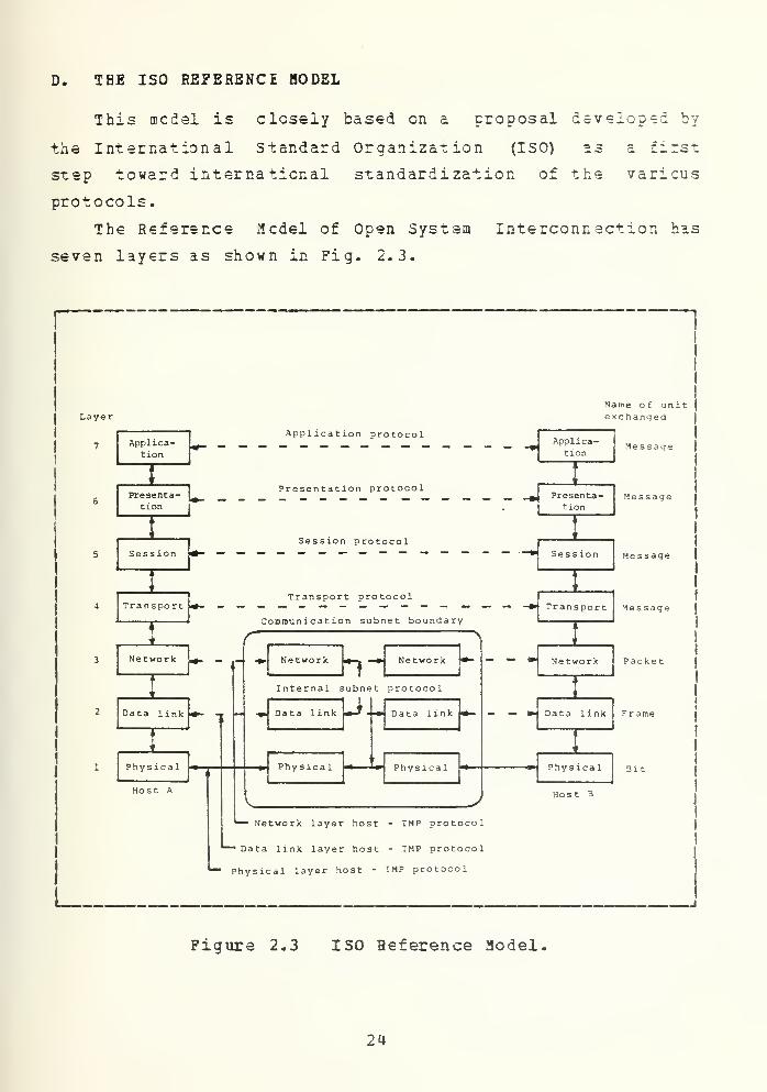
D. THE ISO REFERENCE MODEL
This medal is closely based on a proposal developed by
the International Standard Organization (ISO) as a first
step toward international standardization of the various
protocols.
The Reference Hcdel of Open System Interconnection has
seven layers as shown in Fig. 2.3.
LayerName of unitexchanged
Applica-tion
Application protocolApplica-
tion
Presentation protocolsenta- _________ _______ _#.
22 1
Presenta-t—
r
Presenta-tion
Sess ion hSession protocol
Sess ion
TransportTransport protocol
Communication subnet boundary'ranspor
t
Network
Data link
i,
Physical
Host A
h Network yInternal subnet protocol
Data link
Phys lea 1
Data link
Phys ica
1
J
Ne twork
I
Message
Message
Message
Message
Packet
-M Data link
Phys ical
Host 3
Network layer host - IMP protocol
*" Data link layer host - IMP protocol
Physical layer host - IMP protocol
Figure 2.3 ISO Reference Model.
24


The principles that ISO applied to arrive at the seven
layers are as follows:
1. A layer should be created where a different
level cf abstraction is needed.
2. Each layer should perform a well defined
function.
3. The function of each layer should be chcsen
with an eye toward defining internationally standardized
protocols.
4. The layer boundaries should be chosen to
minimize the imformation flow across the interfaces.
5. The number of layers should be large enough
that distinct functions need not be thrown together in the
same layer cut of necessity, and small enough that the
architecture does not become unwieldy.
The seven layers, from the lowest layer to the highest
layer, are:
1 .Physical laye r - The physical layer provides
mechanical, electrical, functional and procedural
characteristics to establish, maintain, and
release physical connections (e.g., data-circuits)
between lick-entities. The physical layer provides
for the transmission of transparent bit streams
between data link layer protocols across physical
connections which are permanently' or dynamically
established.
2 -Data Link Layer - The purpose of the data link
layer is tc provide the functional and procedural
means to establish, maintain, and release one or
mere data links among network-entities. This layer
25


masks the characteristics of the physical layer
(such as switched, multipoint, broadcast, polling,
contention, etc.) from the network layer.
3 . Network Laye r - The network layer provides func-
tional and procedural means to exchange network-
services-data- units between two transport-entities
over a network-connection. It provides transport-
entities with independence from routing and
switching considerations, including the case where
a tandem subnetwork-connection is used. The
network layer protocol uses underlying data link
ccnnections to make network connections invisible
to the transport layer protocol.
U. Tra nsport Layer - The transport layer exists to
provide a universal transport service in associa-
tion with the underlying services provided by
lower layers. The transport-service provides
transparent transfer of data between session-
entities. The transport-service relieves these
session-entities from any concern with the
detailed way in which reliable and cost-effe ctive
transfer of data is achieved. Three types of
transport services are:
- A connection-oriented service
- A transaction-oriented service
- A broadcast-oriented service
The transport service is required to optimize the
use of the available communications services to
provide the performance required for each connec-
tion between session-entities at a minimum cost.
To achieve optimization, the global demands of all
concurrent transport users and the transport layer
resource limitations are considered.
26


5. Session l aye r - The purpose of the session layer
is to assist in the support of the interactions
between cocrperating presentation-entities. To do
-his, the session layer provides services which
are classified into the following two categories:
a) Session Administration Services
binding two presentation-entities into
a relationship and unbinding them.
b) Session Dialogue Service - control of
data exchange, delimit and synchron-
izing data operations between two
presentation-entities.
6. Presentat ion Layer - The purpose of the presen-
tation layer is to provide the set of services
which may be selected by the application layer to
enable it to interpret the meaning of the data
exchanged. These services are for the management
of the entry, exchange, display and control of
structured data. The presentation-service is loca-
tion independent and is considered to be on tcp of
the session layer which provides the servic° of
linking a pair of presentation-entities. It is
through the use of services provided by the
presentation layer that applications in an open
systems interconnection environment can communi-
cate without unacceptable costs in interface vari-
ability, transformations or application
modification. There are four phases of presenta-
tion layer protocol operation:
a)Session establishment phase in which
the connection is set up.
21


t) Presentation image control phase in
which the presentation options can be
selected by value, by name, by prior
agreement or by negotiation.
c) Data transfer phase which controls the
data structure accesses and perhaps
executes special purpose transforma-
tions such as voice compression or
data encryption.
d) Termination phase
7 . Apoiicat ion Lay er - This is the highest layer in
the reference model of open systems interconnec-
tion architecture. Protocols of this layer
directly serve the end user by providing the
distributed information service appropriate to an
application, to its management and to the system
management. Management of open systems intercon-
nection comprises those functions required to
initiate, maintain, terminate and record data
concerning the establishment of connections for
data transfer among application processes. The
ether layers exist only to support this layer.
Three categories of application layer protocols
are defined:
a) System Management Protocols - respon-
sible for controlling and supervising
open systems (e.g., initiating
dialog) .
b) Application Management Protocols
responsible for controlling and super-
vising application processes (e.g.,
access control) .
28


c) System Protocols - responsible for
executing information processing func-
tions on behalf of an application
process or user (e.g., electronic
mail) .
29

III. ETHERNET LOCAL AREA NETWORK
A. CfERflEii
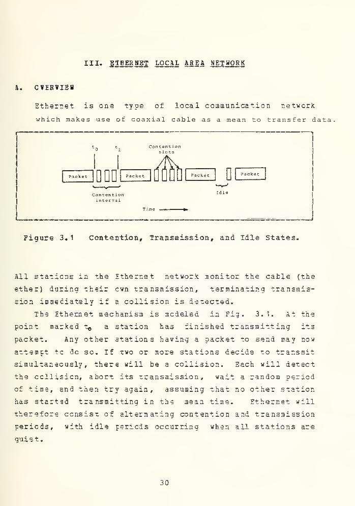
Ethernet is one type of local communication network
which makes use of coaxial cable as a mean to transfer data
Content ioninterval
Idle
Time
Figure 3.1 Contention Transmission, and Idle States.
All stations in the Ethernet network monitor the cable (the
ether) during their own transmission, terminating transmis-
sion immediately if a collision is detected.
The Ethernet mechanism is modeled in Fig. 3.1. At the
point marksd t^ a station has finished transmitting its
packet. Any other stations having a packet to send may now
attempt tc do so. If two or more stations decide to transmit
simultaneously, there will be a collision. Each will detect
the ccllisicn, abort its transmission, wait a random period
of time, and then try again, assuming that no other station
has started transmitting in the mean time. Ethernet will
therefore consist of alternating contention and transmission
periods, with idle periods occurring when all stations are
guiet
.
30


B. CCHCISE ETHEBNET SPECIFICATION
1. Packer Format
I
PREAMBLEI
I
64-BITS
DESTINATIONADDRESS
SOURCEADDRESS
TYPE DATAFRAMECHECK
SEQUENCE
48-BITS 16-BITS 46-1500 BYTES
INTERFRAMESPACING
|
32-BITS 9.6 MICROSEC,
Figure 3.2 Ethernet Packet Format.
A station trust be able to transmit and receive packets on
the ccmmcn coaxial cable with the indicated packet format
and spacing. Each packer should be viewed as a sequence of
8-bit bytes; the least significant bit of each byte
(starting with the preamble) is transmitted firs-.
a) .Maximum Packet S ize : 1526 bytes(8 byte preamble + 14
byte header 1500 data bytes 4 byte CRC)
b) • UiSJLi3J8 P a c ke t Size: 72 bytes (8 byte preamble 14
byte header + 46 data byres 4 byte CRC)
c ) « Preamble; This 64-bit synchronization pattern contains
alternating 1's and 0's, ending with two consecutive
Vs.
d) . Cestin ati cn Addr ess : The 48-bit field specifies the
station (s) to which the packet is being transmitted.
Each station examines this field to determine whether
it should accept the packet. The first bit transmitted
31


indicates the type of address. If it is a 0, the field
contains the unique address of the one destination
station. If it is a 1 , the field specifies a logical
grcup cf recipients; a special case is the broadcast
(all stations) address, which has all Vs.
9 ) • Source Address: This 48-bit field contains the unique
address of the station that is transmitting the packet.
f ) 'll£§. gigld: This 16-bit field is used to identify the
higher level protocol type associated with the packet.
It determines hew data field is interpreted.
g) .Data Field: The field contains an integral number of
bytes ranging from 46 to 1500. (The minimum ensures
that valid packets will be distinguishable from colli-
sion fragments.
)
M -IsSiSfi Check Sequence : This 3 2- bit field contains a
redundancy check (CRC) code, defined by the generating
polynomial:
G (X) = X32 + X 26 *X 23 +X22* X* 6 +X l2+X l l
+ X l0 + X9 + X 7+X s +X*+X 2 +X + 1
The CRC covers the address (destination/source) , type,
and data fields. The first transmitted bit of the desti-
nation field is the high-order term of the message
polynomial to be divided by G(x) producing remainder
R (x) . The high-order term of R (x) is the first trans-
mitted bit of the Packet Check Sequence field. The algo-
rithm uses a linear feedback register which is initially
preset to all 1's. After the last data bit is trans-
mitted, the contents cf this register (the remainder)
are inverted and transmitted as the CRC field. After
receiving a good packet, the receiver's shift register
certains 11000111 00000100 11011101 01111011 (x3i...
,x<>) .
32


i) , Minimum Packet Spa cing: This spacing is 9.6 microse-
cond, The minimum time that mast elapse after one tran-
smission before another transmission may begin.
i) . Hound-Trip Delay: The maximum end-to-end, round-trip
delay fcr a bit is 51. 2 microsecond.
M -Collision Filter ing : Any received bit sequence smaller
than the minimum valid packet (with minimum data field)
is discarded as a collision fragment.
2 . Ccntrol Procedure
The control procedure defines how and when a host
station may trasmit packets into the common cable. The key
purpcse is a fair resolution of occasional contention among
transmitting stations.
a) .Defer: A staticn must not transmit into the coax cable
when the carrier is present or within the minimum
packet spacing time after the carrier has ended.
b) . Transmit: A station may transmit if it is not defer-
ring. It may continue to transmit until either the end
cf the packet is reached or a collision is detected.
c) -Abort: If a collision is detected, transmission of the
packet must terninate, and a jam (4-6 bytes of arbi-
trary data) is transmitted to ensure that all ether
participants in the collision also recognize its occur-
rence.
&)
•
Betransmit : After a station has detected a collision
and aborted, it must wait for a random ret ransmi ssion
&S1&1' defer as usual, and then attempt to retransmit
the packet. The random time interval is computed using
the backoff algorithm (below). After 16 retransmission
attempts, a higher level (e.g. software) decision is
33


lade tc determine whether to continue or abandon the
effort.
e ) •E§^JS2U : Retransmission delays are computed using the
Truncated Binary Exponential Ba cko ff algorithm, with
the aim of fairly resolving contention among up to 1024
stations. The delay (the number of time units) befcre
the nfk attempt is a uniformly distributed random number
from to 2 for 0<n<10 (n - is the original attempt) .
For attempt 11-15, the interval is truncated and
remains at to 1023. The unit of time for the retrans-
mission delay is 512 bit times (51.2 microsecond).
- • Channel Enc od ing
Manchester encoding is used on the coaxial cable. It
has a 50*? duty cycle, and insures a transition in the middle
L— Bit Call -mi
_J—
L
I I—L_U- 100 ns ——•4 L
High (also quiescent state)
Low
0. 75 1. 25
Determination of Carrierat receiver
Logic High : 1 = raA = V
Logic Low : =-82mA = -2.05 V
Cable has volts in quiescent state
Figure 3.3 Data Hate Scheme.
cf every bit cell ("data transition")- The first half of
the bit cell contains the complement of the bit value, and
the second half contains the true value of the bit.
34


H . Cat a Rate
Data rate is 10 Mbit/sec = 100 nsec bit call ±
0.01*.
5
.
Carrier
The presence of data transitions indicates that
carrier is present. If a transition is not seen between
0.75 and 1.25 bit times since the center of the last bit
cell, rhen carrier has been lost, indicating the end of a
packet. For purposes of deferring, carrier means any
activity en the cable, independent of being properly formed.
Specifically, it is any activity on either receive or colli-
sion detect signals in the last 160 nsec.
6 . Coax Cable
a ) •J2L£l£§!£§- 50 chms ± 2 ohms (Mil Std. C17-E) . This
impedance variation includes batch-to-batch variations.
Periodic variations in impedance of upto ± 3 ohms are
permitted along a single piece of cable.
b) *
C
able Loss : The maximum loss from one and of a cable
segment to the ether end is 8.5 db at 10 MHz {equiva-
lent tc °500 meters of low loss cable)
.
c) . Shieldi ng : The physical channel hardware must operate
in ar. ambient field of 2 volts per meter from 10 MHz to
30 MHz and 5 volts per meter from 30 MHz to 1 GHz. The
shield has a transfer impedance of less than 1 millichm
per meter over the frequency range of 0.1 MHz to 20 MHz
(exact value is a function of frequency)
.
d) -Ground Con nection: The coax cable shield shall not be
connected to any building or AC ground along its
length. If for safety reasons a ground connection of
the shield is necessary, it must be in only one place.
35


a) . Physical Dime ns ions : This specifies the dimension of a
cable which can be used in the standard tap. Cther
cables may alsc be used, if they are net to be used
with a tap-type transceiver (such as used with connec-
tcrizsd transceivers, or as a section between sections
tc which standard taps are connected) .
Center Conductor
Core Material:
Core 0. D.
:
Shield:
Jacket:
Jacket C. E.
:
0.0855" diameter solid tinned copper
Foam polyethylene or foam teflon F2F
0.24 2" minimum
0.326" maximum shield O.D.
PVC or teflon FSP
0.405"
TransceiverCable
Coax Cable Segment (1 electrical segment)
Coax Cable Section
Liir^rrTerminator
'-Era
TapTransceiver
Host|
StationI
Fema 1 e-Fema leAdapter (Barrel Cable
Connector
•~1
oII I I g Male CoaxConnector ' |
~* Terminatorj
Female_ Connector i zed|
Transceiver
Male CableConnector
("[Host
JjStation
Figure 3.4 Coax Cable, Connectors, and Transceivers.
7 . Coax Connecters and Terminators
Coax cables must be terminated with male N-series
connectors, and cable sections will be joined with fecraie-
female adapters. Connector shells shall be insulated such
that the coax shield is protected from contact to building
36


grounds. A sleeve cr boot is acceptable. Cable segments
should b€ terminated with a female N-series connector (can
be made up of a barrel connector and a male terminator)
having an impedance cf 50 ohms 1%, and able to dissipate 1
watt. The outside surface of the terminator should also be
insulated.
8 • Tran sceiver
Up to 1 00 transceivers may be placed en a cable
segment nc closer than 2.5 meters. Following this placement
rule reduces to a very low (but not zero) probability the
chance that ob jecticnable standing waves will result. The
details cf transceiver interface and coax cable interface
can be fcund in Interlan's "Concise Ethernet Specification"
[Ref. 3].
C. NI1010 0NIBOS ETHERNET COMMUNICATIONS CONTROLLER
1 . Featur es
a ) » Ethernet Data Link Laver Functions:
1) .Data Encapsulation/decapsulation
2) .Carrier Sense Multiple Access/Collision Detected
(CSMA/CD) transmit and receive data link management
b) -Ethernet P hysical Channel Functions:
1) . 10 Kbits per second data rate
2). Data encoding and decoding
3). Channel access
4) .Transceiver cable interface
c ) •J®S w.£sJS Statistics:
1) .Tallies number of transmissions, receptions, errors,
and collisions
^) • Performance :
37


1) . 1 6 Kbytes FIFC buffer for back-to-back frame recep-
tion
2) . 2 Kbyte FIFO buffer for frame transmission
3) .DMA transfers to/from unibus memory
s ) » Extensive Diagno sti c F eatures:
1). internal and external data loop-back operation
2). Network LED indicators
3).Ecwer-up confidence test
U). Pass/fail LED indicator
5) .Diagnostic software provided
f ) »Cne Kex-Hight B eard :
1).Fit one unibus SPC slot
2 • Description
The NI10 10 Unibus Ethernet Communication Controller
Board is a single Hex-height beard that contains all the
data communications controller logic reguired for inter-
facing DEC»s family of VAX- 11 and Unibus-based PDP-11 mini-
computers to the Ethernet local area network. It performs
the specified data link and physical channel functions,
permitting Unibus-based systems to engage in transmission
and reception of data with other Ethernet stations on the
local area network with the speed of 10 Mbit per second and
with the maximum distance of 2500 meters. As shown in Figure
3.5, the NI1010, when attached to a transceiver unit,
provides a VAX-11 or Unibus-based PDP-11 a complete connec-
tion cntc the Ethernet local area network.
3 . Eth ern et dat a link layer functions
Within the data link layer the NI1010 performs the
specified Ethernet transmitter processes of Transmit Data
Encapsulation and Transmit Link Management, and the Ethernet
receive processes of Beceive Data Decapsulation and Receive
Link Management.
38


ISO gEFERENCE MODELFOR OPEN SYSTEM INTERCONNECTION
ETHERNETCLIENTLAYERS
ETHERNETvl.O
SPECIFI-CATION
APPLICATION LAYER
PRESENTATION LAYER
TERMINATOR
SESSION LAYER
TRANSPORT LAYER
NETWORK LAYER
DATA LINK LAYER
PHYSICAL LAYER
COAX CABLE
r j—u—u
—
u—u—u
—
L
y-
NI 1010UNIBUS ETHERNETCOMMUNICATIONS
CONTROLLER
F=3^^
FLATCABLE
L (i To 50 M
TRANSCEIVERCABLE
aTRA NSCEIVER -J L
UNIT1 w '
Figure 3.5 Ethernet Architecture and Implementation.
a. Transmit data encapsulation
Figure 3.6 shows the Ethernet Frame Format for
packet transmissions over the coaxial cable physical
channel. Fcr receive synchronization purposes, the frame is
preceeded with a 64-bit preamble sequence and terminated
with a minimum interframe spacing period of 9.6
microseconds.
39


The Destination Address field specifies the
station (s) for which the frame is intended. The address
value provided by the user may be either; 1)the physical
address of a particular station on the network; 2) a
mult icast-grcup address associated with one or more
stations; or 3) the broadcast address for simultaneous tran-
r
—
1
y
Preamble
64
Dest .
Addr.
48
SourceAddr .
48
Type
16
DataField
CRC
32
Pr eambl
e
64
Dest .
Addr .
48
Sour eel, , TypeAddr .
r '
48 1 16
Da ta
Field
CRC
32
L CRC c f ields_1. . Minimum
1
1
I
:over
s
thes)
er spacing
Figure 3.6 Ethernet Fraae Foraat.
amission to all statiens on the network. The first bit of
the Destination Address distinguishes a physical address
from a multicast address (0 = physical, 1 = multicast) . For
broadcast transmissions an all one-bit pattern is used.
The Source Address field specifies the physical
address cf the transmitting station. To eliminate the possi-
bility of an addressing ambiguity on a network, associated
with each NI1G10 is a unique 48-bit physical address value
assigned to it at the time cf manufacture. On transmission,
the NI1010 inserts this value into the Source Address field.
The type field is specified by the user for use
by high level network protocols. It specifies to the
receiving station(s) how the content of the Data field is to
be interpreted.
40


The Data field may contain a variable number of
data bytes ranging from a minimum of 46 bytes to a maximum
of 1500 bytes. The NI1010 accepts less than 46 bytes from
the user by automatically , inserting null characters to
complete a 46-byte minimum frame size.
The Frame Check Sequence (PCS) field contains a
32-bit cyclic redundancy check (CRC) value generated by the
NI1010 during transmission.
fc. Transmit link management
The NI10 10 performs all Ethernet Transmit Link
Management functions required to successfully deliver a
frame ontc the network. These functions include:
• Carrier Deference; the NI1010 monitors the physical
channel and defers its transmission should the channel
be busy carrying ether traffic;
• Collision Detection; once the NI1010 has finished defer-
ring to the passing traffic on the network, it proceeds
with its own transmission. In the event that another
station simultaneously began a transmission, a "cclli-
sicn" cccurs. The NI10 10 detects this event and termi-
nates its transmission attempt; and
• Ccliisicn 3ackoff and Retransmission; when a transmis-
sion attempt has been terminated due to a collision the
NI1010 attempts its transmission again after delaying a
short random period of time. The scheduling of the
retransmission is determined by the Ethernet process
called "truncated binary exponential backoff". The
NI1010 reports an error should it be unable to deliver
its frame onto the network after 16 transmission
attempts.
41


c. Receive data decapsulation
When not transmitting a frame the NI10 10 conti-
nuously listens to the traffic being carried on the network.
After synchronizing to the preamble sequence of a frame on
the network, the NI1010 processes the Destination Address
field through its address filter logic to determine whether
cr net the incoming frame is intended for it. The NI1010
controller will only accept a frame from the network with a
Destination Address value that either:
1) matches the physical address of the NI1010 hoard
itself;
2) contains the broadcast address; or
3) matches one of the 63 multicast-group logical
addresses which the user may assign to the board.
The NI10 10 performs high speed multicast-group
address recognition. Whenever a multicast-group logical
address is received en the network, the NI10 10 converts the
frame's 48-bit Destination Address field into a 6-bit table
entry pointer through the application of a many-tc-few
mapping called "hashing". It uses the resulting pointer to
look into a table of valid multicast-group addresses to see
if the received address is one that the station should
accept.
For network management and diagnosis, the NI1010
may be operated in a "promiscuous" receive mode. When in
this node, the NI10 10 disables its address filter logic and
accepts all undamaged frames passing on the network.
The NI10 10 validates the integrity of a received
frame by regenerating the 32-bit CRC value on the received
bit stream and comparing it against the CRC value found in
the frame's Frame Check Sequence field.
f
42


d. Peceive link management
Since collisions are a normal occurrence in the
Ethernet's CSMA/CD link management process, the NI1010
receiver filters out collision fragments from valid frames.
**• Ethernet phys ica l lay,er func t ions
Within the Ethernet Physical Layer the NI1010
performs the electrical and procedural specifications
required fcr interfacing directly to a transceiver unit.
Transmissions and receptions take place at a 10 Mbits per
second data rate under half -duplex operation.
a. During transmission the NI1010*s physical
channel functions include:
1) .Generating the 64-bit preamble sequence for all
receivers on the network to synchronize on;
2) .Parallel to serial conversion of the frame;
3) . Calculating a 32-bit CRC value and inserting it into
the Frame Check Sequence field;
4) . Generating a self -synchronizing serial bit stream
through Manchester encoding of the data; and
5). Providing proper channel access by detecting carrier
frca another station's frame transmission, and sensing
the collision presence signal from the transceiver
unit.
b. The NI10 10's physical channel functions during
reception include:
1) . Manchester decoding the incoming bit stream into a data
stream and a clock stream;
43


2) . Synchronizing to, and removal of, the preamble
sequence; and
3) .Serial to Parallel conversion of the frame.
5 • Performance
The NI1010 has been designed to offer high network
performance while minimizing the service loads placed upon
the host Unibus system.
Serving to buffer the system from tne unpredictable
interarrival times characteristic of network traffic, the
board has a FIFO (first-in, first-out) memory which can
store up to 16 Kbytes of received frames. Because of this
extensive front-end buffering, few time-critical service
requirements are impcsed on the host Unibus system.
Fcr transmission, the NI1010 has a 2 Kbyte Transmit
FIFO which permits the host to perform a one-time transfer
of a frame.
All data block transfers between the NI1010 and
Unibus memory are performed under the control cf an onboard
DMA controller. To maximize system performance during recap-
tion, the controller allows the user to preload up to
sixteen different memory buffer address and byte count
values fcr DMA of received frames.
6 • Extensive Diagnost ic Features
The NI10 10 offers comprehensive network and beard-
level diagnostic tools which greatly simplify the process of
identifying a network communication problem. Mounted on the
edge of the board are four network state LED indicators
which provide a visual indication of whether or net the
user's station is cemmunicating onto the network. For a
comprehensive station diagnosis, the user can exercise the
NI1010's communication facilities in either internal or
44


Interrupt vectoraddress switch
Data
m Databus
1tltHRCV vectorCMD vector
I
kfcAddr
Addressbus
Bu s
arbitrationcontrolunit
Control
VI
Bus register fi le
A CSR |
Addressdecoder
/,
BAR ]BCR
WHHMase addrr I
witches I , J
Data|muxdemux
Da t£
ce 1 ver
s
1
Addrreg
mJJ"lr*CV done^Y 1-RCV IE
|
/ — ? c v vectoi
Bytereq
1
Zero
rRamAddr
andbyte,coun t,
DMA controller
Addresscontro
1
Networkstate
NM 10Ethernetprotocolmodu 1
e
/\J\ /H-CHD donVjjy* •/-V^J-CMD IE
DMA request.r—
•
DMA grant -
+ 5 V
+ 15 V
State machine
Inputtestcond i t ic
r
i
Sequencer-.-
T J
rolLED
driver
LED indicators
-O Carrier-Qcol 1 isionQ Tr ansmit{^Receive
Figure 3-7 NI10 10 Functional Diagram-
external data loopback mode; making it possible to detect
and isolate a fault to the coaxial cable, transceiver unit,
transceiver cable; or the NI1010 board itself.
Cn power-up the NI1010 performs a confidence test of
the cntcard memories, register and data paths. A L2D indi-
cator shows the pass/fail operational state of the board.
7 • Network stat istics
The NI10 10 collects network statistics to permit the
user to characterize network operation- Statistics tallied
include
:
a) .number of frames received
b) .number cf frames received with CRC error
c). number cf frames received with alignment error
45


d). number of frames transmitted
e). number of transnit collisions
For detailed description of NI1010 Ethernet
Communicaticn Controller Board, see NI1Q10A Unibus Ethernet
Communications Controller User Manual [Ref. 4].
46


IV. DETAIIJD DESIGN AND IMFLEHENTATION
A. DESIGN ISSUES CONSIDERATION
After studying the NI10 10 Unibus Ethernet Communications
Contrcller in detail, some of the common problems with the
design of protocol mentioned in Chapter II can be solved as
follows:
I.The nethod needed for a process on one machine to
specify who it wants to talk to is the Destination
Address and the Source Address field in every trans-
mitted frame.
2. There is no need to find a mechanism for terminating the
connection across the network, since the Ethernet will
put itself to the idle state automatically if there is
nc carrier on the coax cable.
3. The rule for data transfer is fixed on the half-duplex
operation, i. e. , the data can travel in either direction,
but not simultaneously.
U.Fcr the errcr control issue, Ethernet frame format
provides a 32-fcit Frame Check Sequence field which
contains Cyclic Fedundancy Check (CRC) value. This
value is generated by the Ethernet board of the sending
station and will be checked by the board of the
receiving station.
5. The problem of how to keep a fast sender from swamping a
slow receiver with data is solved by the 16 Kbyte FIFO
Beceive buffer on all Ethernet boards.
47


6. Ethernet board performs data link layer in transmitting
data encapsulation and receive data decapsulation. The
data field of the frame format can vary from 46 to 1500
bytes. Thus, the design issue of the ability of
processing arbitrarily long messages is solved.
Furthermore, if the data is less than 46 bytes, the
board will automatically insert null characters to
complete a 46-byte minimum frame size.
However, the problem of preserving the order of messages
is net solved by the capability of the Ethernet board. The
design of a higher layer protocol would have to take this
issue into consideration. The forthcoming sections will
explain hew to create a design such that it will overcome
this problem.
The NT 1010 Unibus Ethernet Communications Controller
Board together with the Transceiver represent the first two
layers. Physical Layer and Data Link Layer, of the ISO
Reference Model as shewn in Figure 4.1.
E. HS2030 DEVICE DRIVER
1 . Ove rvi ew
The NS2030 product includes a diagnostic program and
a VAX/VMS device driver source, hereafter referred to as
NIDRIVER, that allows a suitably privileged application
program written in VAX- 11 MACRO assembly language or any
VAX/VMS high level language (such as VAX-11 FORTRAN) to
interface tc INTERLAN's Unibus to Ethernet interface, the
NI10 10. The application program uses standard VAX/VMS
services to interface to the Ethernet. There are nc new
interfaces tc learn. NIDRIVER supports all features of the
NI10 10 controller, including full duplex operation (trans-
mitting with receives outstanding) , non-contiguous buffers
43


r \—u u
—
u—u
—
ltISO REFERENCE MODELFOR OPEN SYSTEM INTERCONNECTION
ETHERNETCLIENTLAYERS
ETHERNETvl.O
SPECIFI-CATION
TERMINATOR
APPLICATION LAYER
PRESENTATION LAYER
SESSION LAYER
TRANSPORT LAYER
NETWORK LAYER
DATA LINK LAYER
PHYSICAL LAYER
y
COAX CABLE
NI 1010UNIBUS ETHERNETCOMMUNICATIONS
CONTROLLER
FLATCAni.E
^ fTo 50 M
TRANSCEIVERCABLE
ATRANSCEIVER
UNIT
Figure 4.1 HI1010 and ISO Reference Model.
for transmission and reception (often called "scatter/
gather" cr "buffer chaining"), and the extensive cnhoard
intelligence and diagnostic functions. The standard QIO
interface allows the network software designer to choose
among several tachnigues for performing I/O: synchronous
I/O using the SQIOW system service, and asynchronous I/O
using the $QIO system service with event flags and/cr AST
routines.
49


With one $QIC request, an application program is
able to instruct the NI1010 to obtain a pr ef crmatted
Ethernet packet out cf system memory and transmit it onto
the Ethernet. Similarly, with one $QIO request, the program
can specify the address and length of a buffer in system
memory into which the controller can place the next received
packet. Single $QIC requests can also be used to perform
ether NI1010 functions such as GO ON-LINE, RUN DIAGNOSTICS,
REPORT STATISTICS, and LOAD GROUP ADDRESS (ES).
The detailed description of NIDRIVER is contained in
the Interlan NS2030 VAX/VMS (TM) Device Driver and
Diagnostics User Manual [Ref. 5].
2 « Program inter faces to NIDRIVER
Detailed descriptions of the following standard
VAX/VMS system services can be found in the VAX/VMS System
Services Reference Manual [Ref. 6] and in the VAX/VMS I/O
User's Guide [Ref. 7]. Some of the very important system
services are also included in Appendix A.
a. Using Sassign (associate channel) with NIDRIVER
Before a program can issue requests to NIDRIVER,
it must assign a channel to the NI1010 controller. The
Assign I/O Channel (SASSIGN) system service is used to
assign a channel to a device. You supply the device name as
part cf the SASSIGN call: SASSIGN returns a channel number.
The NI1010 controller device name supported by NIDRIVER is
cf the form NIxy: Because the NI1010 controller represents a
single "unit" (in the VMS I/O sense) , the first ccntrclier
is called "NIAO:", the second "NIBO:", and so on.
50


b. Using $AIIOC (allocate device) with NIDRIVZP
A process can allocate a device for its exclu-
sive use using the SflLLOC system service. Once the device is
allocated, no other process (except for subprocesses related
to the issuing process) can assign a channel to the device.
Because the NI1010 controllers provide low level
access to the Ethernet. NIDRIVER supports each controller as
a non-sharable device. When a process assigns a channel to
an NI1010 controller, VAX/VMS performs an implicit SALLOC
for the process.
c. Using SGETCHN and $GETDEV (get device
Information)
Two system services can be used to obtain infor-
mation about NIDBIVER: Get Channel Information (SGETCHN) and
Get Device Information (SGETDEV) . SGETCHN is used to obtain
information about a specific device.
When used to obtain information about an NI1010
controller, these system services return identical primary
and secondary device characteristics.
d. Using $QIO and $QIOW (request I/O function)
Because NIDRIVER supports the standard VAX/VMS
QIO interface, all controller requests follow the general
CIO format:
$QIC_S [efn ],chan,func,[ iosb ],[astadr ],[ astprm ],
Cp1].Cp2]rCp33,Cpa],[p5],C?6]
The first six arguments are device/function
independent and can be used in any controller I/O request.
For example, you can specify an AST routine address (the
"astadr" argument of the QIO request) if you need to execute
special cede at I/O completion.
51


Device/function dependent arguments ?1 and P2
must be supplied for all controller operation that use the
DMA channel for transferring data to or from VAX memory. P1
is the (virtual) address of a WORD-ALIGNED buffer. P2 is the
size of the buffer in bytes and must be even and less than
1536 (decimal). Parameter P3 through P6 are ignored in
NI1010 operations.
) • IZP. funct ions. To fully understand the
I/O functions supported by NIDRIVER, one should kncvi how
VAX/VMS I/O functions are encoded into 16-bit values (the
function argument of the QIO request) . I/O function values
have the following fcrmat:
15 6 5
+ *
function modifiers code
+ + +
The low-order 6 bits of the function value
are a code that specifies the particular operation to be
performed. The high-crder 10 bits of the function value are
function modifiers and are normally used to alter the parti-
cular operation specified by the cods. Symbolic names for
function codes and modifiers are defined by the SIODEF
macrc, as described in the VAX/VMS System Services Reference
Manual [Ref. 6]. A modified function can be invoked by
"OR"ing a function code and function modifier. For example:
IO$_SETMODE!IO$_5HUTDOWN
in MACRC assembly language, or
I0$_SETMODE .OR. IO$_SHUTDO WN
in FORTRAN.
52


The following describes each I/O function
supported by NIDRIVER.
I2i.SE12ig DE! 10$ STARTOP
Issuing a QIO with a "func" argument of
IO$_SETM0EE!IO$_START0P causes NIDRIV2R to begin controller
operation. NIDRIVER will allocate necessary VAX/VMS
resources and pass a GO ON-LINE command to the NI1010 cont-
roller. The controller and driver will now be in a state to
process commands and receive packets.
Cue can modify NIDRIVER 's resource allocation strategy at
run-time. To change strategy, one's program must supply (in
the ICS_SETMODE! IO$_START0P QIO) the address of a quadwcrd
characteristics buffer in parameter P1 and the size in tytes
(always 16) of the characteristics buffer in ?2. The first
longwcrd (32-bit word) of the characteristics buffer is
interpreted by NIDRIVER as fellows:
<3:0> the maximum number of receive buffers that
NIDRIVER will pass to the controller with SUPPLY
RECEIVE BUFFER commands (maximum of 16). NIDRIVER
will allocate 5 Unibus Adapter map registers for
each as a result of this call. If this field is
zero, NIDRIVER will use a default value of 4 and
allocate 20 map registers for receive operations.
(Five additional map registers are ALWAYS allo-
cated for command DMA.)
<3 1:4> RESERVED (must be zero)
The second longwcrd of the characteristics buffer is inter-
preted by NIDRIVER as follows:
<0:C> = (Default) Allocate a Buffered Data Path
only when needed to process command operations
53


that perform DMA. Deallocate the Buffered Data
Path immediately after the command is finished.
<0:C> = 1 Permanently allocate a Buffered Data Path
tc be used for command operations That perform
DMA.
<31:1> RESERVED (must te zero)
I2i_SElM0 D E ! 10$ SHUTDOWN
Issuing IO$_SETMODE ! IO$_SH UTDOWN causes HIDRIVER to shut
down network operations. NIDRIVER passes a RESET command to
the controller. All outstanding receive (I0$_READL3LK)
requests will finish with a status of SS$_ASORT. Any allo-
cated Buffered Data Path will be deallocated. Any supplied
characteristics buffer is ignored for This call.
10$ WRITEL3LK
Issuing IO$_WRITELBIK causes the packet defined by QIO
parameters E1 and P2 to be transmitted onto the Ethernet. P1
is the address of a WORD ALIGNED preformatted packet in
memory. P2 is the length in bytes of the preformatted
packet. P2 must be greater than and less than 1536
(decimal) and even. The packeT must follow the format
described in Figure 4.2. The QIO request will remain
outstanding until the packet is successfully transmitted
onto the Ethernet (or an error occurs) . The IO$_WRITEPBLK
function performs the same operation as the IO$__WRITELELK
function.
10$ READLELK
Issuing IC$_READLBLK causes the buffer defined by QIO param-
eters P1 and ?2 (address and size in bytes, respectively) to
be used tc hold the next received packet (or packet fragmenT
if buffer-chaining takes place). The buffer pointed to by P1
54

f
iS 8 7
1
J
BAR +0
+ 2
+ 4
+ 6
+ 8
BAR+BCR
DESTINATION ADDR.(B) DESTINATION ADDR. (A)
NI 1010 physicaladdr. is inserted
^- into the SourceAddr . Field on
,
transmission
32-bit CRCgenerated by
DESTINATION ADDR(D) DESTINATION ADDR. (C)
DESTINATION ADDR. (F) DESTINATION ADDR.(E)
TYPE (1 ) TYPE (0)
DATA ( 1 )DATA (0)
•
•
•
m DATA J
•
•
•
don ' t care DATA (last byte)
the NI1010 ontransmission
!
Figure 4.2 Transmit Packet Format,
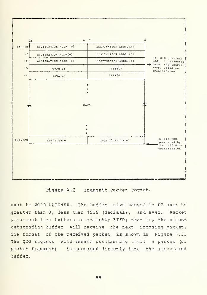
must be WCRD ALIGNED. The buffer size passed in P2 must be
greater than r less than 1536 (decimal), and even. Packet
placement into buffers is strictly FIFO; that is, the oldest
cutstanding buffer will receive the next incoming packet.
The format of the received packet is shown in Figure 4.3.
The QIO request will remain outstanding until a packet (or
packet fragment) is accessed directly into the associated
buffer.
55


15 8 7
BAR + FRAME STATUS
+ 2 FRAME LENGTH
+ 4 DESTINATION ADDR. (E) DESTINATION ADDR. (A)
+ 6 DESTINATION ADDR. (D) DESTINATION ADDR. (C)
+ 8 DESTINATION ADDR.(F) DESTINATION ADDR.(B)
+ 10 SOURCE ADDR .(B) SOURCE ADDR. (A)
+ 12 SOURCE ADDR. (D) SOURCE ADDR .(C)
+ 14 SOURCE ADDR .(F) SOURCE ADDR. (E)
+ 16 TYPE (1
)
TYPE(O)
+ 13 DATA (1) DATA (0)
m
•
•
# DATA X9
•
CRC(24 : 31) DATA (last byte)
CRC (8:15) CRC (16:23)
Undefined CRC (0:7)
BAR+BCR1
i a
FRAME LENGTH(# bytes)
Figure 4.3 Receive Packet Format.
C cntrqller Specific Functions
Eecause no existing VAX/VMS function cedes correspond to
NI10 10 specific operations such as LOAD MULTICAST or SET
FROMISCUCES MODE, NIEEIVER supports driver-specific function
codes. These codes are constructed by passing the
contrcller-specific command in the "function modifier" field
of the I/C function value. The function value "code" field
will be IC$_READL3LK, I0$_W RITELBLK, or IO$_SEEK, depending
56


or whether the cont rcller-specif ic command performs iirsct
memory access or not. For example, the following function
value specifies LOAD MULTICAST:
X20 ! < 052 3 6> = XAAO
Ss a programming convenience, INTERLAN provides symbolic
names which can be used in the function argument of QIO
service calls. File NIDEF.MAR can be used with y.ACRO
programs and file NIDEF. FOR can be used with FORTRAN
programs.
One can use these definitions in a FORTRAN program by
including the line:
INCLUDE »_DRA0:[NPSSYS. INTERLAN ]NIDEF. FOR
•
in the FCETRM source code.
(2) • IZ5 Comp l etion . One should always supply
the address of a guadword I/O status Block (IOS3) IN THE
"iosb" argument of the QIO request. On I/O completion, the
IOSB will contain net only VAX/VMS status, but also cont-
roller specific status as well.
VAX/VMS status is returned in bits <15:0> of the first ICSB
longwcrd. Bits <31:16> of the first IOSB longword dc not
contain any meaningful information. If the returned VAX/VMS
status is SS$_NORMAL, Normal Successful Completion, bits
<3:0> of the second IOSB lengword will contain the Command
Status Code from the controller. Refer to the NI1010 Unibus
Ethernet Communications Controller User Manual [ Ref . 4] for
a ccnplete description of the controller status cedes.
Appendix F describes which Command Status Codes can be
expected for each QIO request. Bits <31:U> of the second
IOSB longwcrd do not contain meaningful information.
57


C. DESIGNING PHOCEDDEE
Since NS2030 Device Driver is intended to be used in
VAX/VMS irini-computer, the design is based on Digital
Equipment Corporation's Network (DECNET) rather than the ISO
Reference Model menxioned in Chapter II. However, the
Layer ISO DECNET
7 App lication
Appli cation6 Present at ion
5 Session ( None
)
4 TransportNetworkServices
3 Ne twork Transport
2 Data link Data linkControl
1 Physi cal Phy s i cal
Figure 4.4 Happing between ISO Hodel and DECNET.
layering ccncept is still used in DECNET. The approximate
mapping between ISO Reference Model and DECNET is shown in
Figure. 4.4.
DECNET has only five layers. The physical layer, data
link layer, transpcrt layer, and network services layer
correspcnd almost exactly to the lowest four ISO layers.
However, the agreement breaks down at layer 5, since DECNET
58


has nc session layer, and the remaining layer, the applica-
tion layer, is a mixture of the ISO presentation and appli-
cation layers.
Apparently, the NS203 has covered both netwcrk and
transpcrt layers, thus, the only layer left to be developed
is the application layer.
1 • Ste^s in developing the a ppl ication layer
With the suggestion from the NS2030 VAX/VMS Device
Driver and Diagnostic User Manual [Ref. 5], VAX-FORTRAN
programming language is chosen to be used in developing the
applicaticn layer. The other reason to use FORTRAN is
because of the provided function argument of QIO service
call in NIDEF. FOR file in the Driver Routine. This makes it
easier for the programmer to issue commands to the NT1010
Unibus Ethernet Communications Controller Board. Steps in
developing applicaticn layers are as follows:
1) All available system service routines in VAX/VMS
involving I/O operation are studied. Some of the very impor-
tant routines which are used in developing the program are
included in Appendix A.
2) The first experiment is to check whether the
program can really instruct the NI1010 Board what to do.
This is done by writing a program that will send out a
message to the NI1010 Board and direct the board to send the
message tack to itself,i.e., send the message from memory to
the transmit buffer and send that same message back tc the
receive buffer of NI1010 Board. In order to do this, the
NI10 10 Ecard must be put in the INTERNAL LOOP BACK MODE. The
detail of command descriptions available to be used with
NI1010 Eoard can be found in NI1010A Unibus Ethernet
Communicaticns Ccntrcller User Manual [2ef. 4]. The prcgram
that is developed for this experiment is included in
Appendix E.
59


3) The seccnd experiment is to do the same thing
except that this time the message will be sent out tc the
transceiver and ontc the ccax cable, but the Destination
Address field contains the address of the board itself
(02-07-01-OC-07-7F) , thus this message will come back tc the
receive buffer again. This is called "EXTERNAL LOOP BACK
MODE".
U) After the first two experiments are completed
successfully, the Destination Address field is changed to
thai, cf the NS30 10 Beard implemented in the MDS system. We
have two NS3010 Eoards, one with address 02-07-0 1 -00-04-0A
and the ether with address 02-07-01-00-03-EA.
5) The next step is to transfer a file. The same
type of experiment which has been done in sending and
receiving the message is used. The DOWNLOAD and UPLOAD
procedure in the VAX/VMS are studied. All the FORTRAN
statements used in file operation can be found in VAX-11
FORTRAN User's Guide [Ref. 8].
2- Met hod tc Ove rcome Frame Sequ encing
It has been mentioned earlier that the NI1010 Eoard
does not have a capability to preserve the order of
messages. Therefore the design of the application layer
protocol should take this matter into consideration.
The solution is that the convention of communicating
between any two computer systems should be made such that
both stations will be able to know each other's status. The
convention cf communicating has been established as follows:
a) .The receiving station will send an acknowledge message
every time a frame is received successfully. If an
error should occur, no acknowledge message will be
sent.
60


b) .The sending station should wait for the acknowledge
message from the receiving station for a sufficient
amcut of time (protocol in VAX/VMS is set up for 5
seconds), if there is no acknowledge message within
this period of time it will retransmit the same frame
again and wait for the acknowledge message. The same
frame is transmitted for the total of 3 times ( 1 tran-
smission and 2 retransmissions) before the transmit
process will be aborted.
c).The convention used to differentiate whether the frame
is carrying a message or a file is established by the
use of the available Type field (2 bytes) of each
frame. It has been set up as shown in Table I.
' -- - ' -
TABLE I
Type Field Protocol: (All in Hexadecimal)
EYTEJ BYTE2 FUNCTION
00 00 console message
00 FF acknowledge message
OF 00 file transfer-first frame
OF 01 file transfer-intermed frame
OF OF file transfer-1 record file
OF FF file transfer-last frame
61


D- IHPLEHENTATION
The final software protocol (application layer protocol)
whose source code is shown in Appendix C is now available in
VAX/VMS for public use. This program is in the file
ETHERNET .FOB. A user who wants to transfer files or messages
between VAX/VMS and WDS systems can do so by following the
instructions given in VAX/VMS-MDS Ethernet Local
Communication Network User Manual included in Appendix C.
62

• COHCLOSION
The principal goals of this thesis were met. The devel-
oped software protocol was tested with the actual transfer
of messages and files between VAX-1 1/780 under VMS operating
system and MDS System under CP/M-80 operating sysxem. A
file as large as 43 Kbytes was transferred roughly in less
than 42 seconds.
At present, -che program is available in VAX/VMS public
user account under user name "INTERLAN" with password "VMS".
The VAX/VMS-MDS Ethernet Local Communication Network User
Manual is also available in the file "VMSMDS.DAT". The
content in this file is exactly the same as the content in
Appendix E in this thesis. Users who want to do the message
or file transfer can get the hard copy of this file by
simply legging into the VAX/VMS under user name and passwerd
mentioned above and printing the file. Then the steps in the
manual must be followed.
The files in public user account are:
ETHEF1. FOR (source code)
ETHEE 1. EXE (executable code)
This is a program to transfer a message in the INTERNAL
LOCFEACK mode.
SJNDKSG.FOR
SENDWSG.EXE
This is a program to send a message, typed in from the
terminal, from the VAX/VMS to the MDS System. It
retransmits the same message 3 rimes with the interval
of 5 seconds before the transmit process is aborted if
there is no acknowledge signal from the receiving
station.
63


GE1MSG.F0R
GETMSG.EXE
This program waits for the message intended for the
VAX/VMS. It sends back the acknowledge signal tc the
sending station every time it receives a frame success-
fully. The received message is displayed on the screen.
DOWNLOAD.FOR
DCWNICAD.EXE
This prcgram is used tc transfer a specified file from
VAX/VMS to MDS System. It will wait fcr an acknowledge
signal from the receiving station after every frame has
been transmitted. The same frame will be transmitted 3
times with the interval of 5 seconds before the
transmit process is aborted, if there is no acknowledge
signal from the receiving station. The file is trans-
ferred by a record of 128 bytes so it would match the
characteristics cf CP/M records.
U E L A C . F OR
DEL CAD . J. XE
It is a program used to receive the incoming file from
the MDS System. It sends an acknowledge signal tc the
sending station for every successfully received frame.
This prcgram puts VAX/VMS into a ready-to-receive-f ile
mode until control- Y key is pressed.
ETHERNET. FOR
ETHESjjET.EXE
This program is a combination of all the prcgrams
mentioned above. When executed, VAX/VMS will te ready
to receive any message in the network which is intended
for the VAX/VMS. The message will be interpreted
64

whether it is a ordinary message, a request transfer-
ring of file, or a request receiving of file.
1).If the message is an ordinary message, the
program prints that message on the screen,
sends an acknowledge signal to the sending
station, and is ready to receive another
message
.
2) .If the itessage is a request for transferring a
file, the program sends back an acknowledge
signal and transfers a specified file to the
sending station until the whole file has been
transferred successfully. The request for
transferring a file message should include the
filename and filetype, FN. FT, of the file which
the requesting station wants to receive. If the
public user account does not have the specified
file, and error message will be sent to the
requesting station to notify the user.
3) .If the received message is a request for
receiving a file, the program will send an
acknowledge message together with instructions
to the user of the requesting station to open a
new file under the specified FN. FT, receive the
incoming file until its all done, then send a
message to the sending station that the whole
file has been received successfully and then
put VAX/VMS back to r eady-to-receive-message
mode.
All of these files can be copied by any users by typing
the following commands:
$Ccpy
$From: _DRA1 :[ INTERLAN ]FN. FT
65


$Tc: NFN.NFT
where FN. FT is the filename. filet ype of the file tc be
copied from, and NFN.NFT is the f ilename. f ilety pe of the
file to be copied to. The NFN.NFT will appear in the user's
directory after the above sequence of commands have been
executed. It is necessary that the file type of the new file
should be the same as the old file.
Future research with VAX/VMS Ethernet Software Prctocol
should concentrate on trying to make the MDS System terminal
act like a virtual terminal of VAX/VdS. There are system
service routines available in VAX/VMS which support this
capability. Anyone who is interested to do a further
research in this field can get all the information about
these routines from Mr. Albert Wong, VAX professional staff,
in Rm. SP505. The modifications can be made without any
changes in the present programs since this program is
designed with a layering concepts of the network protocol.
Another direction of research is to expand the network
so that VAX/VMS can also communicate with other systems
under different operating systems such as ISIS II or
MCORTEX.
66


APPENDIX A
¥AX/VMS SYSTEM SEBVICE ROUTINES
The followings are the VAX/VMS System Service Routines
which are used in developing the application layer protocol
for The Ethernet Local Area Network.
JASSIGN
SASSIGN - ASSIGN I/O CHANNEL
Ihe Assign I/O Channel system service (1) provides a process
with an I/O channel so that input/output operations can be
performed cr. a device, or (2) establishes a logical link
with a remote node on a network.
High-level Language Fcrmat
SYSlASSIGN (devnam r chan,[ acmode ],[ mbxnam ])
devnam
Address of character string descriptor pointer to the
device name string. The string may be either a physical
device name or a logical name. If the device name
contains a colon, the colon and the characters that
fellow it are ignored. If the first character in the
string is a underscore character (_) , the name is
considered a physical device name. Otherwise, the name
is considered a logical name and logical name transla-
tion is performed until either a physical device name
is found or the system default number of translations
has teen performed.
If the device name contains a double colon (::) , the
system assigns a channel to the first available network
67


chan
device (NET:) and performs an access function en the
network.
Address of a wcrd tc receive the assigned channel
number.
acmode
Access mode to te associated with the channel. The most
privileged access mode used is the access mode of the
caller. I/O operations on the channel can only be
performed from equal and more privileged access modes.
robxnan
Address of a character string descriptor pointing to
the logical name string for the mailbox to be associ-
ated with the device, if any. The mailbox receives
status information from the device driver.
An address of implies no mailbox; this is the default
value.
Notes
1) For details on how to use 3ASSIGN in conjunction with
network operations, see the DECnet-V AX User.'.s Guide
[Ref. 9].
2) Only the owner of a device can associate a mailbox
with the device (the owner is the process that has allocated
the device, either implicitly or explicitly) , and only one
mailbox can be associated with a device at a time. If a
mailbox is associated with a device, the device driver can
send messages containing status information to the mailbox,
as in the following cases:
63


a) .If the device is a terminal, a message indicates
dial-up, hang-up, or the reception of unsolicited
i r. pu t
.
b) .If the target is or. a network, the massage may
indicate that the network is connected cr initi-
ated, cr whether the line is down.
For details on the message format and the information
returned, see the VAU/VMS | /p Useris Guide [Ref. 7],
3) Channels remain assigned until they are explicitly
deassigned with the Deassign I/O Channel (SDASSGN) system
service, or, if they are user-mode channels, until the image
that assigned the channel exits.
4) The SASSIGN service establishes a path to device, but
does not check whether the caller can actually perform
input/output operations to the device. Privilege and protec-
tion restrictions may be applied by the device drivers. For
details en hew the system controls access to devices, see
the VJXZXMS I/O OserJ.s Gu^ld [Bsf. 7].
69


SQIOW - QUEUE I/O REQUEST AND WAIT FOR EVENT FLAG
The Queue I/O Request»and Wait for Event Flag system service
combines the $QIO and $WAITFR (Wait for Single Event Flag)
system services. It can be used when program must wait for
I/O completion.
High-level Language Format
SYSIQICW ([ ef
n
],chan,f unc,[ iosb ],[ astadr ],[ astprm ],
[FlMF2],[p3J,[p4],[p5],[ P 6])
ef n
chan
func
icsb
Number of the event flag that is to be set at request
completion. If net specified, in defaults to 0.
Number of the I/O channel assigned to the devics to
which the request is directed.
Function code and modifier bits that, specify the opera-
tion to be performed. The code is expressed symboli-
cally.
Address of quadwerd I/O status block that is to receive
final completion status.
astadr
Address of the entry mask of an AST service routine to
be executed when the I/O completes. If specified, the
AST routine executes at the access mode from which the
$QIO service was requested.
70


astpr
m
AST parameter to be passed to the AST completion
routine.
p1 to p6
Optional device- and function-specific I/O request
parameters.
The first parameter may be specified as p1 or p1v,
depending en whether the function code requires an
address or a value, respectively. If the keyword is not
used, pi is the default; that is, the argument is
considered an address.
P2 through Pn are always interpreted as values.
Notes
1) The specified event flag is set if the service termi-
nates without queuing an I/O request.
2) The I/O status block has the following format:
31 16 15
BYTE COUNT STATUS
DEVICE- AND FUNCTION-DEPENDENT INFORMATION
a) .status - completion status of the I/O request.
fc).byte count - Number of byte actually transferred.
Note that for some devices this contains only the
lew-crder word of the count.
c). device- and function-dependent information - Varies
according to device and operation being performed.
71


The information returned for each device and func-
tion cede is documented in the VAX/VMS I/O User's
Guide [ Ref . 7].
3) Many services return character string data and write
the length of the data returned in a word provided by the
caller. Function cedes for the $QIOW system service (and
the LENGTH argument cf the SOUTPUT system service) require
length specifications in longwords (32-bit word)
.
If
lengths returned by ether services are to be used as input
parameters for SQIOW requests, a longword should be reserved
to ensure that no error occurs when $QIOW reads the length.
4) For information on performing input and output opera-
tions en a network, see the DECnet-VAX User's Guide
[Ref. 9].
72


JEINTIME
SBINTIUE _ CONVERT ASCII STRING TO BINARY TIME
The Convert ASSCII String to Binary Time system service
converts an ASCII string to an absolute or delta time value
in the system 64-bit time format suitable for input to the
Set Timer ($SETIMR) or Schedule Wakeup ($SCHDWK) system
services.
High-level Language Format
SYSSEINTIM (timfcuf ,timadr)
timbuf
Address of a character string descriptor pointing to
the buffer containing the absolute or delta time to be
converted. The required formats of the ASCII strings
are described in the Notes, below.
timadr
Address of a quadword that is to receive the converted
time in 64-bit fcrmat.
Notes
1) The $BINTIM service executes at the access mode of
the caller and dees net check whether address arguments are
accessible before it executes. Therefore, an access viola-
tion causes an exception condition if the input buffer or
buffer descriptor cannot be read or the output buffer cannot
be written.
2) This service does not check, the length of the argu-
ment list, and therefore cannot return the SS$_INSFARG
(insufficient arguments) error status cede. If the service
does net receive enough arguments (for example, if one omits
73


required ccmmas in the call) , one might not get the desired
result.
3) The reguired ASCII input strings have the format:
Absolute Time: dd-nimm-yyyy hh:mm:ss.cc
Delta Time: ddd hh:mm:ss.cc
lisU le ngt h (bytes) Co ntents Range of values
dd 2 day cf month 1-311 hyphen Required syntax
mmm 3 month JAft, FEB, aAE, APR,MAY, JUN, JUL, AUG,SEP, OCT, NOV, DEC
1 hyphen Reguired syntaxyyyy 4 year 1858 - 9999clank n blank Required syntaxhh 2 hour 00 - 23: 1 colon Reguired syntaxmm 2 minute 00 - 59: 1 colon Reguired syntaxss 2 second 00 - 59• 1 period Required syntaxcc 2 hundredths of 00 - 99
se conddddd 4 number of days 000 - 9999
(in 24 -hour units)
Note that month abbreviations must be upper case. In
contrast with previous versions of VAX/VMS, the hundredths
of second field now represents a true fraction. For example,
the string .1 represents ten hundredths of a second (one
tenth of a second); the string .01 represents one hundredth
of a second. Note also that a third digit can be added to
the hundredths of second field; this thousandths of second
digit is used to icund the hundredths of second value.
Digits beyond the thousandths of second digits are ignored.
4) The following syntax rules apply to specifying the
ASCII input string:
a) . Any of the date and time fields can be omitted.
Fcr absolute time values, the SBINTIM service
supplies the current system date and time fcr nonspe-
cified fields. Trailing fields can be truncated. If
74


leading fields are omitted, the punctuation (hyphens,
blanks, colons, periods) must be specified. For
example, the following string results in an absolute
time of 12:00 en the current day.
12:00:00.00
For delta time values, the S3INTIM service defaults
nenspecified hcurs, minutes, and seconds fields to 0.
Trailing fields can be truncated. If leading fields
are emitted from the time value, the punctuation
(blanks, colons, periods) lust be specified. If the
number of days in the delta time is 0, a must be
specified. Fcr example, the following string results
in a delta time of 10 seconds.
: :10
Note the space between the in the day field and the
twe colons.
b) . Fcr both absolute and delta time values, there can
be any number of leading blanks, and any number of
blanks between fields normally delimited by blanks.
However, there can be no embedded blanks within
either the date or time fields.
The following examples illustrate legal input strings to the
SBINTIM system service, and the time represented by the
output from the $BINTIM system service (translated through
the Convert Binary Time to ASCII String (SASCTIH) system
service). Assume that the current date is 14-JUN-1983
04: 15:28.00.
l£22l ££ SBINIIM
-- :50
— 1984 0: 0:0.
9-NOV-1982 12:32: 1. 1 161
SASCTIM output string
14-JUN-1983 04:50:28.00
14-JUN-1984 00:00:00.00
9-NOV-1982 12:32:01.12
75


22-AEB-1983 16:35:0-0
:: ,1
::.06
5 3: 18: 32.068
20 12:
5
22-APR-1983 16:35:00.00
00 :00:00. 10
00:00:00.06
5 03:18:32.07
20 12:00:00.00
05:00:00.00
76


JSETIKB
SSETTME - SET TIMER
The Set liner system service allows a process to schedule
the setting of an event flag and/or the queuing of an AST at
some future time. The time of the event can be specified as
a absolute time or as a delta time.
When the service is invoked, the event flag is cleared
(event flag 0, if none is specified).
High-level Language Format.
SYSSSETIMR <[efn ] rdaytim ,[astadr] ,[ reqidt ])
efn
Event flag number of the event flag to set when the
time interval expires. If not specified, it defaults to
0.
dayt in
Address of the quadword expiration time. A positive
time value indicates an absolute time at which the
timer is to expire. A negative time value indicates an
offset (delta time) from the current time.
astadr
Address of the entry mask of a AST service routine to
te called when the time interval expires. If not speci-
fied, it defaults to 0, indicating no AST is to be
queued.
reqidt
Numter indicating a request identification. If not
specified, it defaults to 0. A unique request
77

identification can be specified in each set ••imer
requests, or the same identification can be given to
related timer requests. The identification car. be used
later to cancel the timer request(s). If an AST service
routine is specified, the identification is passed as
the AST parameter.
Notes
1) The access mcde of the caller is the access mcde of
the request and cf the AST.
2) If a specified absolute time value has already
passed, the timer expires at the next clock cycle (that is,
within 10 milliseconds).
3) The Convert ASCII String to Binary Time (SEINTIM)
system service converts a specified ASCII string to the
quadwcrd time format required as input to the SSETins
service.


SWAITBR
$WAITFR - WAIT FOR SINGLE EVENT FLAG
The Wait for Single Event Flag system service tests a
specific event flag and returns immediately if the flag is
set. Otherwise, the process is placed in a wait state until
the event flag is set.
High-level Language Format
SYSJWAITFR (efn)
efn
Number of the event flag for which to wait.
Notes
The wait state caused by this service can be interrupted
by an asynchronous system trap (AST) if (1) the access mode
at which the AST executes is more privileged than or equal
in privilege to the access mode from which the wait was
issued and (2) the process is enabled for ASTs at that
access mode.
When the AST service routine completes execution, the system
repeats the SWAITFR request. If the event flag has been set,
the process resumes execution.
79

JCANTIM
JCANTIM - CANCEL TIHEB
The Cancel Timer Request system service(cancels all or a
selected subset cf the Sen Timer requests previously issued
by the current image executing in a process. Cancellation is
based en the request identification specified in the Set
Timer (3SETIMR) system service. If more than one timer
request was given to the same request identification, they
are all canceled.
High-level Language Format
SYSSCANTIM ([regidt] ,[acmode])
reqidt
Request identification of the timer request (s) to be
canceled. A value of (the default) indicates that all
timer requests are to be canceled.
acmode
Access mode of the request(s) to be canceled. The mest
privileged access mode used is the access mode of the
caller. Only Those timer requests issued from an
access mode equal to or less privileged than the resul-
tant access mode are canceled.
Notes
Outstanding timer requests are automatically canceled at
image exit.
80


APPENDIX B
SOUBCE CODE FOB EXPERIMENTS
All the source cede in this appendix was developed from
the step-by-step design of the Etherna- Software Protocol.
Each cf the programs includes a brief explanation of the
function when it is executed.
81


PROGRAM ETHEPl
TRANSFER MESS AGE /INTERNAL L00P8ACK.
c ha r ac t e r *26intsqer*?i n t eger
*
U
inc'ujeincludebyte
text /'This ti e s S a a e will op senti oso ( 2 )
nichan, svslaiowi s y s $ a s s i
' *- d r a : Inossys. interlanl "i' (*iodef )
'
Toacket ( 1 36) , Poac ket ( 1 H b )
nofor
Assign destination address:Toacket (l)='02'xToacket (2):'07'xToacket (3)=' 01
•
x
ToacketCajr'OO'xToacket CS) = '07'xToacket (6)='7F'x
Tyoe assiaoTient: 000 = -nsOf etc.Toacket (7)=' 00'
x
Toacket(8)='00'x
Put data into transmit oacket:
do i = 1 ,2bToacket ()) = icharOext(i :i ))1 = 1*1
end dodo 1=35,136
Toacket ( I ) = ' 00* x
end do
Assign a channel to "JIA0:istat=sys$assian( ' NT A0
' , n i chan, ,
)
if(.not.istat) call 1 i b Ss t oo ( '<va 1 C i s t a t ) )
t yoe * f A i s t a t = i s t a t
or. io$m*-startuD)r
Start uo and ao on line:i s t a t - sys?qiow(,Ual ( n i c h a n ) ,
1 %val(io?«-setTode2 . iOS&MMMFf)if(.not.istat) c?H libf>stoo(%val(istat))i f
C
iosb( 1 ) ,ne. 1 ) call 1 i b$s too (%va1 ( i osb ( 1 ) )
)
tyoe *,' S istat=',istat,' S iosbfl)=',ioso(l)
Internal loooback:i stat=sys?aiow( > % v a 1 C n
i
chan) ,
1 %va 1 ( i o«-«-s i 1 t\ ) ,
2 i osb
/
t t § * i , t )
iff.not.istat-) call Hh5stoo(%va1(istaO)i f ( i osb ( 1 ) .ne . 1 ) call H b$st oo (%va 1 ( i osb ( 1 ) )
)
tyoe *,' I i st at= • , i st at , ' I i osb ( 1 ) = '
, i osb ( 1
)
p pot i scuous :
istat=sys5qiow(/%val (nichan) ,
1 %val(io«-<-SDf*m),? i OSb i t r r t f t i )
if(.not.istaf) call lib?stoo(';val(istat))if(iosn(l).ne.l) call 1 i
b
JstoD ( %val ( i oso ( 1) )
)
82


deceive on error:istat=sys?aio<*(/'<val (nichan) ,
1 %val(io«-«-sroem),2 i osb t t t $ i * r r)i f ( . not. i stat) call 1 ibfstoofXval (istat))if (iosb(l).ne.l) call ! i b$stoo( %va 1 ( i osb ( 1 )
)
)
T raosT i t oackef :
istat=sys1>aiov«/(/%val (nichan) ,
1 %val(io*«-writelolk),2 iosb» »»3 %ref (Toacker ) r%vaH 1 36) , ,, , )
ift.not. istat) call 1 i br
5 s t o o ( % v a 1 ( i s t a t ) )
i f (iosbd) .ne. 1) call 1 i b$s t oc ( *va H i osb f 1 ) ) )
t yoet yoe
*
* .
TT o a C k
1St3t T iosbfl)='/iosbfl)r
Load transmit lata and send:istat=sys5aiow(/%val (nic^n),1 %val(io«-«-1td)r2 i oso > > r
3i f ( .not
.
t yoe * ,'
i oso > t f
%ref ( Toacket) ,%va1 d 3b) , ,
,
istat) call 1 io^stoo(Zval (istat))'^essaae is b e i n a transmitted....'
Receive same oacket:tyoe * ,
' start r e c e i v i n a '
istat=svsSaiow(/%val (nichan),1 %val ( i o?«-read1 bl k) ,
2 i osb > f t
3 %ref (^oacket ) , ZvaU 1 Uo) , ,
tvDe *, ' i osb
(
2) ~' , i oso
(
2
)
if(. not. istat) call lib $stoo(%valC istat))f f (iosb(l) .ne.l) call 1 ib^toof^val (iosnd ) ) )
)
t yoet yoe * r Roac k e
t
i=l9do »*h i 1
istat iosbC 1) = *, iosb( 1
)
e (Roacket(i).ne.icharf'tyoe * r c har ( Soac k et ( i )
)
i = i +1
) )
end docall ex i
end
83


PROGRAM SENDMSG
ACTUAL SENDING OF MESSAGE..-j A I T FOR ACKNOWLEDGE.IF NOT ACKNOWLEDGE IN 5 SFC,IF NOT ACKMOrtLEOGE IN 1° SEC
° F T R A N S « TT
.
A«ORT TRANSMIS'U' i.
externali n t eger *2i n t e a e r * 4
int?aef* iJ
i n t ?aer *4includeincludeovt ebyte
aoo ft
nicMn» svsUaiow svs^a^si tosysSbiotim, svsUst i^''; s v s w 3 i t f r
sys t i ne (2 ) » t i me (2)' «-dra0 : [nossys.interlan] ni ief. for'1 ($i oief )
oad( 100)Toacket(136),text(128),Roacket(150)
C ftssian a c h a n n e 1 to N I A :
10 i s t a t = s y s ^ a 3 s i q n ( ' ">! I A ' , n i c K a n / # )
i f ( . n o t . i s t a t ) call 1 i b B s t o o ( X y a 1 ( i s t a t ) )
C20
1 1
c
or. io*T,«-startuo),
S •" a r t jd and ao on line!istat=sysSoiow(/%val ( o i c n a n ) ,
1 ^al ( i oHsetno^e2 lOSOf i m f r k)if(.not.istat) call Hb$stoo(%val(istat))if (iosbU).ne.l ) call lib$stoo(%val(iosb(l)))
Assion destination address:Toacket fl) = '02'xToacket (2)='07 ,
xToacket ( 3 ) = * 1 ' x
Toacket (4)s*00'x
Interact with user:type * , Select Nettyoe * ,
' MOS Systemtyoe *, ' MQ5 Systemread( 5 r 1 1 ) addrformat ( a 1 )
i f (addr ,eq. ' 1' ) then
Address of ^ps 1, in?f ion00-0 4-QA : tvne'M" '
00-0 3-EA : tyoe"?" '
Toacket (5)=Toacket (6)=
else if ( addr ,ea. '2Toacket (5)=Toac k e t ( 6 ) =
else
end i
tyoe
040A)
03E \
X
X
henx
X
reao(5, 22) t ex t
format (128al )
Assion tyce field:Toacket (7) = ' 00'
x
Toacket(8)='00'x
aoto 20
Inout messaae(l2S char -va x ) e n d w i
indicate thatdon ' r care.
it is a message
3 ut data into transmit o a c k e t
:
do i=l/23Toacket (j)=text(i)
84


end doi = j + l
c30
Transmit cachet:istaf =svs5aiow(1
23i f
(
iosb( 1 ) . 1 t .0i f ( iosb(2) .ne.Ot yoe M
'4val(oichan),%val ( io$«-wri trel bl k )
,
i osb , ,
,
Xref (Toacket) , %va1 (136) , , , , )
call li b > *5 1 od ( Xval M osb ( I ) ) )
call|
[ ib$stoo(%val (iosb(2) )
)
essaoe is beinq transmitted......'
Load transmit iatai s t a t =s vsSqi ow
(
1
?i f ( iosb( 1 ) .
1
t. .0i f ( i osb(2) .ne.O
H a i t for 10 seconds and abort:call sysSbiotiTicall sysSsetimr
>vait for 5 second and retransmit:cal svs^bintimcall s vsSset i m r
deceive acknowledae:istat=svs$qiow(1
23i f C i o s b ( 1 ) . 1 t .
i f ( i o s b ( 2 ) . n e .
Check the second t
i f (Poacket (IB)
33
end do«iri t e ( 6format f
call sys £c an t i m
(
Roac k e t
aoto 20end ifcall svsiwaitfrnot o 30end
and sen i
:
% v a 1 (nichan) ,
%val ( io«-«-l tds) r
iOSDr imm f »)call 1 i o ? s t o o (
call Hb c stoofUaHios&Cl)))SvaKiosb(2)))
' : ; 10.0' , time)r t i me / ar-or t , )
• ::5.0',svstiTo)1 t s y s t i ti e t r )
re^ransmi t
after S sec.
'^ v a 1 (nichan),%val (io5<-readlnl<),i osb , , ,
% r e f
(
3d ac * e t ) , % v a 1 ( 1 5 ) , , , , )
call 1 i bSstooC^val ( i oso ( n ) )
call Hb$StOD(%val(iosb(2)))oe field if = F r hex:ea.'FF'x) then
1 = \9do while CRoacket C i ) .ne.
i
charC '
* * )
)
i = i M33) (Poacket ( j
)
,
)
=1 9
,
\ -1
)
* , < i > a 1
)
) 1 cancel timer*I8)= , 00 ,
x
1 )
cccccccccccccccccccccccccccccccccccccccccccccccccccccccccccccccccccccc
SUBROUTINE 4R0RT
write(6,222)2 22 f o r m a t
(' ^ b o r t Transmission')
call exitend
35

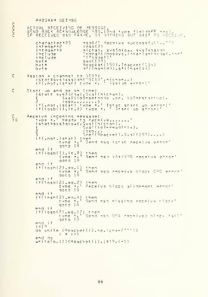
c10
PROGRAM GET^SG
ACTUAL RECEIVING OF MESSAGE.SEND BACK ACKNOWLEDGE M SO. (2nd tvoe field=FF n«x ) .
IF RECEIVED BAD PRA^E, DO NOTHING BUT WAIT TO RECEIVE
character*?^i n t eqe r * 2
incluieincludebvt eb v t ebvt?
71 s a t / ' Receive successful 1 y •* ' /
i o s o ( 2 )
nic^an* svs!oio^» svsBassiqn'-nraO: (nossys.inte r
l an] nidef . for'' fSiodef )
•
oad(lOO)Roacket(t50J,Toacket(136)^f i 1 nam(a0 ) , sf i I n^Tif aj)
Ass i an ^ channel to vi I A :
istat=svs ^assianf * N I A ' ;nicn^n» » )
i f ( .not .isMt- ) tvoe * /' ^ s s i 3 n error!'
Start jo and ao on line:istat= sys^'iiow(;°cval(nicTan)r1 %val(ioB<-set^oie .or. io?n«-startuD)#2 iosb> m i f m > )
if(.not.istat) tvoe * » ' I s t a t start uo enroll'if(iosb(l).1t.0) fyoe * t
' Start u d error!'
Receive inco^ina tessaae:tvoe * f
' Ready to receive '
istat=sys$qio*(r%val fni:han) ,
1 %val(io$«-readlb1k),2 i oso f , ,
3 %ref (Roac<et ) ,%val (150) , , , , 3
i f ( . n o t . i s t a t ) thentyoe * r ' Send nsg i s t 3 1 receive error'qot o 1
end i f
ifCiosb(l).lt.O) thentvoe * t
' Send tist V a x / V M S receive e r r o r'
aot o 10end ifif(iost">(2).. ea.l) t^?n
tvoe *r' Send n s a receive block CRC ° r ra r'
QOtO 1
end i f
i f ( i osO
(
2 ) . eq
.
2 ) thentvoe **' Receive dlock alion-nent »rror'ooto 10
end i f
if(iosb(2)»ea.4) thentvoe */' Send t^so ^issina receive block'goto i
end ifi f ( i osb
(
? ) .ea. 1 7 ) tnentvoe * r ' Seno -nso y l received o 1 o c < fail'qoto 10
end if
do Aihile ( Roac ket ( i ) . ne . i c har f • * ' 1 )
i = i +1end dowr i t e (6 , 1 1 ) ( Roac ket ( j ) * j = 1 9 ,
i - 1
)
86


1
1
c
t yoe *
/
' ,<i >al )
Rf?cei ved sue cessf u 1
1
issi in destination addressToacket ( 1 )='02' x
Toacket (2) = ' 07' x
Toacket (3) = '01 »xToacketf'J):R D3C^t(U)Toacket(5J=3r>acket ( IS)Toacket(b)=»oacXetn6)
issiqn tyoe field:Toacket (7) = ' 00 ' x
Toacket (8)='FF ' x
i indicate r h a t if isi ac^nowledae si anal
a t e s s a a e
D ut data into transmit oac<e*":
do t=l/23Toacket ( j ) = i c ^ a r ( -n s q 1 (i : i ) )
i= j H
end do
T r ansm it Docket:istat=svsSaiow(,1
23i f
(
iosbf 1 ) . 1 t .0)
% y a 1 Cnichan),% v a 1 (io$«"writelblk)»i oso t t ,
%reHToacket),%val CI 3b) / , , , )
call lio5st on (JivalfiosoCl)))t yc! ^cknowle"iae is b e i n a transmitted
%val f i o<-«-l t ds ) ,
Load transmit data and send:istat=sys$oio*(#%val ( n i c h a n ) ,
1
2i f
(
iosb( 1 ) . 1 t .0)i f ( i osb ( 2 ) .ne . )
goto 10end
i oso /
t voet voe
, , )
Fther xt itControl }
e
rerror:xm i t e r nr i '
87


PROGRAM U p LOAO
ACTUAL RECEIVING OF FILE.DISCARD LAST F^A^E.CHECK FOR 1 RECOPD p ILE.SEND BACK ACKNOWLEDGE ^SG.^nd tyoe field=FFIF RECEIVE BAD FRAME, DO NOTHING PUT wAIT TOSAME FRAME AG* IN.
hex ) .
RECEIVE
character*? '4
i nt eqer *<?
i n t eqe r * 4
inc'udei nc 1 udebytebytebyte
m s a 1/
' Received successfullyiosn(<?),donen i c h a n , sysiioio*, sysSassiqn' «- d r a : tnnssvs.interl anl nide' CSiodef )
'
oad( 100)Roacket ( ISO ) , if i l nan( 40
)
Toacket C 1 36)
f . for
Assign a channel to N I A :
istat=svsSassion( ' N I A ' ,nicn?n, , )
if(.not.istat) call 1 ibisfoof'^ai (istat))
52
C77
C1020
Start ud and no on line:i s t a t = sys$qiow(/%val (nichan),1 Xval(io$**setTiode .or. io^^-startuo),2 iosbr MMMr )
if(.not.istat) call Hb5stoo(%vaHistat))i f
(
iosb( 1 ) . 1 t .0) call H b$s t oo ( %vaH i osb U ) ) )
if(iosb(2).ne.0) tyoe ^'Controller Start ud error
Initial i 7 edone=0
f 1 ao:
Interact with user:tyoe *f* Destination filename?'read(5»52) 1 n , d f i Ina-ndf i 1 nam( 1 n+1 )=0format ( q » 4 a 1
)
ooen(name=dfi lnan/uni t=2»opqanization=' sequent
i
1 tyoe =, new' /Carriaqecontrol:' 1 ist '
, i o s t a t = i o :: pp = 7)not
o
10t yoe * ,
call 1 i bSst on (%va 1 ( i os ) )
goto 2
Ooen file f ai 1 I T a q a i n
Rece i vet yoe
filee zdv to receive
istat=svs$qiow(»%va) (nichan)1 X v a 1 ( i o2 i osn f , t
I
if(.not.istat) ci f
(
iosb( 1 ) . 1 t .0)i f(iosn(2).ne.O)i f (Roacket ( 13)
.
wri t a
(
2 t
d o n e = 1
qot o 40end i f
i f (Roacket ( 18) .eqdone=
l
/ / )
S«-r°ad 1 b 1 k )
%re'(Roack»t),%val (ISO),,all lib?stoo(%val(istat))call Hb$stoD(%vaT (iosbd )))tyne * r
' Conf ^ol 1
ea.'OF'x) then •
S50) (Roacket ( j ) ,
j
= 19
Receive error1 record file1 46)
FF ' x ) then
89


55H
C40
QOfO d
write(2,550)(Roacket(j), i=19fomat ( I28al )
Assiqn destination address:Toacket ( 1 ) = • 02' x
Toacket (2)=' 07'
x
Toacket (3)=' 01'
x
Toackef(4)=Roacket(14)Toacket (5)=Roackef( 15)Toacket (o)=Roacket ( 1 o
)
! 'J 6)
Ass ion tyoe field:Toacket (7)=
'00
'
x
Toacket (8)=*FF'xindicate that it- isacknowledge sianal
Tie s s aae
Put lata into transmit o a c < e t :
I=<?do i =1 ,24
Toacket ( j ) = i c h a r ( t s q 1 c i : i 1 1
} = j+lend do
T ransm i t oac ket :
istat=sysSaiow(r%val (nic^an)/1 %val(io?*-wrifelolk),2 iosb»;/3 %ref(Toacket),%vain3o),,,,)i f ( i osb( 1 ) . 1 t .0) call I ibSstoofXvaUiosod)))tyoe * i
' Acknowledge is oeinq transmitted....
Load transmit data and send:istat=sys5oio*(r^val ( n i c ^ a n )
,
1 ZvaHiot-«-ltds)»2 \ OSb i t t t t r r
i
)
i f ( i osb( 1 ) . 1 t . ) t yoo *, '
30
\ f ( i osb(2) ,ne • ) tyoeif (done.eq.l) qoto 30aoto 20
Ether xmifControl ler
error:xmit error
closeCuni t =2
)
tyce * , * Receive connoleteocall exitend
89


PROGRAM DOWNLOAD
ACT'JAL TRANSFER F I IE / I M TER AC TT JE .
RETRANSMIT SAME FPA-'E IF MO ACKNOWLEDGE IN S SECABORT TRANSMISSION IF NOT RECEIVE ACKNOWLEDGE [N 1) SEC
C10
11
externali nt ^oer *?
i n t ege r *'*
includeincludebytebyteby t e
aborti o s o ( 2 ) > a d d r , count, donen i c ^ a n , s y s c a i o * » sys1>assiqnt i me ( 2) fsvst i ne ( 2 ) * sec (2
)
'(•iraO: (nossvs.interl an J ni d°• (Siodef )
'
oad( 100)Toacket (H6),?fjl nam( 4 ) )
Roac'<e«- (ISO)
for
Ass ion a channel to NIAO:i stat=sys$assign( 'NIAO' f n i c h a n , , )
if(.not.istat) call HbSstoD(%valCistat ) )
Start uo ano oo on line!i S t a t = svsSqiow(f%val ( n i c n a n ) ,
1 ''SvalCiof^set-node .or.iosb» » Mf »m )
i o$Ti<-startuo)P. i osb » i t t t 1 1 t J
i f ( .not . i st at ) call 1 i b 5s t on ( X v a l (i s t a t">
)
i f ( i o s b ( 1 ) . 1 t . ) call Hb$stoo(Zval(iosb(if(iosb(2).ne.0) tvoe * r
' Controller Start1) ))uo error
Assign destination a i dressToacket ( 1
)=' 02'
x
Toacket C2)='07'xToacUt C 3 ) = '
1' x
Toacket (4)=' 00'
x
Interact with user:t y o e * f
* Select Nettyoe * , ' -'OS Syste-ntyoe *,
' ^OS Systemread(3» 1 1 ) a dd rformat ( a 1
)
i f ( addr ,ea. '
1' ) th
Toacket ( 5 ) =
Address of- U - A :
0-0 3-EA :
0.t V D - " 1 " '
t V O a " 2 " '
e i S!
e 1 Si
end
ni
Toacket (o) = ' A
f (addr.eq.'2*
)
Toacket (5)=' 03Toacket (6)='EA
qoto 10
' X• X
tnen' x' x
i f
Assian fyDe field:Toacket (7)= ' OF •
x
Toacket (3) = ' 00' x first frame recin( Q )=0 h ex
I n i t i adon
i z e f 1 a a :
=
C Interact with user:20 tyoe **' Source filename
reaci(5>22)ln,sfi 1 ^amsf i 1 nam ( 1 n+ 1 ) =0
-? •
90


22
C30
33ao
f OPTtat ( o, 40a 1 )
ooen(name = sfi Inan »uni t = 1 , nroanizet ion='seauent i a 1
1 » tvoe : 'oli' fC3rriaaecontrol=' 1 ist
'
>err: ;)
aoto 30t yoeaoto
* ,
20such f i 1 e 1 Irv aaa i n
Transmit o a c k e t :
c ount =0read CI , 3 3 , iosfat=ios,end=l0 0,epp=10l)1 C Td3c ket C j )
formatC 128al)i s t a t =sy s So i ow
(
1
?3i f
i f
t voe
Load
1
2i f
i f
c a a i t
C 3
ca
c rtai t
caca
c vai t
caca
i osb ( 1 )
i osb (2 )
1 t
ne0)0)i s
j=<?, 136)
%val(nichan),%val ( i o$«-wr i t el o 1 k )
i osb/ f f
%pefCToac<et),%call ! i b$s t oo
(
t voe *
oeioq
7 3 1(13 6),,,,)%val(iosb(n))
, 'Control 1 e r T ^ 3 n s m i t
transmitted '
arror
r a n s m i t lata and send file:at=svsSaiowC,*val (nichan)*
%va1 ( i o*-«-l t ds ) ,
ioso,, ,,,,,,)i osb ( 1 ) . 1 t .0 ) t yoeosb(?).ne.0) tyoe
System x
m
j t eTor!Controller < m i e r r o ^
or 20 seconds and 3 b o r t :
svs?ointim('0 :: 30.0', sec)sys5setimr(, sec, abort, )
op 10 seconds and abort:sysSni nt i m( '
: : 1 . • , t i me
)
sys5setimr(P, timer/)
or 5 second and retransmit:sysTbi nt i m (
' : : 5 . , s y s t i ne
)
svs'Sseti^r(l,svstime/,) i
1 wait foracknowledge 5 sec
Receive acknowledae:istat=svs5aio«Cf^val ( o i c h a n )
,
1 %va1(io$«-readlblk),2 i osd , ,
,
3 Xref (Roac*et ) f %val ( 1 SO ) , , , , )
101
Check the second tyoe Held if : FFif ( Roacket ( 1 o ) . eo. * FF ' x ) then
call sys Be an t i m (, )
Roacket ( I S) = » 00'
x
i f ( done . ea . 1 ) goto SOToacket C 3 ) = * 1 'xaoto 3
end i f
if (count. ne. 2) thencall svsS^ai f f r( 1
)
COunt=count+lq o t o 4
eng i f
call svsSwai tfr(P)call exitcall lib$stoo(%val(ios))
i e x
cancel timerclear flag
mi idle frame
91


C Assign value to end xessaqe:100 do i=9,13o
Toacket (i )= , 32 , x
end doToacket (8)='FF ,
x
done = 1
qoto JO
50 tyoe *f' Transmit co^oleted'c 1 ose ( un i t = I )
got o 1
end
I blank c H a r
1 1 as t f r a Tie
ccccccccccccccccccccccccccacccccccccccccccccccccccccccccccccccccc
SUBROUTIME ABORT
wri te(fe* 222)222 format (' ^oort Transmission')
call exitend
92


APPENDIX C
ETHERNET SOFTWARE PROTOCOL SOURCE CODE
This is the actual source code which is developed to
meet the principal gcal of this thesis. This program is also
available in VAX/VMS public user account under file name
"ETHERNET. FCE".
93


PROGRAM ETHERNET
ACTUAL RECEIVING OF MESSAGE.SEND BACK ACKNOWLEDGE *SG.(2nd tyoe field=FF hex).IF RECEIVED rtAD FRAME, DO \JOTHING BUT >IAIT TO RECECHECK AHAT 13 THE REQUEST FROM MOS SYSTEMIF THE REQUEST IS ' D • , CALL UPLOAD.IF THE REQUEST IS • !', CALL DOWNLOAD.
VE
character*^character*??i n t eqer *2inteqer*^i nt eqer * Uincludeincludebyt ebvt ebyte
msql/' Receive successfully.m s g6 / ' 'Jnreconni zed file tyoei o s d ( 2 ) t f i
1
tvoerexecsystiTieCS)* t i m e ( 2
)
nichanf svsTqiowr svs Session' <-dra0 : rncssvs.interlanloidef' (Sioief )
'
oad( 1 00)Roacket(lS0),Toacket(135)d f i 1 n a* ( -4 ) , s f i Ham(40),ft(3)
• /
for
r
ToAssign a channel *" o
v
l I A :
ist3t=svsSassiqn( *"^i I 4 * n i c i an
if(.not.istat) call 1 i b E s t o o ('£ v a 1 ( i s t a t ) )
Start uo and qo on line:i s t a t = sysSaiow1
2 i osb t
,
i f (.not .i stat )
i f ( iosbd ) . 1 t .0
, % v a 1 fnichan) ,
%val(io$«-set-node .or. io$m«-startup)*
all HbSstocfUaHistat))call 1 i bBstooCXval ( i oso ( 1 ) ))
C150
Receive incomina Tiessaae:t yoe * ,
' Ready
then\J A X / V M S
i s t a t =svs Sai ow
(
1
23if(.not.istat)
t voe * t
aoto 1
end i f
i f
(
iosb( 1) . 1 t .0t yoe *
,
qot O 1
end i f
if(iosb(2).eo.lt /oe * ,
qoto 10end ifif(iosb(2).ea.2
t vDe * t
qoto 1
end i f
i f ( iosbf 2) .ea.at voe * t
aoto 10end ifif(iosb(2).eq.l7) tnen
o receive Tiessaie% v a 1 (oichan),%va 1 ( i o£«-readl b 1 k ) ,
i osb , ,
,
Xref (Roacket ) , %val ( 150) , , , , )
henIstat receive error'
receive error
thenReceive block C'JC. error*
thenReceive block a 1 i a mien t error'
then71
i s s i n q receive clock'
end if
t yoe * ,
aoto 10DMA received block fail'
94

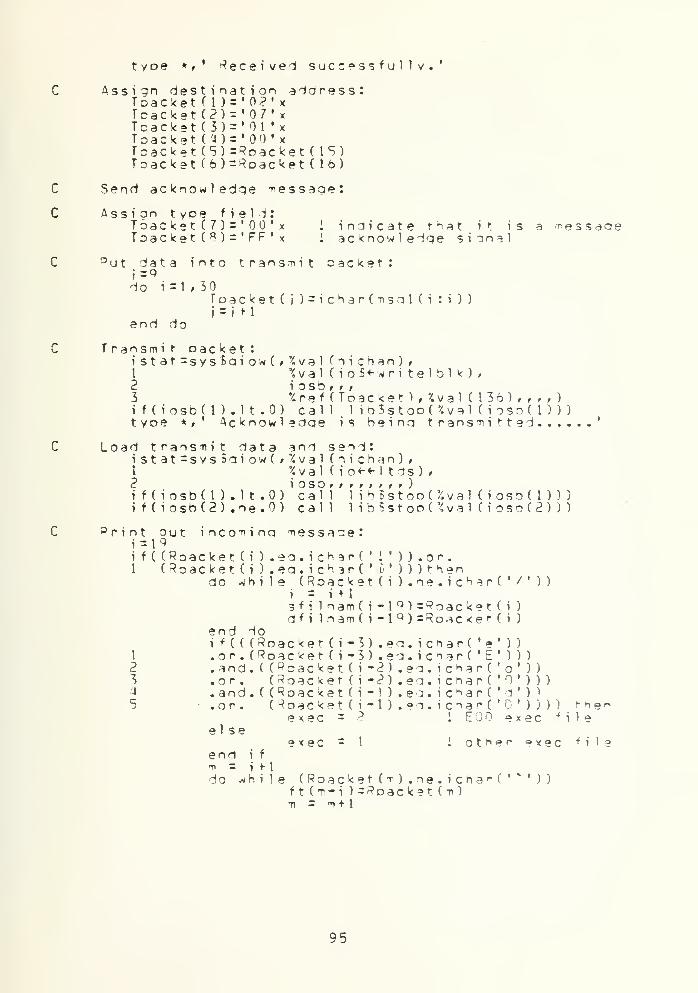
type *»' deceived successfully.'
C Assign destination address:TSacket ( 1
)=' 0?'
x
Tcackat (?) = ' 07' x
Tcacket (3) = '01 ' x
Toacket(a)='00'xToacket (5) =Rnacket (IS)Toack9t(6)=Roacket(l6)
C Send acknowledge message:
C Assign t y o e field:T6ack9t(7)='00'x I indicate t H a t it is a ^ e s s a a eToac ket ( * )
=' FF • x i acknowledge sianel
C D u t data into transmit oacket:i=9do i = t , 30
Toacket(j)=ichar(nsgl(i :i ) )
i=
iM
end do
T ransm i t oac ket :
istat=sys£giow(,t
23i f (iosb( 1 ) . 1 t .0)
%val(nichan),%val(ioS<-writelblk),i oso , , ,
%ref(Toac<et),*4val (136)/,,,)call 1 i oSstooC fcval ( i oso( 1 ) ) )
t yoe * r Acknowledge is being transmitted
Load transmit data and send:istat=sys5giow(,%val (nichan),1 %val ( io«-«-l tds) /
2 J OSb i p t t t r t r )
if(iosb(l).lt.0) call li^Bstoo(%val(ioso(l)))i f ( iosb(2) .ne.O) call 1 i b*s t on
(
X va 1 ( i oso ( 2 ) )
)
Print out incominq m e s s a a e :
1=19i f ( (Roacket CO .ea.ichar( ' J '
) ) -or.1 (Roacket(i).eg.ic^3r('i')))then
do while (Roac ket ( i ) . ne . i cH ar C ' /'
i = i f 1
sfi lnam(i-19)=P?r5acket(i )
d f l lnam(i-l q )=Roac<et(i )
end do
) )
1
234
5
other
^ h i (Roacket (t) . ne • icha^C '
f
t
(m-i ) =Roacket (m)m = m+ t
95

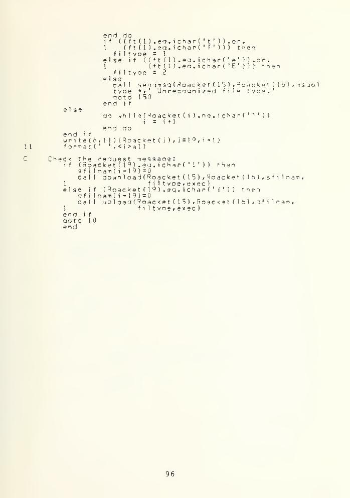
end doif ( ( f t (1 ) .en.i chart •
t' ) ) .or.
1 ( f t C 1
)
.ea.ichar( 'T
' ) ) ) thenf i 1 tyoe = 1
else if ((*t(l).ea.ich3r('e')).or.1 ( f t ( 1 ) .ea. icharC 'E ' ) ) ) then
f i 1 t yoe = 2
else
ket (15)
,
J oacL
i 1 e t yoe
.
S3cal 1 sendt»sg(Roacket ( IStyoe * t ' Unrecognized f
goto 150
. ichar( '
* ')
)
end do
ket ( 1 b ) , -ns ::n )i
1 1
C
end ifwritef6»ll)(3oackef orrat (
''
, <i >al )
oac ket ( i ) . n= 1+1
t ( i ) , i= \ 9 , i - I )
96


c
22
SUBROUTINE 0OwNL0A0(plS,rl6,sfiHafP,filtyDe,*xec)
ACTUAL TRANSFER F ILE
/
INTER ACT IV E
.
RETRANSMIT SA^F FRA^E IF NOT RECEIVE ACKNOWLEDGE IN 5 SECABORT TRANSMISSION IF \QT RECEIVE ACKNOWLEDGE IN 10 SEC.
character*??character*??i n t eger *2integer*?i nteaer*^!integer***integer*<4includeincludebytebytebyte
t s a 2 / ' No suc^ file! Try a o a i n . '
/
t s n 3 / ' Abort Transmission. * *
/
i o s b ( 2 ) f addrfcount »donefilt yoe » e xec r nr>a <
nic^tan, sys$giow# svs^assi ins y s $ b i n t i m , sys*seti-nr, sysDwait frt i me ( 2) r sys t i -ne ( 2 )
'"IraO: (nossys.interl snlnidef .for'' (Jiodef )
'
oad(100),sendrec(S12),sendrecl(10 2a)Toac<et(l}6),sfi 1 n a ^ C '-i )
Roacket(150),rl5#rl6
issi on a channel to N I A :
i stat=svs£assiqn( • M I A ' , n i c h a n , , )
if(.not.istat) call lih$stoo(%va1(istat))
Print out
:
tyoe *f' Reauest fansferrina of file'
p r i n t Mlena^e:write(6,22)(sfi lna-n(<) ,<=U IS)format (
''
, ISal )
tyoe * /' to M S system at address:02 07 01 00',
1 r 1 S , r 1 b
Assign destination address:Toacket ( 1 ) = '02'
x
Toacket (2) = '07' x
Toacket (3)=' 01•
x
Toacket (4) s' 00'
x
Set the address of reauest ina station:Toacket (5)=r ISToac k et ( 6 ) =r 1
6
As s i on t yoe f i e 1 d
:
Toacket (7) = ' OF' x
Toacket (8) = ' 00' x
Initialize flaa:done =
first frame
d e n file:ooenfnarne^sfilnaTi runit = l/organization=' sequential '
1 ,tyoe =, old , rcarriaoecontrol = , Hst , ,err = 9')
Pi 1 e tyoe check coint:
if (filtvoe.ej.l) tnenqoto 30
elseooto ?00
end i t
97


c30
33
U0
ODen file error hen-ilina:call senctmsg ( r 1 5 , r 1 6 , usa^ )
t yoe * t
returnno such file! Try
1 no suchao3 in.'
file try 3:ain
Send text file:count =0r e a d ( 1 ,33, iost3t = ios,en-i=1001 C Foac<et ( j ) , j =9, 1 36)for^atf 123al)Toacket(135) =Foacket ( 1 36) =
i s t at =sy s $qi o* (
1
23
i f ( i o s b ( t ) . 1 t .
i f f i osn ( 2 ) . ne,
' File
err=1 1
)
<CP><LF>
) ,
t yoe0)i s
04 ' x00' x
%val(nichan),% v a 1 ( i o 5 «• w r i t e 1 o 1
'<
\ OSbr t
i
%ref(Toac*et),%val(13to),,,,)call lib$stoo(%va1(iosb(l))call Hb$stoo(%val (ioso(2) )
Deina transmitted '
Load transmit dataistat=svst>aiow(,1
2f f CiosbU ) .1 1 .0)if(iosb(2).ne.O)
and send file:Xval(nichan)/Xval(io«-«-1 tds) ,
i OSD , f i t t t r r )
call lib * stool" %val(iosb(l)))call 1 i bSstooC '/.val ( i oso(2) ) )
/Vait for 15 seconds and abort:stat=sys$bintim('0 ::15.0*,time)f(. not.
i
stat) call lio$stoo(%val(istat))stat=sys1iseti.Tr( JWal (2)r%re -f (ti'ne)rf )
f(.not.istat) cal HbSstooCXvaHistat))
Na i t
*ai f forS sec .
deceive acknowl elaei s t at =s v s So i o* ( ,
1
23i f (iosb( 1 ) . 1 t .0)i f ( i o s o ( 2 ) . n e . )
''. v a 1 (nichan),% v a 1 (ioBt-reaolblk),i oso , ,
,
% r e f f *d ac < e t ) , % v a 1 M 5 ) , , , , )
call 1 i bis toot Xval ( i oso( 1 ) ) )
cal 1 1 ibSstoo(*<val ( i o s o ( 2 ) )
)
Check the second tyoe field if = Fl
if (RoacketClSKeq.'FF'x) thencall sys.'Bcantim(f) 1
»oacket ( 1 8)= '00
' x !
i f (Tone.ea.l ) ooto 5Toacket ( 8 ) = * 1
fx I
a o t o 3end i f
if (c oun t . ne . 2
)
hex :
cancelclear
m i dd 1 e f r a^e
t i tiersflag
en i f
l.mc.i-j t^encall sysSwaitfr(%val(l)lC oun t = c oun t + 1
qot o JO
call sysSwaitfr(%val(2))
98


anort transmission
101
c100
call sendmso ( r 1
5
, r 1
6
, ms q3
)
tyoe *#' Abort trans-ni ssion. '
returncall 1
i
b5stoo(%val ( i os )
)
Assi in value to m e s s a q e of the last f r sue
:
do i=^,13oToac ke t ( i ) = ' 32 ' x 1 hla"< ch^r
end doToacket (%)= % FF*xdone = 1
qoto 40
1 1 as t f r ate
C200
222
333
300
Send e xecuif ( exe
1
for"n a x
• i f
rag1
'
formaxi f
1
1 s
endk =
t ablc.eqn(\,
( semat (
= 5(exe0(1,(se
ma t (
= 9
e file:. 1 ) t hen222, iostat=ios, end =500, err=2 2)ndrec(j)rj =1*512)5 1 2 a 1 )
c.eo.2) then333»iostat=ios»end=500,ndrec 1 ( i
)
, j = l , 1 02a
)
1024al )
rr=202)
400
count =
do 1 =
i f
e 1 s
endend doi s t a t = s1
23i f ( i osoi f ( i o s bt yoe * ,
1 , 128(exec.ea.l) t nenToacketd+8) = sendrec ( k * 1 28- ( 1 23- 1 ) )
e if (exec.ea.2) thenToacket(l+8) = sendrec 1 ( k * 1 28- ( 1 28- 1 )
)
i f
ys?qiow(/%val ( n i c h a n ) ,
% v a 1 (in5*-writelol<)»i osb , ,
,
%ref(Toacket),r>/al (136),,,,!(l).lt.O) call 1 ib?stoo(%val ( ioso( 1 ) )
)
(2).ne.0) call 1
i
oSs t oo ( %v a 1 ( i oso ( 2 ) )
)
' FHe is neing transmitted '
l n a n o s e n . i fileow(»'Zval (nichan)4vai nicnani,
%val ( io«-«-l tds) f
} osb 1 1 1 1 1 * 1
1
)1
1 1 ibSstooOWal (iosb( 1 ) ) )
1 1 ibSstooC J/
.val ( i oso(2) ) )
cal 1
cal
Load transmit dataistat=sys£qi1
2i f (iosb( 1 ) . 1 t .0)if(iosb(2).ne.0)
^ a i t for 15 seconds and abort:istat=sysibintim('0 ::15.0',ti-ne)if(.not.istat) call HbBstoo(%val(istat))i st^t=sysBsetimr(%val ( 2 ) , % r e * (t i "i e ) , , )
i f ( . not. S stat) call HbSstop(%va1(istat))
^ a i t for 5 second an?l retransmit:istat=sys5bintim('0 ::5.0'fSvstime)if(.not.istat) call Hb?stoo( a'.va1(istat))istaf=sysheH^r(';val (l),/,ref (svstiTie)f >)if(.not.istat) call I inistoo(?val (i stat) )
wait for5 sec .
99


202
C500
50
deceive acknowlelae:i 5t3t=sys5qiow(/'4val (nic^an),1 %val ( i o$<-read1 bl k ) ,
2 i osb# i t
3 '/.ref (Rnacket ) ,'ival ( 150) , , , , )
if(iosbU).lt.O) call 1 it5stoo(Xval (iosod ) ))if(iosb(2).ne.O) call HbSstoo( v.valHoso(2)))
Check the second tyoe field if - FF hex:if (Roacket (13) .ea. 'FP'x) then
c ance 1 timers.clear f 1 aq
twiddle frame
call sy secant i m (,
)
Roacket ( 18) = ' 00•
x
i f ( done . ea. I ) loto 50Toacket (8)='01 '
x
k = k + 1
if ( k . ea .max) thengoto 200
elseaoto 30
end ifend i f
if (count. ne. 2) thencall svs$«/aitfr(%val(l))COunt=count + 1
goto 400end i f
cal 1 svsS^ai t
f
r(%val C2)
)
call send.^si(rl5f rlb»iisa3) I abort transmissiont yo Aborf transmission.returncal 1 1 io$stoo(^va! (ios))
Assign value to message o * the last frame:do i = 9 f 1 3
6
Toacket ( i)=' 32
' x 1 nlank charend doToacket (A)='FF '
x
! last framedone = 1
goto 400
tvoe *,' Transmitc 1 o s e ( u n i t = 1 )
returnend
omol e t e d
'
100

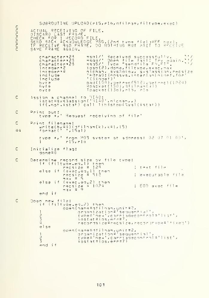
ccccccc
SUBROUTINE UPL0AD(rl5,rlb,nfi lnam, f i 1 t yoe, exec )
ACTUAL RECEIVING OF FILE.DISCARD LAST FRA^F.CHECK PQP 1 RECORD C ILE.SEND BACK ACKNOWLEDGE ^SG.(?nd r y n=? field=FFIF RECEIVE BAD FRAME, DO NOTHING BUT /'AIT TOS4viE FRAME AGAIN.
hex ) .
R E C E T >/ E
c *ar ac t e r *2 3
character*??charac t er *25n t e cj e r * 2
ncludencluie
bytebytebyte
' /• /' /
m s g 1/
' deceived successful 'v.m s a 4 / ' Ooen file fail! Trv ^ a a i n-nso5/' Tyce "sendfile FN. FT".i oso ( ? ) , done , f i 1 tyoerexec,maxn i c n a n f sys$qiow# svstassiqnr recsize' «- d r a : fnnssvs. i n t e r ] a n 1 n i d e f . for '
' (Siodef )'
oad( 100 ) , get rec f 51 ? ) , aet nee 1 ( 1 02a)Roacket ( 150 ) , -if i 1 na* (40)Toaci<et(13o),rl5, r I 6
Assign a channel to N I A :
istat=sys$assian( ' N I A ',
n
i c h a n * , )
if(. not.
i
Stat) call 1 i b 6 s t o o (J
4 v a 1 ( i s t 3 r ) )
°rint out:tyoe *f' Request r e c e i v i n a of file'
C
aa
C
C
°rjnt f i
writeforma
t yoe1
Initial i
done =
De t e rrn i ni f ( f
else
el se
end i
Ooen newif ( f
1
23a
else
1
23
end i
1 ename :
(6,44)(dfilnam(k),k=l,15)t
('
'
, 1 5a 1 )
*,' from M 3 syste-n at aioressr\Sr r 16
2 7 1 0',
z e flag:
e record size ov file tvoe:iltyoe.eq.l) tn a n
recsize = 12^ I t°xt fileif (exec.eo.l) tnen
recsize = 51? 1 executable filemax = 5
if (exec.eo.2) thenrecsize = 10?
4
1 tOD exec filemax = 9
f
file:iltyoe.eq.2) then
ooen(name = dfi 1 n ^ -n , u n i t = 2 /
o r q a n i z a t \ o n = ' s eau e n t i a 1'
t
tyoe-' new' »c3rri aaecontrol^' 1 i s t '>
iostat-i os , e r r = 7
,
recordsi z e = r e c s i z e > recoritvoe = '
f i x e d ' )
ooen(name = dfi 1 n am , un i t = 2
,
oraanizat ion^'sequent i ^1 ',
tyoe = ' ne*
'
> c ^r r i a o e c o n f r o 1 = '
i ost at = i os , er r = 7 )
i st
101


goto 90call sendmsa ( r 1 5 , r 1
o
, nsa4
)
tyoe * ,' Ooen file f a i 1 1 Try
returnlaain
C90
20
file:sendmsq(rl5, r 1 b * 71 s o 5 )
*f' Send instruction ti e s s a 3 ef ^eady
sys5qiow(
to receive file
55
Pece i vecal 1
t yoetyoek = 1
i s t a t
1
23i f ( i o s b ( t ) . 1 t . )
i f ( i osb(2) .ne.O)i f (Roacket ( 1 ^ ) .
wri t e(2/55 ) (Poacket ( j )
format ( 1 ?8a 1
)
•ione= 1
(Roac*et CIS) .en. 'FF'xDdone=
1
)
se
end
if
i f
%va 1 ( n i c h an ) ,
%val ( iof«-readl hi k
10SO(MX re f C Roac ke t ) , %vaH 1 50 ) , , , ,
)
call HbBstoo(^val(iosb(l)))cal 1 1 ib$stoo(%val ( i o s o ( 2 ) ) )
en.'OF'x) t h p n 1 a 1 recordj = 1 9 , 1 '4 6 )
Men
f i
Send acknowledge
C60
Assign destinationToacket ( 1
)=' 02'
x
Toacket (2)=' 07'
x
Toacket (3)=' 01 'xToacket (4) = • 00 ' x
Toacket (5 ) =r 1
5
Toac ket ( 6 ) =r 1 b
message :
Jdress :
Assign tyoe field:Toacket (7)='00'xToacket (8)='FF •
x
i messagei acknowledge signal
Put data into transmit oac<et:'= 9do i =1 ,28
Toacket ( j ) = icnar(-nsgl ( i : i ) )
J*= j + 1
end do
Transmit d a c k e " :
istaf =sysSqiow(/1
23i f ( iosbM ) . 1 r .0)i f
(
iosbf 2) .ne.O)tyoe */' Ac< now 1
%val (nichan),,
"i v a 1 CioS<-writelb1k)/i osb t t ,
%ref(Toacket),V/al ( lib) , , , , )
call lib1>stoo(%vaHiosb(l)))cal 1 1 ih.Bstoo( J<val f i o s o f 2 ) ) 3
edoe is beino transmitted....
Load transmit dataistat=sys$oiow(,1
2i f (iosbC 1 ) . 1 t .0)i f(iosb(2) .ne.O)if ( ( done . eg . 1
)
and send :
% v a 1 (nichan)*%va I ( i o«-«-l t 1s ) ,
lOSOi » m m ; » )
call 1 i bSstoo ( val ( i oso( 1 ) ) )
call Hb$stoo(%val ( i oso(2) ) )
and. (<.ne.max) .and.
102


1 (filtyoe.eo.2).and. (exec.ea.l)) t^enwr i te(2, 555 ) (ge tree ( j )» j = 1 # (128* (k-1) ))goto 70
els? if (done.eg.l) thenaoto 70
end if
C Nrite to record every g f t e r recei vina '-I or fl frames!if (filtyoe.eo.2) then
do 1=1 , 128if (exec.ea.l) thengetrec(k*!28-(128-1
)
)=Roacket (1 +18)else if (exec.ea.2) then
aetrecl(k*12fi-(128-l))=Roacket(lM :>)
end i f
end dok = k + 1
if (^.eT.i3«) thenif (exec. en. 1) then
w r i t e ( 2 > 5 5 5 ) (getrecCj ) t j = 1 * recsi ze)5 55 format (512a 1)
else if (exec. eg. 2) thenwri t e ( 2 f 7 7 7 ) (qet reel C j ) , j =1
,
recsi ze)111 format ( 1024a 1 )
end i f
k = 1
end i f
else if (filtvoe.ea.l) thenwrite(2,666)(9oacket( j), j = 1 9, 14 6)
666 format ( 1 28 a l
)
end i f
goto 20
70 c 1 ose fun i t =2)tyoe */ ' Receive comoletedi'returnend
103


SUBROUTINE SEND*<SG(rl5,rlo,T)sa)
C
30
ACTUAL SENDING OF MESSAGE.mMJ FOR ACKNOWLEDGE.IF NOT ACKNOWLEDGE IN 5 SEC,IF NOT ACKNOWLEDGE IN 10 SEC,
PETOANS^IT.ABORT TRANSMISSION
character^*) msai n t eaer*2 iosointeaef*y nicHi nt eae'' *4 sy s 5
i nt eae r *4 svstinclude ' <-drinclude ' ( $ i
byte oad(byte Toacb y t e r 1 5
,
(.2) , a ddr, done, countan, svsBaiow, sys?assionb i n t i m , svsfsetimr, sysSwaitfrime(2)»tiroe(2)a0: [nnssvs.interl an] nioef.for*'odef )
'
100)ket(l$6),textn?8),voacket(lS0)r I 6
Assign a channel to J I A :
istat=sys6assiqn( ' N I A * , n i c h a n , ,
)
if(. not. i Stat) call Hb5ston(?val f istat ))
Assion destinationToacket ( I )=' 02'
x
Toacket f 2) = ' 07'
x
Toacket (3) = ' 01 '
x
Toacket C4)='00'xToacket (5)=rl5Toacket (6) =r lb
Ass i qn t yoe f i e 1 i :
Toacket ( 7) = • 00 ' x
Toacket (* ) = ' 00 • x
address
: -nessaaeI don ' t care
Put data into transmit oacket:i= q
.
do i =1 ,28Toacket (
j
)=ic^ar(msq(i :i ))i = i +
1
end do
Transmit oacket :
count =0istat=svs$qiow(,%val ( n i c r, a n ) ,
1
23i f(iosb( 1) . 1 t .0)if(iosb(2).ne.O)tyoe *,' Nessaae
Xval(io$«-write1blk),i osb , ,
,
*4ref(Toacket),°4val ( I 3 n ) , , , , )
call 1
i
b£stoo(%val ( i osn( 1 ) )
)
call libtstoo(%val(iosp(2)))is beino transmitted '
Load transmit data and send:i stat=sys5qiow(,%val (nichan) ,
1 %val C i o«-«-1 tds ) ,
2 i osb ,,,,,,,,
)
i f (i osb( 1 ) . 1 t .0) call !ibSstoo(%va1(iosb(l)))i f ( i osb(2) .ne.0) call 1 i b Sst no
C
Xv a 1 ( i osc
(
2
)
)
)
y.1 ait for 15 seconds and abort:
call sysSbintimC'O : : 1 5 . ' , t i m e )
104


cal 1 svs'Jset inr(7,vgl (2),%ref(ti"ne),f)
n a i t forcall scall s
Rece ive ai st at =
1
23i f ( i osi f ( i os
Check theif (Ro
5 second an1ys'SnintimC'O
retransin t :
::5.0'/systime)vsSset imrC-ival ( I ) f^ref Csvst i m e ), , )
c know 1 edaes vs Sai ow
(
r
ret r a n s ti i t
after 5 sec
0)0)
% v a 1 (nichan),^ y a 1 (io£«-readlblk),i osh / , ,
%p»f (RDacket) , %val (150) , , , , )
cal 1 1 io?stoo(%yal ( i o s o ( 1 ) ) )
call 1 i hSstoo(%\/al ( i oso (2) ) )
field if = Ff hex
:
•FF'x) then
ne . i c ha r
(
b6
end ifi f (co
eno i f
call sreturnend
b(l).!tb(2) .nesecond tyoe
ackef ( 18) . e qi = 19do while ( R o a c k e t ( i )
i = i +1end dowrite(o,6o)(Roacket(j), 1 = 19f or-nat (
' ' , <i >a t )
call sys^c an t i m ( , ) i
Pcacket (l«)= , 00 ,x
return
unt.ne.2) thencal 1 sysSwai t
f
r(%yal ( 1 ) )
count=count * 1
goto BO
ysSwai t fr(Xval (?) )
) )
i -1 )
cancel timers
105

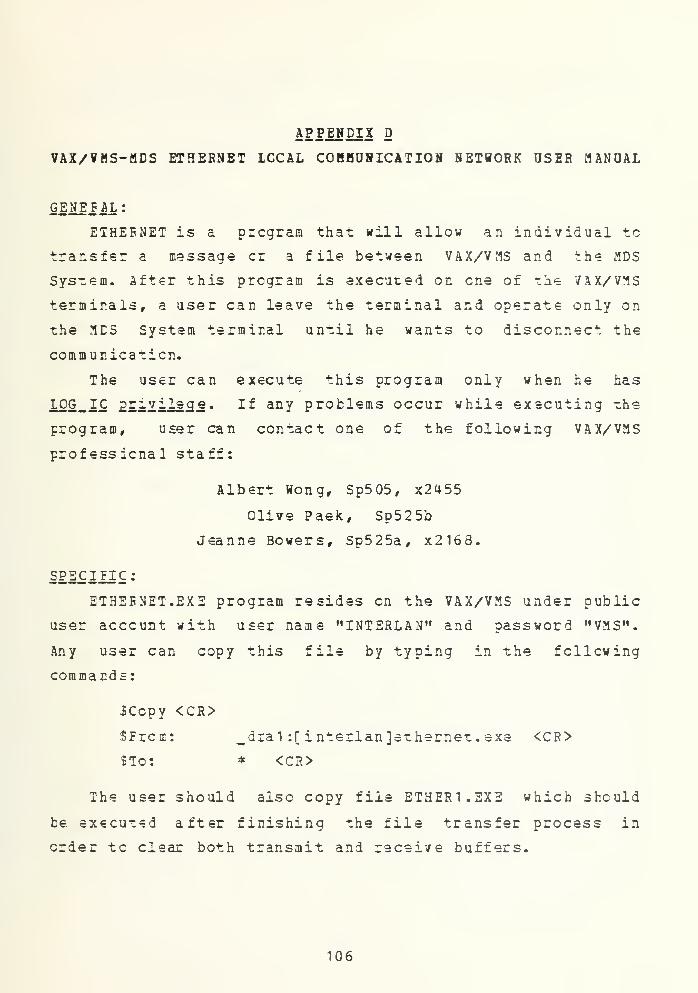
APPENDIX D
VAX/¥MS-MDS ETHERNET ICCAL COBHUHICATION NETWORK USER MANUAL
GENEJ AL :
ETHEENET is a program that will allow an individual to
transfer a message cr a file between VAX/VMS and the MDS
System. After this program is executed on one of the VAX/VMS
terminals, a user can leave the terminal and operate only on
the MES System terminal until he wants to disconnect the
communication.
The user can execute this program only when he has
LOG_IC 2£~viiec[e. If an Y problems occur while executing -he
program, user can contact one of the following VAX/VMS
professional staff:
Albert Wong, Sp505, x2455
Olive Paek, Sp525b
Jeanne Bowers, Sp525a, x2168.
SPECIFIC
:
ETHEENET.EXE program resides on the VAX/VMS under public
user account with user name "INTERLAN" and password "VMS".
Any user can copy this file by typing in the following
commands:
ICopy <CR>
SFrcm: ^dral :[ interlan]ethernet. exe <CR>
$To: * <CR>
The user should also copy file ETHER1.EXE which should
be executed after finishing the file transfer process in
order tc clear both transmit and receive buffers.
106


When these two files are copied, user can execute
ETHEFNET.EXE by typing
$r ethernet <CR>
then the message
Ready to receive message
will appear en the screen which tells the user that VAX/VMS
has teen connected to the Ethernet Local Area Network.
After this point the user can do any file or message
transfer fcy working en the MDS System terminal.
OPERATION ON MDS SYSTEM:
At the time this thesis is being written, there are 2
diskettes which contain program used to do file and message
transfer between MDS System and VAX/VMS, one diskette is to
be used with the MDS System which is connected to the single
density disk drive and it contains the following programs:
LOGON1.COM
SENDMSG1.COM
SSNDFIL1.COM
the ether is to be used with the MDS System which is
connected tc the double density disk drive and it contains
the following programs:
L0G0N2.COM
SENDMSG2.COM
SENDFIL2.COM.
These twe diskettes are now being used by Capt. Mark Stctzer
USMC, the originator of the programs in the diskettes.
Therefore, the final instructions on how to use the programs
will be found in his thesis which will be completed by
September 1S83. However, the instructions on how to trars-
107


fers file ci messages between the MDS System and VAX/VMS are
as fellows:
When the system is booted up with the above mentioned
diskette, execute L0GCN1.COM (or L0G0N2.COM if you work with
the double density disk drive) by typing
A>L0G0N1 <CR>
To transjriz a message from the MDS System to the VAX/VMS:
A> SI^CMSGJ. <CR>
ETHERNET CONSOLE MESSAGE TRANSMIT PROGRAM:
VERSION 1.11-SINGLE DENSITY: 06/10/83-MDS
NCTE:PECGRAM "LCG0N1" MUST BE LOADED PRIOR TO
RUNNING THIS PROGRAM FCR PROPER OPERATION.
IF NCT-COLD BOOT AND TYPE "LOGON 1" AND
THEN INVOKE THIS PROGRAM.
SELECT NET ADDRESS OF DESTINATION:
ADDRESS 00-04-0A( MDS SYSTEM ):ENTER 1
ADDRESS 00-03-EA( MDS SYSTEM ): ENTER 2
ADDRESS 00-07-7F( VAX 11/780 ):ENTER 3
INPUT MESSAGE (128 CHAR MAX) -END WITH ACCENT=> V
SUiJI message here.
*
SENT
A>
To tr ansa it a file ficm your A disk to VAX /VMS:
Initiate SENDMSG like you want to transmit a message as
above. Eut this time you must enter the special message as
shown belcw:
A>3ENDMSG1 <CR>
108


INPUT MESSAGE(128 CHAR MAX) -END WITH ACCSNT=> *
3f
i
lea ame . filet
y
pe/txt*
SENT
********** RECEIVED MESSAGE IS:
Type "sendfile FN. FT"
********** END CF MESSAGE
CCNNEC1ED TO THE ETHERNET-COLD BOOT TO DISCONNECT
A>SINDFiil filename, filetype <CR>
ETHERNET FILE TRANSFER PROGRAM:
VERSION 1.12-SINGLE DENSITY : 06/10/83-MDS
NOT£:FCR PBOPER OPERATION, PROGRAM "LOGON1"
MOST BE EXECUTED FIRST TO LOAD THE INTERRUPT
HANELEE INTO MEMORY. IF NOT-COLD BOOT AND DO SO
SELECT NET ADDRESS OF DESTINATION:
ADDBESS 00-04-OA (MDS SYSTEM) : ENTER 1
ADDRESS 00-03-EA (MDS SYSTEM) : ENTER 2
ADDBESS 00-07-7F (VAX 1 1/789) : EN TSR 3
3
IS THIS A TEXT FILE [5 2.5KB MAX] ( Y OR N ) = = >
Y
BEAEING THE FILE INTO THE BUFFER
REAE COMPLETE
********** FILE TRANSFER BEGINS **********
IX
109


TX
********** FILE TRANSFER COMPLETED **********
a>
12 receive a file from VAX/ VM S to lour d isk :
Initiate SENDMSG like you want to transmit a message as
above. But this time ycu musr enter -che special message as
follow:
A>SENEMSG1 <CR>
INPUT MESSAGE(128 CHAR MAX) -END WITH ACCENT=> N
!filename. f ile type/ex e*
SENT
********** FILE RECEIPT BEGINS **********
OPENING BECEIVE FILE: RECFROMX.NET
RX
RX
***** END FILE RECSIEI-SEE FILE RECFROMX.NET *****
C0NN2CIED IC THE ETHERNET-COLD BOOT TO DISCONNECT
A>
Note: Except for line spacing, the above sequences appear as
they will ax the MDS System terminal. The underlined items
are those which you must enter (in proper sequence)
.
110


Important nets:
1)Dc not forget to snd any message sent to the VAX/VMS
with accent " x ".
2) The "/txt" is used to indicate that the file to be
transferred is a text fila. The Vexe" is used to indicate
that the file to be transferred is an sxecutable file. User
must specify this indicator correctly to yield the
successful transferring of a file.
111

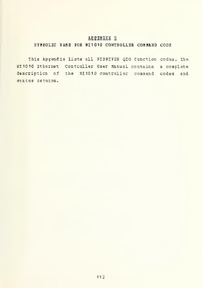
APPENDIX E
SYHBOLIC NAME FOR NI1010 CONTROLLER COMMAND CODE
This Appendix lists all NIDBIVER QIO function codas. The
NI1010 Ethernet Controller User Manual contains a complete
description of the NI1010 controller command codes and
status returns.
112

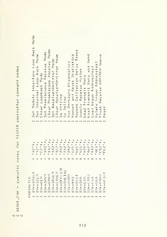
05
"Oo
cit)
Eeou
£_
O
Zcu
0)
7?O2:
-*
<J 0) in
<Q <V "D <L>
T* 0)-r-
X3O
oU
£c
u
0. o 2r a; o »- h- CD <u
C s 0) "C s m 4- 'Ti ^—
s
Do V > o u tn v J) -r*
_, -* > •^ .2. L. — •t- •*w "C —
*
<v
u — 0) o *~ t-i — L. c S) -—
•
CCV (C CD u L. L. in (0 a> CD <t 'X V) c_;
u r X' u 0> c U c 4-1 o -- ~~ en r(P "C <u cr L. uU c CO »- TJ ftJ V) 0) N,**- Q JV L. 1 a c r j- •w en <_ ac o 2 0) -i_i C (0 4-» i <n (0 U T> <!
0> c (/l ^ 1 o •- 03 ••- a Q t_ "C r— _> _* 3 o C 1 Q X 4-< 01 "C <r
c (J o u 3 <U <U tfl > 4- *->^^
a;
—
(
1
—
It 3 en 1 > "O a <5 f> >'Tl £t O ••- <D •<-
•
c — a> E e 5 -»-
c c a in E > 1' V (0 -r- — u CO uo c o (U— L. o •» O •— u c V o C o <ii c c 3 t_ u3 Hi c e c 0) a> • — c -Q 10 o cc 10 <T3 o V"C —
'
_i o n o cc — •»- 1 c_ C t_ cr
o c c_ a. ^~ — c 4- *- > f— >— LD u2 — c a. t- CC (_ •+- c Q (_ C .
—
*- jZ 4W
T T> <T3 c —_ c c T3 -Q "0 <v '/) 1'
4- 4W a; i- 0) «- 0! c c a Q (0 to fC — 3 l/l
a; 1/ — 0) — a> — o c 3 V i 3 O c o V — CD
<75 cc ^j CO u -0 u LD cj: cr X ct n _J —I _i—
U. *
oc
en
e
c
XXX----------------- - - r«j i"u f\j nj rvj r\j r\j »- — — ocooajnj
II II II H II II II II II II II II II II II II II II M
>in
I
cr
LU
<i
cc
a.
_J 21 5" 2" L»J '.J _ — C. i— 75 C? -l.1
>-i_jSa£CCOOU.-JCDCOOCQOO<*'<IXC/35:i-*-J0.Q-CCCCU_3CCCt_)CCt— I— COCSCCtu^coLiXuo)jcca:3:a:cojjjC'i.x
(_:(_) u
113

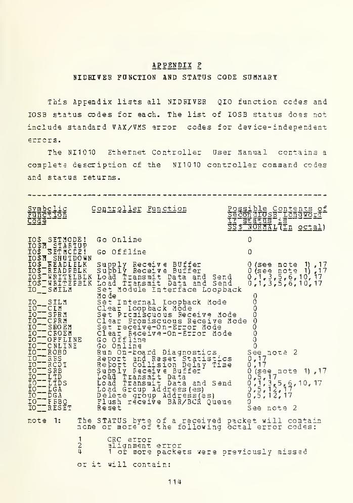
APPENDIX F
8IEBI7EB FUNCTION AND STATUS CODE SUMMARY
This Appendix lists all NIDEIVER QIO function cedes and
IOSB status codes for each. The list of IOSB status does not
include standard VAX/VMS error codes for device-independent
errors.
The NI1010 Ethernet Controller User Manual contains a
complete description cf the NI1010 controller command codes
and status returns.
Symbolic"FuncT ionCole
10$ SETMCDE!I0$T5 STARTUP10$ SETMCDE!IO$fl SHUTDOWN10$ "KEADLELKIO$"READFELKIO$"WEITELBLKIO$"WEITEEELK10 "SMILM
Controller Fun ction
Go Online
Offline
10 SILM10""C1M10""SEBM10""CPRM10""SEOEM10""CEOEM10""OFFLINE10""CNLINE10""ROBD10""RES10""RCDT10""SRB10""LTD10""LTDS10""LGA10""DGA10""EEBQ10" "RESET
Possible Conten ts ofSlconaTUSB Tong worcTn~sTaTus is53$ NUHMALlin octal)
Go
SupplySupply
Eeceiv €Receive
BUfferBuffer
Load Transmit Data and SendLoad Transmit Data and SendSet Module Interface LoopbackModeSet Internal Loopback ModeClear Loopback ModeSet Prcniiscuous Receive ModeClear Eromiscuous Receive ModeSet receive-On-Error ModeClear Receive-On-Error ModeGo OfflineGo OnlineRun On-fcoard DiagnosticsReport and Reset StatisticsReport Collision Delay TimeSupDly Receive BufferLoad Transmit DataLoad Transmit Data and SendLoad Grcup Address (es)Delete group Address(es)Flush receive 3AR/BCR QueueReset
oo
seesee1,3,1.3
notenote
1) ,171 ,17
10, 1710,17
See note 20,170,17(see note
0,5,17,1,3,5,6,
0,5,12,170,5, 12, 17
See note 2
1) ,17
10, 17
note 1: The STATUS byte of a received packet will containnone or more of the following octal error codes:
1 CRC error2 alignment error4 1 or more packets
or it will contain:
were previously missed
114


17 Non-existent memory timeout on some bufferword (other than the first) occurred whileDMAing the received packet into memory
note 2: The second IOSB longwordccmmand will contain onediagnostic codes:
atof
the completionche following
of this
success1 checksum error in local memory2 NM10 DMA error3 transmitter error4 receiver error5 looptack. failure
115


LIST OF REFEfiEHCES
1. Klinefelter, S. G., Implementation of Real- Time,Distributed Ope ratin g "*>vstem~"for a
"TTultiple CqmpuTer
Svsteni, T".~". Thesis, NavaT Tost graduate school, June,
2. Tanenbaum , A. S. r Computer Networks , Prentice-Hall, Inc.
,
Englewcod cliffs, New~Jersey, T"JH1.
3. IHTIHLAN, Inc., Concise Ethernet Specification andNI1010 [J nib us Ethernet ' Comm unications controller
,
a.
8.
INIERLAN, Inc., NI1010A UNIBUS Ethernet CommunicationsController User Manual" (MEMHHETT"^ 827
5. INIERLAN, Inc., INTERLAN NS2030 VAX/VMS (TM) DeviceDriver and Diagnostics TJser~lTar.ua 1, T98 2.
6. Digital Equipment Corporation, VAX/VHS System Ser vice sReference Manual, 1982.
7. Digital Equipment Corporation, VAX/VMS I^/O UserManual, 19 82.
Digital Equipment Corporation, V AX-1 1 FO RTRA NReference Manual and User's Guide, 1982.
9. Digital Equipment Corporation, DECnet-V AX U ser' sGuide, 198 2.
116


INITIAL DISTRIBUTION LIST
No. Copies
1. Defense Technical Information Center 2Cameron StationAlexandria, Virginia 22314
2. library, Code 0142 2Naval Postgraduate SchoolMonterey, California 93940
3. Department Chairnan. Coda. 52 1
Department of Computer ScienceNaval Postgraduate SchoolMonterey, California 93940
4. Naval Postgraduate School 1
CcmDuter Technology Curricular OfficeCede 37Monterey, California 93940
5. Professor Unc R. Kcdres, Coda 52Kr 3Department of Computer ScienceNaval Postgraduate SchoolMonterey, California 93940
6. Lieutenant Commander R. W. Modes, Code 52Mf 1
Department of computer ScienceNaval Postgraduate SchoolMonterey, California 93940
7. First Lieutenant Thawip Netniyom, RTA 2Chulachomklac Royal Military AcademyRajadamnurn Ave.Bangkok, Thailand
8. Captain Mark D. Stotzer, USMC 1
SMC 2765Naval Postgraduate SchoolMonterey, California 93940
9. Captain Ioannis A. Karadimitropoulos 1
Delvincu 16,EapagouAthens, Hellas
10. Captain T. F. Rogers, USN 1
Bex 327Lumberport WV 26386
11. Daniel Green (Code N20E) 1
Naval Surface Warfare CenterDahlgren, Virginia 22449
12. CER J. Coneaan, CSN 1
PMS 400B5Haval Sea Systems CommandWashington, DC 20362
117


13. HCA AEGIS Data RepositoryRCA CorporationGovernment Systems DivisionMail Step 127-327Moorestown, New Jersey 08057
14. Library (Code E33-05)Naval Surface Warfare CenterDahlgren, Virginia 22449
15.
16.
Dr. W.J. GraliaApplied Physics LaboratoryJcnns Hopkins RoadLaukel, Maryland 20707
Dana SmallCede 8242NCSC r San Diego, California 92152
113


r q n
Th i The isis 2D2582I NU N**2U Netniyomc. c.l Design and implemen-
tat ion of softwareprotocol in VAX/VMSusing ethernet localarea network.
1
/\
21 mr 04HAR 16 85APR10 M
21 OCT 86
30199331063 3 7 f
30U 73
The s± 3202532
Nk2'4 Nertni \rom
c.l Design and implemen-
tation of softwareprotocol in VAX/VMSusing ethernet local
area network.