Embed Size (px)
Citation preview

1AUGUST 2014
Design and Installation Manual for Quick4 and Quick4 Plus Chambers in Minnesota
The purpose of this product information sheet is to provide specific design and installation information pertinent for the use of Infiltrator Quick4 and Quick4 Plus chambers in Minnesota.
For more detailed design information, please contact Infiltrator Systems at 1-800-221-4436
Minnesota
Infiltrator Chambers in Minnesota
CHAMBERS 2
SYSTEM SIZING 6
CHAMBER DETAILS 9
INSTALLATION INSTRUCTIONS
11
WARRANTY 28
Minnesota
www.infiltratorsystems.com
Saint PaulMinneapolis
Arnold
Ponemah
CollisDay
Pine Center
Brushvale Malmo
Lawndale Leader
Holyoke
Averill RichwoodTwo Inlets
Alborn
Lake Itasca
Beaulieu Zim
Pinewood
EldredBritt
Embarrass
Saum
Tabor High LandingMargie
WaskishNett Lake
Four Town Crane Lake
Ray
SkimeLoman
IndusPencer
Clementson
Pinecreek
Angle Inlet
Contact Infiltrator Systems Inc. 1-800-221-4436 for additional technical and product information.2
INTRODUCTION
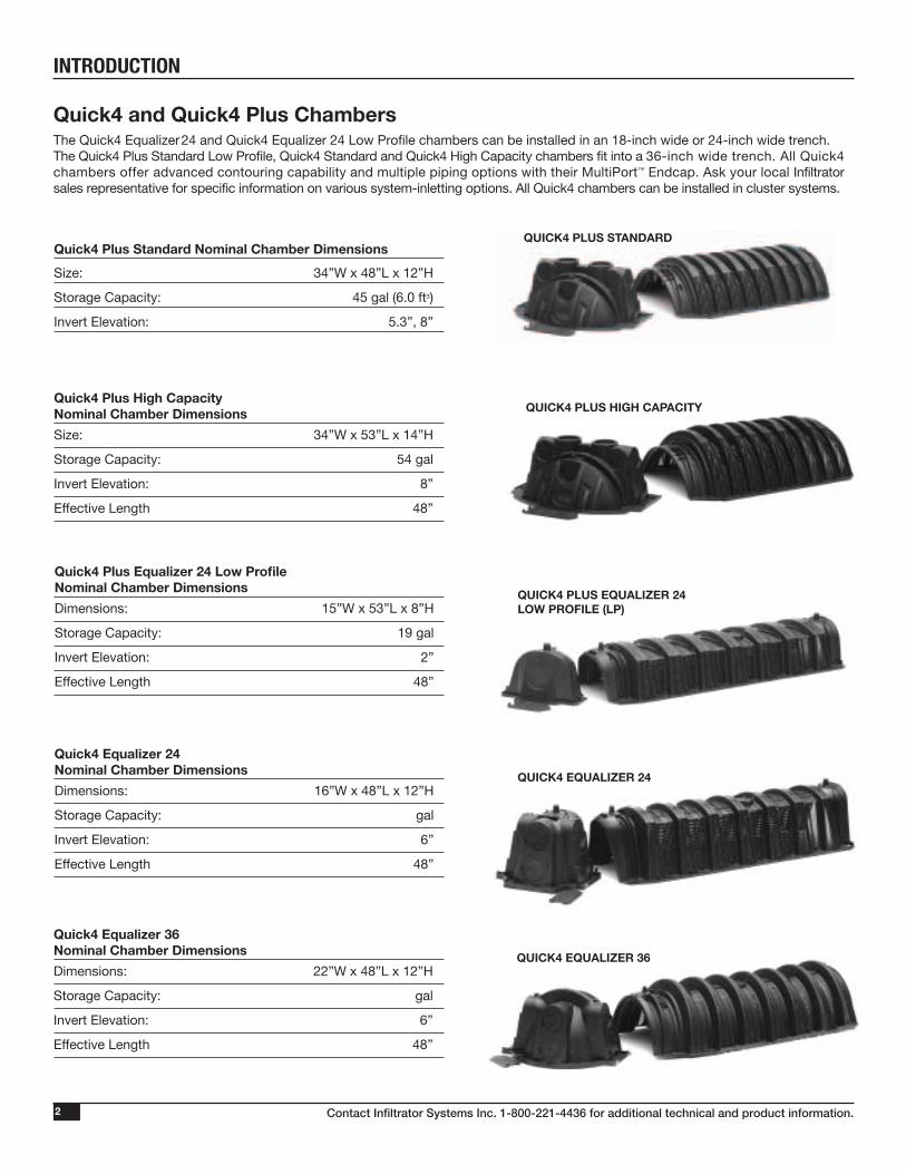
Quick4 and Quick4 Plus ChambersThe Quick4 Equalizer 24 and Quick4 Equalizer 24 Low Profile chambers can be installed in an 18-inch wide or 24-inch wide trench. The Quick4 Plus Standard Low Profile, Quick4 Standard and Quick4 High Capacity chambers fit into a 36-inch wide trench. All Quick4 chambers offer advanced contouring capability and multiple piping options with their MultiPort™ Endcap. Ask your local Infiltrator sales representative for specific information on various system-inletting options. All Quick4 chambers can be installed in cluster systems.
QUICK4 PLUS HIGH CAPACITYQuick4 Plus High Capacity Nominal Chamber Dimensions
Size: 34”W x 53”L x 14”H
Storage Capacity: 54 gal
Invert Elevation: 8”
Effective Length 48”
QUICK4 PLUS EQUALIZER 24LOW PROFILE (LP)
Quick4 Plus Equalizer 24 Low Profile Nominal Chamber Dimensions
Dimensions: 15”W x 53”L x 8”H
Storage Capacity: 19 gal
Invert Elevation: 2”
Effective Length 48”
QUICK4 EQUALIZER 24
QUICK4 EQUALIZER 36
Quick4 Equalizer 24 Nominal Chamber Dimensions
Dimensions: 16”W x 48”L x 12”H
Storage Capacity: gal
Invert Elevation: 6”
Effective Length 48”
Quick4 Equalizer 36 Nominal Chamber Dimensions
Dimensions: 22”W x 48”L x 12”H
Storage Capacity: gal
Invert Elevation: 6”
Effective Length 48”
QUICK4 PLUS STANDARDQuick4 Plus Standard Nominal Chamber Dimensions
Size: 34”W x 48”L x 12”H
Storage Capacity: 45 gal (6.0 ft3)
Invert Elevation: 5.3”, 8”
Contact Infiltrator Systems Inc. 1-800-221-4436 for additional technical and product information. 3
INTRODUCTION
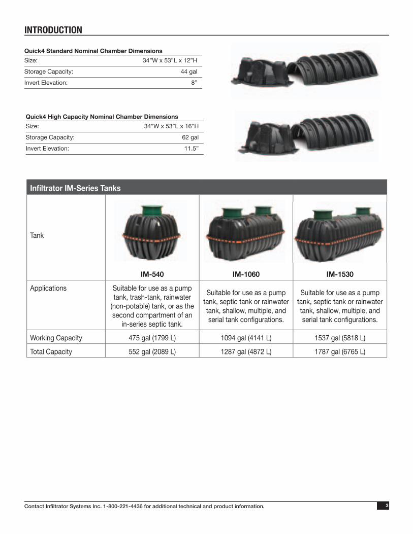
Quick4 Standard Nominal Chamber Dimensions
Size: 34”W x 53”L x 12”H
Storage Capacity: 44 gal
Invert Elevation: 8”
Quick4 High Capacity Nominal Chamber Dimensions
Size: 34”W x 53”L x 16”H
Storage Capacity: 62 gal
Invert Elevation: 11.5”
Infi ltrator IM-Series Tanks
Tank
IM-540 IM-1060 IM-1530
Applications Suitable for use as a pump tank, trash-tank, rainwater
(non-potable) tank, or as the second compartment of an
in-series septic tank.
Suitable for use as a pump tank, septic tank or rainwater tank, shallow, multiple, and serial tank confi gurations.
Suitable for use as a pump tank, septic tank or rainwater tank, shallow, multiple, and serial tank confi gurations.
Working Capacity 475 gal (1799 L) 1094 gal (4141 L) 1537 gal (5818 L)
Total Capacity 552 gal (2089 L) 1287 gal (4872 L) 1787 gal (6765 L)
Contact Infiltrator Systems Inc. 1-800-221-4436 for additional technical and product information.4
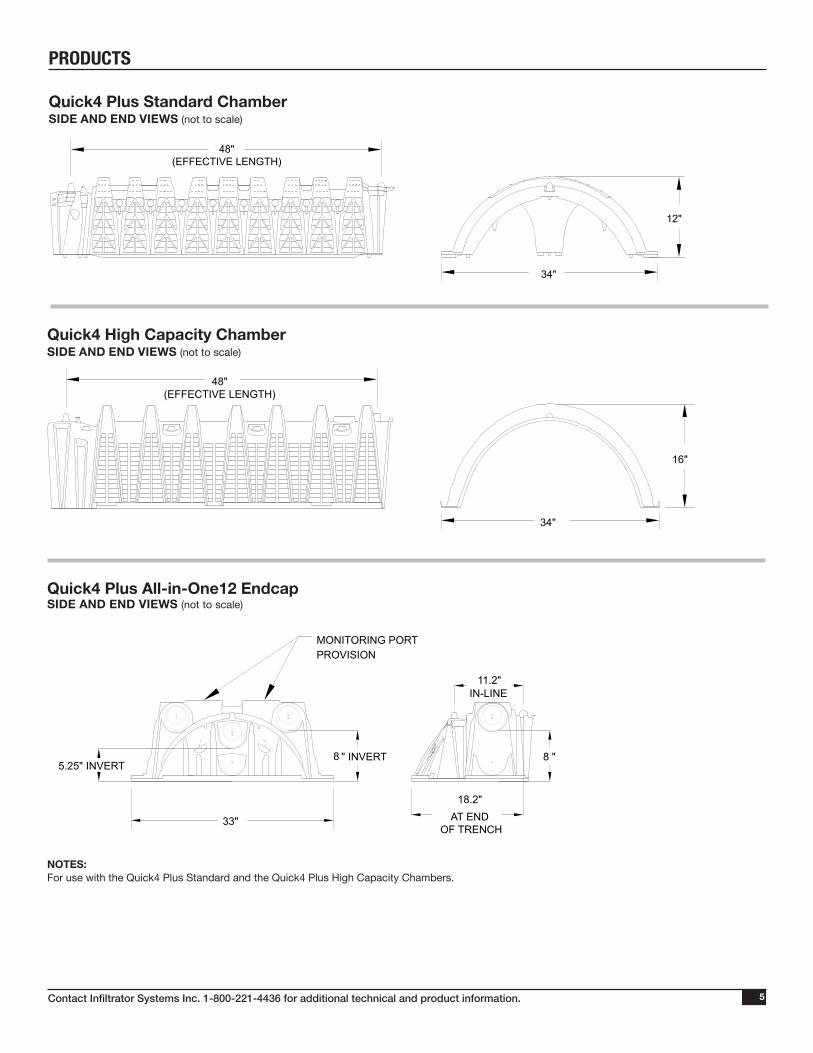
PRODUCTS
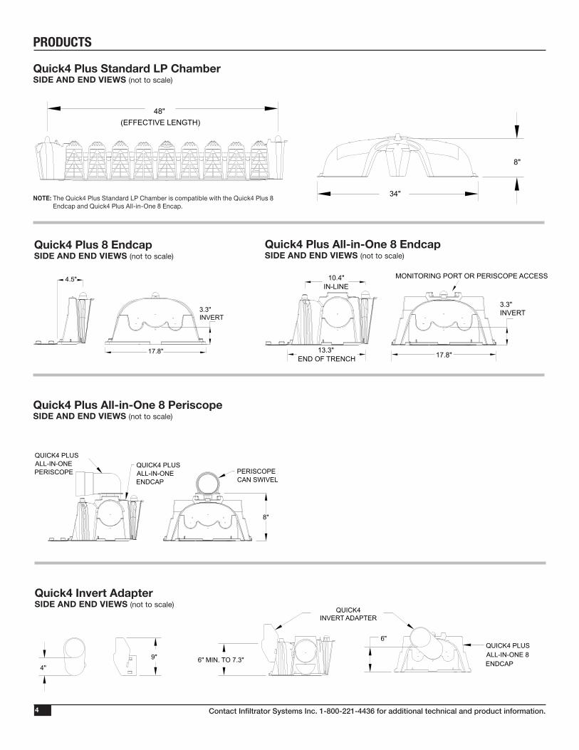
Quick4 Plus Standard LP ChamberSIDE AND END VIEWS (not to scale)
NOTE: The Quick4 Plus Standard LP Chamber is compatible with the Quick4 Plus 8 Endcap and Quick4 Plus All-in-One 8 Encap.
8"
48"(EFFECTIVE LENGTH)
34"
8"
48"(EFFECTIVE LENGTH)
34"
Quick4 Plus 8 EndcapSIDE AND END VIEWS (not to scale)
Quick4 Plus All-in-One 8 EndcapSIDE AND END VIEWS (not to scale)
Quick4 Invert AdapterSIDE AND END VIEWS (not to scale)
Quick4 Plus All-in-One 8 PeriscopeSIDE AND END VIEWS (not to scale)
13.3"END OF TRENCH
10.4"IN-LINE
17.8"
MONITORING PORT OR PERISCOPE ACCESS
3.3"INVERT
QUICK4 PLUSALL-IN-ONE 8ENDCAP
6"
6" MIN. TO 7.3"
QUICK4INVERT ADAPTER
4"9"
QUICK4 PLUSALL-IN-ONE 8ENDCAP
6"
6" MIN. TO 7.3"
QUICK4INVERT ADAPTER
4"9"
QUICK4 PLUS ALL-IN-ONE
PERISCOPE
PERISCOPECAN SWIVEL
8"
QUICK4 PLUSALL-IN-ONEPERISCOPE
QUICK4 PLUSALL-IN-ONEENDCAP
4.5"
3.3"INVERT
17.8"
Contact Infiltrator Systems Inc. 1-800-221-4436 for additional technical and product information. 5
Quick4 Plus Standard Chamber SIDE AND END VIEWS (not to scale)
PRODUCTS
12"
48"(EFFECTIVE LENGTH)
34"
33"*18"
13"
8" INVERT11.2"
*EFFECTIVE LENGTHWHEN CONNECTED*
12"
48"(EFFECTIVE LENGTH)
34"
33"*18"
13"
8" INVERT11.2"
*EFFECTIVE LENGTHWHEN CONNECTED*
Quick4 High Capacity Chamber SIDE AND END VIEWS (not to scale)
16"
48"(EFFECTIVE LENGTH)
34"
16"
34"
*11.75"OUTLET
11.5" INVERT
*17"INLET
*EFFECTIVE LENGTHWHEN CONNECTED*
16"
48"(EFFECTIVE LENGTH)
34"
16"
34"
*11.75"OUTLET
11.5" INVERT
*17"INLET
*EFFECTIVE LENGTHWHEN CONNECTED*
Quick4 Plus All-in-One12 EndcapSIDE AND END VIEWS (not to scale)
MONITORING PORTPROVISION
33"
5.25" INVERT8 " INVERT
18.2"AT END
OF TRENCH
8 "
11.2"IN-LINE
NOTES:For use with the Quick4 Plus Standard and the Quick4 Plus High Capacity Chambers.
Contact Infiltrator Systems Inc. 1-800-221-4436 for additional technical and product information.6
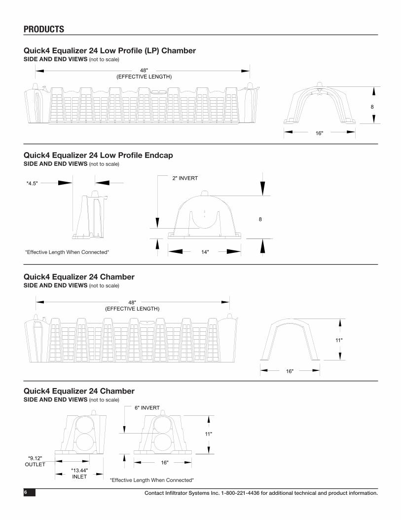
Quick4 Equalizer 24 Low Profile (LP) ChamberSIDE AND END VIEWS (not to scale)
Quick4 Equalizer 24 Low Profile EndcapSIDE AND END VIEWS (not to scale)
Quick4 Equalizer 24 ChamberSIDE AND END VIEWS (not to scale)
Quick4 Equalizer 24 ChamberSIDE AND END VIEWS (not to scale)
PRODUCTS
8
48"(EFFECTIVE LENGTH)
16"
14"
8
*4.5"2" INVERT
*EFFECTIVE LENGTH
WHEN CONNECTED*
8
48"(EFFECTIVE LENGTH)
16"
14"
8
*4.5"2" INVERT
*EFFECTIVE LENGTH
WHEN CONNECTED*
*Effective Length When Connected*
*Effective Length When Connected*
11"
48"(EFFECTIVE LENGTH)
16"
16"*13.44"INLET
11"
*9.12"OUTLET
6" INVERT
*EFFECTIVE LENGTH
WHEN CONNECTED*
11"
48"(EFFECTIVE LENGTH)
16"
16"*13.44"INLET
11"
*9.12"OUTLET
6" INVERT
*EFFECTIVE LENGTH
WHEN CONNECTED*
Contact Infiltrator Systems Inc. 1-800-221-4436 for additional technical and product information. 7
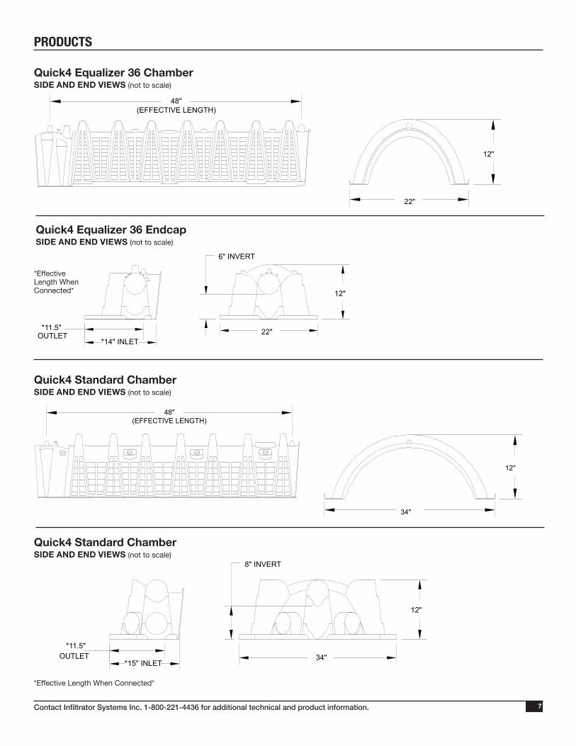
Quick4 Equalizer 36 ChamberSIDE AND END VIEWS (not to scale)
Quick4 Equalizer 36 EndcapSIDE AND END VIEWS (not to scale)
Quick4 Standard ChamberSIDE AND END VIEWS (not to scale)
Quick4 Standard ChamberSIDE AND END VIEWS (not to scale)
PRODUCTS
*Effective Length When Connected*
*Effective Length When Connected*
12"
48"(EFFECTIVE LENGTH)
22"
22"
12"
*11.5"OUTLET
6" INVERT
*14" INLET
*EFFECTIVE LENGTHWHEN CONNECTED*
12"
48"(EFFECTIVE LENGTH)
22"
22"
12"
*11.5"OUTLET
6" INVERT
*14" INLET
*EFFECTIVE LENGTHWHEN CONNECTED*48"
(EFFECTIVE LENGTH)
12"
34"
*EFFECTIVE LENGTH WHEN CONNECTED*
*11.5" OUTLET 34"
12"
*15" INLET
8" INVERT
48"(EFFECTIVE LENGTH)
12"
34"
*EFFECTIVE LENGTH WHEN CONNECTED*
*11.5" OUTLET 34"
12"
*15" INLET
8" INVERT
Contact Infiltrator Systems Inc. 1-800-221-4436 for additional technical and product information.8
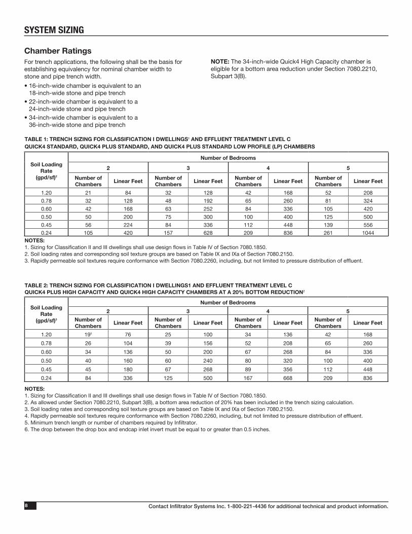
SYSTEM SIZING
Chamber Ratings For trench applications, the following shall be the basis for establishing equivalency for nominal chamber width to stone and pipe trench width.
• 16-inch-wide chamber is equivalent to an 18-inch-wide stone and pipe trench
• 22-inch-wide chamber is equivalent to a 24-inch-wide stone and pipe trench
• 34-inch-wide chamber is equivalent to a 36-inch-wide stone and pipe trench
NOTE: The 34-inch-wide Quick4 High Capacity chamber is eligible for a bottom area reduction under Section 7080.2210, Subpart 3(B).
TABLE 1: TRENCH SIZING FOR CLASSIFICATION I DWELLINGS1 AND EFFLUENT TREATMENT LEVEL CQUICK4 STANDARD, QUICK4 PLUS STANDARD, AND QUICK4 PLUS STANDARD LOW PROFILE (LP) CHAMBERS
Soil Loading Rate
(gpd/sf)2
Number of Bedrooms
2 3 4 5
Number of Chambers
Linear FeetNumber of Chambers
Linear FeetNumber of Chambers
Linear FeetNumber of Chambers
Linear Feet
1.20 21 84 32 128 42 168 52 208
0.78 32 128 48 192 65 260 81 324
0.60 42 168 63 252 84 336 105 420
0.50 50 200 75 300 100 400 125 500
0.45 56 224 84 336 112 448 139 556
0.24 105 420 157 628 209 836 261 1044NOTES:1. Sizing for Classification II and III dwellings shall use design flows in Table IV of Section 7080.1850.2. Soil loading rates and corresponding soil texture groups are based on Table IX and IXa of Section 7080.2150. 3. Rapidly permeable soil textures require conformance with Section 7080.2260, including, but not limited to pressure distribution of effluent.
TABLE 2: TRENCH SIZING FOR CLASSIFICATION I DWELLINGS1 AND EFFLUENT TREATMENT LEVEL C QUICK4 PLUS HIGH CAPACITY AND QUICK4 HIGH CAPACITY CHAMBERS AT A 20% BOTTOM REDUCTION2
Soil Loading Rate
(gpd/sf)3
Number of Bedrooms
2 3 4 5
Number of Chambers
Linear FeetNumber of Chambers
Linear FeetNumber of Chambers
Linear FeetNumber of Chambers
Linear Feet
1.20 195 76 25 100 34 136 42 168
0.78 26 104 39 156 52 208 65 260
0.60 34 136 50 200 67 268 84 336
0.50 40 160 60 240 80 320 100 400
0.45 45 180 67 268 89 356 112 448
0.24 84 336 125 500 167 668 209 836
NOTES:1. Sizing for Classification II and III dwellings shall use design flows in Table IV of Section 7080.1850.2. As allowed under Section 7080.2210, Subpart 3(B), a bottom area reduction of 20% has been included in the trench sizing calculation.3. Soil loading rates and corresponding soil texture groups are based on Table IX and IXa of Section 7080.2150.4. Rapidly permeable soil textures require conformance with Section 7080.2260, including, but not limited to pressure distribution of effluent.5. Minimum trench length or number of chambers required by Infiltrator.6. The drop between the drop box and endcap inlet invert must be equal to or greater than 0.5 inches.
Contact Infiltrator Systems Inc. 1-800-221-4436 for additional technical and product information. 9
SYSTEM SIZING
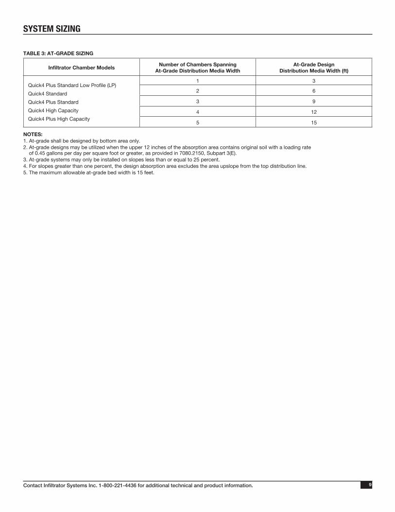
TABLE 3: AT-GRADE SIZING
Infiltrator Chamber ModelsNumber of Chambers Spanning
At-Grade Distribution Media WidthAt-Grade Design
Distribution Media Width (ft)
Quick4 Plus Standard Low Profile (LP)
Quick4 Standard
Quick4 Plus Standard
Quick4 High Capacity
Quick4 Plus High Capacity
1 3
2 6
3 9
4 12
5 15
NOTES:1. At-grade shall be designed by bottom area only.2. At-grade designs may be utilized when the upper 12 inches of the absorption area contains original soil with a loading rate
of 0.45 gallons per day per square foot or greater, as provided in 7080.2150, Subpart 3(E).3. At-grade systems may only be installed on slopes less than or equal to 25 percent.4. For slopes greater than one percent, the design absorption area excludes the area upslope from the top distribution line.5. The maximum allowable at-grade bed width is 15 feet.
Contact Infiltrator Systems Inc. 1-800-221-4436 for additional technical and product information.10
SYSTEM SIZING
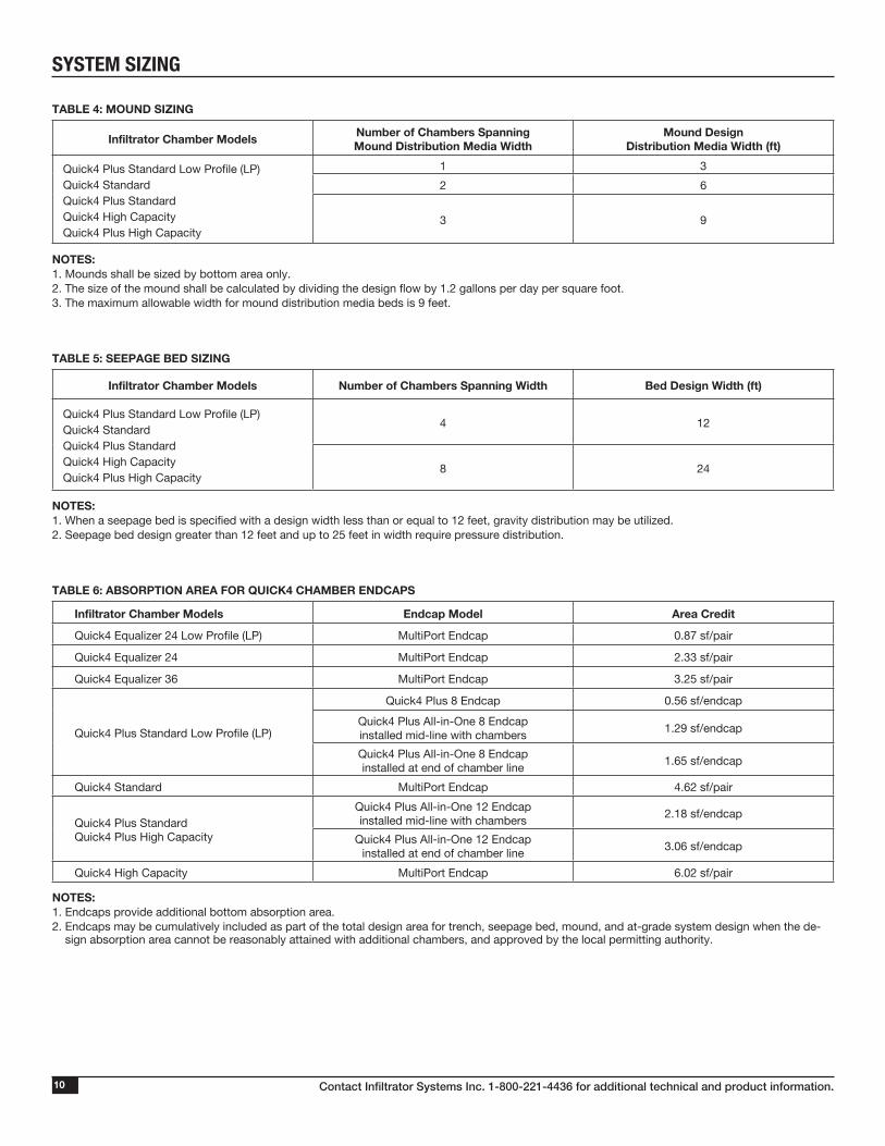
TABLE 4: MOUND SIZING
Infiltrator Chamber ModelsNumber of Chambers Spanning Mound Distribution Media Width
Mound Design Distribution Media Width (ft)
Quick4 Plus Standard Low Profile (LP)Quick4 StandardQuick4 Plus StandardQuick4 High CapacityQuick4 Plus High Capacity
1 3
2 6
3 9
NOTES:1. Mounds shall be sized by bottom area only.2. The size of the mound shall be calculated by dividing the design flow by 1.2 gallons per day per square foot.3. The maximum allowable width for mound distribution media beds is 9 feet.
TABLE 5: SEEPAGE BED SIZING
Infiltrator Chamber Models Number of Chambers Spanning Width Bed Design Width (ft)
Quick4 Plus Standard Low Profile (LP)Quick4 StandardQuick4 Plus StandardQuick4 High CapacityQuick4 Plus High Capacity
4 12
8 24
NOTES:1. When a seepage bed is specified with a design width less than or equal to 12 feet, gravity distribution may be utilized.2. Seepage bed design greater than 12 feet and up to 25 feet in width require pressure distribution.
TABLE 6: ABSORPTION AREA FOR QUICK4 CHAMBER ENDCAPS
Infiltrator Chamber Models Endcap Model Area Credit
Quick4 Equalizer 24 Low Profile (LP) MultiPort Endcap 0.87 sf/pair
Quick4 Equalizer 24 MultiPort Endcap 2.33 sf/pair
Quick4 Equalizer 36 MultiPort Endcap 3.25 sf/pair
Quick4 Plus Standard Low Profile (LP)
Quick4 Plus 8 Endcap 0.56 sf/endcap
Quick4 Plus All-in-One 8 Endcap installed mid-line with chambers
1.29 sf/endcap
Quick4 Plus All-in-One 8 Endcap installed at end of chamber line
1.65 sf/endcap
Quick4 Standard MultiPort Endcap 4.62 sf/pair
Quick4 Plus StandardQuick4 Plus High Capacity
Quick4 Plus All-in-One 12 Endcap installed mid-line with chambers
2.18 sf/endcap
Quick4 Plus All-in-One 12 Endcap installed at end of chamber line
3.06 sf/endcap
Quick4 High Capacity MultiPort Endcap 6.02 sf/pair
NOTES:1. Endcaps provide additional bottom absorption area.2. Endcaps may be cumulatively included as part of the total design area for trench, seepage bed, mound, and at-grade system design when the de-
sign absorption area cannot be reasonably attained with additional chambers, and approved by the local permitting authority.
Contact Infiltrator Systems Inc. 1-800-221-4436 for additional technical and product information. 11
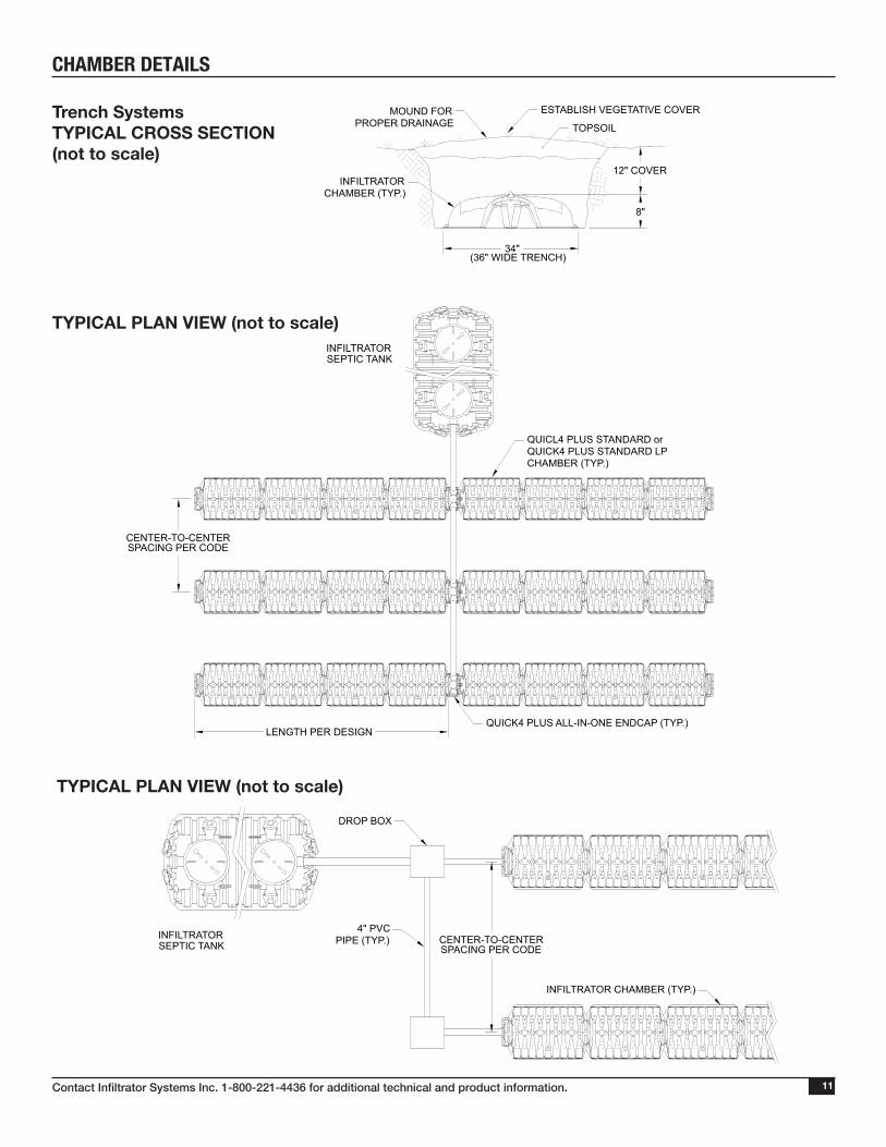
CHAMBER DETAILS
TYPICAL PLAN VIEW (not to scale)
TYPICAL PLAN VIEW (not to scale)
(36" WIDE TRENCH)
12" COVER
8"
34"
TOPSOIL
ESTABLISH VEGETATIVE COVERMOUND FORPROPER DRAINAGE
INFILTRATORCHAMBER (TYP.)
QUICL4 PLUS STANDARD orQUICK4 PLUS STANDARD LPCHAMBER (TYP.)
CENTER-TO-CENTERSPACING PER CODE
LENGTH PER DESIGNQUICK4 PLUS ALL-IN-ONE ENDCAP (TYP.)
INFILTRATORSEPTIC TANK
DROP BOX
INFILTRATORSEPTIC TANK CENTER-TO-CENTER
SPACING PER CODE
4" PVCPIPE (TYP.)
INFILTRATOR CHAMBER (TYP.)
Trench SystemsTYPICAL CROSS SECTION(not to scale)
Contact Infiltrator Systems Inc. 1-800-221-4436 for additional technical and product information.12
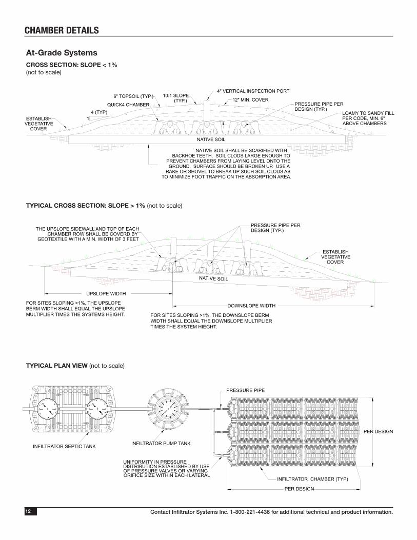
CHAMBER DETAILS
At-Grade SystemsCROSS SECTION: SLOPE < 1% (not to scale)
TYPICAL PLAN VIEW (not to scale)
NATIVE SOIL
PRESSURE PIPE PERDESIGN (TYP.)THE UPSLOPE SIDEWALL AND TOP OF EACH
CHAMBER ROW SHALL BE COVERD BYGEOTEXTILE WITH A MIN. WIDTH OF 3 FEET
ESTABLISHVEGETATIVE
COVER
UPSLOPE WIDTH
DOWNSLOPE WIDTHFOR SITES SLOPING >1%, THE UPSLOPE BERM WIDTH SHALL EQUAL THE UPSLOPE MULTIPLIER TIMES THE SYSTEMS HEIGHT. FOR SITES SLOPING >1%, THE DOWNSLOPE BERM
WIDTH SHALL EQUAL THE DOWNSLOPE MULTIPLIER TIMES THE SYSTEM HIEGHT.
4 (TYP)1
NATIVE SOIL
NATIVE SOIL SHALL BE SCARIFIED WITH BACKHOE TEETH. SOIL CLODS LARGE ENOUGH TO
PREVENT CHAMBERS FROM LAYING LEVEL ONTO THE GROUND. SURFACE SHOULD BE BROKEN UP. USE A
RAKE OR SHOVEL TO BREAK UP SUCH SOIL CLODS AS TO MINIMIZE FOOT TRAFFIC ON THE ABSORPTION AREA.
PRESSURE PIPE PERDESIGN (TYP.)
10:1 SLOPE(TYP.)
4" VERTICAL INSPECTION PORT
12" MIN. COVER6" TOPSOIL (TYP.)
ESTABLISHVEGETATIVE
COVER
LOAMY TO SANDY FILLPER CODE, MIN. 6"ABOVE CHAMBERS
QUICK4 CHAMBER
TYPICAL CROSS SECTION: SLOPE > 1% (not to scale)
INFILTRATOR SEPTIC TANK
PRESSURE PIPE
INFILTRATOR CHAMBER (TYP)
INFILTRATOR PUMP TANK
PER DESIGN
PER DESIGN
UNIFORMITY IN PRESSUREDISTRIBUTION ESTABLISHED BY USEOF PRESSURE VALVES OR VARYINGORIFICE SIZE WITHIN EACH LATERAL
Contact Infiltrator Systems Inc. 1-800-221-4436 for additional technical and product information. 13
CHAMBER DETAILS
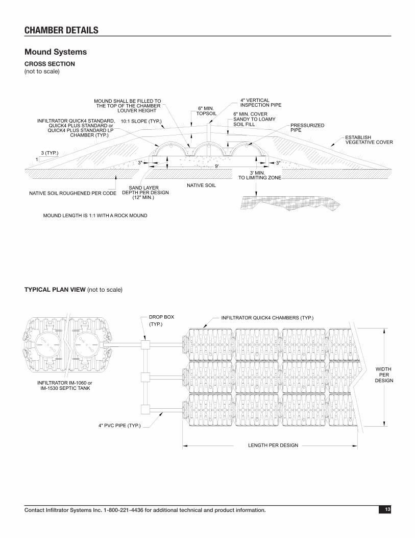
Mound SystemsCROSS SECTION (not to scale)
TYPICAL PLAN VIEW (not to scale)
NATIVE SOIL
1
SAND LAYERDEPTH PER DESIGN
(12" MIN.)
3' MIN.TO LIMITING ZONE
NATIVE SOIL ROUGHENED PER CODE
6" MIN. COVERSANDY TO LOAMY SOIL FILL
6" MIN. TOPSOIL
MOUND LENGTH IS 1:1 WITH A ROCK MOUND
3"3"9'
INFILTRATOR QUICK4 STANDARD,QUICK4 PLUS STANDARD orQUICK4 PLUS STANDARD LP
CHAMBER (TYP.) ESTABLISHVEGETATIVE COVER
PRESSURIZEDPIPE
MOUND SHALL BE FILLED TOTHE TOP OF THE CHAMBER
LOUVER HEIGHT
10:1 SLOPE (TYP.)
3 (TYP.)
4" VERTICALINSPECTION PIPE
LENGTH PER DESIGN
4" PVC PIPE (TYP.)
INFILTRATOR IM-1060 orIM-1530 SEPTIC TANK
WIDTH PER
DESIGN
INFILTRATOR QUICK4 CHAMBERS (TYP.)DROP BOX(TYP.)
Contact Infiltrator Systems Inc. 1-800-221-4436 for additional technical and product information.14
CHAMBER DETAILS
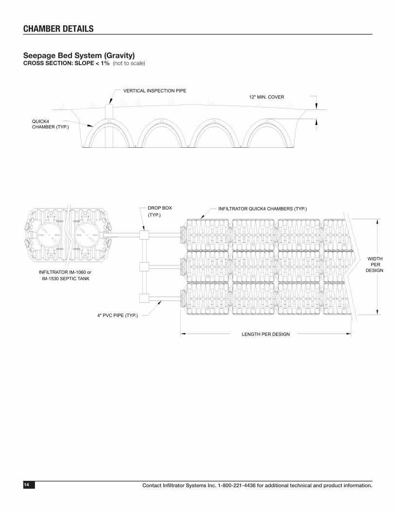
Seepage Bed System (Gravity)CROSS SECTION: SLOPE < 1% (not to scale)
QUICK4CHAMBER (TYP.)
VERTICAL INSPECTION PIPE12" MIN. COVER
LENGTH PER DESIGN
4" PVC PIPE (TYP.)
INFILTRATOR IM-1060 orIM-1530 SEPTIC TANK
WIDTHPER
DESIGN
INFILTRATOR QUICK4 CHAMBERS (TYP.)DROP BOX(TYP.)
Contact Infiltrator Systems Inc. 1-800-221-4436 for additional technical and product information. 15
Before You BeginQuick4 Chambers may only be installed according to State and/or local regulations. If unsure of the installation requirements for a particular site, contact the local unit of government.
All systems require a design, which includes a thorough site and soil evaluation of system sizing and the issuance of a local permit to construct the system. The system installer must schedule required regulatory inspections.
Excavating and Preparing the SiteNOTE: As is the case with conventional systems, do not install the systems in wet conditions or in overly moist soils, as this causes machinery to smear the soil.1. Stake out the location of all chamber lines. Set the elevations of the tank, pipe, and system bottom.2. Install sedimentation and erosion control measures. Temporary drainage swales/berms may be installed to protect the site during rainfall events.3. Excavate and level the trenches with proper center-to-center sep aration. Verify that the bottom of the system is level and that it is at least 3 feet abov e the limiting layer.NOTE: Over excavate the trench width in areas where the cham-ber line will contour. 4. Rake the bottom and sides if smearing has occurred while excavating. Remove any large stones and other debris. Do not use the bucket teeth to rake the trench bottom. Minimize or avoid walking in the trench to prevent compaction, loss of soil structure, and the subsequent reduction in the soil’s infiltrative capacity.NOTE: Raking to eliminate smearing is not necessary in sandy soils. In fine textured soils (silts and clays), avoid walking in the trench to prevent compaction and loss of soil structure.5. Verify that the bottom of the system is level using a level, transit, or laser.
Materials and Equipment Needed Quick4 chambers Utility Knife
Endcaps Hole Saw*
PVC pipe and couplings 2-inch Drywall Screws*
Backhoe Screw gun*
Laser, transit or level Small valve-cover box*
Shovel and rake 4-inch cap for Inspection port
Tape Measure *Optional
These guidelines for construction machinery must be followed during installation.
Avoid direct contact with chambers when using construction equipment. Chambers require a 12-inch minimum of compacted cover to support a wheel load rating of 16,000 lbs/axle or equivalent to an H-10 AASHTO load rating.
Only drive across the trenches when necessary. Never drive down the length of the trenches.
To avoid additional soil compaction, never drive heavy vehicles over the completed system.
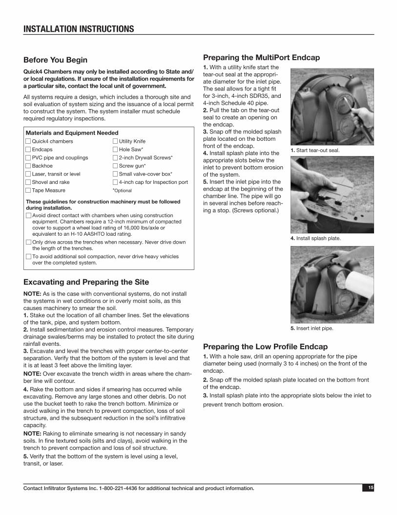
Preparing the MultiPort Endcap1. With a utility knife start the tear-out seal at the appropri-ate diameter for the inlet pipe. The seal allows for a tight fit for 3-inch, 4-inch SDR35, and 4-inch Schedule 40 pipe.2. Pull the tab on the tear-out seal to create an opening on the endcap.3. Snap off the molded splash plate located on the bottom front of the endcap.4. Install splash plate into the appropriate slots below the inlet to prevent bottom erosion of the system.5. Insert the inlet pipe into the endcap at the beginning of the chamber line. The pipe will go in several inches before reach-ing a stop. (Screws optional.)
Preparing the Low Profile Endcap1. With a hole saw, drill an opening appropriate for the pipe diameter being used (normally 3 to 4 inches) on the front of the endcap.
2. Snap off the molded splash plate located on the bottom front of the endcap. 3. Install splash plate into the appropriate slots below the inlet to
prevent trench bottom erosion.
1. Start tear-out seal.
4. Install splash plate.
5. Insert inlet pipe.
INSTALLATION INSTRUCTIONS
Contact Infiltrator Systems Inc. 1-800-221-4436 for additional technical and product information.16
6. Attach endcap to chamber.
4. Lock chambers together.
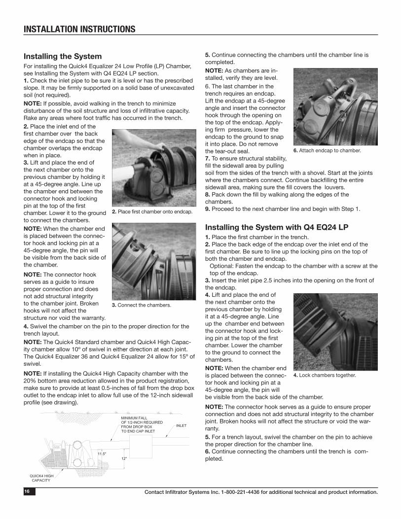
Installing the SystemFor installing the Quick4 Equalizer 24 Low Profile (LP) Chamber, see Installing the System with Q4 EQ24 LP section.1. Check the inlet pipe to be sure it is level or has the prescribed slope. It may be firmly supported on a solid base of unexcavated soil (not required).NOTE: If possible, avoid walking in the trench to minimize disturbance of the soil structure and loss of infiltrative capacity. Rake any areas where foot traffic has occurred in the trench.2. Place the inlet end of the first chamber over the back edge of the endcap so that the chamber overlaps the endcap when in place.3. Lift and place the end of the next chamber onto the previous chamber by holding it at a 45-degree angle. Line up the chamber end between the connector hook and locking pin at the top of the first chamber. Lower it to the ground to connect the chambers. NOTE: When the chamber end is placed between the connec-tor hook and locking pin at a 45-degree angle, the pin will be visible from the back side of the chamber.
NOTE: The connector hook serves as a guide to insure proper connection and does not add structural integrity to the chamber joint. Broken hooks will not affect the structure nor void the warranty. 4. Swivel the chamber on the pin to the proper direction for the trench layout.NOTE: The Quick4 Standard chamber and Quick4 High Capac-ity chamber allow 10º of swivel in either direction at each joint. The Quick4 Equalizer 36 and Quick4 Equalizer 24 allow for 15º of swivel.
NOTE: If installing the Quick4 High Capacity chamber with the 20% bottom area reduction allowed in the product registration, make sure to provide at least 0.5-inches of fall from the drop box outlet to the endcap inlet to allow full use of the 12-inch sidewall profile (see drawing).
3. Connect the chambers.
2. Place first chamber onto endcap.
5. Continue connecting the chambers until the chamber line is completed. NOTE: As chambers are in-stalled, verify they are level.6. The last chamber in the trench requires an endcap. Lift the endcap at a 45-degree angle and insert the connector hook through the opening on the top of the endcap. Apply-ing firm pressure, lower the endcap to the ground to snap it into place. Do not remove the tear-out seal. 7. To ensure structural stability, fill the sidewall area by pulling soil from the sides of the trench with a shovel. Start at the joints where the chambers connect. Continue backfilling the entire sidewall area, making sure the fill covers the louvers.8. Pack down the fill by walking along the edges of the chambers. 9. Proceed to the next chamber line and begin with Step 1.
Installing the System with Q4 EQ24 LP1. Place the first chamber in the trench.2. Place the back edge of the endcap over the inlet end of the first chamber. Be sure to line up the locking pins on the top of both the chamber and endcap. Optional: Fasten the endcap to the chamber with a screw at the
top of the endcap.3. Insert the inlet pipe 2.5 inches into the opening on the front of the endcap. 4. Lift and place the end of the next chamber onto the previous chamber by holding it at a 45-degree angle. Line up the chamber end between the connector hook and lock-ing pin at the top of the first chamber. Lower the chamber to the ground to connect the chambers.NOTE: When the chamber end is placed between the connec-tor hook and locking pin at a 45-degree angle, the pin will be visible from the back side of the chamber.
NOTE: The connector hook serves as a guide to ensure proper connection and does not add structural integrity to the chamber joint. Broken hooks will not affect the structure or void the war-ranty.5. For a trench layout, swivel the chamber on the pin to achieve the proper direction for the chamber line. 6. Continue connecting the chambers until the trench is com-pleted.
INSTALLATION INSTRUCTIONS
Contact Infiltrator Systems Inc. 1-800-221-4436 for additional technical and product information. 17
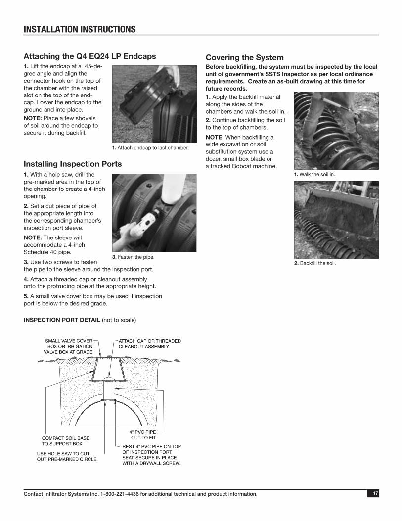
Attaching the Q4 EQ24 LP Endcaps1. Lift the endcap at a 45-de-gree angle and align the connector hook on the top of the chamber with the raised slot on the top of the end-cap. Lower the endcap to the ground and into place. NOTE: Place a few shovels of soil around the endcap to secure it during backfill.
Installing Inspection Ports1. With a hole saw, drill the pre-marked area in the top of the chamber to create a 4-inch opening.
2. Set a cut piece of pipe of the appropriate length into the corresponding chamber’s inspection port sleeve.
NOTE: The sleeve will accommodate a 4-inch Schedule 40 pipe.
3. Use two screws to fasten the pipe to the sleeve around the inspection port.
4. Attach a threaded cap or cleanout assembly onto the protruding pipe at the appropriate height.
5. A small valve cover box may be used if inspection port is below the desired grade.
INSPECTION PORT DETAIL (not to scale)
1. Attach endcap to last chamber.
3. Fasten the pipe.
SMALL VALVE COVERBOX OR IRRIGATION
VALVE BOX AT GRADE
COMPACT SOIL BASETO SUPPORT BOX
USE HOLE SAW TO CUTOUT PRE-MARKED CIRCLE.
ATTACH CAP OR THREADEDCLEANOUT ASSEMBLY.
4" PVC PIPECUT TO FIT
REST 4" PVC PIPE ON TOP OF INSPECTION PORT SEAT. SECURE IN PLACE WITH A DRYWALL SCREW.
Covering the SystemBefore backfilling, the system must be inspected by the local unit of government’s SSTS Inspector as per local ordinance requirements. Create an as-built drawing at this time for future records.1. Apply the backfill material along the sides of the chambers and walk the soil in.2. Continue backfilling the soil to the top of chambers.
NOTE: When backfilling a wide excavation or soil substitution system use a dozer, small box blade or a tracked Bobcat machine.
1. Walk the soil in.
2. Backfill the soil.
INSTALLATION INSTRUCTIONS
Contact Infiltrator Systems Inc. 1-800-221-4436 for additional technical and product information.18
INSTALLATION INSTRUCTIONS
Seepage Bed Systems
Before You Begin
This document provides septic installation instructions for Quick4 chambers in bed systems. These chambers may only be installed according to state and local regulations. If unsure of the installa-tion requirements, contact the local unit of government.
All systems require a design, which includes a thorough site and soil evaluation, system sizing, and the issuance of a local permit to construct the system.
TYPICAL BED SYSTEM PLAN VIEW (not to scale)
Excavating and Preparing the SiteNOTE: It is not recommended to install systems in wet conditions or in overly moist soils, as this causes machinery to smear the soil interface which can affect system performance.
1. Stake out the location of the bed and set the elevations of the tanks, pump chamber (if required), pre-treatment devices (if required), piping, and bed bottom. Install sedimentation and erosion control barriers as necessary.
2. Excavate and level the designated area. Be sure to excavate at least one extra foot around perimeter to allow for proper fit and ease installation.
Materials and Equipment Needed Quick4 chambers Utility Knife Endcaps Hole Saw / Router Bit* Backhoe / bulldozer D-Box* Laser, transit or level Tape Measure 4-inch PVC Pipe and Couplings *Optional
These guidelines for construction machinery must be followed during installation.
Avoid direct contact with chambers when using construction equipment. Chambers require a 12-inch minimum of compacted cover to support a wheel load rating of 16,000 lbs/axle or equivalent to an H-10 AASHTO load rating.
Only drive across the trenches when necessary. Never drive down the length of the trenches.
Prior to compaction and during backfill, only use tracked vehicles. Always keep 6 inches of soil between tracks and chambers.
3. If required, be sure to dig through any restrictive layer to the more suitable soils. Remove any debris from the bed walls. Prepare the chamber bed’s sub grade soil as outlined in the designer’s plans.
4. Rake the bottom and sides if smearing has occurred while excavating. Verify the bottom of the bed is level using a transit, laser or level. Minimize or avoid walking on the bottom of the bed to prevent compaction, loss of soil structure and the subsequent reduction in the soil’s infiltrative capacity.
5. If pressure distribution is required, refer to the “Pressure Pipe Design Options” instructions provided in the Mound Systems section.
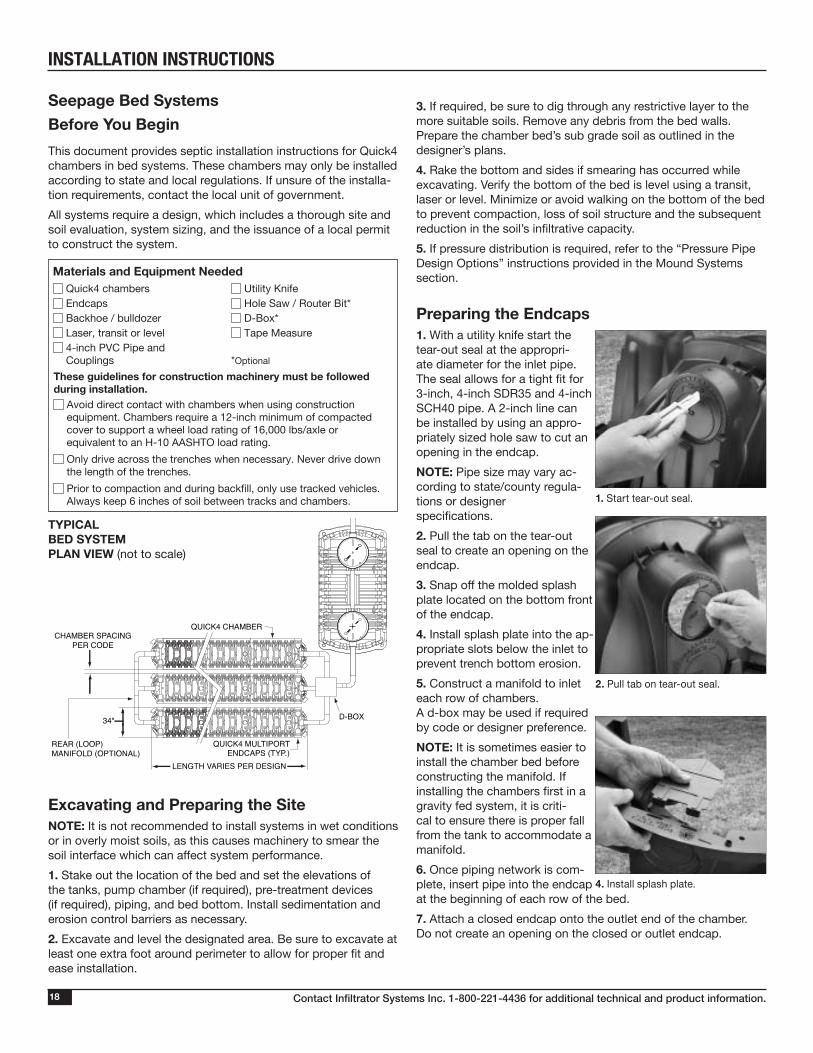
Preparing the Endcaps1. With a utility knife start the tear-out seal at the appropri-ate diameter for the inlet pipe. The seal allows for a tight fit for 3-inch, 4-inch SDR35 and 4-inch SCH40 pipe. A 2-inch line can be installed by using an appro-priately sized hole saw to cut an opening in the endcap.
NOTE: Pipe size may vary ac-cording to state/county regula-tions or designer specifications.
2. Pull the tab on the tear-out seal to create an opening on the endcap.
3. Snap off the molded splash plate located on the bottom front of the endcap.
4. Install splash plate into the ap-propriate slots below the inlet to prevent trench bottom erosion.
5. Construct a manifold to inlet each row of chambers. A d-box may be used if required by code or designer preference.
NOTE: It is sometimes easier to install the chamber bed before constructing the manifold. If installing the chambers first in a gravity fed system, it is criti-cal to ensure there is proper fall from the tank to accommodate a manifold.
6. Once piping network is com-plete, insert pipe into the endcap at the beginning of each row of the bed.
7. Attach a closed endcap onto the outlet end of the chamber. Do not create an opening on the closed or outlet endcap.
CHAMBER SPACINGPER CODE
QUICK4 CHAMBER
QUICK4 MULTIPORTENDCAPS (TYP.)
D-BOX
LENGTH VARIES PER DESIGN
34"
REAR (LOOP)MANIFOLD (OPTIONAL)
2. Pull tab on tear-out seal.
4. Install splash plate.
1. Start tear-out seal.
Contact Infiltrator Systems Inc. 1-800-221-4436 for additional technical and product information. 19
Installing the Bed System1. Construct the chamber bed by joining chambers. Place the inlet end of the first chamber over the back edge of the endcap.
2. Lift and place the end of the next chamber on to the previous chamber by holding it at a 90-degree angle. Line up the chamber end between the connector hook and lock-ing pin at the top of the first chamber. Lower to the ground to connect the chambers.
NOTE: When the chamber end is placed between the connec-tor hook and locking pin at a 90-degree angle, the pin will be visible from the back side of the chamber.
NOTE: The connector hook serves as a guide to ensure proper connection and does not add structural integrity to the chamber joint. Broken hooks will not affect the structure nor void the warranty.
3. Continue connecting the chambers until the first row is completed.
4. Check the first row of chambers to be sure that it is level.
5. Continue connecting chambers until the bed is complete. As the chambers are installed, verify that they are level, straight and maintain the required separation distance between each row of chambers.
NOTE: After installing chambers edge to edge or with up to 6” of spacing, it is important to properly backfill per current installation instructions so as to not compromise the integrity of the product.
6. The last chamber in the row requires an endcap. Lift the end-cap at a 45-degree angle and insert the connector hook through the opening on the top of the endcap. Applying firm pressure, lower the endcap to the ground to snap it into place. Do not remove the tear out seal if ends are not to be connected. Repeat this step for each row in the bed.
NOTE: Looping the outlet end of the bed may be required or specified by design. Infiltrator Systems recommends creating a hole in the endcap at the specified invert height.
7. Insert the loop manifold through the endcap and determine that the manifold is level before backfilling.
8. Bed systems require at least one vertical inspection pipe. Refer to the “Installing Inspection Ports” instructions provided in the Trench Systems section.
9. To ensure structural stability, fill the sidewall area by pulling soil in from the sides of the bed with a shovel or by placing fill material with a backhoe or excavator bucket.
10. Continue to carefully anchor chambers by ladling fill material between the chamber rows making sure not to dislodge the units. Be sure the fill extends above the louvers a minimum of two inches.
NOTE: Only drive over the system with a tracked v ehicle.
NOTE: Do not to drive over the chambers until a minimum of 12” of fill is placed above the chambers. For rows not accessible from the edge of the bed, wait until a majority of the chambers are covered with 6” of fill before stabilizing middle rows (for tracked vehicles only).
11. Pack down the fill by walking along the sidewalls of the chambers as this helps to give better structural support. In wet conditions, silty or clay soils, do not walk in the sidewalls.
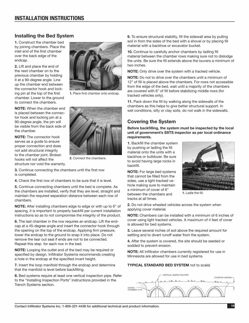
Covering the SystemBefore backfilling, the system must be inspected by the local unit of government’s SSTS inspector as per local ordinance requirements.
1. Backfill the chamber system by pushing or ladling the fill material onto the units with a backhoe or bulldozer. Be sure to avoid having large rocks in backfill.
NOTE: For large bed systems that cannot be filled from the sides, use a light tracked ve-hicle making sure to maintain a minimum of cover of 6” between the chambers and tracks at all times.
2. Do not drive wheeled vehicles across the system when applying cover material.
NOTE: Chambers can be installed with a minimum of 6 inches of cover using light tracked vehicles. A maximum of 4 feet of cover is allowed for bed systems.
3. Leave several inches of soil above the required amount for settling and to divert runoff water from the system.
4. After the system is covered, the site should be seeded or sodded to prevent erosion.
NOTE: All Infiltrator chambers currently registered for use in Minnesota are allowed for use in bed systems.
TYPICAL STANDARD BED SYSTEM not to scale)
1. Place first chamber onto endcap.
2. Connect the chambers.
1. Ladle the fill.
QUICK4 CHAMBER (TYP)
COVER BY DESIGN VERTICAL INSPECTION PIPE
INSTALLATION INSTRUCTIONS
Contact Infiltrator Systems Inc. 1-800-221-4436 for additional technical and product information.20
At-Grade Systems
Before You Begin
Quick4 chambers can only be installed according to state or county regulations. Contact your local unit of government for specific requirements.
Preparing the Site1. Review approved system design to determine the height of the seasonal high water table or other limiting factors.
2. Stake out the site for at-grade system placement.
3. Install sedimentation and erosion control measures.
4. Cut trees flush to the ground, remove surface boulders that can be easily rolled off, and remove vegetation per code requirements.
5. The original at-grade absorption area must be scarified by backhoe teeth, moldboard, or chisel plow.
Materials and Equipment Needed Quick4 chambers Utility Knife or Hole Saw*
Endcaps Glue
Pressure Lateral Pipe Rakeand Fittings
Plastic Pipe straps, all weather, Garden Hose*120 lb. tensile strength (nylon prohibited) Chisel Plow*
2” Drywall Screws* Paving Block* *Optional
These guidelines for construction machinery must be followed during installation.
Avoid direct contact with chambers when using construction equipment. Chambers require a 12-inch minimum of compacted cover to support a wheel load rating of 16,000 lbs/axle or equivalent to an H-10 AASHTO load rating.
Only drive across the trenches when necessary. Never drive down the length of the trenches.
Avoid stones larger than 3 inches in diameter in backfill. Remove stones this size or larger that are in contact with chambers.
Covering the SystemBefore backfilling, the system must be in spected by the local unit of government’s SSTS Inspector as per local ordinance requirements. System should be installed as per design.
1. For sites sloping greater than 1%, a geotextile fabric of at least 3-feet in width shall be placed over the upslope sidewall and chamber top to prevent intrusion of fill. A geotextile fabric spanning the width of the dispersal area and covering each chamber row may be used.
2. Place a 2-foot high pile of berm material around the perimeter of the at-grade and directly against the outer rows of chambers for stabilization.
3. Ladle clean sand between the chamber rows to the top sidewall louver to prevent chamber movement before final backfill. Firm the soil between the chamber rows by walking it in.
4. Push the berm material between and over the chamber rows with a tracked vehicle from the upslope side. Keep a minimum 12-inches of densified cover over the system.
NOTE: NO wheeled machinery is allowed on chambers in at-grades. Tracked vehicles may be used.
5. After the system is covered, the site shall be seeded or sodded per 7080.2150 Subp 3.J. to prevent erosion.
NOTE: If the system is for new home construction, it is important to place marking stakes along the boundary of the system. This will notify contractors of the site location so they will not cross it with equipment or vehicles.
INSTALLATION INSTRUCTIONS
Contact Infiltrator Systems Inc. 1-800-221-4436 for additional technical and product information. 21
Mound Systems
Before You Begin
Quick4 chambers can only be installed according to state or county regulations. Contact your local unit of government for specific requirements.
All systems require a design, which includes a thorough site and soil evaluation of system sizing and the issuance of a local permit to construct the system. The system installer must schedule required regulatory inspections.
Preparing the Site1. Review approved system design to determine the height of the seasonal high water table or other limiting factors.
2. Calculate the number of sand lifts necessary. Lifts should measure 6 to 12 inches in height.
3. Confirm that the sand used to build the mound meets Minnesota design standards. Sand must meet requirements of Chapter 7080.2220, subpart.3.(C).
4. Stake out the site for mound placement.
5. Install sedimentation and erosion control measures.
6. Cut trees flush to the ground, remove surface boulders that can be easily rolled off, and remove vegetation per code requirements.7. The original soil mound absorption area must be roughened by backhoe teeth, moldboard, or chisel plow. The soil must be roughened to a depth of eight inches.
Materials and Equipment Needed Quick4 chambers Utility Knife or Hole Saw*
Endcaps Glue
Pressure Lateral Pipe Rakeand Fittings
Plastic Pipe straps, all weather, Garden Hose*120 lb. tensile strength (nylon prohibited) Chisel Plow*
Sand and Specified Fill Material Paving Block*
Backhoe / Bulldozer / Skid-Steer *Optional
These guidelines for construction machinery must be followed during installation.
Avoid direct contact with chambers when using construction equipment. Chambers require a 12-inch minimum of compacted cover to support a wheel load rating of 16,000 lbs/axle or equivalent to an H-10 AASHTO load rating.
Only drive across the trenches when necessary. Never drive down the length of the trenches.
Avoid stones larger than 3 inches in diameter in backfill. Remove stones this size or larger that are in contact with chambers.
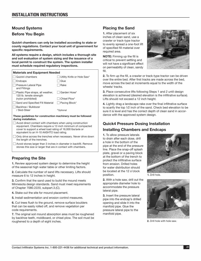
Placing the Sand1. After placement of six inches of clean sand, use a crawler or track-type tractor to evenly spread a one-foot lift of specified fill material over required area.
NOTE: Firming up the fill is critical to prevent settling and will not have a significant effect on permeability of clean, sandy fill.
2. To firm up the fill, a crawler or track-type tractor can be driven over the entire bed. After first tracks are made across the bed, move across the bed at increments equal to the width of the wheels/ tracks.
3. Place consecutive lifts following Steps 1 and 2 until design elevation is achieved (desired elevation is the infiltrative surface). Lifts should not exceed a 12 inch height.
4. Lightly drag a landscape rake over the final infiltrative surface to scarify the top 1⁄2 inch of the sand. Check bed elevation to be sure it is level and has the correct depth of clean sand in accor-dance with the approved system design.
Quick4 Pressure Dosing Installation
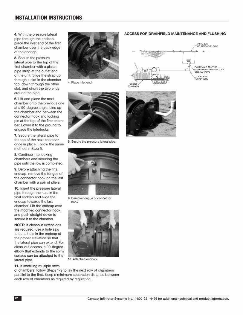
Installing Chambers and Endcaps1. To allow pressure laterals to drain after each dose, drill a hole in the bottom of the pipe at the end of the pressure line. Place the snap-off splash plate, gravel or a paving block at the bottom of the trench to protect the infiltrative surface from erosion. Drilled holes for water distribution should be located at the 12 o’clock position.
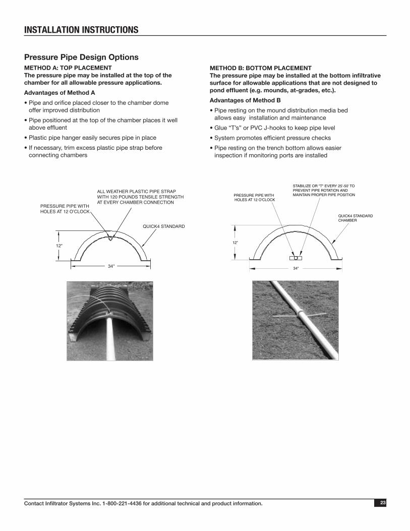
2. With a hole saw, drill out the appropriate diameter hole to accommodate the pressure lateral pipe.
3. Insert the pressure lateral pipe into the endcap’s drilled opening and slide it into the manifold pipe. Glue the pressure lateral pipe to the manifold pipe.
1. Drill hole.
2. Drill hole with hole saw.
INSTALLATION INSTRUCTIONS
Contact Infiltrator Systems Inc. 1-800-221-4436 for additional technical and product information.22
4. With the pressure lateral pipe through the endcap, place the inlet end of the first chamber over the back edge of the endcap.
5. Secure the pressure lateral pipe to the top of the first chamber with a plastic pipe strap at the outlet end of the unit. Slide the strap up through a slot in the chamber top, down through the other slot, and cinch the two ends around the pipe.
6. Lift and place the next chamber onto the previous one at a 90-degree angle. Line up the chamber end between the connector hook and locking pin at the top of the first cham-ber. Lower it to the ground to engage the interlocks.
7. Secure the lateral pipe to the top of the next chamber once in place. Follow the same method in Step 5.
8. Continue interlocking chambers and securing the pipe until the row is completed.
9. Before attaching the final endcap, remove the tongue of the connector hook on the last chamber with a pair of pliers.
10. Insert the pressure lateral pipe through the hole in the final endcap and slide the endcap towards the last chamber. Lift the endcap over the modified connector hook and push straight down to secure it to the chamber.
NOTE: If cleanout extensions are required, use a hole saw to cut a hole in the endcap at the proper elevation so that the lateral pipe can extend. For clean-out access, a 90-degree elbow that extends to the soil’s surface can be attached to the lateral pipe.
11. If installing multiple rows of chambers, follow Steps 1-9 to lay the next row of chambers parallel to the first. Keep a minimum separation distance between each row of chambers as required by regulation.
5. Secure the pressure lateral pipe.
4. Place inlet end.
9. Remove tongue of connector hook.
10. Attached endcap.
ACCESS FOR DRAINFIELD MAINTENANCE AND FLUSHING
INSTALLATION INSTRUCTIONS
Contact Infiltrator Systems Inc. 1-800-221-4436 for additional technical and product information. 23
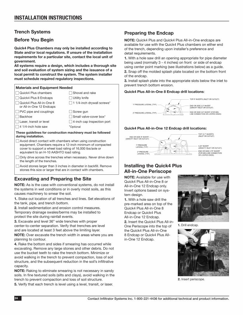
Pressure Pipe Design Options METHOD A: TOP PLACEMENT The pressure pipe may be installed at the top of the chamber for all allowable pressure applications.
Advantages of Method A
• Pipe and orifice placed closer to the chamber dome offer improved distribution
• Pipe positioned at the top of the chamber places it well above effluent
• Plastic pipe hanger easily secures pipe in place
• If necessary, trim excess plastic pipe strap before connecting chambers
METHOD B: BOTTOM PLACEMENT The pressure pipe may be installed at the bottom infiltrative surface for allowable applications that are not designed to pond effluent (e.g. mounds, at-grades, etc.).
Advantages of Method B
• Pipe resting on the mound distribution media bed allows easy installation and maintenance
• Glue “T’s” or PVC J-hooks to keep pipe level
• System promotes efficient pressure checks
• Pipe resting on the trench bottom allows easier inspection if monitoring ports are installed
6.5"
QUICK4 STANDARD
INSTALL A PIPE SUPPORT EVERY 10' TO PREVENT PIPE ROTATION AND MAINTAIN PROPER PIPE POSITION
PRESSURE PIPE WITH HOLES AT 12 O'CLOCK
QUICK4 STANDARD
PRESSURE PIPE WITHHOLES AT 12 O’CLOCK
ALL WEATHER PLASTIC PIPE STRAPWITH 120 POUNDS TENSILE STRENGTHAT EVERY CHAMBER CONNECTION
12"
34"
12"
34"
INSTALLATION INSTRUCTIONS
Contact Infiltrator Systems Inc. 1-800-221-4436 for additional technical and product information.24
Trench Systems
Before You Begin
Quick4 Plus Chambers may only be installed according to State and/or local regulations. If unsure of the installation requirements for a particular site, contact the local unit of government.All systems require a design, which includes a thorough site and soil evaluation of system sizing and the issuance of a local permit to construct the system. The system installer must schedule required regulatory inspections.
Excavating and Preparing the SiteNOTE: As is the case with conventional systems, do not install the systems in wet conditions or in overly moist soils, as this causes machinery to smear the soil.1. Stake out location of all trenches and lines. Set elevations of the tank, pipe, and trench bottom.2. Install sedimentation and erosion control measures. Temporary drainage swales/berms may be installed to protect the site during rainfall events.3. Excavate and level 36” wide trenches with proper center-to-center separation. Verify that trenches are level and are located at least 3 feet above the limiting layer. NOTE: Over excavate the trench width in areas where you are planning to contour.4. Rake the bottom and sides if smearing has occurred while excavating. Remove any large stones and other debris. Do not use the bucket teeth to rake the trench bottom. Minimize or avoid walking in the trench to prevent compaction, loss of soil structure, and the subsequent reduction in the soil’s infiltrative capacity.NOTE: Raking to eliminate smearing is not necessary in sandy soils. In fine textured soils (silts and clays), avoid walking in the trench to prevent compaction and loss of soil structure.5. Verify that each trench is level using a level, transit, or laser.
Materials and Equipment Needed Quick4 Plus chambers Shovel and rake
Quick4 Plus 8 Endcaps Utility knife
Quick4 Plus All-in-One 8 1 1/4-inch drywall screws*or All-in-One 12 Endcaps
PVC pipe and couplings Screw gun
Backhoe Small valve-cover box*
Laser, transit or level 4-inch cap Inspection port
4 1/4-inch hole saw *Optional
These guidelines for construction machinery must be followed during installation.
Avoid direct contact with chambers when using construction equipment. Chambers require a 12-inch minimum of compacted cover to support a wheel load rating of 16,000 lbs/axle or equivalent to an H-10 AASHTO load rating.
Only drive across the trenches when necessary. Never drive down the length of the trenches.
Avoid stones larger than 3 inches in diameter in backfill. Remove stones this size or larger that are in contact with chambers.
Preparing the EndcapNOTE: Quick4 Plus and Quick4 Plus All-in-One endcaps are available for use with the Quick4 Plus chambers on either end of the trench, depending upon installer’s preference and detail requirements.1. With a hole saw drill an opening appropriate for pipe diameter being used (normally 3 - 4 inches) on front or side of endcap using center point marking (see illustrations below) as a guide.2. Snap off the molded splash plate located on the bottom front of the endcap.3. Install splash plate into the appropriate slots below the inlet to prevent trench bottom erosion.
Quick4 Plus All-in-One 8 Endcap drill locations:
Quick4 Plus All-in-One 12 Endcap drill locations:
Installing the Quick4 Plus All-in-One PeriscopeNOTE: Available for use with Quick4 Plus All-in-One 8 or All-in-One 12 Endcap only. Invert options based on sys-tem design.1. With a hole saw drill the pre-marked area on top of the Quick4 Plus All-in-One 8 Endcap or Quick4 Plus All-in-One 12 Endcap.2. Insert the Quick4 Plus All-in-One Periscope into the top of the Quick4 Plus All-in-One 8 Endcap or Quick4 Plus All-in-One 12 Endcap.
1" PRESSURE LATERAL (TYP.)
2" PRESSURE LATERAL (TYP.)
END OR SIDE 3.3" INVERT(GRAVITY INLET OR OUTLET)
END OR SIDE 0.6" INVERT (FOR MID-LINE CONNECTION OR LOOPED ENDS)
TOP 9" INVERTS (INLET OR OUTLET)
2" PRESSURE LATERAL (TYP.)
1" PRESSURE LATERAL (TYP.) 5.25" INVERT
(GRAVITY INLET OR OUTLET)
TOP 12.7" INVERTS(INLET OR OUTLET)END OR SIDE 8" INVERT
(GRAVITY INLET OR OUTLET)
END OR SIDE 0.75" INVERT (FOR MID-LINE CONNECTIONOR LOOPED ENDS)
1. Drill endcap.
2. Insert periscope.
INSTALLATION INSTRUCTIONS
4. Rotate invert adapter to desired angle. 5. Screw Quick4 Invert Adapter into place at final position. 6. Insert a 4” Schedule 40 PVC pipe into the front of the Quick4 Invert Adapter.
Contact Infiltrator Systems Inc. 1-800-221-4436 for additional technical and product information. 25
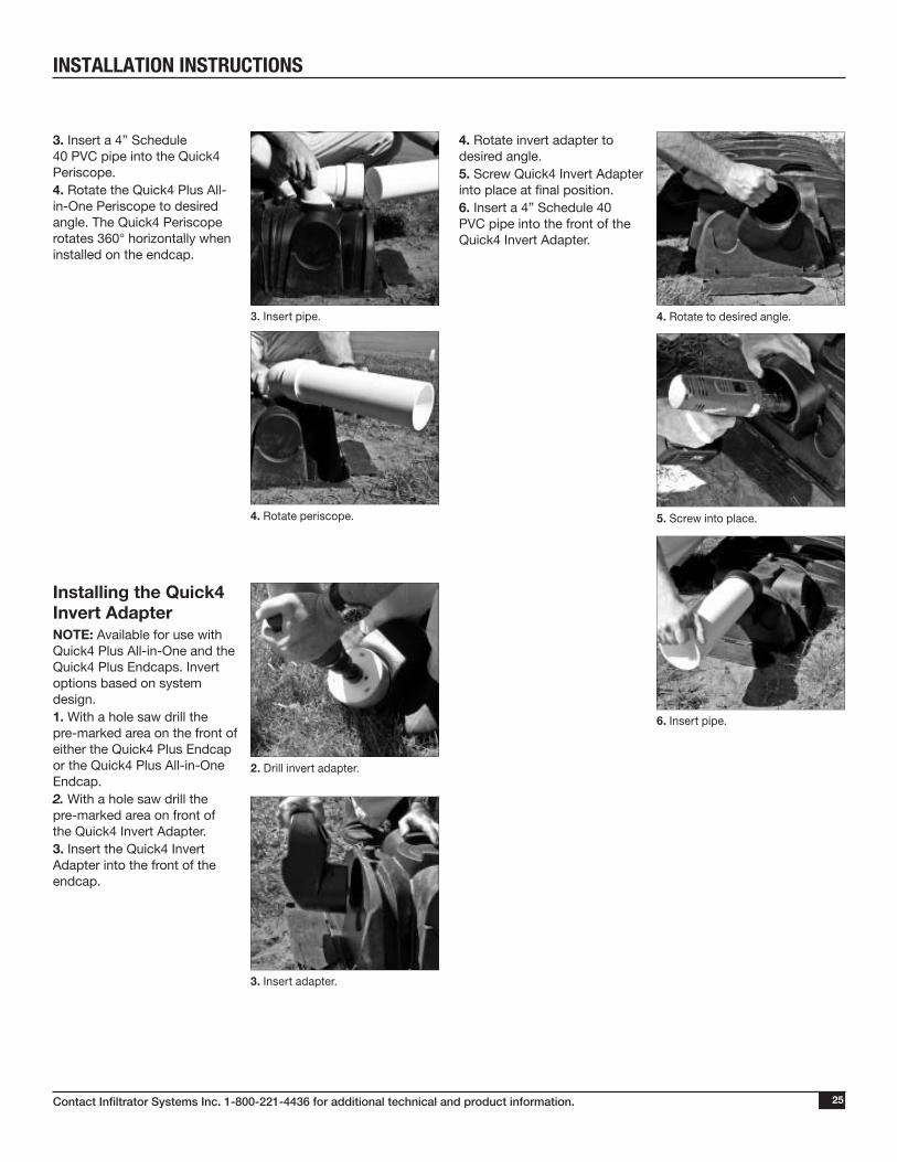
3. Insert a 4” Schedule 40 PVC pipe into the Quick4 Periscope. 4. Rotate the Quick4 Plus All-in-One Periscope to desired angle. The Quick4 Periscope rotates 360° horizontally when installed on the endcap.
Installing the Quick4 Invert AdapterNOTE: Available for use with Quick4 Plus All-in-One and the Quick4 Plus Endcaps. Invert options based on system design.1. With a hole saw drill the pre-marked area on the front of either the Quick4 Plus Endcap or the Quick4 Plus All-in-One Endcap.2. With a hole saw drill the pre-marked area on front of the Quick4 Invert Adapter. 3. Insert the Quick4 Invert Adapter into the front of the endcap.
3. Insert pipe.
4. Rotate periscope.
3. Insert adapter.
5. Screw into place.
2. Drill invert adapter.
4. Rotate to desired angle.
6. Insert pipe.
INSTALLATION INSTRUCTIONS
Contact Infiltrator Systems Inc. 1-800-221-4436 for additional technical and product information.26
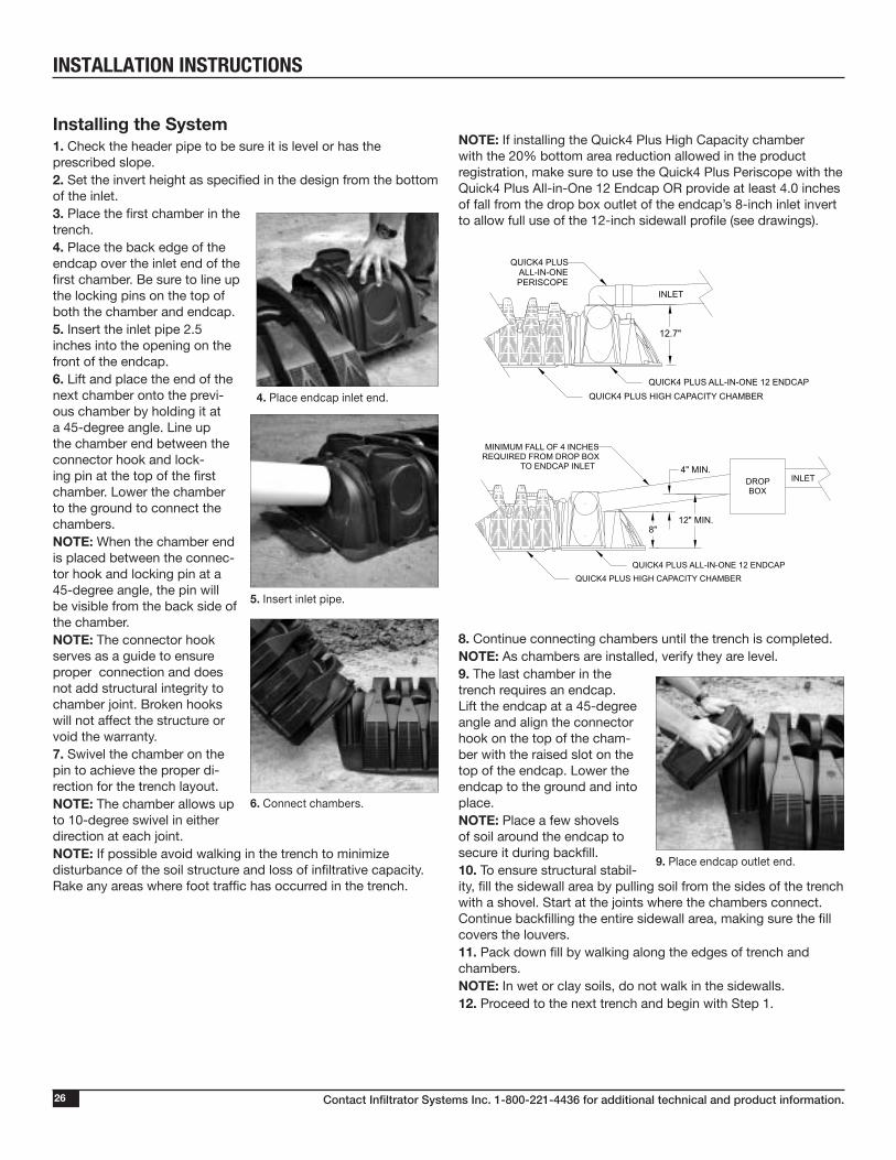
Installing the System1. Check the header pipe to be sure it is level or has the prescribed slope.2. Set the invert height as specified in the design from the bottom of the inlet.3. Place the first chamber in the trench.4. Place the back edge of the endcap over the inlet end of the first chamber. Be sure to line up the locking pins on the top of both the chamber and endcap. 5. Insert the inlet pipe 2.5 inches into the opening on the front of the endcap.6. Lift and place the end of the next chamber onto the previ-ous chamber by holding it at a 45-degree angle. Line up the chamber end between the connector hook and lock-ing pin at the top of the first chamber. Lower the chamber to the ground to connect the chambers. NOTE: When the chamber end is placed between the connec-tor hook and locking pin at a 45-degree angle, the pin will be visible from the back side of the chamber. NOTE: The connector hook serves as a guide to ensure proper connection and does not add structural integrity to chamber joint. Broken hooks will not affect the structure or void the warranty.7. Swivel the chamber on the pin to achieve the proper di-rection for the trench layout.NOTE: The chamber allows up to 10-degree swivel in either direction at each joint.NOTE: If possible avoid walking in the trench to minimize disturbance of the soil structure and loss of infiltrative capacity. Rake any areas where foot traffic has occurred in the trench.
4. Place endcap inlet end.
NOTE: If installing the Quick4 Plus High Capacity chamber with the 20% bottom area reduction allowed in the product registration, make sure to use the Quick4 Plus Periscope with the Quick4 Plus All-in-One 12 Endcap OR provide at least 4.0 inches of fall from the drop box outlet of the endcap’s 8-inch inlet invert to allow full use of the 12-inch sidewall profile (see drawings).
8. Continue connecting chambers until the trench is completed.NOTE: As chambers are installed, verify they are level.9. The last chamber in the trench requires an endcap. Lift the endcap at a 45-degree angle and align the connector hook on the top of the cham-ber with the raised slot on the top of the endcap. Lower the endcap to the ground and into place.NOTE: Place a few shovels of soil around the endcap to secure it during backfill.10. To ensure structural stabil-ity, fill the sidewall area by pulling soil from the sides of the trench with a shovel. Start at the joints where the chambers connect. Continue backfilling the entire sidewall area, making sure the fill covers the louvers.11. Pack down fill by walking along the edges of trench and chambers.NOTE: In wet or clay soils, do not walk in the sidewalls.12. Proceed to the next trench and begin with Step 1.
6. Connect chambers.
5. Insert inlet pipe.
MINIMUM FALL OF 4 INCHESREQUIRED FROM DROP BOX
TO ENDCAP INLETINLETDROP
BOX
QUICK4 PLUS HIGH CAPACITY CHAMBERQUICK4 PLUS ALL-IN-ONE 12 ENDCAP
QUICK4 PLUS HIGH CAPACITY CHAMBERQUICK4 PLUS ALL-IN-ONE 12 ENDCAP
QUICK4 PLUSALL-IN-ONEPERISCOPE
INLET
12.7"
8"
4" MIN.
12" MIN.
MINIMUM FALL OF 4 INCHESREQUIRED FROM DROP BOX
TO ENDCAP INLETINLETDROP
BOX
QUICK4 PLUS HIGH CAPACITY CHAMBERQUICK4 PLUS ALL-IN-ONE 12 ENDCAP
QUICK4 PLUS HIGH CAPACITY CHAMBERQUICK4 PLUS ALL-IN-ONE 12 ENDCAP
QUICK4 PLUSALL-IN-ONEPERISCOPE
INLET
12.7"
8"
4" MIN.
12" MIN.
9. Place endcap outlet end.
INSTALLATION INSTRUCTIONS
Contact Infiltrator Systems Inc. 1-800-221-4436 for additional technical and product information. 27
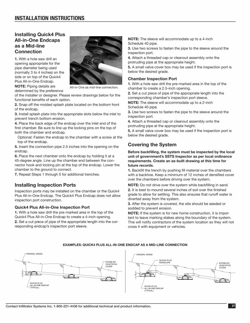
Installing Quick4 Plus All-in-One Endcaps as a Mid-line Connection1. With a hole saw drill an opening appropriate for the pipe diameter being used (normally 3 to 4 inches) on the side or on top of the Quick4 Plus All-in-One Endcap.NOTE: Piping details are determined by the preference of the installer or designer. Please review drawings below for the functional benefits of each option.2. Snap off the molded splash plate located on the bottom front of the endcap.3. Install splash plate into the appropriate slots below the inlet to prevent trench bottom erosion.4. Place the back edge of the endcap over the inlet end of the first chamber. Be sure to line up the locking pins on the top of both the chamber and endcap.
Optional: Fasten the endcap to the chamber with a screw at the top of the endcap.
5. Insert the connection pipe 2.5 inches into the opening on the endcap.6. Place the next chamber onto the endcap by holding it at a 45-degree angle. Line up the chamber end between the con-nector hook and locking pin at the top of the endcap. Lower the chamber to the ground to connect. 7. Repeat Steps 1 through 5 for additional trenches.
Installing Inspection PortsInspection ports may be installed on the chamber or the Quick4 Plus All-in-One Endcap. The Quick4 Plus Endcap does not allow inspection port construction.
Quick4 Plus All-in-One Inspection Port1. With a hole saw drill the pre-marked area in the top of the Quick4 Plus All-in-One Endcap to create a 4-inch opening.2. Set a cut piece of pipe of the appropriate length into the cor-responding endcap’s inspection port sleeve.
All-in-One as mid-line connection.
NOTE: The sleeve will accommodate up to a 4-inch Schedule 40 pipe.3. Use two screws to fasten the pipe to the sleeve around the inspection port.4. Attach a threaded cap or cleanout assembly onto the protruding pipe at the appropriate height.5. A small valve cover box may be used if the inspection port is below the desired grade.
Chamber Inspection Port1. With a hole saw drill the pre-marked area in the top of the chamber to create a 2.5-inch opening.2. Set a cut piece of pipe of the appropriate length into the corresponding chamber’s inspection port sleeve.NOTE: The sleeve will accommodate up to a 2-inch Schedule 40 pipe.3. Use two screws to fasten the pipe to the sleeve around the inspection port.4. Attach a threaded cap or cleanout assembly onto the protruding pipe at the appropriate height.5. A small valve cover box may be used if the inspection port is below the desired grade.
Covering the SystemBefore backfilling, the system must be inspected by the local unit of government’s SSTS Inspector as per local ordinance requirements. Create an as-built drawing at this time for future records.1. Backfill the trench by pushing fill material over the chambers with a backhoe. Keep a minimum of 12 inches of densified cover over the chambers before driving over the system.
NOTE: Do not drive over the system while backfilling in sand.2. It is best to mound several inches of soil over the finished grade to allow for settling. This also ensures that runoff water is diverted away from the system.3. After the system is covered, the site should be seeded or sodded to prevent erosion.NOTE: If the system is for new home construction, it is impor-tant to leave marking stakes along the boundary of the system. This will notify contractors of the system location so they will not cross it with equipment or vehicles.
EXAMPLES: QUICK4 PLUS ALL-IN-ONE ENDCAP AS A MID-LINE CONNECTION
QUICK4 PLUS ALL-IN-ONE ENDCAP(TYPICAL)
ESTABLISH VEGETATIVE COVER
ESTABLISH VEGETATIVE COVER
ORIGINAL GRADE
ORIGINAL GRADE
QUICK4 PLUS ALL-IN-ONE ENDCAP(TYPICAL)
QUICK4 PLUSPERISCOPE
8"
8"
QUICK4 PLUS ALL-IN-ONE ENDCAP(TYPICAL)
ESTABLISH VEGETATIVE COVER
ESTABLISH VEGETATIVE COVER
ORIGINAL GRADE
ORIGINAL GRADE
QUICK4 PLUS ALL-IN-ONE ENDCAP(TYPICAL)
QUICK4 PLUSPERISCOPE
8"
8"
INSTALLATION INSTRUCTIONS
Contact Infiltrator Systems Inc. 1-800-221-4436 for additional technical and product information.28
Quick4 Plus Pressure SystemsFor video instructions on the installation of pressure pipe in a Quick4 Plus chamber system, please see our installation video at www.youtube.com/infiltratorsysinc
Before You BeginQuick4 Plus chambers can only be installed according to state and/or local regulations. Soil and site conditions must be approved prior to installation. Conduct a thorough site evaluation to determine proper sizing and siting of the sys-tem before installation.
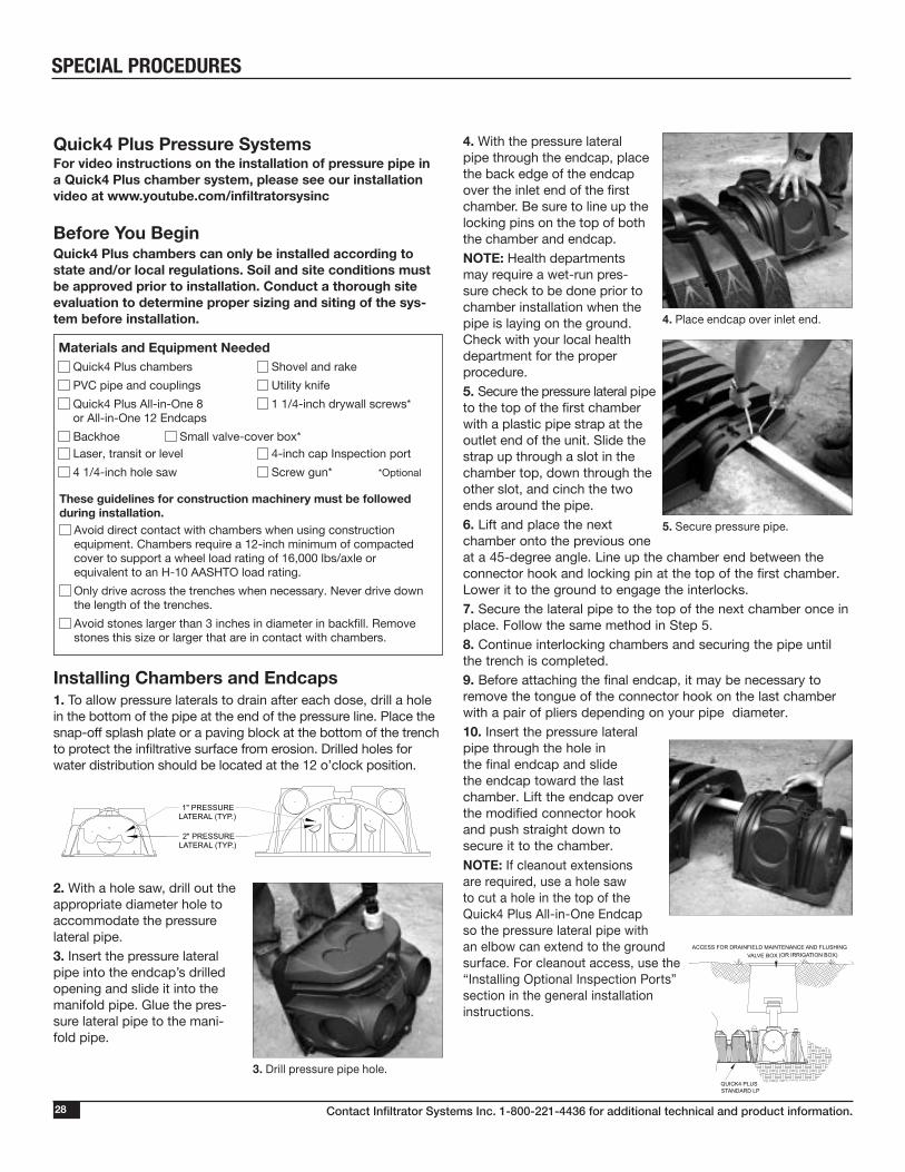
Installing Chambers and Endcaps1. To allow pressure laterals to drain after each dose, drill a hole in the bottom of the pipe at the end of the pressure line. Place the snap-off splash plate or a paving block at the bottom of the trench to protect the infiltrative surface from erosion. Drilled holes for water distribution should be located at the 12 o’clock position.
2. With a hole saw, drill out the appropriate diameter hole to accommodate the pressure lateral pipe.3. Insert the pressure lateral pipe into the endcap’s drilled opening and slide it into the manifold pipe. Glue the pres-sure lateral pipe to the mani-fold pipe.
4. With the pressure lateral pipe through the endcap, place the back edge of the endcap over the inlet end of the first chamber. Be sure to line up the locking pins on the top of both the chamber and endcap.NOTE: Health departments may require a wet-run pres-sure check to be done prior to chamber installation when the pipe is laying on the ground. Check with your local health department for the proper procedure. 5. Secure the pressure lateral pipe to the top of the first chamber with a plastic pipe strap at the outlet end of the unit. Slide the strap up through a slot in the chamber top, down through the other slot, and cinch the two ends around the pipe.6. Lift and place the next chamber onto the previous one at a 45-degree angle. Line up the chamber end between the connector hook and locking pin at the top of the first chamber. Lower it to the ground to engage the interlocks.7. Secure the lateral pipe to the top of the next chamber once in place. Follow the same method in Step 5.8. Continue interlocking chambers and securing the pipe until the trench is completed.9. Before attaching the final endcap, it may be necessary to remove the tongue of the connector hook on the last chamber with a pair of pliers depending on your pipe diameter.10. Insert the pressure lateral pipe through the hole in the final endcap and slide the endcap toward the last chamber. Lift the endcap over the modified connector hook and push straight down to secure it to the chamber.
NOTE: If cleanout extensions are required, use a hole saw to cut a hole in the top of the Quick4 Plus All-in-One Endcap so the pressure lateral pipe with an elbow can extend to the ground surface. For cleanout access, use the “Installing Optional Inspection Ports” section in the general installation instructions.
Materials and Equipment Needed Quick4 Plus chambers Shovel and rake
PVC pipe and couplings Utility knife
Quick4 Plus All-in-One 8 1 1/4-inch drywall screws*or All-in-One 12 Endcaps
Backhoe Small valve-cover box* Laser, transit or level 4-inch cap Inspection port
4 1/4-inch hole saw Screw gun* *Optional
These guidelines for construction machinery must be followed during installation.
Avoid direct contact with chambers when using construction equipment. Chambers require a 12-inch minimum of compacted cover to support a wheel load rating of 16,000 lbs/axle or equivalent to an H-10 AASHTO load rating.
Only drive across the trenches when necessary. Never drive down the length of the trenches.
Avoid stones larger than 3 inches in diameter in backfill. Remove stones this size or larger that are in contact with chambers.
1" PRESSURELATERAL (TYP.)
2" PRESSURELATERAL (TYP.)
3. Drill pressure pipe hole.
5. Secure pressure pipe.
4. Place endcap over inlet end.
VALVE BOX (OR IRRIGATION BOX)ACCESS FOR DRAINFIELD MAINTENANCE AND FLUSHING
QUICK4 PLUS STANDARD LP
SPECIAL PROCEDURES
Contact Infiltrator Systems Inc. 1-800-221-4436 for additional technical and product information. 29
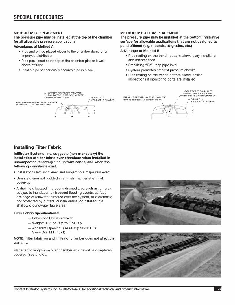
METHOD A: TOP PLACEMENT The pressure pipe may be installed at the top of the chamber for all allowable pressure applicationsAdvantages of Method A • Pipe and orifice placed closer to the chamber dome offer
improved distribution • Pipe positioned at the top of the chamber places it well
above effluent • Plastic pipe hanger easily secures pipe in place
METHOD B: BOTTOM PLACEMENT The pressure pipe may be installed at the bottom infiltrative surface for allowable applications that are not designed to pond effluent (e.g. mounds, at-grades, etc.) Advantage of Method B • Pipe resting on the trench bottom allows easy installation
and maintenance • Stabilizing “T’s” keep pipe level • System promotes efficient pressure checks • Pipe resting on the trench bottom allows easier
inspections if monitoring ports are installed
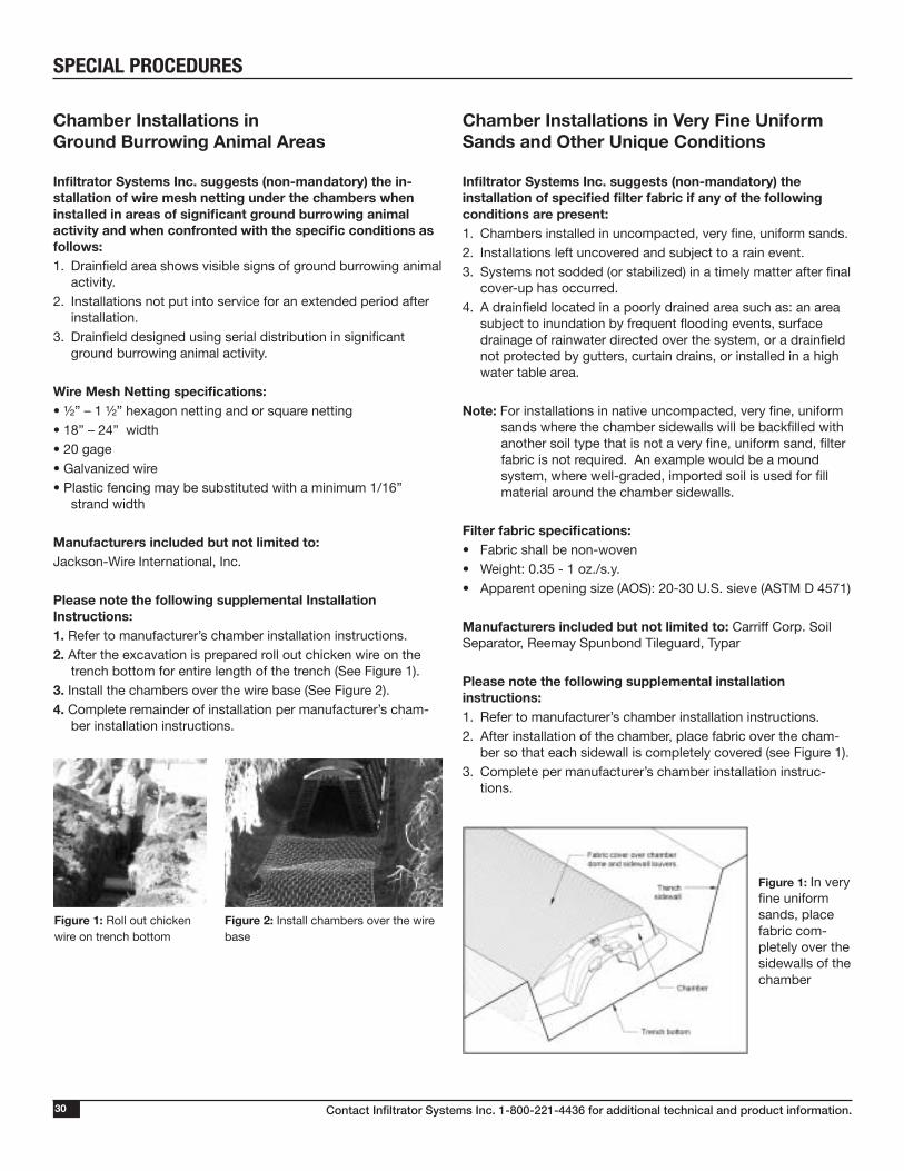
Installing Filter Fabric
Infiltrator Systems, Inc. suggests (non-mandatory) the installation of filter fabric over chambers when installed in uncompacted, fine/very-fine uniform sands, and when the following conditions exist:
• Installations left uncovered and subject to a major rain event
• Drainfield area not sodded in a timely manner after final cover-up
• A drainfield located in a poorly drained area such as: an area subject to inundation by frequent flooding events, surface drainage of rainwater directed over the system, or a drainfield not protected by gutters, curtain drains, or installed in a shallow groundwater table area
Filter Fabric Specifications:— Fabric shall be non-woven— Weight: 0.35 oz./s.y. to 1 oz./s.y.— Apparent Opening Size (AOS): 20-30 U.S.
Sieve (ASTM D 4571)
NOTE: Filter fabric on and Infiltrator chamber does not affect the warranty.
Place fabric lengthwise over chamber so sidewall is completely covered. See photos.
QUICK4 PLUS STANDARD LP CHAMBER
STABILIZE OR "T" EVERY 10' TO PREVENT PIPE ROTATION AND MAINTAIN PROPER PIPE POSITION
34"
8"
34"
8"
QUICK4 PLUS STANDARD LP CHAMBER
ALL WEATHER PLASTIC PIPE STRAP WITH120 POUNDS TENSILE STRENGTH AT EVERYCHAMBER CONNECTION
PRESSURE PIPE WITH HOLES AT 12 O’CLOCK(MAY BE INSTALLED ON EITHER SIDE)
PRESSURE PIPE WITH HOLES AT 12 O’CLOCK(MAY BE INSTALLED ON EITHER SIDE)
QUICK4 PLUS STANDARD LP CHAMBER
STABILIZE OR "T" EVERY 10' TO PREVENT PIPE ROTATION AND MAINTAIN PROPER PIPE POSITION
34"
8"
34"
8"
QUICK4 PLUS STANDARD LP CHAMBER
ALL WEATHER PLASTIC PIPE STRAP WITH120 POUNDS TENSILE STRENGTH AT EVERYCHAMBER CONNECTION
PRESSURE PIPE WITH HOLES AT 12 O’CLOCK(MAY BE INSTALLED ON EITHER SIDE)
PRESSURE PIPE WITH HOLES AT 12 O’CLOCK(MAY BE INSTALLED ON EITHER SIDE)
SPECIAL PROCEDURES
Contact Infiltrator Systems Inc. 1-800-221-4436 for additional technical and product information.30
SPECIAL PROCEDURES
Chamber Installations in Ground Burrowing Animal Areas
Infiltrator Systems Inc. suggests (non-mandatory) the in-stallation of wire mesh netting under the chambers when installed in areas of significant ground burrowing animal activity and when confronted with the specific conditions as follows:1. Drainfield area shows visible signs of ground burrowing animal
activity.2. Installations not put into service for an extended period after
installation.3. Drainfield designed using serial distribution in significant
ground burrowing animal activity.
Wire Mesh Netting specifications: • ½” – 1 ½” hexagon netting and or square netting• 18” – 24” width• 20 gage• Galvanized wire• Plastic fencing may be substituted with a minimum 1/16”
strand width
Manufacturers included but not limited to: Jackson-Wire International, Inc.
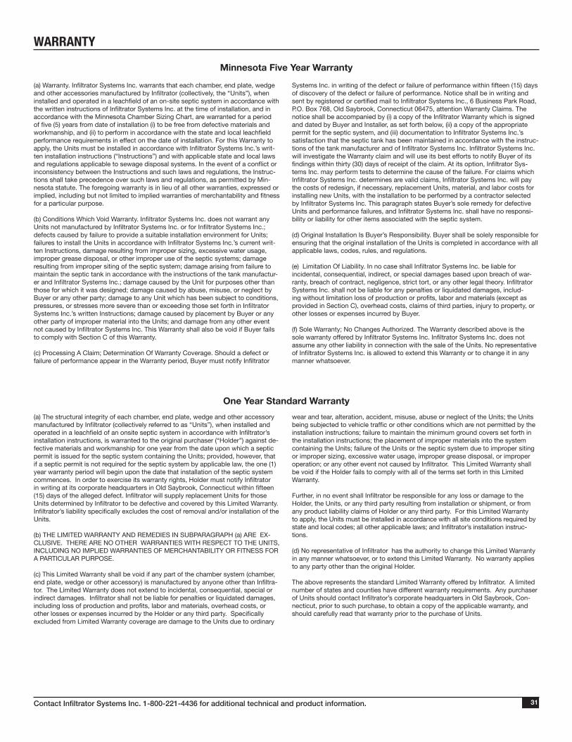
Please note the following supplemental Installation Instructions:1. Refer to manufacturer’s chamber installation instructions.2. After the excavation is prepared roll out chicken wire on the
trench bottom for entire length of the trench (See Figure 1).3. Install the chambers over the wire base (See Figure 2).4. Complete remainder of installation per manufacturer’s cham-
ber installation instructions.
Chamber Installations in Very Fine Uniform Sands and Other Unique Conditions
Infiltrator Systems Inc. suggests (non-mandatory) the installation of specified filter fabric if any of the following conditions are present:1. Chambers installed in uncompacted, very fine, uniform sands.2. Installations left uncovered and subject to a rain event.3. Systems not sodded (or stabilized) in a timely matter after final
cover-up has occurred.4. A drainfield located in a poorly drained area such as: an area
subject to inundation by frequent flooding events, surface drainage of rainwater directed over the system, or a drainfield not protected by gutters, curtain drains, or installed in a high water table area.
Note: For installations in native uncompacted, very fine, uniform sands where the chamber sidewalls will be backfilled with another soil type that is not a very fine, uniform sand, filter fabric is not required. An example would be a mound system, where well-graded, imported soil is used for fill material around the chamber sidewalls.
Filter fabric specifications: • Fabric shall be non-woven• Weight: 0.35 - 1 oz./s.y.• Apparent opening size (AOS): 20-30 U.S. sieve (ASTM D 4571)
Manufacturers included but not limited to: Carriff Corp. Soil Separator, Reemay Spunbond Tileguard, Typar
Please note the following supplemental installation instructions:1. Refer to manufacturer’s chamber installation instructions.2. After installation of the chamber, place fabric over the cham-
ber so that each sidewall is completely covered (see Figure 1).3. Complete per manufacturer’s chamber installation instruc-
tions.
Figure 1: Roll out chicken wire on trench bottom
Figure 2: Install chambers over the wire base
Figure 1: In very fine uniform sands, place fabric com-pletely over the sidewalls of the chamber
Contact Infiltrator Systems Inc. 1-800-221-4436 for additional technical and product information. 31
(a) The structural integrity of each chamber, end plate, wedge and other accessory manufactured by Infiltrator (collectively referred to as “Units”), when installed and operated in a leachfield of an onsite septic system in accordance with Infiltrator’s installation instructions, is warranted to the original purchaser (“Holder”) against de-fective materials and workmanship for one year from the date upon which a septic permit is issued for the septic system containing the Units; provided, however, that if a septic permit is not required for the septic system by applicable law, the one (1) year warranty period will begin upon the date that installation of the septic system commences. In order to exercise its warranty rights, Holder must notify Infiltrator in writing at its corporate headquarters in Old Saybrook, Connecticut within fifteen (15) days of the alleged defect. Infiltrator will supply replacement Units for those Units determined by Infiltrator to be defective and covered by this Limited Warranty. Infiltrator’s liability specifically excludes the cost of removal and/or installation of the Units.
(b) THE LIMITED WARRANTY AND REMEDIES IN SUBPARAGRAPH (a) ARE EX-CLUSIVE. THERE ARE NO OTHER WARRANTIES WITH RESPECT TO THE UNITS, INCLUDING NO IMPLIED WARRANTIES OF MERCHANTABILITY OR FITNESS FOR A PARTICULAR PURPOSE.
(c) This Limited Warranty shall be void if any part of the chamber system (chamber, end plate, wedge or other accessory) is manufactured by anyone other than Infiltra-tor. The Limited Warranty does not extend to incidental, consequential, special or indirect damages. Infiltrator shall not be liable for penalties or liquidated damages, including loss of production and profits, labor and materials, overhead costs, or other losses or expenses incurred by the Holder or any third party. Specifically excluded from Limited Warranty coverage are damage to the Units due to ordinary
wear and tear, alteration, accident, misuse, abuse or neglect of the Units; the Units being subjected to vehicle traffic or other conditions which are not permitted by the installation instructions; failure to maintain the minimum ground covers set forth in the installation instructions; the placement of improper materials into the system containing the Units; failure of the Units or the septic system due to improper siting or improper sizing, excessive water usage, improper grease disposal, or improper operation; or any other event not caused by Infiltrator. This Limited Warranty shall be void if the Holder fails to comply with all of the terms set forth in this Limited Warranty.
Further, in no event shall Infiltrator be responsible for any loss or damage to the Holder, the Units, or any third party resulting from installation or shipment, or from any product liability claims of Holder or any third party. For this Limited Warranty to apply, the Units must be installed in accordance with all site conditions required by state and local codes; all other applicable laws; and Infiltrator’s installation instruc-tions.
(d) No representative of Infiltrator has the authority to change this Limited Warranty in any manner whatsoever, or to extend this Limited Warranty. No warranty applies to any party other than the original Holder.
The above represents the standard Limited Warranty offered by Infiltrator. A limited number of states and counties have different warranty requirements. Any purchaser of Units should contact Infiltrator’s corporate headquarters in Old Saybrook, Con-necticut, prior to such purchase, to obtain a copy of the applicable warranty, and should carefully read that warranty prior to the purchase of Units.
WARRANTY
(a) Warranty. Infiltrator Systems Inc. warrants that each chamber, end plate, wedge and other accessories manufactured by Infiltrator (collectively, the “Units”), when installed and operated in a leachfield of an on-site septic system in accordance with the written instructions of Infiltrator Systems Inc. at the time of installation, and in accordance with the Minnesota Chamber Sizing Chart, are warranted for a period of five (5) years from date of installation (i) to be free from defective materials and workmanship, and (ii) to perform in accordance with the state and local leachfield performance requirements in effect on the date of installation. For this Warranty to apply, the Units must be installed in accordance with Infiltrator Systems Inc.’s writ-ten installation instructions (“Instructions”) and with applicable state and local laws and regulations applicable to sewage disposal systems. In the event of a conflict or inconsistency between the Instructions and such laws and regulations, the Instruc-tions shall take precedence over such laws and regulations, as permitted by Min-nesota statute. The foregoing warranty is in lieu of all other warranties, expressed or implied, including but not limited to implied warranties of merchantability and fitness for a particular purpose.
(b) Conditions Which Void Warranty. Infiltrator Systems Inc. does not warrant any Units not manufactured by Infiltrator Systems Inc. or for Infiltrator Systems Inc.; defects caused by failure to provide a suitable installation environment for Units; failures to install the Units in accordance with Infiltrator Systems Inc.’s current writ-ten Instructions, damage resulting from improper sizing, excessive water usage, improper grease disposal, or other improper use of the septic systems; damage resulting from improper siting of the septic system; damage arising from failure to maintain the septic tank in accordance with the instructions of the tank manufactur-er and Infiltrator Systems Inc.; damage caused by the Unit for purposes other than those for which it was designed; damage caused by abuse, misuse, or neglect by Buyer or any other party; damage to any Unit which has been subject to conditions, pressures, or stresses more severe than or exceeding those set forth in Infiltrator Systems Inc.’s written Instructions; damage caused by placement by Buyer or any other party of improper material into the Units; and damage from any other event not caused by Infiltrator Systems Inc. This Warranty shall also be void if Buyer fails to comply with Section C of this Warranty.
(c) Processing A Claim; Determination Of Warranty Coverage. Should a defect or failure of performance appear in the Warranty period, Buyer must notify Infiltrator
Systems Inc. in writing of the defect or failure of performance within fifteen (15) days of discovery of the defect or failure of performance. Notice shall be in writing and sent by registered or certified mail to Infiltrator Systems Inc., 6 Business Park Road, P.O. Box 768, Old Saybrook, Connecticut 06475, attention Warranty Claims. The notice shall be accompanied by (i) a copy of the Infiltrator Warranty which is signed and dated by Buyer and Installer, as set forth below, (ii) a copy of the appropriate permit for the septic system, and (iii) documentation to Infiltrator Systems Inc.’s satisfaction that the septic tank has been maintained in accordance with the instruc-tions of the tank manufacturer and of Infiltrator Systems Inc. Infiltrator Systems Inc. will investigate the Warranty claim and will use its best efforts to notify Buyer of its findings within thirty (30) days of receipt of the claim. At its option, Infiltrator Sys-tems Inc. may perform tests to determine the cause of the failure. For claims which Infiltrator Systems Inc. determines are valid claims, Infiltrator Systems Inc. will pay the costs of redesign, if necessary, replacement Units, material, and labor costs for installing new Units, with the installation to be performed by a contractor selected by Infiltrator Systems Inc. This paragraph states Buyer’s sole remedy for defective Units and performance failures, and Infiltrator Systems Inc. shall have no responsi-bility or liability for other items associated with the septic system.
(d) Original Installation Is Buyer’s Responsibility. Buyer shall be solely responsible for ensuring that the original installation of the Units is completed in accordance with all applicable laws, codes, rules, and regulations.
(e) Limitation Of Liability. In no case shall Infiltrator Systems Inc. be liable for incidental, consequential, indirect, or special damages based upon breach of war-ranty, breach of contract, negligence, strict tort, or any other legal theory. Infiltrator Systems Inc. shall not be liable for any penalties or liquidated damages, includ-ing without limitation loss of production or profits, labor and materials (except as provided in Section C), overhead costs, claims of third parties, injury to property, or other losses or expenses incurred by Buyer.
(f) Sole Warranty; No Changes Authorized. The Warranty described above is the sole warranty offered by Infiltrator Systems Inc. Infiltrator Systems Inc. does not assume any other liability in connection with the sale of the Units. No representative of Infiltrator Systems Inc. is allowed to extend this Warranty or to change it in any manner whatsoever.
Minnesota Five Year Warranty
One Year Standard Warranty

Contact Infiltrator Systems’ Technical Services Department for assistance at 1-800-221-4436
4 Business Park Road P.O. Box 768 Old Saybrook, CT 06475860-577-7000 • Fax 860-577-70011-800-221-4436www.infiltratorsystems.com
U.S. Patents: 4,759,661; 5,017,041; 5,156,488; 5,336,017; 5,401,116; 5,401,459; 5,511,903; 5,716,163; 5,588,778; 5,839,844 Canadian Patents: 1,329,959; 2,004,564 Other patents pending. Infiltrator, Equalizer, Quick4, and SideWinder are registered trademarks of Infiltrator Systems, Inc. Infiltrator is a registered trademark in France. Infiltrator Systems, Inc. is a registered trademark in Mexico. Contour, MicroLeaching, PolyTuff, ChamberSpacer, MultiPort, PosiLock, QuickCut, QuickPlay, SnapLock and StraightLock are trademarks of Infiltrator Systems, Inc. PolyLok is a trademark of PolyLok, Inc. TUF-TITE is a registered trademark of TUF-TITE, INC. Ultra-Rib is a trademark of IPEX Inc.
© 2014 Infiltrator Systems, Inc. All rights reserved. Printed in U.S.A. C95 0814ISI