Embed Size (px)
Citation preview

RD-R144 273 DESIGN AND MANUFACTURE OF 5 MM MODULAR PROPELLIN ICHARGES(U) ARfITEC DEFENSE PRODUCTS INC COACHELLA CAJ E HALEY AUG 84 ARLCD-CR-84014 DAAKIO-82-C-0258
UNCLASSIFIED F/G 19/ NL
W J0
11110 1.0.0I1.25IM13
MIRCP REOUTO TES CHRNAINLBREUO TNDRS16-
ADAD-MI 192
CONTRACTOR REPORT ARLCD-CR-4014
DESIGN AND MANUFACTURE OF 155-MM MODULARPROPELLING CHARGES
JACK HALEY
ARMTEC DEFENSE PRODUCTS CO.85-901 AVENUE 53, P.O. BOX 848
COACHELLA. CA 92236
AUGUST 1984
U.S. ARMY ARMAMENT RESEARCH AND DEVELOPMENT CENTERLARGE CAUSERt WEAPIE SYSTEMS HiLORATORT
DOWER, EW mRSYn
APPROVED FOR PUBLIC RELEASE: DISTRIBUTION UNLIMITED.
+_DTIClb JUL 31 1984
B
.84 07 3T 003

The views, opinions, and/or findings contained inthis report are those of the author(s) and shouldnot be construed as an official Department of theArmy position, policy, or decision, unless sodesignated by other documentation.
The citation in this report of the names ofcommercial firms or commercially availableproducts or services does not constitute officialendorsement by or approval of the U.S.Government.
Destroy this report when no longer needed. Donot return to the originator.
4lw4.
6 I I J i il I i I . . . . .....
777
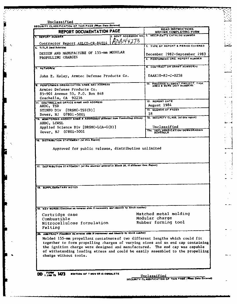
Unclassif iedSECURITY CLASSIFICATION OF THIS PAGE (When Data Entered)
DCM TTOPGREAD INSTRUCTIONSREPORT DOCUMENTATION PAGE BEFORE COMPLETING FORM
F REPORT NUMBER 2. GOVT ACCESSION NO. 3. RECIPIENT'S CATALOG NUMBER
Contractor Report ARLCD-CR-840144. TITLE (,d Subttle) 5. TYPE OF REPORT & PERIOD COVERED
DESIGN AND MANUFACTURE OF 155-mm MODULAR December 1982-September 1983
PROPELLING CHARGES• PROPLLING HARGESS. PERFORMING ORG. R'EPORT NUMBER "
7. AUTHOR(s) S. CONTRACT OR GWANT NUMBER(s)
John E. Haley, Armtec Defense Products Co. DAAKIO-82-C-0258
9. PERFORMING ORGANIZATION NAME AND ADDRESS 10. PROGRAM ELEMENT PROJECT, TASKAREA & WORK UNIT NUMBERS
Armtec Defense Products Co.
85-901 Avenue 53, P.O. Box 848
Coachella, CA 92236 -
It. CONTROLLING OFFICE NAME AND ADDRESS 12. REPORT DATE
ARDC, TSD August 1984
STINFO Div [DRSMC-TSS(D)j S. NUMBER OF PAGES
Dover, NJ 07801-5001 18
-4. MONITORING AGENCY NAME & ADDRESS(If dlliemnt from Cont, lling Office) IS. SECURITY CLASS. (of this report)
ARDC, LCWSLApplied Science Div [DRSMC-LCA-G(D)] Unclassified
Dover, NJ 07801-5001 ISa. DECLASSIFICATION/ DOWNGRADING.oeSCHEDULE
16. DISTRIBUTION STATEMENT (of thie Report)
Approved for public release, distribution unlimited
?. DISTRIBUTION STATEMENT (of the abstract entered In Block 20, If different from Report)
18. SUPPLEMENTARY NOTES
19. KEY WORDS (Continue on revere, side It n.c.sary ,nd identify by block numbe)
Cartridge case Matched metal molding
Combustible Modular charge
Nitrocellulose formulation Rubber forming toolFelting
2L. ATrRACT" (ciati am revera N nmevemy end Ident.iY" by block number)
Molded 155-mm propellant containers of two different lengths which could fit
together to form propelling charges of varying sizes and an end cap containing
the ignition charge were designed and manufactured. The end cap was capable
of withstanding loading stress and could be easily assembled to the propelling
charge without tools.
DD , J 73 EDTI OOFI IOV6ISOSSOLETE Unclassified
SECUITY CLASSIFICATION OF TI1S PAGE (When Dots Entered)
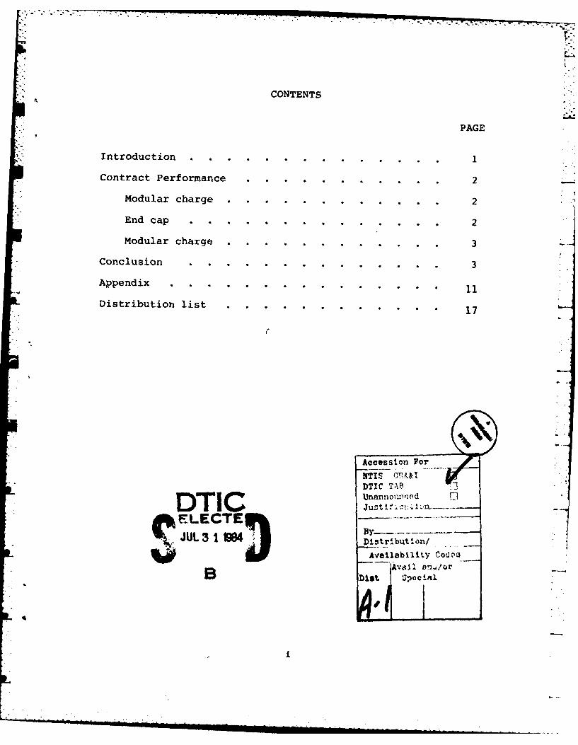
CONTENTS
PAGE
Introduction . .. .... ..........
Contract Performance . . . . . . . . . .. 2
Modular charge . . . . . . . . . . . . 2
End cap.................. ........... 2
Modular charge .......... . 3
Conclusion... ....... ......... ........... 3
Appendix ......... . ... . .. .. .... 1
Distribution list......... ......... ..... 17
Unanno,,Lied FDTICJut?: -
SFLECTEJUL 3t Di~tribut I on/
Availability Codc~a
Aviaio
INTRODUCTION
A number of 155-mm rigid molded fiber modular charge containersintended for use in advanced artillery applications were manufact-ured. The containers are designed for ease and adaptability in as-sembly for zone charge selection, will provide for in-vehicle assem-bly, and will facilitate automatic handling and loading.
The modular charges were designed and fabricated to allow buildup assembly to the higher firing zones rather than torn down to thelow firing zone. Commonality in design was required to allow themodular charges to be assembled in any order providing for immediatezone selection capability. Each modular charge (body assembly) con-sists of a body and base. In addition, the longer body was event-ually modified with button holes to allow for insertion of the endcap. The body assemblies were manufactured as follows:
a. 150 to a length of 8.06 inches (-2).
b. 300 to a length of 10.62 inches (-1).
c. 50 to a length of 10.58 inches (-1 revised) as deter-mined by the Project Engineer for study on development of a uni-length modular charge.
Also accomplished was the design, acquisition of tooling for,and manufacture of 25 end caps, which would snap in mechanically andbe retained by the rear module of the assembled zone charge, pro-viding for ramming capability while still allowing ignition access.
All parts were manufactured to the composition set forth inTable 1.
The normal beater additive molded fiber process of manufacture(appendix) was used to produce all bodies and bases. The end capswere produced by a modified process wherein the wet preform (felt)after having been felted in a female (cavity) felter, is pre-driedin an oven, allowed to stabilize to atmospheric humidity, then pressmolded in a split female die using a rubber plug under pressure as amale die, (fig. 1). This process change was instituted due to theneed to mold undercuts (attachment buttons) on the sidewalls of theend cap, (fig. 2). This process represents a tradeoff between thebag molding process currently being used by Armtec to produce theM203E2 igniter cup containers, and the dry preform process which hasbeen used for a number of years in the manufacture of other combust-ible fibre components. It is the first time a hydraulic rubber plughas been used to successfully mold combustible fibre material.
I - - - II .. -- .-
. . . . . . . . . . . . . . . °
I.
CONTRACT PERFORMANCE
Modular Charges
The initial complement of 450 bodies and bases were felted andmolded, using existing tooling that had been refurbished, with littletrouble. However, during the trimming operations, on the molded bod-ies, it was noted that age and rework on the molding tools resultedin a molded part that was fragile in some areas and untenable on anextended production basis. Male die drainage grooves had been wid-ened to approximately 0.300 inches by cleaning and rework, resultingin large drainage groove ribs and a significantly weaker sidewall.Machining of the nominally 0.080-inch-thick sidewall at the open endof the body to provide for assembly to the base, resulted in an ex-tremely thin, weak base entry area which was emphasized by any outof roundness of the part in that area, even if within drawing tol-erance. The parts were trimmed, inspected and shipped. See Tables2 and 3 for results of the inspection.
End Cap
This portion of the contract required the design, tooling for,and manufacture of 25 end caps for the open (ignition) end of thebody assembly. The end cap design was coordinated between Armtecand the ARRADCOM project engineer. The end cap is inserted into theopen end of the body. It is held in place by means of four equallyspaced sidewall protrusions (buttons) which are received by fourcorresponding holes in the body sidewall.
Tooling to produce this part required special consideration dueto the molding die undercuts caused by the sidewall protrusions.The existing process to manufacture a similar product (the M203E2igniter cup container) required a two stage molding operation con-sisting of a first stage normal die-dry molding, and a second stagebag molding operation. The process makes a very acceptable product,but is quite expensive in equipment and double tooling costs.
In order to reduce tooling costs, it was decided to attempt tomake the product by a new process utilizing a pre-dried felt (drypreform) made in a female cavity felter and molded in a basic steam-heated die jacket with the mold die being a shaped rubber plug sim-ilar to those used in the hydroforming of sheet metal. Initiallythe rubber forming plug was permanently attached to the steel pres-sure cylinder, so the plug would move with the cylinder on openingof the press. However, initial efforts with this design showed thatthe cylinder and the plug, moving as a mass upon press opening,would create wrinkles in the sidewall. This was due to the extrudedrubber (under pressure) not being able to relieve its internallybuilt-up pressure as quickly as necessary to prevent sticking to theproduct inner walls. To obviate the problem, the plug was detachedfrom the cylinder and inserted as a loose piece (fig. 1).
2
A Molding die, for the manufacture of the rubber plug itself,.5 was fabricated by Pacific Moulding Company and two rubber plugs were
,made. Molded plug diameters were not entirely correct so a methodwas devised to machine the rubber plug diameters making mold rework
* unnecessary. With the new process, machine trimming of the moldedend cap is minimal. The only trimming required is deflashing thefour button holes and trimming to length. The 25 end caps were in- ..-spected and shipped along with the final 50 body assemblies. SeeTables 2 and 3 for inspection results.
Modular Charge
The length selected for the final 50 modular charges was 10.58inches. These parts were felted, molded, inspected and tested. Thebodies were hand stretched after molding to a slightly larger out-side diameter at the open end to provide for more even trimming ofthe base-end cap receiving area. This resulted in a stronger side-wall in this location and allowed the end cap to be forced into placewith only slight tearing of the button holes in the body on assemblytrials. Assembled units were loaded with 10 pounds and 30 pounds oflead shot and drop tested from three feet. All passed with no break-age. Twenty-five were punched to receive the end cap and were ship-ped with the end caps. Inspection and testing results are reflectedin Tables 2 and 3.
Based upon the above results and anticipating the difficultiesof inserting the newly designed end cap into the existing body, thebody design was modified to allow easy insertion of the end cap.New molding and felting tools were designed and purchased to reflectthis configuration.
CONCLUSIONS
1. An end cap of snap-in construction was designed and manu-factured successfully by Armtec and ARRADCOM.
2. A new manufacturing method, Rubber Plug Molding, was de-veloped which promises to lower tooling costs on selectedproducts in the future. The rubber plug molding method issuccessful but it will require further refinement for largescale production.
3. The modular charge cartridge case design is valid and shouldbe proven out by additional production.
3
I ,,Table 1. Nominal composition
Material % by wt. Source
*Nitrocellulose, 12.6% N 72.0 ± 2.0 Radford AAP
Kraft paper, MIL-C-50269 17.0 t 2.0 Federal Paperboard Co.
"Marbon 1600" Resin 10.0 ±2.0 Revertex Ltd.
5

Table 2. Chemical and physical test results
IPDens ty Tensile
Batch NC % DPA % KRAD % g/cm psi Stability
79 69.94 1.30 28.76 1.028 2284 ok
80 71.46 0.96 27.58 0.960 2216 ok
81 69.78 1.30 28.92 1.024 2276 ok
82 70.98 1.28 27.74 0.954 2329 ok
92 71.12 1.27 27.61 0.830 2083 ok
93 71.73 1.29 26.98 0.820 1787 ok
94 71.38 1.30 27.32 0.800 1875 ok
95 71.79 1.16 27.05 0.833 1828 ok
96 71.79 1.16 27.05 N.R.* N.R.* ok
98 71.82 1.17 27.01 0.875 1780 ok
99 71.51 1.27 27.22 0.861 1728 ok
S=Density and tensile not recorded. End cap component did not
provide a large enough area to punch a sample.
NOTE!! Dead load tests on the body assembly with end cap using
loads of 10 and 30 pounds of lead shot inside the body resultedin no assembly failure, even though three of the body button holeshad been fractured inserting the end cap.
6
II
Table 3 - DIMENSIONAL INSPECTION RESULTS
(Dimensions in inches except where noted)
P/N 9344132-1. Body Rev B
DIMENSION AVERAGE HIGH LOW
Inside dia. 5.750 t 0.005 5.725 5.742 5.7125.746 5.754 5.739 "
Material thickness 0.080 t 0.016 0.082 0.091 0.072Length 10.620 t 0.020 10.602 10.618 10.591
Straightness 0.125 ok ok okDepth to shoulder 1.21 + 0.01 1.221 1.277 1.183Length froanbottonto shoulder 9.270 t 0.02 9.279 9.330 9.210Ribs within 2 inches from rear visual ok ok okEvidence of poor workmanship ok ok okO.D. 2ndshoulder from bottom 5.750 t 0.005 5.726 5.735 5.720O.D. 1st shoulder frau bottom 5.565 ± 0.005 5.535 5.560 5.473Weight - gm - (information) 256.7 267.0 239.2Length 2nd shoulder 1.125 1 0.01 1.096 1.116 1.082Length 1st shoulder 0.30 t 0.01 0.266 0.304 0.236* Refelects 25 units which were shipped with Task II End Caps.
Parts were stretched after molding.
P/N 9344132-2, Body Rev B
DIMENSION AVERAGE HIGH LOW
Inside dia. 5.750 t 0.005 5.744 5.778 5.714Inside dia. 5.680 t 0.010 5.679 5.684 5.674Material thickness 0.080 t 0.010 0.085 0.096 0.073Length 8.060 f 0.020 8.088 8.101 8.073Straightness 0.125 ok ok okDepth to shoulder 1.21 + 0.01 1.203 1.236 1.143Length from bottom to shoulder 6.750 t 0.02 6.780 6.830 6.730Ribs within 2 inches from rear visual ok ok okEvidence of poor workmanship ok ok okO.D. 2nd shoulder from bottom 5.750 t 0.005 5.732 5.741 5.722O.D. lst shoulder fran bottom 5.565 t 0.005" 5.538 5.543 " 5.530Weight - gm - (information) 199.0 206.2 190.6Length 2nd shoulder 1.125 t 0.01 1.098 1.114 1.070Length lst shoulder 0.30 t 0.01 0.280 0.292 0.263
P/N 9344130, Base Rev BDIMENSION AVERAGE HIGH LOW
Weight - gm - (information) 52.8 57.0 42.2O.D. 5.750 t 0.005 5.775 5.790 5.761I.D. 5.150 ± 0.010 5.184 5.197 5.171Depth to shoulder 0.290 t 0.010 0.299 0.313 0.286Material thickness 0.080 * 0.010 0.094 0.097 0.091Inside depth base 1.02 * 0.02 1.024 1.047 1.001Inside angle 150 1 10 150301 15030' 15030'Radius 0.062 - 0.010R 0.070 0.070 0.070Radius 0.125 - 0.010R ok ok ok
P/N 9357961. End cap Rev XA -
DIMENSION AVERAGE HIGH LOWMajor O.D. (buttons) 5.95 - 0.02 5.930 5.945 5.922Outside dia. 5.75 - 0.010 5.754 5.775 5.736Material thickness 0.100 t 0.010 0.078 0.085 0.069Ht. ring bottom to flat 0.125 * 0.010 0.159 0.170 0.148Bottom to boss 0.050 - 0.01 0.488 0.505 0.469Dia. boss 0.475 + 0.010 0.520 0.534 0.497Spacing of boss ok ok ok4 inch dia. t 0.01 ok ok okHeight (trim) 1.00 - 0.02 1.007 1.028 0.993Sidewall thickness 0.120 0.142 0.096Weight - gm - (information) 70.1 71.2 69.2Hole dia. 2.00 + 0.02 2.003 2.006 1.999
7
'0
12191____ 0 RING MATERIAL .10.3 0 tNEOPRENE
111251 _____ 3/-1 SOC. HO -CAP SCREWS SST
101 IMF~-avl-o? COVER MALE HEAT PLUG _______
911 M -'-f MALE HEAT PLUG jN. R.S.
* I *fF # SPLIT FEMALE FORMING INSERT RS?I I I MZ 7 Z FEMALE INNER STEAM JACKET N. A.S.
61 o /17-Api-va FORmVG RUBBER INEOPRENE
51 1 Swsr PLUGI IH. R.S.
4 1 oH4er j COVER INNER STEAM JACKET i .R.S.
3 1 161S-i-a FEMALE OUTERt STEAM JACKET IMRAS. _______
2 1 /4700 -1 COVER OUTER STEAM JACKET j .R.S. /55MM MODULAR CHARGEl
RUBE FORMING TOOL ASSEMBLY I VARIOUS 'RUBBER FORMING
Figure 1. 155mm Modular charge rubber forming tool
9
BODY- 9344132
CASE ASS.
W/end cat) ~-9344 130CASE ASS'Y
*9344155-2
(w/o end cap
BODY
(base end) . DETAIL OF END CAP"SNAP-IN" ON 9344155-1 -
BODY ASS'Y. END CAP USEDON -1 CONFIGURATION ONLY
BODY(front end)
DETAIL OF MODULAR JOINT
ass'y to ass )y
Figure 2. Modular charge details

APPENDIX
BEATER ADDITIVE PROCESS OF MANUFACTURE
The beater additive molded-fiber process is a manufacturing processfor making molded products using modified pulp and papermaking pro-cedures to produce an end product from mixed fibers and plastic resins.
The basic raw materials are nitrated cotton linters (Nitrocellulose)and natural cellulose fibers (Sulfite Kraft). Emulsified resins areadded as binders for strength, moisture repellency, and other desir-able characteristics. The natural fibers are hydrated and reducedto their unrefined state (i.e., individual fibers) in a beater withwater to the freeness required by subsequent processing.
Nitrocellulose is added to the Kraft paper slurry in the beater andmixed until homogeneous. Resin is added to the slurry at this timealong with the necessary chemicals and ionically precipitated to theindividual fibers. Resin particles may be precipitated to the indi-vidual fibers, either anionically or cationically dependent on resinsystem used. Best results are obtained with smaller resin particlesforming a sheath around each individual fiber, thus preventing me-chanical dislodging of the resin from the fibers during subsequentprocessing. Nitrocellulose stabilizers are also added during theprecipitation process. The slurry batch is transferred by pump fromthe precipitation tank to a large slurry supply tank where it is di-luted with water to the proper consistency for the felting operationwhich follows. A consistency of 0.2% to 0.4% is generally used al-though thinner or heavier consistencies are feltable. Ideal consis-tency is largely dependent on product configuration. 2The slurry batch is then pumped to the preforming tank. The slurryenters the tank at the bottom, fills it and overflows into a trougharound the top circumference of the tank, creating a weir action. IThe slurry then flows to a pump where the material is returned tothe supply tank on a continuous basis. This in-flow/out-flow ofslurry provides the agitation required to keep the fibers in uni-form suspension in the water. Auxiliary agitation may be necessary.
The preforming die (felter) consists of a hollow, perforated form,contoured to the part configuration, and covered with fine mesh screen.A vacuum line is connected to the hollow cavity of the die. The felt-ing die is immersed into the slurry bath. Water is drawn through thedie by vacuum, depositing the resinated fibers on the screen surface.After a predetermined time, the felter is raised out of the slurrywith the vacuum still applied for a period of time to remove most ofthe free water from the resulting preform, leaving a wet felt approx-imately 60% water, 40% dry fibers and resin. The vacuum is then shutoff and a quick, low pressure pulse of air is injected into the diecavity, stretching the preform slightly and loosening the fiber fromthe screen for easy removal of the preform. The wet preform is re-moved from the felter and placed over the male section of steamheated,matched metal molding dies, designed to produce a molded part to fin-ished product dimensions, in a press. The male die contains verticaldrainage grooves around its periphery which terminate at the base ofthe die in a vacuum manifold. -
13
The female die is slowly closed over the felt on the male die, -
forcing water from the felt through the drainage grooves to themanifold by pressure and vacuum, thus molding the part to finisheddimensions. The remaining moisture in the felt is vaporized bydie heat and evacuated through the vacuum manifold. The resin inthe product is cured at this time by the die heat. After a pre-determined time, the dies are opened, a pressure pulse of air in-jected into the die, and the molded part removed. After molding,parts are trimmed and finished, as required, to finished part con-figuration. They are inspected physically, compositionally tested,as applicable, and packed out.
14.
. .. ..
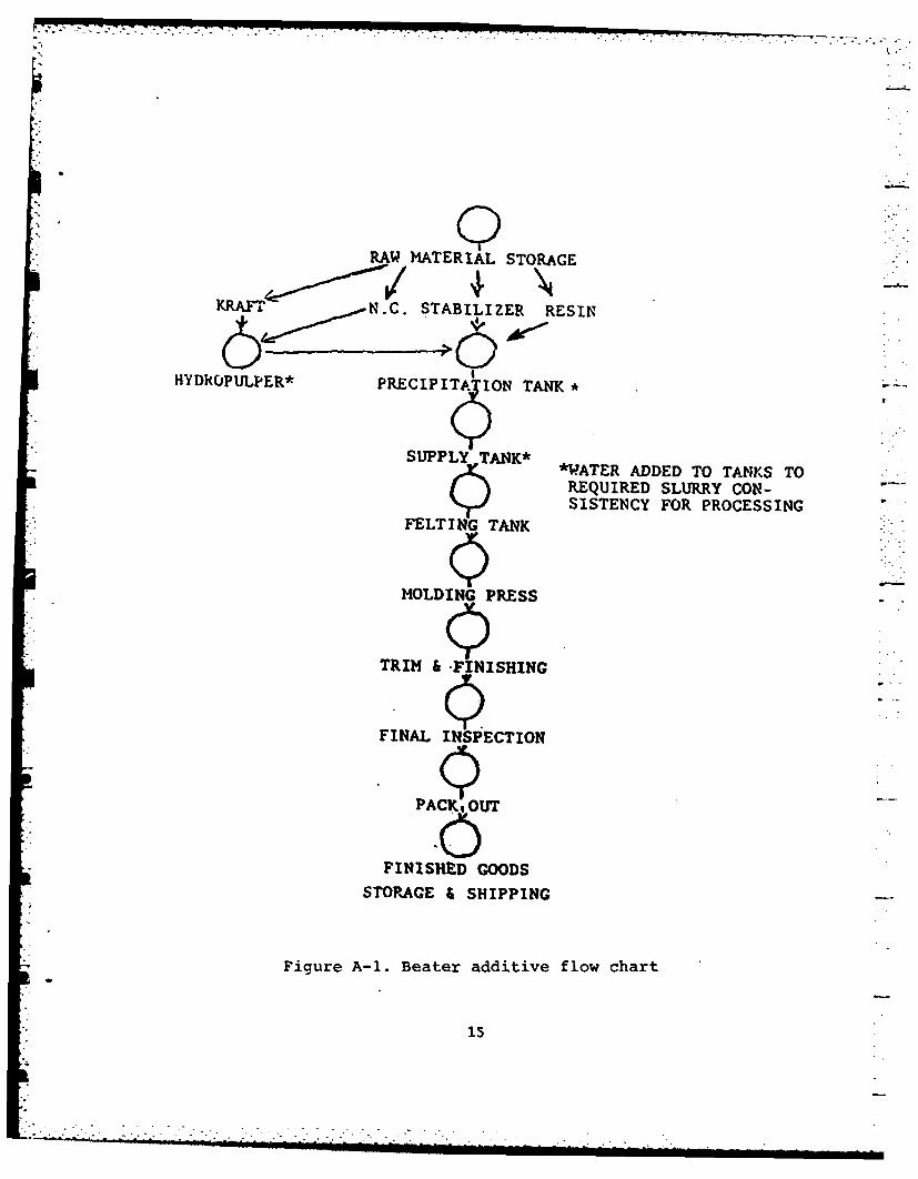
RAW MATERIAL STORAGE
KRAFT N.C. STABILIZER RESIN~
HYDRCJPULPER* PEITAONTANK
SUPPLY TANK**W.ATER ADDED TO TANKS TOREQUIRED SLURRY CON-SISTENCY FOR PROCESSING
FELTING TANK
MOLDING PRESS
TRIM & FINISHING
FINAL INSPECTION
PACK, OUT
FINISHED GOODS
STORAGE & SHIPPING
Figure A-i. Beater additive flow chart
15
DISTRIBUTION LIST
CommanderArmament Research and Development Center
U.S. Army Armament, Munitionsand Chemical Command
ATTN: DRSIC-LCA-G(D) (12)DRSMC-TSS(D) (5)
Dover, NJ 07801-5001
AdministratorDefense Technical Information CenterATTN: Accessions Division (12)Cameron StationAlexandria, VA 22314
DirectorU.S. Army Materiel Systems
Analysis ActivityATTN: DRXSY-MPAberdeen Proving Ground, MD 21005
Commander/Director
Chemical Research and Development CenterU.S. Army Armament, Munitions
and Chemical CommandATTN: DRSMC-CLJ-L(A)
DRSMC-CLB-PA(A)APG, Edgewood Area, MD 21010
DirectorBallistic Research LaboratoryATTN: DRXBR-OD-STAberdeen Proving Ground, MD 21005
ChiefBenet Weapons Laboratory, LCWSLArmament Research and Development Center
- U.S. Army Armament, Manitionsand Chemical Command
ATTN: DRSMC-LCB-TLWatervliet, NY 12189
CommanderU .S. Army Armament, Manitions
and Chemical CommandATTN: DRSC-LEP-L(R)Rock Island, IL 61299
17
DirectorU.S. Army TRADOC Systems Analysis ActivityATTN: ATMA-SL
* White Sands Missile Range, NM 88002
Armtec Defense Products CompanyATTN: John Haley (5)
Gerald Perachetz85-901 Avenue 53P.O. Box 848Coachella, CA 92236
18

$P A
-E:P 7,
A, 0 1111t 'J It
it4-
0 Wj0