Embed Size (px)
Citation preview
Politecnico di Milano
School of Industrial and Information Engineering
Master of Science in Material Engineering and Nanotechnology
_________________________________________________________________
DESIGN AND MANUFACTURING OF
A BIOINSPIRED COMPOSITE TUBE
Master Thesis dissertation:
Francesca El Louizi
818278
Supervisors:
Prof. Laura Vergani, Prof. Gerhard Ziegmann
Co-Supervisors:
PhD Flavia Libonati, Ing. Randolf Hoffmann
Academic Year 2015-2016

-1-
Index _______________________________________________________________________
_______________________________________________________________________
Index ................................................................................................................................ 1
Index of figures ............................................................................................................ 5
Index of tables .............................................................................................................. 9
Abstract ......................................................................................................................... 11
Sommario .....................................................................................................................12
Chapter 1. Introduction to Biomimetics ...............................................................13
1.1 Natural and man-made materials ........................................................................... 15
1.1.1 Growth and function adaptation ...................................................................... 15
1.1.2 Hierarchical structuring ................................................................................... 16
1.1.3 Damage repair and healing .............................................................................. 18
1.2 Remarkable features of natural composite materials ........................................... 19
1.2.1 Examples .......................................................................................................... 21
1.3 Translation of natural design principles ................................................................22
1.3.1 Approaches .......................................................................................................23
1.3.2 Tools ................................................................................................................23
1.4 Biomimetics in the industry .................................................................................. 24
Chapter 2. Introduction to Bone and its Properties ................................................... 27
2.1 Different types and functions of bone ................................................................... 28
2.2 Hierarchical structure ........................................................................................... 30
2.2.1 Level 7: Macro-structure ................................................................................ 31

- 2 -
2.2.2 Level 6: Cortical tissue ...................................................................................32
2.2.3 Level5: Osteon .................................................................................................32
2.2.4 Level5: Osteon .................................................................................................34
2.3 Mechanical Properties of Bone .............................................................................34
2.4 Toughening mechanisms ...................................................................................... 35
Chapter 3. Composite Materials and Manufacturing Processes ................................. 37
3.1 Characteristics of Composite Materials ................................................................. 37
3.2 Fibre-based classification .....................................................................................39
3.3 Main constituent elements ................................................................................... 40
3.3.1 Glass fibres ...................................................................................................... 41
3.3.2 Carbon fibres ................................................................................................. 42
3.3.3 Aramid fibres ................................................................................................. 42
3.3.4 Natural Fibres ................................................................................................43
3.3.5 Matrix ............................................................................................................. 44
3.3.5.1 Different types of polymeric matrixes ....................................................... 45
3.4 Manufacturing processes ...................................................................................... 47
3.4.1 Filament winding ............................................................................................ 47
3.4.2 Pultrusion ...................................................................................................... 48
3.4.3 Roll Wrapping ............................................................................................... 49
3.5 Applications ......................................................................................................... 49
Chapter 4. Development of the Manufacturing Process ............................................. 52
4.1 Set up’s arrangement ............................................................................................. 52
4.2 First attempt of production ................................................................................... 53
4.2.1 Description of the design ................................................................................ 53
4.2.2 Evaluation of aspects to improve ................................................................... 57
4.3 Second experience ................................................................................................ 58
4.3.1 Description of the improvement proposed in this attempt ........................... 58
4.3.2 Evaluation of aspects that need improvement .............................................. 60
4.4 Third Experience .................................................................................................. 62
4.4.1 New changes introduced ............................................................................... 62
4.4.2 Final consideration of the third experience ................................................... 65

- 3 -
Chapter 5. Characterization of the Squeeze-Winding Process ................................... 67
5.1 Natural Fibre Tubes .............................................................................................. 68
5.1.1 Components ................................................................................................... 69
5.1.2 Production times ............................................................................................ 69
5.1.3 Visual description of the produced tubes ...................................................... 69
5.2 Production of the comparative natural fibre tube ................................................70
5.2.1 Brief description of the attempts ....................................................................70
5.2.2 Considerations ................................................................................................ 73
5.3 Mechanical characterization ................................................................................. 73
5.3.1 Preparation of the samples and settings ......................................................... 73
5.3.2 Compression data ........................................................................................... 74
5.3.3 Fracture behaviour of the samples ................................................................. 76
5.4 Fibre Volume Content ........................................................................................... 77
5.4.1 Black&White method ...................................................................................... 78
5.4.2 Grid Method ................................................................................................... 79
5.4.3 Results of the image processing .................................................................... 80
5.5 Main characteristics of the developed technique ................................................. 80
Chapter 6. Design and Production of the Bioinspired and Comparative Tubes ....... 82
6.1 Framework of the project ..................................................................................... 83
6.2 Design ad hoc for the tubular structure ............................................................... 84
6.3 Description of the components ............................................................................ 85
6.4 Production phase .................................................................................................. 87
6.4.1 Modifications and first try ............................................................................. 87
6.4.2 Observations and second try .......................................................................... 88
6.5 Production phase ................................................................................................. 89
6.5.1 Design of the comparative structure ............................................................. 89
6.5.2 Production of the comparative tube .............................................................. 90
6.6 Production of a last bioinspired tube ................................................................... 92
Chapter 7. Characterization of the Artificial Fibre Composite Materials ................... 93
7.1 Mechanical Tests .................................................................................................. 94

- 4 -
7.1.1 Design of the comparative structure .............................................................. 94
7.1.2 Testing Procedure ........................................................................................... 95
7.1.3 Data Analysis .................................................................................................. 97
7.2 Image processing .................................................................................................. 99
7.2.1 Micro Flux of the resin ................................................................................... 99
7.2.2 Macro Flux of the resin ................................................................................. 101
7.3 Considerations ..................................................................................................... 102
Chapter 8. Conclusions and Outlook ......................................................................... 103
Bibliography .............................................................................................................. 105
Acknowledgements ................................................................................................. 108
- 5 -
Index of Figures
_______________________________________________________________________
_______________________________________________________________________
Fig. 1.1. An overview of various objects from nature and their selected functions ......... 14
Fig. 1.2. Adapting abilities of trees to external causes like man or nature ...................... 16
Fig. 1.3. Hierarchical structures of collagen-based biological materials ......................... 17
Fig. 1.4. Schematic summary of strategies pursued in the two types of materials ......... 18
Fig. 1.5. Ashby diagrams displaying the fracture toughness Kic and the toughness Gc of a
wide range of a) natural and b)synthetic structural materials as a function of their
elastic modulus ................................................................................................................ 19
Fig. 1.6. Abalone shell and a spider web ........................................................................ 20
Fig. 1.7. Hierarchical structure of the Abalone shell at different length scale ................ 21
Fig. 1.8. Schematic of the hierarchical spider silk structure that ranges from nano to
macro ...............................................................................................................................22
Fig. 1.9.The scaly pangolin and the Waterloo International Terminal .......................... 24
Fig. 1.10. The yellow boxfish and Bionic Mercedes Benz ................................................ 25
Fig. 1.11. Burrs and Velcro ............................................................................................... 25
Fig. 1.12. Whale fin and the wind turbine blade inspired from it ................................... 26
Fig. 2.1. Classification of bone by shape and structure of a long bone ........................... 28
Fig. 2.2. Graphic representation of the hierarchical structure in bone .......................... 30
Fig. 2.3. Representation of the cortical and the trabecular bone .................................... 31

- 6 -
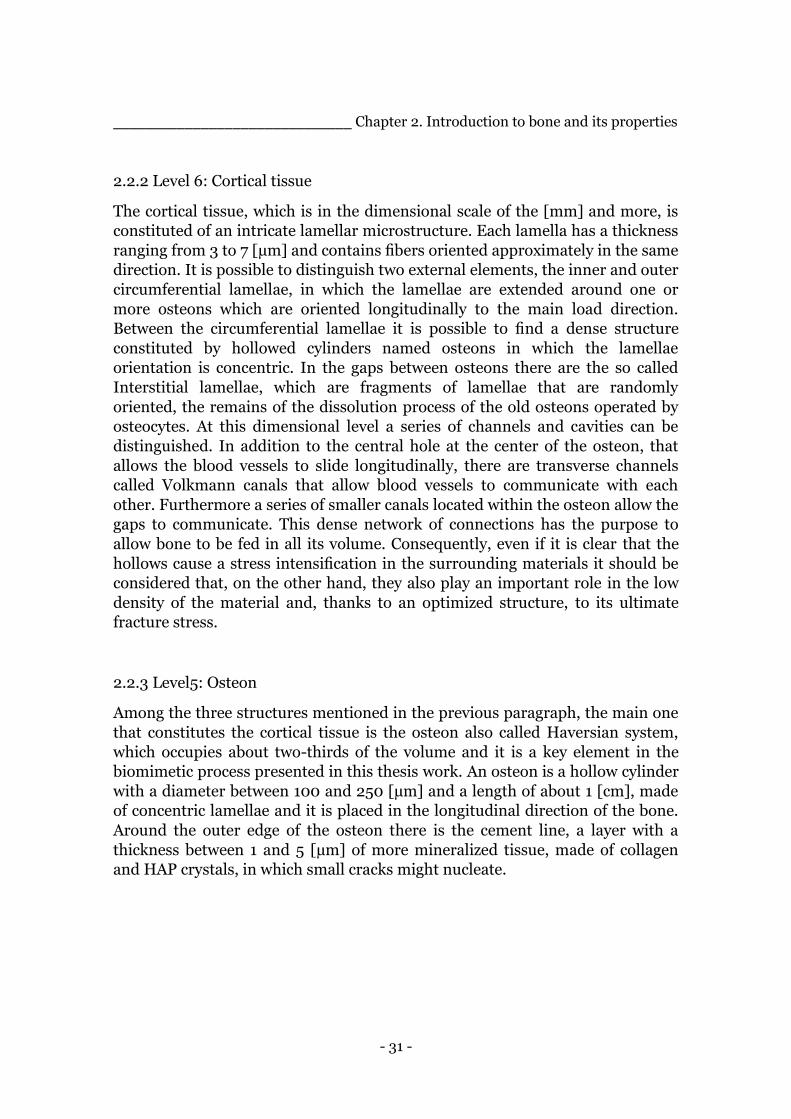
Fig. 2.4. Representation of the osteons and the lamellae that constitute it .................... 33
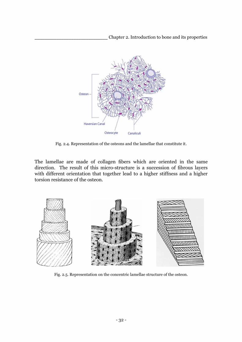
Fig. 2.5. Representation on the concentric lamellae structure of the osteon .................. 33
Fig. 3.1. Bicycle frame in metal and composite material .................................................39
Fig. 3.2. Different types of fibre reinforcement on orientations .................................... 40
Fig. 3.3. Different forms of glass fibre available in the market ....................................... 41
Fig 3.4. Examples of carbon fibres, fabric and rods of bundles ..................................... 42
Fig.3.5. Examples of Aramid Fibres ................................................................................43
Fig. 3.6. Examples of natural fibres ................................................................................ 44
Fig. 3.7. Representation of the filament winding process [19] ....................................... 47
Fig. 3.8. Representation of the pultrusion process [19] ................................................ 48
Fig. 3.9. Elements in a car proposed constituted of natural fibre reinforced composite
materials ......................................................................................................................... 50
Fig. 3.10 Picture of the Lotus “Eco Elise” ...................................................................... 51
Fig. 3.11. Lamborghini “Sesto Senso” ............................................................................. 51
Fig. 4.1. Solid work representation of the set up’s components ...................................... 53
Fig. 4.2. Solid work representation of the set up for the first attempt in the production.
The three disks at each side of the tube will be called throughout the chapter, starting
from the left, outer, middle and inner disk ..................................................................... 54
Fig. 4.3. Photo of the production in progress of the tube before applying the torque at
the two most external disks ............................................................................................. 55
Fig. 4.4. Appearance of the semi-result of production after the second step ................. 56
Fig. 4.5. First tube produced with the ancestor of the ”squeeze winding” process ......... 57
Fig. 4.6. Some details of the adjustments made for the second attempt ....................... 58
Fig. 4.7. Set-up of the second attempt for the production of the tube, everything ready
for the impregnation of the fibres .................................................................................. 59
Fig. 4.8. Result of the second attempt ............................................................................. 61
Fig. 4.9. Picture of the modified inner and middle disks ............................................... 62
Fig. 4.10. External wooden ring ......................................................................................63

- 7 -
Fig. 4.11. Pictures representing the middle layer (above) and the external layer (under)
according to the modifications of the third attempt ...................................................... 64
Fig. 4.12 Picture representing the three tubes made with the final manufacturing
process developed called “squeeze-winding” ................................................................ 66
Fig. 5.1.Mixture of epoxy resin and hardener and a jute thread .................................... 68
Fig. 5.2. Result of the first attempt in making a 0° fibres tube with filament winding
technique .........................................................................................................................70
Fig. 5.3. Result of the second attempt in making a tube with the filament winding
technique ......................................................................................................................... 71
Fig. 5.4. Representation of the different stages of the placing of the fibres in the
filament winding technique ............................................................................................. 72
Fig. 5.5. Result of the third attempt in making a tube with the filament winding process
......................................................................................................................................... 72
Fig. 5.6. Some specimens from the natural fibre tube with the red label ....................... 74
Fig. 5.7. Graphic representation of the stress-strain curve of the samples of the “red”
tube .................................................................................................................................. 75
Fig. 5.8. Graphic representation of the stress-strain curve of the samples of the
“winding” tube ................................................................................................................. 75
Fig. 5.9 Example of a sample after the compression test ................................................ 77
Fig. 5.10. Optic microscope picture and the elaborated image with GIMP .................... 78
Fig. 5.11. Example of picture analysed with the grid method .......................................... 79
Fig. 5.12. Optic microscope picture of a natural fibre sample. ............................................... 81
Fig. 6.1. Representation of the bioinspired laminate produced by previous research
works [15] ...................................................................................................................... 83
Fig. 6.2. Drawing of the design of a part of the section of the bioinspired tube to produce with
indicated all the reinforcement components listed below. ..................................................... 84
Fig. 6.3. Osteonic fibre: the rowing of Glass Fibre and the sleeve of Twill 2x2 Carbon
Fibre[15] ......................................................................................................................... 85
Fig. 6.4. Representation of Twill 2x2 Glass Fibre Woven, on the left, and Unidirectional
Glass Fibre Woven of the right ....................................................................................... 86
Fig. 6.5. Pins placed on the plugs to hold the osteonic fibres at 0° ................................. 87
- 8 -
Fig. 6.6. The osteonic fibres alternating up and down the glass fibre fabric ................. 88
Fig. 6.7. Portion of the section of the first bioinspired composite tube ......................... 89
Fig. 6.8. Portion of the section of the first comparative tube produced ........................ 90
Fig. 6.9. Picture of the two types of tube produced, the bioinspired on the left and the
comparative of the right .................................................................................................. 91
Fig. 6.10. Picture of the tube composed only of osteonic fibres ..................................... 92
Fig. 7.1. Representation of the specimens, one for each type of tube respectively,
bioinspired, comparative and bioinspired without fabric .............................................. 94
Fig. 7.2 Stress-Strain Curve of the specimens from the first Bioinspired tube ............... 95
Fig. 7.3 Stress-Strain Curve of the specimens from the second Bioinspired tube .......... 95
Fig. 7.4 Stress-Strain Curve of the specimens from the first Comparative tube ............ 96
Fig. 7.5 Stress-Strain Curve of the specimens from the second Comparative tube ....... 96
Fig. 7.6. Stress-Strain Curve of the specimens from the Bioinspired without fabric tube.
......................................................................................................................................... 97
Fig. 7.7. Some of the specimens after the compression test ........................................... 98
Fig. 7.8. Optic microscopic picture of glass fibres and the B&W equivalent within a
sample of the produced tube .......................................................................................... 99
Fig. 7.9. Optic microscopic picture of carbon fibres and the B&W equivalent within a
sample of the produced tube .........................................................................................100
Fig. 7.10. Representation of an optic microscopic picture of a sample taken from the
bioinspired without fabric tube, a B&W picture with carbon fibre in black and a B&W
picture with glass fibre in black ..................................................................................... 101
Fig. 8.1. A comparison between a representation of the osteonic structure of cortical
bone and the internal arrangement of fibre in the produced tube ................................ 104
- 9 -
Index of Tables _______________________________________________________________________
_______________________________________________________________________
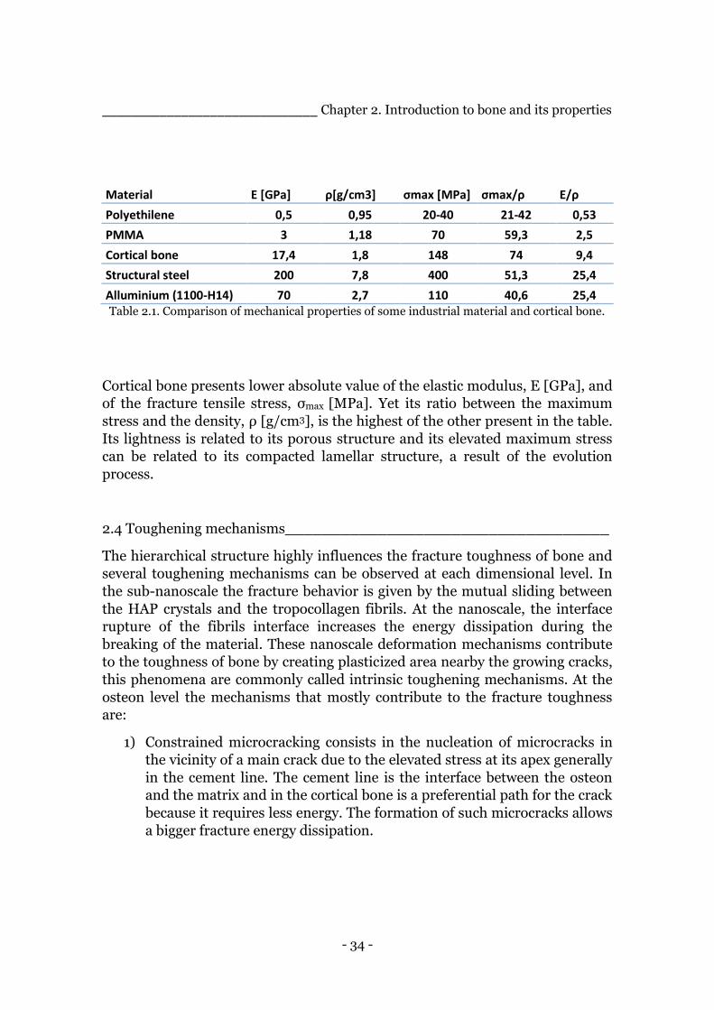
Table 2.1. Comparison of mechanical properties of some industrial material and cortical
bone. ...............................................................................................................................34
Table 5.1. List of components .......................................................................................... 67
Table 5.2. Times associated to the different production phases .................................... 68
Table 5.3. Average values of the mechanical behaviour of the material of the natural
fibre tubes ........................................................................................................................ 75
Table 5.4. Presentation of the data obtained in the two methods of the fibre volume
content ............................................................................................................................. 79
Table 6.1. Characteristics of the reinforcement components ......................................... 85
Table 6.2 Schematic summary of the comparative structure components .................... 88
Table 7.1. Summary of the Compression Properties associated to the materials
composing the produced tubes ........................................................................................ 97
Table 7.2 Summary of the values of fibre volume content obtained for the produced
tubes .............................................................................................................................. 101
- 10 -
Abstract _______________________________________________________________________
_______________________________________________________________________
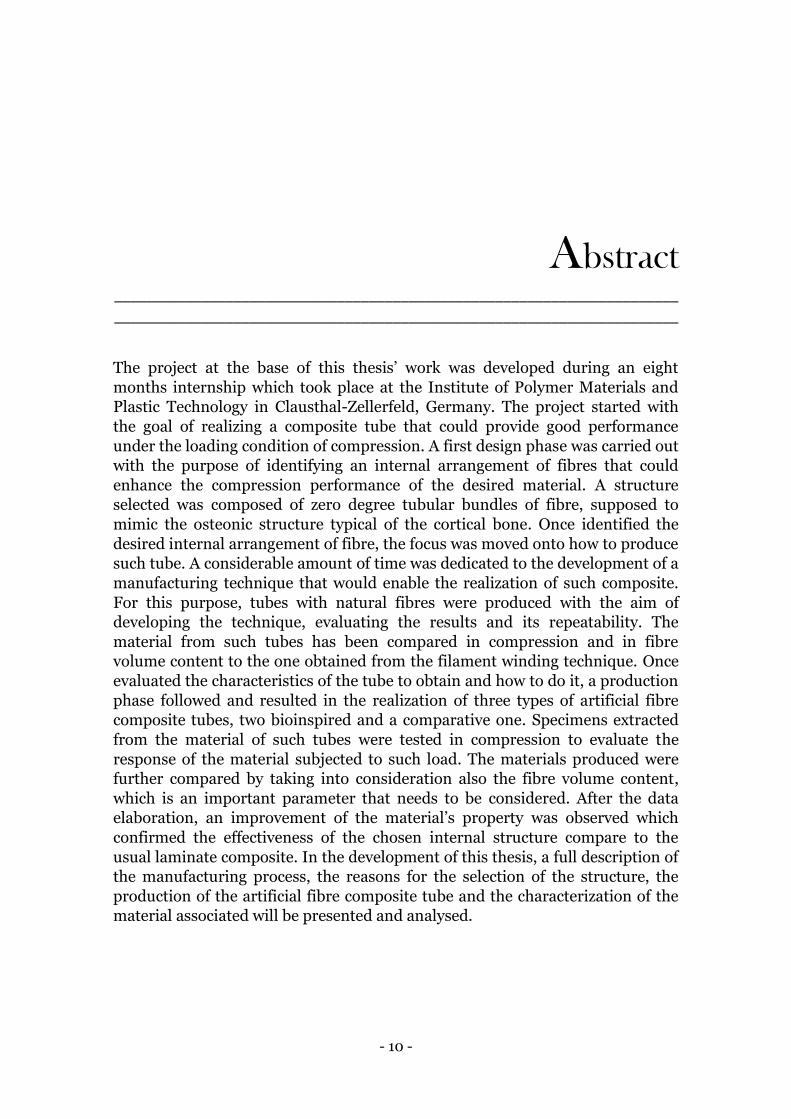
The project at the base of this thesis’ work was developed during an eight
months internship which took place at the Institute of Polymer Materials and
Plastic Technology in Clausthal-Zellerfeld, Germany. The project started with
the goal of realizing a composite tube that could provide good performance
under the loading condition of compression. A first design phase was carried out
with the purpose of identifying an internal arrangement of fibres that could
enhance the compression performance of the desired material. A structure
selected was composed of zero degree tubular bundles of fibre, supposed to
mimic the osteonic structure typical of the cortical bone. Once identified the
desired internal arrangement of fibre, the focus was moved onto how to produce
such tube. A considerable amount of time was dedicated to the development of a
manufacturing technique that would enable the realization of such composite.
For this purpose, tubes with natural fibres were produced with the aim of
developing the technique, evaluating the results and its repeatability. The
material from such tubes has been compared in compression and in fibre
volume content to the one obtained from the filament winding technique. Once
evaluated the characteristics of the tube to obtain and how to do it, a production
phase followed and resulted in the realization of three types of artificial fibre
composite tubes, two bioinspired and a comparative one. Specimens extracted
from the material of such tubes were tested in compression to evaluate the
response of the material subjected to such load. The materials produced were
further compared by taking into consideration also the fibre volume content,
which is an important parameter that needs to be considered. After the data
elaboration, an improvement of the material’s property was observed which
confirmed the effectiveness of the chosen internal structure compare to the
usual laminate composite. In the development of this thesis, a full description of
the manufacturing process, the reasons for the selection of the structure, the
production of the artificial fibre composite tube and the characterization of the
material associated will be presented and analysed.
- 11 -
Sommario _______________________________________________________________________
_______________________________________________________________________
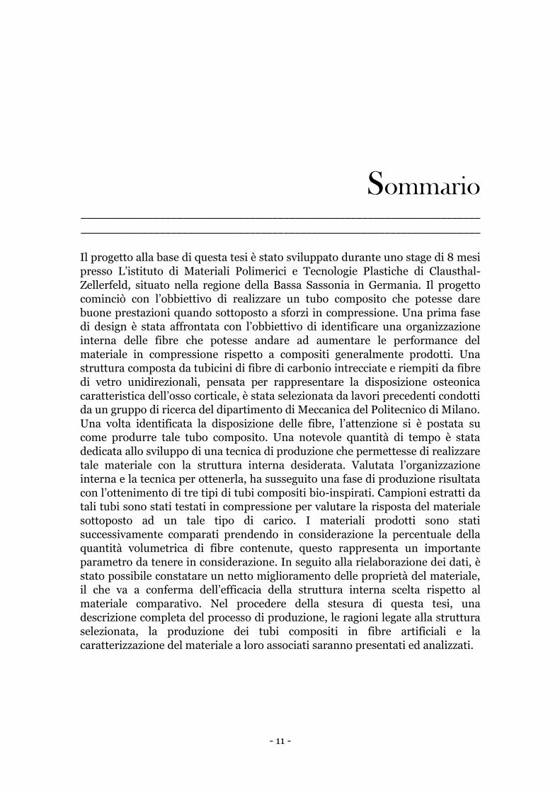
Il progetto alla base di questa tesi è stato sviluppato durante uno stage di 8 mesi
presso L’istituto di Materiali Polimerici e Tecnologie Plastiche di Clausthal-
Zellerfeld, situato nella regione della Bassa Sassonia in Germania. Il progetto
cominciò con l’obbiettivo di realizzare un tubo composito che potesse dare
buone prestazioni quando sottoposto a sforzi in compressione. Una prima fase
di design è stata affrontata con l’obbiettivo di identificare una organizzazione
interna delle fibre che potesse andare ad aumentare le performance del
materiale in compressione rispetto a compositi generalmente prodotti. Una
struttura composta da tubicini di fibre di carbonio intrecciate e riempiti da fibre
di vetro unidirezionali, pensata per rappresentare la disposizione osteonica
caratteristica dell’osso corticale, è stata selezionata da lavori precedenti condotti
da un gruppo di ricerca del dipartimento di Meccanica del Politecnico di Milano.
Una volta identificata la disposizione delle fibre, l’attenzione si è postata su
come produrre tale tubo composito. Una notevole quantità di tempo è stata
dedicata allo sviluppo di una tecnica di produzione che permettesse di realizzare
tale materiale con la struttura interna desiderata. Valutata l’organizzazione
interna e la tecnica per ottenerla, ha susseguito una fase di produzione risultata
con l’ottenimento di tre tipi di tubi compositi bio-inspirati. Campioni estratti da
tali tubi sono stati testati in compressione per valutare la risposta del materiale
sottoposto ad un tale tipo di carico. I materiali prodotti sono stati
successivamente comparati prendendo in considerazione la percentuale della
quantità volumetrica di fibre contenute, questo rappresenta un importante
parametro da tenere in considerazione. In seguito alla rielaborazione dei dati, è
stato possibile constatare un netto miglioramento delle proprietà del materiale,
il che va a conferma dell’efficacia della struttura interna scelta rispetto al
materiale comparativo. Nel procedere della stesura di questa tesi, una
descrizione completa del processo di produzione, le ragioni legate alla struttura
selezionata, la produzione dei tubi compositi in fibre artificiali e la
caratterizzazione del materiale a loro associati saranno presentati ed analizzati.
- 12 -
Chapter 1.
Introduction to Biomimetics _______________________________________________________________________
_______________________________________________________________________
To quote with the words of Janine Benyus , a pioneer of the field, “Biomimetics
is innovation inspired by nature”. Within this simple phrase lays the concept
behind this approach to science and research, which consists in taking
inspiration from a deep understanding of materials and functions found in
nature with the aim of solving engineering problems and provide smart,
innovative and sometimes unexpected solutions.
The word itself, Biomimetics or Biomimicry, is composed of two parts, which
derive from ancient Greek, “bios”, which means life and “mimesis”, which
means imitation.
Even though the interest that this approach has drawn from the scientific
community is rather new, few decades, as it is its efforts to develop a more
systematic translation of concepts from the biological to the technical world, its
roots grow deep into history and several examples of mankind looking up to
nature, both as a simple admiration of it, the story of Icarus and his wax wings
in the Greek mythology, or as a tangible pursuit to reproduce its products, the
attempt of the Chinese to make artificial silk 3000 years ago, can be found.
Coming back to more recent times, the term Biomimetics was coined in the 50s
by Otto Schmitt and other denominations such as “bionics” “biophysics”
“biologically inspired design” were used by many to describe essentially the
same interdisciplinary path to the development of new ideas. The importance of
a multidisciplinary team or the interaction between different scientific figures
such as chemists, biologists, designers, physicists, material scientists and
engineers is vital because it is thanks to the synergy of different skills that a
complete understanding of a biological element, the extraction of its concepts
and their application to a technological problem is possible.

- 13 -
______________________________________ Chapter 1. Introduction to Biomimetics
Nature had 3.8 billions of years to develop itself so it is highly probable that the
solutions it managed to find through evolution represent a good optimization to
the problems it had to face in creating such complex and multifunctional
structures. This way of thinking represents for us an opportunity, to learn from
a more experienced teacher, and a challenge, to extract and use such relations
between function and structure. The power of this approach is also its
versatility, inspiration and insight might be acquired for several fields of
research like architecture and design, lightweight construction and materials,
surface and interfaces, fluid dynamics, robotics, communication etc. Studying a
particular object from nature, also if it doesn’t have a straightforward
connection to the function, might shed some lights on the function that needs to
be unraveled in order to provide a technical answer. In figure 1.1, it is possible to
find some examples of objects from nature and their selected functions [3].
Fig. 1.1. An overview of various objects from nature and their selected functions.
- 14 -
______________________________________ Chapter 1. Introduction to Biomimetics
1.1 Natural and man-made materials______________________________
Natural materials are composed of relatively few constituents which are used to
synthesize a variety of polymers and minerals. On the other hand, man-made
materials are characterized by the use of many more elements. This is
underlined by the invention of materials with special properties, which are not
used by nature, such as copper, iron, in their metallic forms and silicon
semiconductors, distinctive of this information age. These types of materials
require high temperature for fabrication and such energy is not available to
biological systems, yet nature has developed a range of materials with
remarkable functional properties. The choice of elements and the way materials
are made are just two of many differences present between natural and artificial
materials. However, the driver for change in biology and engineering may well
be the same: resolution of a technical conflict [4].
1.1.1 Growth and functional adaptation
An engineer selects a material to fabricate a part according to an exact desired
design, nature goes the opposite way and grows both the material and the whole
organism using the principle of biologically controlled self-assembly. Growth is
a process that can be influenced by external conditions including temperature,
mechanical loading, supply of light, water or nutrition. A living organism must
necessarily possess the ability to adapt to external needs while possible external
influences on a technical system must be typically anticipated in its design
phase. Therefore natural and artificial structures present different strategies in
designing a material: “growth” and “fabrication”. In the case of engineering
materials, the strategy is static as the choice is made at the beginning, according
to the functional requirements and corrosive or deteriorating conditions, also
taking into account possible changes during the service life. The fact that the
natural material grows rather than being fabricated leads to the possibility of a
dynamic strategy [6]. It is not the exact design of the organ that is stored in the
genes but rather an algorithm to build it, the final product is therefore a result
both of such recipe and the several external conditions. The advantage of this
approach is that it allows flexibility at all levels:
1) It permits adaptation to the function while the body is still growing.
2) Allows the growth of hierarchical materials where the microstructure at
each position of the part is adapted to the local needs.
Shape and microstructure become intimately related due to their common
origin which is the growth of the organ. A simple example of this concept is the

- 15 -
______________________________________ Chapter 1. Introduction to Biomimetics
change of shape of a tree due to a landslide or other external events, see figure
1.2.
Fig. 1.2. Adapting abilities of trees to external causes like man or nature.
1.1.2 Hierarchical structuring
Hierarchical structuring is one of the consequences of the growth process of the
organs [6], it allows
1) the construction of large and complex organs based on much smaller
building blocks
2) the adaptation and optimization of the material at each level of hierarchy
to yield outstanding performances.
There are many biological materials that can provide such a complex structure
and present high performance functions. An idea of how wide this reality can be,
it is given by the following examples taken from the natural world: bone, trees,
spider silk, attachment systems of geckos, optical microstructures, skeleton of
glass sponges, super hydrophobic surfaces etc. New functions may be obtained
just by structuring a given material instead of choosing a new one to provide
- 16 -
______________________________________ Chapter 1. Introduction to Biomimetics
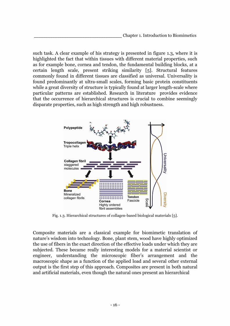
such task. A clear example of his strategy is presented in figure 1.3, where it is
highlighted the fact that within tissues with different material properties, such
as for example bone, cornea and tendon, the fundamental building blocks, at a
certain length scale, present striking similarity [5]. Structural features
commonly found in different tissues are classified as universal. Universality is
found predominantly at ultra-small scales, forming basic protein constituents
while a great diversity of structure is typically found at larger length-scale where
particular patterns are established. Research in literature provides evidence
that the occurrence of hierarchical structures is crucial to combine seemingly
disparate properties, such as high strength and high robustness.
Fig. 1.3. Hierarchical structures of collagen-based biological materials [5].
Composite materials are a classical example for biomimetic translation of
nature’s wisdom into technology. Bone, plant stem, wood have highly optimized
the use of fibers in the exact direction of the effective loads under which they are
subjected. These became really interesting models for a material scientist or
engineer, understanding the microscopic fiber’s arrangement and the
macroscopic shape as a function of the applied load and several other external
output is the first step of this approach. Composites are present in both natural
and artificial materials, even though the natural ones present an hierarchical
- 17 -
______________________________________ Chapter 1. Introduction to Biomimetics
structure that is much more complex and at several scale levels, for man-made
composite it is possible to obtain an hierarchical structure just on few levels.
1.1.3 Damage repair and healing
One of the most remarkable properties of biological materials is their capacity to
self-repair. Even though this property has not yet been transferred to artificial
materials, it represent a very interesting next step for the material engineering
field that it is worth mentioning. There are different strategies associated with
self-repair. At the microscale there is the concept of sacrificial bonds between
molecules that break and reform dynamically, providing the possibility of plastic
deformation. At higher levels many organisms have the possibility to remodel,
for example in bone there are specialized cells that permanently remove
material while others are depositing new tissues [6]. This cyclic replacement of
bone material has a double advantage:
1) It allows a continuous structural adaptation to changing external
conditions
2) It permits the replacement of damaged material wherever and whenever
needed.
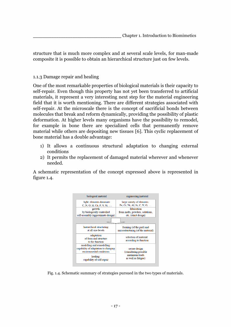
A schematic representation of the concept expressed above is represented in
figure 1.4.
Fig. 1.4. Schematic summary of strategies pursued in the two types of materials.
- 18 -
______________________________________ Chapter 1. Introduction to Biomimetics
1.2 Remarkable features of natural composite materials________________
There are endless examples in nature of composite materials starting from bone,
shells, wood etc., nature tried for millions of years the vast possibilities of the
structural design space and it is reasonable to believe that the structures they
present now are the best answers nature found so far to fulfil some specific
needs. An important aspect of such materials is the remarkable enhancement of
their mechanical properties, compared to the ones of its constituents, that can
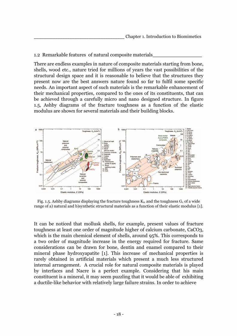
be achieved through a carefully micro and nano designed structure. In figure
1.5, Ashby diagrams of the fracture toughness as a function of the elastic
modulus are shown for several materials and their building blocks.
Fig. 1.5. Ashby diagrams displaying the fracture toughness Kic and the toughness Gc of a wide
range of a) natural and b)synthetic structural materials as a function of their elastic modulus [1].
It can be noticed that mollusk shells, for example, present values of fracture
toughness at least one order of magnitude higher of calcium carbonate, CaCO3,
which is the main chemical element of shells, around 95%. This corresponds to
a two order of magnitude increase in the energy required for fracture. Same
considerations can be drawn for bone, dentin and enamel compared to their
mineral phase hydroxyapatite [1]. This increase of mechanical properties is
rarely obtained in artificial materials which present a much less structured
internal arrangement. A crucial role for natural composite materials is played
by interfaces and Nacre is a perfect example. Considering that his main
constituent is a mineral, it may seem puzzling that it would be able of exhibiting
a ductile-like behavior with relatively large failure strains. In order to achieve
- 19 -
______________________________________ Chapter 1. Introduction to Biomimetics
such performance some requirements must be met [5]:
1) the interface must be weaker than the tablets, the mineral building
blocks, otherwise they would fail in tension before any significant strain,
showing a brittle behavior.
2) Some hardening mechanism must take place at the tablets’ level in order
to spread sliding through the material so the tablets have to climb
obstacles to move on one another.
This clarifies that the performance of nacre is partly controlled by mechanisms
at the interface between the tablets and, generally speaking, the importance of
such interface mechanisms for composite materials.
Natural materials can tune their properties thanks to several structural
parameters such as the geometry of the building blocks, their spatial and
orientational distribution, type and distribution of chemical bonds, their 3D
architecture. Furthermore they seem to be characterized by a multifunctional
behavior, providing sometimes optical, magnetic, sensing and interfacial
properties. The realization of outperforming advanced synthetic materials is
conceivable if the elaborate structures of biological materials are combined with
superior basic constituents. A deep understanding of the design principles
utilized by nature to fulfill the mechanical demands and respond to the dynamic
stimuli of the natural environment might help us address to current limitations
of man-made composites and shed light to pathways to high performance
bioinspired composites.
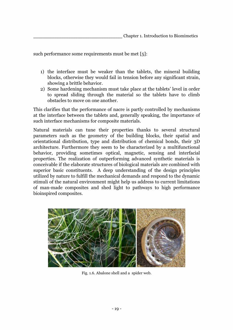
Fig. 1.6. Abalone shell and a spider web.
- 20 -
______________________________________ Chapter 1. Introduction to Biomimetics
1.2.1 Examples
After presenting the main features that characterize materials grown by nature,
it could be interesting to suggest a couple of examples, figure 1.6.
Seashells are composite material constituted mainly of inorganic minerals and a
small fraction of biopolymers. The most studied is the Abalone shell which
presents extraordinary mechanical properties, compared to the main
constituent CaCO3, thanks to his hierarchically organized structure.
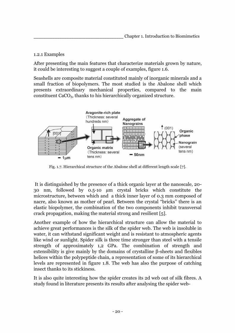
Fig. 1.7. Hierarchical structure of the Abalone shell at different length scale [7].
It is distinguished by the presence of a thick organic layer at the nanoscale, 20-
30 nm, followed by 0.5-10 µm crystal bricks which constitute the
microstructure, between which and a thick inner layer of 0.3 mm composed of
nacre, also known as mother of pearl. Between the crystal “bricks” there is an
elastic biopolymer, the combination of the two components inhibit transversal
crack propagation, making the material strong and resilient [5].
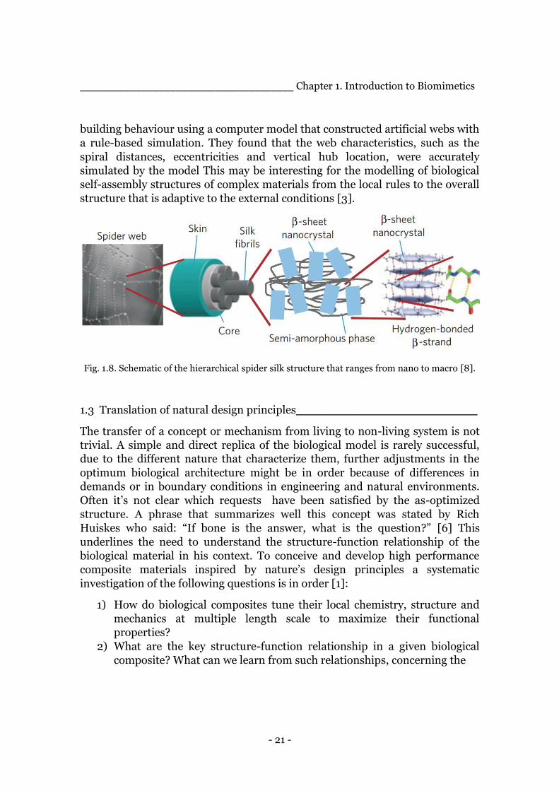
Another example of how the hierarchical structure can allow the material to
achieve great performances is the silk of the spider web. The web is insoluble in
water, it can withstand significant weight and is resistant to atmospheric agents
like wind or sunlight. Spider silk is three time stronger than steel with a tensile
strength of approximately 1,2 GPa. The combination of strength and
extensibility is give mainly by the domains of crystalline β-sheets and flexibles
helices within the polypeptide chain, a representation of some of its hierarchical
levels are represented in figure 1.8. The web has also the purpose of catching
insect thanks to its stickiness.
It is also quite interesting how the spider creates its 2d web out of silk fibres. A
study found in literature presents its results after analysing the spider web-
- 21 -
______________________________________ Chapter 1. Introduction to Biomimetics
building behaviour using a computer model that constructed artificial webs with
a rule-based simulation. They found that the web characteristics, such as the
spiral distances, eccentricities and vertical hub location, were accurately
simulated by the model This may be interesting for the modelling of biological
self-assembly structures of complex materials from the local rules to the overall
structure that is adaptive to the external conditions [3].
Fig. 1.8. Schematic of the hierarchical spider silk structure that ranges from nano to macro [8].
1.3 Translation of natural design principles_________________________
The transfer of a concept or mechanism from living to non-living system is not
trivial. A simple and direct replica of the biological model is rarely successful,
due to the different nature that characterize them, further adjustments in the
optimum biological architecture might be in order because of differences in
demands or in boundary conditions in engineering and natural environments.
Often it’s not clear which requests have been satisfied by the as-optimized
structure. A phrase that summarizes well this concept was stated by Rich
Huiskes who said: “If bone is the answer, what is the question?” [6] This
underlines the need to understand the structure-function relationship of the
biological material in his context. To conceive and develop high performance
composite materials inspired by nature’s design principles a systematic
investigation of the following questions is in order [1]:
1) How do biological composites tune their local chemistry, structure and
mechanics at multiple length scale to maximize their functional
properties?
2) What are the key structure-function relationship in a given biological
composite? What can we learn from such relationships, concerning the

- 22 -
______________________________________ Chapter 1. Introduction to Biomimetics
physical and mechanical design principles underlying the optimum
architecture of the natural material?
3) How can we produce artificial composite that incorporate the design
principles of a given biological material?
1.3.1 Approaches
From literature [2], two main approaches of doing biomimetics emerged.
1) Top-down approach in which engineers start with a specific problem, like
optimizing existing products or processes, and search for ways to solve it
with the aid of biologists and their pool of biological knowledge. After
identifying the most promising solutions with eventually additional
structural and functional analysis, the engineer will abstract the concepts
and create a modified and appropriate technical solution.
2) Bottom-up approach in which the whole process is turned on by the
curiosity or interest of the researcher on a specific organisms from which
new principles are discovered, analyzed and finally transferred into
technical solutions.
1.3.2 Tools
Something that might help to ease the identification of certain biological
species as model due to the fulfillment of particular desired functions, is the
establishment of databases where engineers can find the analysis and
explanations of the structure-function relations, after a deep and thorough
understanding of such natural elements by biologists. The research of a
function on such database should provide the engineer or scientist with
potential models and allow such figure to identify the best suited archetype for
the final goal of the project. Another tool that would help making the
biomimetic approach less fortuitous and more systematic is the development of
a logical framework that takes its origin from TRIZ [4]. It was developed in
Russia, more or less 50 years ago, and it is known for its successful transfer of
inventions and solutions from one field of engineering to another. This
peculiarity makes it really appealing to the biomimetic approach which is
basically the transfer of principles and mechanisms from biology to science and
engineering. It consists in an accurate definition of a problem and its context by
the association with a pair of opposing or conflicting characteristics. In order to
standardize the process, many patents were analyzed and a list of 39 conflicting
- 23 -
______________________________________ Chapter 1. Introduction to Biomimetics
characteristics was outlined. To make the process easier such conflicting couples
were placed in a matrix with antithetic features along the top and the desired
features arranged along the vertical axis. Once the “contradiction matrix” is
available, the problem can be solved by separating it from its context so that
solutions to any problems can be drawn from a very wide range of science and
technology. One of the peculiarity of such method is that the more incompatible
the contradiction features are, the stronger the solution will be revealed. The
TRIZ method is rather complex, yet it’s worth mentioning because attempts
towards defining a matrix derived from biological effects have been done and
some results show an analogy of only 12%, between biology and technology, in
the principles which solutions to problems illustrate. While technology solves
problems mainly by manipulating usage of energy, biology uses information and
structure [4]. Such study shows what is the potentiality, yet unexplored, of the
principles on which natural solutions are based.
1.4 Biomimetics in the industry_________________________________
The biomimetic approach has proven itself of being able to help delivering
smart and efficient solutions into the market. It has been estimated that the 100
largest biomimetic products had generated approximately US $1,5 billion over
2005-2008 and the annual sales are expected to continue increasing[3].
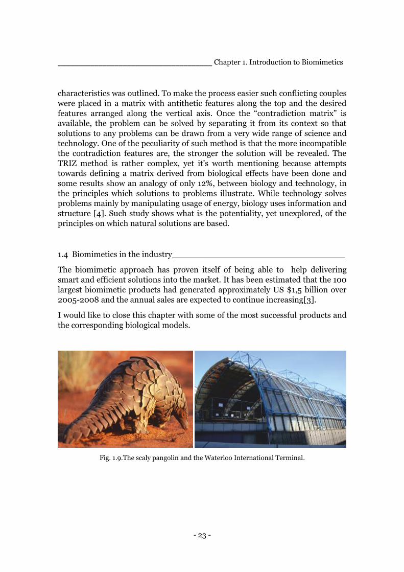
I would like to close this chapter with some of the most successful products and
the corresponding biological models.
Fig. 1.9.The scaly pangolin and the Waterloo International Terminal.
- 24 -
_______________________________________ Chapter 1. Introduction to Biomimetic
The scaly pangolin inspired the design of the Waterloo International Terminal.
The movement of the scales of the pangolin, allow air to circulate, regulating its
temperature. As a result of the design, the layout and movement of the glass
panels allow the surge in air pressure, from trains entering the station, to
efficiently and safely escape, figure 1.9.
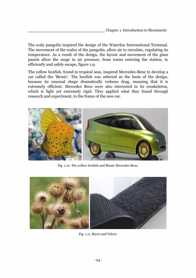
The yellow boxfish, found in tropical seas, inspired Mercedes-Benz to develop a
car called the ‘Bionic’. The boxfish was selected as the basis of the design,
because its unusual shape dramatically reduces drag, meaning that it is
extremely efficient. Mercedes Benz were also interested in its exoskeleton,
which is light yet extremely rigid. They applied what they found through
research and experiment, to the frame of the new car.
Fig. 1.10. The yellow boxfish and Bionic Mercedes Benz.
Fig. 1.11. Burrs and Velcro.
- 25 -
______________________________________ Chapter 1. Introduction to Biomimetics
In 1941 Swiss engineer Georges de Mestral was walking his dog through a field,
when he realised that the dog’s fur and his trousers had numerous burrs
attached to them. Burrs have natural hooks that attach to almost any type of fur
and textiles. He took inspiration from this to invent Velcro, figure 1.11.
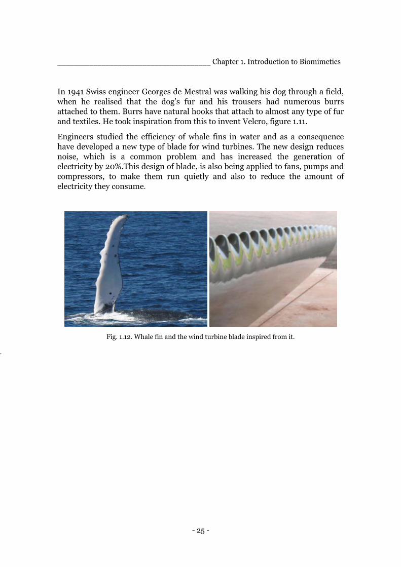
Engineers studied the efficiency of whale fins in water and as a consequence
have developed a new type of blade for wind turbines. The new design reduces
noise, which is a common problem and has increased the generation of
electricity by 20%.This design of blade, is also being applied to fans, pumps and
compressors, to make them run quietly and also to reduce the amount of
electricity they consume.
Fig. 1.12. Whale fin and the wind turbine blade inspired from it.
.
- 26 -
Chapter 2.
Introduction to
Bone and its Properties _______________________________________________________________________
_______________________________________________________________________
The nature-made model chosen for this project as a biomimetic source of
inspiration and wisdom is bone, in particular the cortical one. The reasons for
this choice will become clear through the scrolling of this chapter.
Bone represents one of the most studied biological material both due to the
great efforts of medical research to cure diseases like osteoporosis or to provide
better prosthesis and to the increasing engineering interest to unravel the
concepts behind such a remarkable material.
Bone must satisfy several request to fulfil its tasks, first of all superior
mechanical properties to sustain the whole structure and yet it has to be light to
allow movements without the use of a lot of energy, strength is also important to
avoid breaking after impacts and protect internal organs. Considering that it is a
living material it has to be able of self-healing in case of fracture and
dynamically respond to the internal and external constraints of a growing
structure.
Bone is composed of two main constituents, a collagen matrix which provide
elasticity and the ability of dissipating energy under mechanical deformation
and hydroxyapatite mineral crystals that grant the load bearing capacity and
which occupy more than 60% of the volume. It is possible to find also other
types of substances including inorganic minerals components such as calcium,
phosphorus, magnesium etc. , while among the organic ones it is possible to find
proteoglycans, non-collagenous proteins, cytokines and growth factors.
Particularly interesting are the cells involved in self-healing and repair
- 27 -
______________________________ Chapter 2. Introduction to bone and its properties
such osteoblasts, osteocytes and osteoclasts which continuously regenerate bone
through a process of destruction and reconstruction.
In the last 50 years the scientific community has gained a much deeper
understanding of this tissue and the internal structural reasons of its behavior.
This insight has come mainly from the enabling of technology which has become
able of reaching smaller length scales. Yet I would like to underline that from a
reading of scientific literature it emerged that there is still a lot to uncover in
terms of bone internal structure and its relation to the requirements of its
functions.
2.1 Different types and functions of bones__________________________
An adult human skeleton consists of around 206 different bone with several
shapes and dimensions through which it is possible to classify them:
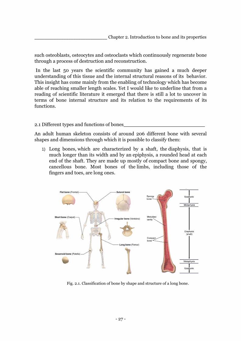
1) Long bones, which are characterized by a shaft, the diaphysis, that is
much longer than its width and by an epiphysis, a rounded head at each
end of the shaft. They are made up mostly of compact bone and spongy,
cancellous bone. Most bones of the limbs, including those of the
fingers and toes, are long ones.
Fig. 2.1. Classification of bone by shape and structure of a long bone.
- 28 -
______________________________ Chapter 2. Introduction to bone and its properties
2) Short bones are roughly cube-shaped and have only a thin layer of
compact bone surrounding a spongy interior. The bones of the wrist and
ankle are short bones.
3) Flat bones are thin and generally curved, with two parallel layers of
compact bones sandwiching a layer of spongy bone. Most of the bones of
the skull are flat bones.
4) Sesamoid bones are bones embedded in tendons. Since they act to hold
the tendon further away from the joint, the angle of the tendon is
increased and thus the leverage of the muscle is increased.
5) Irregular bones are the ones that do not fit into the above categories.
They consist of thin layers of compact bone surrounding a spongy
interior. Their shapes are irregular and complicated. The bones of
the spine, pelvis and some bones of the skull are examples of this
category.
All these types of bones help the skeleton providing the needed functions which
can be divided mainly in 3 categories:
Mechanical: 1) support of the weight of the whole structure,
2) protection for the organs,
3) facilitation of movements,
4) it facilitates hearing,
Synthetic: 5) it contains bone marrow,
Metabolic: 6) it stores calcium,
7) it helps regulate the acid-base balance.
To think that just one material is able to provide all of these functions is
absolutely remarkable. The question is “How does it do it?”. The answer may
take a first step from the considerations made in the previous chapter about a
characteristic of biological materials, their hierarchical internal structure.
- 29 -
______________________________ Chapter 2. Introduction to bone and its properties
2.2 Hierarchical structure_____________________________________
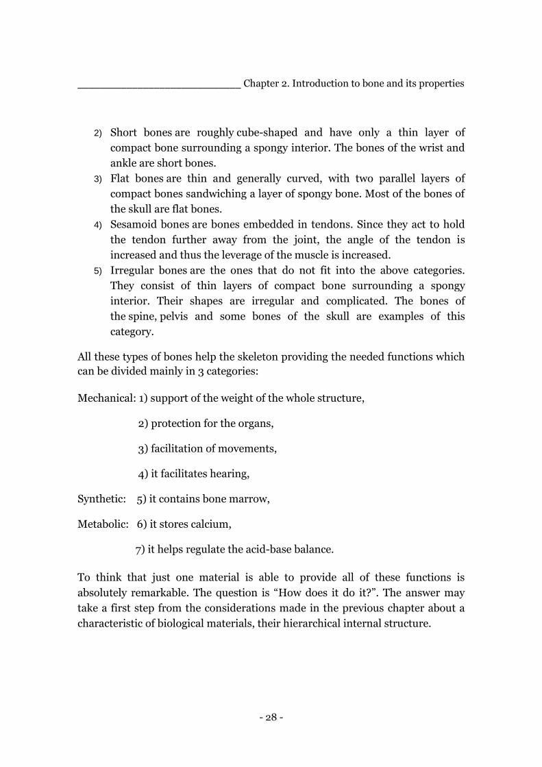
As observed in the majority of natural tissues, bone also is characterized by a
complex hierarchical structure that allows the differentiation of many bone
tissues and not only, starting from common building blocks arranged in
particular ways. One of the results of nature’s efforts is an increase of the
mechanical properties of the resulting tissues compared to the ones of the single
building blocks. In the following picture it’s possible to have an idea of how
articulate the structure is and the main mechanisms for mechanical toughening
at each dimensional level presented.
Fig. 2.2. Graphic representation of the hierarchical structure in bone [5].
- 30 -
______________________________ Chapter 2. Introduction to bone and its properties
A brief description of the several levels found in bone will be presented in the
following paragraphs, but before , I would like recall a consideration proposed
by John D. Curry according to whom the number of levels to consider is not
fixed but it is dependent on the user and in particular to his specific interest and
his availability of equipment [12].
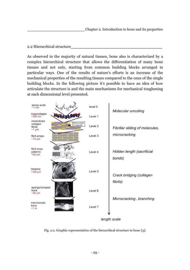
2.2.1 Level 7: Macro-structure
Bone can be distinguished in cortical tissue, also known as compact bone, or in
trabecular tissue, also known as spongy or cancellous. By taking into account
long bones, such as the humerus, femur and tibia, it is possible to find both
macrostructures. A long bone is composed of a central hollow cylindrical
portion called diaphysis mainly composed of cortical tissue, responsible for the
characteristics of stiffness and hardness of bone, and two rounded ends, called
epiphysis, composed of trabecular tissue covered by a thin layer of cortical bone.
The cortical tissue is about 80 % of the skeleton mass and ensure the stiffness
and hardness of bone. The specific part of bone on which this project take is first
steps for the creation of a bioinspired composite material is the cortical tissue,
the following descriptions will focus mainly on this part of the bone structure.
Fig. 2.3. Representation of the cortical and the trabecular bone.
- 31 -
______________________________ Chapter 2. Introduction to bone and its properties
2.2.2 Level 6: Cortical tissue
The cortical tissue, which is in the dimensional scale of the [mm] and more, is
constituted of an intricate lamellar microstructure. Each lamella has a thickness
ranging from 3 to 7 [µm] and contains fibers oriented approximately in the same
direction. It is possible to distinguish two external elements, the inner and outer
circumferential lamellae, in which the lamellae are extended around one or
more osteons which are oriented longitudinally to the main load direction.
Between the circumferential lamellae it is possible to find a dense structure
constituted by hollowed cylinders named osteons in which the lamellae
orientation is concentric. In the gaps between osteons there are the so called
Interstitial lamellae, which are fragments of lamellae that are randomly
oriented, the remains of the dissolution process of the old osteons operated by
osteocytes. At this dimensional level a series of channels and cavities can be
distinguished. In addition to the central hole at the center of the osteon, that
allows the blood vessels to slide longitudinally, there are transverse channels
called Volkmann canals that allow blood vessels to communicate with each
other. Furthermore a series of smaller canals located within the osteon allow the
gaps to communicate. This dense network of connections has the purpose to
allow bone to be fed in all its volume. Consequently, even if it is clear that the
hollows cause a stress intensification in the surrounding materials it should be
considered that, on the other hand, they also play an important role in the low
density of the material and, thanks to an optimized structure, to its ultimate
fracture stress.
2.2.3 Level5: Osteon
Among the three structures mentioned in the previous paragraph, the main one
that constitutes the cortical tissue is the osteon also called Haversian system,
which occupies about two-thirds of the volume and it is a key element in the
biomimetic process presented in this thesis work. An osteon is a hollow cylinder
with a diameter between 100 and 250 [µm] and a length of about 1 [cm], made
of concentric lamellae and it is placed in the longitudinal direction of the bone.
Around the outer edge of the osteon there is the cement line, a layer with a
thickness between 1 and 5 [µm] of more mineralized tissue, made of collagen
and HAP crystals, in which small cracks might nucleate.
- 32 -
______________________________ Chapter 2. Introduction to bone and its properties
Fig. 2.4. Representation of the osteons and the lamellae that constitute it.
The lamellae are made of collagen fibers which are oriented in the same
direction. The result of this micro-structure is a succession of fibrous layers
with different orientation that together lead to a higher stiffness and a higher
torsion resistance of the osteon.
Fig. 2.5. Representation on the concentric lamellae structure of the osteon.
- 33 -
______________________________ Chapter 2. Introduction to bone and its properties
A study presented in literature demonstrated that a soft osteon promotes micro
cracks propagation towards the osteon whereas hard osteon repel micro cracks.
Considering that cement lines act as an interface for crack propagation, upon
encountering a cement line, a crack would cease to travel transversely and
follow the longitudinal boundary trapping the crack in the cement line,
therefore increasing the fracture toughness of the bone [16].
2.2.4 Smaller Levels: collagen fibers, fibril, tropocollagen and polypeptide chain.
The next hierarchical levels are on the nano-scale. Indeed it was observed that
the collagen fibers are constitute of smaller collagen fibrils all oriented on the
same direction. The diameter of a collagen fiber is around 0.5÷3 [µm], while the
fibrils one is between 10 ÷ 300 [nm]. A fibril could be described as a bundle of
tropocollagen molecules bonded together thanks to hydroxyapatite crystals (10
[nm] thick and 225 [nm] long. The hydroxyapatite is really important for the
resistance and fracture toughness of bone. Deepening further it is possible to
describe a tropocollagen molecules as a triple-helix structure made up of
polypeptide chains linked by hydrogen bonds. The tropocollagen molecules have
a diameter of 2 [nm], while the single polypeptide chain have a diameter of 1
[nm]. By recent studies it is believed that this triple-helix structure could be
related to the elastic properties of the bone tissue, in fact under the influence of
a load the tropocollagen molecules tend to unrolls, leading to large strain,
whereas the hydrogen bonds can be rebuilt, acting as sacrificial bonds. Indeed,
the progressive formation and breakage of such bonds increases the energy to
failure, allowing the preservation of the mechanical properties and the
enhancement of fracture toughness.
2.3 Mechanical Properties of Bone_______________________________
Experimental tests have shown that the mechanical performances of bone,
greatly depend on humidity, age, type of bone, portion of the bone itself,
temperature and load direction. Due to its structure, bone is highly anisotropic
and it is possible to notice that it presents higher elastic properties
longitudinally rather than transversally. In table 2.1 it is possible to find a
comparison between the mechanical properties of bone and those of other
common industrial materials.
- 34 -
______________________________ Chapter 2. Introduction to bone and its properties
Material E [GPa] ρ[g/cm3] σmax [MPa] σmax/ρ E/ρ
Polyethilene 0,5 0,95 20-40 21-42 0,53
PMMA 3 1,18 70 59,3 2,5
Cortical bone 17,4 1,8 148 74 9,4
Structural steel 200 7,8 400 51,3 25,4
Alluminium (1100-H14) 70 2,7 110 40,6 25,4 Table 2.1. Comparison of mechanical properties of some industrial material and cortical bone.
Cortical bone presents lower absolute value of the elastic modulus, E [GPa], and
of the fracture tensile stress, σmax [MPa]. Yet its ratio between the maximum
stress and the density, ρ [g/cm3], is the highest of the other present in the table.
Its lightness is related to its porous structure and its elevated maximum stress
can be related to its compacted lamellar structure, a result of the evolution
process.
2.4 Toughening mechanisms___________________________________
The hierarchical structure highly influences the fracture toughness of bone and
several toughening mechanisms can be observed at each dimensional level. In
the sub-nanoscale the fracture behavior is given by the mutual sliding between
the HAP crystals and the tropocollagen fibrils. At the nanoscale, the interface
rupture of the fibrils interface increases the energy dissipation during the
breaking of the material. These nanoscale deformation mechanisms contribute
to the toughness of bone by creating plasticized area nearby the growing cracks,
this phenomena are commonly called intrinsic toughening mechanisms. At the
osteon level the mechanisms that mostly contribute to the fracture toughness
are:
1) Constrained microcracking consists in the nucleation of microcracks in
the vicinity of a main crack due to the elevated stress at its apex generally
in the cement line. The cement line is the interface between the osteon
and the matrix and in the cortical bone is a preferential path for the crack
because it requires less energy. The formation of such microcracks allows
a bigger fracture energy dissipation.
- 35 -
______________________________ Chapter 2. Introduction to bone and its properties
2) Crack deflection and crack twisting, the difference between the two is
that in the first mechanism the deviation of the crack path occur in plane
while in the second one the deviation leads the crack out of plane. In
cortical bone, since the preferred direction of the crack propagation is
parallel to the osteon due to the presence of the cement line, the best
loading direction is the same one because in his way the load direction
and the crack direction are perpendicular and it is possible to obtain a
higher tenacity.
3) Ligament bridging, the presence of uncracked ligaments inside the path
of a crack lead to a redistribution of the load and an increase in the
fracture energy necessary to the crack to propagate.
Such mechanisms present an interesting example of how bone manages to
provide toughness and resistance to fracture. By recalling the biomimetic
approach to science introduced in the previous chapter, these could lead to the
understanding and the use of nature design principles and it is worth pursuing
if we aim at increasing the fracture toughness of a man made composite
materials. The attempt to reproduce some of the fracture toughening
mechanisms is part of this project and the procedure followed will be explained
in the following chapters.
- 36 -
Chapter 3.
Composite Materials and
Manufacturing Techniques _______________________________________________________________________
_______________________________________________________________________
Fibres-reinforced composite materials are the result of a successful combination
of two main elements, fibres and matrix, which leads to the creation of a new
material with properties that are not obtainable by the single separate units. The
fibres have the purpose of sustaining the loads to which the material is
subjected, for this reason they present high strength and modulus, while the
matrix maintains them into their specific positions, shelters the fibres from
deterioration and allows the transmission of loads. The two elements do not
merge together but preserve their chemical and physical identities, as a
consequence, interfaces between them play an important role in the mechanical
properties of the final material. This field of material engineering is at the basis
of this project work and some of the key elements of such a wide technical
domain will be presented throughout the chapter.
3.1 Characteristics of Composite Materials__________________________
Low density, strength-weight ratio, modulus-weight ratio, fatigue damage
tolerance and fatigue strength are some of the characteristics that allowed fibre
composite material to be used, or investigated for a future use, in the place of
metallic materials for elements that require the lowest possible weight, for
example in the field of aerospace or automotive. Fibres reinforced polymers rise
then as an important class of structural materials.
As opposed to structural metals, such as steel and aluminium alloys, which
display a non-dependence on the direction on which its mechanical properties
are measured, fibre-reinforced composite are considered anisotropic, their
- 37 -
________________Chapter 3. Composite Materials and Manufacturing Techniques
mechanical response is higher if evaluated along the fibre direction.
Multidirectional reinforcement may present a more equitable set of properties
but yet lower than the case of measurements along the direction of
unidirectional fibres. Both cases may represent interesting edges over metallic
materials on a unit weight basis. This peculiarity presents the drawback of
generating more difficulty in the design phase due to the direction relation of
the mechanical properties but it presents also the great possibility of reinforcing
the material in the directions subjected to the highest stresses by means of a
tailor-like design phase.
By observing both metal and composite materials some interesting points can
be highlighted:
1. Most fibre reinforced composites present an elastic behaviour in their
tensile stress-strain curve while metals are characterized by yielding and
plastic deformation. However, due to its heterogeneous structure, some
mechanisms of energy absorption occur at the microscale [17] and,
depending on the type and severity of the external load, catastrophic
failure may be avoided thanks to the occurrence of gradual deterioration.
2. In the efforts of replacing metal components with composite ones, the
different mechanisms of damage development and growth must be
thoroughly taken into account during the design phase.
3. Fibre reinforced polymers present a much lower coefficient of thermal
expansion, if compared to the metal ones.
4. High internal damping is a peculiar characteristic of this kind of material,
it leads to better vibrational absorption within the material itself and has
the outcome of reducing the transmission of noise and vibration to
neighbouring structures. This characteristic is really desirable, for
example, for sport’s gear and automotive applications where a lot of
effort is put in resolving issues for the passenger comfort like noise and
vibrations.
5. Fibre-reinforced polymers may absorb moisture or chemical from the
environment in which they are placed and this could lead to the
development of internal stresses due to dimensional changes. However,
generally speaking, composite materials are known for their non-
corroding behaviour compared to metallic materials.
- 38 -
___________________Chapter 3. Composite Materials and Manufacturing Techniques
6. The composite technology requires less energy and lower pressures for
the production processes in comparison with metallic materials, in
addition it presents advantages in the possibility of reducing the number
of components and hence the number and costs of manufacturing and
assembly operations. Furthermore it leads to the possibility of
eliminating finishing operations like for example grinding.
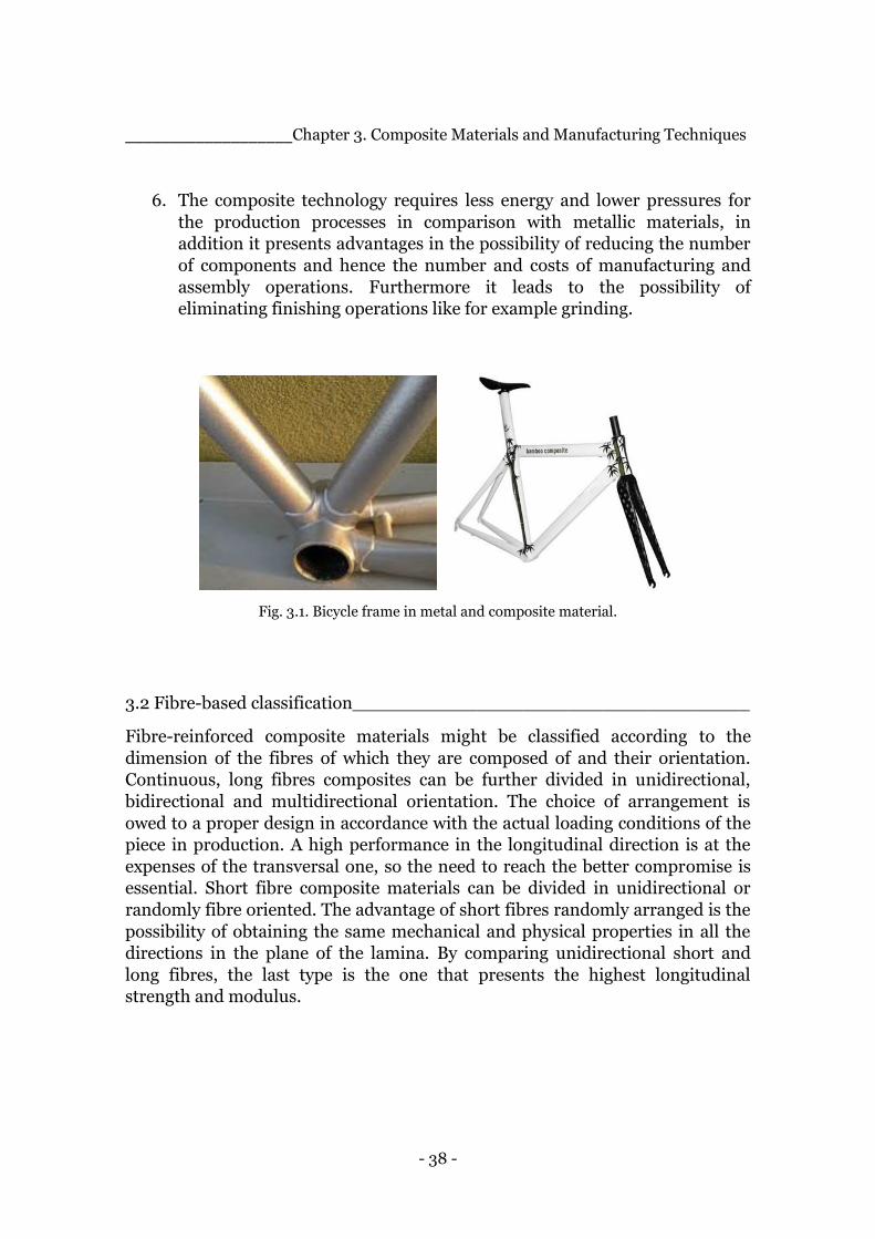
Fig. 3.1. Bicycle frame in metal and composite material.
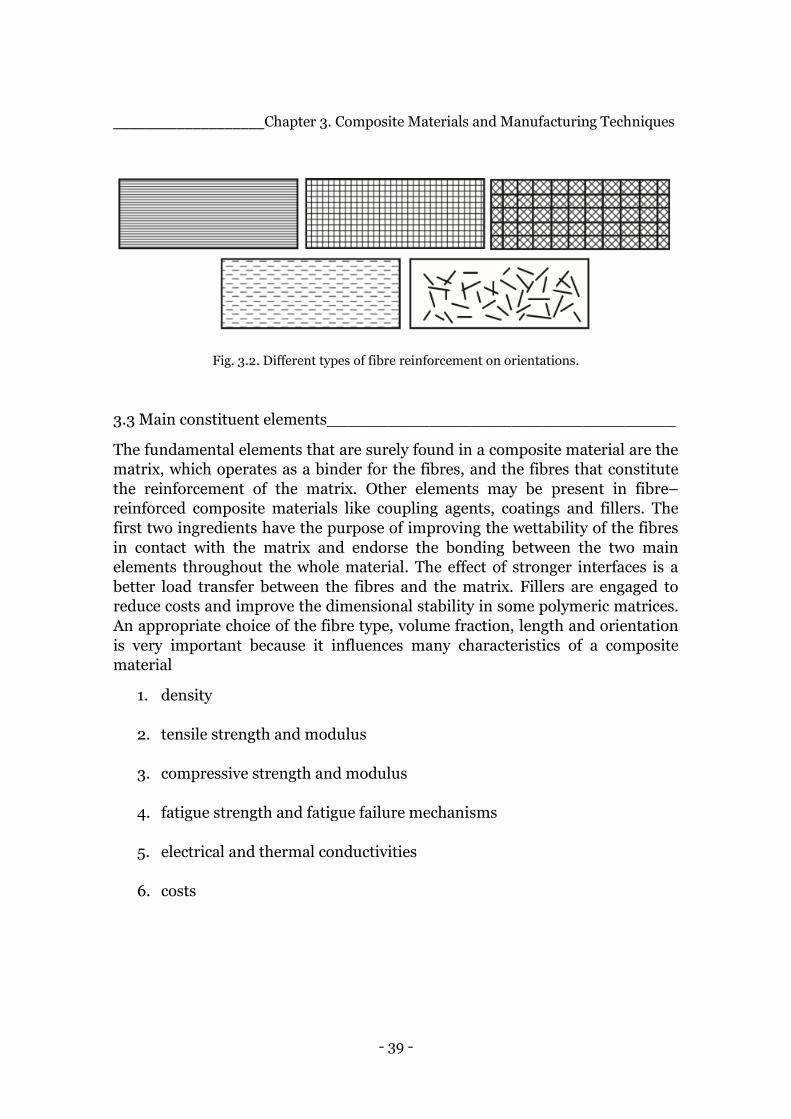
3.2 Fibre-based classification___________________________________
Fibre-reinforced composite materials might be classified according to the
dimension of the fibres of which they are composed of and their orientation.
Continuous, long fibres composites can be further divided in unidirectional,
bidirectional and multidirectional orientation. The choice of arrangement is
owed to a proper design in accordance with the actual loading conditions of the
piece in production. A high performance in the longitudinal direction is at the
expenses of the transversal one, so the need to reach the better compromise is
essential. Short fibre composite materials can be divided in unidirectional or
randomly fibre oriented. The advantage of short fibres randomly arranged is the
possibility of obtaining the same mechanical and physical properties in all the
directions in the plane of the lamina. By comparing unidirectional short and
long fibres, the last type is the one that presents the highest longitudinal
strength and modulus.
- 39 -
___________________Chapter 3. Composite Materials and Manufacturing Techniques
Fig. 3.2. Different types of fibre reinforcement on orientations.
3.3 Main constituent elements__________________________________
The fundamental elements that are surely found in a composite material are the
matrix, which operates as a binder for the fibres, and the fibres that constitute
the reinforcement of the matrix. Other elements may be present in fibre–
reinforced composite materials like coupling agents, coatings and fillers. The
first two ingredients have the purpose of improving the wettability of the fibres
in contact with the matrix and endorse the bonding between the two main
elements throughout the whole material. The effect of stronger interfaces is a
better load transfer between the fibres and the matrix. Fillers are engaged to
reduce costs and improve the dimensional stability in some polymeric matrices.
An appropriate choice of the fibre type, volume fraction, length and orientation
is very important because it influences many characteristics of a composite
material
1. density
2. tensile strength and modulus
3. compressive strength and modulus
4. fatigue strength and fatigue failure mechanisms
5. electrical and thermal conductivities
6. costs

- 40 -
___________________Chapter 3. Composite Materials and Manufacturing Techniques
Fibres present a very small diameter and to ease their handling they are
commercially found in bundles produced by assembling together a large
number of continuous fibres, either in twisted or untwisted form. The almost
linear tensile stress-strain diagram up to the breaking point, the low strain to
failure and the brittle failure mode make the fibres susceptible to damage
during handling or in contact with other surfaces. The high tensile strengths
presented by the reinforcing fibres is generally attributed to their filamentary
form in which there are statistically fewer surface flaws than in the bulk form
[17]. Generally speaking the tensile strength is higher than the compressive one.
3.3.1 Glass fibres
Glass fibres are one of the most used type of reinforcement for a polymeric
material. There are different kinds which differ in the composition and the
manufacturing costs, E-glass and S-glass. There is another type called C-glass
used in case of the need of higher corrosion resistance to acids. Glass fibres
present an amorphous and isotropic structure, a three dimensional internal
architecture constituted of a long network of silicon, oxygen and other atoms
randomly placed. The bundles of untwisted fibres are wound in a cylindrical
package, such roving, is generally used in continuous molding operations, such
as filament winding and pultrusion.
Fig. 3.3. Different forms of glass fibre available in the market.
Some of the advantages are the low costs, a high tensile strength, a high
chemical resistance and excellent insulating properties. On the other hand,
between the disadvantages there are a relatively low tensile modulus and high
density compared to commercial fibres, susceptibility to abrasion during
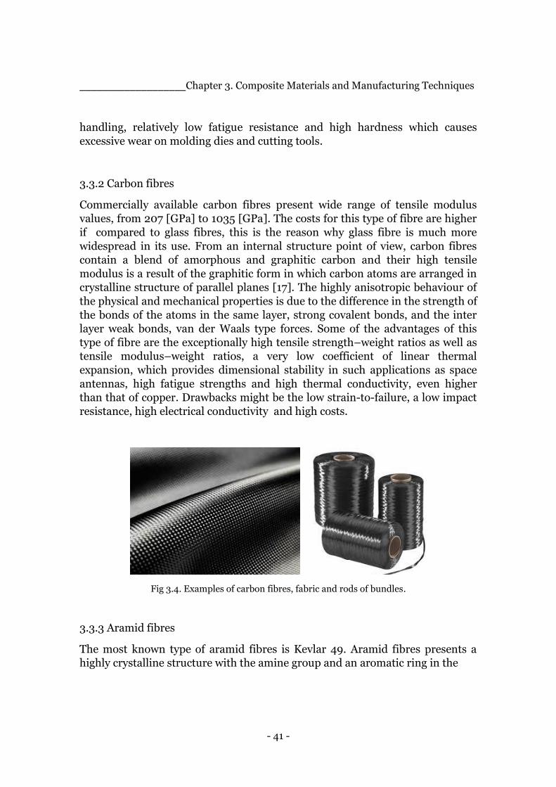
- 41 -
___________________Chapter 3. Composite Materials and Manufacturing Techniques
handling, relatively low fatigue resistance and high hardness which causes
excessive wear on molding dies and cutting tools.
3.3.2 Carbon fibres
Commercially available carbon fibres present wide range of tensile modulus
values, from 207 [GPa] to 1035 [GPa]. The costs for this type of fibre are higher
if compared to glass fibres, this is the reason why glass fibre is much more
widespread in its use. From an internal structure point of view, carbon fibres
contain a blend of amorphous and graphitic carbon and their high tensile
modulus is a result of the graphitic form in which carbon atoms are arranged in
crystalline structure of parallel planes [17]. The highly anisotropic behaviour of
the physical and mechanical properties is due to the difference in the strength of
the bonds of the atoms in the same layer, strong covalent bonds, and the inter
layer weak bonds, van der Waals type forces. Some of the advantages of this
type of fibre are the exceptionally high tensile strength–weight ratios as well as
tensile modulus–weight ratios, a very low coefficient of linear thermal
expansion, which provides dimensional stability in such applications as space
antennas, high fatigue strengths and high thermal conductivity, even higher
than that of copper. Drawbacks might be the low strain-to-failure, a low impact
resistance, high electrical conductivity and high costs.
Fig 3.4. Examples of carbon fibres, fabric and rods of bundles.
3.3.3 Aramid fibres
The most known type of aramid fibres is Kevlar 49. Aramid fibres presents a
highly crystalline structure with the amine group and an aromatic ring in the

- 42 -
___________________Chapter 3. Composite Materials and Manufacturing Techniques
repeating unit which gives a higher chain stiffness and a better mechanical and
thermal stability. Aramid fibres present the highest tensile strength-to-weight
ratio and the lowest density among the present reinforcing fibres, good
resistance to impact damage and a negative coefficient of thermal expansion. As
negative aspects it can be considered the low compressive strength and the
difficulty in cutting or machining.
Fig.3.5. Examples of Aramid Fibres.
3.3.4 Natural Fibres
Examples of natural fibres are jute, flax, hemp, remi, sisal, coconut fibre (coir),
and banana fibre (abaca), they are grown as agricultural plants in various parts
of the world and are commonly used for making ropes, carpet backing, bags,
and so on. They are composed of cellulose micro fibrils dispersed in an
amorphous matrix of lignin and hemicellulose [17], the cellulose ranges from 60
to 80 wt% and the lignin content is in the range of 5–20 wt%, furthermore the
moisture content in natural fibres can be up to 20 wt%.
Natural fibre-reinforced polymers have recently attracted increasing interest
from the industry thanks to some of their peculiar characteristics
1. They are environment-friendly, which means that they are biodegradable
and they require much less energy for their production if compared to
synthetic fibres,
2. Natural fibres’ densities range from 1.25 to 1.5 [g/cm3] compared to 2.54
[g/cm3] for E-glass fibres and 1.8–2.1 [g/cm3] for carbon fibres.
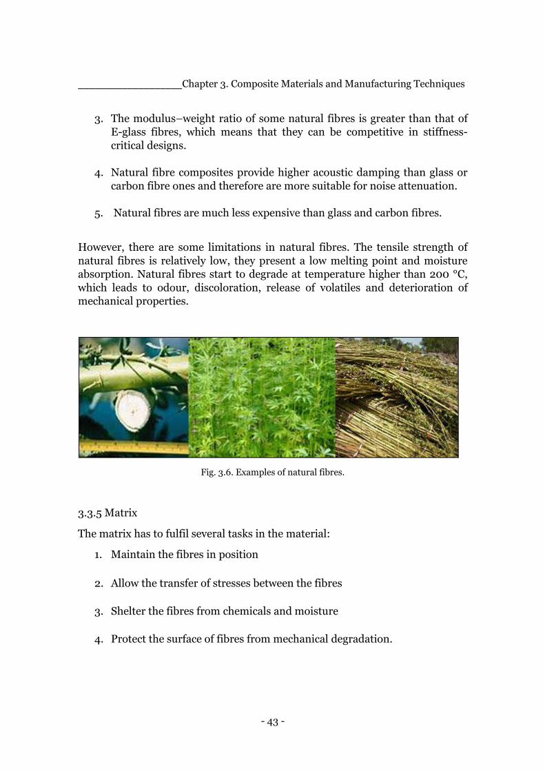
- 43 -
___________________Chapter 3. Composite Materials and Manufacturing Techniques
3. The modulus–weight ratio of some natural fibres is greater than that of
E-glass fibres, which means that they can be competitive in stiffness-
critical designs.
4. Natural fibre composites provide higher acoustic damping than glass or
carbon fibre ones and therefore are more suitable for noise attenuation.
5. Natural fibres are much less expensive than glass and carbon fibres.
However, there are some limitations in natural fibres. The tensile strength of
natural fibres is relatively low, they present a low melting point and moisture
absorption. Natural fibres start to degrade at temperature higher than 200 °C,
which leads to odour, discoloration, release of volatiles and deterioration of
mechanical properties.
Fig. 3.6. Examples of natural fibres.
3.3.5 Matrix
The matrix has to fulfil several tasks in the material:
1. Maintain the fibres in position
2. Allow the transfer of stresses between the fibres
3. Shelter the fibres from chemicals and moisture
4. Protect the surface of fibres from mechanical degradation.
- 44 -
___________________Chapter 3. Composite Materials and Manufacturing Techniques
Even though the matrix does not play a main role in the material’s tensile load
carrying ability, its influence in the compression properties is not to be under
estimated, in fact it provides lateral support against the possibility of fibre
buckling under compressive loading. It is also important for the inter lamina
and in-plane shear properties of the composite material. The interaction
between matrix and fibres is to be envisaged in designing damage tolerant
structures. The processing and defects in the composite material depend
strongly on the processing characteristic of the matrix such for example the
liquid viscosity, the curing temperature and the curing time.
3.3.5.1 Different types of polymeric matrixes
Among the different types of matrix there are the thermoset polymers, mainly
used for long fibre-reinforced composite material thanks to their low viscosity,
thermoplastic polymers, often used with short fibres even if there is an
increasing interest towards them thanks to their recycling possibility. Other
types of matrixes are the metallic and ceramic ones which are mainly used in
high temperature applications. The focus in this paragraph will be directed
towards polymer matrixes and in particular thermoset ones because of the
material chosen for this project work.
The two types of polymeric materials potentially used as matrix, thermoset and
thermoplastic, present a major difference which affects their internal structure
and their behaviour. The polymeric chains of a thermoplastic material are
linked between themselves with weak intermolecular forces, van der Waals and
hydrogen bonds. This allows the chains, once the material is heated, to flow on
each other and acquire a new shape if a pressure is applied on them.
Thermoset’s chains, on the other hand, are chemically linked to each other by
chemical cross-links, forming a rigid, three-dimensional network structure, the
result of this architecture is that thermosets cannot be melt with the supply of
heat.
Two characteristics of polymeric solids can be pointed out, which are not found
in metals under normal conditions, their mechanical properties strongly depend
on temperature and on the loading rate. As far as it concerns the temperature
dependence, near to glass transition temperature the behaviour of the material
changes from hard, sometimes brittle, to soft, highly viscoelastic, that leads to a
reduction of some orders of magnitude of the modulus.
The main concern in the choice of a matrix are its mechanical properties, the
most valued ones are:
- 45 -
___________________Chapter 3. Composite Materials and Manufacturing Techniques
1. The tensile modulus, which affects the compressive strength of the
composite
2. The tensile strength, which governs the intraply cracking in a composite
laminate
3. The fracture toughness, which influences ply delamination and crack
growth.
For polymer matrixes also a good dimensional stability at elevated
temperatures, which means a high glass transition temperature, and resistance
to moisture and solvents, which means that the polymer should dissolve, swell
or other degradation mechanisms when in hot–wet environments, are desirable
qualities. Thermoset polymers, also known as resins, are usually composed of
low molecular weight chains which results in a liquid with low viscosity. This
characteristic is really useful because it favours the wetting of the fibres without
the need of high temperature or high pressure. The wetting of the fibres’ surface
is important for a good interaction between fibres and matrix and hence good
mechanical performances. Resins also exhibit thermal stability and chemical
resistance. Some disadvantages of working with thermoset polymers are:
1. Limited storage life at room temperature
2. Long fabrication time in the mold, due to the curing process
3. Low strain-to-failure which also contributes to their low impact
strengths.
The thermoset polymer chosen for the production on the composite material in
this project is epoxy resin which is a low molecular weight resin containing
epoxide groups, a three member ring of one atom of oxygen and two carbons.
Even though it presents higher costs and longer the curing time compared to
other polymers, it presents some interesting advantages
1. Absence of volatile matters during cure
2. Low shrinkage during cure
3. Excellent resistance to chemicals and solvents
4. Excellent adhesion to a wide variety of fillers, fibres and other
substrates.
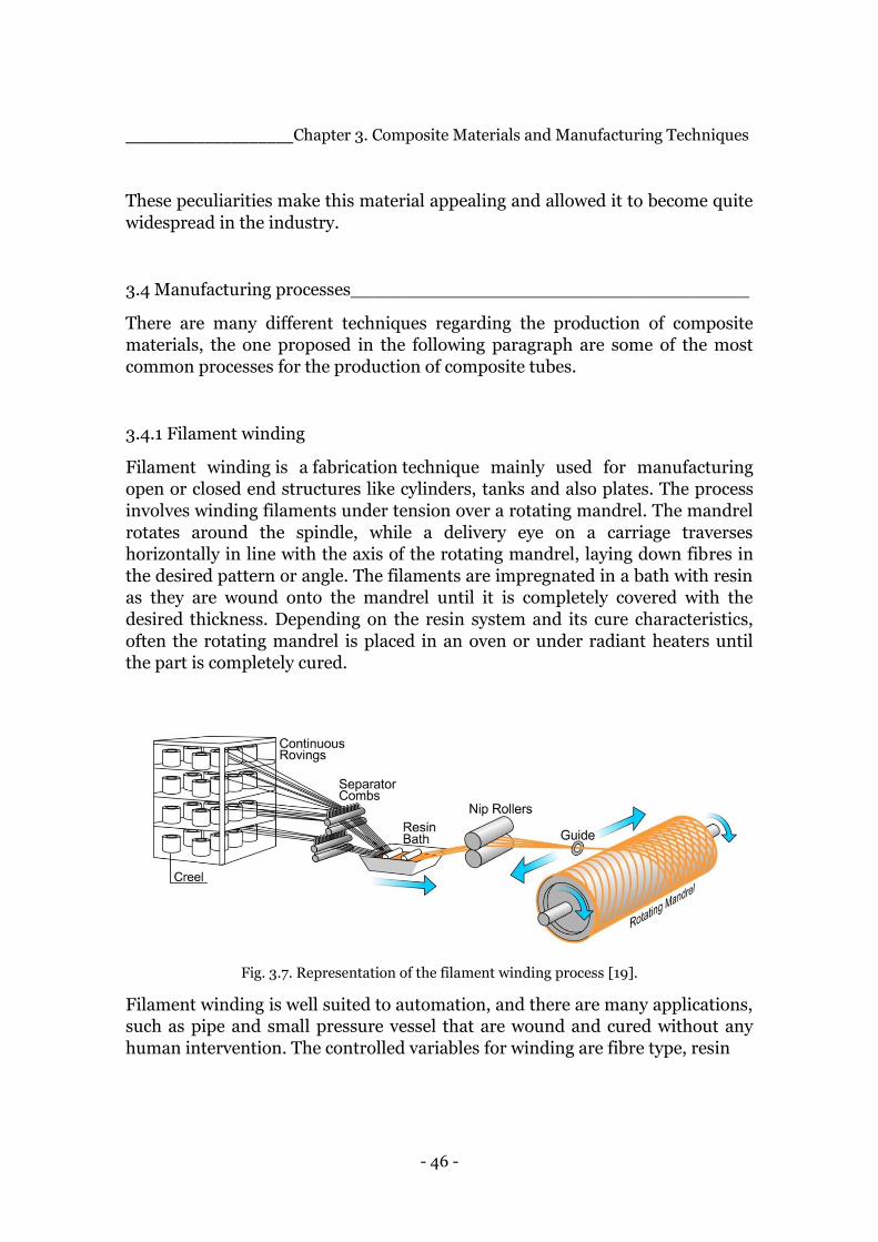
- 46 -
___________________Chapter 3. Composite Materials and Manufacturing Techniques
These peculiarities make this material appealing and allowed it to become quite
widespread in the industry.
3.4 Manufacturing processes___________________________________
There are many different techniques regarding the production of composite
materials, the one proposed in the following paragraph are some of the most
common processes for the production of composite tubes.
3.4.1 Filament winding
Filament winding is a fabrication technique mainly used for manufacturing
open or closed end structures like cylinders, tanks and also plates. The process
involves winding filaments under tension over a rotating mandrel. The mandrel
rotates around the spindle, while a delivery eye on a carriage traverses
horizontally in line with the axis of the rotating mandrel, laying down fibres in
the desired pattern or angle. The filaments are impregnated in a bath with resin
as they are wound onto the mandrel until it is completely covered with the
desired thickness. Depending on the resin system and its cure characteristics,
often the rotating mandrel is placed in an oven or under radiant heaters until
the part is completely cured.
Fig. 3.7. Representation of the filament winding process [19].
Filament winding is well suited to automation, and there are many applications,
such as pipe and small pressure vessel that are wound and cured without any
human intervention. The controlled variables for winding are fibre type, resin

- 47 -
___________________Chapter 3. Composite Materials and Manufacturing Techniques
content, wind angle and thickness of the fibre bundle. The angle at which the
fibre has an effect on the properties of the final product. A high angle "hoop"
will provide circumferential strength, while lower angle patterns, polar or
helical, will provide greater longitudinal tensile strength.
3.4.2 Pultrusion
It was developed in the 50’s by the person considered by many to be “the father of composites,” W. Brandt Goldsworthy. The term pultrusion combines the words, “pull” and “extrusion”. Extrusion is the pushing of material through a shaped die. Pultrusion is a process in which dry, continuous fibers are pulled through a bath of resin and then through a die. The raw resin is almost always a thermosetting resin and is sometimes combined with fillers, catalysts and pigments. The fibre reinforcement becomes fully impregnated with the resin such that all the fibre filaments are thoroughly saturated with the resin mixture. The die serves two purposes, it forces the bundle of wet fibres to conform to the shape you want to create and, since the die is heated, it will cure the resin to set the bundle of fibres into its final shape. After the composite comes out of the die, it is allowed to post-cure while being pulled to the saw where it will be cut to stock lengths. Most often the reinforcement is fiberglass, but it can be carbon, aramid or a mixture.
Fig. 3.8. Representation of the pultrusion process [19].

- 48 -
___________________Chapter 3. Composite Materials and Manufacturing Techniques
A variation is Pull-braiding where, in addition to the continuous fibres being
pulled into the die, a braiding machine will apply a layer of fibres that acts to
improve structural properties in other fibre orientations and adds an
aesthetically pleasing look to the profile. With this technique present a high
stiffness to weight ratio, also known as specific stiffness, that it allows materials
of different mass to be compared quickly in rigidity-sensitive applications where
weight is still a factor. Usually carbon fibres do extremely well in this area, being
about 3 times stiffer than steel and aluminium for a given weight. One of the
advantages of this method is the ability to easily make tubes with specific wall-
thicknesses, the inside diameter of a pultruded tube is determined by a
mandrel, which is easy to exchange for a different sized one, making it easy to
produce tubes with varying wall thickness. Furthermore it’s easy to machine due
to the fact that the products are light structures.
3.4.3 Roll Wrapping
Roll-wrapping involves the applying of resin pre-impregnated composite fibre
cloth around a mandrel. The outer diameter of the mandrel thus determines the
inner diameter of the final tube. The mandrel and cloth are then spiral wrapped
with a consolidation tape under tension to hold the laminate in place during the
curing phase. After curing, the mandrel is extracted to leave the tube ready for
machining or finishing as necessary. Since the matrix and resin are premixed in
a temperature and particle controlled environment, the fibre volume fraction
can be tightly controlled, an important parameter that affects the mechanical
properties of the final product. The ease of adding or subtracting reinforcement
make it possible to create custom end products to fit nearly any composite tube
need.
3.5 Applications___________________________________________
The major structural application areas for fibre-reinforced composite materials
include aircraft and military applications , automotive, sporting goods, marine
and infrastructure. They are also used in electronics, for example for printed
circuit boards, building construction, for example or floor beams, furniture, like
chair springs, power industry, as for Eolic turbines, oil industry, for example in
offshore oil platforms, medical industry, for example for bone plates for fracture
fixation, implants, and prosthetics, and in many other industrial products.
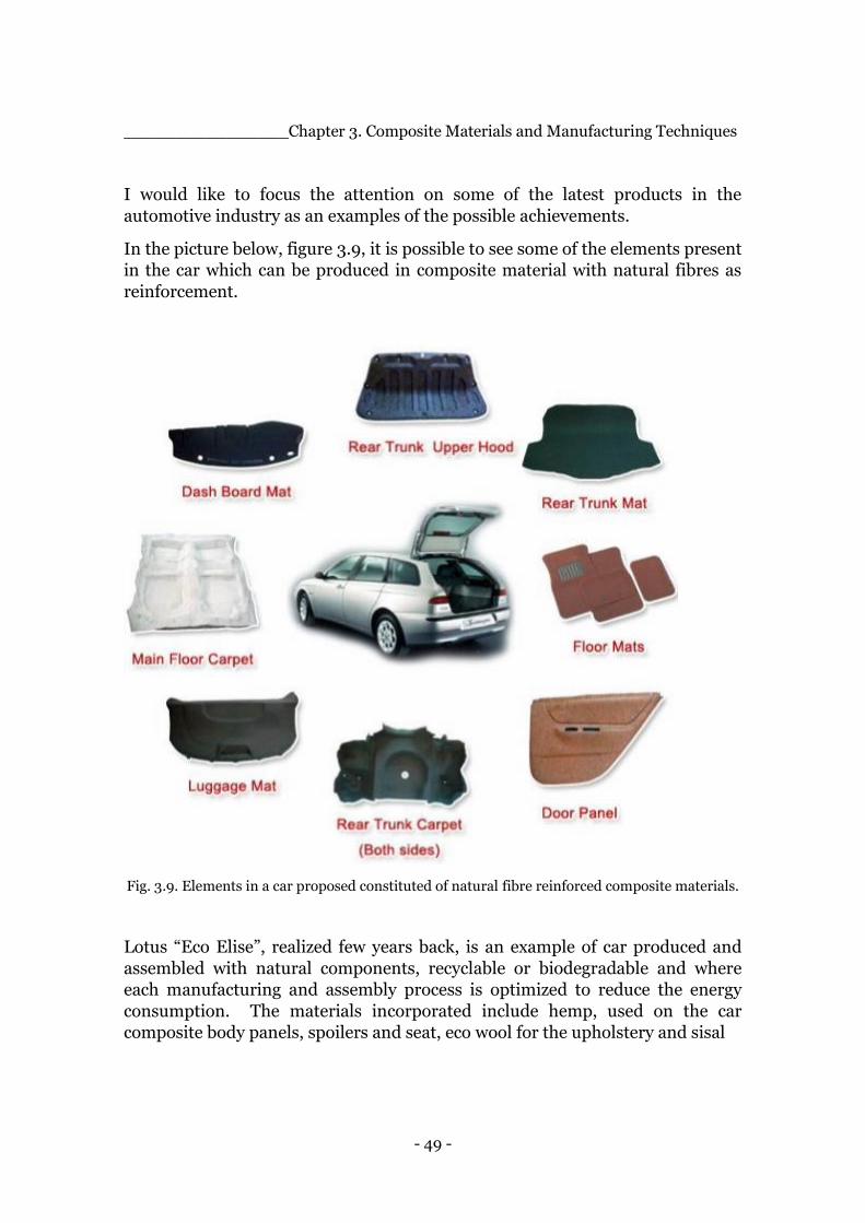
- 49 -
________________Chapter 3. Composite Materials and Manufacturing Techniques
I would like to focus the attention on some of the latest products in the
automotive industry as an examples of the possible achievements.
In the picture below, figure 3.9, it is possible to see some of the elements present
in the car which can be produced in composite material with natural fibres as
reinforcement.
Fig. 3.9. Elements in a car proposed constituted of natural fibre reinforced composite materials.
Lotus “Eco Elise”, realized few years back, is an example of car produced and
assembled with natural components, recyclable or biodegradable and where
each manufacturing and assembly process is optimized to reduce the energy
consumption. The materials incorporated include hemp, used on the car
composite body panels, spoilers and seat, eco wool for the upholstery and sisal
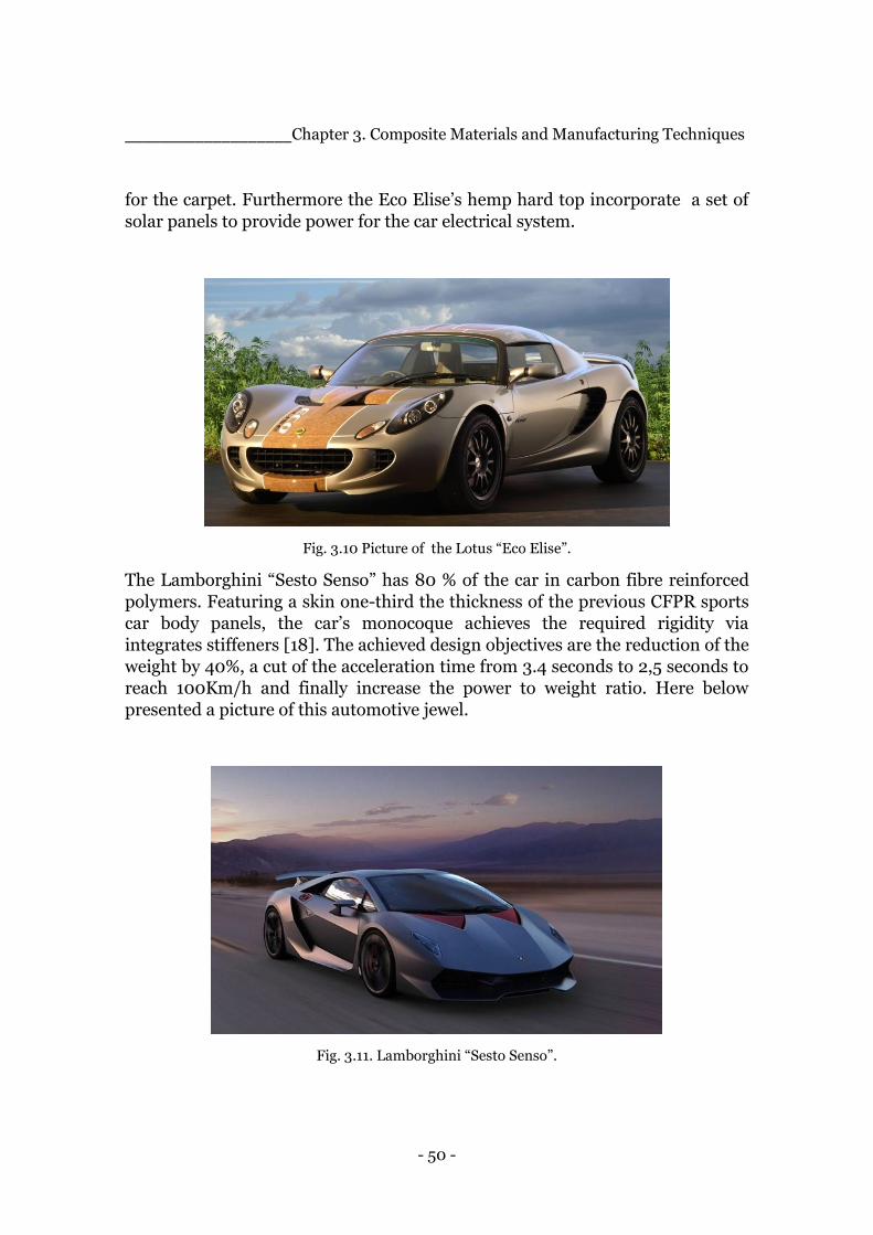
- 50 -
___________________Chapter 3. Composite Materials and Manufacturing Techniques
for the carpet. Furthermore the Eco Elise’s hemp hard top incorporate a set of
solar panels to provide power for the car electrical system.
Fig. 3.10 Picture of the Lotus “Eco Elise”.
The Lamborghini “Sesto Senso” has 80 % of the car in carbon fibre reinforced
polymers. Featuring a skin one-third the thickness of the previous CFPR sports
car body panels, the car’s monocoque achieves the required rigidity via
integrates stiffeners [18]. The achieved design objectives are the reduction of the
weight by 40%, a cut of the acceleration time from 3.4 seconds to 2,5 seconds to
reach 100Km/h and finally increase the power to weight ratio. Here below
presented a picture of this automotive jewel.
Fig. 3.11. Lamborghini “Sesto Senso”.
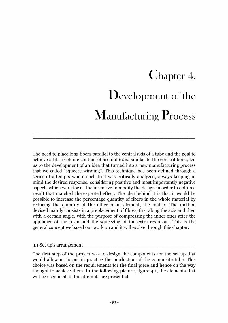
- 51 -
Chapter 4.
Development of the
Manufacturing Process
_______________________________________________________________________
_______________________________________________________________________
The need to place long fibers parallel to the central axis of a tube and the goal to
achieve a fibre volume content of around 60%, similar to the cortical bone, led
us to the development of an idea that turned into a new manufacturing process
that we called “squeeze-winding”. This technique has been defined through a
series of attempts where each trial was critically analyzed, always keeping in
mind the desired response, considering positive and most importantly negative
aspects which were for us the incentive to modify the design in order to obtain a
result that matched the expected effect. The idea behind it is that it would be
possible to increase the percentage quantity of fibers in the whole material by
reducing the quantity of the other main element, the matrix. The method
devised mainly consists in a preplacement of fibres, first along the axis and then
with a certain angle, with the purpose of compressing the inner ones after the
appliance of the resin and the squeezing of the extra resin out. This is the
general concept we based our work on and it will evolve through this chapter.
4.1 Set up’s arrangement_________________________________________________
The first step of the project was to design the components for the set up that
would allow us to put in practice the production of the composite tube. This
choice was based on the requirements for the final piece and hence on the way
thought to achieve them. In the following picture, figure 4.1, the elements that
will be used in all of the attempts are presented.
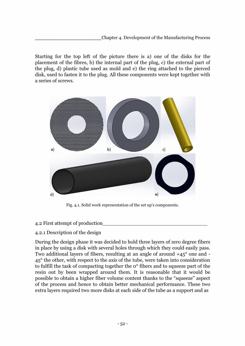
- 52 -
___________________________Chapter 4. Development of the Manufacturing Process
Starting for the top left of the picture there is a) one of the disks for the
placement of the fibres, b) the internal part of the plug, c) the external part of
the plug, d) plastic tube used as mold and e) the ring attached to the pierced
disk, used to fasten it to the plug. All these components were kept together with
a series of screws.
Fig. 4.1. Solid work representation of the set up’s components.
4.2 First attempt of production_________________________________
4.2.1 Description of the design
During the design phase it was decided to hold three layers of zero degree fibers
in place by using a disk with several holes through which they could easily pass.
Two additional layers of fibers, resulting at an angle of around +45° one and -
45° the other, with respect to the axis of the tube, were taken into consideration
to fulfill the task of compacting together the 0° fibers and to squeeze part of the
resin out by been wrapped around them. It is reasonable that it would be
possible to obtain a higher fiber volume content thanks to the “squeeze” aspect
of the process and hence to obtain better mechanical performance. These two
extra layers required two more disks at each side of the tube as a support and as
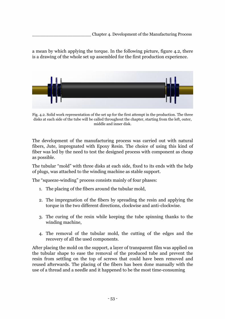
- 53 -
______________________ Chapter 4. Development of the Manufacturing Process
a mean by which applying the torque. In the following picture, figure 4.2, there
is a drawing of the whole set up assembled for the first production experience.
Fig. 4.2. Solid work representation of the set up for the first attempt in the production. The three
disks at each side of the tube will be called throughout the chapter, starting from the left, outer,
middle and inner disk.
The development of the manufacturing process was carried out with natural
fibers, Jute, impregnated with Epoxy Resin. The choice of using this kind of
fiber was led by the need to test the designed process with component as cheap
as possible.
The tubular “mold” with three disks at each side, fixed to its ends with the help
of plugs, was attached to the winding machine as stable support.
The “squeeze-winding” process consists mainly of four phases:
1. The placing of the fibers around the tubular mold,
2. The impregnation of the fibers by spreading the resin and applying the
torque in the two different directions, clockwise and anti-clockwise.
3. The curing of the resin while keeping the tube spinning thanks to the
winding machine,
4. The removal of the tubular mold, the cutting of the edges and the
recovery of all the used components.
After placing the mold on the support, a layer of transparent film was applied on
the tubular shape to ease the removal of the produced tube and prevent the
resin from settling on the top of screws that could have been removed and
reused afterwards. The placing of the fibers has been done manually with the
use of a thread and a needle and it happened to be the most time-consuming
- 54 -
__________________________ Chapter 4. Development of the Manufacturing Process
step of the whole process. The thread was necessary to make a handle able to
pull the fiber on the other side of the disk since the eye of the needle was too big
to fit in the holes of the disk. Three layers of 0° fibers were proposed in this first
trial as a good compromise between a non-too thin thickness of the final tube
and the need to well impregnate all the underlying layers. Other two layers were
placed, fixed at the extremities of the correspondent supporting disks, the ones
that were supposed to be turned after the impregnation . The middle and
external disks were placed directly next to the inner disk, so the extra length of
the fibers, necessary to achieve an angle of 45° starting from 0° during the
appliance of the torque, was let loose on one side, as it is possible to see in figure
4.3.
Fig. 4.3. Photo of the production in progress of the tube before applying the torque at the two
most external disks.
This choice was done in order to prevent the fibers from changing position and
getting entangled with the others. The time necessary for each layer of fibers
was around 5 hours, so a total of about 25 hours was needed for the placing of
the fibers for one tube. Before beginning with the second step, a cover on the
floor and on some components of the winding machine was in order because we
expected some dripping of the resin. The epoxy resin, RIMR135, was mixed with
a slow hardener, RIMH137, that would take eight hours pot life, time enough to
complete the second step. The mass proportion used in the mixture was 100:32

- 55 -
__________________________ Chapter 4. Development of the Manufacturing Process
between the resin and the hardener and the total volume of the mixture
prepared was 2 liters. The spreading of the resin was carried out with the use of
a paint-brush. The resin presented a low viscosity and it was observed a non-
negligible dripping, yet this characteristic favored the impregnation of the
natural fibers, which quickly turned into a darker color. The torque was applied
with the use of clamps, first on one side of the tube and then on the other, for
both the layers with tilted fibers. Due to the manual application of the torque
and the tendency of natural fibers to relax it was not possible to measure the
applied torque intensity but its appliance was carried out, for all the tubes, by
the same person trained in handling manual tools so that a good degree of
repeatability could be expected. Another potential advantage of the appliance of
the torque and the resulting flow of resin towards the outside is that this flow
could carry out bubbles of entrapped air. To better compact all the layers two
metal wires were wrapped around the edges of the tube, that were successively
removed by cutting the edges of the produced tube. Once the resin had been
completely spread on the fibers, peel ply was used to cover them, a thin film that
had the purpose of providing a smooth final surface of the tube and at the same
time allowed the flow of the extra resin through it, see picture 4.4 for a visual
clarification.
Fig. 4.4. Appearance of the semi-result of production after the second step.

- 56 -
__________________________ Chapter 4. Development of the Manufacturing Process
The structure had been kept spinning at low velocity for the whole curing
process, thanks to the winding machine on which it was mounted. Once the
resin was completely cured, after 24 hours, we proceeded in the last step,
removing the produced tube from the mold which we performed thanks to the
use of a press. Once freed, we cut the edges of the composite tube to have a
section perpendicular to the axis.
Fig. 4.5. First tube produced with the ancestor of the ”squeeze winding” process.
4.2.2 Evaluation of aspects to improve
This first attempt presented several issues. The main problem was the fact that
the whole process was conducted manually and the fibers were placed one by
one through the holes of the disks, pulled with the help of a needle and a thread.
This influenced the amount of time necessary to perform the first step, the
precision with which the zero degree angle was obtain and the presence in the
tube of regions more dense than others, this step required an improvement to
reduce time and efforts. During this project we did not switch to an automatized
system, even if from a conceptual point of view wouldn’t be hard to design. The
concern was on proving the effectiveness of the process itself, choosing a
compromise between resources used and time of production.
The appliance of the torque presented also some difficulties, the ring attached to
the disk to fix it on the plug resulted to be slippery and it was also problematic
to reach the ring itself due to the presence of fibers. Furthermore the fibers
placed on the middle and external disk, presented a high friction both with the
fibers beneath, the ones at 0° already impregnated, and with the metal of the
holes within which they were fastened. This lead to a displacement of the fibers
on the tube surface, the need to straighten them up and the result was an
irregular surface, as can be notices in figure 4.5. All of these elements lead to a
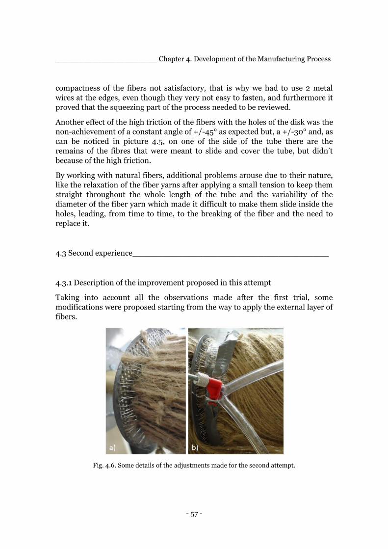
- 57 -
______________________ Chapter 4. Development of the Manufacturing Process
compactness of the fibers not satisfactory, that is why we had to use 2 metal
wires at the edges, even though they very not easy to fasten, and furthermore it
proved that the squeezing part of the process needed to be reviewed.
Another effect of the high friction of the fibers with the holes of the disk was the
non-achievement of a constant angle of +/-45° as expected but, a +/-30° and, as
can be noticed in picture 4.5, on one of the side of the tube there are the
remains of the fibres that were meant to slide and cover the tube, but didn’t
because of the high friction.
By working with natural fibers, additional problems arouse due to their nature,
like the relaxation of the fiber yarns after applying a small tension to keep them
straight throughout the whole length of the tube and the variability of the
diameter of the fiber yarn which made it difficult to make them slide inside the
holes, leading, from time to time, to the breaking of the fiber and the need to
replace it.
4.3 Second experience_______________________________________
4.3.1 Description of the improvement proposed in this attempt
Taking into account all the observations made after the first trial, some
modifications were proposed starting from the way to apply the external layer of
fibers.
Fig. 4.6. Some details of the adjustments made for the second attempt.
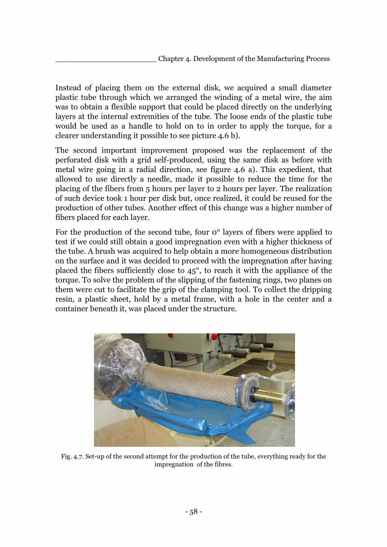
- 58 -
______________________ Chapter 4. Development of the Manufacturing Process
Instead of placing them on the external disk, we acquired a small diameter
plastic tube through which we arranged the winding of a metal wire, the aim
was to obtain a flexible support that could be placed directly on the underlying
layers at the internal extremities of the tube. The loose ends of the plastic tube
would be used as a handle to hold on to in order to apply the torque, for a
clearer understanding it possible to see picture 4.6 b).
The second important improvement proposed was the replacement of the
perforated disk with a grid self-produced, using the same disk as before with
metal wire going in a radial direction, see figure 4.6 a). This expedient, that
allowed to use directly a needle, made it possible to reduce the time for the
placing of the fibers from 5 hours per layer to 2 hours per layer. The realization
of such device took 1 hour per disk but, once realized, it could be reused for the
production of other tubes. Another effect of this change was a higher number of
fibers placed for each layer.
For the production of the second tube, four 0° layers of fibers were applied to
test if we could still obtain a good impregnation even with a higher thickness of
the tube. A brush was acquired to help obtain a more homogeneous distribution
on the surface and it was decided to proceed with the impregnation after having
placed the fibers sufficiently close to 45°, to reach it with the appliance of the
torque. To solve the problem of the slipping of the fastening rings, two planes on
them were cut to facilitate the grip of the clamping tool. To collect the dripping
resin, a plastic sheet, hold by a metal frame, with a hole in the center and a
container beneath it, was placed under the structure.
Fig. 4.7. Set-up of the second attempt for the production of the tube, everything ready for the
impregnation of the fibres.
- 59 -
______________________ Chapter 4. Development of the Manufacturing Process
In this second experience, pigments for the epoxy resin were used in order to
obtain a red colour that could potentially be useful in the image processing
phase. Taking into account all these modifications, the second tube was
produced following the same main steps described in the previous paragraph.
4.3.2 Evaluation of aspects that need improvement
The main problem from this second experience was the way the torque on the
final layer was applied. The set-up with the ringed tube was proven to be not a
good choice for the following reasons:
1. The tubes were not fixed to the extremities so, by turning them, they
tended to move toward the center of the structure and they resulted not
able to keep the fibers in tension, a necessary condition to provide the
desired compaction.
2. A round of tape was applied between the +45 degree fibers and the -45
one in order to avoid a displacement of the underneath fibers but the
movement of the ringed tubes resulted characterized by a high friction.
3. The tubes were too flexible and the attempt to turn them resulted more in
a pulling that made the turning even harder.
4. The handles obtained with the edges of the ringed tubes resulted very
slippery, especially with the gloves wet by the resin.
5. The fibers presented an uneven angle throughout the whole length of the
tube, with a higher angle close to its edges to underline the fact that the
torque’s effect was just at the very edges of the tube instead of being
propagated throughout the whole length.
6. The placing of the fibres on the ringed tubes resulted to be more difficult
than on the disks due to is not fixed nature and also the preparation of
the ringed tubes required a longer time, double than the wrapping of
metal wire around the disks.
7. Instead of the metal wire, in this second experience, zip ties were used to
better hold in position the fibres from the final layer and help to compact
them.
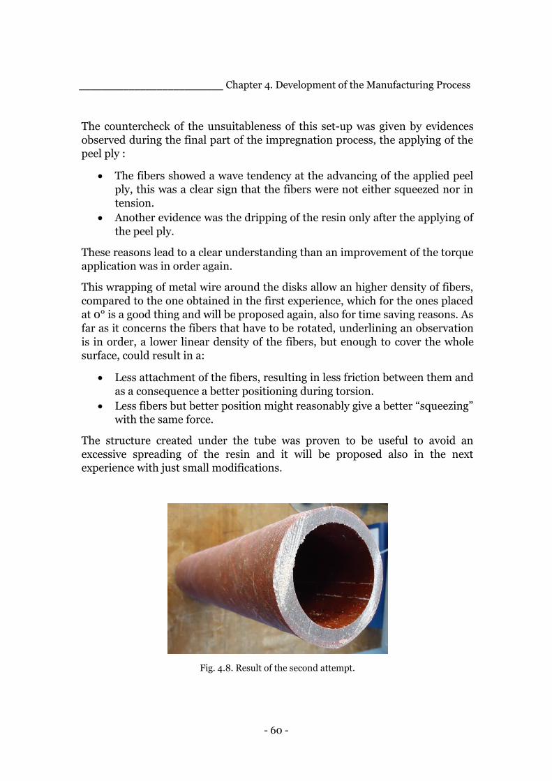
- 60 -
__________________________ Chapter 4. Development of the Manufacturing Process
The countercheck of the unsuitableness of this set-up was given by evidences
observed during the final part of the impregnation process, the applying of the
peel ply :
The fibers showed a wave tendency at the advancing of the applied peel
ply, this was a clear sign that the fibers were not either squeezed nor in
tension.
Another evidence was the dripping of the resin only after the applying of
the peel ply.
These reasons lead to a clear understanding than an improvement of the torque
application was in order again.
This wrapping of metal wire around the disks allow an higher density of fibers,
compared to the one obtained in the first experience, which for the ones placed
at 0° is a good thing and will be proposed again, also for time saving reasons. As
far as it concerns the fibers that have to be rotated, underlining an observation
is in order, a lower linear density of the fibers, but enough to cover the whole
surface, could result in a:
Less attachment of the fibers, resulting in less friction between them and
as a consequence a better positioning during torsion.
Less fibers but better position might reasonably give a better “squeezing”
with the same force.
The structure created under the tube was proven to be useful to avoid an
excessive spreading of the resin and it will be proposed also in the next
experience with just small modifications.
Fig. 4.8. Result of the second attempt.
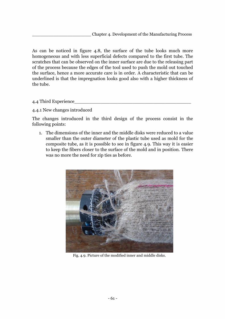
- 61 -
______________________ Chapter 4. Development of the Manufacturing Process
As can be noticed in figure 4.8, the surface of the tube looks much more
homogeneous and with less superficial defects compared to the first tube. The
scratches that can be observed on the inner surface are due to the releasing part
of the process because the edges of the tool used to push the mold out touched
the surface, hence a more accurate care is in order. A characteristic that can be
underlined is that the impregnation looks good also with a higher thickness of
the tube.
4.4 Third Experience________________________________________
4.4.1 New changes introduced
The changes introduced in the third design of the process consist in the
following points:
1. The dimensions of the inner and the middle disks were reduced to a value
smaller than the outer diameter of the plastic tube used as mold for the
composite tube, as it is possible to see in figure 4.9. This way it is easier
to keep the fibers closer to the surface of the mold and in position. There
was no more the need for zip ties as before.
Fig. 4.9. Picture of the modified inner and middle disks.
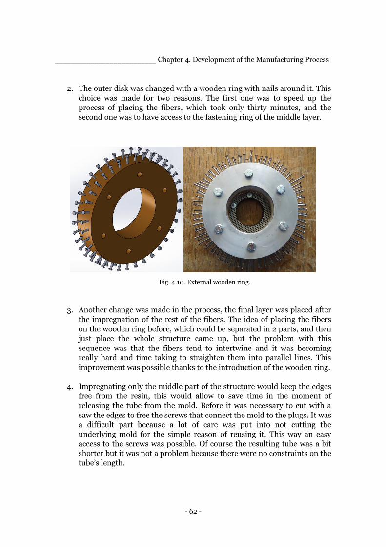
- 62 -
__________________________ Chapter 4. Development of the Manufacturing Process
2. The outer disk was changed with a wooden ring with nails around it. This
choice was made for two reasons. The first one was to speed up the
process of placing the fibers, which took only thirty minutes, and the
second one was to have access to the fastening ring of the middle layer.
Fig. 4.10. External wooden ring.
3. Another change was made in the process, the final layer was placed after
the impregnation of the rest of the fibers. The idea of placing the fibers
on the wooden ring before, which could be separated in 2 parts, and then
just place the whole structure came up, but the problem with this
sequence was that the fibers tend to intertwine and it was becoming
really hard and time taking to straighten them into parallel lines. This
improvement was possible thanks to the introduction of the wooden ring.
4. Impregnating only the middle part of the structure would keep the edges
free from the resin, this would allow to save time in the moment of
releasing the tube from the mold. Before it was necessary to cut with a
saw the edges to free the screws that connect the mold to the plugs. It was
a difficult part because a lot of care was put into not cutting the
underlying mold for the simple reason of reusing it. This way an easy
access to the screws was possible. Of course the resulting tube was a bit
shorter but it was not a problem because there were no constraints on the
tube’s length.
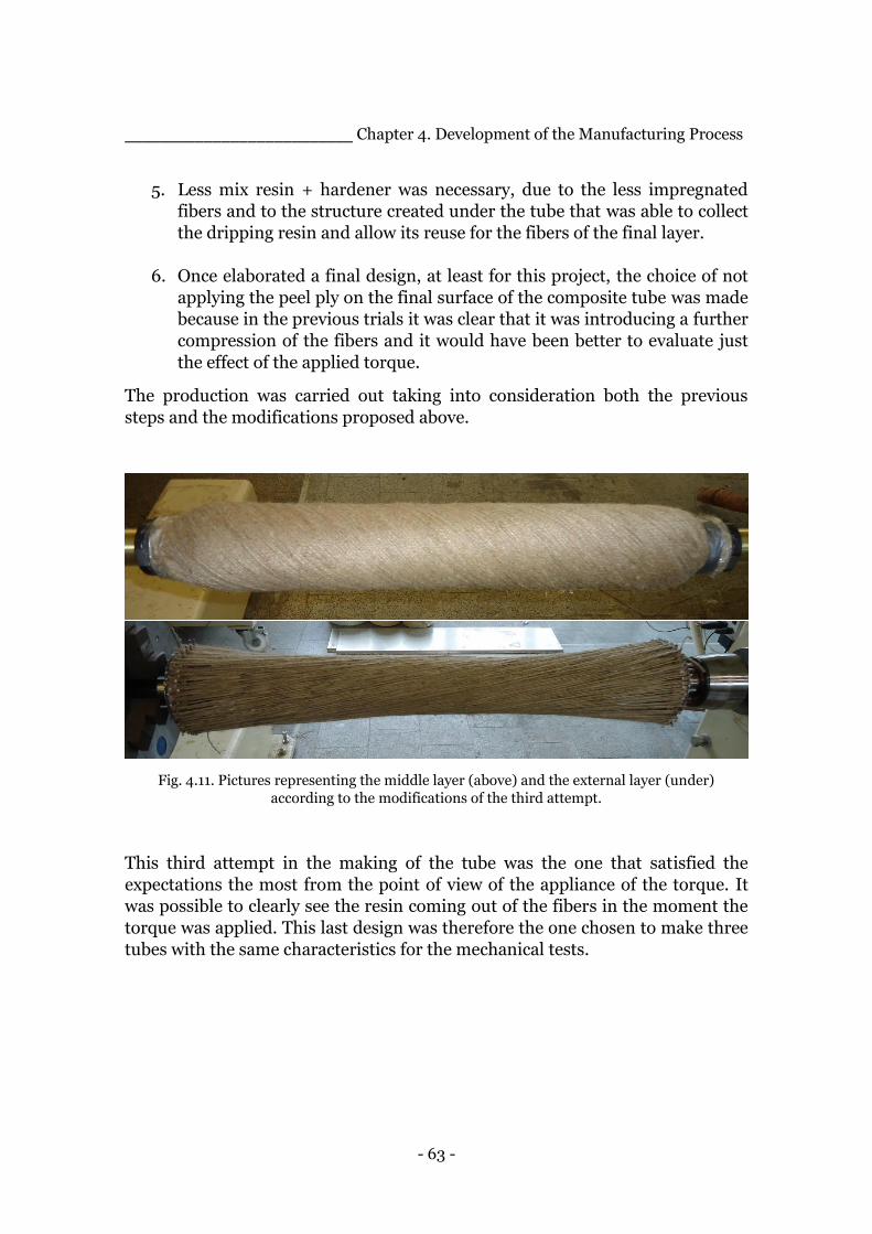
- 63 -
__________________________ Chapter 4. Development of the Manufacturing Process
5. Less mix resin + hardener was necessary, due to the less impregnated
fibers and to the structure created under the tube that was able to collect
the dripping resin and allow its reuse for the fibers of the final layer.
6. Once elaborated a final design, at least for this project, the choice of not
applying the peel ply on the final surface of the composite tube was made
because in the previous trials it was clear that it was introducing a further
compression of the fibers and it would have been better to evaluate just
the effect of the applied torque.
The production was carried out taking into consideration both the previous
steps and the modifications proposed above.
Fig. 4.11. Pictures representing the middle layer (above) and the external layer (under)
according to the modifications of the third attempt.
This third attempt in the making of the tube was the one that satisfied the
expectations the most from the point of view of the appliance of the torque. It
was possible to clearly see the resin coming out of the fibers in the moment the
torque was applied. This last design was therefore the one chosen to make three
tubes with the same characteristics for the mechanical tests.

- 64 -
__________________________ Chapter 4. Development of the Manufacturing Process
4.4.2 Final considerations of the third experience
Even though the design was quite satisfying, there are still some problems that
need to be solved or at least are worth taking into consideration:
1. Due to their nature, natural fibers tend to stick together, this peculiarity
makes it hard and time taking to place them correctly especially for the
ones in the 45 degree layers. Some time was spent brushing them and
there was still a portion of them, even if small, that was not perfectly in
line with the others.
2. Due to the friction between the layer on the move and the one
underlying, it was possible to observe that the angle at which the fibers
were placed was not constant throughout the longitudinal axis of the
tube.
3. The fibers were not completely fixed at the edges but they are held in
position by making them pass through a metal ring, this means that they
can actually slide a bit and this happens specially while brushing them.
The result was that, since some fibers were longer than others, the
“squeezing” was given only by the shorter ones. It is reasonable to
suppose that if able to fix them at a certain length, in a way that would
not take too much time, the effect of compacting of the fibers would be
greater.
4. Another problem that is constant in working with natural fibers is the
fact that they tend to relax, with carbon or glass fibers we would be able
to apply a greater value of force and possibly we could maximize the
squeezing effect. These two reasons lead to the consideration that natural
fibers may not be the most appropriate for this technique, at least in the
way that has been designed. Glass and carbon fibers may be better suited
for this technique.
5. The choice of not using the peel ply affects the final surface and it’s
possible to observe a wavy final surface with fibers that are impregnated
but not completely surrounded by the resin. With this surface it’s more
difficult to evaluate an outer diameter of the composite tube, useful for
further calculation, in particular the one about the fiber volume content.

- 65 -
__________________________ Chapter 4. Development of the Manufacturing Process
The choice of keeping the impregnated fibers spinning for the whole curing time
was proposed again both for the second and the third experience.
Three tubes with this setting and procedure were produced, see picture 4.12,
with the aim of evaluating the repeatability of the process along with the
characteristics from a mechanical and fibre volume content point of view.
The presence in the laboratory of the winding machine allowed the possibility to
compare the results of the three tubes, obtained with the squeeze-winding
technique, with the ones obtained from tubes manufactured with the filament
winding technique, one of the most used in the industry and described in the
previous chapter. In the following chapter, the results of the mechanical test
from both types of tubes will be presented.
Fig. 4.12 Picture representing the three tubes made with the final manufacturing process
developed called “squeeze-winding”.

- 66 -
Chapter 5.
Characterization of the
Squeeze-Winding Process ______________________________________________________________________________________________________________________________________________
The production technique developed and described in the previous chapter,
called Squeeze-winding, is in need of a characterization in terms of the
reproducibility and in terms of the actual performances that the products
display. For this purpose three tubes were produced trying to maintain the same
settings and characteristics in order to evaluate the above-mentioned aspects of
the technique. It is important to underline that the whole process was carried
out manually, both in terms of the placing of the fibres and the appliance of the
resin and the final torque. This aspect of the production inevitably introduces a
higher degree of variability compared to an automatized process. In order to
evaluate the effectiveness of the process developed from a performance point of
view, samples of the as-produced tubes will be compared in compression with
the ones obtained from a tube produced with the well-developed filament
winding technique. The production of the filament wound tube was possible
thanks to the presence and availability of the winding machine in the laboratory
where this experimental activity was carried out, the Institute of Polymer
Material and Plastics Engineering of Clausthal Technical University, sited in the
Harz region in Lower-Saxony, Germany. Another aspect that has been analysed
and described in this chapter is the fibre volume content obtainable with the
new process and it will be compared to the one obtained from the filament
winding technique. Such value is an important parameter that needs to be taken
into consideration to partially account for the mechanical performances of the
produced structure.
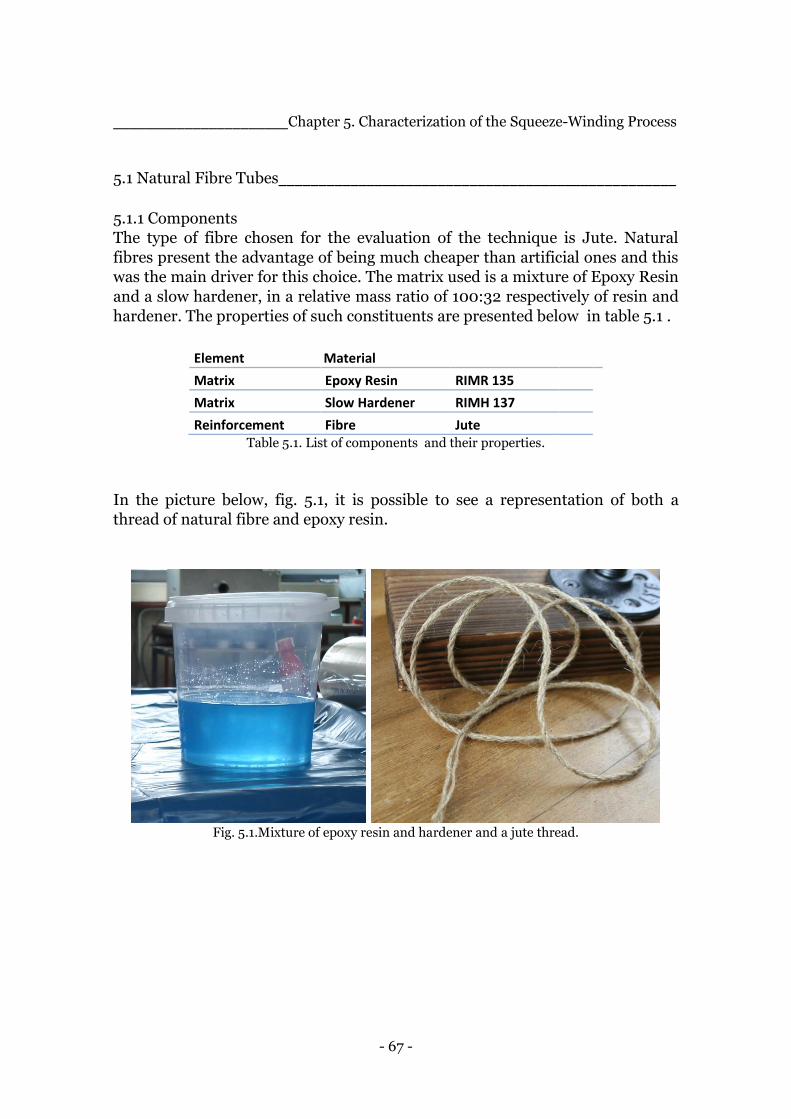
- 67 -
______________________Chapter 5. Characterization of the Squeeze-Winding Process
5.1 Natural Fibre Tubes__________________________________________________
5.1.1 Components
The type of fibre chosen for the evaluation of the technique is Jute. Natural
fibres present the advantage of being much cheaper than artificial ones and this
was the main driver for this choice. The matrix used is a mixture of Epoxy Resin
and a slow hardener, in a relative mass ratio of 100:32 respectively of resin and
hardener. The properties of such constituents are presented below in table 5.1 .
Element Material
Matrix Epoxy Resin RIMR 135
Matrix Slow Hardener RIMH 137
Reinforcement Fibre Jute Table 5.1. List of components and their properties.
In the picture below, fig. 5.1, it is possible to see a representation of both a
thread of natural fibre and epoxy resin.
Fig. 5.1.Mixture of epoxy resin and hardener and a jute thread.

- 68 -
______________________Chapter 5. Characterization of the Squeeze-Winding Process
5.1.2 Production times
The time necessary for the production of each tube was calculated considering
all the steps that characterize the process, which briefly are the placing of the
fibre, the appliance of the uncured matrix and the successive torque, the curing
of the mixture and the demoulding of the produced tube. In table 5.2, it is
possible to see the time associated to each step that characterizes the squeeze
winding technique. It is meaningful to underline that the times presented are
the final ones, longer times were necessary before the optimization of the
process, occurred through the attempts described in the previous chapter. It is
worth mentioning that the winding machine allows the user to choose and set
the desired speed with which it performs the programmed steps, yet some
restrictions presented during its use. Such constrains were due to the need of
keeping the fibres in tension, especially for ones in the two external layers
placed at +/- 45°, they had the important task of compacting the underlying
fibres. The non-negligible tension of the fibres and a lively speed of the guide of
the machine led, for time to time, to the breaking of the fibre itself, the need to
stop the process and replace the thread in order to continue with the
production. However the time required for the production of the desired tube
with the filament winding technique resulted around 3 hours, less compared to
the other process, plus of course the curing and the demoulding time.
Process & Time required to perform it
Phase 1 Placing of the fibres 6 [h]
Phase 2 Impregnation and appliance of the torque 2 [h]
Phase 3 Curing process 24 [h]
Phase 4 Demoulding 1 [h]
Table 5.2. Times associated to the different production phases.
5.1.3 Visual description of the produced tubes
It might be useful to recall that the internal arrangement of the fibres chosen for
the production of the three tubes, with the aim of evaluating the production
process, presents three layers of fibres at 0°, with respect to the axis of the tube,
starting from the inner part of the composite tube and 2 external layers placed
at +/- 45° also with respect its axis. All of the final tubes present a rough
external surface due to the choice of not using the peel ply, a texture generally
used to obtain a smooth final surface.

- 69 -
______________________Chapter 5. Characterization of the Squeeze-Winding Process
The internal surface of the tube presents some tiny bubbles remained entrapped
of few millimetres of diameter. By observing the section of the tube it is possible
to appreciate the impregnation of the natural fibres, even though a more precise
evaluation will be done thanks to the observation of some samples with the optic
microscope.
5.2 Production of the comparative natural fibre tube___________________
The tube, produced with filament winding and used as a comparison for the
characterization of the developed technique, was obtained after a series of three
attempts. In order to start with the production, it is necessary to program the
machine by providing details on the desired product, like the number and order
of layers, the angle of each layer, the thickness of the fibres, the desired length of
the tube and the diameter of the mold. Such informations will allow the
program to calculate the movements of the machine along the different axis.
5.2.1 Brief description of the attempts
The first try was characterized by the challenge to place the fibres of the first
three layers at 0°, like for the tubes previously produced with the new process,
this is usually not done with the filament winding technique. The placing of the
fibres occurred almost with the desired angle, yet some other problems emerged
that led to the understanding that an increase in the angle of the fibre was in
order.
Fig. 5.2. Result of the first attempt in making a 0° fibres tube with filament winding technique.
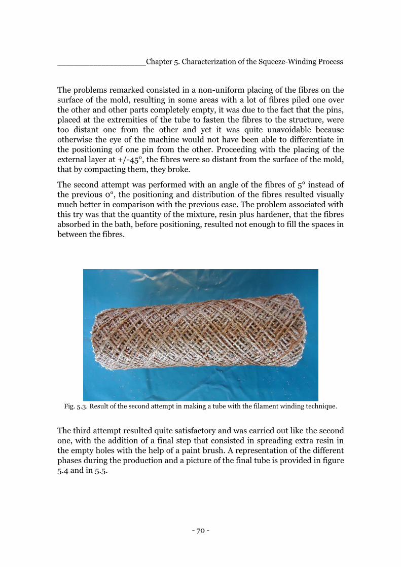
- 70 -
______________________Chapter 5. Characterization of the Squeeze-Winding Process
The problems remarked consisted in a non-uniform placing of the fibres on the
surface of the mold, resulting in some areas with a lot of fibres piled one over
the other and other parts completely empty, it was due to the fact that the pins,
placed at the extremities of the tube to fasten the fibres to the structure, were
too distant one from the other and yet it was quite unavoidable because
otherwise the eye of the machine would not have been able to differentiate in
the positioning of one pin from the other. Proceeding with the placing of the
external layer at +/-45°, the fibres were so distant from the surface of the mold,
that by compacting them, they broke.
The second attempt was performed with an angle of the fibres of 5° instead of
the previous 0°, the positioning and distribution of the fibres resulted visually
much better in comparison with the previous case. The problem associated with
this try was that the quantity of the mixture, resin plus hardener, that the fibres
absorbed in the bath, before positioning, resulted not enough to fill the spaces in
between the fibres.
Fig. 5.3. Result of the second attempt in making a tube with the filament winding technique.
The third attempt resulted quite satisfactory and was carried out like the second
one, with the addition of a final step that consisted in spreading extra resin in
the empty holes with the help of a paint brush. A representation of the different
phases during the production and a picture of the final tube is provided in figure
5.4 and in 5.5.

- 71 -
______________________Chapter 5. Characterization of the Squeeze-Winding Process
Fig. 5.4. Representation of the different stages of the placing of the fibres in the filament
winding technique.
Fig. 5.5. Result of the third attempt in making a tube with the filament winding process.
- 72 -
______________________Chapter 5. Characterization of the Squeeze-Winding Process
5.2.2 Considerations
For all these attempts, the curing process of the resin, necessary to give rigidity
to the matrix, was carried out at normal pressure and ambient temperature.
Another aspect that it is worth mentioning is that the winding machine used is
about 30 years old and it is reasonable to believe that newer winding machines
would present a better positioning system and therefore better final products.
Due to the availability of the machine, this is an aspect that cannot be changed
and so it will not be considered further.
5.3 Mechanical characterization_________________________________
Considering the initial requirements for a tube that could serve as a component
for a bigger structure and that, as a loading condition, it would be subjected
mainly to compression, it was decided to test the tubes just in compression
where it would have been possible to appreciate the effect of the presence of 0°
fibres. The two accessible machines for the compression tests, available in the
laboratory of the Polymer Department of the Technical University of Clausthal
and in the Mechanical Department of Politecnico, had a maximum load of
100kN and 250kN, respectively. To evaluate the load necessary to lead to the
breaking of the tube , an attempt of a compression test was first made with one
of the tubes produced during the development of the process with the machine
from the Polymer Department of TU Clausthal. The maximum load was not
enough even to obtain a significant strain in the tube. This led to the belief that
also a 250 kN load would not have been able to break the tube. A testing of
samples obtained from the tube itself was in order.
5.3.1 Preparation of the samples and settings
After a search for the right compression test standards, the lack of standards
that would refer specifically to samples obtained from tubes and hence samples
with a curved shaped surface, lead to the decision of not following exactly a
specific standard. However the standard ISO 604, Plastics – Determination of
compressive properties, was taken into consideration to maintain at least the
same proportions between the upper and lower bases and the height of the
samples as presented in such standard for parallelepiped specimens. A total
number of 20 specimens, for each tube, were cut with the help of a band saw,
the average dimensions were 15 mm of height and an average angle opening of
18°.
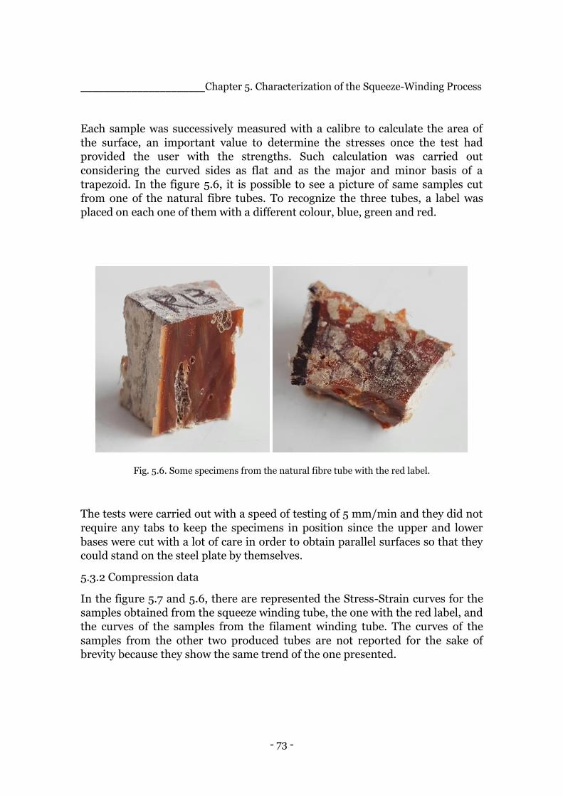
- 73 -
______________________Chapter 5. Characterization of the Squeeze-Winding Process
Each sample was successively measured with a calibre to calculate the area of
the surface, an important value to determine the stresses once the test had
provided the user with the strengths. Such calculation was carried out
considering the curved sides as flat and as the major and minor basis of a
trapezoid. In the figure 5.6, it is possible to see a picture of same samples cut
from one of the natural fibre tubes. To recognize the three tubes, a label was
placed on each one of them with a different colour, blue, green and red.
Fig. 5.6. Some specimens from the natural fibre tube with the red label.
The tests were carried out with a speed of testing of 5 mm/min and they did not
require any tabs to keep the specimens in position since the upper and lower
bases were cut with a lot of care in order to obtain parallel surfaces so that they
could stand on the steel plate by themselves.
5.3.2 Compression data
In the figure 5.7 and 5.6, there are represented the Stress-Strain curves for the
samples obtained from the squeeze winding tube, the one with the red label, and
the curves of the samples from the filament winding tube. The curves of the
samples from the other two produced tubes are not reported for the sake of
brevity because they show the same trend of the one presented.
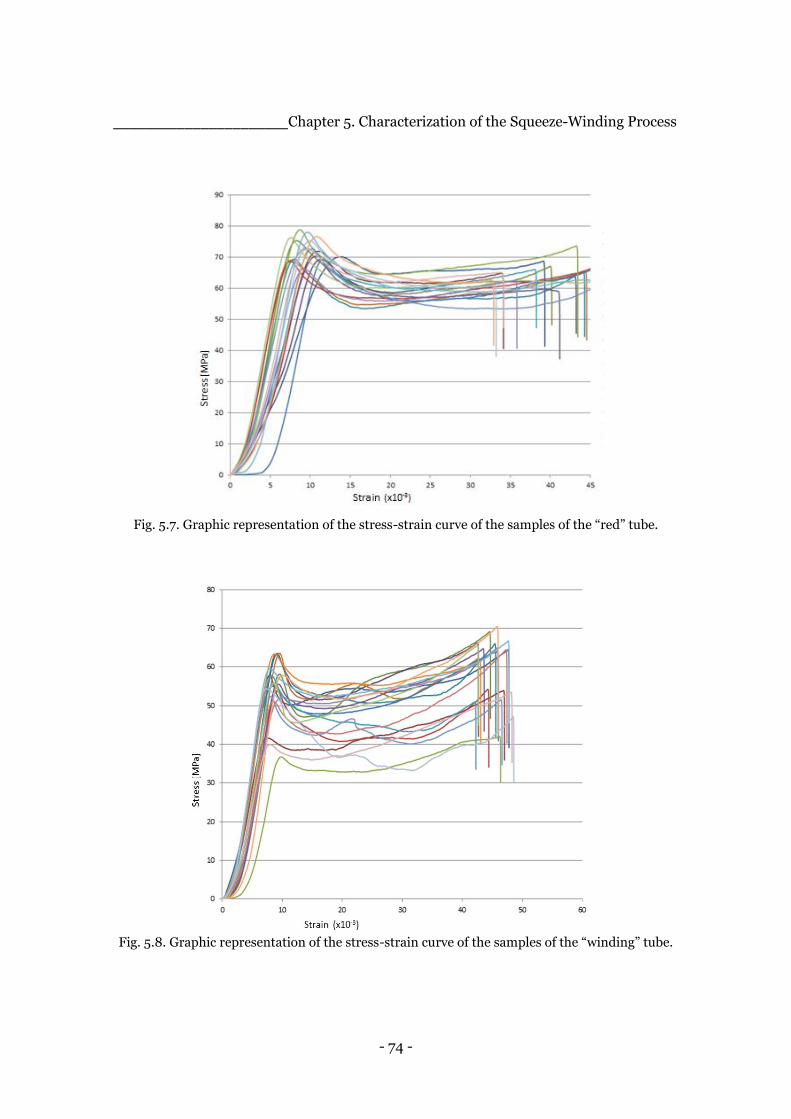
- 74 -
______________________Chapter 5. Characterization of the Squeeze-Winding Process
Fig. 5.7. Graphic representation of the stress-strain curve of the samples of the “red” tube.
Fig. 5.8. Graphic representation of the stress-strain curve of the samples of the “winding” tube.
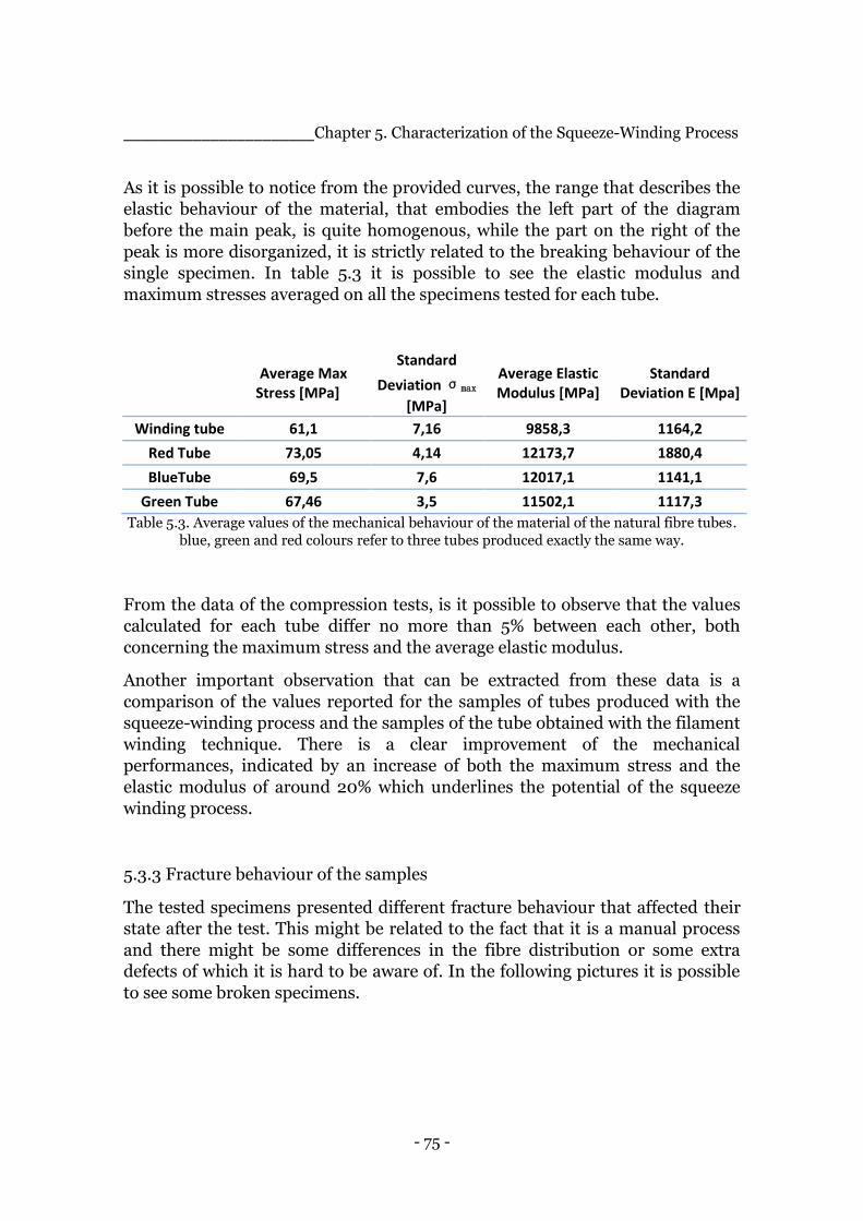
- 75 -
______________________Chapter 5. Characterization of the Squeeze-Winding Process
As it is possible to notice from the provided curves, the range that describes the
elastic behaviour of the material, that embodies the left part of the diagram
before the main peak, is quite homogenous, while the part on the right of the
peak is more disorganized, it is strictly related to the breaking behaviour of the
single specimen. In table 5.3 it is possible to see the elastic modulus and
maximum stresses averaged on all the specimens tested for each tube.
Average Max Stress [MPa]
Standard
Deviation σmax
[MPa]
Average Elastic Modulus [MPa]
Standard Deviation E [Mpa]
Winding tube 61,1 7,16 9858,3 1164,2
Red Tube 73,05 4,14 12173,7 1880,4
BlueTube 69,5 7,6 12017,1 1141,1
Green Tube 67,46 3,5 11502,1 1117,3
Table 5.3. Average values of the mechanical behaviour of the material of the natural fibre tubes.
blue, green and red colours refer to three tubes produced exactly the same way.
From the data of the compression tests, is it possible to observe that the values
calculated for each tube differ no more than 5% between each other, both
concerning the maximum stress and the average elastic modulus.
Another important observation that can be extracted from these data is a
comparison of the values reported for the samples of tubes produced with the
squeeze-winding process and the samples of the tube obtained with the filament
winding technique. There is a clear improvement of the mechanical
performances, indicated by an increase of both the maximum stress and the
elastic modulus of around 20% which underlines the potential of the squeeze
winding process.
5.3.3 Fracture behaviour of the samples
The tested specimens presented different fracture behaviour that affected their
state after the test. This might be related to the fact that it is a manual process
and there might be some differences in the fibre distribution or some extra
defects of which it is hard to be aware of. In the following pictures it is possible
to see some broken specimens.
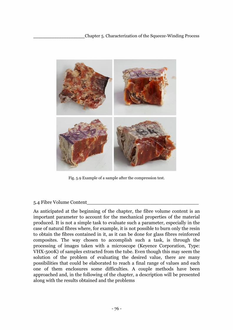
- 76 -
______________________Chapter 5. Characterization of the Squeeze-Winding Process
Fig. 5.9 Example of a sample after the compression test.
5.4 Fibre Volume Content_____________________________________
As anticipated at the beginning of the chapter, the fibre volume content is an
important parameter to account for the mechanical properties of the material
produced. It is not a simple task to evaluate such a parameter, especially in the
case of natural fibres where, for example, it is not possible to burn only the resin
to obtain the fibres contained in it, as it can be done for glass fibres reinforced
composites. The way chosen to accomplish such a task, is through the
processing of images taken with a microscope (Keyence Corporation, Type:
VHX-500K) of samples extracted from the tube. Even though this may seem the
solution of the problem of evaluating the desired value, there are many
possibilities that could be elaborated to reach a final range of values and each
one of them enclosures some difficulties. A couple methods have been
approached and, in the following of the chapter, a description will be presented
along with the results obtained and the problems
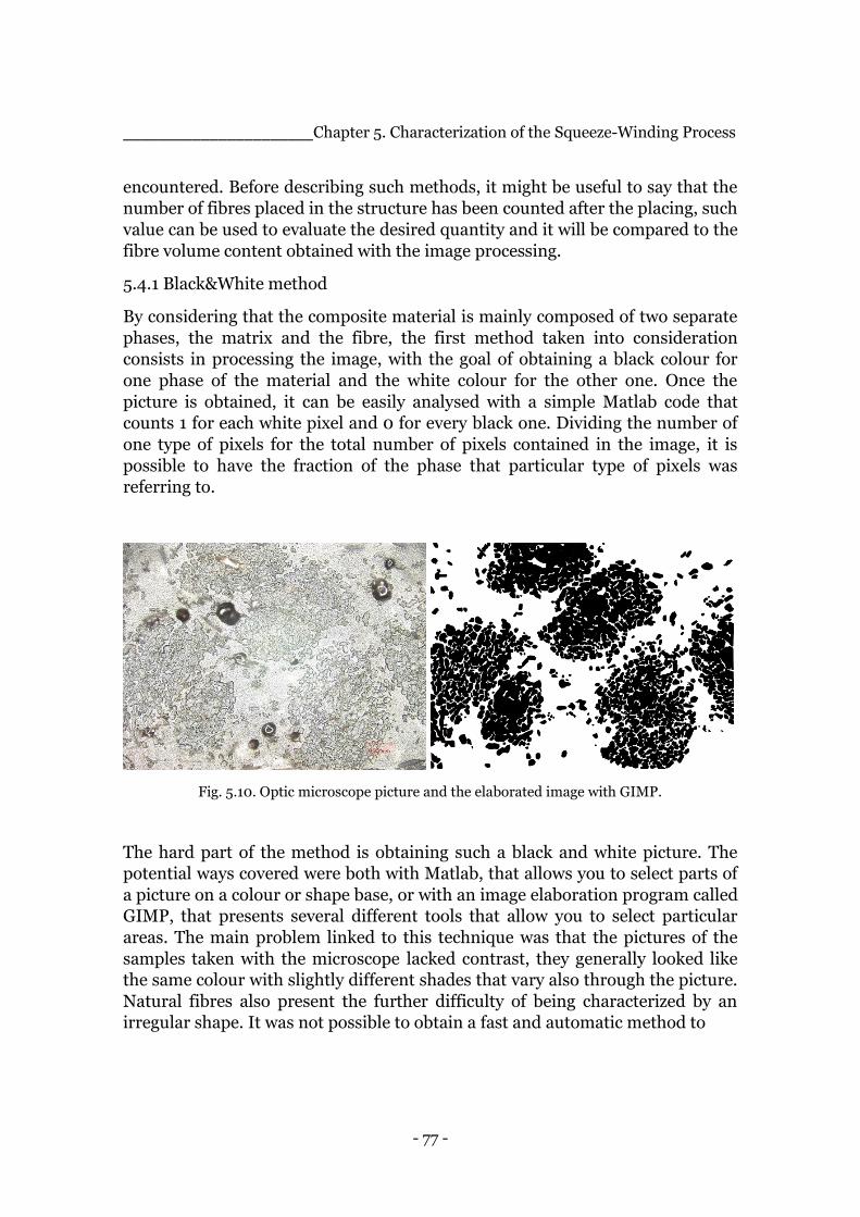
- 77 -
______________________Chapter 5. Characterization of the Squeeze-Winding Process
encountered. Before describing such methods, it might be useful to say that the
number of fibres placed in the structure has been counted after the placing, such
value can be used to evaluate the desired quantity and it will be compared to the
fibre volume content obtained with the image processing.
5.4.1 Black&White method
By considering that the composite material is mainly composed of two separate
phases, the matrix and the fibre, the first method taken into consideration
consists in processing the image, with the goal of obtaining a black colour for
one phase of the material and the white colour for the other one. Once the
picture is obtained, it can be easily analysed with a simple Matlab code that
counts 1 for each white pixel and 0 for every black one. Dividing the number of
one type of pixels for the total number of pixels contained in the image, it is
possible to have the fraction of the phase that particular type of pixels was
referring to.
Fig. 5.10. Optic microscope picture and the elaborated image with GIMP.
The hard part of the method is obtaining such a black and white picture. The
potential ways covered were both with Matlab, that allows you to select parts of
a picture on a colour or shape base, or with an image elaboration program called
GIMP, that presents several different tools that allow you to select particular
areas. The main problem linked to this technique was that the pictures of the
samples taken with the microscope lacked contrast, they generally looked like
the same colour with slightly different shades that vary also through the picture.
Natural fibres also present the further difficulty of being characterized by an
irregular shape. It was not possible to obtain a fast and automatic method to
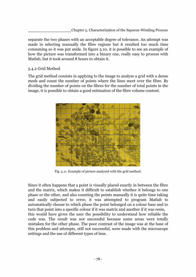
- 78 -
______________________Chapter 5. Characterization of the Squeeze-Winding Process
separate the two phases with an acceptable degree of tolerance. An attempt was
made in selecting manually the fibre regions but it resulted too much time
consuming so it was put aside. In figure 5.10, it is possible to see an example of
how the picture was transformed into a binary one, really easy to process with
Matlab, but it took around 8 hours to obtain it.
5.4.2 Grid Method
The grid method consists in applying to the image to analyse a grid with a dense
mesh and count the number of points where the lines meet over the fibre. By
dividing the number of points on the fibres for the number of total points in the
image, it is possible to obtain a good estimation of the fibre volume content.
Fig. 5.11. Example of picture analysed with the grid method.
Since it often happens that a point is visually placed exactly in between the fibre
and the matrix, which makes it difficult to establish whether it belongs to one
phase or the other, and also counting the points manually it is quite time taking
and easily subjected to error, it was attempted to program Matlab to
automatically choose to which phase the point belonged on a colour base and to
turn that point into a specific colour if it was matrix and another if it was resin,
this would have given the user the possibility to understand how reliable the
code was. The result was not successful because some areas were totally
mistaken for the other phase. The poor contrast of the image was at the base of
this problem and attempts, still not successful, were made with the microscope
settings and the use of different types of lens.
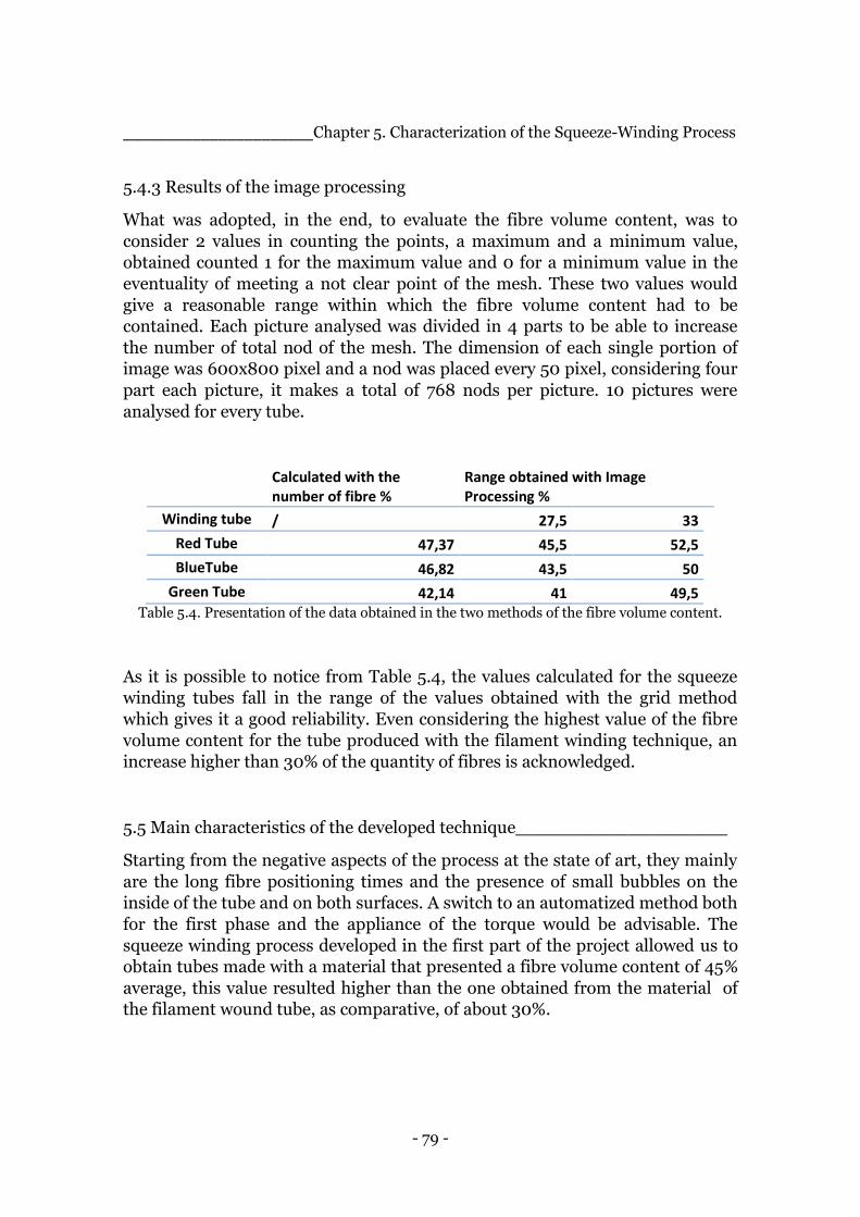
- 79 -
______________________Chapter 5. Characterization of the Squeeze-Winding Process
5.4.3 Results of the image processing
What was adopted, in the end, to evaluate the fibre volume content, was to
consider 2 values in counting the points, a maximum and a minimum value,
obtained counted 1 for the maximum value and 0 for a minimum value in the
eventuality of meeting a not clear point of the mesh. These two values would
give a reasonable range within which the fibre volume content had to be
contained. Each picture analysed was divided in 4 parts to be able to increase
the number of total nod of the mesh. The dimension of each single portion of
image was 600x800 pixel and a nod was placed every 50 pixel, considering four
part each picture, it makes a total of 768 nods per picture. 10 pictures were
analysed for every tube.
Calculated with the number of fibre %
Range obtained with Image Processing %
Winding tube / 27,5 33
Red Tube 47,37 45,5 52,5 BlueTube 46,82 43,5 50
Green Tube 42,14 41 49,5 Table 5.4. Presentation of the data obtained in the two methods of the fibre volume content.
As it is possible to notice from Table 5.4, the values calculated for the squeeze
winding tubes fall in the range of the values obtained with the grid method
which gives it a good reliability. Even considering the highest value of the fibre
volume content for the tube produced with the filament winding technique, an
increase higher than 30% of the quantity of fibres is acknowledged.
5.5 Main characteristics of the developed technique___________________
Starting from the negative aspects of the process at the state of art, they mainly
are the long fibre positioning times and the presence of small bubbles on the
inside of the tube and on both surfaces. A switch to an automatized method both
for the first phase and the appliance of the torque would be advisable. The
squeeze winding process developed in the first part of the project allowed us to
obtain tubes made with a material that presented a fibre volume content of 45%
average, this value resulted higher than the one obtained from the material of
the filament wound tube, as comparative, of about 30%.

- 80 -
______________________Chapter 5. Characterization of the Squeeze-Winding Process
The mechanical properties of both the materials were tested in compression and
an increase both of the load at breaking and of the elastic modulus was
registered, of respectively 15% and 20%. Such improvements of the mechanical
properties can be explained both because of the fibre volume content and the
presence of 0° fibre that this technique allows. Another aspect that is worth
mentioning is that the impregnation of the fibres is quite good and can be
observed in the pictures obtained with the optic microscope, and example is
given in figure 5.12, along with the presence of some bubbles. A good
reproducibility of the process was observed which allowed to obtain values of
the mechanical properties and of the fibre volume content within a close range.
A final aspect to underline is that the desired value of fibre volume content was
around 60%, a possible reason why it was not possible to obtain it, it is link to
the nature of natural fibres that tend to relax and elongate when put under
tension. It is reasonable to think that artificial fibres would be better suited for
the task.
Fig. 5.12. Optic microscope picture of a natural fibre sample.
- 81 -
Chapter 6.
Design and Production of
the Bioinspired Composite Tube _______________________________________________________________________
_______________________________________________________________________
The previous part of this thesis’ work concerned with the developing of a
manufacturing technique that would be suitable to obtain a tubular composite
with a good level of fibre volume content and fibres placed longitudinally to the
axis of the tube. The Squeeze-Winding process has been successively put to the
test with a different type of fibres and a specific internal design. It is important
to underline that the research activity, carried out during these eight months in
the Institute of Polymer Materials and Plastic Engineering of Clausthal, takes its
roots from previous works characterized by the attempt to reproduce some of
the toughening mechanisms of cortical bone. In order to do that, they focused
on the production of laminates with an arrangement of fibres aimed at
recreating the osteonic structure of bone, described in the Chapter 2, at a bigger
scale due to technology limitations. This project takes the concepts understood
from the process of optimization of the design of the internal structure and
reapplies them to the production, with the developed process, of a tubular
composite with the such structured internal arrangement. The final goal is to
obtain a component that could provide interesting performance from a
compression point of view, being bone mainly subjected to compression.
Throughout this chapter, a detailed description of the design and production
phases will be presented and analysed, taking into account positive and negative
aspects of both the choice of arrangement of the fibres and the limits and
potentialities of the technique.

- 82 -
______________Chapter 6. Design and production of the Bioinspired Composite Tube
6.1 Framework of the project____________________________________________
The concept behind the osteons is that they lead to interesting toughening
mechanisms in the cortical bone for example by deviating the crack around their
cylindrical surface, thus increasing the length of the crack path and hence the
energy necessary for the crack to proceed. This is just one mechanism that can
be cited and they are described in a more complete way in the chapter of the
Introduction to Bone. By extracting the design ideas that nature evolved and
applying them to the production of a composite material, an increase in the
material’s performance could be pursued. It is important to underline that long
bones, like for example the femur, are subjected to a load that is mainly
characterized by compression and bending, this is another reason why such
natural material is taken as a source of inspiration for the development of the
tubular component with the desired properties. Bone evelved through evolution
to fulfil at its best the requirements imposed by the external loads to which it is
subjected. In the picture below, figure 6.1, it is possible to notice a repetitive
circular structure, constituted of an external sleeve of +/-45° carbon fibres,
filled with unidirectional glass fibre, of few millimetres of diameter representing
the osteonic structure described in chapter 2. Such structure is wrapped around
a glass fibre fabric, observed to increase the transversal mechanical properties
of the material and favour the compaction of the layers. This internal structure
is the arrival point of the research projects that proceeded this work and
constitutes its starting point for the design of the internal fibre structure of the
composite tube to produce.
Fig. 6.1. Representation of the bioinspired laminate produced by previous research works [15].
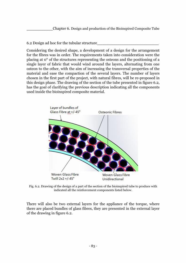
- 83 -
______________Chapter 6. Design and production of the Bioinspired Composite Tube
6.2 Design ad hoc for the tubular structure_________________________________
Considering the desired shape, a development of a design for the arrangement
for the fibres was in order. The requirements taken into consideration were the
placing at 0° of the structures representing the osteons and the positioning of a
single layer of fabric that would wind around the layers, alternating from one
osteon to the other, with the aim of increasing the transversal properties of the
material and ease the compaction of the several layers. The number of layers
chosen in the first part of the project, with natural fibres, will be re-proposed in
this design phase. The drawing of the section of the tube presented in figure 6.2,
has the goal of clarifying the previous description indicating all the components
used inside the bioinspired composite material.
Fig. 6.2. Drawing of the design of a part of the section of the bioinspired tube to produce with
indicated all the reinforcement components listed below.
There will also be two external layers for the appliance of the torque, where
there are placed bundles of glass fibres, they are presented in the external layer
of the drawing in figure 6.2.

- 84 -
______________Chapter 6. Design and production of the Bioinspired Composite Tube
6.3 Description of the components________________________________________
Once decided how to arrange the structure it becomes necessary to define the
components chosen for that arrangement. The main element that constitutes
the bioinspired composite tube, the same one used in the previous research
project [15], is the sleeve, of 2,5 mm of diameter, constituted of +/-45° carbon
fibres filled with unidirectional glass fibres. In picture 6.3, it is possible to see a
representation of what will be called from now on the osteonic fibre.
Fig. 6.3. Osteonic fibre: the rowing of Glass Fibre and the sleeve of Twill 2x2 Carbon Fibre[15].
The fibre fabric used to roll up the osteonic fibre is made of unidirectional glass
fibres placed at 90° with respect to the axis of the tube in the making. A picture
of such component is resented in figure 6.4. Another woven of glass fibre
oriented +/-45°, with respect to the axis of the tube, was used to cover the
surface of the mold in order to obtain a better finishing surface and increase the
quantity of non 0° fibre for the transversal properties.

- 85 -
______________Chapter 6. Design and production of the Bioinspired Composite Tube
Fig. 6.4. Representation of Twill 2x2 Glass Fibre Woven, on the left, and Unidirectional Glass
Fibre Woven of the right.
As far as it concerns the two external layers of fibres, necessary for the chosen
technique to provide the desired compaction of the whole structure and the
resulting “squeezing” effect, bundles of glass fibres were chosen. To the disk to
which they would be fastened, a torque would be applied and the fibres would
compact the underlying ones by been wrapped around them. In table 6.1 it is
possible to find a summary of all the components with their specific
characteristics.
Osteonic Fibre Glass Fibre Unidirectional 1,2 [g/m]
Osteonic Fibre Carbon Fibre Twill 2x2 +/-45° 3,4 [g/m]
Bundles +/-45° Glass Fibre Unidirectional 2,4 [g/m]
Internal woven Glass Fibre Unidirectional 220 [g/m^2]
Internal surface woven Glass Fibre Twill 2x2 +/-45° 300 [g/m^2]
Table 6.1. Characteristics of the reinforcement components.
The matrix used for the production of this set of tubes is the same one used for
the previous natural tubes, epoxy resin RIMR 135 and the hardener RIMH 137.
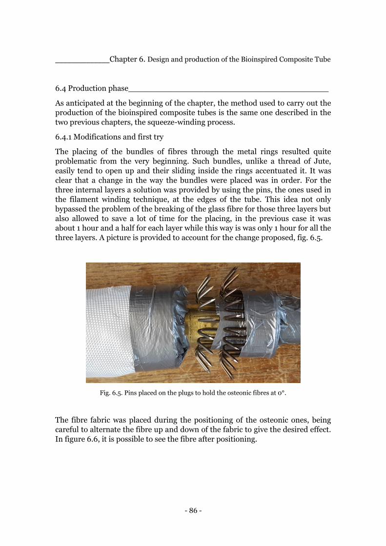
- 86 -
______________Chapter 6. Design and production of the Bioinspired Composite Tube
6.4 Production phase________________________________________
As anticipated at the beginning of the chapter, the method used to carry out the
production of the bioinspired composite tubes is the same one described in the
two previous chapters, the squeeze-winding process.
6.4.1 Modifications and first try
The placing of the bundles of fibres through the metal rings resulted quite
problematic from the very beginning. Such bundles, unlike a thread of Jute,
easily tend to open up and their sliding inside the rings accentuated it. It was
clear that a change in the way the bundles were placed was in order. For the
three internal layers a solution was provided by using the pins, the ones used in
the filament winding technique, at the edges of the tube. This idea not only
bypassed the problem of the breaking of the glass fibre for those three layers but
also allowed to save a lot of time for the placing, in the previous case it was
about 1 hour and a half for each layer while this way is was only 1 hour for all the
three layers. A picture is provided to account for the change proposed, fig. 6.5.
Fig. 6.5. Pins placed on the plugs to hold the osteonic fibres at 0°.
The fibre fabric was placed during the positioning of the osteonic ones, being
careful to alternate the fibre up and down of the fabric to give the desired effect.
In figure 6.6, it is possible to see the fibre after positioning.

- 87 -
______________Chapter 6. Design and production of the Bioinspired Composite Tube
Fig. 6.6. The osteonic fibres alternating up and down the glass fibre fabric.
The picture represents one end of the tube and, of course, the edges have been
cut after the production. The layer whose fibre resulted at +45° at the end of the
process, the ones attached to the middle disk, were placed with the original
method, so extra care was put into their positioning and it took around 2 hours
to complete it. The last layer at -45° was laid down after the impregnation of the
structure with the resin and it took around 45 minutes to complete it. The rest of
the process was carried out as described previously in the chapter about the
technique.
6.4.2 Observations and second try
The first tube produced, clearly showed in the section that it was harder than
expected to obtain the required wavy trend of the fabric around he osteonic
fibres. This was due to the fact that they could oscillate from their original
position a little bit and that the fibres from one layer could easily get together
with the ones of the layer above or below. It resulted in an alternation of the
fabric of 3 or 4 per wave. The second tube was characterized by a careful fixing
of the osteonic fibres at the edges with a round of tape per layer. The rest of the
process was performed in the same manner as the previous tube. In the picture
below, figure 6.7, it is possible to see a portion of the section of the first tube
while the second one is not reported because it looks exactly as the first one.

- 88 -
______________Chapter 6. Design and production of the Bioinspired Composite Tube
Fig. 6.7. Portion of the section of the first bioinspired composite tube.
6.5 Comparative tubes___________________________________________________
Comparative tubes are necessary to evaluate the effectiveness of the bioinspired
internal structure. In order to be comparable they have to present the same type
of fibres, carbon and glass, and in the same quantities.
6.5.1 Design of the comparative structure
A careful design was in order to guarantee the conditions above-mentioned. The
carbon fibre sleeves have been replaced with the same quantity of carbon fibre
but in the form of carbon plain woven with the fibre placed at +/-45°. The
unidirectional glass fibres contained in the carbon sleeves have been replaced
with bundles of fibre in the same quantity. In the table below it is possible to
have a summary of the components of the comparative structure.
Bundles 0° Glass Fibre Unidirectional 1,2 [g/m]
Carbor Fibre woven Carbon Fibre Plain +/-45° 600 [g/m^2]
Bundels +/-45° Glass Fibre Unidirectional 2,4 [g/m]
Internal woven Glass Fibre Unidirectional 220 [g/m^2]
Internal surface woven Glass Fibre Twill 2x2 +/-45° 300 [g/m^2] Table 6.2 Schematic summary of the comparative structure components.
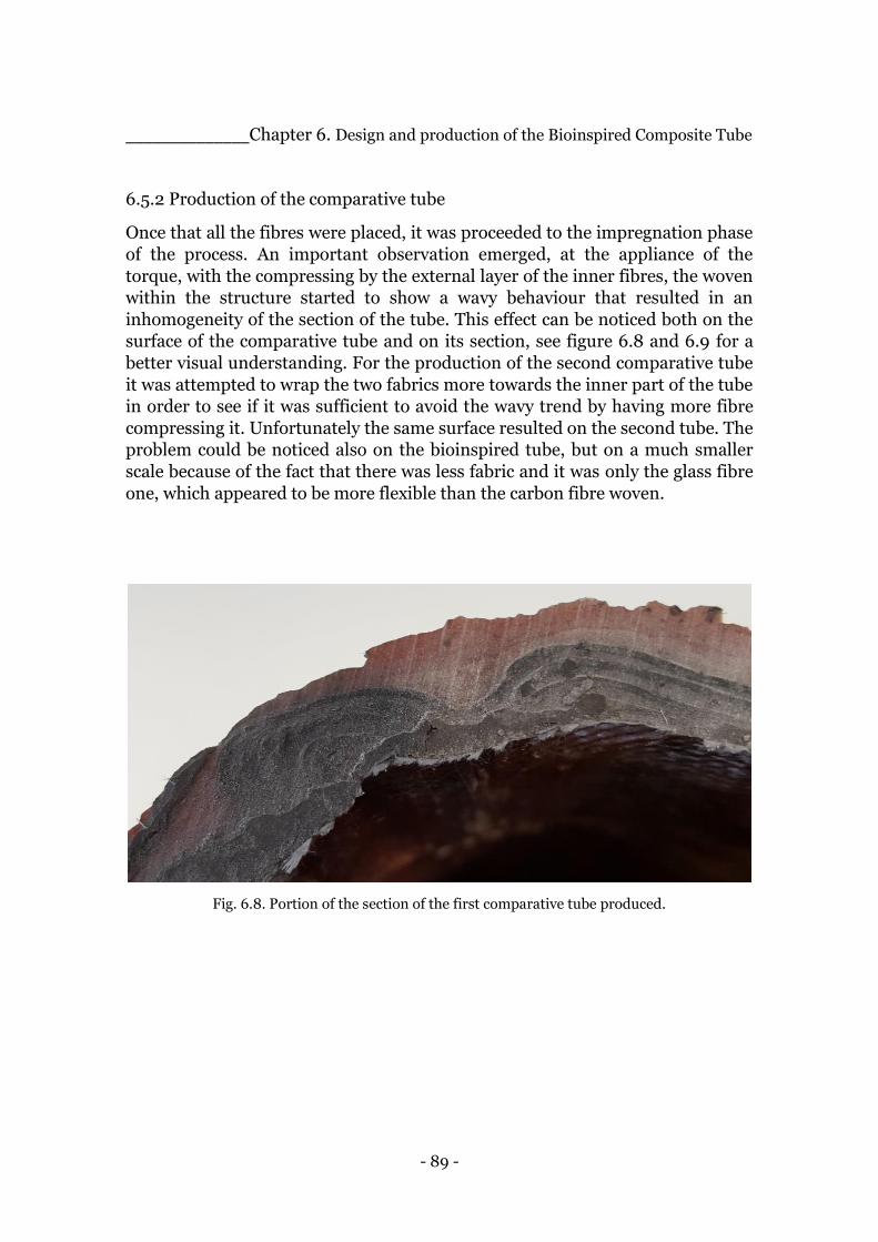
- 89 -
______________Chapter 6. Design and production of the Bioinspired Composite Tube
6.5.2 Production of the comparative tube
Once that all the fibres were placed, it was proceeded to the impregnation phase
of the process. An important observation emerged, at the appliance of the
torque, with the compressing by the external layer of the inner fibres, the woven
within the structure started to show a wavy behaviour that resulted in an
inhomogeneity of the section of the tube. This effect can be noticed both on the
surface of the comparative tube and on its section, see figure 6.8 and 6.9 for a
better visual understanding. For the production of the second comparative tube
it was attempted to wrap the two fabrics more towards the inner part of the tube
in order to see if it was sufficient to avoid the wavy trend by having more fibre
compressing it. Unfortunately the same surface resulted on the second tube. The
problem could be noticed also on the bioinspired tube, but on a much smaller
scale because of the fact that there was less fabric and it was only the glass fibre
one, which appeared to be more flexible than the carbon fibre woven.
Fig. 6.8. Portion of the section of the first comparative tube produced.
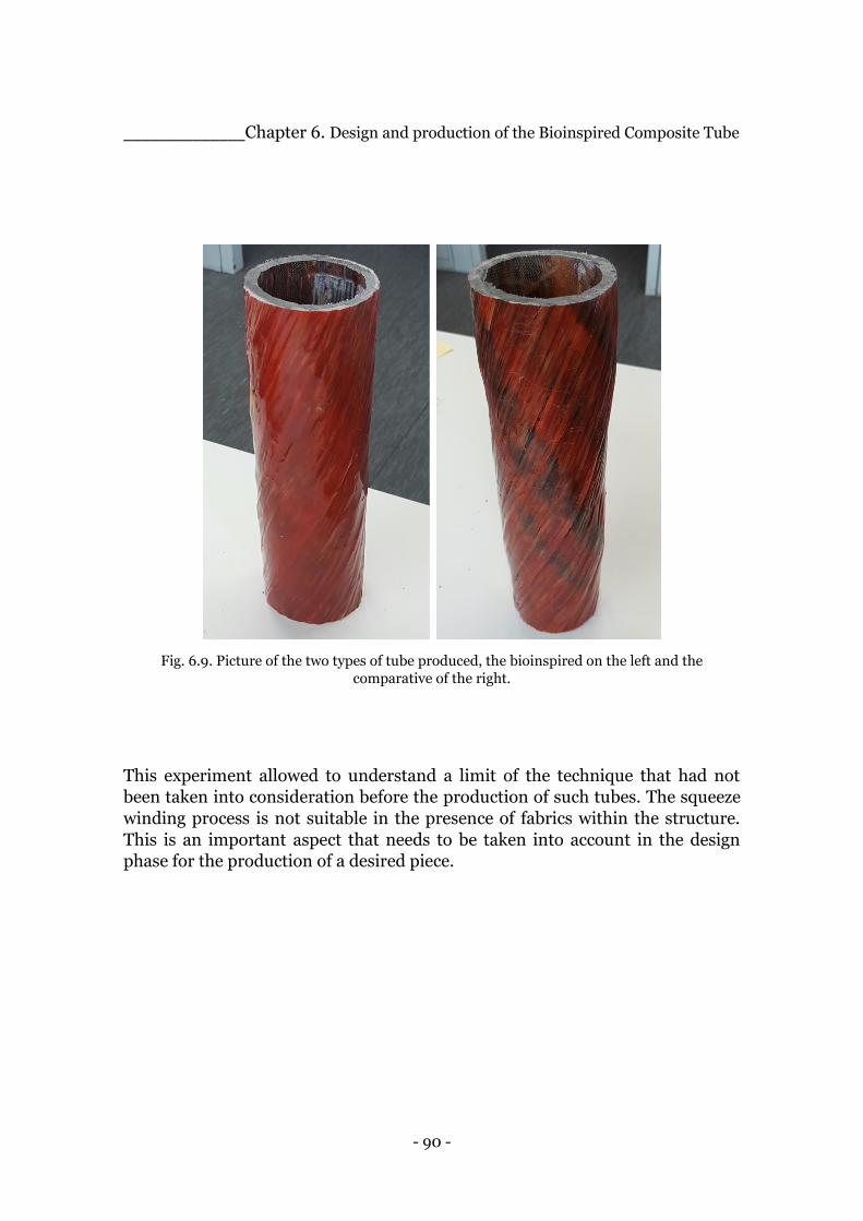
- 90 -
______________Chapter 6. Design and production of the Bioinspired Composite Tube
Fig. 6.9. Picture of the two types of tube produced, the bioinspired on the left and the
comparative of the right.
This experiment allowed to understand a limit of the technique that had not
been taken into consideration before the production of such tubes. The squeeze
winding process is not suitable in the presence of fabrics within the structure.
This is an important aspect that needs to be taken into account in the design
phase for the production of a desired piece.
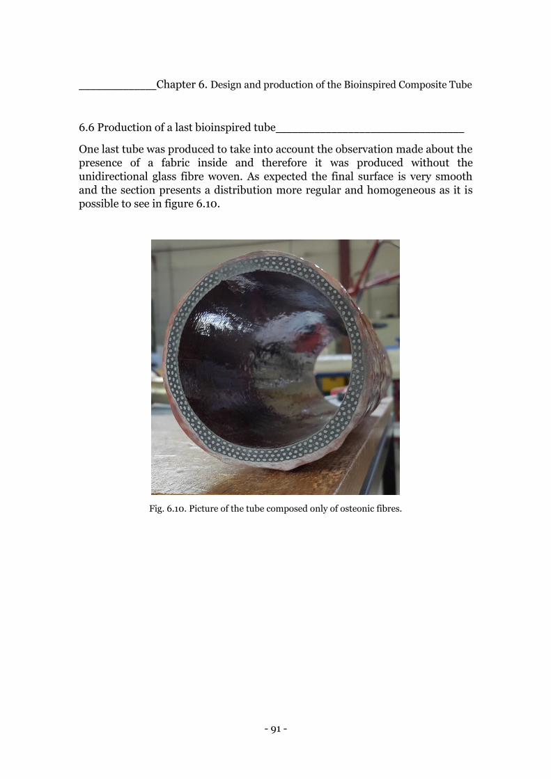
- 91 -
______________Chapter 6. Design and production of the Bioinspired Composite Tube
6.6 Production of a last bioinspired tube__________________________________
One last tube was produced to take into account the observation made about the
presence of a fabric inside and therefore it was produced without the
unidirectional glass fibre woven. As expected the final surface is very smooth
and the section presents a distribution more regular and homogeneous as it is
possible to see in figure 6.10.
Fig. 6.10. Picture of the tube composed only of osteonic fibres.
- 92 -
Chapter 7.
Characterization of the
Artificial Fibre Composite Materials _______________________________________________________________________
_______________________________________________________________________
The production phase of the second part of the project permitted to obtain a
total of 5 tubes, two of them presented the internal structure characterized by
the presence of the so called Osteonic fibres and a glass fibre woven wound
around them. Two other tubes, called comparative, were manufactured with
simple glass fibre bundles and a carbon fabric thought to provide for carbon
component in the bioinspired tube. One last tube only with Osteonic fibres and
no fabric was created in order to test an observation that presented during the
production of the other four tubes. Once produced, a characterization of the
second set of tubes was in order. The tests were performed with the testing
machine available at the Institute of Polymer Materials and Plastic Engineering.
A further investigation was carried out evaluating the fibre volume content of all
the samples extracted from the tubes, this gave the possibility to propose more
accurate considerations basing them on the two parameters and comparisons
between the values of the different tubes, especially the ones with a different
internal structure. This part of the process which constitute the last practical
experience is fundamental to recollect of the concepts and deliver the final
outcomes of the project and it will be described throughout this chapter.
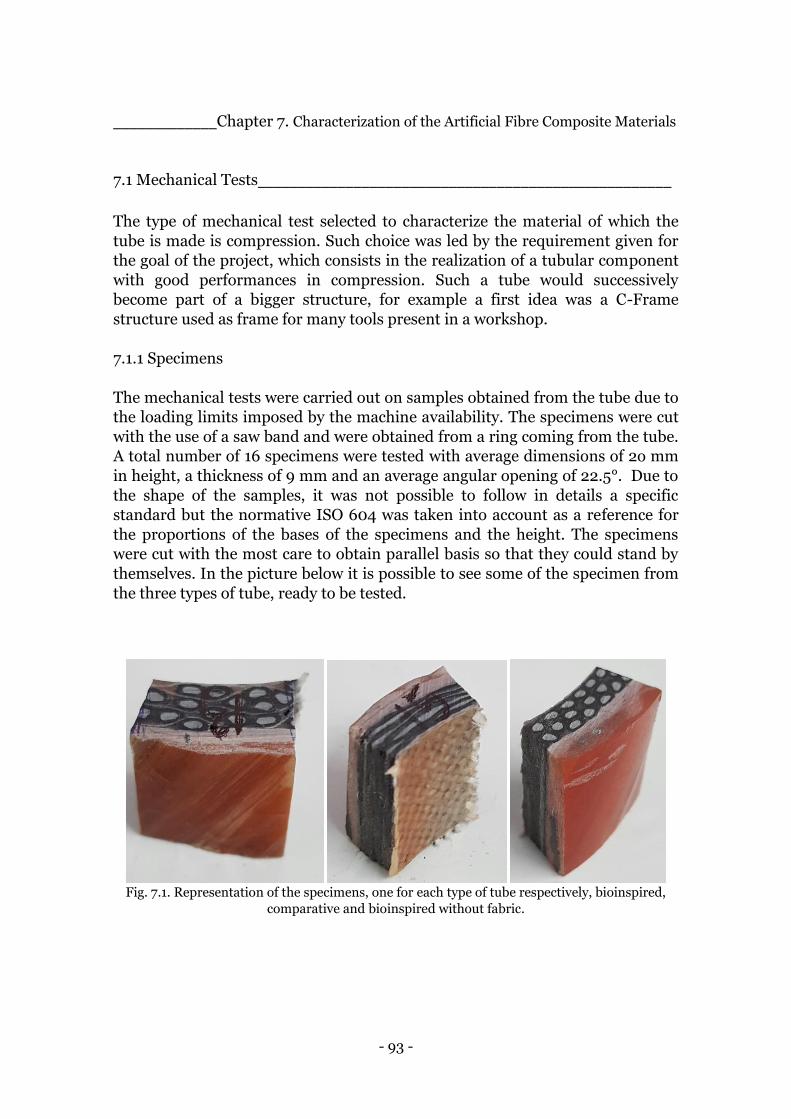
- 93 -
_____________Chapter 7. Characterization of the Artificial Fibre Composite Materials
7.1 Mechanical Tests____________________________________________________
The type of mechanical test selected to characterize the material of which the
tube is made is compression. Such choice was led by the requirement given for
the goal of the project, which consists in the realization of a tubular component
with good performances in compression. Such a tube would successively
become part of a bigger structure, for example a first idea was a C-Frame
structure used as frame for many tools present in a workshop.
7.1.1 Specimens
The mechanical tests were carried out on samples obtained from the tube due to
the loading limits imposed by the machine availability. The specimens were cut
with the use of a saw band and were obtained from a ring coming from the tube.
A total number of 16 specimens were tested with average dimensions of 2o mm
in height, a thickness of 9 mm and an average angular opening of 22.5°. Due to
the shape of the samples, it was not possible to follow in details a specific
standard but the normative ISO 604 was taken into account as a reference for
the proportions of the bases of the specimens and the height. The specimens
were cut with the most care to obtain parallel basis so that they could stand by
themselves. In the picture below it is possible to see some of the specimen from
the three types of tube, ready to be tested.
Fig. 7.1. Representation of the specimens, one for each type of tube respectively, bioinspired,
comparative and bioinspired without fabric.
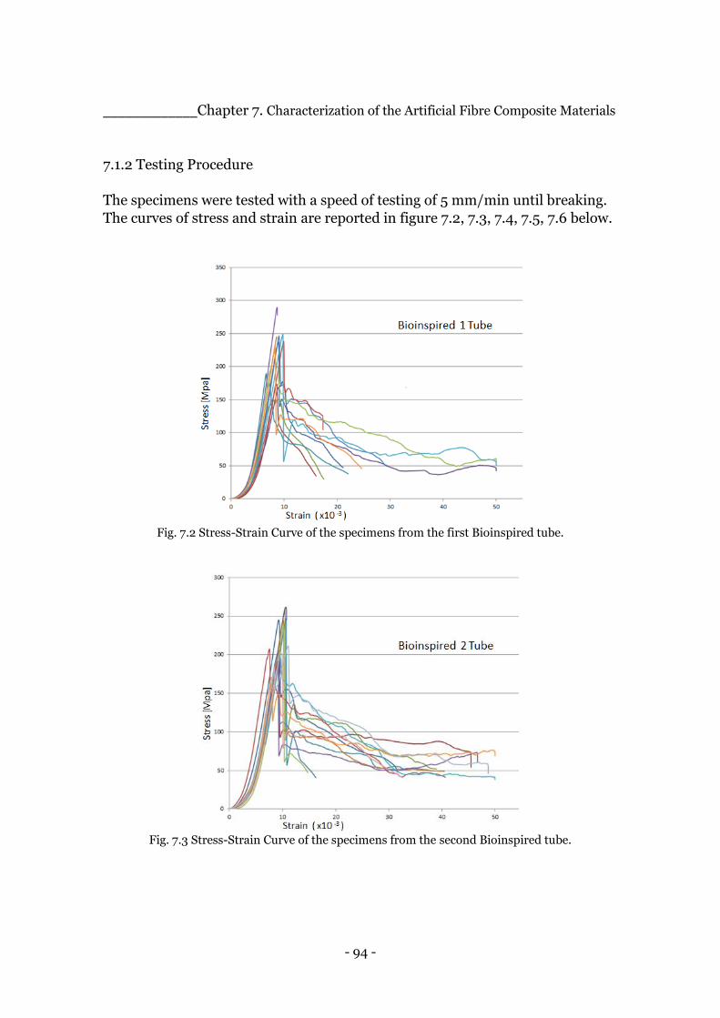
- 94 -
_____________Chapter 7. Characterization of the Artificial Fibre Composite Materials
7.1.2 Testing Procedure
The specimens were tested with a speed of testing of 5 mm/min until breaking.
The curves of stress and strain are reported in figure 7.2, 7.3, 7.4, 7.5, 7.6 below.
Fig. 7.2 Stress-Strain Curve of the specimens from the first Bioinspired tube.
Fig. 7.3 Stress-Strain Curve of the specimens from the second Bioinspired tube.
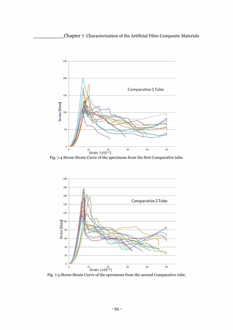
- 95 -
_____________Chapter 7. Characterization of the Artificial Fibre Composite Materials
Fig. 7.4 Stress-Strain Curve of the specimens from the first Comparative tube.
Fig. 7.5 Stress-Strain Curve of the specimens from the second Comparative tube.
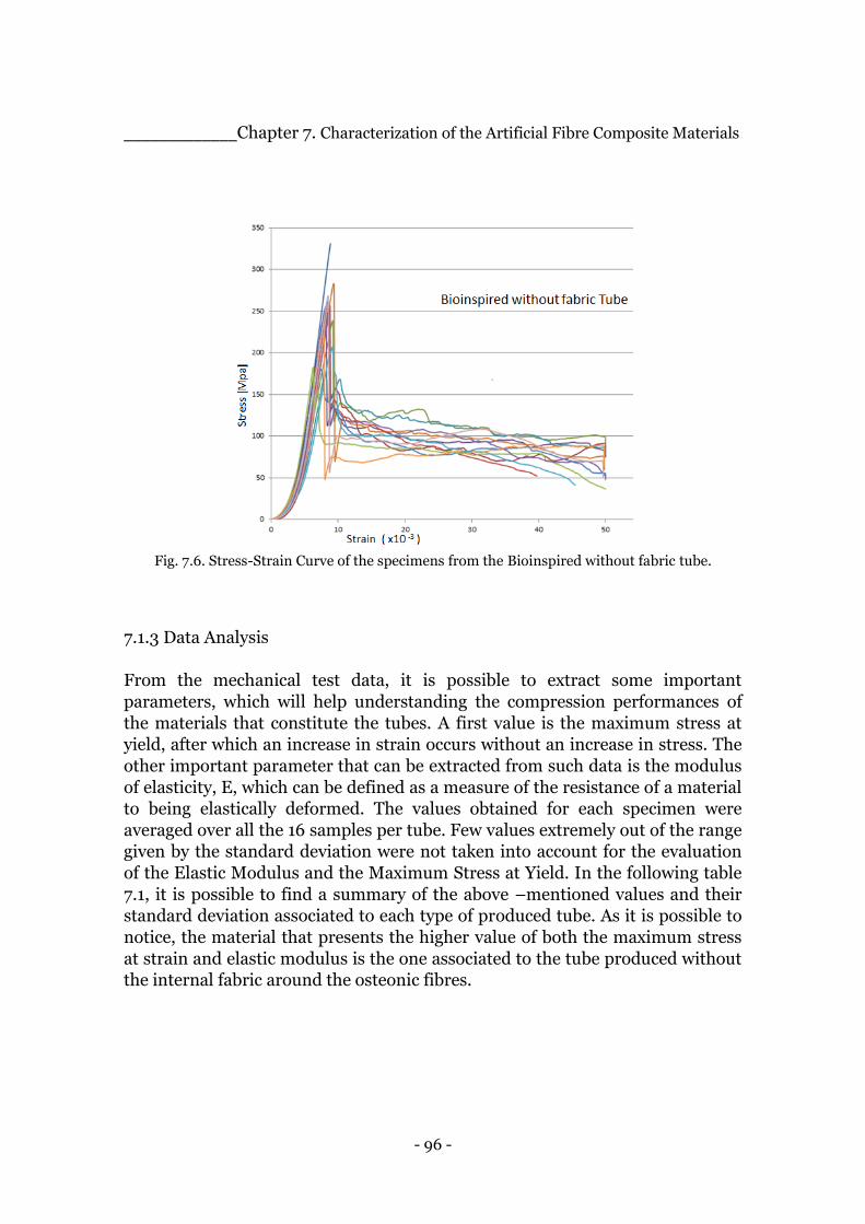
- 96 -
_____________Chapter 7. Characterization of the Artificial Fibre Composite Materials
Fig. 7.6. Stress-Strain Curve of the specimens from the Bioinspired without fabric tube.
7.1.3 Data Analysis
From the mechanical test data, it is possible to extract some important
parameters, which will help understanding the compression performances of
the materials that constitute the tubes. A first value is the maximum stress at
yield, after which an increase in strain occurs without an increase in stress. The
other important parameter that can be extracted from such data is the modulus
of elasticity, E, which can be defined as a measure of the resistance of a material
to being elastically deformed. The values obtained for each specimen were
averaged over all the 16 samples per tube. Few values extremely out of the range
given by the standard deviation were not taken into account for the evaluation
of the Elastic Modulus and the Maximum Stress at Yield. In the following table
7.1, it is possible to find a summary of the above –mentioned values and their
standard deviation associated to each type of produced tube. As it is possible to
notice, the material that presents the higher value of both the maximum stress
at strain and elastic modulus is the one associated to the tube produced without
the internal fabric around the osteonic fibres.

- 97 -
_____________Chapter 7. Characterization of the Artificial Fibre Composite Materials
Tube’s Material σmax [MPa] StanDev σmax E [MPa] StanDev E
Bioinspired 1 222,92 44,88 43082,12 8591,63
Bioinspired 2 213,18 32,95 41111,7 3908,74
Comparative 1 143,25 40,4 30844,15 5925
Comparative 2 137,31 30,68 29501,73 6000,69
Bioinspired noFabric 234,42 45,22 50066,14 7447,34 Table 7.1 Summary of the Compression Properties associated to the materials composing the
produced tubes.
Some pictures of the samples after the compression tests can be provided and it
is possible to observe that they broke in different manners.
Fig. 7.7. Some of the specimens after the compression test.
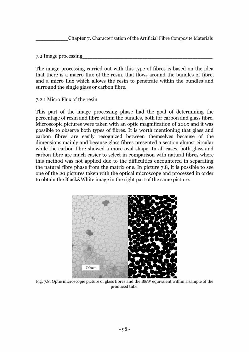
- 98 -
_____________Chapter 7. Characterization of the Artificial Fibre Composite Materials
7.2 Image processing____________________________________________________
The image processing carried out with this type of fibres is based on the idea
that there is a macro flux of the resin, that flows around the bundles of fibre,
and a micro flux which allows the resin to penetrate within the bundles and
surround the single glass or carbon fibre.
7.2.1 Micro Flux of the resin
This part of the image processing phase had the goal of determining the
percentage of resin and fibre within the bundles, both for carbon and glass fibre.
Microscopic pictures were taken with an optic magnification of 200x and it was
possible to observe both types of fibres. It is worth mentioning that glass and
carbon fibres are easily recognized between themselves because of the
dimensions mainly and because glass fibres presented a section almost circular
while the carbon fibre showed a more oval shape. In all cases, both glass and
carbon fibre are much easier to select in comparison with natural fibres where
this method was not applied due to the difficulties encountered in separating
the natural fibre phase from the matrix one. In picture 7.8, it is possible to see
one of the 20 pictures taken with the optical microscope and processed in order
to obtain the Black&White image in the right part of the same picture.
Fig. 7.8. Optic microscopic picture of glass fibres and the B&W equivalent within a sample of the
produced tube.
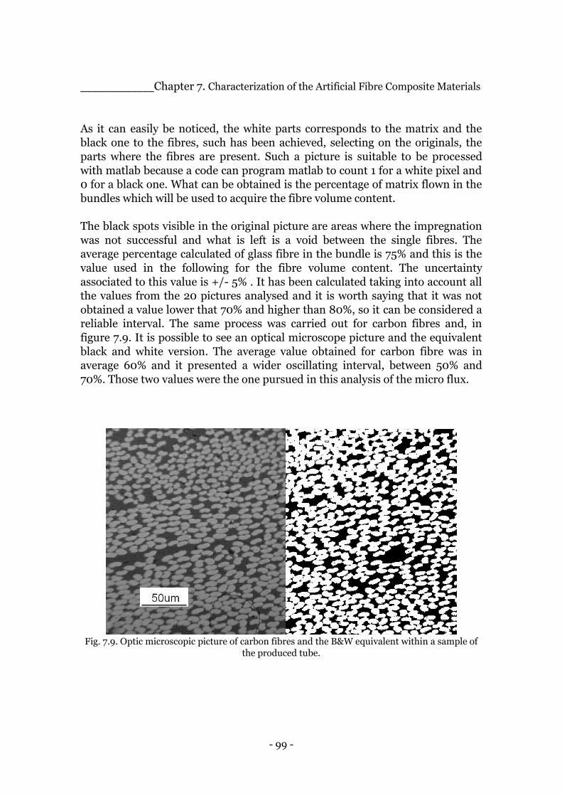
- 99 -
_____________Chapter 7. Characterization of the Artificial Fibre Composite Materials
As it can easily be noticed, the white parts corresponds to the matrix and the
black one to the fibres, such has been achieved, selecting on the originals, the
parts where the fibres are present. Such a picture is suitable to be processed
with matlab because a code can program matlab to count 1 for a white pixel and
0 for a black one. What can be obtained is the percentage of matrix flown in the
bundles which will be used to acquire the fibre volume content.
The black spots visible in the original picture are areas where the impregnation
was not successful and what is left is a void between the single fibres. The
average percentage calculated of glass fibre in the bundle is 75% and this is the
value used in the following for the fibre volume content. The uncertainty
associated to this value is +/- 5% . It has been calculated taking into account all
the values from the 20 pictures analysed and it is worth saying that it was not
obtained a value lower that 70% and higher than 80%, so it can be considered a
reliable interval. The same process was carried out for carbon fibres and, in
figure 7.9. It is possible to see an optical microscope picture and the equivalent
black and white version. The average value obtained for carbon fibre was in
average 60% and it presented a wider oscillating interval, between 50% and
70%. Those two values were the one pursued in this analysis of the micro flux.
Fig. 7.9. Optic microscopic picture of carbon fibres and the B&W equivalent within a sample of
the produced tube.
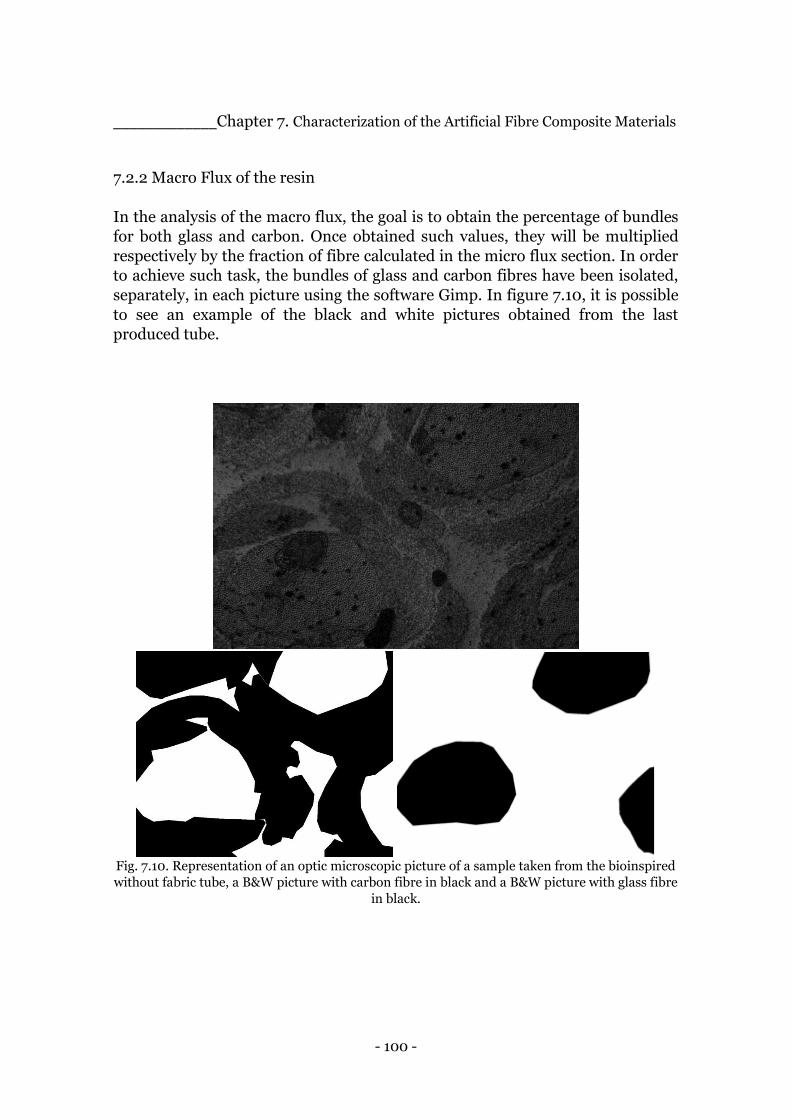
- 100 -
_____________Chapter 7. Characterization of the Artificial Fibre Composite Materials
7.2.2 Macro Flux of the resin
In the analysis of the macro flux, the goal is to obtain the percentage of bundles
for both glass and carbon. Once obtained such values, they will be multiplied
respectively by the fraction of fibre calculated in the micro flux section. In order
to achieve such task, the bundles of glass and carbon fibres have been isolated,
separately, in each picture using the software Gimp. In figure 7.10, it is possible
to see an example of the black and white pictures obtained from the last
produced tube.
Fig. 7.10. Representation of an optic microscopic picture of a sample taken from the bioinspired
without fabric tube, a B&W picture with carbon fibre in black and a B&W picture with glass fibre
in black.
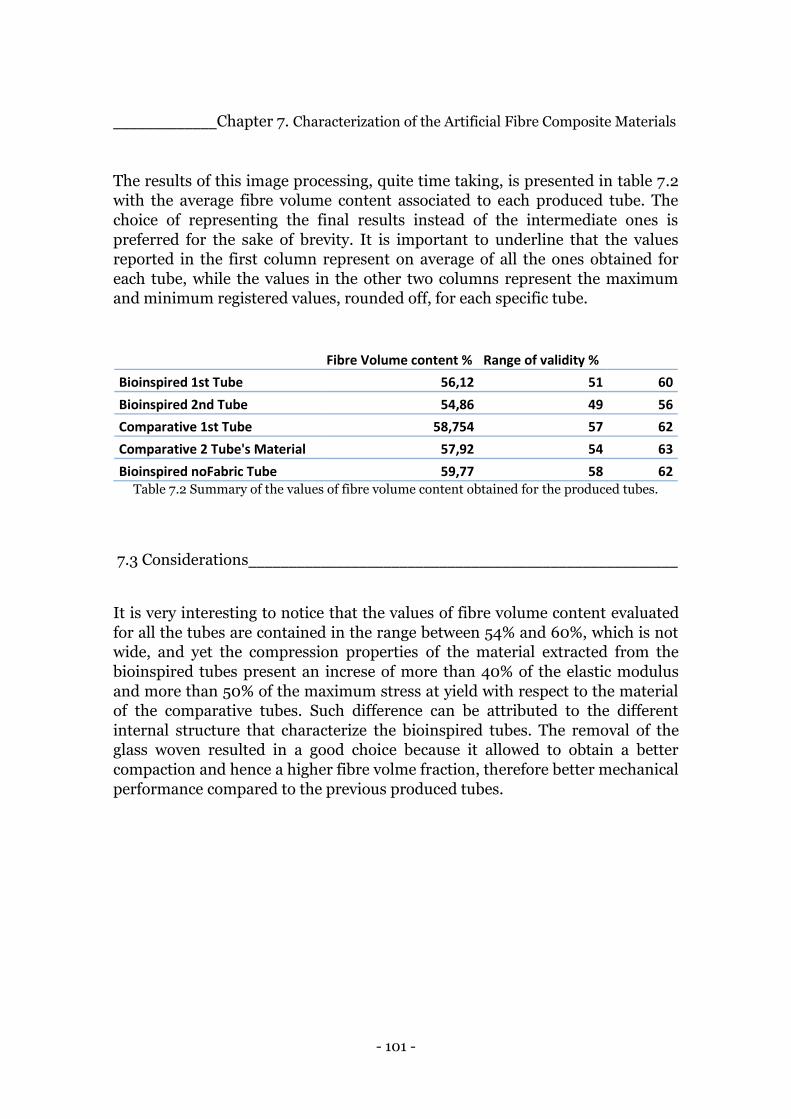
- 101 -
_____________Chapter 7. Characterization of the Artificial Fibre Composite Materials
The results of this image processing, quite time taking, is presented in table 7.2
with the average fibre volume content associated to each produced tube. The
choice of representing the final results instead of the intermediate ones is
preferred for the sake of brevity. It is important to underline that the values
reported in the first column represent on average of all the ones obtained for
each tube, while the values in the other two columns represent the maximum
and minimum registered values, rounded off, for each specific tube.
Fibre Volume content % Range of validity %
Bioinspired 1st Tube 56,12 51 60
Bioinspired 2nd Tube 54,86 49 56
Comparative 1st Tube 58,754 57 62
Comparative 2 Tube's Material 57,92 54 63
Bioinspired noFabric Tube 59,77 58 62 Table 7.2 Summary of the values of fibre volume content obtained for the produced tubes.
7.3 Considerations______________________________________________________
It is very interesting to notice that the values of fibre volume content evaluated
for all the tubes are contained in the range between 54% and 60%, which is not
wide, and yet the compression properties of the material extracted from the
bioinspired tubes present an increse of more than 40% of the elastic modulus
and more than 50% of the maximum stress at yield with respect to the material
of the comparative tubes. Such difference can be attributed to the different
internal structure that characterize the bioinspired tubes. The removal of the
glass woven resulted in a good choice because it allowed to obtain a better
compaction and hence a higher fibre volme fraction, therefore better mechanical
performance compared to the previous produced tubes.
- 102 -
Chapter 8.
Conclusions and Outlook _______________________________________________________________________
_______________________________________________________________________
The project started with the aim of manufacturing a composite tube that could
provide good compression performances useful to be included as component for
the creation of a more complex frame, common for several tools present in a
workshop. This work is on a research level and constitutes a first step in the
realization of such structure. The internal arrangement of fibres chosen in the
design phase derives from previous projects conducted in the Mechanical
Department of Politecnico di Milano. The work carried out during the eight
moths spent in the Institute of Polymer Materials and Plastic Technology based
in Clausthal-Zellerfeld, has been composed of two main parts: the first one was
focused on developing the manufacturing technique that could permit to fulfil
certain requirements; the second one has been characterized by the
arrangement of the internal design and components, the production and the
characterization of the material of which the tubes were constituted. Interesting
results have emerged from both parts of the project. As far as it concerns the
manufacturing technique, the Squeeze-Winding process, it has been possible to
produce tubes that presented an increase in the fibre volume content, using
natural fibres ,of more than 30 % compared to the tubes produced with the well-
known Filament-Winding technique. Such difference affected the mechanical
properties of the material constituting the produced tubes, which showed an
increase of the maximum stress and the elastic modulus of both around 20%.
The squeeze-winding technique did not allow, with natural fibres, to obtain the
desired fibre volume content of 60% which is the typical value of bone material.
This was attributed to the tendency of natural fibres to relax when put under
tension. The manufacturing process was therefore applied to the designed
bioinspired arrangement of glass and carbon fibres. This phase of the project
resulted with the production of 5 tubes, two bioinspired ones, two comparative
ones and one bioinspired tube without the internal glass fibre woven.

- 103 -
_______________________________________Chapter 8. Conclusions and Outlook
The range of fibre volume content for all the tubes produced, resulted between
54% and 60%, the one with the higher average fibre volume content was the last
one produced without the fabric. This was a confirmation that the squeeze
winding process gives better results if no fabric placed inside, as it appeared
clear by observing the final external surface of the comparative tubes which
presented a wavy trend due to the compaction of the fibre fabric. The
demonstration of the effectiveness of the Osteonic internal arrangement came
from the compression tests performed on specimens extracted from the tubes.
The material from the Bioinspired tube with no fabric inside, showed an elastic
modulus almost double than the material from the comparative tubes even
though the fibre volume content resulted differing only few points percentage.
Successive steps suggested to continue this line of research may start from the
testing of the tubes regarding their integrity. This might lead to a better
characterization of the tubes. In fact, since only specimen from them were
tested, some differences in the mechanical behaviour might, for example, be
expected due to the fact that cutting the tubes longitudinally lead to an
inevitable breaking of the thin fibre tubes that aimed to mimic the osteons of the
cortical bone, leading to an embrittlement of the material on the sides. In
addition, it can be underlined that the width was kept small, almost the same
dimension of the thickness of the tube, in order to have an almost square
surface. Evaluation of the Kic and toughening mechanisms could be interesting.
Another interesting aspect would be to find a way to combine the squeezing part
of the developed technique with the appliance of vacuum, to reduce the number
of air entrapments present in the final product. A future line of research should
build such frame with the described tubes as components and evaluate the
maximum load that it would be able to sustain.
Fig. 8.1. A comparison between a representation of the osteonic structure of cortical bone and
the internal arrangement of fibre in the produced tube.
- 104 -
Bibliography
_______________________________________________________________________
_______________________________________________________________________
[1] André R. Studart, Towards High-Performance Bioinspired Composites, Advanced
Materials, 2012.
[2] Markus Milwich, Thomas Speck, Olga Speck, Thomas Stegmaier and Heinrich
Planck, Biomimetics and Technical Textiles: Solving Engineering problems with the
help of nature’s wisdom, American Journal of Botany, 2006.
[3] Bharat Bhushan, Biomimetics: Lesson from nature – An overview, Philosophical
Transaction of the Royal Society, 2009.
[4] Julian F. V. Vincent, Olga A. Bogatyreva, Nikolaj R. Bogatyrev, Adrian Bowyer and
Anja-Karina Pahl, Biomimetics: its practice and theory, Journal of the Royal Society,
2006.
[5] Horacio D. Espinosa, Jee E. Rim, Francois Barthlat, Markus J. Buehler, Merge of
structure and material in nacre and bone – Perspectives on de novo biomimetic
materials, Progress in Material Science, 2009.
[6] Peter Fratzl, Biomimetic materials research: What can we really learn from nature’s
structural materials?, Journal of the Royal Society, 2007.
[7] Hideki Kakisawa and Taro Sumitomo, The toughening mechanism of nacre and the
structural materials inspired by nacre, Science and Technology of Advanced Materials,
2012.
[8] Sinan Keten, Zhiping Xu, Britni Ihle and Markus J. Buehler, Nanoconfinement
controls stiffness, strength and mechanical toughness of β-sheet crystals in silk, Nature
Materials, 2010.
[9] Tom Masselter and Thomas Speck, Biomimetic Fiber Reinforced Compounds
Materials, Plant Biomimetics Group Freiburg, University of Freiburg, Germany
- 105 -
[10] M. F. Ashby, L. J. Gibson, U. Weigst and J. Olive, The mechanical properties of
natural materials. I. Material property charts. Royal Society Publishing.
[11] L. J. Gibson,M. F. Ashby, G.N. Karam, U. Wegst and H. R. Shercliff, The
mechanical properties of natural materials. II. Microstructure for mechanical
efficiency. Royal Society Publishing.
[12] John D. Currey, The structure and mechanics of bone. Journal of material science,
2011.
[13] F. Libonati, C. Colombo and L. Vergani, Design and characterization of a
biomimetic composite inspired to human bone. Fatigue & Fracture of Engineering
Materials & Structures, 2014.
[14] A. Panizio, Struttura Bionica in Materiale Composito, Master Thesis, 2012.
[15] F. Ielmini, Design, Manufacturing and Testing of a Composite Material Inspired to
Bone Microstructure, Master Thesis, 2015.
[16] J. B. Phelps, G. B. Hubbard, X. Wang, C. M. Agrawal, Microstructural
heterogeneity and the fracture toughness of bone, 2000.
[17] P.K. Mallik, Fiber-Reinforced Composite, Materials, Manufacturing and Design,
Third edition, 2007.
[18] http://www.slideshare.net/ratnachatterjee/advanced-future-applications-of-
composite-fibres-in-the-automotive-industry
[19] http://www.nuplex.com/composites/processes
[20] http://www.technologystudent.com/prddes1/biomimetic1.html
[21] International Standard ISO 604- Plastics, Determination of Compressive
Properties, Third Edition, 2002.
[22] F. H. Abdalla, S. A. Mutasher, Y.A. Khalid, S. M. Sapuan, A. M. S. Hamouda, B.B.
Sahari, M. M. Hamdan, Design and fabrication of low cost filament winding machine.
Elsevier, Material & Design, 2007.
[23] Paivi Lehtiniemi, Kari Dufva, Tommi Berg, Mikael Skrifvars and Pentti Jarvela,
Natural fibre-based reinforcements in epoxy composites processed by filament
winding.Reinforced Plastcis & Composites, 2011.
[24] Frank C.Shen, A filament-wound structure technology overview. Materials,
Chemistry and Phsics, 1995.
[25] David Cohen, Susan C. Mantell, Liyang Zhao, The effect of fibre volume fraction of
filament wound composite pressure vessel strength. Elsevier, Composites, 2001.
- 106 -
[26] P.Mertiny, F. Ellyin, Influence of the filament winding tension on physical and
mechanical properties of reinforced composites. Elsevier, Composites, Applied Science
and manufacturing, 2002.
[27] M. Munro, Review of Manufacturing of Fibre Composite Components by Filament
Winding. Polymer Composites, 1988.
[28] http://www.technologystudent.com/prddes1/biomimetic1.html
[29] Werner Hufenbach, Wojciech Brazejewski, Lothar Kroll, Robert Bohm, Maik
Gude, Andrzej Czulak, Manufacture and multiaxial test o composite tube specimens
with braided glass fibre reinforcements. Journal of Materials Processing and
Technology, 2005
[30] R. S. Trask and I. P. Bond, Biomimetic self-healing of advanced composite
structures using hollow glass fibres. Smart Materials and structures, 2006.
[31] Chang-an Wang, Yong Huang, Qingfeng Zan, Hai Guo, Shengyou Cai, Biomimetic
Structure design – A possible approach to change the brittleness of ceramics in nature.
Materials Science & Engineering, 2000.
[32] P. Potluri, A. Manan, M. Francke, R. J. Day, Flexural and torsion behaviour of
biaxial and triaxial braided composite structures. Composite structures, 2006.
[33] G. Cicala, G. Cristaldi, G. Recca, G. Ziegman, A. El-Sabbagh, M. Dickert, Properties
and performances of various hybrid glass/natural fibre composites for curved pipes.
Elsevier, Material and Design, 2008.
[34] Characterization of the draping Behaviour of jute woven Fabrics for applications of
natural-fibre/epoxy composites. Journal of Appled Polymer Science, 2013.
[35] A. Alavudeen, M. Thiruchitrambalam, N. Venkateshwaran and A. Athijayamani.
Review of natural fibre reinforced woven composite, Advanced Materials, 2011.
[36] Y. Abdin, I. Taha, A. El-Sabbgh, S. Ebeid, Description of draping behaviour of
woven fabric over single curvatures by image processing and simulation techniques.
Elsievier, Composites, 2012
[37] J. B. Phelps, G. B. Hubbard, X. Wang, C. M. Agrawal, Microstructure heterogeneity
and the fracture toughness of bone. Health science Center at San Antonio, Texas,
2000.
[38] E. A. Zimmermann, M. E. Launey, H. D. Barth, R. O. Ritchie, Mixed- mode
fracture of human cortical bone, Biomaterials, 2009.
[39] R.B. Martin and D. B. Burr, Structure, Function and Adaptation of compact bone.
1989.
[40] Simin Li, Adel Abdel-Wahab and Vadim V. Silberschimidt, Analysis of fracture
processes in cortical bone tissue. Loughborohgh University, Elsevier, 2013.

- 107 -
Acknowledgements _______________________________________________________________________
_______________________________________________________________________
I would like to start thanking Professor Vergani and Dott. Libonati for the
possibility to take part in this research project and their support during the
whole experience. It has been very important for me, both because I learnt more
about this scientific field and because it helped me to understand the
characteristics that I loved the most about engineering research. Deep gratitude
to Professor Ziegmann who gave me a warm welcome to the Institute of Polymer
and Polymer technology and who has always proven to be interested in his
students and their well-being. A special thank you to Ing. Randolf Hoffmann
who has been my guide for the eight months spent in Germany, a researcher
who transmitted me great passion about science and from whom I learnt a lot.
A sincere thank you to the people I met during my journeys, both in the
personal and academic life. A dearest friend since the very beginning of this
Polimi adventure, Laura R. and her welcoming family, with me every time I was
weak. Friends met at CDS who made it a home, in particular Louis, Alessandro,
Prisca and Farzan. A companion, at first, of university’s pains and joys and now
a dear life friend, Dimitrios. To Cecilia, a friend that makes coming back to
Milano like going a bit home. To new friends who I feel like I have known them
for a long time, Laura M. and Greg and to all the people that I shared a path of
life with and had the ability to deeply touch me with their thoughts and care.
To the new member of my family, Gildo, I want to transmit my deepest
gratitude for always been there with his warm support and positive attitude.
To my mother and my sister, I have no words to tell you the strength, the
support and inspiration you both have been giving me during these years.
To all of you, my deepest and warm thank you!!!