Embed Size (px)
Citation preview

This document is not an API Standard; it is under consideration within an API technical committee but has not received all approvals re-quired to become an API Standard. It shall not be reproduced or circulated or quoted, in whole or in part, outside of API committee activities except with the approval of the Chairman of the committee having jurisdiction and staff of the API Standards Dept. Copyright API. All rights
reserved.
1
Design and Operation of Subsea Production Systems―General Requirements and Recommendations API RECOMMENDED PRACTICE 17A SIXTH EDITION, XXXX 2022
2 API RECOMMENDED PRACTICE 17A This document is not an API Standard; it is under consideration within an API technical committee but has not received all approvals re-
quired to become an API Standard. It shall not be reproduced or circulated or quoted, in whole or in part, outside of API committee activities except with the approval of the Chairman of the committee having jurisdiction and staff of the API Standards Dept. Copyright API. All rights
reserved. Design and Operation of Subsea Production Systems―General Requirements
and Recommendations
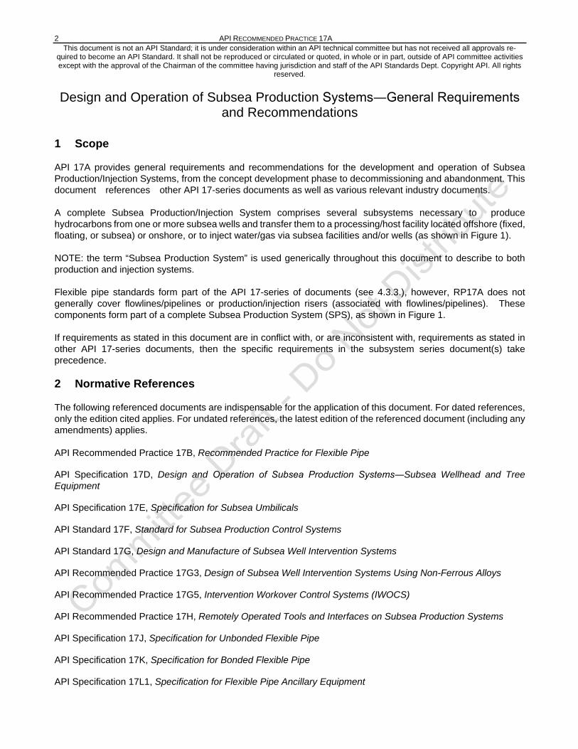
1 Scope
API 17A provides general requirements and recommendations for the development and operation of Subsea Production/Injection Systems, from the concept development phase to decommissioning and abandonment. This document references other API 17-series documents as well as various relevant industry documents.
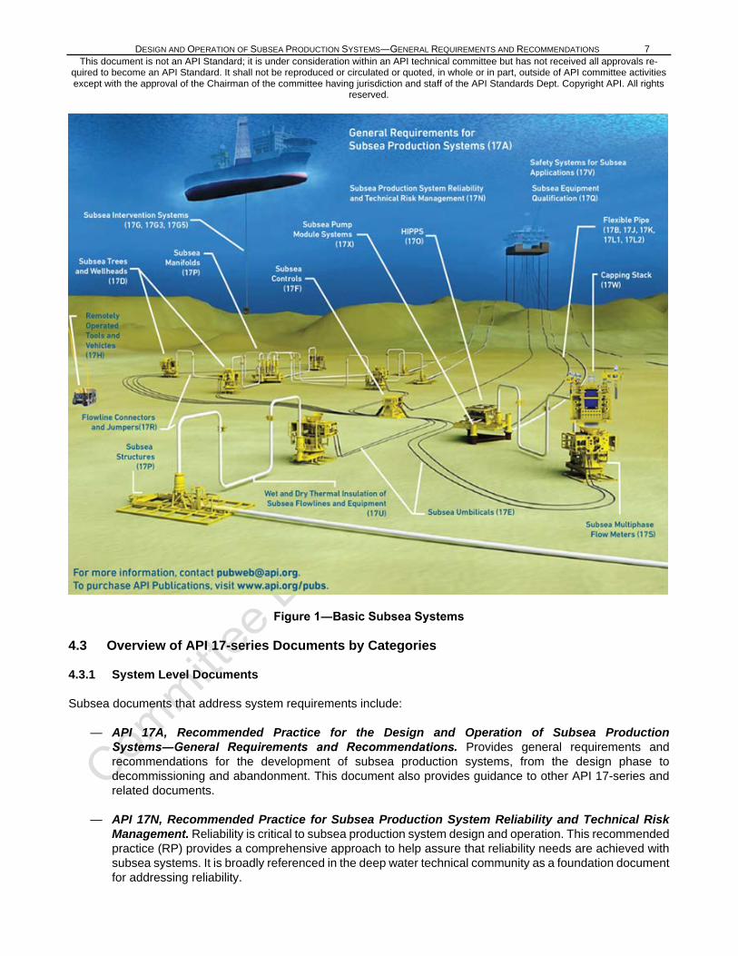
A complete Subsea Production/Injection System comprises several subsystems necessary to produce hydrocarbons from one or more subsea wells and transfer them to a processing/host facility located offshore (fixed, floating, or subsea) or onshore, or to inject water/gas via subsea facilities and/or wells (as shown in Figure 1).
NOTE: the term “Subsea Production System” is used generically throughout this document to describe to both production and injection systems.
Flexible pipe standards form part of the API 17-series of documents (see 4.3.3.), however, RP17A does not generally cover flowlines/pipelines or production/injection risers (associated with flowlines/pipelines). These components form part of a complete Subsea Production System (SPS), as shown in Figure 1.
If requirements as stated in this document are in conflict with, or are inconsistent with, requirements as stated in other API 17-series documents, then the specific requirements in the subsystem series document(s) take precedence.
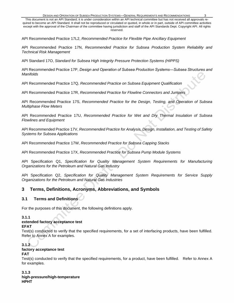
2 Normative References
The following referenced documents are indispensable for the application of this document. For dated references, only the edition cited applies. For undated references, the latest edition of the referenced document (including any amendments) applies.
API Recommended Practice 17B, Recommended Practice for Flexible Pipe
API Specification 17D, Design and Operation of Subsea Production Systems―Subsea Wellhead and Tree Equipment
API Specification 17E, Specification for Subsea Umbilicals
API Standard 17F, Standard for Subsea Production Control Systems
API Standard 17G, Design and Manufacture of Subsea Well Intervention Systems
API Recommended Practice 17G3, Design of Subsea Well Intervention Systems Using Non-Ferrous Alloys
API Recommended Practice 17G5, Intervention Workover Control Systems (IWOCS)
API Recommended Practice 17H, Remotely Operated Tools and Interfaces on Subsea Production Systems
API Specification 17J, Specification for Unbonded Flexible Pipe
API Specification 17K, Specification for Bonded Flexible Pipe
API Specification 17L1, Specification for Flexible Pipe Ancillary Equipment
DESIGN AND OPERATION OF SUBSEA PRODUCTION SYSTEMS―GENERAL REQUIREMENTS AND RECOMMENDATIONS 3 This document is not an API Standard; it is under consideration within an API technical committee but has not received all approvals re-
quired to become an API Standard. It shall not be reproduced or circulated or quoted, in whole or in part, outside of API committee activities except with the approval of the Chairman of the committee having jurisdiction and staff of the API Standards Dept. Copyright API. All rights
reserved.
API Recommended Practice 17L2, Recommended Practice for Flexible Pipe Ancillary Equipment
API Recommended Practice 17N, Recommended Practice for Subsea Production System Reliability and Technical Risk Management
API Standard 17O, Standard for Subsea High Integrity Pressure Protection Systems (HIPPS)
API Recommended Practice 17P, Design and Operation of Subsea Production Systems―Subsea Structures and Manifolds
API Recommended Practice 17Q, Recommended Practice on Subsea Equipment Qualification
API Recommended Practice 17R, Recommended Practice for Flowline Connectors and Jumpers
API Recommended Practice 17S, Recommended Practice for the Design, Testing, and Operation of Subsea Multiphase Flow Meters
API Recommended Practice 17U, Recommended Practice for Wet and Dry Thermal Insulation of Subsea Flowlines and Equipment
API Recommended Practice 17V, Recommended Practice for Analysis, Design, Installation, and Testing of Safety Systems for Subsea Applications
API Recommended Practice 17W, Recommended Practice for Subsea Capping Stacks
API Recommended Practice 17X, Recommended Practice for Subsea Pump Module Systems
API Specification Q1, Specification for Quality Management System Requirements for Manufacturing Organizations for the Petroleum and Natural Gas Industry
API Specification Q2, Specification for Quality Management System Requirements for Service Supply Organizations for the Petroleum and Natural Gas Industries
3 Terms, Definitions, Acronyms, Abbreviations, and Symbols
3.1 Terms and Definitions
For the purposes of this document, the following definitions apply.
3.1.1 extended factory acceptance test EFAT Test(s) conducted to verify that the specified requirements, for a set of interfacing products, have been fulfilled. Refer to Annex A for examples.
3.1.2 factory acceptance test FAT Test(s) conducted to verify that the specified requirements, for a product, have been fulfilled. Refer to Annex A for examples.
3.1.3 high-pressure/high-temperature HPHT
4 API RECOMMENDED PRACTICE 17A This document is not an API Standard; it is under consideration within an API technical committee but has not received all approvals re-
quired to become an API Standard. It shall not be reproduced or circulated or quoted, in whole or in part, outside of API committee activities except with the approval of the Chairman of the committee having jurisdiction and staff of the API Standards Dept. Copyright API. All rights
reserved. Any environment above 15,000 psi (103.5 MPa) working pressure and/or operating above 350 degrees F (177 degrees C)
3.1.4 interchangeability test ICT Test(s) conducted to verify the interchangeability requirements of “identical” products, which may be interfaced with other mating products at the installation site, have been fulfilled. Refer to Annex A for examples.
3.1.5 life cycle Series of identifiable stages through which an item goes, from its conception to disposal Note 1: The identified stages are defined as life cycle phases (SOURCE: ISO 15663)
3.1.6 life cycle phase Discrete stage in the life cycle with a specified purpose (SOURCE: ISO 15663)
3.1.7 pre-deployment test Test(s) conducted to verify that the specified requirements, for a product that is ready for deployment, are still fulfilled. Refer to Annex A for examples.
3.1.8 site received test SRT Test(s) conducted to verify that the specified requirements, for a product that has been transported from one site to another, are still fulfilled. Refer to Annex A for examples.
3.1.9 system function test SFT Test(s) conducted to validate that the requirements for a specific intended use or application, of a set of products that form a “complete” functional system, have been fulfilled. Refer to Annex A for examples.
3.1.10 system integration test SIT Test(s) conducted to validate that the requirements for a specific intended use or application, of a set of products that form an integrated system, have been fulfilled. Refer to Annex A for examples.
3.1.10 validation testing Test(s) conducted to confirm that the requirements for a specific intended use or application of a product have been fulfilled. Refer to Annex A for examples.
3.1.11 verification testing Test(s) conducted to confirm that the specified requirements for a product have been fulfilled. Refer to Annex A for examples.
DESIGN AND OPERATION OF SUBSEA PRODUCTION SYSTEMS―GENERAL REQUIREMENTS AND RECOMMENDATIONS 5 This document is not an API Standard; it is under consideration within an API technical committee but has not received all approvals re-
quired to become an API Standard. It shall not be reproduced or circulated or quoted, in whole or in part, outside of API committee activities except with the approval of the Chairman of the committee having jurisdiction and staff of the API Standards Dept. Copyright API. All rights
reserved.
3.2 Acronyms and Abbreviations
BOP blowout preventer
CRA corrosion-resistant alloy
C/WO completion/workover
EFAT extended factory acceptance test
EFL electrical flying lead
FAT factory acceptance test
FMEA failure modes and effects analysis
FMECA failure mode, effects, and criticality analysis
HAZOP hazard and operability study
HFL hydraulic flying lead
HIPPS high integrity pressure protection system
HPHT high-pressure/high-temperature
HPU hydraulic power unit
HSE health, safety, and environment
ICT interchangeability test
IWOCS installation workover control system
LRFD load and resistance factored design
MCS master control station
MODU mobile offshore drilling unit
MPFM multiphase flow meter
NORM naturally occurring radioactive materials
OEM original equipment manufacturer
OREDA Offshore and Onshore Reliability Data
PDT pre-deployment test
PLEM pipeline end manifold
QRA quantitative risk assessment

6 API RECOMMENDED PRACTICE 17A This document is not an API Standard; it is under consideration within an API technical committee but has not received all approvals re-
quired to become an API Standard. It shall not be reproduced or circulated or quoted, in whole or in part, outside of API committee activities except with the approval of the Chairman of the committee having jurisdiction and staff of the API Standards Dept. Copyright API. All rights
reserved.
RAM reliability, availability, and maintainability
ROT remotely operated tool
ROV remotely operated vehicle
SCM subsea control module
SFT system function test
SIT system integration test
SRT site received test
SUDU subsea umbilical distribution unit
SUT subsea umbilical termination
TCRT tree cap running tool
THRT tubing hanger running tool
TRT tree running tool
USV underwater safety valve (see API 6A)
VIV vortex induced vibration
WSD working stress design
4 Subsea Production Systems
4.1 General
Subsea production systems range in complexity from a single satellite well linked to an offshore or onshore installation, to several wells comingled in a subsea manifold producing to a fixed, floating or onshore facility.
Subsea production systems can be used to produce from shallow water or deepwater reservoirs. Deep water conditions can inherently dictate development of a field by means of a subsea production system, since fixed structures such as a steel-piled jacket might be either technically infeasible or uneconomical due to the water depth.
Subsea equipment may be used for the injection of water/gas into various formations for disposal and/or to provide pressure maintenance to the reservoir, and/or for gas lifting operations.
4.2 System Configuration
The elements of the subsea production or injection system may be configured in numerous ways, as dictated by the specific requirements and the field development strategy. For a description of the various components, assemblies and subsystems that can be combined to form a complete subsea system, refer to API 17TR13. Figure 1 provides an overview of a basic subsea system with references to the relevant API 17-series documents.
DESIGN AND OPERATION OF SUBSEA PRODUCTION SYSTEMS―GENERAL REQUIREMENTS AND RECOMMENDATIONS 7 This document is not an API Standard; it is under consideration within an API technical committee but has not received all approvals re-
quired to become an API Standard. It shall not be reproduced or circulated or quoted, in whole or in part, outside of API committee activities except with the approval of the Chairman of the committee having jurisdiction and staff of the API Standards Dept. Copyright API. All rights
reserved.
Figure 1―Basic Subsea Systems
4.3 Overview of API 17-series Documents by Categories
4.3.1 System Level Documents
Subsea documents that address system requirements include:
— API 17A, Recommended Practice for the Design and Operation of Subsea Production Systems―General Requirements and Recommendations. Provides general requirements and recommendations for the development of subsea production systems, from the design phase to decommissioning and abandonment. This document also provides guidance to other API 17-series and related documents.
— API 17N, Recommended Practice for Subsea Production System Reliability and Technical Risk Management. Reliability is critical to subsea production system design and operation. This recommended practice (RP) provides a comprehensive approach to help assure that reliability needs are achieved with subsea systems. It is broadly referenced in the deep water technical community as a foundation document for addressing reliability.
8 API RECOMMENDED PRACTICE 17A This document is not an API Standard; it is under consideration within an API technical committee but has not received all approvals re-
quired to become an API Standard. It shall not be reproduced or circulated or quoted, in whole or in part, outside of API committee activities except with the approval of the Chairman of the committee having jurisdiction and staff of the API Standards Dept. Copyright API. All rights
reserved.
— API 17O, Recommended Practice for High Integrity Pressure Protection Systems (HIPPS). This standard establishes criteria for high integrity pressure protection system (HIPPS) systems that are seeing increased utilization in industry as a means to safely provide overall system pressure capability while restricting the section that requires full shut-in pressure rating to a segment that is close to the source.
— API 17Q, Recommended Practice for Subsea Equipment Qualification. This RP provides guidance on relevant qualification methods that may be applied to facilitate subsea project execution.
— API 17V, Recommended Practice for Analysis, Design, Installation, and Testing of Safety Systems for Subsea Applications. This RP provides a comprehensive treatment of the requirements for safety systems necessary for a variety of subsea applications.
— API 17TR5, Avoidance of Blockages in Subsea Production Control and Chemical Injection Systems. In addition to addressing the avoidance of blockages, this report also includes requirements and gives recommendations for the design and operation of subsea production systems with the aim of preventing blockages in control and production chemical fluid conduits and associated connectors/fittings.
— API 17TR6, Attributes of Production Chemicals in Subsea Production Systems. Production chemicals delivered to a subsea production system via a chemical injection system can be complex formulations that have a wide range of chemical and physical properties. In service, the production chemicals can come into contact with other fluids, metallic and polymeric materials, and a range of physical conditions in respect of temperature and pressure. This report was developed with the objective of minimizing the risk of a production chemical not being delivered at the required volumetric rate, due to inadequate specification of the production chemical delivery system, or formation of restrictions or blockages in that system.
— API 17TR13, General Overview of Subsea Production Systems. This document provides descriptions and basic design guidance on subsea production systems.
4.3.2 Subsea Hardware (Wellheads, Trees, Manifolds, Structures, Connectors and Pumps)
Subsea documents that address assembled equipment include:
— API 17D, Specification for Subsea Wellhead and Christmas Tree Equipment. This specification provides specifications for subsea wellheads, mudline wellheads, drill-through mudline wellheads, vertical and horizontal subsea trees, and the associated tooling for handling, testing, and installing this equipment.
— API 17P, Recommended Practice for Structures and Manifolds of Subsea Production Systems. This RP addresses recommendations for subsea structures and manifolds utilized for pressure control in both subsea production of oil and gas and subsea injection services.
— API 17X, Recommended Practice for Subsea Pump Module Systems. This RP provides guidance for the design, manufacture, installation and operation of subsea pumps, including rotary displacement and rotodynamic types for single phase, and multi-phase services. This RP applies to all subsea pump modules placed at or above the mud line.
— API 17TR3, An Evaluation of the Risks and Benefits of Penetrations in Subsea Wellheads Below the BOP Stack. This report documents the results of a study of the risks and benefits of additional penetrations in subsea wellheads below the blowout preventer (BOP) stack for the purpose of monitoring additional casing annuli for sustained casing pressure. Special attention was paid to the risk and benefits introduced by monitoring annuli other than the “A” annulus (the annulus between the production tubing and the production casing strings).

DESIGN AND OPERATION OF SUBSEA PRODUCTION SYSTEMS―GENERAL REQUIREMENTS AND RECOMMENDATIONS 9 This document is not an API Standard; it is under consideration within an API technical committee but has not received all approvals re-
quired to become an API Standard. It shall not be reproduced or circulated or quoted, in whole or in part, outside of API committee activities except with the approval of the Chairman of the committee having jurisdiction and staff of the API Standards Dept. Copyright API. All rights
reserved.
— API 17TR4, Subsea Equipment Pressure Ratings. The impact of operation in deep water on the pressure rating of equipment is a special concern. The objective of this document is to foster a better understanding of the effects of simultaneous internal and external pressures on the rated working pressure of equipment covered by the scope of API 17D.
— API 17TR7, Verification and Validation of Subsea Connectors. This document provides requirements and recommendations for the verification and validation of subsea connectors along the vertical centerline of subsea hardware (i.e. tree, tubing head, tree cap, tree running tool, well control package connectors, and EDP connectors), the subsea wellhead, and the completion/workover riser. The methodology provided herein may also be used in other connector designs. Connectors outboard of the vertical centerline are addressed in API 17R.
— API 17TR8, High-Pressure High-Temperature (HPHT) Design Guidelines. Current API standards for
deep-water typically cover applications where the shut-in pressure is 15,000 pounds per square inch or less. In recent years, industry has been pursuing deep water assets that have shut-in pressures above 15,000 psi, and operators and regulatory agencies have had to address these applications on a singular basis. API 17TR8 establishes a standardized industry approach to the analysis, design, material selection, testing, and application of subsea component hardware for these HPHT applications.
— API 17TR11, Pressure Effects on Subsea Hardware During Flowline Testing in Deep Water. This report provides guidance to the industry on allowable pressure loading of subsea hardware components that can occur during hydrotesting of subsea flowlines and risers and during pre-commissioning leak testing of these systems. There are potential problems with confusion arising from high hydrostatic pressure in deep water, partially due to the variety of applicable test specifications and partly from the inconsistent use of a variety of acronyms for pressure terminology.
— API 17TR12, Consideration of External Pressure in the Design and Pressure Rating of Subsea Equipment. Historically, consideration of the benefit of external pressure in deep water applications has been accepted in some applications involving the design and pressure rating of pipe. This report provides a detailed review of the full system considerations that must be taken into account if one is to consider external pressure in the design of an irregular-shaped subsea pressure-containing or pressure-controlling device.
4.3.3 Flowlines and Risers
Subsea documents that address risers and flowlines include:
— API 17B, 17J, 17K, 17L1 and 17L2, Flexible Pipe and Ancillary Equipment. These documents provide a comprehensive treatment of the design, manufacture, testing, packaging, and utilization criteria for both bonded and unbonded flexible pipe, as well as the ancillary equipment necessary to control the flexible pipe behavior, protect a transition area, or provide a means of attachment and seal.
— API 17R, Recommended Practice for Flowline Connectors and Jumpers. This RP provides applicable criteria for all types of remote connections, and associated pipework, made between subsea flowline/pipeline end connections, manifolds, and subsea trees. This RP covers subsea flowline connectors and jumpers utilized for pressure containment in both subsea production of oil and gas and subsea injection services.
— API 17U, Recommended Practice for Wet and Dry Thermal Insulation of Subsea Flowlines and Equipment. This RP provides guidance for the performance, qualification, application, quality control, handling, and storage requirements of wet and dry thermal insulation for subsea applications in the petroleum and gas industries. This document also covers the inspection of the insulation and the repair of insulation defects.
10 API RECOMMENDED PRACTICE 17A This document is not an API Standard; it is under consideration within an API technical committee but has not received all approvals re-
quired to become an API Standard. It shall not be reproduced or circulated or quoted, in whole or in part, outside of API committee activities except with the approval of the Chairman of the committee having jurisdiction and staff of the API Standards Dept. Copyright API. All rights
reserved.
— API 17TR1, Evaluation Standard for Internal Pressure Sheath Polymers for High Temperature Flexible Pipes. This report defines the methodolgy and test procedures necessary for the evaluation of polymeric materials suitable for use as the internal pressure sheath of unbonded flexible pipes in high-temperature applications. It describes the processes by which the critical material properties, both static and dynamic, can be measured and evaluated against relevent performance criteria.
— API 17TR2, The Aging of PA-11 in Flexible Pipes. This report provides comprehensive guidance on materials and pipe issues regarding the use and operation of PA-11 in flexible pipe applications, typically in production and gas handling applications up to 100 °C. It concentrates on the use of PA-11 in the internal sheath of flexible pipes, although similar considerations may also apply to other uses of PA-11 within flexibles, e.g. anti-wear layers, intermediate sheathes, and outer sheathes.
4.3.4 Control Systems
Subsea documents that address control system requirements include:
— API 17E, Specification for Subsea Umbilicals. This document specifies requirements for the design, material selection, manufacture, design verification, testing, installation, and operation of subsea umbilicals and their ancillary equipment. It applies to umbilicals for static or dynamic service, with surface-surface, surface-subsea, and subsea-subsea routings.
— API 17F, Standard for Subsea Production Control Systems. This standard provides criteria for the design, manufacture, testing, and operation of various types of surface control system equipment, subsea control systems, and requirements for the associated control fluids. This equipment is utilized for control of subsea production of oil and gas and for subsea water and gas injection services.
— API 17S, Recommended Practice for Design, Testing, and Operation of Subsea Multiphase Flow Meters. This RP provides minimum requirements for subsea multiphase flow meters to help assure mechanical and electrical integrity, communications capability, and measurement performance for reliable use.
— API 17TR9, Subsea Umbilical Termination (SUT) Selection and Sizing Recommendations. The primary purpose of this document is to be a reference guide during the early field development planning stage to ensure that due consideration is given to the implications of the size of UTAs and possible consequences during installation.
— API 17TR10, Subsea Umbilical Termination (SUT) Design Recommendations. This report was generated in response to the increasing difficulties in installation of high-functionality subsea umbilical terminations (SUTs), due to their increasing size. While there are universally accepted standards for the design of an SUT and its subsystems, none of these standards specifically address the subject of the risks of installation and the measures required to minimize these risks.
4.3.5 Intervention Systems
Subsea documents that address requirements for intervention systems include:
— API Standard 17G, Design and Manufacture of Subsea Well Intervention Systems. This standard defines a minimum set of requirements for performance, design, materials, testing and inspection, hot forming, welding, marking, handling, storing, and shipping of new build subsea well intervention equipment [through-BOP intervention riser system (TBIRS) and open-water intervention riser system (OWIRS)].
— API Recommended Practice 17G3, Design of Subsea Well Intervention Systems Using Non-Ferrous Alloys. This recommended practice provides design guidelines for the use of non-ferrous materials in subsea intervention systems and components.

DESIGN AND OPERATION OF SUBSEA PRODUCTION SYSTEMS―GENERAL REQUIREMENTS AND RECOMMENDATIONS 11 This document is not an API Standard; it is under consideration within an API technical committee but has not received all approvals re-
quired to become an API Standard. It shall not be reproduced or circulated or quoted, in whole or in part, outside of API committee activities except with the approval of the Chairman of the committee having jurisdiction and staff of the API Standards Dept. Copyright API. All rights
reserved.
— API Recommended Practice 17G5, Intervention Workover Control Systems (IWOCS). This document provides the requirements for the design, manufacture, and testing of intervention workover control systems (IWOCS) equipment.
— API 17H, Recommended Practice for Remotely Operated Tools and Interfaces on Subsea Production Systems. This RP provides recommendations for the development and design of remotely operated subsea tools and interfaces on subsea production systems in order to maximize the potential of standardizing equipment and design principles. Criteria for standardized interfaces found in this document are utilized in nearly all other subsea operations (e.g. drilling, construction, etc.) that require remotely operated vehicle (ROV) support or interaction.
— API 17W, Recommended Practice for Subsea Capping Stacks. This document captures the best practices in the design and operation of existing capping stacks and provides a foundation for consistent practices in the design, manufacture, testing, and utilization of future stacks. It is intended to be applied to the construction of new subsea capping stacks components but can be also used to improve existing subsea capping stacks.
5 Systems Engineering
5.1 General
Consistent with the definitions provided by the International Council on Systems Engineering (INCOSE):
- “A system is an arrangement of parts or elements that together exhibit behavior or meaning that the individual constituents do not” and
- “Systems Engineering is a transdisciplinary and integrative approach to enable the successful realization, use, and retirement of engineered systems, using systems principles and concepts, and scientific, technological, and management methods.”
System Engineering of Subsea Production Systems should address the complete system, from the reservoir to the host facility.
A complete system can include the following:
- fluid processing/injection system(s) [e.g. separation systems, water/gas injection systems]
- associated support systems [e.g. subsea control system, chemical injection system, installation/workover system
System Engineering should consider the requirements of each of the life-cycle phases of a development including:
- concept development
- startup/operation
- workover/maintenance/modification
- decommissioning)
System Engineering should consider all of the project activities required to deliver a complete, functional Subsea Production System including:
- technology development/qualification

12 API RECOMMENDED PRACTICE 17A This document is not an API Standard; it is under consideration within an API technical committee but has not received all approvals re-
quired to become an API Standard. It shall not be reproduced or circulated or quoted, in whole or in part, outside of API committee activities except with the approval of the Chairman of the committee having jurisdiction and staff of the API Standards Dept. Copyright API. All rights
reserved. - contracting
- engineering
- procurement
- construction
- inspection/testing
- installation
- systems completion
- training.
Systems Engineering is a systematic and holistic engineering approach covering the entire scope and life-cycle of a Subsea Production System. Systems Engineering includes consideration of all of the interfacing systems to the Subsea Production System.
The objectives of adopting a Systems Engineering approach include, but are not limited to:
- ensuring the system performs as required (refer to 5.3)
- maximizing value for the various stakeholders;
- minimizing value erosion;
- recognizing and managing system level risks, effectively and efficiently.
One of the most fundamental drivers in the design of any Subsea Production System is flow assurance, including hydraulic modeling of the various fluid flows all the way from within the reservoir itself, to the product export point(s) at the host facility.
5.2 Systems Engineering Process
General guidance on the Systems Engineering process can be found in the following documents:
- INCOSE Systems Engineering Handbook
- ISO/IEC/IEEE 15288 Systems and Software Engineering – Systems Life Cycle Processes
- ISO 26702 Application and Management of the Systems Engineering Process
- NASA Systems Engineering Handbook
- Systems Engineering Body of Knowledge (SEBoK)
Of the abovelisted documents, the NASA Systems Engineering Handbook is recommended as being the most relevant for application to complex Subsea Production Systems.
The benefits of performing Systems Engineering are maximized by completing an appropriate level of Systems Engineering early in the project life cycle (i.e., during Concept Development/Selection and Front End Engineering).

DESIGN AND OPERATION OF SUBSEA PRODUCTION SYSTEMS―GENERAL REQUIREMENTS AND RECOMMENDATIONS 13 This document is not an API Standard; it is under consideration within an API technical committee but has not received all approvals re-
quired to become an API Standard. It shall not be reproduced or circulated or quoted, in whole or in part, outside of API committee activities except with the approval of the Chairman of the committee having jurisdiction and staff of the API Standards Dept. Copyright API. All rights
reserved.
As the project progresses through Front End Engineering and Detailed Design, further Systems Engineering needs to be performed at increasing levels of detail.
Figure 2 – Typical Project Life-Cycle, Cost versus Influence Curve
Like many fundamental project processes, Systems Engineering is both iterative and recursive in nature, e.g.:
- due to the many interdependencies of the various sub-systems, various aspects of the system may need to be analyzed multiple times, to optimize the design,
- system requirements successively cascade down (and up) to sub-systems, assemblies, components and parts, in increasing levels of detail.
The overall Systems Engineering process consists of the management of all of the technical aspects of the project. An evaluation of the need for application of the various Systems Engineering processes should be performed for each specific field development, based upon the unique and specific characteristics of the development. The Systems Engineering process should maintain focus on the information that is required to transfer the system from one phase to another through the complete project life-cycle.
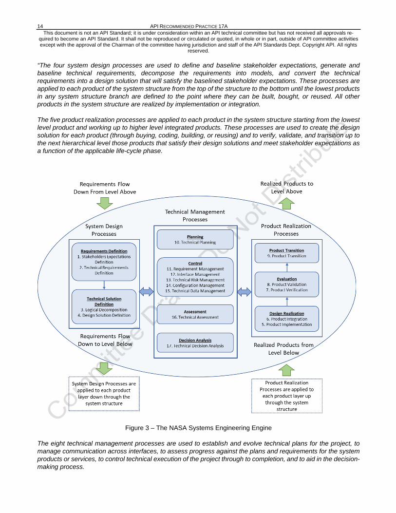
The NASA Systems Engineering Handbook describes three sets of common technical processes (as shown in Figure 3) within the NASA Systems Engineering Engine:
- System Design Processes,
- Technical Management Processes, and
- Project Realization Processes.
As described within the NASA Systems Engineering Handbook:
14 API RECOMMENDED PRACTICE 17A This document is not an API Standard; it is under consideration within an API technical committee but has not received all approvals re-
quired to become an API Standard. It shall not be reproduced or circulated or quoted, in whole or in part, outside of API committee activities except with the approval of the Chairman of the committee having jurisdiction and staff of the API Standards Dept. Copyright API. All rights
reserved. “The four system design processes are used to define and baseline stakeholder expectations, generate and baseline technical requirements, decompose the requirements into models, and convert the technical requirements into a design solution that will satisfy the baselined stakeholder expectations. These processes are applied to each product of the system structure from the top of the structure to the bottom until the lowest products in any system structure branch are defined to the point where they can be built, bought, or reused. All other products in the system structure are realized by implementation or integration.
The five product realization processes are applied to each product in the system structure starting from the lowest level product and working up to higher level integrated products. These processes are used to create the design solution for each product (through buying, coding, building, or reusing) and to verify, validate, and transition up to the next hierarchical level those products that satisfy their design solutions and meet stakeholder expectations as a function of the applicable life-cycle phase.
Figure 3 – The NASA Systems Engineering Engine
The eight technical management processes are used to establish and evolve technical plans for the project, to manage communication across interfaces, to assess progress against the plans and requirements for the system products or services, to control technical execution of the project through to completion, and to aid in the decision-making process.

DESIGN AND OPERATION OF SUBSEA PRODUCTION SYSTEMS―GENERAL REQUIREMENTS AND RECOMMENDATIONS 15 This document is not an API Standard; it is under consideration within an API technical committee but has not received all approvals re-
quired to become an API Standard. It shall not be reproduced or circulated or quoted, in whole or in part, outside of API committee activities except with the approval of the Chairman of the committee having jurisdiction and staff of the API Standards Dept. Copyright API. All rights
reserved.
The processes within the Systems Engineering Engine are used both iteratively and recursively, where “iterative” is the “application of a process to the same product or set of products to correct a discovered discrepancy or other variation from requirements,” and “recursive” is defined as adding value to the system “by the repeated application of processes to design next lower layer system products or to realize next upper layer end products within the system structure. This also applies to repeating application of the same processes to the system structure in the next life cycle phase to mature the system definition and satisfy phase success criteria.” The technical processes are applied recursively and iteratively to break down the initializing concepts of the system to a level of detail concrete enough that the technical team can implement a product from the information. Then the processes are applied recursively and iteratively to integrate the smallest product into greater and larger systems until the whole of the system or product has been assembled, verified, validated, and transitioned.”
NOTE - Comprehensive additional guidance regarding each of these processes is provided in the NASA Systems Engineering Handbook – which is available in the public domain at www.nasa.gov/seh.
5.3 Subsea System Production Assurance and Reliability Management
Production assurance and reliability management is important for the safe and efficient operation of Subsea Production Systems.
Redundancy of equipment, components, and/or functions should be analyzed as a system and should consider safety, cost, reliability, and availability. API 17N can be used as guidance during each of the life cycle phases. Competing options/alternatives can be compared using a life cycle costing approach, as described in ISO 15663. Application of ISO 14224 is relevant to ensure that correct reliability data is used in the reliability work processes. The best available subsea reliability data should be used in these reliability activities and analyses from appropriate sources [e.g. in-house reliability data, Offshore and Onshore Reliability Data (OREDA), JIP Databases and Handbooks]. In-house reliability data should be documented and justified by in-service records, calculations, and/or empirical tests and should be checked for relevance to the proposed service and environmental conditions.
FMECA analysis typically provides input to RAM analysis to eliminate, or mitigate the effects of critical failure modes. RAM analysis can be used to determine:
• the expected system uptime/availability
• probability of success for achieving the reliability performance targets
• sparing consumption and redundancy over field life
• to maintain project availability requirements consistent with maintenance/reliability goals
• identifying critical components whose failure rates have the greatest influence on the overall failure of the system and/or subsystem
Consideration should be given to comparing spare parts lists against existing spare parts inventories managed by operations, particularly for brownfield projects, to optimize required spare parts. A recommended spare parts list and ROV/ROT tooling is typically needed at the start of design to allow time for operations to determine spare order quantity and as input to operations and maintenance activity/procedure development.
Obsolescence of equipment is inevitable and may result in a loss of system availability. Guidance on obsolescence management in subsea systems is provided in 7.2.
Reliability, integrity, and technical risk management during design (from concept to detailed design) manufacture, assembly, testing, installation, and commissioning / systems completion should be performed at a procedural level. Implementation of these activities can be performed by the operator’s subsea system project team and/or by the

16 API RECOMMENDED PRACTICE 17A This document is not an API Standard; it is under consideration within an API technical committee but has not received all approvals re-
quired to become an API Standard. It shall not be reproduced or circulated or quoted, in whole or in part, outside of API committee activities except with the approval of the Chairman of the committee having jurisdiction and staff of the API Standards Dept. Copyright API. All rights
reserved. supplier / contractor. Further information and guidance on this topic can be found in API 17N, ISO/TR 12489 and ISO 20815.
6 Equipment Design Requirements
6.1 Design Basis
This RP recommends a system wide approach when designing and implementing subsea systems. This section discusses general design requirements which should be applied to the equipment design and cites references to relevant documents.
A detailed design basis should be developed to document design input to the equipment design. The Basis of Design document provides the project-specific data and references to key documents such as philosophies used during the design process. The Basis of Design should be updated as the design advances through the project phases.
The Basis of Design typically includes the following:
• A description of the subsea system, • Scope of system, • Design Life, • Reservoir data, • Production profiles, • Metocean data, • Performance requirements, • Regulatory requirements, • References to the relevant codes and standards.
Note: The design of all equipment shall be consistent with all relevant statutory and regulatory requirements.
General guidance regarding functional requirements that should be considered during the design phase can be found in Section 4 of API 17P.
6.2 Safety
6.2.1 General
The strategy and performance standards for safety systems should be developed in accordance with API 17V and recognized principles of health, safety, and environment (HSE) management systems. Additional guidance may be found in IEC 61508, IEC 61511, and NOROG-070.
The system and component level design should incorporate safety aspects of the equipment. This is accomplished by implementing requirements such as:
— Permanent or temporary access ladders, footholds, platforms, fall protection tie-off points, built-in mounts handrail stanchions. (These safety devices should be designed as non-snagging points subsea)
— Temporary and removable ladders, platforms, scaffolds, mounts, and/or handrail stanchions should be provided to complement permanent safety devices where manned intervention is required during manufacturing, load-out, and transportation. These temporary safety devices should not damage subsea structure paint integrity upon removal.

DESIGN AND OPERATION OF SUBSEA PRODUCTION SYSTEMS―GENERAL REQUIREMENTS AND RECOMMENDATIONS 17 This document is not an API Standard; it is under consideration within an API technical committee but has not received all approvals re-
quired to become an API Standard. It shall not be reproduced or circulated or quoted, in whole or in part, outside of API committee activities except with the approval of the Chairman of the committee having jurisdiction and staff of the API Standards Dept. Copyright API. All rights
reserved.
— Permanent lifting and/or tie down points to facilitate handling and temporary securement of heavy equipment loads during transportation should be integrated in equipment design where practical. These permanent safety devices should be designed to not be snagging points subsea.
6.2.2 Safety Strategy
A safety strategy should be developed early in the project cycle. The safety strategy should address all project phases, including manufacturing, fabrication, testing, transportation, installation, operation and recovery. The safety strategy should include the following topics:
— managing technical safety;
— maintaining or improving the level of safety of the system;
— reducing the probability that hazards will arise;
— reducing the probability of a hazard escalating into an undesirable event or condition;
— halting or limiting the escalation process or reduce the scope and duration of undesirable events; and
— limiting the impact of accidents.
Management of technical safety in project development and design processes comprises activities to identify and mitigate risks and develop safety strategies and performance requirements for safety systems and barriers.
— the outcome of a systematic identification and evaluation of the hazards and effects that may arise during design, fabrication, transportation, load-out, installation, systems completion, operation, and abandonment
— define the need for, and role of, the risk reducing measures and safety systems;
— outline the design principles for layout, arrangement, and selection of which safety barriers and systems to go into the design, ensuring a consistent and robust design that will be the basis for a safe operation of the system;
— address operational aspects, which then should serve as an input to the development of the operational procedures.
— involve monitoring of performance in service and during testing and maintenance
— performance should be reassessed against original requirements on a regular basis.
6.2.3 Safety by Design
The outcome of a systematic identification and evaluation of the hazards and effects that may arise will define the need for risk-reducing measures and performance standards for the safety systems. General guidance on tools and techniques for hazard identification and risk assessment, control, and mitigation can be found in ISO 17776.
Emphasis should be placed on inherently safer designs to eliminate or reduce hazards at the source. Applying inherently safer design principals early in project development provides the greatest opportunity for risk reduction and should be part of the system engineering process.
18 API RECOMMENDED PRACTICE 17A This document is not an API Standard; it is under consideration within an API technical committee but has not received all approvals re-
quired to become an API Standard. It shall not be reproduced or circulated or quoted, in whole or in part, outside of API committee activities except with the approval of the Chairman of the committee having jurisdiction and staff of the API Standards Dept. Copyright API. All rights
reserved. 6.3 Barrier and Isolation Considerations
6.3.1 Barrier Philosophy
As part of the overall subsea production system design, a comprehensive barrier philosophy should be developed. The barrier philosophy should provide clear and concise guidance on barrier requirements, with the objective of preventing unintentional release of produced/injected fluids that may harm personnel and/or the environment.
The barrier philosophy should be developed before the commencement of detailed design. The barrier philosphy should define what types and how many barriers are required for operation of the facilities. The barrier philosophy should cover all of the various phases of the field life, including the following:
— installation activities, including tie-in of subsequent wells to a live manifold;
— drilling and completion activities, including well testing and clean-up activities;
— hook-up and commissioning activities;
— routine production operations, for both producing/injecting and shut-in modes as well as for service modes such as circulating of flowlines and pigging;
— well intervention activities, involving reentry into a well and or retrieval of a tree;
— maintenance activities, such as replacement of a subsea choke;
— decommissioning activities.
The barrier philosophy should describe the requirements for the pressure-containing and pressure-controlling elements of the system, from the reservoir to the various boarding/export/isolation valves at the receiving/injecting/service facilities on the host facility or the mobile offshore drilling unit (MODU)/intervention vessel, as applicable.
Where a project/field specific barrier philosophy has not been defined (e.g. for pre-existing subsea production facilities), it is advisable to document the barrier requirements for routine operations of the system (i.e. production, shut-ins, interventions, and barrier testing). A specific barrier philosophy should be developed before any intervention, workover, activity to address those elements not covered in the barrier philosophy document.
Given the wide variety of possible field characteristics and equipment configurations and the varying requirements of existing local regulations combined with field operator preferences, it is not possible or desirable to provide specific guidance that could be used as a standard barrier philosophy.
Typically, barrier philosophies are based on the following principles.
— the barrier philosophy for each subsea production system shall be consistent with all applicable local regulations;
— while some aspects of a barrier philosophy may be applicable to many subsea production systems, each specific situation should be evaluated on a case-by-case basis to at least confirm that the barrier philosophy is appropriate and applicable;
— development of a barrier philosophy requires the use of experienced personnel and typically involves the use of risk assessment techniques such as; hazard and operability study (HAZOP), failure modes and
DESIGN AND OPERATION OF SUBSEA PRODUCTION SYSTEMS―GENERAL REQUIREMENTS AND RECOMMENDATIONS 19 This document is not an API Standard; it is under consideration within an API technical committee but has not received all approvals re-
quired to become an API Standard. It shall not be reproduced or circulated or quoted, in whole or in part, outside of API committee activities except with the approval of the Chairman of the committee having jurisdiction and staff of the API Standards Dept. Copyright API. All rights
reserved.
effects analysis (FMEA), quantitative risk assessment (QRA), task analysis, and/or scenario-based risk assessment;
— the barrier philosophy should be clearly communicated to all relevant personnel, including design engineers, equipment suppliers, and field personnel;
— the guidance/requirements contained in the barrier philosophy should be clear and concise, i.e. not open to different interpretations and/or misinterpretation.
The following documents provide relevant information regarding barrier considerations for subsea equipment:
— API 17P;
— API 17V (provides guidance on recommended XT valve configurations);
— API 90;
— API 96;
— IMCA D044;
— IOGP Report 485;
— ISO 16530-1;
— ISO 16530-2;
— NORSOK D-010;
— OGUK, Well Life Cycle Integrity Guidelines;
— OLF 117.
6.3.2 Barrier Requirements Prior to any subsea operations which involve use or removal of an environmental barrier, a risk/safety assess-ment should be performed to ensure risks are identified and mitigated. Permanent isolation requirements against external leakage for pressurized systems should be provided by dou-ble barriers in all external connection points, (including hot stab receptacles which access bores containing fluids that are not suitable for unintended release to the environment). The primary barrier intended for long-term ser-vice should be metal-to-metal sealing type. Individual barrier integrity should be confirmed by leak testing, and the final dual barrier integrity should be verified. For temporary, time-limited operations, it can be acceptable to use only one metal-to-metal sealing isolation valve for isolating pressurized piping towards the environment. The primary barrier valve should be verified to ensure it is holding pressure prior to releasing the outboard barrier. An overall safety assessment should be per-formed for the activity prior to the start of operations. NOTE If the primary barrier valve cannot be verified, depressurization of the pressurized piping to prevent flow to the environment may be an acceptable alternative to verifying the primary barrier valve. The closure element of a valve (gate, ball) should not be permanently exposed to the environment. Where possi-ble, an inhibited volume should be provided on the environmental side of the isolation valve in order to avoid seawater imposed corrosion of and fouling on the valve.

20 API RECOMMENDED PRACTICE 17A This document is not an API Standard; it is under consideration within an API technical committee but has not received all approvals re-
quired to become an API Standard. It shall not be reproduced or circulated or quoted, in whole or in part, outside of API committee activities except with the approval of the Chairman of the committee having jurisdiction and staff of the API Standards Dept. Copyright API. All rights
reserved. The volume between barrier valves should be maintained with stagnant fluid to minimize issues with corrosion and hydrates (i.e. close both valves with fluid trapped in the volume). 6.3.3 Subsea Isolation Philosophy
A subsea isolation philosophy describes the systems and components where actuated valves are available to provide isolation from pressure sources in the subsea system. The philosophy typically addresses the subsea production system, the subsea injection systems, and the export systems. All remotely actuated subsea isola-tion valves below the boarding valve are typically identified in the subsea isolation philosophy. The document does not typically consider manual or ROV actuated valves. The isolation philosophy should be developed for each field development. The subsea isolation philosophy is different from a barrier philosophy in that it does not contain any requirements. It identifies existing functionality which can be used to mitigate leaks or operational issues. The subsea isolation philosophy can be used to assist with safety studies such as HAZID, HAZOP and SIMOPS. The philosophy typically includes following components from the host facility to the subsea wells including:
— Trees
— Risers
— Flowlines
— Pipelines
— Jumpers
— Subsea Structures
— Chemical Injection Systems
A subsea isolation philosophy typically includes the following topics:
— Description of the subsea configuration
— Description of each major system (e.g., production, water injection, gas injection, gas lift, chemical injection, gas export, oil export)
— Identification and location of each actuated valve which can be used for isolation
6.4 Materials
The project design criteria should be considered when selecting materials for subsea design including design life, inspection and maintenance philosophy, safety and environmental profiles, operational reliability, and specific project requirements. A documented material selection philosophy can be useful during the design process.
General guidance pertaining to materials selection and corrosion control for equipment used in the oil and gas industry can be found in ISO 21457, NACE SP0176 and NORSOK M-001. EEMUA 194 contains specific guidance for materials selection and corrosion control for subsea equipment.
API 6A and several of the API 17 series of documents also contain relevant guidance and requirements regarding materials selection for specific equipment.

DESIGN AND OPERATION OF SUBSEA PRODUCTION SYSTEMS―GENERAL REQUIREMENTS AND RECOMMENDATIONS 21 This document is not an API Standard; it is under consideration within an API technical committee but has not received all approvals re-
quired to become an API Standard. It shall not be reproduced or circulated or quoted, in whole or in part, outside of API committee activities except with the approval of the Chairman of the committee having jurisdiction and staff of the API Standards Dept. Copyright API. All rights
reserved.
Specifically, API 17D contains procedures for screening tests for material compatibility, whilst API 17P contains general guidance on materials and welding for subsea structure components. DNVGL-RP-B204 also provides guidance on welding of subsea equipment.
Guidance on materials for use in H2S-containing environments may be found in ISO 15156, while guidance on the use of duplex stainless steels exposed to cathodic protection is contained in DNVGL-RP-F112.
General guidance on forgings is contained in API 20B and API 20C. DNVGL-RP-0034, DNVGL-SE-0241 and DNVGL-RP-B202 contain specific guidance on carbon and low alloy steel forgings for use in subsea applications.
API 20E and API 20F apply to carbon steel and corrosion resistant bolting, respectively.
DNVGL-RP-B401 provides guidance on cathodic protection design, whilst DNVGL-CP-0107 and DNVGL-CP-0106 provide guidance regarding sacrificial anodes and the associated fastening devices, respectively.
Relevant guidance on protective coatings for subsea equipment is contained in API 17D, ISO 8501-1, ISO 8503, ISO 9588, ISO 12944 and NORSOK M-501. ISO 12736 contains guidance on wet thermal insulation coatings for subsea equipment.
DNVGL-ST-B203 provides guidance on additive manufacturing of metallic parts.
6.5 Structural Analysis
6.5.1 General
Structural analysis of subsea equipment should be completed per the guidance provided in API 17P. The structural analysis should verify that all components and the foundation will retain structural integrity during fabrication, lifting, drilling, installation, operation, workover, and abandonment operations.
6.5.2 Wellhead, Tree, and C/WO Riser System Analysis
Loads on a subsea wellhead system may include component dead loads (i.e. mass, weight, gravity), riser loads, flowline pull-in and expansion loads, thermal growth, and direct environmental action. Depending on the tree system, these loads may be applied to the subsea tree.
Riser loads are transferred to the wellhead/tree system during drilling, well completion, and workover. Depending on the type of subsea system, these loads can be either temporary (i.e. marine drilling riser and C/WO riser) or permanent (i.e. production risers or injection risers). These loads should be determined by performing a riser analysis. Fatigue analysis may also be required where variable loading conditions exist [i.e. due to vessel motions and/or wave/vortex induced vibration (VIV)-induced riser loads].
Applicable loads and applicable load combinations and operational criteria for the determination of riser loads, identification of accidental riser loads, identification of any code break inconsistencies, and their implications should be established during system engineering.
Note that riser design codes account for normal, extreme, and accidental loading conditions. The design codes used for subsea trees and wellhead systems are normally based on rated capacity for normal operating conditions and on the working stress format. Riser codes are based on either Working Stress Design (WSD) format or Load and Resistance Factored Design (LRFD) format.
Further guidance can be found in API 17G, DNVGL-ST-F201, DNVGL-RP-E104, and NORSOK U-001.
22 API RECOMMENDED PRACTICE 17A This document is not an API Standard; it is under consideration within an API technical committee but has not received all approvals re-
quired to become an API Standard. It shall not be reproduced or circulated or quoted, in whole or in part, outside of API committee activities except with the approval of the Chairman of the committee having jurisdiction and staff of the API Standards Dept. Copyright API. All rights
reserved. Flowline pull-in loads can induce significant shear and bending moments on the wellhead. Consideration should be given to the effects of thermal growth or contraction in the well tubulars and attached flowlines and to additional loads due to the possible non-verticality of the wellhead.
For template wells, the interface between the well and the template manifold piping is particularly critical and should be analyzed for tolerances related to variation in temperature, pressure, position, and elements of orientation of both well and manifold components. All permutations in parameter values should be considered, including thermal growth of the well and the well’s different global index with respect to the manifold piping, and any expected subsidence of the template supporting structure. This interface is a typical critical design feature of a template design and should be carefully analyzed.
A subsea completion may be subject to direct environmental loads, for example current, wave action, earthquakes, ice, and soil movements. Dropped objects and snag loads from anchors or trawls can also be a concern for certain applications.
6.6 Pumps, Piping and Valves
Subsea Pumps can be used to boost the flowrate of produced fluids from the subsea facilities to the host, Such pumps require greater levels of power than are required for a typical subsea control system. Guidance on subsea pumps and the related power systems can be found in API 17X, as well as DNVGL-RP-F303 and DNVGL-RP-F401.
Piping analysis of subsea equipment should be completed per the guidance provided in API 17P. External loads, reactions, and fluid characteristics from reservoir and environmental data are used as input to piping analysis of the subsea equipment, including erosion per API 14E and fatigue. Flow path piping analysis typically includes the insulation system and excludes corrosion/erosion allowances (including corrosion-resistant alloy (CRA)-clad material) in any design strength calculation.
Further guidance on piping and valve components can be found in API 17D, API 17G, API 17J, API 17P, API 17R, API 17W, API 6DSS, API 6DSSX, and the Energy Institute’s publication entitled Guidance for the avoidance of vibration-induced fatigue failure in subsea systems.
6.7 Dropped Objects and Fishing Gear Loads
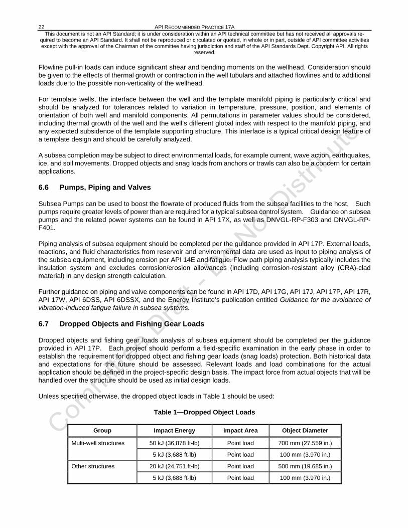
Dropped objects and fishing gear loads analysis of subsea equipment should be completed per the guidance provided in API 17P. Each project should perform a field-specific examination in the early phase in order to establish the requirement for dropped object and fishing gear loads (snag loads) protection. Both historical data and expectations for the future should be assessed. Relevant loads and load combinations for the actual application should be defined in the project-specific design basis. The impact force from actual objects that will be handled over the structure should be used as initial design loads.
Unless specified otherwise, the dropped object loads in Table 1 should be used:
Table 1—Dropped Object Loads
Group Impact Energy Impact Area Object Diameter
Multi-well structures 50 kJ (36,878 ft-lb) Point load 700 mm (27.559 in.)
5 kJ (3,688 ft-lb) Point load 100 mm (3.970 in.)
Other structures 20 kJ (24,751 ft-lb) Point load 500 mm (19.685 in.)
5 kJ (3,688 ft-lb) Point load 100 mm (3.970 in.)

DESIGN AND OPERATION OF SUBSEA PRODUCTION SYSTEMS―GENERAL REQUIREMENTS AND RECOMMENDATIONS 23 This document is not an API Standard; it is under consideration within an API technical committee but has not received all approvals re-
quired to become an API Standard. It shall not be reproduced or circulated or quoted, in whole or in part, outside of API committee activities except with the approval of the Chairman of the committee having jurisdiction and staff of the API Standards Dept. Copyright API. All rights
reserved.
Fishing gear loading (snagging) should be considered as an abnormal operation (plastic limit state condition), while impact and frictional loads caused by passing fishing gear should be regarded as normal operation (ultimate limit state) unless the frequency of trawling allows it to be considered a plastic limit state condition. Unless specified otherwise, the fishing gear loads from fishing gear in Table 2 should be used.
Table 2—Fishing Gear Loads
Design Load Type Design Load Figure (1), (2)
Ground rope friction load 2 × 200 kN (44,961 lbf) 0° to 20° horizontal (2) Ultimate limit state
Trawl board over pull 450 kN (101,163 lbf) (3) 0° to 20° horizontal (2) Accidental limit state
Horizontal impact load 30 kJ (6,743 lbf) Object Diameter 500mm Accidental limit state
Trawl board snag 600 kN (134,885 lbf) 0° to 20° horizontal (4) Accidental limit state (5)
Trawl ground rope snag 1000 kN (224,809 lbf) 0° to 20° horizontal (4) Accidental limit state (5)
Trawl board snag on flowline 600 kN (134,885 lbf) - Accidental limit state (5)
NOTE 1 The loads shall be considered as maximums and the Limit States presented are fixed by load type and are not interchangeable
NOTE 2 The fishing loads described are to be applied, at the extremity of the primary envelope, to protection structures which stand alone and rely on the interface with the seabed for stability. They shall not ap-ply to minor appurtenances to structures and pipelines (such as small protection cages) that are at-tached to the structures and pipelines and do not sit on the seabed & are configured with a snag free profile.
NOTE 3 For closed, smooth protection structures; such as GRP covers, 300kN shall apply NOTE 4 Angles are relative to the horizontal plane NOTE 5 N/A if overtrawlable / snag free
NORSOK U-001 also provides for consideration of model testing to reduce the loads by designing for overtrawlable/snag free structures.
Further guidance on designing for dropped object loads and fishing gear loads can be found in API 17P.
6.8 Lifting Components, Padeyes and Unpressurized Structural Components
The structural components and padeyes should be designed to withstand transportation, lifting, deployment, op-erational and retrieval loads. Such components should be designed in accordance with a recognized and rele-vant industry standard such as API Standard 2CCU, API RP 2A, DNVGL-RP-N201, DNVGL-ST-E273, DNVGL-ST-N001 and / or EEMUA 101. The design factor and other design limitations should be documented in accord-ance with the design standard provisions. Lifting components, such as shackles and sling sets, should be se-lected in accordance with the same design standards. Guidance on the design and testing of padeyes for subsea wellhead and tree equipment is provided in API 17D. 6.9 Colors and Marking
Subsea marking should follow the principles and guidelines provided in API 17H. Load capacity should be marked on all pad eyes and other lifting devices.
A commonality of marking abbreviations among subsea facilities and surface-operating equipment is essential. To minimize confusion and enhance safety where the control units are designed for multiple applications, it is recommended that functions be identified both on the subsea packages and on their control units, using common abbreviations listed in API 17H. If the valve arrangements are unique, the documentation should clearly define the abbreviations used in the marking of equipment.

24 API RECOMMENDED PRACTICE 17A This document is not an API Standard; it is under consideration within an API technical committee but has not received all approvals re-
quired to become an API Standard. It shall not be reproduced or circulated or quoted, in whole or in part, outside of API committee activities except with the approval of the Chairman of the committee having jurisdiction and staff of the API Standards Dept. Copyright API. All rights
reserved. The color and marking system should fulfill the following functions:
Top coat colors should follow the recommendations in API 17H.
identify the structure and orientation;
identify the equipment mounted on the structure and intervention interfaces;
identify the position of any given part of the structure relative to the complete structure;
identify the operational status of the equipment, e.g. connector lock/unlock and valve open/close.
The marking system should enable positive verification of the end stop and/or locked position for retrievable components, such as guideposts to lockdown clamps.
6.10 Tolerance Evaluation
Tolerance evaluation should determine maximum allowable tolerances between mating components and subassemblies (e.g. stack-up, alignment, and engagement) and demonstrate that repeatable interfaces are attainable. Ultimately, this may involve some degree of interchangeability testing as described in Annex A herein.
6.11 Design for Installation
Equipment design should not unnecessarily restrict the installation sequence of the subsea equipment, flowlines, pipelines, risers, and umbilicals. Installed equipment size, shape, configuration, and weight may be limited by handling and installation considerations, both onshore and offshore.
The design of the subsea production system should address the following installation related issues, by ensuring that the relevant components:
— do not rely on hydraulic pressure to retain the necessary locking force in connectors;
— allow for cessation of installation operations without compromising safety;
— BFGsystem functionality);
— are tolerant of small amounts of seabed debris between the interface connections or allow flushing prior to the makeup action;
— are tolerant of hydrodynamic loads including wave-induced, current and hoisting loads;
— avoid loss of harmful fluids into the environment during installation operations.
Constructability analyses should also be completed, in order to ensure that the proposed facilities are constructable in a safe and efficient manner. Such analysis should consider issues such as types of construction equipment required vs that available, pipeline lay direction and potential interference with other seabed equipment, trade-off studies of structure types [e.g. pipeline end manifolds (PLEMs), manifolds, in-line structures], and installation logistics.
6.12 Environmental Considerations
The equipment should be capable of withstanding the environmental conditions to which the equipment may reasonably be expected to be exposed, during fabrication, testing, transportation, storage, installation, and operation, without significant damage or degradation.
DESIGN AND OPERATION OF SUBSEA PRODUCTION SYSTEMS―GENERAL REQUIREMENTS AND RECOMMENDATIONS 25 This document is not an API Standard; it is under consideration within an API technical committee but has not received all approvals re-
quired to become an API Standard. It shall not be reproduced or circulated or quoted, in whole or in part, outside of API committee activities except with the approval of the Chairman of the committee having jurisdiction and staff of the API Standards Dept. Copyright API. All rights
reserved.
The OGUK publication “Seabed environment survey guidelines” provide guidance on seabed survey techniques.
Geohazards (as described in IOGP Report 425) may present a specific risk (i.e., to the integrity of the subsea facilities and/or wells) that needs to be considered in the design of the facilities/wells.
Consideration should be given to the potential impact of the equipment on the existing flora and fauna, including the impact of intended fluid discharges and any noise emanating from the production facilities. IOGP Report 406 provides information regarding the transmission of sound underwater.
6.13 Evaluation of Subsea Pressure Testing Limitations
When defining pressure testing requirements, each subsea hardware subassembly/component's maximum design pressure should be evaluatedto identify potential overpressure points. The evaluation should consider the performance and integrity of each subassembly/component within the system, barrier philosophy, and environmental considerations, in accordance with the subsea system testing philosophy. The following test activities should be evaluated to determine the testing criteria:
— back seal test(s) (initial verification of connection integrity between subassemblies),
— barrier test(s) (often brownfield specific to prove a subassembly/component (e.g. valve, seals) is leak-tight in advance of an internal leak test),
— internal leak test(s) (final verification of connection integrity between subassemblies),
— subsea hydrotest(s) (verification of flowline/pipeline integrity or any other subsea equipment subassembly, which has not already been verified via an onshore hydrotest).
Additional guidance can be found in API 17TR4, API 17TR11, API 17TR12, API 1110, and API 1111.
6.14 Design for Intervention
Subsea equipment design should be influenced by maintenance requirements.
— Equipment components requiring periodic inspection and/or maintenance should be designed to be independently retrievable.
— Components subject to wear under normal operating conditions that require maintenance and/or intervention should be designed and configured in a location that accommodates repair or replacement within the parent equipment or assembly (see API 17H for guidance).
— Method for retrieval of independently retrievable components should be by ROV, with divers as an exception for shallower water depths.
— A method of parking flying leads should be provided in the vicinity of all independently retrievable components.
— All equipment and components of a like design should be designed and fabricated such that they are interchangeable
— ROV/ROT tooling and interfaces should comply with API 17H
— Consideration should be given to the likelihood and severity of marine fouling (including calcareous deposits forming), which may make operation and/or retrieval/installation of some components problematic.
26 API RECOMMENDED PRACTICE 17A This document is not an API Standard; it is under consideration within an API technical committee but has not received all approvals re-
quired to become an API Standard. It shall not be reproduced or circulated or quoted, in whole or in part, outside of API committee activities except with the approval of the Chairman of the committee having jurisdiction and staff of the API Standards Dept. Copyright API. All rights
reserved. The manufacturer should document instructions and requirements concerning maintenance and preservation of equipment.
API 17G defines a minimum set of requirements for performance, design, materials, testing and inspection, hot forming, welding, marking, handling, storing, and shipping of new build subsea well intervention equipment [through-BOP intervention riser system (TBIRS) and open-water intervention riser system (OWIRS)]. Structural design methods and criteria given in API 17G are limited to components manufactured from materials that ensure ductile failure modes (e.g. carbon steels, low-alloy steels, and corrosion-resistant al-loys). Components manufactured from materials that may not ensure ductile failure modes (e.g. composite ma-terials, titanium, and titanium alloys) are beyond the scope of API 17G.
API 17H contains guidance relevant to the development of intervention philosophies and strategies, which should be taken into account in the design of the subsea equipment.
7 Technology Management Guidance 7.1 Technology Development and Qualification
Equipment, methodologies, and modes of operation classified as new or modified technology (or existing technology to be used in a new application) should be suitably qualified prior to use.
Qualification of technology is defined in API 17N, wherein it states that “qualification is the process by which systems are examined and evidence is provided to demonstrate that the technology meets the specified requirements for the intended use.”
In API 17N a distinction is made between standard qualification programs (SQPs) and new technology qualification involving a unique technology qualification program (TQP). The latter will usually require a greater degree of testing and analysis effort to demonstrate that the equipment will meet specified reliability and integrity requirements. The decision to implement a new TQP or SQP depends on the degree of novelty or change in-volved in the design, manufacture or operation of products. Further details regarding TQP and SQP can be found in API 17Q.
Qualification of equipment may also include non-fixed equipment, such as ROV Tooling, WOC Riser Systems and IWOCS.
API 17N, 17Q and DNVGL-RP-A203 all provide further guidance on this topic.
Terminology relevant to technology development and qualification is defined in Annex A (in order to help promote consistent usage of the nomenclature associated with the various stages of product development), including:
- prototype;
- pilot;
- first article;
- product;
- production model / production product.
7.2 Obsolescence Management
Obsolescence of equipment is inevitable and depending on the design basis, it may not be possible to avoid some replacement components becoming unavailable during the field life of the subsea system. Electronic equipment and software are particularly prone to obsolescence.

DESIGN AND OPERATION OF SUBSEA PRODUCTION SYSTEMS―GENERAL REQUIREMENTS AND RECOMMENDATIONS 27 This document is not an API Standard; it is under consideration within an API technical committee but has not received all approvals re-
quired to become an API Standard. It shall not be reproduced or circulated or quoted, in whole or in part, outside of API committee activities except with the approval of the Chairman of the committee having jurisdiction and staff of the API Standards Dept. Copyright API. All rights
reserved.
The negative impacts of obsolescence can be mitigated and/or deferred through a proactive approach, ( e.g. a robust sparing strategy). As obsolescence management is a continuous activity during field life, a comprehensive obsolescence management strategy and plan should be developed during the project development phase, that covers operation of the equipment through to decommissioning.
The obsolescence management strategy and plan should cover the following areas:
a) design of new products;
b) new technology insertion into existing products;
c) support and maintenance of legacy products.
IEC 62402 [49] provides generic guidance for establishing a framework for obsolescence management and for planning a cost-effective obsolescence management process that is applicable through all phases of the product life cycle, wherein the term “product” includes:
— capital equipment;
— infrastructure;
— consumer durables;
— consumables;
— software products.
As described in OTC 25872-MS, two Joint Operator Specification documents (3428A and 3428B) have been created by a joint industry effort, in order to assist the application of IEC 62402 to subsea equipment.
Additional specific guidance on managing obsolescence in subsea systems is also available in API 17F, IOGP Report 551, and the Energy Institute’s publications entitled Guidelines for the management of obsolescence in subsea facilities, and Guidance on managing obsolescence and upgrading industrial automation and control systems (ICAS).
8 Manufacture, Assembly, Testing, Installation and Commissioning Guidance 8.1 Manufacture
API 17D contains recommended guidelines for inquiry and purchase of various subsea equipment, including guidance on Product Specification Levels, Material Class and suggested data the manufacturer will require (in the form of Data Sheets).
Equipment should be manufactured according to the manufacturer’s quality program, relevant industry standards and API Q1.
API Q1 establishes the API quality system requirements necessary for organizations to consistently manufacture products in accordance with API or other specifications. API Q1 sets requirements for all organizations operating under the API Monogram Program. API Q1 applies to those activities that otherwise may be considered a service (i.e.,heat treatment, threading, or testing) if these activities or their results are identified as (or with) an API monogrammable product. Organizations that supply services should meet the requirements of API Q2.
Guidance on the documentation typically required to be provided by the equipment manufacturer can be found in TIRC Z-018 and DNVGL-RP-O101.

28 API RECOMMENDED PRACTICE 17A This document is not an API Standard; it is under consideration within an API technical committee but has not received all approvals re-
quired to become an API Standard. It shall not be reproduced or circulated or quoted, in whole or in part, outside of API committee activities except with the approval of the Chairman of the committee having jurisdiction and staff of the API Standards Dept. Copyright API. All rights
reserved. IOGP S-561 (and the associated documents, being S-561D, S-561L and S-561Q) provides a list of potential supplementary requirements to API 17D, for subsea trees and tubing hangers.
8.2 Assembly
All components, including spares, should be tested for ease of assembly, handling, and interchangeability. Interface checks should be made under static and dynamic conditions.
Jigs and dummies may be used where testing of actual interface components is not practical. It is, however, recommended that the actual equipment be used where feasible. For large orders with identical equipment items, testing should be carried out on the initially produced equipment as a minimum.
Fit tests should be performed in such a way as to prove the guidance and orientation features of the system. In certain cases it is necessary to perform wet-simulation testing in order to prove correct functioning of components and systems underwater.
Certain areas can require cycle testing and make-break testing to prove repeatability of function for new or unqualified designs. Prime targets for this type of testing are valve functions, data transfer functions, hydraulic and chemical connector interfaces, and tooling functions.
Misalignment checks should consider stack-up tolerance, stack-up elevation, horizontal plane orientation and angular alignment. Equipment with self-alignment features should intentionally be misaligned to verify its alignment capability.
Functional checks should include makeup, normal emergency release, reversibility, repeatability, and pressure integrity. The sequence and items to be tested are normally individual components, running tools, subsystems, and the total system assembly.
8.3 Testing
8.3.1 General
Onshore and preinstallation testing can detect early failures in an accessible environment, allowing efficient recording and rectification. Testing should not be a series of isolated test activities but rather a series of related tests that are progressively executed as part of a clearly defined overall project testing strategy and test plan that ensures subsea equipment reliability. The test plan should cover all onshore and preinstallation testing requirements on each subsystem, including the:
— sequence and definition of tests,
— testing requirements for all phases of field life,
— relevant regional and company specific test requirements,
— hardware and software interfaces.
Various tests are typically undertaken on subsea equipment in order to demonstrate that the numerous components, assemblies, and systems have been manufactured in accordance with the specified requirements and are suitable for the intended use.
Performance tests may be appropriate and can supply data on response-time measurements, operating pressures, fluid volumes, and fault-finding and operation of shutdown systems. Cycle testing and make-break testing should

DESIGN AND OPERATION OF SUBSEA PRODUCTION SYSTEMS―GENERAL REQUIREMENTS AND RECOMMENDATIONS 29 This document is not an API Standard; it is under consideration within an API technical committee but has not received all approvals re-
quired to become an API Standard. It shall not be reproduced or circulated or quoted, in whole or in part, outside of API committee activities except with the approval of the Chairman of the committee having jurisdiction and staff of the API Standards Dept. Copyright API. All rights
reserved.
be implemented to prove repeatability and operational life on unqualified designs. Reliability growth testing and accelerated life testing should be performed to validate reliability performance targets.
The following terminology is defined in Annex A (together with examples) to promote uniform usage of the various testing terms commonly used throughout the API 17 series of documents:
— extended factory acceptance test (EFAT);
— factory acceptance test (FAT), including single unit testing;
— interchangeability test (ICT)—typically performed as part of EFAT or SFT;
— pre-deployment test (PDT).
— site received test (SRT);
— system function test (SFT), including factory integration testing;
— system integration test (SIT), including modular-SIT.
NOTE Tests may also include simulations of actual field and environmental conditions for some or all phases or modes of operations, from installation through maintenance. Special tests may be needed for handling and transport, dynamic loading, and backup systems.
8.3.2 Insepction and Test Plans
An Inspection & Test Plan (ITP) is a document which describes the plan for managing the quality control and assurance of a particular element of the construction works providing information on the requirements, overview of the method(s) to be used, responsibilities of relevant parties, and documentary evidence to be provided to verify compliance. The purpose of an Inspection and Test Plan is to document all inspection and testing requirements relevant to a specific process. An Inspection and Test Plan typically identifies:
• Items, materials and work to be inspected or tested • Who is responsible for each of the inspection and testing activities • Stages and/or frequency of the testing • Inspection, Witness and Hold Points in the process • References to relevant standards • Acceptance criteria • Inspection and test records to be maintained
ITPs, when properly implemented, help ensure that, and verify whether, work has been undertaken to the re-quired standard and requirements, and that documented records are created. An ITP should be developed for each major piece of equipment which is consistent with the overall project testing strategy which includes the requirements and acceptance criteria for testing. 8.4 Transportation, Preservation, and Storage
Plans for the transport, preservation, and storage of equipment should address the following issues:
— transportation,

30 API RECOMMENDED PRACTICE 17A This document is not an API Standard; it is under consideration within an API technical committee but has not received all approvals re-
quired to become an API Standard. It shall not be reproduced or circulated or quoted, in whole or in part, outside of API committee activities except with the approval of the Chairman of the committee having jurisdiction and staff of the API Standards Dept. Copyright API. All rights
reserved. — handling,
— security,
— preservation,
— Inspection,
— testing,
— maintenance,
— repair,
— refurbishment.
General transportation requirements (such as tie-down analysis for all delivery modes, protective covers, packaging and handling, etc.) should be addressed and documented. DNVGL-ST-N001 provides guidance on sea transport operations.
Equipment handling plans should address certification of lifting equipment and should take into account that different lifting equipment may be required offshore vs onshore, due to increased dynamic loading factors.
Equipment preservation should take into account the need for protection from environmental conditions:
— equipment should be stored under cover if possible;
— elastomeric/thermoplastic components (and assemblies containing such components, e.g. valve actuators) should not be exposed to direct sunlight for prolonged periods;
— electronic components should be stored in an environmentally (i.e. temperature, humidity, and debris) controlled area;
— hydraulic fluid cleanliness should be maintained;
— appropriate preservation fluids should be used to protect equipment surfaces from long-term degradation.
— inspection and testing may include, but not be limited to, visual inspections, flow tests, function tests, pressure tests, electrical checks, dimensional checks, fluid cleanliness checks, and/or pressure tests.
Routine equipment maintenance may include refreshing equipment preservation and/or hydraulic fluids.
Prior to load-out, equipment that has been stored should be appropriately inspected and/or tested (per A.2.7), and prepared for transport/deployment. In some cases this may involve:
— various de-preservation activities, such as change-out of preservation fluid in the SCM with the control fluid that will be used when the equipment is in operation,
— repair or refurbishment of equipment.
General guidance regarding transportation, preservation and storage of subsea equipment can be found in Section 8 of API 17P.
DESIGN AND OPERATION OF SUBSEA PRODUCTION SYSTEMS―GENERAL REQUIREMENTS AND RECOMMENDATIONS 31 This document is not an API Standard; it is under consideration within an API technical committee but has not received all approvals re-
quired to become an API Standard. It shall not be reproduced or circulated or quoted, in whole or in part, outside of API committee activities except with the approval of the Chairman of the committee having jurisdiction and staff of the API Standards Dept. Copyright API. All rights
reserved.
8.5 Load-out and Installation
Load-out planning is critical to ensure risks are managed between parties and mitigations are put in place. Load-out planning should address, but not be limited to, the following:
— safety, personnel communication, and access,
— sensitive equipment protection during load-out [e.g. flying leads, subsea control modules (SCMs), MPFMs],
— installation aids/sea fastening,
— lifting procedures/crane specifications,
— drawings (e.g. vessel layouts, transportation routes, and vessel/crane elevations),
— quay schedule, load-out sequences/checklists, and constraints relative to transportation vessel, quay, and site,
— mobilization of temporary equipment (e.g. cranes, transports),
— temporary personnel (e.g. marine warranty surveyors),
— marine requirements (e.g. ballasting, bumpers/fenders, moorings, gangways, and additional barges to position vessel),
— potential physical hazards (e.g. sharp edges on support equipment that could damage umbilical, stray electrical currents from welding that could damage electrical equipment).
The methods and equipment used for installation of the subsea equipment should ensure safe and reliable performance of installation operations.
DNVGL-RP-N103 provides guidance for modelling and analysis of marine operations, in particular for lifting operations including lifting through the wave zone and lowering of objects in deep water to landing on the seabed.
Additional references are DNVGL-ST-N001 for load transfer operations, sea transport operations, and lifting operations, DNVGL-RP-N201 and ISO 13535 for guidance on lifting appliances, and DNVGL-RP-N101 for guidance on risk management in marine operations.
Service supply organizations’ quality management systems should meet the requirements of API Q2.
8.6 Commissioning / Systems Completion
Although the vernacular term “commissioning” is still widely used throughout the industry, this phase of the project activities is increasingly referred to by the more comprehensive term “systems completion” of which commissioning is a subpart, as explained below.
As described in API 1FSC systems completion includes:
— factory acceptance testing (insofar as the systems completion process is reliant on the completion of the various tests performed prior to equipment deployment, which in the case of subsea equipment typically involves more than just FAT per se, as described in 8.3);

32 API RECOMMENDED PRACTICE 17A This document is not an API Standard; it is under consideration within an API technical committee but has not received all approvals re-
quired to become an API Standard. It shall not be reproduced or circulated or quoted, in whole or in part, outside of API committee activities except with the approval of the Chairman of the committee having jurisdiction and staff of the API Standards Dept. Copyright API. All rights
reserved. — verification of mechanical completion (which is the point where field construction/installation is complete and
mechanical integrity has been verified);
— precommissioning (which involves activities to verify that the equipment is in the required state of readiness for full dynamic testing), sometimes also referred to as “static commissioning”;
— commissioning (which involves activities undertaken to verify dynamically that the system is ready for start-up), sometimes also referred to as “dynamic commissioning”;
— start-up [which involves the introduction of process fluids (normally hydrocarbons) into the system];
— performance testing (which involves operating the facilities to perform tests vs the design/contract parameters).
Following successful completion of the performance testing, responsibility for the facility is typically transferred from the project team to the operations group.
9 Operations Guidance
9.1 Integrity Management
9.1.1 Condition Monitoring
The ongoing condition of the subsea equipment should be monitored via a combination of assessment of the data available via the subsea control system, performance of periodic underwater inspections, corrosion control, condition monitoring (hydraulic and electrical), and routine integrity testing of critical equipment such as tree valves.
API 14H provides guidance on in situ testing of underwater safety valves (USVs) on subsea trees.
Specific guidance on integrity management data collection is contained in API 17N.
An initial integrity management status inspection should be performed within the early life of a subsea facility to define the initial condition of the facility and compared against known and potential hazards. Engineered barriers of subsea system should be demonstrated to be fit for service. Subsea emergency response procedures should include procedures and techniques for implementation of repair and restoration of an operable subsea system. Subsea systems integrity performance should be reviewed periodically. Monitoring and inspecting subsea system activities should be prioritized based on outcomes of risk assessments and be reassessed based on the results of data analysis.
API 17N provides an understanding of how to manage an appropriate level of reliability and integrity throughout the life cycle of subsea systems and to recognize the trade-offs between up front reliability, integrity, and engineering vs operational integrity management and maintenance.
The Energy Institute’s publications entitled Guidelines for the management of integrity of subsea facilities, Good operational practice on the management of subsea production control systems and associated hydraulic fluids, Guidance on integrity management for subsea production control systems, DNVGL-RP-0002, and EEMUA 227 all provide useful specific guidance regarding the integrity management of various aspects of subsea systems.
DNVGL-RP-F302 provides a summary of industry experiences and knowledge regarding subsea leak detection systems, which can be used as a technical reference.
API 17N, NORSOK U-009 and OLF 122, provide useful guidance regarding the issues and considerations surrounding the use of subsea systems beyond their originally specified service life.

DESIGN AND OPERATION OF SUBSEA PRODUCTION SYSTEMS―GENERAL REQUIREMENTS AND RECOMMENDATIONS 33 This document is not an API Standard; it is under consideration within an API technical committee but has not received all approvals re-
quired to become an API Standard. It shall not be reproduced or circulated or quoted, in whole or in part, outside of API committee activities except with the approval of the Chairman of the committee having jurisdiction and staff of the API Standards Dept. Copyright API. All rights
reserved.
API 18LCM defines the requirements of a management system for service providers performing life cycle man-agement of pressure containing and/or pressure-controlling products for wellbore fluids, and may also be applied to other equipment that is specified by the product owner or customer. DNVGL-RP-O501 provides guidance on managing sand production and erosion. The OGUK publications entitled Flexible pipe integrity management guidance and good practice, Guidance note on monitoring methods and integrity assurance for unbonded flexible pipes, Guideline on ageing and life exten-sion of subsea pipelines and risers, and State of the art report on flexible pipe integrity, provide guidance relating to the integrity management of flexible pipes. 9.1.2 Reliability Data Collection/Reporting
A failure reporting process should be in place, and all equipment failures should be communicated back to the original equipment manufacturer (OEM), so that lessons learned can be appropriately incorporated into future designs. ISO 14224 provides guidance on the collection and exchange of reliability and maintenance data.
9.1.3 Subsea Production System Maintenance
Various maintenance tasks can be performed on equipment located on or near the seabed (i.e. choke inserts, control modules, valves, flowmeters, manifolds, templates, etc.) by modular replacement or via in situ repairs by ROV/divers. IMCA D044 provides guidance regarding isolation and intervention during diver access to subsea systems. IOGP Report 570 lists various hazards that should be considered prior to commencing intervention work on subsea facilties.
Surface equipment (i.e. production control system components, chemical injection systems, etc.) should be maintained via implementation of a routine maintenance program.
9.2 Production Management
Routine operation of the subsea system requires careful control of all of the relevant operating parameters. Subsea production systems (vs subsea water/gas injection systems) involve multiphase flow and therefore should be carefully managed with respect to a number of related issues, including start-up, shutdown, and solids management.
Most subsea production systems rely on some level of chemical injection as part of the solids management strategy; therefore, particular care should be taken with the management of the chemical injection system, especially with respect to blocking lines/injection points as described in API TR5 and API TR6.
Production optimization and long-term reservoir management are also typically more challenging for subsea production systems than for production systems using dry trees, e.g. well testing of subsea wells.
10 Well Intervention Guidance
Where a well is accessed vertically, appropriate subsea or surface BOP equipment should be employed that satisfies the required service conditions and conforms with accepted industry practices and applicable regulations.
Subsea wells should be safely secured prior to commencing any well intervention involving potential exposure to live well fluids. Refer to 6.3 for guidance on barrier considerations.
Extreme care should be taken when lowering and landing tools that connect to the subsea tree and/or wellhead, to minimize potential damage to installed components. If possible, the rig or surface vessel should be displaced

34 API RECOMMENDED PRACTICE 17A This document is not an API Standard; it is under consideration within an API technical committee but has not received all approvals re-
quired to become an API Standard. It shall not be reproduced or circulated or quoted, in whole or in part, outside of API committee activities except with the approval of the Chairman of the committee having jurisdiction and staff of the API Standards Dept. Copyright API. All rights
reserved. to a position offset from the center of the well when handling and running packages, in order to reduce the risk of dropping objects or debris onto the well or adjacent components.
After completion of the well intervention, downhole and tree components should be reinstalled and tested in accordance with the relevant installation procedures.
The well control during a well intervention should only be possible via the workover control system. It should be possible to initiate a shutdown of associated neighboring wells from the well intervention vessel by reliable communication with the host facility.
All subsea tree valves that can prevent downhole access in the event of hydraulic failure should be equipped with a mechanical override feature.
IOGP Reports 594 and 595 provide guidance on emergency response planning, and capping stacks, for subsea wells.
11 Decommissioning Guidance
The variable elements related to decommissioning are the plugging and abandonment of wells, any necessary removal of seabed equipment, seabed clean-up, and final survey. The effect on the operating environment, e.g. discharge of hydrocarbons during decommissioning, should be minimized.
The subsea production system should, at decommissioning:
— allow cessation of operations without compromising safety;
— allow production products and chemicals to be flushed from subsea trees, umbilicals, flowlines, pressure vessels, manifolds, etc.;
— allow any hydrocarbon-containing equipment to be removed or, if left in place, be flushed clean. The flushed fluid should be recovered at the surface to avoid unintended releases to the environment.
When the decision has been made to abandon subsea equipment, the method of abandonment should be reviewed in light of changes to the applicable equipment and removal technology. In certain situations, it may be acceptable the equipment may be left in place. If it is to be removed, it is recommended that a subsea survey be conducted to ascertain the physical condition. The integrity of the lifting points and ballasting system, if fitted, is critical. After collecting the desired information, a detailed plan of removal should be developed.
API 17N, the Energy Institute’s publication entitled Guidance on managing human and organizational factors in decommissioning, and the OLF publication entitled Decommissioning work breakdown structure handbook, contain general guidance relevant to decommissioning of subsea equipment.
IOGP Reports 469 and 584, plus the OGUK publications entitled Decommissioning of pipelines in the North Sea region, Guidelines on late-life/decommissioning inspection and maintenance, Long term degradation of offshore structures and pipelines: decommissioned and left in-situ, and The management of marine growth during decommissioning, also provide guidance on decommissioning of subsea facilities.
DNVGL-RP-E103, IOGP Report 585 and the OGUK publications entitled Guidelines for the abandonment of wells, and Well decommissioning guidelines, contain guidance on abandonment of subsea wells.
DESIGN AND OPERATION OF SUBSEA PRODUCTION SYSTEMS―GENERAL REQUIREMENTS AND RECOMMENDATIONS 35 This document is not an API Standard; it is under consideration within an API technical committee but has not received all approvals re-
quired to become an API Standard. It shall not be reproduced or circulated or quoted, in whole or in part, outside of API committee activities except with the approval of the Chairman of the committee having jurisdiction and staff of the API Standards Dept. Copyright API. All rights
reserved.
Retrieval of equipment should address the possible presence of naturally occurring radioactive materials (NORM), per API E2.
After the abandonment operation, the site should be surveyed and mapped for remaining equipment/debris.

36 API RECOMMENDED PRACTICE 17A This document is not an API Standard; it is under consideration within an API technical committee but has not received all approvals re-
quired to become an API Standard. It shall not be reproduced or circulated or quoted, in whole or in part, outside of API committee activities except with the approval of the Chairman of the committee having jurisdiction and staff of the API Standards Dept. Copyright API. All rights
reserved.
Annex A (informative)
Generic Terms for Use in API 17-series Documents
A.1 Introduction
The intention of this annex is to promote uniform usage of various terms commonly used throughout the API 17 series of documents, particularly relating to the qualification and testing of products.
A.1.1 The definitions provided herein use the terms “qualification,” “verification,” and “validation” extensively. These terms can have a very broad application, ranging from activities undertaken on new/unique products (including those based on new technologies) being developed and tested for the first time through to the types of activities applied to routine products being tested post-manufacture in order to confirm compliance with various specified requirements.
Notwithstanding the above, the usage of these three terms is based upon the following existing definitions in ISO 9000.
Qualification Process Process to demonstrate the ability to fulfil specified requirements. NOTE 1 The term “qualified” is used to designate the corresponding status. NOTE 2 Qualification can concern persons, products, processes, or systems. EXAMPLE Auditor qualification process, material qualification process.
Verification Confirmation, through the provision of objective evidence, that specified requirements have been fulfilled. NOTE 1 The term “verified” is used to designate the corresponding status. NOTE 2 Confirmation can comprise activities such as
― performing alternative calculations, ― comparing a new design specification with a similar proven design specification, ― undertaking tests and demonstrations, and ― reviewing documents prior to issue.
Validation Confirmation, through the provision of objective evidence, that the requirements for a specific intended use or application have been fulfilled. NOTE 1 The term “validated” is used to designate the corresponding status. NOTE 2 The use conditions for validation can be real or simulated.
A.1.2 The associated terms of “design and development verification” and “design and development validation” are based upon the following definitions in API Q1.
Design and Development Verification Process of examining the result of design and development output to determine conformity with specified requirements. NOTE Design verification activities can include one or more of the following (this is not an all-inclusive list):
DESIGN AND OPERATION OF SUBSEA PRODUCTION SYSTEMS―GENERAL REQUIREMENTS AND RECOMMENDATIONS 37 This document is not an API Standard; it is under consideration within an API technical committee but has not received all approvals re-
quired to become an API Standard. It shall not be reproduced or circulated or quoted, in whole or in part, outside of API committee activities except with the approval of the Chairman of the committee having jurisdiction and staff of the API Standards Dept. Copyright API. All rights
reserved.
a) confirming the accuracy of design results through the performance of alternative calculations, b) review of design output documents resulting from design and development activities, c) comparing new designs to similar proven designs.
Design and Development Validation Process of proving a design by testing to demonstrate conformity of the product to design requirements. NOTE Design validation can include one or more of the following (this is not an all-inclusive list): a) prototype tests, b) functional and/or operational tests of production products, c) tests specified by industry standards and/or regulatory requirements, d) field performance tests and reviews.
A.2 Terms for Use in API 17-series Documents (in Alphabetical Order)
A.2.1 Extended Factory Acceptance Test (EFAT)
Definition: Test(s) conducted to verify that the specified requirements, for a set of interfacing products, have been fulfilled.
Typical Activities: Test(s) conducted (typically by the supplier) to verify that the various physical and functional interfaces involved in mating of individual products are in accordance with the specified requirements.
Notes: Typically conducted on individual products that have previously been subjected to FAT. May involve some degree of interchangeability testing (ICT). Differs from FAT, in that the product interfaces tested during EFAT are those that typically can/will actually occur at the installation site.
Examples: Interfacing of:
― tree with tree running tool (TRT);
― tubing hanger with tubing hanger running tool (THRT);
― tree with wellhead;
― tree with tubing hanger and wellhead;
― installation workover control system (IWOCS) with IWOCS umbilical and tree;
― SCM with subsea tree;
― SCM with MCS;
― MCS with hydraulic power unit (HPU);
― flying leads with subsea umbilical distribution unit (SUDU);
― flying leads with subsea trees;
38 API RECOMMENDED PRACTICE 17A This document is not an API Standard; it is under consideration within an API technical committee but has not received all approvals re-
quired to become an API Standard. It shall not be reproduced or circulated or quoted, in whole or in part, outside of API committee activities except with the approval of the Chairman of the committee having jurisdiction and staff of the API Standards Dept. Copyright API. All rights
reserved.
― casing hangers and seal assemblies with wellhead.
A.2.2 Factory Acceptance Test (FAT)
Definition: Test(s) conducted to verify that the specified requirements, for a product, have been fulfilled.
Typical Activities: Test(s) conducted (typically by the supplier) to verify that the manufacture of a specific product is in accordance with the specified requirements.
Notes: Typically conducted on each individual functional product. Differs from EFAT, in that products tested during FAT are typically installed “as is” at the installation site, i.e. without being disassembled after FAT, and therefore not requiring reassembly/interfacing at the installation site.
A series of successive FATs may be completed as higher level assemblies are produced by the combination of various components/sub-assemblies. For example, valves bodies are typically pressure tested, before being fitted with an actuator for functional testing. The completed valve assembly is then fitted into a tree/manifold for overall pressure and function testing. The FAT of such a sub-component and/or sub-assembly is often referred to as a Single Unit Test.
Examples: FAT per API 17D of:
― subsea tree, per supplier’s written specification;
― valves and actuators;
― tree cap;
― tree cap running tool (TCRT);
― TRT;
― flowline connector systems;
― subsea chokes;
― wellhead housing;
― casing hanger;
― hanger seal assembly;
― tubing hanger;
― THRT.
FAT of control system products, per API 17F:
― SCM;
― HPU;

DESIGN AND OPERATION OF SUBSEA PRODUCTION SYSTEMS―GENERAL REQUIREMENTS AND RECOMMENDATIONS 39 This document is not an API Standard; it is under consideration within an API technical committee but has not received all approvals re-
quired to become an API Standard. It shall not be reproduced or circulated or quoted, in whole or in part, outside of API committee activities except with the approval of the Chairman of the committee having jurisdiction and staff of the API Standards Dept. Copyright API. All rights
reserved.
― master control station (MCS);
― hydraulic and electric flying leads (HFLs/EFLs);
― SUDU.
FAT of C/WO riser system and workover control system products, per API 17G.
A.2.3 Field Proven
Definition: Products that are sufficiently similar, to products previously used in a given environment/application, such that there is a very high likelihood of achieving similar performance results, especially in terms of reliability and integrity.
Notes: The definition of what can be considered “field proven” is obviously quite subjective and therefore there needs to be full alignment (between the supplier and the customer) for each individual product (based on evaluation of documented evidence), as to whether it can be considered “field proven” or not, for a specific application.
A.2.4 First Article
Definition: The first of a product produced using the “normal processes” as will be used to make multiple numbers of the same product.
Notes: As distinct from a prototype, a first article should accurately represent all aspects and functionality of the production model product.
The “normal processes” would typically include the standard design, procurement, manufacture, QA/QC and testing processes as would be used in the production of a Production Model / Production Product.
Such a product is suitable for normal use.
First Article products are often subjected to comprehensive verification and validation testing, as well as subsequent strip down and inspection for evidence of component deterioration and/or loss of functionality.
Examples: The first of a new design of SCM manufactured on a production line and intended for use in the field.
A.2.5 Interchangeability Test (ICT)
Definition: Test(s) conducted to verify the interchangeability requirements of "identical" products, which may be interfaced with other mating products at the installation site, have been fulfilled.
Typical Activities: Interchangeability can be physically confirmed by:
― testing of physical and functional interfaces between two or more interchangeable products, or
― testing of physical and functional interfaces between an interchangeable product and a test jig (or fixture).
40 API RECOMMENDED PRACTICE 17A This document is not an API Standard; it is under consideration within an API technical committee but has not received all approvals re-
quired to become an API Standard. It shall not be reproduced or circulated or quoted, in whole or in part, outside of API committee activities except with the approval of the Chairman of the committee having jurisdiction and staff of the API Standards Dept. Copyright API. All rights
reserved. Notes: Typically performed as part of EFAT or SFT.
Examples: Interchangeability testing of mating trees, tubing hangers, caps and running tools, as referred to in API 17D.
Interchangeability testing (both physical and functional) of an SCM with more than one subsea tree or manifold.
A.2.6 Pilot
Definition: The first of a product used for an extended period in the intended service in order to validate a concept or process, prior to the manufacture and deployment of additional similar products.
Notes: Similar to a prototype, a pilot is usually a “one off” and therefore is often not produced using the exact same processes as will be used to make the actual production model of a product (of which multiple numbers are typically produced).
However unlike a prototype, a pilot needs to accurately represent all aspects and functionality of the intended production model product in order to be a valid test and to be suitable for use in the field.
Based on the results gained from the extended field testing of a pilot, it is not uncommon for the actual production model to be somewhat different from the pilot in some aspects.
Examples: The Troll Pilot subsea separation system.
A.2.7 Pre-deployment Test (PDT)
Definition: Test(s) conducted to verify that the specified requirements, for a product that is ready for deployment, are still fulfilled.
Typical Activities: The first part of the PDT will typically involve completion of an appropriate SRT, which will be followed by preparation of the products for deployment.
PDT typically includes, but is not limited to:
― cleaning of the product;
― visual inspection for damage;
― de-preservation activities, if required (per 8.4);
― checking of critical functions.
Following completion of the PDT activities, the product will then be prepared for deployment (e.g. removal of protective covers and test seals, fitting of final seals, pre-charging of accumulators, pre-pressuring of flying leads).
Notes: The extent of the PDT will be dependent on a number of factors, including but not limited to:
― the level of equipment preservation and maintenance performed whilst in storage;
DESIGN AND OPERATION OF SUBSEA PRODUCTION SYSTEMS―GENERAL REQUIREMENTS AND RECOMMENDATIONS 41 This document is not an API Standard; it is under consideration within an API technical committee but has not received all approvals re-
quired to become an API Standard. It shall not be reproduced or circulated or quoted, in whole or in part, outside of API committee activities except with the approval of the Chairman of the committee having jurisdiction and staff of the API Standards Dept. Copyright API. All rights
reserved.
― the time the equipment was in storage and the environment it was exposed to;
― the distance transported;
― the method of transport;
― the duration of the transport;
― exposure to the environment during transport.
Examples: PDT would be performed after delivery of a product from an onshore storage site to an offshore installation site.
In the case of equipment that has been stored for an extended period (and perhaps under less than ideal conditions) PDT may also be deemed to be necessary well in advance of preparing to ship the equipment to an offshore installation site, so as to identify all issues sufficiently ahead of time so as to allow time to address them.
A.2.8 Product
Definition: The term “product” is defined in ISO 9000 as being the “result of a process”, where a process is defined as a “set of interrelated or interacting activities which transforms inputs into outputs”.
Examples: ISO 9000 recognizes 4 generic product categories, being:
- Services (e.g. transport);
- Software (e.g. computer program);
- Hardware (e.g. mechanical parts);
- Processed materials (e.g. lubricant).
A.2.9 Production Model/Production Product
Definition: A product manufactured using the “normal processes” and intended for normal use.
Notes: Often a production model is one of a multiple number of the same product.
The term “production model” is used herein due to its prior use in API 6A.
The “normal processes” should be fully defined and documented (in advance), and would include the design, procurement, manufacture, QA/QC and testing processes used in the production of the product.
Examples: An SCM manufactured on a production line and intended for use in the field.
A.2.10 Prototype
Definition: A trial product produced to test a concept or process.
42 API RECOMMENDED PRACTICE 17A This document is not an API Standard; it is under consideration within an API technical committee but has not received all approvals re-
quired to become an API Standard. It shall not be reproduced or circulated or quoted, in whole or in part, outside of API committee activities except with the approval of the Chairman of the committee having jurisdiction and staff of the API Standards Dept. Copyright API. All rights
reserved. Notes: A prototype is usually a “one off” and therefore is often not produced using the exact same
“normal processes” as will be used to make the actual production model of a product (of which multiple numbers are often produced), e.g. it may be produced in a laboratory environment rather than in a factory environment, using specialist personnel.
A prototype often does not accurately represent all aspects and functionality of the complete production model/product, as it may only be used to test certain specific aspects of the concept or process. Hence, such a product is often not suitable for normal/extended use, and is often disassembled for inspection/testing after prototype testing is complete, in order to identify potential design improvements.
Examples: A prototype gate valve manufactured for the purpose of validating a new design.
A.2.11 Sample
Definition: A small portion taken from a quantity to give an idea of the whole.
Notes: Samples are usually subjected to some type of inspection and/or testing in order to confirm that specified requirements have been fulfilled.
Examples: A number of bolts taken from a larger quantity and tested, prior to use of the bolts in an assembled product.
A.2.12 Site Received Test (SRT)
Definition: Test(s) conducted to verify that the specified requirements, for a product that has been transported from one site to another, are still fulfilled.
Typical Activities: SRT typically includes, but is not limited to:
― cleaning of the product;
― visual inspection for damage;
― replication of relevant portions of the FAT/EFAT.
Notes: The extent of the SRT will be dependent on a number of factors, including but not limited to:
― the distance transported;
― the method of transport;
― the duration of the transport;
― exposure to the environment during transport.
Examples: SRT would be performed after delivery of a product:
― from a subsupplier to a supplier, e.g. “delivery acceptance” testing of umbilical components as per API 17E;
― from one supplier site to another supplier site, e.g. transport of an SCM to a tree manufacturing site, for completion of EFAT or SFT;
― from a supplier site to a third-party testing site, e.g. for SFT or SIT;
DESIGN AND OPERATION OF SUBSEA PRODUCTION SYSTEMS―GENERAL REQUIREMENTS AND RECOMMENDATIONS 43 This document is not an API Standard; it is under consideration within an API technical committee but has not received all approvals re-
quired to become an API Standard. It shall not be reproduced or circulated or quoted, in whole or in part, outside of API committee activities except with the approval of the Chairman of the committee having jurisdiction and staff of the API Standards Dept. Copyright API. All rights
reserved.
― from a supplier to a customer.
A.2.13 System
Definition: The term “system” is defined (by INCOSE) as “an arrangement of parts or elements that together exhibit behavior or meaning that the individual constituents do not.”
Refer to the INCOSE “Systems Engineering Handbook” (and associated papers) for more detail.
A.2.14 System Function Test (SFT)
Definition: Test(s) conducted to validate that the requirements for a specific intended use or application, of a set of products that form a “complete” (1) functional system, have been fulfilled.
(1) The system may not be totally complete using the actual products to be installed in the field, e.g. a test of the production control system would typically use an umbilical simulator, rather than the actual umbilical itself.
Typical Activities: Test(s) conducted [typically by the supplier(s)] to validate that the individual products meet the requirements for a specific intended use, when operating as part of a “complete” functional system.
Notes: Typically involves nondestructive testing performed on an assembly of individual products that have previously been subjected to FAT and EFAT. May also involve some level of interchangeability testing (ICT).
Typically performed onshore, but may include shallow and/or deep water testing if new designs are involved, for which there is insufficient field experience. The requirement for (some or all) testing may be foregone in some cases based on the prior performance of similar “field proven” products, provided there is agreement between the supplier and the customer to do so.
If multiple suppliers are involved, then the test(s) are typically performed under the direction of the customer.
In some cases, sub-systems of a “complete” system may be tested prior to assembly and testing of the “complete” system. This is typically done before the equipment leaves the factory environment and hence is often referred to as a Factory Integration Test.
Examples: Functional test of the production control system for a subsea tree by testing of the interconnected MCS, HPU, umbilical simulator, SUDU, flying leads, SCM, and subsea tree.
A.2.15 System Integration Test (SIT)
Definition: Test(s) conducted to validate that the requirements for a specific intended use or application, of a set of products that form an integrated system, have been fulfilled.
Typical Activities: Test(s) conducted (typically under the direction of the customer) to validate that the various interfaces involved in mating of individual products, particularly from different suppliers, meet the requirements for a specific intended use.
44 API RECOMMENDED PRACTICE 17A This document is not an API Standard; it is under consideration within an API technical committee but has not received all approvals re-
quired to become an API Standard. It shall not be reproduced or circulated or quoted, in whole or in part, outside of API committee activities except with the approval of the Chairman of the committee having jurisdiction and staff of the API Standards Dept. Copyright API. All rights
reserved. Notes: Typically involves nondestructive testing performed on an assembly of individual products
that have been previously subjected to FAT, EFAT, and SFT.
Typically performed onshore, but may include shallow and/or deep water testing if new designs are involved for which there is insufficient field experience.
The requirement for (some or all) testing may be foregone in some cases based on the prior performance of similar “field proven” products, provided there is agreement between the supplier and the customer to do so.
Typically conducted on the actual products to be used, but may also involve use of test jigs and/or mock-ups of some components.
Usually involves a high emphasis on testing of procedures (e.g. covering installation, retrieval, diagnostic, maintenance, and contingency procedures), as well as training of personnel (from both the installation and operation teams).
In some cases, it may be expeditious to conduct various portions of the SIT at separate locations, in which case the term “Modular-SIT” may be applied. Such an approach may be suitable for testing of physical interfaces, but particular care must be taken if applying this approach to the testing of closely integrated functional interfaces which may not necessarily involve a direct physical interface.
Examples: Operation of ROV tooling, including tests for ROV accessibility (using a mock-up or real ROV) and tolerance requirements.
Installation and retrieval of flowline jumpers between subsea trees and the manifold. Deployment and connection of flying leads between the SUDU and subsea trees/manifold.
Specific guidance on tests recommended for subsea structures and manifolds can be found in API RP17P Section 12.
A.2.16 Validation Testing
Definition: Test(s) conducted to confirm that the requirements for a specific intended use (1) or application of a product have been fulfilled.
(1) The “intended use” should include use in all situations that are reasonably foreseeable, including situations involving common failures.
Typical Activities: Test(s) conducted as part of validation type activities during product development, using prototypes, pilots, and/or first articles, under conditions designed to replicate key service parameters.
Test(s) conducted as part of SFT and/or SIT of pilots, first articles, or production models, under conditions designed to replicate key service parameters.
Notes: If performed as part of a product development activity (e.g. on a prototype, pilot or first article), then validation testing often results in significant degradation, or the destruction, of the product being tested.
May include “product family validation” as explained in API 17D.
DESIGN AND OPERATION OF SUBSEA PRODUCTION SYSTEMS―GENERAL REQUIREMENTS AND RECOMMENDATIONS 45 This document is not an API Standard; it is under consideration within an API technical committee but has not received all approvals re-
quired to become an API Standard. It shall not be reproduced or circulated or quoted, in whole or in part, outside of API committee activities except with the approval of the Chairman of the committee having jurisdiction and staff of the API Standards Dept. Copyright API. All rights
reserved.
Typically performed onshore, but may include shallow and/or deep water testing.
A product that undergoes a substantive change (e.g. of design or manufacturing process) becomes a new product requiring revalidation as explained in API 6A.
Multiple validations should be carried out if there are different intended uses of the same product or if the intended use changes after the product has already been validated e.g. a valve previously validated for liquid service (PSL 3) would need to be re-validated for gas service (PSL 3G).
The requirement for (some or all) validation testing may be foregone in some cases based on the prior performance of similar “field proven” products, provided there is agreement between the supplier and the customer to do so.
Examples: Validation testing of subsea wellhead and tree products, per API 17D.
“Product family validation,” per API 17D.
Validation testing of tree cap, per API 17D.
Validation testing of flowline connector systems per API 17D.
Validation testing of USVs per API 6AV1.
A.2.17 Verification Testing
Definition: Test(s) conducted to confirm that the specified requirements for a product have been fulfilled.
Typical Activities: Test(s) conducted as part of verification type activities during product development using prototypes, pilots, and/or first articles.
Test(s) conducted as part of FAT and/or EFAT of pilots, first articles, or production models.
Notes: If performed as part of a product development activity (e.g. on a prototype, pilot or first article), then verification testing may result in significant degradation, or the destruction, of the product being tested.
A product that undergoes a substantive change (e.g. of design or manufacturing process) becomes a new product requiring reverification.
If performed as part of an FAT or EFAT activity of a first article or production model, then verification testing does not usually result in a significant degradation, or the destruction, of the product being tested, except in the case where a sample is being tested, e.g. a subsea umbilical sample from a main production run.
The requirement for (some or all) verification testing may be foregone in some cases based on the prior performance of similar “field proven” products, provided there is agreement between the supplier and the customer to do so.
Examples: Verification testing of a production length of umbilical as per API 17E.

This document is not an API Standard; it is under consideration within an API technical committee but has not received all approv-als required to become an API Standard. It shall not be reproduced or circulated or quoted, in whole or in part, outside of API com-mittee activities except with the approval of the Chairman of the committee having jurisdiction and staff of the API Standards Dept.
Copyright API. All rights reserved.
46
Bibliography
API 17-series Technical Reports [1] API Technical Report 17TR1, Evaluation Standard for Internal Pressure Sheath Polymers for High
Temperature Flexible Pipes
[2] API Technical Report 17TR2, The Ageing of PA-11 in Flexible Pipes
[3] API Technical Report 17TR3, An Evaluation of the Risks and Benefits of Penetrations in Subsea Wellheads Below the BOP Stack
[4] API Technical Report 17TR4, Subsea Equipment Pressure Ratings
[5] API Technical Report 17TR5, Avoidance of Blockages in Subsea Production Control and Chemical Injection Systems
[6] API Technical Report 17TR6, Attributes of Production Chemicals in Subsea Production Systems
[7] API Technical Report 17TR7 Verification and Validation of Subsea Connectors
[8] API Technical Report 17TR8, High-Pressure High-Temperature Design Guidelines
[9] API Technical Report 17TR9, Subsea Umbilical Termination (SUT) Selection and Sizing Recommendations
[10] API Technical Report 17TR10, Subsea Umbilical Termination (SUT) Design Recommendations
[11] API Technical Report 17TR11, Pressure Effects on Subsea Hardware During Flowline Pressure Testing in Deep Water
[12] API Technical Report 17TR12, Consideration of External Pressure in the Design and Pressure Rating of Subsea Equipment
[13] API Technical Report 17TR13, General Overview of Subsea Production Systems
Additional API Documents
[14] API Recommended Practice 1FSC, Facilities Systems Completion Planning and Execution
[15] API Recommended Practice 2A, Planning Designing, and Constrcuting Fixed Offshore Platforms – Working Stress Design
[16] API Standard 2CCU, Lifting Containers
[17] API Specification 6A, Specification for Wellhead and Tree Equipment
[18] API Specification 6AV1, Specification for Validation of Wellhead Surface Safety Valves and Underwater Safety Valves for Offshore Service
[19] API 6DSS, Specification for Subsea Pipeline Valves
[20] API Standard 6DSSX, Operator and Mounting Kits for Subsea Pipeline Valves
[21] API Recommended Practice 14E, Recommended Practice for Design and Installation of Offshore Production Platform Piping Systems
DESIGN AND OPERATION OF SUBSEA PRODUCTION SYSTEMS―GENERAL REQUIREMENTS AND RECOMMENDATIONS 47 This document is not an API Standard; it is under consideration within an API technical committee but has not received all approv-als required to become an API Standard. It shall not be reproduced or circulated or quoted, in whole or in part, outside of API com-mittee activities except with the approval of the Chairman of the committee having jurisdiction and staff of the API Standards Dept.
Copyright API. All rights reserved.
[22] API Recommended Practice 14H, Recommended Practice for Installation, Maintenance and Repair of Surface Safety Valves and Underwater Safety Valves Offshore
[23] API 18LCM, Product Life Cycle Management System Requirements
[24] API Specification 20B, Open Die Shaped Forgings for Use in the Petroleum and Natural Gas Industry
[25] API Standard 20C, Closed Die Forgings for Use in the Petroleum and Natural Gas Industry
[26] API 20E, Alloy and Carbon Steel Bolting
[27] API 20F, Corrosion Resistant Bolting
[28] API RP90, Annular Casing Pressure Management for Offshore Wells
[29] API Recommended Practice 96, Deepwater Well Design and Construction
[30] API Recommended Practice 1110, Recommended Practice for the Pressure Testing of Steel Pipelines for the Transportation of Gas, Petroleum Gas, Hazardous Liquids, Highly Volatile Liquids, or Carbon Dioxide
[31] API Recommended Practice 1111, Design, Construction, Operation, and Maintenance of Offshore Hydrocarbon Pipelines (Limit State Design)
[32] API Bulletin E2, Bulletin on Management of Naturally Occurring Radioactive Materials (NORM) in Oil and Gas Production
Additional (Non-API) Documents
[33] DNVGL-CP-0106 Fastening Devices for Sacrifical Anodes - Metallic Materials
[34] DNVGL-CP-0107 Sacrifical Anode Materials - Metallic Materials
[35] DNVGL-RP-0002 (2019): Integrity management of subsea production systems
[36] DNVGL-RP-0034 (2019): Steel forgings for subsea applications
[37] DNVGL-RP-A203 (2019): Technology qualification
[38] DNVGL-RP-B202 Steel Forgings for Subsea Applications - QM Requirements
[39] DNVGL-RP-B204 Welding of subsea production system equipment
[40] DNVGL-RP-B401 (2017): Cathodic protection design
[41] DNVGL-RP-E103 Risk-based abandonment of wells
[42] DNVGL-RP-E104 Wellhead fatigue analysis
[43] DNVGL-RP-F112 Duplex stainless steel – design against hydrogen induced stress cracking
[44] DNVGL-RP-F302 Offshore leak detection
[45] DNVGL-RP-F303 Subsea pumping systems
[46] DNVGL-RP-F401 Electrical power cables in subsea applications

48 API RECOMMENDED PRACTICE 17A This document is not an API Standard; it is under consideration within an API technical committee but has not received all approv-als required to become an API Standard. It shall not be reproduced or circulated or quoted, in whole or in part, outside of API com-mittee activities except with the approval of the Chairman of the committee having jurisdiction and staff of the API Standards Dept.
Copyright API. All rights reserved. [47] DNVGL-RP-N101 Risk management in marine and subsea operations
[48] DNVGL-RP-N103, Modelling and analysis of marine operations
[49] DNVGL-RP-N201 Lifting Appliances
[50] DNVGL-RP-O101 Technical documentation for subsea projects
[51] DNVGL-RP-O501 Managing sand production and erosion
[52] DNVGL-SE-0241 Qualification of Steel Forgings for Subsea Applications
[53] DNVGL-ST-B203 Additive Manufacturing of Metallic Parts
[54] DNVGL-ST-E273 Portable Offshore Units
[55] DNVGL-ST-F201, Riser Systems
[56] DNVGL-ST-N001, Marine Operations and Marine Warranty
[57] Energy Institute, Good Operational Practice on the Management of Subsea Production Control Systems and Associated Hydraulic Fluids
[58] Energy Institute, Guidance for the Avoidance of Vibration-Induced Fatigue Failure in Subsea Systems
[59] Energy Institute, Guidance on Integrity Management for Subsea Production Control Systems
[60] Energy Institute, Guidance on Managing Obsolescence and Upgrading Industrial Automation and Control Systems (IACS)
[61] Energy Institute, Guidance on Managing Human and Organisational Factors in Decommissioning
[62] Energy Institute, Guidelines for the management of integrity of subsea facilities
[63] Energy Institute, Guidelines for the management of obsolescence in subsea facilities
[64] EEMUA 101, Lifting Points - A Design Guide
[65] EEMUA 194, Guidelines for materials selection and corrosion control for subsea oil and gas production equipment
[66] EEMUA 227 Management of Ageing Electrical Assets
[67] IEC 61508, Functional safety or electrical/electronic/programmable electronic safety-related systems
[68] IEC 61511 (all parts), Functional safety - Safety instrumented systems for the process industry sector
[69] IEC 62402, Obsolescence management - Application guide
[70] IMCA D044, Isolation and intervention: Diver access to subsea systems
[71] INCOSE, Systems Engineering Handbook: A Guide for System Life Cycle Processes and Activities
[72] IOGP Report 406 Fundamentals of Underwater Sound
[73] IOGP Report 425 Geohazards from Seafloor Instability and Mass Flow

DESIGN AND OPERATION OF SUBSEA PRODUCTION SYSTEMS―GENERAL REQUIREMENTS AND RECOMMENDATIONS 49 This document is not an API Standard; it is under consideration within an API technical committee but has not received all approv-als required to become an API Standard. It shall not be reproduced or circulated or quoted, in whole or in part, outside of API com-mittee activities except with the approval of the Chairman of the committee having jurisdiction and staff of the API Standards Dept.
Copyright API. All rights reserved.
[74] IOGP Report 469 Options for Decommissioning Subsea Bundles
[75] IOGP Report 485 Standards and Guidelines for Well Integrity and Well Control
[76] IOGP Report 551 Obsolescence and Life Cycle Management for Automation Systems
[77] IOGP Report 570 Subsea Intervention Hazard Identification - Checklist
[78] IOGP Report 584 Overview of International Offshore Decommissioning Regulations Volume 1 – Facilities
[79] IOGP Report 585 Overview of International Offshore Decommissioning Regulations Volume 2 - Wells Plugging & Abandonment
[80] IOGP Report 594 Source Control Emergency Response Planning Guide for Subsea Wells
[81] IOGP Report 595 Subsea Capping Stack Design and Operability Assessment
[82] IOGP S-561, Supplementary specification to API17D Subsea Trees
[83] IOGP S-561D, Datasheet for subsea trees
[84] IOGP S-561L, Information requirements specification (IRS) for subsea trees
[85] IOGP S-561Q, Quality requirements specification (QRS) for subsea trees
[86] ISO 8501-1 Preparation of steel substrates before application of paints and related products—Visual assessment of surface cleanliness—Part 1: Rust grades and preparation grades of uncoated steel substrates and of steel substrates after overall removal of previous coatings. Informative supplement to part 1: Representative photographic examples of the change of appearance imparted to steel when blast-cleaned with different abrasives
[87] ISO 8503 (all parts), Preparation of steel substrates before application of paints and related products—Surface roughness characteristics of blast-cleaned steel substrates
[88] ISO 9000 Quality management systems - Fundamentals and vocabulary
[89] ISO 9588, Metallic and other inorganic coatings - Post-coating treatments of iron or steel to reduce the risk of hydrogen embrittlement
[90] ISO 12736 Wet Thermal Insulation Coatings for Pipelines, Flow Lines, Equipment and Subsea Structures
[91] ISO/TR 12489 Petroleum, petrochemical and natural gas industries – Reliability modelling and calculation of safety systems
[92] ISO 12944 (all parts), Paints and varnishes - Corrosion protection of steel structures by protective paint Systems
[93] ISO 13535, Petroleum and natural gas industries - Drilling and production equipment—Hoisting Equipment
[94] ISO 14224, Petroleum, petrochemical and natural gas industries - Collection and exchange of reliability and maintenance data for equipment
[95] ISO 15156-1 Materials for Use in H2S Containing Environments in Oil and Gas Production
[96] ISO 15156-2 Materials for Use in H2S Containing Environments in Oil and Gas Production
50 API RECOMMENDED PRACTICE 17A This document is not an API Standard; it is under consideration within an API technical committee but has not received all approv-als required to become an API Standard. It shall not be reproduced or circulated or quoted, in whole or in part, outside of API com-mittee activities except with the approval of the Chairman of the committee having jurisdiction and staff of the API Standards Dept.
Copyright API. All rights reserved. [97] ISO 15156-3 Materials for Use in H2S Containing Environments in Oil and Gas Production
[98] ISO/IEC/IEEE 9 15288, Systems and software engineering - System life cycle processes
[99] ISO 15663 Petroleum, petrochemical and natural gas industries - Life cycle costing
[100] ISO 16530-1 Well Integrity - Life Cycle Governance
[101] ISO 16530-2 Well Integrity - Well Integrity for the Operational Phase
[102] ISO 17776, Petroleum and natural gas industries - Offshore production installations - Major accident hazard management during the design of new installations
[103] ISO 20815, Petroleum, petrochemical and natural gas industries - Production assurance and relia-bility management
[104] ISO 21457, Petroleum, petrochemical and natural gas industries - Materials selection and corrosion control for oil and gas production systems
[105] ISO 26702, Systems engineering - Application and management of the systems engineering process
[106] IWIS-RP-A2, Intelligent Well Interface Standard, Recommended Practice (available at https://iwis-jip.com)
[107] Joint Operator Specification 3428A, Obsolescence Management for Subsea Production Control Systems (available at www.subseaobs.com per OTC 25872-MS)
[108] Joint Operator Obsolescence Management Specification 3428B, Recommended Practice for Obsolescence Management (available at www.subseaobs.com per OTC 25872-MS)
[109] NACE SP0176, Corrosion control of submerged areas of permanently installed steel offshore structures associated with petroleum production
[110] NASA Systems Engineering Handbook at www.nasa.gov/seh
[111] NOROG-070 Guidelines for the Application of IEC 61508 and IEC 61511 in the Norwegian Petro-leum Industry
[112] NORSOK D-010, Well integrity in drilling and well operations
[113] NORSOK M-001 Materials Selection
[114] NORSOK M-501 Surface Preparation and Protective Coating
[115] NORSOK U-001, Subsea production systems
[116] NORSOK U-009, Life extension for subsea systems
[117] OGUK OP095 Well Life Cycle Integrity Guidelines
[118] OGUK Decommissioning of Pipelines in the North Sea Region
[119] OGUK Flexible Pipe Integrity Management Guidance and Good Practice (Sureflex JIP Report)
[120] OGUK Guidance Note on Monitoring Methods and Integrity Assurance for Unbonded Flexible Pipes
[121] OGUK Guideline on Ageing and Life Extension of Subsea Pipelines and Risers
DESIGN AND OPERATION OF SUBSEA PRODUCTION SYSTEMS―GENERAL REQUIREMENTS AND RECOMMENDATIONS 51 This document is not an API Standard; it is under consideration within an API technical committee but has not received all approv-als required to become an API Standard. It shall not be reproduced or circulated or quoted, in whole or in part, outside of API com-mittee activities except with the approval of the Chairman of the committee having jurisdiction and staff of the API Standards Dept.
Copyright API. All rights reserved.
[122] OGUK Guidelines for the Abandonment of Wells
[123] OGUK Guidelines on Late-Life/Decommissioning Inspection and Maintenance
[124] OGUK Long Term Degradation of Offshore Structures and Pipelines: Decommissioned and Left In-Situ
[125] OGUK Seabed Environment Survey Guidelines
[126] OGUK State of the Art Report on Flexible Pipe Integrity
[127] OGUK The Management of Marine Growth During Decommissioning
[128] OGUK Well Decommissioning Guidelines
[129] OGUK Well Life Cycle Integrity Guideline
[130] OLF 117, Norwegian Oil and Gas Recommended Guidelines for Well Integrity
[131] OLF 122 Norwegian Oil and Gas Recommended Guidelines for the Management of Life Extension
[132] OLF Decommissioning Work Breakdown Structure Handbook
[133] OREDA, Offshore & Onshore Reliability Data at https://www.oreda.com
[134] OTC 25872-MS, Managing obsolescence risk for subsea production control systems through the implementation of a proactive obsolescence management system
[135] SEBoK (Systems Engineering Body of Knowledge) at http://sebokwiki.org
[136] TIRC Z-018 Technical Information Requirement Catalog (from https://tirc.epim.no/)