Embed Size (px)
Citation preview
Design and Optimization of Economizer Shell Nozzle PWHT (Post Weld
Heat Treatment) Using Finite Element Analysis
Dheeraj Patil 1
PG Student, Department of Mechanical Engineering, Bharati Vidyapeeth’s College of Engineering
Kolhapur, Maharashtra, India.
P. B. Patole 2
Assistant Professor, Department of Mechanical Engineering, Bharati Vidyapeeth’s College of Engineering
Kolhapur, Maharashtra, India.
Abstract
Welding is widely used in all the fabrication processes for the
development of structural components. Due to welding
process the residual stresses are generated in the component
which place crucial role in the design of the component. The
design methodology is used for the design of the component. It do not contain any consideration of residual stresses due to
which component may fail, so to increase the suitability of
design component, to accommodate residual stresses finite
element analysis method is used for reducing residual stress
values, But after design modification welding process is
required. After the complication of welding process post weld
heat treatment (PWHT) analysis is required to reduce the
residual stress value. PWHT is required for local area where
actual welding process is done. The residual stress decreased
with increasing the post weld heat treatment temperature and
holding time. Post weld heat treatment (PWHT) is the most convenient method for stress relief of welds. But PWHT
cannot completely eliminate the residual stresses. So, it is
essential to determine the influence of PWHT parameters like
holding temperature and time on the stress relaxation for
optimizing the process. This work can be used for selecting
process parameters for reducing residual stresses by
simulation process. In this paper residual stresses are
discussed. The results are used for efficient and reliable
working of application.
Keywords: engineering design, engineering processes, finite
element analysis, design optimization.
Introduction
Welding represents one of the most complex manufacturing
processes in terms of number of variables involved and factors
contributing to the final output. Welding has been used in the
fabrication of structures ranging from conventional industrial
applications to high-tech engineering applications like boiler
manufacturing, high-pressure vessel applications, nuclear,
aerospace, marine etc. Compared to mechanical joining
methods welding offers some significant advantages including
flexibility of design, improved structural integrity and weight & cost savings. Welding however induces thermal strains in
the weld metal and base metal regions near the weld, resulting
in stresses, which in turn combine and react to produce
internal forces that cause bending, buckling, and rotation.
These displacements are termed as welding distortions.
Despite the recognition of welding as one of the most
important fabrication processes in engineering industries,
there is little scientific understanding present in productivity
measurement and evaluation of welding processes [1].
The problems of weld induced imperfections like residual
stresses and shape change behavior evolve almost
simultaneously with the introduction of welding as a joining method and harmful stresses in metals due to welding.
Tremendous efforts were made in the last couple of decades
showing remarkable development in new welding technologies for defect free resilient structures capable of
excellent in-service thermal and structural load bearing
features. Despite these considerable technological innovations
in high temperature joining technologies, the problems of
weld induced imperfections like residual stresses and
deformation/distortion is still a major challenge for the
welding engineers due to the complex nature of the welding
phenomenon [2].
Weld induced residual stresses:
Residual stresses are those stresses that would exist in a body
if all external loads and restraints were removed. Various
technical terms have been used to refer to residual stress, such
as internal stress, initial stress, inherent stress, reaction stress
and locked-in stress etc. Mechanical structures suffer from
residual stresses (generally undesirable) during different
phases of their life cycle. In engineering structures most of the
residual stresses are induced during their manufacturing phase
including casting and forging, sheet metal forming and
shaping (shearing, bending, grinding, machining etc.) and welding. Welding residual stresses are produced in a structure
as a consequence of local plastic deformations introduced by
local temperature history consisting of a rapid heating and
subsequent cooling phase. During the welding process, the
weld area is heated up sharply compared to the surrounding
area and fused locally. The material expands as a result of
being heated. This expansion is restrained by the surrounding
cooler area, which gives rise to thermal stresses. The thermal
stresses partly exceed the yield limit, which is lowered at
elevated temperatures. Consequently, the weld area is
plastically hot-compressed. After cooling down too short, too narrow or too small compared to the surrounding area, it
develops tensile residual stress, while the surrounding areas
are subjected to compressive residual stresses to maintain the
self-equilibrium [3].
International Journal of Engineering Research and Technology. ISSN 0974-3154 Volume 10, Number 1 (2017) © International Research Publication House http://www.irphouse.com
674
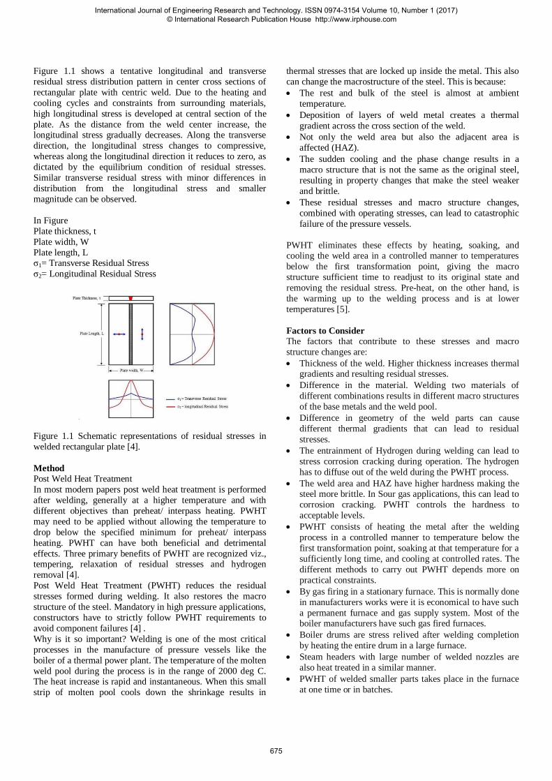
Figure 1.1 shows a tentative longitudinal and transverse
residual stress distribution pattern in center cross sections of
rectangular plate with centric weld. Due to the heating and
cooling cycles and constraints from surrounding materials,
high longitudinal stress is developed at central section of the
plate. As the distance from the weld center increase, the longitudinal stress gradually decreases. Along the transverse
direction, the longitudinal stress changes to compressive,
whereas along the longitudinal direction it reduces to zero, as
dictated by the equilibrium condition of residual stresses.
Similar transverse residual stress with minor differences in
distribution from the longitudinal stress and smaller
magnitude can be observed.
In Figure
Plate thickness, t
Plate width, W
Plate length, L σ1= Transverse Residual Stress
σ2= Longitudinal Residual Stress
Figure 1.1 Schematic representations of residual stresses in
welded rectangular plate [4].
Method
Post Weld Heat Treatment
In most modern papers post weld heat treatment is performed
after welding, generally at a higher temperature and with
different objectives than preheat/ interpass heating. PWHT
may need to be applied without allowing the temperature to
drop below the specified minimum for preheat/ interpass
heating. PWHT can have both beneficial and detrimental
effects. Three primary benefits of PWHT are recognized viz., tempering, relaxation of residual stresses and hydrogen
removal [4].
Post Weld Heat Treatment (PWHT) reduces the residual
stresses formed during welding. It also restores the macro
structure of the steel. Mandatory in high pressure applications,
constructors have to strictly follow PWHT requirements to
avoid component failures [4] .
Why is it so important? Welding is one of the most critical
processes in the manufacture of pressure vessels like the
boiler of a thermal power plant. The temperature of the molten
weld pool during the process is in the range of 2000 deg C. The heat increase is rapid and instantaneous. When this small
strip of molten pool cools down the shrinkage results in
thermal stresses that are locked up inside the metal. This also
can change the macrostructure of the steel. This is because:
The rest and bulk of the steel is almost at ambient
temperature.
Deposition of layers of weld metal creates a thermal
gradient across the cross section of the weld.
Not only the weld area but also the adjacent area is
affected (HAZ).
The sudden cooling and the phase change results in a
macro structure that is not the same as the original steel,
resulting in property changes that make the steel weaker
and brittle.
These residual stresses and macro structure changes,
combined with operating stresses, can lead to catastrophic
failure of the pressure vessels.
PWHT eliminates these effects by heating, soaking, and cooling the weld area in a controlled manner to temperatures
below the first transformation point, giving the macro
structure sufficient time to readjust to its original state and
removing the residual stress. Pre-heat, on the other hand, is
the warming up to the welding process and is at lower
temperatures [5].
Factors to Consider
The factors that contribute to these stresses and macro
structure changes are:
Thickness of the weld. Higher thickness increases thermal gradients and resulting residual stresses.
Difference in the material. Welding two materials of
different combinations results in different macro structures
of the base metals and the weld pool.
Difference in geometry of the weld parts can cause
different thermal gradients that can lead to residual
stresses.
The entrainment of Hydrogen during welding can lead to
stress corrosion cracking during operation. The hydrogen
has to diffuse out of the weld during the PWHT process.
The weld area and HAZ have higher hardness making the steel more brittle. In Sour gas applications, this can lead to
corrosion cracking. PWHT controls the hardness to
acceptable levels.
PWHT consists of heating the metal after the welding
process in a controlled manner to temperature below the
first transformation point, soaking at that temperature for a
sufficiently long time, and cooling at controlled rates. The
different methods to carry out PWHT depends more on
practical constraints.
By gas firing in a stationary furnace. This is normally done
in manufacturers works were it is economical to have such
a permanent furnace and gas supply system. Most of the boiler manufacturers have such gas fired furnaces.
Boiler drums are stress relived after welding completion
by heating the entire drum in a large furnace.
Steam headers with large number of welded nozzles are
also heat treated in a similar manner.
PWHT of welded smaller parts takes place in the furnace
at one time or in batches.
International Journal of Engineering Research and Technology. ISSN 0974-3154 Volume 10, Number 1 (2017) © International Research Publication House http://www.irphouse.com
675
By gas firing or electrical heating in temporary furnaces.
This avoids cost in transporting the finished products from
fabrication location to facilities that have fixed furnaces.
Localized PWHT. Construction sites and fabrication shops
use this method.
The most common method is by electrical resistance heating. Ceramic beaded heating coils are wound over the
weld area. The current controls the temperature gradients.
Induction heating is one method that is gaining popularity
even though the cost is high. This is a more welder
friendly process. Unlike resistance heating only the pipe
becomes hot. The temperature gradients are uniform
across the thickness.
By internal gas firing. Large vessels, columns, spherical
tanks, sour tanks, etc. are heat treated by firing gas
internally. This requires special equipment and skilled
contractors and is a much more elaborate process. Thermal expansion of the vessel has to be considered during the
PWHT process.
Thermocouples on the surface measure and record the
temperatures during PWHT. This recording is a must and
is the only record of the heat treatment having been done
[5].
Recipe for welding simulations
During the welding, complicated phenomenon such as
temperature dependency of material properties, phase
transformation (melting and evaporation) occurs for short time
in localized region. Further, the stress/strain development
during the welding is complex to visualize, since it is a three
dimensional time and temperature dependent problem.
Although, the experimental investigations provide valuable
insights into the process of welding, many experimental
techniques are complex and expensive and some quantities,
such as the transient stress/strain development during welding,
cannot be measured at all. Furthermore, traditional trial and
error approach based on costly and time consuming welding
experiments encounters hindrance to sound welds due to
welding process parameters optimization. In order to get an
appropriate insight into the process, extend the application of
welding process on shop floor level with reliability and cost
effectiveness, appropriate control techniques are mandatory.
A synergistic approach involving both finite element
modeling and experimental work has proven very useful
Numerical simulations based on finite element (FE) models
provide a very suitable tool for investigating the thermal and
mechanical consequences of welding process. The availability
of 64-bit high performance computing machines and enhanced
finite element computational techniques has made it possible
to simulate temperature fields developed from welding
process. In contrast to experimental investigations, finite
element models allow an extensive variation of welding
process and heat source parameters, without having to deal
with the practical limitations. The finite element models can
be used for detailed studies of temperature and stress/strain
during and after the welding thereby improving the
understanding of the process. Once, the models have been
validated, the results from the simulations can be used to
demonstrate the physical essence of complex phenomenon in
welding processes explicitly and can be utilized as the basis
for welding process optimization. The computer simulation of
welding processes enables the welding engineers to predict
residual stress fields of welded structures. However, the
simulation of welding process altogether is not a simple
computational task due to the involvement of multi field
interaction like thermal, mechanical and metallurgy. Also the
filler metal deposition, moving heat source, material behavior
at elevated temperature along with geometric nonlinearities
made it even more complex manufacturing task for finite
element community engaged in materials and processes
modeling. Several commercially available finite element
codes such as ANSYS®, ABAQUS®, FEMLAB®, MSC
MARC®, ADINA® and SYSWELD® etc. are available
which can be employed to carry out such type of
manufacturing processes simulations [6].
In the current project work i have used ANSYS® for
simulation. Its coding comprises elements
activation/deactivation functionality, meshing algorithm, heat
source modeling, material models, heat flux distribution as per
analytical model and material properties management
depending on the temperature reached in elements etc. To
simplify the simulation procedure, generally recognized finite
element simulation of welding process requiring; transient
thermal analysis and structural analysis is employed.
1.1. Preamble
This report describes the modeling and analysis of PWHT of
Nozzle insulation ring. The weld for insulation ring was
modified locally and PWHT is carried out locally. Therefore
to check the effect of local PWHT, Finite element analysis is
performed [7].
1.2. Analysis Details
The PWHT analysis is carried out as per below details,
Rate of Heating above 300 0C : 56 0C /hr
Holding Temperature : 690 0C +/- 10 0C
Holding time : 8 hr
Rate of Cooling upto 300 0C /hr : 56 0C /hr
1.3. Local PWHT Details
Rate of Heating above 300 0C : 56 0C /hr
Holding Temperature : 690 0C +/- 10 0C
Holding time : 5.5 hr
Rate of Cooling upto 300 0C /hr : 56 0C /hr
International Journal of Engineering Research and Technology. ISSN 0974-3154 Volume 10, Number 1 (2017) © International Research Publication House http://www.irphouse.com
676
1.4. Material of construction
Material of construction considered for FEA analysis is as
given below:
Channel Barrel : SA 336 Gr. F22 CL3
Nozzle N3 : SA 336 Gr. F22 CL3
Insulation Ring : SA 387 Gr. 22 CL2
1.5. Material properties
ASME Sec II Part D, Ed. 2013 is referred for physical
properties of materials as follows
Material Design
temp
( 0C )
Modulus
of
elasticity
(MPa)
Allowable
stress
(MPa)
Yield
stress
(MPa)
SA 336
Gr. F22
CL3
395 184400 161.4 241.8
FINITE ELEMENT MODEL
Software description:
The finite element analysis software used for performing
analysis is ANSYS Mechanical APDL16.0 developed by
ANSYS Inc. USA. The software runs on windows 7 operating
system.
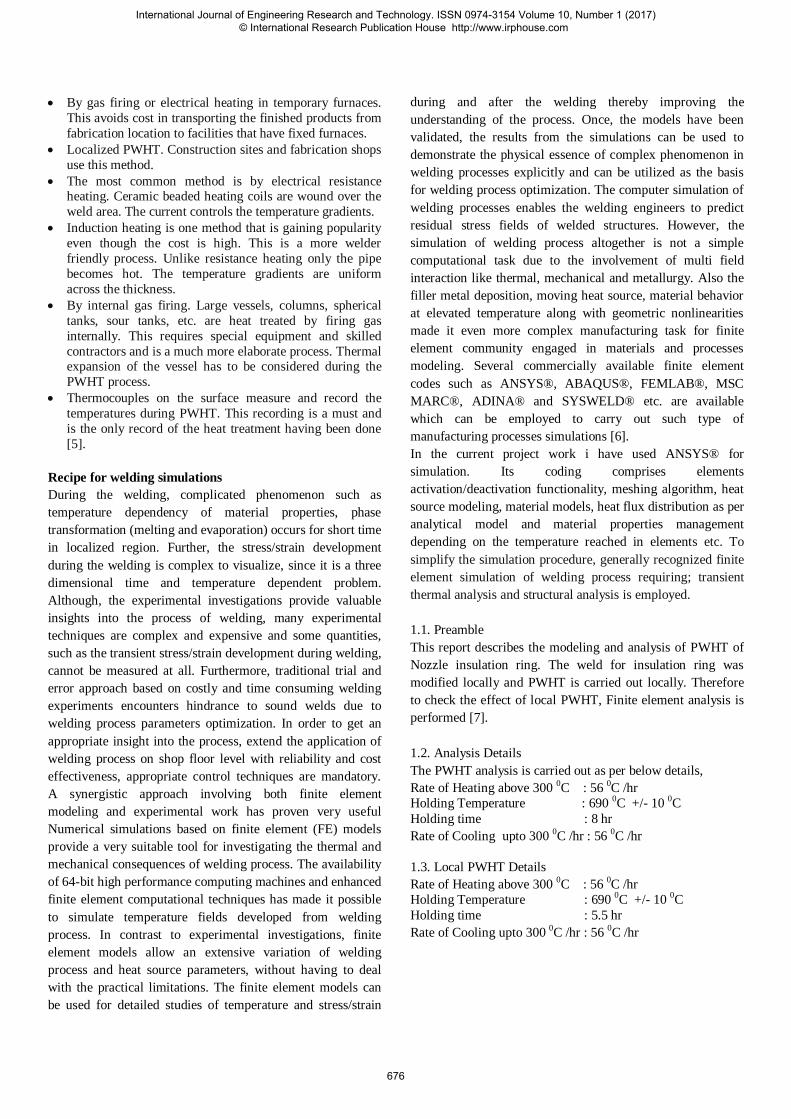
Modeling data:
3D geometry is created as per the dimensions given in
following drawings-
General Arrangement drawing ,
Design Data, Detailed Fabrication drawing .
Figure 2-1 3D Model
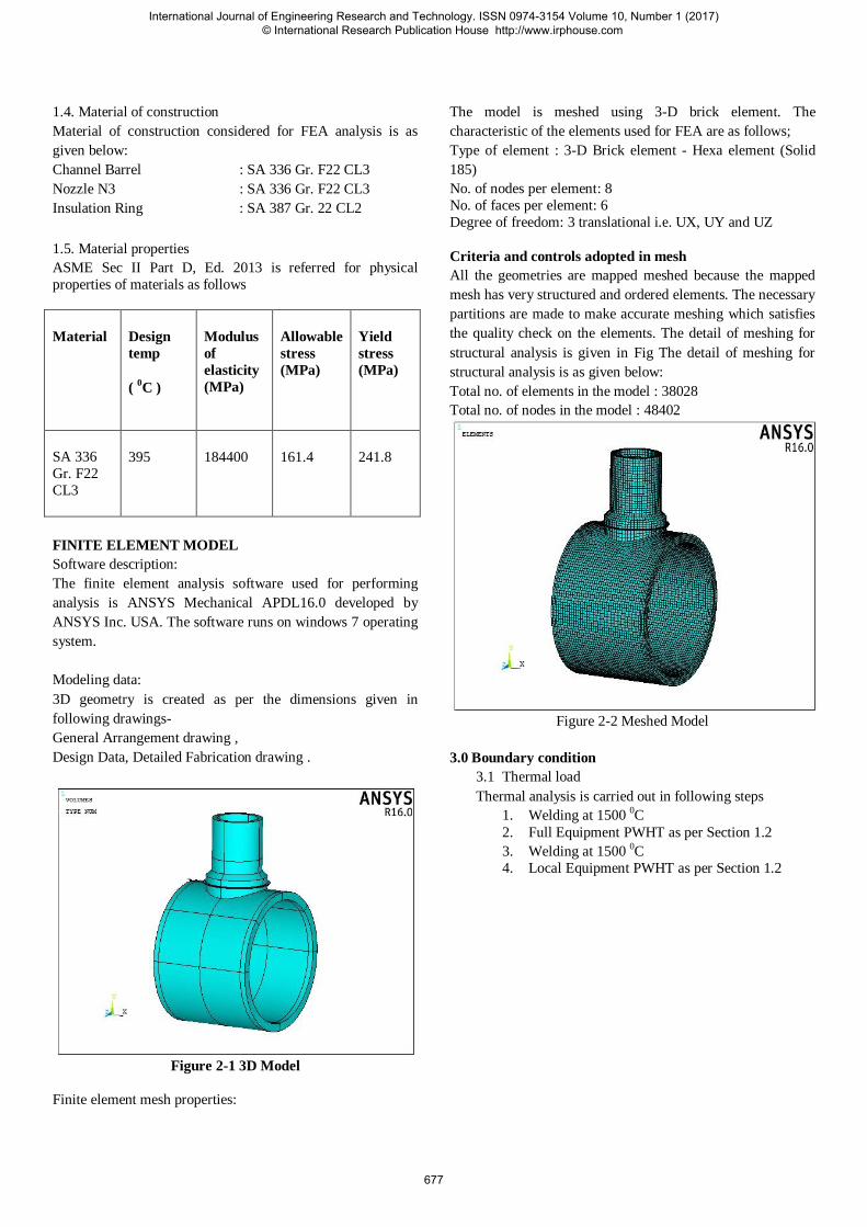
Finite element mesh properties:
The model is meshed using 3-D brick element. The
characteristic of the elements used for FEA are as follows;
Type of element : 3-D Brick element - Hexa element (Solid
185)
No. of nodes per element: 8
No. of faces per element: 6
Degree of freedom: 3 translational i.e. UX, UY and UZ
Criteria and controls adopted in mesh
All the geometries are mapped meshed because the mapped
mesh has very structured and ordered elements. The necessary
partitions are made to make accurate meshing which satisfies
the quality check on the elements. The detail of meshing for
structural analysis is given in Fig The detail of meshing for
structural analysis is as given below:
Total no. of elements in the model : 38028
Total no. of nodes in the model : 48402
Figure 2-2 Meshed Model
3.0 Boundary condition
3.1 Thermal load
Thermal analysis is carried out in following steps
1. Welding at 1500 0C
2. Full Equipment PWHT as per Section 1.2
3. Welding at 1500 0C
4. Local Equipment PWHT as per Section 1.2
International Journal of Engineering Research and Technology. ISSN 0974-3154 Volume 10, Number 1 (2017) © International Research Publication House http://www.irphouse.com
677
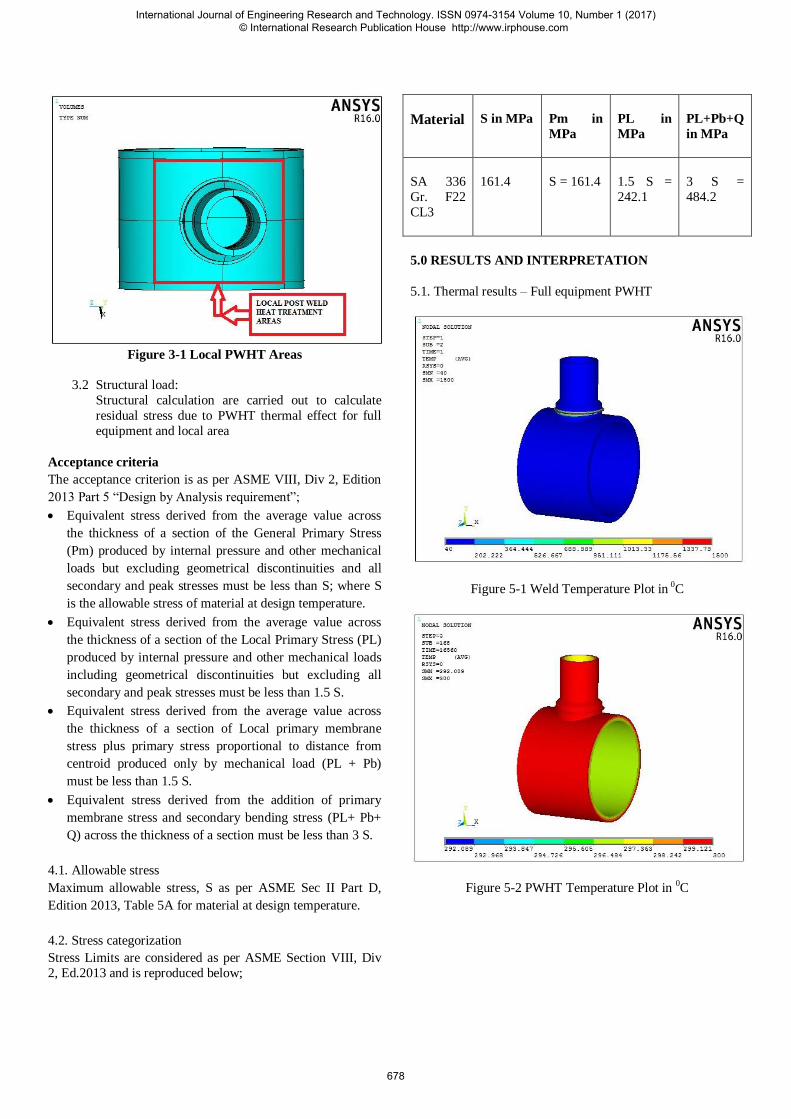
Figure 3-1 Local PWHT Areas
3.2 Structural load:
Structural calculation are carried out to calculate
residual stress due to PWHT thermal effect for full
equipment and local area
Acceptance criteria
The acceptance criterion is as per ASME VIII, Div 2, Edition
2013 Part 5 “Design by Analysis requirement”;
Equivalent stress derived from the average value across
the thickness of a section of the General Primary Stress
(Pm) produced by internal pressure and other mechanical
loads but excluding geometrical discontinuities and all
secondary and peak stresses must be less than S; where S
is the allowable stress of material at design temperature.
Equivalent stress derived from the average value across
the thickness of a section of the Local Primary Stress (PL)
produced by internal pressure and other mechanical loads
including geometrical discontinuities but excluding all
secondary and peak stresses must be less than 1.5 S.
Equivalent stress derived from the average value across
the thickness of a section of Local primary membrane
stress plus primary stress proportional to distance from
centroid produced only by mechanical load (PL + Pb)
must be less than 1.5 S.
Equivalent stress derived from the addition of primary
membrane stress and secondary bending stress (PL+ Pb+
Q) across the thickness of a section must be less than 3 S.
4.1. Allowable stress
Maximum allowable stress, S as per ASME Sec II Part D,
Edition 2013, Table 5A for material at design temperature.
4.2. Stress categorization
Stress Limits are considered as per ASME Section VIII, Div
2, Ed.2013 and is reproduced below;
Material S in MPa Pm in
MPa
PL in
MPa
PL+Pb+Q
in MPa
SA 336
Gr. F22
CL3
161.4 S = 161.4 1.5 S =
242.1
3 S =
484.2
5.0 RESULTS AND INTERPRETATION
5.1. Thermal results – Full equipment PWHT
Figure 5-1 Weld Temperature Plot in 0C
Figure 5-2 PWHT Temperature Plot in 0C
International Journal of Engineering Research and Technology. ISSN 0974-3154 Volume 10, Number 1 (2017) © International Research Publication House http://www.irphouse.com
678
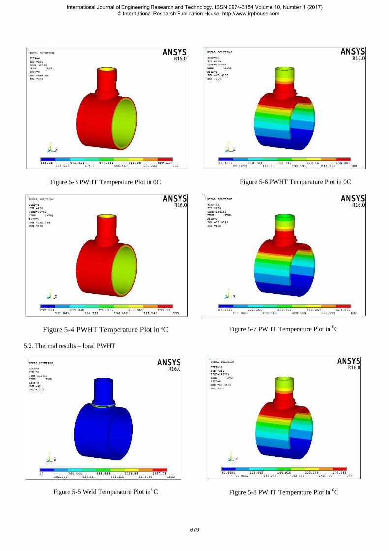
Figure 5-3 PWHT Temperature Plot in 0C
Figure 5-4 PWHT Temperature Plot in 0C
5.2. Thermal results – local PWHT
Figure 5-5 Weld Temperature Plot in 0C
Figure 5-6 PWHT Temperature Plot in 0C
Figure 5-7 PWHT Temperature Plot in 0C
Figure 5-8 PWHT Temperature Plot in 0C
International Journal of Engineering Research and Technology. ISSN 0974-3154 Volume 10, Number 1 (2017) © International Research Publication House http://www.irphouse.com
679
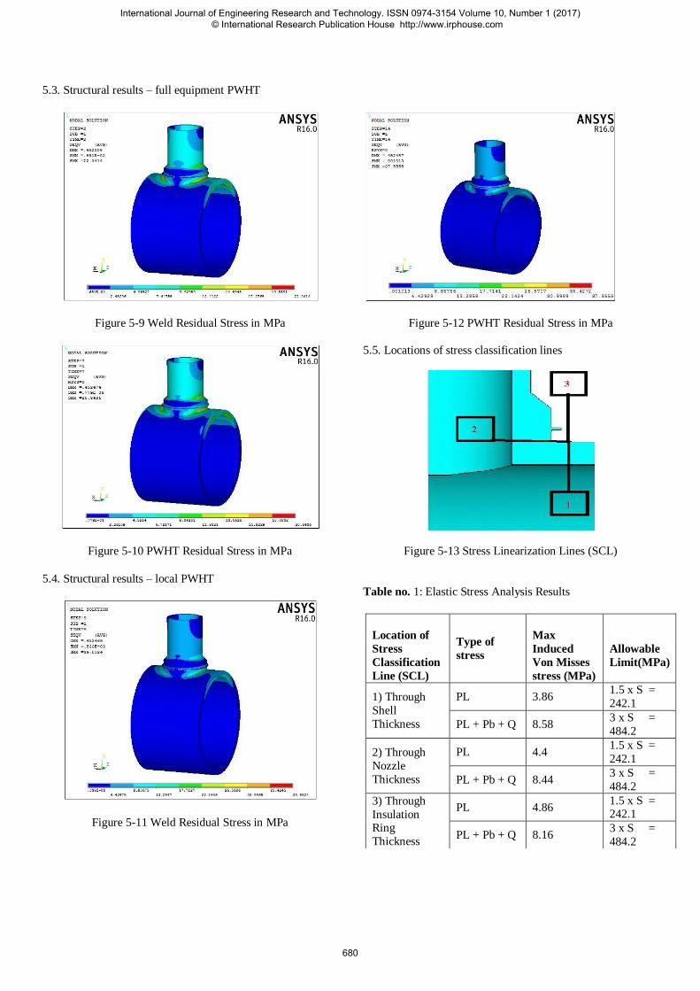
5.3. Structural results – full equipment PWHT
Figure 5-9 Weld Residual Stress in MPa
Figure 5-10 PWHT Residual Stress in MPa
5.4. Structural results – local PWHT
Figure 5-11 Weld Residual Stress in MPa
Figure 5-12 PWHT Residual Stress in MPa
5.5. Locations of stress classification lines
Figure 5-13 Stress Linearization Lines (SCL)
Table no. 1: Elastic Stress Analysis Results
Location of
Stress
Classification
Line (SCL)
Type of
stress
Max
Induced
Von Misses
stress (MPa)
Allowable
Limit(MPa)
1) Through
Shell
Thickness
PL 3.86 1.5 x S =
242.1
PL + Pb + Q 8.58 3 x S =
484.2
2) Through
Nozzle
Thickness
PL 4.4 1.5 x S =
242.1
PL + Pb + Q 8.44 3 x S =
484.2
3) Through
Insulation Ring
Thickness
PL 4.86 1.5 x S = 242.1
PL + Pb + Q 8.16 3 x S =
484.2
International Journal of Engineering Research and Technology. ISSN 0974-3154 Volume 10, Number 1 (2017) © International Research Publication House http://www.irphouse.com
680
Table no. 2: Final result full equipment PWHT and Local
PWHT.
Condition Process Residual
Stress
(MPa)
PWHT Stress
Relaxation
(MPa)
1)Full
Equipment PWHT
Weld 22.34
2 PWHT 20.34
2) Local
PWHT
Weld 39.85
2 PWHT 37.85
Conclusion The following conclusions were arrived at after analyzing the
PWHT process for material Channel Barrel: SA 336 Gr. F22
CL3, Nozzle N3: SA 336 Gr. F22 CL3, Insulation Ring: SA
387 Gr. 22 CL2. The Welding process was simulated using
ANSYS 16 Software. We conclude that when PWHT analysis
is carried out for complete equipment and after some
modification in the fabrication of the equipment if welding is
carried out again there is no need to carry out PWHT again for
complete equipment instead PWHT for localized area. Where
welding process is carried out will reduce the residual stress.
The post weld heat treatment gives 2 MPa relaxation to the
residual stresses over welding processes on full equipment
PWHT and local PWHT as well.
References
[1] Mr. Varma Prasad V.M., Joy Varghese V.M., Suresh
M.R., Siva Kumar D., “3D simulation of residual stress
developed during TIG welding of stainless steel pipes.”,
International Conference on Emerging Trends in
Engineering, Science and Technology, ISSN 2212-0173,
pp. (364-371), 2016.
[2] Hun-CheaJunga, Sa-WoongKima, Yun-HeeLeeb, Seung-
WookBaekc, Min-Su Haa,Hee-Jin Shimaa “Investigation
of effect of post weld heat treatment conditions on
residual stress for ITER blanket shield blocks”, ELESEVIER, G model fusion-8524, ISSN 01920-3796,
pp. 1-5, 2016.
[3] Pingsha Dong, Shaopin Song, Jinmiao Zhang, “Analysis
of residual stress relief mechanisms in post-weld heat
treatment”, International Journal of Pressure Vessels and
Piping 122 6e14 ELESEVIER , ISSN 0308-01641, pp. 6-
14, 2014.
[4] Yi Han, Enlin Yu, Daochen Huang,Liang Zhang,
“Simulation and Analysis of Residual Stress and
Microstructure Transformation for Post Weld Heat Treatment of a Welded Pipe” , Journal of Pressure Vessel
Technology Copyright VC by ASME, Vol. 136 / 021401-
1021401-2 / Vol. 136, 2014.
[5] K. Abburi Venkataa, S. Kumarb, H. C. Deyc, D. J.
Smitha, P. J. Bouchardd and C. E. Trumana “Study on the
Effect of Post Weld Heat Treatment Parameters on the
Relaxation of Welding Residual Stresses in Electron
Beam Welded P91 Steel Plates”, International
Conference on Structural Integrity, ELESEVIER, ISSN 1877-7058, pp. 223-233, 2014.
[6] Ergun Nart, Yukselcelik, “A practical approach for
simulating submerged arc welding process using FE
method”, ELESEVIER, ISSN 0143-974X, pp.62-71,
2013.
[7] S. Paddeaa, J.A. Francisb, A.M. Paradowskac, P.J.
Boucharda, I.A. Shibli d, “Residual stress distributions in
a P91 steel-pipe girth weld before and after post weld
heat treatment”, Materials Science and Engineering,
ELESEVIER, ISSN 0921-563, pp. 663– 672, 2012.
International Journal of Engineering Research and Technology. ISSN 0974-3154 Volume 10, Number 1 (2017) © International Research Publication House http://www.irphouse.com
681