Embed Size (px)
Citation preview

DOI: 10.23883/IJRTER.2017.3183.SIP3H 535
DESIGN AND OPTIMIZATION OF EXCAVATOR
G.Ramesh1 , V.N.Krishnareddy
2, T. Ratnareddy
3
1,2 P.G. Student, Mechanical Engineering Dept., Chaitanya Bharathi Institute of Technology,
Hyderabad- 75,AndraPradesh,India. 3Prof Mechanical Engineering Dept., Chaitanya Bharathi Institute of Technology, Hyderabad-75,
Andhra Pradesh, India.
Abstract-The hydraulic excavators are one of the earth movers playing a major role in the
development of the infrastructure like excavation, road construction, building construction, granite
mining, ore mining, Coal mining etc. Excavators are generally equipped with a work implement or
attachment for performing useful work. Such attachments include digging and material handling
buckets, drills, and hydraulic hammers. To reduce number of iterations during the development
process, the computational simulation method is used in Excavator for Multi Body Simulation
analysis. An explicit finite element code like Altair Radioss is used for the simulation. Optimization
is carried out to improve the Lower arm Excavator model to get less weight and stiffest component.
This paper explains the FE analysis of Excavator of Lower Arm. All the results obtained from the
CAE analysis are evaluated against the requirements which could reduce the process development
time and cost. Aim of the Project is to Design and do Multi Body Simulation analysis for Excavator
and Perform Topology Optimization to reduce the Weight of the Lower Arm Excavator. Catia V5
R19 for modeling Excavator and Preprocessing in Hyper mesh and Radioss for solving results are
viewed in Hyper view. Altair Optistruct is used for weight reduction and change in design of
Excavator of Lower Arm.
Keywords –Excavator, Radioss, CAE Analysis, Topology Optimization ,Altair Hyper mesh.
I. INTRODUCTION The development of new hydraulic excavators of the medium class that have embodied various
design concepts like an IT technology, safety and global environment, basic performance, etc.
Named hydraulic excavators in KOMATSU Series, the new machines have been introduced in the
world markets with success. This paper takes up one of them, PC200-7, as a sample to explain the
background of the development, the technology that sustains the design concepts and features of the
product.
(1) To provide our customers with solutions to their problems through making the most of available
IT (Information Technology)
(2) To help alleviate the environmental burden on the earth
(3) To help establish safer working environment
(4) To provide high basic performance and quality of machine
that are tenable worldwide.
Those concepts were further developed into the following seven items of concepts for new hydraulic
excavators in KOMATSU Series.
(1) Basic performance
To establish compatibility a large production and low fuel Consumption
(2) Comfort ability
To assure a comfortable environment in the operator's cab with a low noise level and little vibration.
(3) Global environment

International Journal of Recent Trends in Engineering & Research (IJRTER)
Volume 03, Issue 04; April - 2017 [ISSN: 2455-1457]
@IJRTER-2017, All Rights Reserved 536
To mount an engine of clean gas emission and low noises
(4) Safety
To clear safety standard in each country
Fig1: KOMATSU Excavator Motion
As per the motion shown in the above figure excavator is carried out time related motion to the
Boom, Boom Cylinder, Arm, Arm Cylinder and Bucket. These are the designs are generated a three
dimensional model using CATIA V5R19 Software. Then imported in to Altair Hyper mesh for
preprocessing, Radioss is to run the motion simulation for 1second time.
Research objectives The main objectives of the proposed research work are as follows:
� Design of the backhoe excavator attachment for light duty construction work that has The higher
kinematic working ranges with optimum dimensions and can be applicable for autonomous
excavation task.
� to develop a mathematical kinematic model for four degrees of freedom backhoe mechanism to
study the motion of backhoe attachment.
� to develop a mathematical dynamic model for digging mode having three degree of freedom
(excluding the first degree of freedom that is swing motion). The proposed dynamic model used to
predict dynamic forces developed during the digging task and also helpful to design controller to get
controlled motion of backhoe attachment. It means it can be applicable for autonomous application
for excavation task.
� To perform structural weight optimization of backhoe attachment using FEA approach without
compromise in strength to reduce the weight to cost ratio.
Project Objective The objective of the problem is to get the less weight design of Lower Arm using latest technology
software’s like Altair Hyper mesh, Radioss and Optistruct software.
Modeling Using CATIA V5R19 This thesis ford car 3d model is designed using CATIA V5 R19 Software. This software used in
automobile, aerospace, consumer goods, heavy engineering, etc... Catia V5 R19 is very powerful
software for designing complicated 3d models.
CATIA - Automotive Body-In-White Fastening 3 (ABF) is dedicated to the design of Automotive
Body In White Fasteners. It supports Welding technologies and mechanical clinching along
withAdhesives,Sealer,andMastics.
The same CATIA V5 R19 3d model and 2d drawing model is shown below for reference.
Dimensions are taken from KOMATSU OEM. The design of 3d model is done in Catia v5r19
software, and then to do test we are using below mentioned software’s.
Drawing Files are mentioned below based on original component, Using Catia V5 R19 Software will
International Journal of Recent Trends in Engineering & Research (IJRTER)
Volume 03, Issue 04; April - 2017 [ISSN: 2455-1457]
@IJRTER-2017, All Rights Reserved 537
developed excavator Lower arm, Boom, Bucket and holders of lower and boom component.
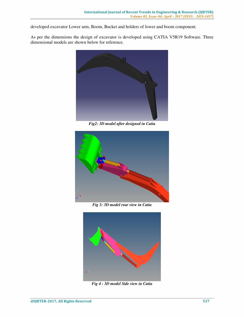
As per the dimensions the design of excavator is developed using CATIA V5R19 Software. Three
dimensional models are shown below for reference.
Fig2: 3D model after designed in Catia
Fig 3: 3D model rear view in Catia
Fig 4 : 3D model Side view in Catia

International Journal of Recent Trends in Engineering & Research (IJRTER)
Volume 03, Issue 04; April - 2017 [ISSN: 2455-1457]
@IJRTER-2017, All Rights Reserved 538
Fig5 : 3D model Top view in Catia
Three dimensional model is designed in Catia v5 r19 software and then generated 2 dimensions are
generated the same is shown in above figures.
Next after designing the model we need to do testing on the assembly components, for that we need
to select the software for finite element analysis and then optimization is carried out for the lower
arm of the excavator. Optimization removes the unwanted material in the component and then it is
gives us innovative shape. After that we need to check the comparison of displacement and weight
of the two lower arm components.
II. PREPROCESSING OF EXCAVATOR
CATIA 3D Model CATIA 3D model, we are importing in to Altair Hyper mesh for preprocessing, for solving we are
using Altair Radioss software and for viewing the results Altair Hyper view. Due to huge weight of
lower arm of excavator, we are taking complete lower arm for Optimization to achieve the less
weight of the model and to get concept shape of lower arm.
For above analysis methodology and to check strength of lower arm, we need to check stiffness of
the frame using different approaches. As per Automobile OEM’s (Original equipment manufacturer)
to check strength of excavator motion, physically they will apply force like digging. The same
physical problem is prepared in Altair Hyper mesh for solving the motion analysis.
Virtual Analysis is carried out in Radioss to check the displacement acting while digging of bucket
what is the effect at the lower arm and how to remove unwanted material for lower arm is carried out
using Altair Optistruct.
The model is Meshed with the hexapenta mesh using Altair Hyper mesh. Below figure shows
complete assembly component is meshed.

International Journal of Recent Trends in Engineering & Research (IJRTER)
Volume 03, Issue 04; April - 2017 [ISSN: 2455-1457]
@IJRTER-2017, All Rights Reserved 539
Fig 6: 3D model Side view which is meshed using Hyper mesh
Fig 7: 3D model Zoom view which is meshed using Hyper mesh
Material Collector
Fig 8: Excavator Material is Steel
Fig 9: Excavator Steel Material Mechanical Properties

International Journal of Recent Trends in Engineering & Research (IJRTER)
Volume 03, Issue 04; April - 2017 [ISSN: 2455-1457]
@IJRTER-2017, All Rights Reserved 540
Fig 10: Excavator Arm Control Coupler is highlighted
Fig 11: Excavator Bucket is highlighted
Fig 12: Excavator Lower Arm is highlighted for updating PSOLID property.

International Journal of Recent Trends in Engineering & Research (IJRTER)
Volume 03, Issue 04; April - 2017 [ISSN: 2455-1457]
@IJRTER-2017, All Rights Reserved 541
III. BOUNDARY CONDITIONS
Constraints:
Fig 13: Excavator Lower Arm is fixed at the coupler of Bucket in All DOF
Motion: Here in this thesis we are solving Multi Body Simulation analysis this is also called as
transient analysis which is related to time dependent problem.
Time input is mentioned in above figure is 1second, for 1 second excavator motion is carried out and
checked for displacement value for the motion. Type of analysis is mentioned in above figure is
Transient.
Fig 14: Excavator is solved for MOTION which is mentioned in load collector
For Kinematic analysis we need to apply the joints at particular location based on the moments of
excavator. Joints applied are shown below for reference.
Fig 15: Joints are applied for Excavator for Kinematic (Revolute and Translate Joints)
Excavator is solved for MOTION, for which joints are applied in above figure clearly shown at what
location revolute and translate joint is applied.
Joints applied using Hyper mesh, which will be available in 1D page. We have all varieties of joints
in 1D-Page –Joints which are shown below for reference.

International Journal of Recent Trends in Engineering & Research (IJRTER)
Volume 03, Issue 04; April - 2017 [ISSN: 2455-1457]
@IJRTER-2017, All Rights Reserved 542
Fig 16: Joints are applied for Excavator using 1D Page in Hyper mesh
Fig 17: Number of nodes and Elements shown in Hyper mesh
Fig 18: Multi Body Simulation is solved using Altair Radioss Solver
Save the particular model is a directory and click on Radioss on right side which is executing button
to start the analysis of Multi Body Simulation.
After results getting completed the window shows that the job is completed then we need click on
Hyper view executing button as per above figure and then Post processing window will be opening
in another window. In that we can see the displacement of excavator and motion of excavator.
Weight of complete assembly and Lower Arm is shown below which is measured before
optimization of Lower Arm model.
Fig 19: Weight of Complete Excavator Design which is about 1888 tons.

International Journal of Recent Trends in Engineering & Research (IJRTER)
Volume 03, Issue 04; April - 2017 [ISSN: 2455-1457]
@IJRTER-2017, All Rights Reserved 543
Fig 20: Weight of Lower Arm Design which is about 343 tons.
After seeing the results of first model then as per the objective of the thesis we need to remove
unwanted material from Lower arm which is very important to reduce the weight and it should be
more stiffer because when excavator lift or dig the load will more at the lower arm location for that
purpose. To get stiffest structure shape we choose the Optistruct software for getting innovative
shape for lower arm.
After getting the results will compare the results of optimization model weight and displacement.
IV. OPTISTRUCT PROCEDURE
Optimization • Increases competitiveness through product innovation
• Provides an easy-to-use graphical user interface and tight application integration that maximizes
end-user efficiency
• Leads the industry with the ability to solve the largest, most complex optimization problems.
First- in-industry, innovative method, allows for the multi-disciplinary optimization of designs with
non-linear behavior and system-level multi-body dynamic models. Additionally ESLM can be
applied to concept design synthesis and design fine-tuning.
The same method is used for Lower Arm of excavator design and solved using Equivalent Static
Load Method, for which we need to give inputs in Optistruct deck.
Procedure for deck preparation in Optistruct is shown below:
Fig 21: User profile in Hyper mesh Window
The first step to start the optimization deck preparation, change the user profile to Optistruct and in
that optimization template will generated at the background of hyper mesh and then application of
optimization tool will be available in analysis page optimization in which various different
optimization techniques are available in that we are using topology optimization. This will help us to
remove unwanted material based on the loading conditions.

International Journal of Recent Trends in Engineering & Research (IJRTER)
Volume 03, Issue 04; April - 2017 [ISSN: 2455-1457]
@IJRTER-2017, All Rights Reserved 544
Fig 22: Topology Optimization Setup
In the above figure topology optimization option is selected and in that we need to give design
variable name is required which we have mentioned L-Arm_Toplogy and then slected PSOLID as a
element property which we have selected is lower arm.
Fig 23 : Weight Optimization is mentioned in the response
After that next step is to give a response for the Lower Arm model by which it will do internally
iteration by iteration for the given response optimization will be generated a new shape to us.
Fig 24: Volume fraction Optimization is mentioned in the response for Lower Arm
Fig 25: Volume fraction Optimization is mentioned in the DCONSTRAINT is about 0.5(50%)
The value which we mentioned in the upper bound is nothing but percentage of volume which should
be removed from the model.
Fig 26: Objective for Lower Arm in Optimization to minimize or maximize the volume
International Journal of Recent Trends in Engineering & Research (IJRTER)
Volume 03, Issue 04; April - 2017 [ISSN: 2455-1457]
@IJRTER-2017, All Rights Reserved 545
By all the above steps optimization steps are completed now directly will go to Analysis page and
then to solve Optistruct we need to select Optistruct from analysis page and click on executing button
of Optistruct. It will solve the problem as per the given inputs in above steps; this will take few
minutes to solve the problem which will be doing by iteration process.
All the results of modified model and base model results are shown in Results chapter.
Results and Discussions
Base model is carried out using Altair Radioss software which is solved the same results for the base
design is shown for reference.
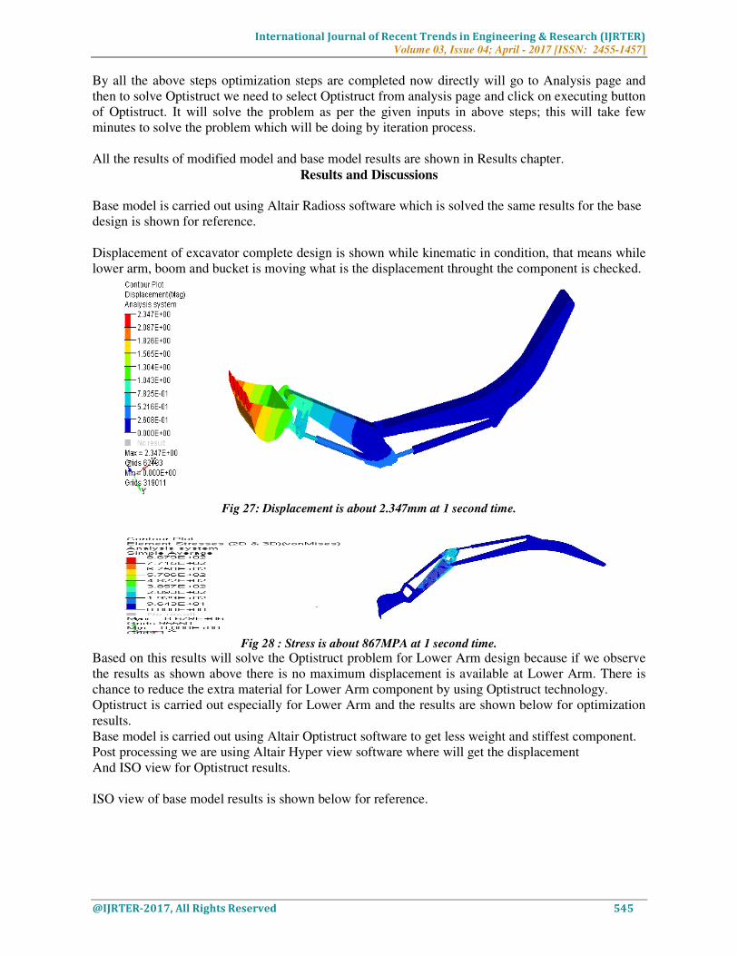
Displacement of excavator complete design is shown while kinematic in condition, that means while
lower arm, boom and bucket is moving what is the displacement throught the component is checked.
Fig 27: Displacement is about 2.347mm at 1 second time.
Fig 28 : Stress is about 867MPA at 1 second time.
Based on this results will solve the Optistruct problem for Lower Arm design because if we observe
the results as shown above there is no maximum displacement is available at Lower Arm. There is
chance to reduce the extra material for Lower Arm component by using Optistruct technology.
Optistruct is carried out especially for Lower Arm and the results are shown below for optimization
results.
Base model is carried out using Altair Optistruct software to get less weight and stiffest component.
Post processing we are using Altair Hyper view software where will get the displacement
And ISO view for Optistruct results.
ISO view of base model results is shown below for reference.

International Journal of Recent Trends in Engineering & Research (IJRTER)
Volume 03, Issue 04; April - 2017 [ISSN: 2455-1457]
@IJRTER-2017, All Rights Reserved 546
Fig 29: Hyper view window to see the displacement and ISO View of Lower Arm
Fig 30: Optimization of Lower Arm ISO View Image
After seeing the results of ISO view this model shape should be designed in cad or hyper mesh itself.
In Hyper mesh OS Smooth tool is available it will generate the OS Smooth optimized shape which
we got for Optistruct analysis.
New design is generated using internal tool of hyper mesh which is called as OS Smooth, by which
will get a new shape. In which it has been removed the unwanted material from the Lower Arm.
The same model is shown below after OS Smooth option.
Fig 31: OS Smooth Model
By which meshing will remain same and no need of meshing again to the component directly for the
same loading conditions of base model about 1 second we are solving multi body simulation to check
the displacement of optimized model is carried out.
Fig 32: For OS Smooth Model Radioss is used for MBD simulation about 1 second

International Journal of Recent Trends in Engineering & Research (IJRTER)
Volume 03, Issue 04; April - 2017 [ISSN: 2455-1457]
@IJRTER-2017, All Rights Reserved 547
Fig33: Displacement is about 2.348mm at 1 second time for Second Design
Fig 34: Stress is about 987MPA at 1 second time for Second Design
Fig 35: Number of nodes and elements for design 2
Nodes are about 173030 and elements are 100885. The same way for the first design is about 175780
nodes and elements are 102686.
If we compare the weight of the design1 and design will get the difference, first design weight is
about total model weight is 1888 tons. Only for Lower Arm of first design is about 343.793 tons. For
the new design 2 complete weight of the model is about 1857 tons and for Lower Arm weight is
about 311.865 tons.

International Journal of Recent Trends in Engineering & Research (IJRTER)
Volume 03, Issue 04; April - 2017 [ISSN: 2455-1457]
@IJRTER-2017, All Rights Reserved 548
Fig 36 : Optimized Complete Design model weight is about 1857 tons
Fig 37: Optimized Lower Arm Design model weight is about 311.865 tons
Finally results are shown for first base design 1 and optimized model design 2, all are got concluded
in next chapter.
comparison of weight, displacement, stress is compared in chapter conclusions.
Stress and Displacement comparison Of Two Models: Table1: Stress and Displacement comparison of base model and optimized model.
WEIGHT REDUCTION AND COMPARISON OF LOWER ARM MODEL
Table 2: Weight comparison of base model and optic model of Lower Arm
MODEL TYPE Weight Of The Lower Arm
Base Model
343.793 tons
Optimized Model
311.865
Percentage of Verification
31.928/343.793 *100
9.28 % Reduction
9.28% of weight is reduced from the base model and it is stiffer. As comparison of stress and
displacement, stress of first design of excavator is 12% is increased compare to design 2 model.
Stress value is beyond the yield point of material, so design is safe. Displacement is increased 1%
from the original design of excavator.
V. CONCLUSION
In this paper, topology optimization approach is presented to create an innovative design of an
excavator Lower Arm. Final comparison in terms of weight and component performance illustrates
that structural optimization techniques are effective to produce higher quality products at a lower
cost
The Lower Arm has further undergone weight reduction using the material selection through the
usage of ALTAIR RADIOSS SOFTWARE. 9.28% of weight is reduced from the base model and it
is stiffer. As comparison of stress and displacement, stress of first design of excavator is 12% is
BASE MODEL LOAD CASE OPTIMIZED MODEL LOAD CASE
Displacement for Design1 2.347mm Displacement for Design 2 2.348mm
Stress for Design1 867 MPA Stress for Design 2 987 MPA

International Journal of Recent Trends in Engineering & Research (IJRTER)
Volume 03, Issue 04; April - 2017 [ISSN: 2455-1457]
@IJRTER-2017, All Rights Reserved 549
increased compare to design 2 model. Stress value is beyond the yield point of material, so design is
safe. Displacement is increased 1% from the original design of excavator.
1. Excavator Design is solved to get less weight component of Lower Arm.
2. Lower Arm is used as design area for getting new shape for that particular model and solved
after that we achieved a new design which is shown in above chapter.
3. Finally we achieved the weight reduction for Lower Arm design, by Optistruct software the
weight is reduced compare to first design and new design model.
4. Weight reduction by 9.28%
5. Displacement is increased by 1% when we compare for first design model.
6. Stress Value is more for second design, stress value is increased about 12% when we
compare to base model results.
Finally the second design is suitable which is having same stiffness after removing material also, the
stress value is increased 12% . The value of stress is not crossed the yield point of applied material.
The first and the second design are safe according to maximum stress and displacement. But aim of
the project is to get the less weight of Lower Arm. So we achieved by using latest technology.
REFERENCES 1. J. Koivo, M. Thoma, E. Kocaoglan and J. Andrade-cetto, “Modeling and Control of Excavator Dynamics
during Digging Operation”, Journal of Aerospace Engineering, American Society of Civil Engineering (ASCE), Vol. 9
No. 1, pp 1-9, 1996.
2. Bhaveshkumar P. Patel, Dr. J. M. Prajapati, “Evaluation of Bucket Capacity, Digging Force Calculations and
Static Force Analysis of Mini Hydraulic Backhoe Excavator”, Machine Design The Journal of Faculty of Technical
Sciences, Serbia, Vol. 4, No. 1, pp.59-66, 2012.
3. Daqing Zhang, Qinghua He, Peng Hao and HaiTao Zhang, “Modeling and Controlling for Hydraulic
Excavator’s Arm”, 22nd International Symposium on Automation and Robotics in Construction ISARC 2005,
4. Ferrara (Italy), 2005, pp. 1-7. Forestry Earthmoving and Excavator (FEE) Statistics Committee,
5. “Forestry, Earthmoving and Excavator Statistics Program, Product Definitions and Reporting Classification
Methods”, A Report, pp. 1-5, 2010.
6. Hongnian Yu, Yang Liu and Mohammad Shahidul Hasan, “Review of Modelling and Remote Control for
Excavators”, International Journal of Advanced Mechatronic Systems, Vol. 2, Nos. 1/2, pp. 68-80, 2010.
7. John J. Craig, Introduction to Robotics Machines and Control. 2nd Ed., New York: AddISOn-Wesley
Publishing Company, 1989, ch. 1, p. 6. Frankel, (2004)
8. Development of a Haptic Backhoe Testbed, Unpublished M. Sc. thesis, Georgia Institute of Technology,
Georgia, May 2004, pp.1-172. P. K. Vaha and M. J. Skibniewski, “Dynamic Model of Excavator”,
9. Journal of Aerospace Engineering, American Society of Civil Engineering (ASCE), Vol. 6 No. 2, pp. 148-158,
1993.
10. P. Yang, S. Wang, J. Chiang and C. Wang, “The Adaptive Control Applied to the Analysis of the Excavator
Dynamics”, in Conf. Rec. 2008
11. IEEE 3rd Int. Conf. Innovative Computing Information and Control, pp. R. K. Mittal and I. J. Nagrath, Robotics
and Control, Ninth Reprint, Tata