Embed Size (px)
Citation preview
International Journal of Advances in Engineering Research http://www.ijaer.com
(IJAER) 2014, Vol. No. 8, Issue No. III, Sep ISSN: 2231-5152
1
INTERNATIONAL JOURNAL OF ADVANCES IN ENGINEERING RESEARCH
DESIGN AND PERFORMANCE ANALYSIS OF
MICROSTRIP PATCH ANTENNA USING DIFFERENT
DIELECTRIC SUBSTRATES
*Venkatrao Kolli, **S S Mohan Reddy
*M Tech Student, **Assoc Professor
Department of ECE,
SRKR Engineering College,
Bhimavaram, India
[email protected], [email protected]
ABSTRACT
In recent years, the demand for compact handheld communication devices has grown significantly.
Devices having internal antennas have appeared to fill this need. Antenna size is a major factor that
limits device miniaturization. In the past few years, new designs based on the Microstrip patch antennas
(MSPA) are being used for handheld wireless devices because these antennas have low-profile geometry
and can be embedded into the devices. New wireless applications requiring operation in more than one
frequency band are emerging. Dual-band and tri-band phones have gained popularity because of the
multiple frequency bands used for wireless applications. Reducing antenna size generally degrades
antenna performance. It is therefore important to also examine the fundamental limits and parameter
tradeoffs involved in size reduction. In the handheld environment, antennas are mounted on a small
ground plane. This paper presents the performance analysis of Different shapes Microstrip Patch
antenna i.e. Z shape, H shape , E shape by using different dielectric substrate materials, to operate in the
frequency range of 0.6 GHz to 2 GHz.
The aim of this paper is to broaden the impedance bandwidth and to maximize the gain, thereby
improving the performance of antenna. By comparing different substrates of dielectric material, an
appropriate substrate was chosen to design Microstrip antenna. After simulation the antenna
performance characteristics such as antenna input impedance, VSWR, Return loss and current density
are obtained.
Key Words: E –Shaped patch, H-Shaped patch, Z-patched patch, Microstrip antennas, Ansoft HFSS 13,
wideband.
INTRODUCTION
Microstrip antennas are being frequently used in Wireless application due to its light weight,
low profile, low cost and ease of integration with microwave circuit. However standard
rectangular Microstrip antenna has the drawback of narrow bandwidth and low gain.

International Journal of Advances in Engineering Research http://www.ijaer.com
(IJAER) 2014, Vol. No. 8, Issue No. III, Sep ISSN: 2231-5152
2
INTERNATIONAL JOURNAL OF ADVANCES IN ENGINEERING RESEARCH
The bandwidth of Microstrip antenna may be increased using several techniques such as use of a
thick or foam substrate, cutting slots or notches like E shaped[1][5] , Z shaped, H shaped[6]
[8]patch antenna, introducing the parasitic elements either in coplanar or stack configuration, and
modifying the shape of the radiator patch by introducing the slots. In modern communication
system the Microstrip patch antennas are widely used due to low profile, low weight, low cost.
However, the antennas suffered from narrow bandwidth and low gain. Therefore, different
techniques have been proposed in the literature to increase the bandwidth. These techniques
include cutting slots in the radiating patch, stacking geometry, shorting pins and introducing slots
in ground plane. In recent times, many novel planar antennas have been designed to satisfy the
requirements of mobile cellular communication systems. Some Microstrip antennas are also very
good choice for applications in communication devices for global positioning system.
In this paper, we present three shapes of antennas like Z shape, H shape, E shape patch
antennas which are operated in the range of 0.6GHz to 2GHz which are mainly design to
operate in wireless communications.
Physical parametars
r 0 0
width of metallicpatch(w)
1w=
2f μ
eff
eff
eff
length of metallicpatch(L)
L = L - 2Δl
where
cL =
2fr r
eff
eff
Calculation of length extension
w( r + 0.3)( + 0.264)
Δl h= 0.412wh
( r - 0.258)( + 0.8)h
International Journal of Advances in Engineering Research http://www.ijaer.com
(IJAER) 2014, Vol. No. 8, Issue No. III, Sep ISSN: 2231-5152
3
INTERNATIONAL JOURNAL OF ADVANCES IN ENGINEERING RESEARCH
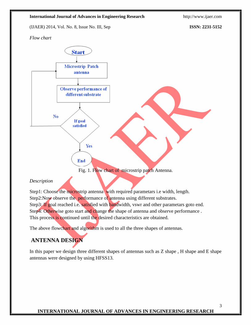
Flow chart
Fig. 1. Flow chart of microstrip patch Antenna.
Description
Step1: Choose the microstrip antenna with required parametars i.e width, length.
Step2:Now observe the performance of antenna using different substrates.
Step3: If goal reached i.e. satisfied with bandwidth, vswr and other parametars goto end.
Step4: Otherwise goto start and change the shape of antenna and observe performance .
This process is continued until the desired characteristics are obtained.
The above flowchart and algorithm is used to all the three shapes of antennas.
ANTENNA DESIGN
In this paper we design three different shapes of antennas such as Z shape , H shape and E shape
antennas were designed by using HFSS13.
International Journal of Advances in Engineering Research http://www.ijaer.com
(IJAER) 2014, Vol. No. 8, Issue No. III, Sep ISSN: 2231-5152
4
INTERNATIONAL JOURNAL OF ADVANCES IN ENGINEERING RESEARCH
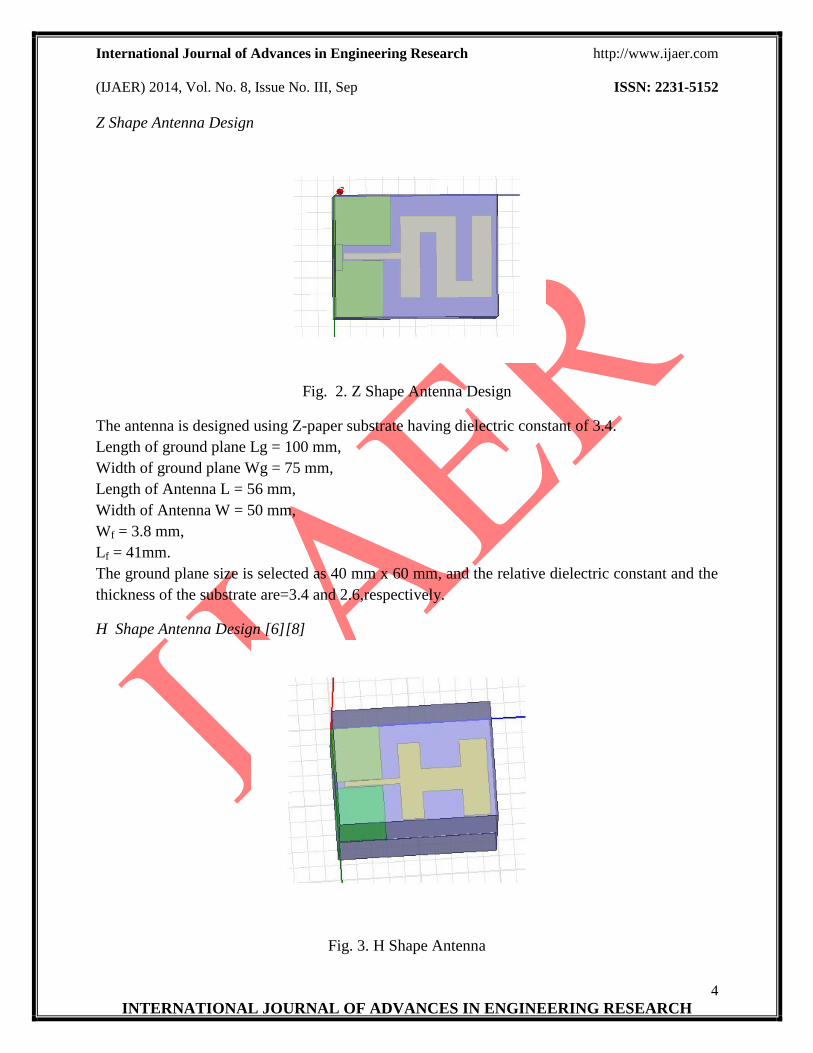
Z Shape Antenna Design
Fig. 2. Z Shape Antenna Design
The antenna is designed using Z-paper substrate having dielectric constant of 3.4.
Length of ground plane Lg = 100 mm,
Width of ground plane Wg = 75 mm,
Length of Antenna L = 56 mm,
Width of Antenna W = 50 mm,
Wf = 3.8 mm,
Lf = 41mm.
The ground plane size is selected as 40 mm x 60 mm, and the relative dielectric constant and the
thickness of the substrate are=3.4 and 2.6,respectively.
H Shape Antenna Design [6][8]
Fig. 3. H Shape Antenna

International Journal of Advances in Engineering Research http://www.ijaer.com
(IJAER) 2014, Vol. No. 8, Issue No. III, Sep ISSN: 2231-5152
5
INTERNATIONAL JOURNAL OF ADVANCES IN ENGINEERING RESEARCH
The physical parametars and flow chart of E shape antenna is similar to the Z shpe antenna.
The antenna is designed using FR4 glass epoxy substrate having dielectric constant of 4.4.
Length of ground plane Lg = 100 mm,
Width of ground plane Wg = 75 mm,
Length of Antenna L = 56 mm,
Width of Antenna W = 50 mm,
Wf = 3.8 mm,
Lf = 41mm.
The ground plane size is selected as 40 mm x 60 mm, and the relative dielectric constant and the
thickness of the substrate are=4.4and 2.2 respectively.
E Shape Antenna Design [1][5]
Fig. 4. E Shape Antenna
The physical parametars and flow chart of E shape antenna is similar to the Z shpe antenna.
The antenna is designed using FR 4 glass epoxy substrate having dielectric constant of 4.4.
Length of ground plane Lg = 100 mm,
Width of ground plane Wg = 75 mm,
Length of Antenna L = 56 mm,
Width of Antenna W = 50 mm,
Wf = 3.8 mm,
Lf = 41mm.
The ground plane size is selected as 40 mm x 60 mm, and the relative dielectric constant and the
thickness of the substrate are=4.4and 2.2 respectively.
International Journal of Advances in Engineering Research http://www.ijaer.com
(IJAER) 2014, Vol. No. 8, Issue No. III, Sep ISSN: 2231-5152
6
INTERNATIONAL JOURNAL OF ADVANCES IN ENGINEERING RESEARCH
SIMULATED RESULTS
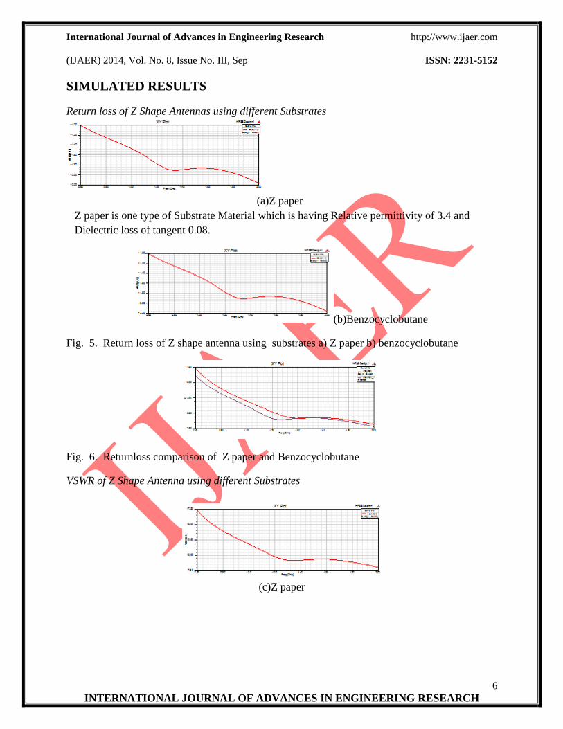
Return loss of Z Shape Antennas using different Substrates
(a)Z paper
Z paper is one type of Substrate Material which is having Relative permittivity of 3.4 and
Dielectric loss of tangent 0.08.
(b)Benzocyclobutane
Fig. 5. Return loss of Z shape antenna using substrates a) Z paper b) benzocyclobutane
Fig. 6. Returnloss comparison of Z paper and Benzocyclobutane
VSWR of Z Shape Antenna using different Substrates
(c)Z paper

International Journal of Advances in Engineering Research http://www.ijaer.com
(IJAER) 2014, Vol. No. 8, Issue No. III, Sep ISSN: 2231-5152
7
INTERNATIONAL JOURNAL OF ADVANCES IN ENGINEERING RESEARCH
(d)Benzocyclobutane
Fig. 7. VSWR of Z shape antenna using c)Zpaper,d)Benzocyclobutane:
Fig. 8. VSWR comparison of Z paper and Benzocyclobutane
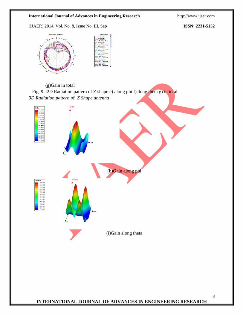
2D Radiation pattern of Z Shape antenna
(e)Gain along phi
(f)Gain along theta
International Journal of Advances in Engineering Research http://www.ijaer.com
(IJAER) 2014, Vol. No. 8, Issue No. III, Sep ISSN: 2231-5152
8
INTERNATIONAL JOURNAL OF ADVANCES IN ENGINEERING RESEARCH
(g)Gain in total
Fig. 9. 2D Radiation pattern of Z shape e) along phi f)along theta g) in total
3D Radiation pattern of Z Shape antenna
(h)Gain along phi
(i)Gain along theta
International Journal of Advances in Engineering Research http://www.ijaer.com
(IJAER) 2014, Vol. No. 8, Issue No. III, Sep ISSN: 2231-5152
9
INTERNATIONAL JOURNAL OF ADVANCES IN ENGINEERING RESEARCH
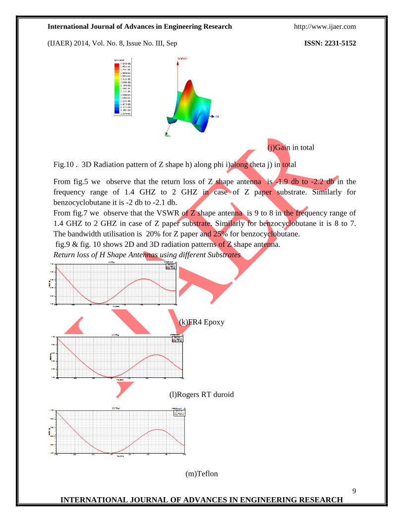
(j)Gain in total
Fig.10 . 3D Radiation pattern of Z shape h) along phi i)along theta j) in total
From fig.5 we observe that the return loss of Z shape antenna is -1.9 db to -2.2 db in the
frequency range of 1.4 GHZ to 2 GHZ in case of Z paper substrate. Similarly for
benzocyclobutane it is -2 db to -2.1 db.
From fig.7 we observe that the VSWR of Z shape antenna is 9 to 8 in the frequency range of
1.4 GHZ to 2 GHZ in case of Z paper substrate. Similarly for benzocyclobutane it is 8 to 7.
The bandwidth utilisation is 20% for Z paper and 25% for benzocyclobutane.
fig.9 & fig. 10 shows 2D and 3D radiation patterns of Z shape antenna.
Return loss of H Shape Antennas using different Substrates
(k)FR4 Epoxy
(l)Rogers RT duroid
(m)Teflon

International Journal of Advances in Engineering Research http://www.ijaer.com
(IJAER) 2014, Vol. No. 8, Issue No. III, Sep ISSN: 2231-5152
10
INTERNATIONAL JOURNAL OF ADVANCES IN ENGINEERING RESEARCH
Fig. 11 . Return loss of H shape antenna using substrates k) FR4
l) Rogers RT duroid m) Teflon
Fig. 12. Returnloss comparison of FR4,Rogers RT duroid and Teflon
VSWR of H Shape Antenna using different Substrates
(n)FR4 Epoxy
(o)RogersRTduroid
(p)Teflon
Fig. 13. VSWR of H shape antenna using substrates n) FR4 o) Rogers RT duroid p) Teflon
Fig. 14. VSWR comparison of H shape antenna using substrates n) FR4 o) Rogers RT duroid
p) Teflon
International Journal of Advances in Engineering Research http://www.ijaer.com
(IJAER) 2014, Vol. No. 8, Issue No. III, Sep ISSN: 2231-5152
11
INTERNATIONAL JOURNAL OF ADVANCES IN ENGINEERING RESEARCH
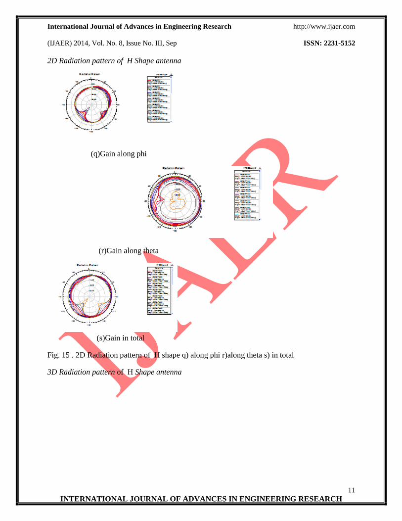
2D Radiation pattern of H Shape antenna
(q)Gain along phi
(r)Gain along theta
(s)Gain in total
Fig. 15 . 2D Radiation pattern of H shape q) along phi r)along theta s) in total
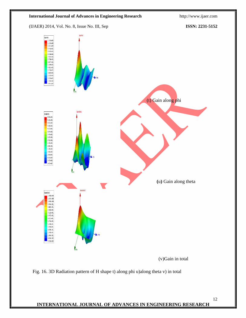
3D Radiation pattern of H Shape antenna
International Journal of Advances in Engineering Research http://www.ijaer.com
(IJAER) 2014, Vol. No. 8, Issue No. III, Sep ISSN: 2231-5152
12
INTERNATIONAL JOURNAL OF ADVANCES IN ENGINEERING RESEARCH
(t) Gain along phi
(u) Gain along theta
(v)Gain in total
Fig. 16. 3D Radiation pattern of H shape t) along phi u)along theta v) in total
International Journal of Advances in Engineering Research http://www.ijaer.com
(IJAER) 2014, Vol. No. 8, Issue No. III, Sep ISSN: 2231-5152
13
INTERNATIONAL JOURNAL OF ADVANCES IN ENGINEERING RESEARCH
From fig.11 we observe that the return loss of H shape antenna is -4 db to -2. db in the
frequency range of 1.2 GHZ to 1.7 GHZ for FR4 Epoxy substrate, for rogers RT duroid the
return loss is -4 db to -2.5 db.Similarly for teflon it was -4 db to -2.5 db.
From fig.14 we observe that the VSWR of H shape antenna is 4.5 to 7 in the frequency range
of 1.4 GHZ to 1.7 GHZ for FR4 Epoxy substrate. for rogers RT duroid the VSWR is 4.5 to 6.5.
Similarly for Teflon it is 4.25 to 6.75. The bandwidth utilisation is 35% for FR4 , 40% for
rogers RT duroid and 40% for Teflon material.
Fig.15 & fig. 16 shows 2D and 3D radiation patterns of H shape antenna.
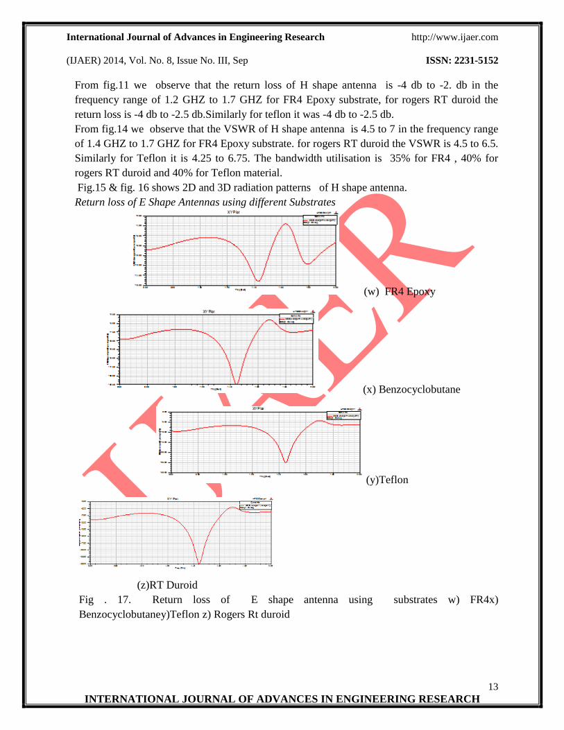
Return loss of E Shape Antennas using different Substrates
(w) FR4 Epoxy
(x) Benzocyclobutane
(y)Teflon
(z)RT Duroid
Fig . 17. Return loss of E shape antenna using substrates w) FR4x)
Benzocyclobutaney)Teflon z) Rogers Rt duroid
International Journal of Advances in Engineering Research http://www.ijaer.com
(IJAER) 2014, Vol. No. 8, Issue No. III, Sep ISSN: 2231-5152
14
INTERNATIONAL JOURNAL OF ADVANCES IN ENGINEERING RESEARCH
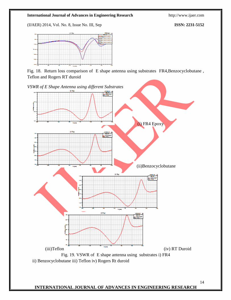
Fig. 18. Return loss comparison of E shape antenna using substrates FR4,Benzocyclobutane ,
Teflon and Rogers RT duroid
VSWR of E Shape Antenna using different Substrates
(i) FR4 Epoxy
(ii)Benzocyclobutane
(iii)Teflon (iv) RT Duroid
Fig. 19. VSWR of E shape antenna using substrates i) FR4
ii) Benzocyclobutane iii) Teflon iv) Rogers Rt duroid

International Journal of Advances in Engineering Research http://www.ijaer.com
(IJAER) 2014, Vol. No. 8, Issue No. III, Sep ISSN: 2231-5152
15
INTERNATIONAL JOURNAL OF ADVANCES IN ENGINEERING RESEARCH
Fig. 20. VSWR comparison of FR4,Rogers RT duroid and Teflon
2D Radiation pattern of E Shape antenna
-32.00
-24.00
-16.00
-8.00
90
60
30
0
-30
-60
-90
-120
-150
-180
150
120
HFSSDesign1Radiation Pattern 50 ANSOFT
Curve Info
dB(GainPhi)Setup1 : LastAdaptiveFreq='1.6GHz' Theta='0deg'
dB(GainPhi)Setup1 : LastAdaptiveFreq='1.6GHz' Theta='10deg'
dB(GainPhi)Setup1 : LastAdaptiveFreq='1.6GHz' Theta='20deg'
dB(GainPhi)Setup1 : LastAdaptiveFreq='1.6GHz' Theta='30deg'
dB(GainPhi)Setup1 : LastAdaptiveFreq='1.6GHz' Theta='40deg'
dB(GainPhi)Setup1 : LastAdaptiveFreq='1.6GHz' Theta='50deg'
dB(GainPhi)Setup1 : LastAdaptiveFreq='1.6GHz' Theta='60deg'
(v)Gain along phi
-64.00
-48.00
-32.00
-16.00
90
60
30
0
-30
-60
-90
-120
-150
-180
150
120
HFSSDesign1Radiation Pattern 51 ANSOFT
Curve Info
dB(GainTheta)Setup1 : LastAdaptiveFreq='1.6GHz' Theta='0deg'
dB(GainTheta)Setup1 : LastAdaptiveFreq='1.6GHz' Theta='10deg'
dB(GainTheta)Setup1 : LastAdaptiveFreq='1.6GHz' Theta='20deg'
dB(GainTheta)Setup1 : LastAdaptiveFreq='1.6GHz' Theta='30deg'
dB(GainTheta)Setup1 : LastAdaptiveFreq='1.6GHz' Theta='40deg'
dB(GainTheta)Setup1 : LastAdaptiveFreq='1.6GHz' Theta='50deg'
dB(GainTheta)Setup1 : LastAdaptiveFreq='1.6GHz' Theta='60deg'
(vi)Gain along theta
-20.00
-15.00
-10.00
-5.00
90
60
30
0
-30
-60
-90
-120
-150
-180
150
120
HFSSDesign1Radiation Pattern 49 ANSOFT
Curve Info
dB(GainTotal)Setup1 : LastAdaptiveFreq='1.6GHz' Theta='0deg'
dB(GainTotal)Setup1 : LastAdaptiveFreq='1.6GHz' Theta='10deg'
dB(GainTotal)Setup1 : LastAdaptiveFreq='1.6GHz' Theta='20deg'
dB(GainTotal)Setup1 : LastAdaptiveFreq='1.6GHz' Theta='30deg'
dB(GainTotal)Setup1 : LastAdaptiveFreq='1.6GHz' Theta='40deg'
dB(GainTotal)Setup1 : LastAdaptiveFreq='1.6GHz' Theta='50deg'
dB(GainTotal)Setup1 : LastAdaptiveFreq='1.6GHz' Theta='60deg'
International Journal of Advances in Engineering Research http://www.ijaer.com
(IJAER) 2014, Vol. No. 8, Issue No. III, Sep ISSN: 2231-5152
16
INTERNATIONAL JOURNAL OF ADVANCES IN ENGINEERING RESEARCH
(vii)Gain in total
Fig. 21. 2D Radiation pattern of E shape v) along phi vi)along theta vii) in total
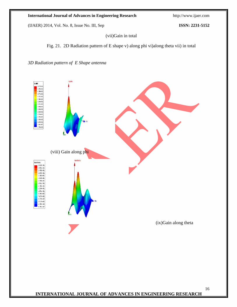
3D Radiation pattern of E Shape antenna
(viii) Gain along phi
(ix)Gain along theta
International Journal of Advances in Engineering Research http://www.ijaer.com
(IJAER) 2014, Vol. No. 8, Issue No. III, Sep ISSN: 2231-5152
17
INTERNATIONAL JOURNAL OF ADVANCES IN ENGINEERING RESEARCH
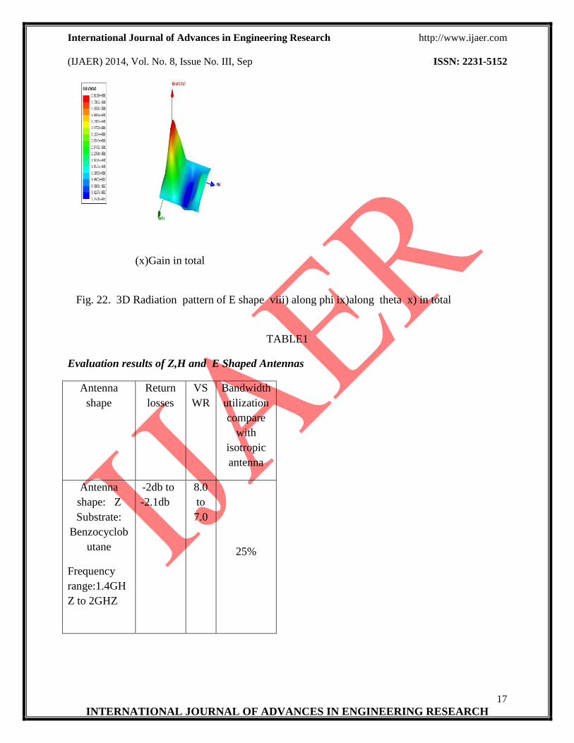
(x)Gain in total
Fig. 22. 3D Radiation pattern of E shape viii) along phi ix)along theta x) in total
TABLE1
Evaluation results of Z,H and E Shaped Antennas
Antenna
shape
Return
losses
VS
WR
Bandwidth
utilization
compare
with
isotropic
antenna
Antenna
shape: Z
Substrate:
Benzocyclob
utane
Frequency
range:1.4GH
Z to 2GHZ
-2db to
-2.1db
8.0
to
7.0
25%
International Journal of Advances in Engineering Research http://www.ijaer.com
(IJAER) 2014, Vol. No. 8, Issue No. III, Sep ISSN: 2231-5152
18
INTERNATIONAL JOURNAL OF ADVANCES IN ENGINEERING RESEARCH
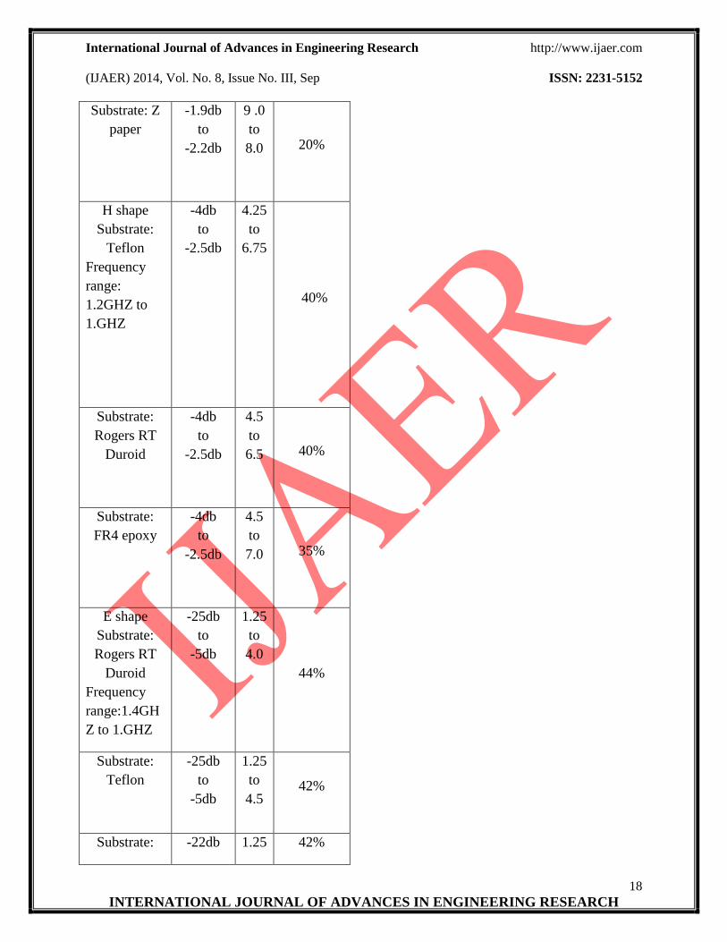
Substrate: Z
paper
-1.9db
to
-2.2db
9 .0
to
8.0 20%
H shape
Substrate:
Teflon
Frequency
range:
1.2GHZ to
1.GHZ
-4db
to
-2.5db
4.25
to
6.75
40%
Substrate:
Rogers RT
Duroid
-4db
to
-2.5db
4.5
to
6.5 40%
Substrate:
FR4 epoxy
-4db
to
-2.5db
4.5
to
7.0 35%
E shape
Substrate:
Rogers RT
Duroid
Frequency
range:1.4GH
Z to 1.GHZ
-25db
to
-5db
1.25
to
4.0
44%
Substrate:
Teflon
-25db
to
-5db
1.25
to
4.5 42%
Substrate: -22db 1.25 42%
International Journal of Advances in Engineering Research http://www.ijaer.com
(IJAER) 2014, Vol. No. 8, Issue No. III, Sep ISSN: 2231-5152
19
INTERNATIONAL JOURNAL OF ADVANCES IN ENGINEERING RESEARCH
Benzocyclob
utane
to
-5db
to
4.5
Substrate:
FR4
-15db to
-3db
1.5
to
4.5
40%
CONCLUSION
The simulated results show the performance of Z shape, H shape, E shape Microstrip patch
antennas. Band width, VSWR, Return loss for these antennas have been caliculated. The results
show that E shape antenna has better performance in the range of frequencies (0.6GHz-2GHz),
since the VSWR of E shape antenna is 1.25 at 1.4 GHz and the Bandwidth utilisation is 44%
when compared with the reference antenna and return loss is -25db. Thus E shaped antenna is
found to give much better than Z shape and H shape antennas.
REFERENCES
[1]A.khidre,K.FonfLee,Fanyang, ”Wideband Circularly Polarized E-Shape Patch Antenna for
Wireless Applications ”IEEE trans. Antenna propagation ,vol.52,no.5 pp 219-227.
[2] Ashishkumar “Rectangular Microstrip patch antenna using ’L’ Slot Structure” ISTP Trans
vol2, issue 2, march 2013, pp 15-18.
[3] Alak Majumder “Rectangular Microstrip patch Antenna using Coaxial probe Feeding
Technique to operate in S-Band” IJETT,vol4issue4,april2013,pp 1206-1210.
[4]Y.Sung “A printed Wide-slot Antenna With a Modified L- shaped Microstrip Line for
Wideband Applications”IEEE trans on Antenna and Propagation,vol.59,no.10,pp 3918-3922.
[5]Nisha gaur, Devendra Soni “E-Shaped Slotted Microstrip Antenna with Enhanced Gain for
Wireless Communication”,IJECSE,VIN2-436-441
[6]Xian-Ling Liang and tayeb A.Denidni, ”H-shaped Dielectric Resonator Antenna for
Wideband Applications” IEEE trans Antenna propagation , vol.7,2008. Pp 163-166
[7]B.sai Sandeep “Design and simulation of Microstrip Array Antenna for Wireless
Communications at 2.4 GHz” IJSER, vol3,issue11,nov-2012, pp 1-5
[8]Alak Majumder “Design of an H-Shaped Microstrip Patch Antenna for Applications” IJIAS,
vol3, no4pp , 987-994.

International Journal of Advances in Engineering Research http://www.ijaer.com
(IJAER) 2014, Vol. No. 8, Issue No. III, Sep ISSN: 2231-5152
20
INTERNATIONAL JOURNAL OF ADVANCES IN ENGINEERING RESEARCH
[9]WWW.AnsoftHFSS.com.
[10]C.A.Balanis, Antenna Theory: Analysis and Design, second edition, New York ,
JohnWiley&son’s,INC 1999.
[11]D. M. Pozar, “Microstrip antenna coupled to a Microstrip-line,” Electron. Lett., vol. 21, no.
2, pp. 49–50, Jan. 1985.


![Performance Optimization of a Microstrip Patch Antenna ... · COAXIAL PROBE FED RECTANGULAR MICROSTRIP PATCH ANTENNA [1] R. Garg, P. Bhartia, I. Bahl, and A. Ittipibon, Microstrip](https://img.pdfslide.net/doc/110x75/6038ae9acc6dac1a041c5fcd/performance-optimization-of-a-microstrip-patch-antenna-coaxial-probe-fed-rectangular.jpg)