Embed Size (px)
Citation preview

Svensk Kärnbränslehantering ABSwedish Nuclear Fueland Waste Management Co
Box 250, SE-101 24 Stockholm Phone +46 8 459 84 00
Technical Report
TR-10-12
Design and production of the KBS-3 repository
Svensk Kärnbränslehantering AB
December 2010
CM
Gru
ppen
AB
, Bro
mm
a, 2
010

Tänd ett lager: P, R eller TR.
Design and production of the KBS‑3 repository
Svensk Kärnbränslehantering AB
December 2010
ISSN 1404-0344
SKB TR-10-12
ID 1168741
Updated 2013-10
Keywords: Final repository, KBS-3 repository, Spent nuclear fuel, Safety report, Design premise, Treaty, Law, Regulation, KBS-3 system, Production, Production line, Quality management, Safety classification.
A pdf version of this document can be downloaded from www.skb.se.

Update notice
The original report, dated December 2010, was found to contain factual errors which have been corrected in this updated version. The corrected factual errors are presented below.
Updated 2013-10
Location Original text Corrected text
Page 60, reference SKI 2006 SKI Rapport 2006:109 SKI-Utredningsrapport 2006/109

TR-10-12 3
Preface
An important part of SKB’s licence application for the construction, possession and operation of the KBS‑3 repository is the safety report. The safety report addresses both safety during operation of the KBS‑3 repository facility (SR‑Operation), and the long‑term safety of the KBS‑3 repository (SR‑Site).
For the construction of the KBS‑3 repository SKB has defined a set of production lines:
• thespentnuclearfuel,
• thecanister,
• thebuffer,
• thebackfill,
• theclosure,and
• theundergroundopenings.
These production lines are reported in separate Production reports, and in addition there is a Repository production report presenting the common basis for the reports.
This set of reports addresses design premises, reference design, conformity of the reference design to design premises, production and the initial state, i.e. the results of the production. Thus the reports provide input to SR‑Site concerning the characteristics of the as built KBS‑3 repository and to SR‑Operation concerning the handling of the engineered barriers and construction of underground openings.
The preparation of the set of reports has been lead and coordinated by Lena Morén with support from Roland Johansson, Karin Pers and Marie Wiborgh.
This report has been authored by Lena Morén.

TR-10-12 5
Summary
The report contains the common basis for a set of Production reports, presenting how the KBS‑3 repository is designed, produced and inspected. The set of reports is included in the safety report for the KBS‑3 repository and repository facility.
The report presents the role of the Production reports within the safety report and their common purposesandobjectives.Animportantpartofthereportistopresentthebackgroundandsourcesto the principles to be applied in the design, the functions of the KBS‑3 repository and the barrier functionstheengineeredbarriersandrock.Further,themethodologytosubstantiatedetaileddesignpremises for the engineered barriers, underground openings and other parts of the KBS‑3 repository is presented. The report also gives an overview of the KBS‑3 system and its facilities and the pro‑duction lines for the spent fuel, the engineered barriers and underground openings. Finally, an introduction to quality management, safety classification and their application is given.
Substantiation of design premisesBased on international treaties, national laws and regulations SKB has substantiated functions and design considerations as a specification of the KBS‑3 repository, and as guidelines for the design of its engineered barriers and underground openings. The properties of the spent nuclear fuel are another important basis for the design of the KBS‑3 repository.
The safety and radiation principles of most importance for the design of the KBS‑3 repository are the multi barrier principle, the defence‑in‑depth principle and.radiation protection principles to protect both human health and the environment and both current and future generations. The time required for the radiotoxicity of the spent nuclear fuel to decay to naturally occurring levels is also important for the design.
ThefunctionsoftheKBS-3repositoryaremaintainedbyitsengineeredbarriersandtherock.The barrier functions of the engineered barriers and the functions of the underground openings, to utilisetherockasabarrier,aresubstantiatedfromthefunctionsoftheKBS-3repositorytocontainthe spent fuel and retard the dispersion of radioactive substances. The properties of the engineered barriers and underground openings, e.g. their geometry and strength, shall sustain the functions. The substantiation of detailed design premises for these properties is an iterative process requiring input andfeedbackfromtechnicaldevelopmentandsafetyassessments.
The design premises related to the functions in the KBS‑3 repository are based on the results from the assessment of the long‑term safety and the identification of a number of design basis cases. To be technicallyfeasiblethedifferentpartsoftherepositorymustfit,andwork,together,andthedesignof one component may constitute a design premise for another. The properties of importance for the function in the KBS‑3 repository shall be possible to achieve and inspect and the production methods may provide design premises. With respect to the operational safety the canister shall remain tight for all conceivable occurring loads. To minimise the radiation doses to the personnel it is desirable that the canisters are always fit for deposition and that retrieval of deposited canisters is avoided, this implies that loads occurring during handling and operation also provide premises for the design.
The KBS‑3 repositoryIn the KBS‑3 repository the spent nuclear fuel has been encapsulated in tight, corrosion resistant andloadbearingcanisters;thecanistershavebeendepositedincrystallinerockatadepthof400–700 metres; the canisters have been surrounded by a buffer which prevents the flow of water and protects them and thecavitiesintherockthatarerequiredforthedepositionofcanistershavebeenbackfilledandclosed.
All spent nuclear fuel from the Swedish nuclear power programme shall be encapsulated, deposited and finally stored in the KBS‑3 repository. After closure, the KBS‑3 repository shall contain the spent nuclear fuel and isolate it from man and the environment. If the containment is breached, the

6 TR-10-12
final repository shall prevent or retard the dispersion of radioactive substances so that the ionising radiation, if some of the radioactive substances finally reach the environment at the surface, does not cause harm.
AKBS-3repositorycomprisestherockattherepositorysite,thecanisterscontainingspentnuclearfuel,buffer,backfillandclosuresaswellasengineeredandresidualmaterialsthatremainintherockoncetheundergroundopeningshavebeenbackfilledandclosed.
The KBS‑3 system and the production linesThe KBS‑3 system refers to the nuclear facilities etc that are required to realise the final deposition of spent nuclear fuel according to the KBS‑3 method. The KBS‑3 system consists of a central facility forintermediatestorageandencapsulationofspentnuclearfuel(Clink),asystemfortransportationof canisters with spent nuclear fuel and a final repository facility.
ThepurposeofClinkistostorethespentnuclearfueluntilitsdecaypowerhasdecreasedtolevelssuitable for deposition and to select assemblies for encapsulation, encapsulate them and deliver sealed canisters. The purpose of the transport system is to transport encapsulated spent fuel from Clinktothefinalrepositoryfacilityanddelivercanistersfitfordeposition.Thefinalrepositoryfacility is the facility required to construct the KBS‑3 repository.
The production lines refer to all the activities and stages required to handle the spent fuel and to produce and inspect the engineered barriers and install them in the KBS‑3 repository. The production also comprises the specification of the components to be delivered and the methods for manufactur‑ing and inspection. For the underground openings the methods to successively adapt the design to the conditions at the site and to construct the different underground openings as well as their capability to result in underground openings that conform to the design premises are presented.
As mentioned there are design premises related to technical feasibility, i.e. that the different parts oftherepositorymustfitandworktogetherduringtheproductionoftheKBS-3repository.Someof these design premises are the result of interfaces between the spent fuel line, the production lines of the engineered barriers, the production of the plugs and the construction of the underground open‑ings. An overview of the interfaces and the resulting design premises are given in the report.
Quality management, safety classification and their applicationWithin the Production reports quality refers to the degree to which the characteristics of the finished parts of the KBS‑3 repository contribute towards sustaining the functions of importance for the long‑term safety. Quality management refers to activities to direct and control an organisation with regard to quality. Quality control and quality assurance are parts of the quality management relevant for the Production reports. The quality control is focused on fulfilling the quality requirements while the quality assurance is focused on providing confidence that quality requirements will be fulfilled. For the production of the KBS‑3 repository quality control and quality assurance imply that procedure documents to be applied when carrying out the activities that impact, and provide confidence in, the quality of the finished KBS‑3 repository shall be available within the quality management system.
To adapt the different parts in the KBS‑3 repository to their importance for the safety SKB intends to apply a classification system. The different parts of the KBS‑3 repository are classified with respect to their importance for the functions of the KBS‑3 repository to contain, prevent or retard the disper‑sion of radioactive substances. The safety classes are denominated B – Barrier function and PB – Impact on barrier function respectively. The extent of quality assurance measures is determined by the safety classification. This implies that more extensive quality assurance measures are required for parts with safety class B than for parts with safety class PB. SKB intends to establish quality plans for the engineered barriers, underground openings and other parts of the KBS‑3 repository. The quality plans shall specify which procedures and associated resources that shall be applied by whom and when for the activities that impact the quality.
TR-10-12 7
Sammanfattning
RapportenomfattardegemensammautgångspunkternaförengruppProduktionsrapporter som redovisarhurKBS-3-förvaretärutformat,produceratochkontrollerat.GruppenavrapporteringårisäkerhetsredovisningenförKBS-3-förvaretochförvarsanläggningen.
RapportenredovisarProduktionsrapporternasrollisäkerhetsredovisningenochderasgemensammasyftenochmål.Enviktigdelavrapportenärattredovisabakgrundochkällortillprincipernasomskatillämpasvidutformningen,KBS-3-förvaretsfunktioner,detekniskabarriärernasochbergetsbarriärfunktioner.Vidareredovisasmetodikenförattunderbyggadetaljeradekonstruktionsförutsätt-ningarfördetekniskabarriärerna,bergutrymmenaochandradelarnaiKBS-3-förvaret.RapportengerocksåenöverblicköverKBS-3-systemetochdessanläggningarochproduktionslinjernafördetanvändakärnbränslet,detekniskabarriärernaochbergutrymmena.Slutligen,gesenintroduktiontillkvalitetsledning,säkerhetsklassningochderastillämpning.
Underbyggande av konstruktionsförutsättningarBaseratpåinternationellaavtal,nationellalagarochföreskrifterharSKBunderbyggtfunktionerochdesignövervägandensomenspecifikationavKBS-3-förvaretochsomriktlinjerförutformningenavdesstekniskabarriärerochbergutrymmen.DetanvändakärnbränsletsegenskaperärenannanviktigutgångspunktförutformningenavKBS-3-förvaret.
DesäkerhetsochstrålskyddsprincipersomharstörstbetydelseförutformningenavKBS-3-förvaretärflerbarriärsprincipen,djupförsvarsprincipenochstrålskyddsprincipernaattskyddabådemän‑niskorshälsaochmiljönochbådenuvarandeochkommandegenerationer.Tidendettarfördetanvändakärnbränsletsradiotoxicitetattavklingatillnaturligtförekommandenivåerärocksåviktigförutformningen.
KBS-3-förvaretsfunktionerupprätthållsavdesstekniskabarriärerochavberget.DetekniskabarriärernasbarriärfunktionerochbergutrymmenasfunktionerattutnyttjabergetsombarriärärunderbyggdaavKBS-förvaretsfunktionerattinneslutadetanvändakärnbränsletochfördröjaradionuklidtransport.Egenskapernahosdetekniskabarriärernaochhosbergutrymmena,texderasgeometriochhållfasthet,skaupprätthållafunktionerna.Attunderbyggadetaljeradekonstruktions‑förutsättningarfördessaegenskaperäreniterativprocesssomkräverinputochåterkopplingfråntekniskutvecklingochsäkerhetsanalyser.
KonstruktionsförutsättningarrelateradetillfunktioneriKBS-3-förvaretärbaseradepåresultatfrånanalysenavdenlångsiktigasäkerhetenochidentifieringenavenuppsättningkonstruktionsstyrandefall.Förattvarateknisktgenomförbaramåstedeolikadelarnaavförvaretpassaihopochfungeratillsammans,ochendelkanutgöraenkonstruktionsförutsättningförenannan.EgenskapernamedbetydelseförfunktioneniKBS-3-förvaretmåstevaramöjligaattåstadkommaochkontrolleraochproduktionsmetodernakangekonstruktionsförutsättningar.Medhänsyntilldriftsäkerhetskakapselnförblitätförallatänkbaraförkommandelaster.Förattminimerastrålningsdosertillpersonalärdetönskvärtattkapslarnaalltidärtillåtnafördeponeringochattåtertagavdeponeradekapslarundviks,detmedförattlastersomförekommerunderhanteringochdriftocksågerkonstruktionsförutsätt‑ningar.
KBS‑3‑förvaretIettKBS-3-förvarhardetanvändakärnbränsletkapslatsinitäta,lastbärandekapslarsomärmot-ståndskraftigamotkorrosion,kapslarnahardeponeratsikristallintbergpå400–700metersdjupochomgettsavenbuffertsomförhindrarvattenflödeochskyddardem,ochdeutrymmenibergetsomkrävsfördeponeringharåterfylltsochförslutits.
Alltanväntkärnbränslefråndetsvenskakärnkraftsprogrammetskakapslasin,deponerasochslut‑förvarasiKBS-3-förvaret.EfterförslutningskaKBS-3-förvaretinneslutadetanvändakärnbränsletochisoleradetfrånmänniskanochmiljön.Ominneslutningenbrytsskaslutförvaretförhindraoch

8 TR-10-12
fördröjautsläppavradioaktivaämnensåattdenjoniserandestrålningen,omämnenaslutligennårmiljönpåmarkytan,inteorsakarskada.
EttKBS-3-förvaromfattarbergetpåförvarsplatsen,kapslarnamedanväntkärnbränsle,buffert,återfyllningochförslutningarsamtdekonstruktionerochfrämmandematerialsomfinnskvaribergetdåbergutrymmenaåterfylltsochförslutits.
KBS‑3‑systemet och produktionslinjernaKBS-3-systemetavserdekärntekniskaanläggningarmmsombehövsförattgenomföraslutförvaringavanväntkärnbränsleenligtKBS-3-metoden.KBS-3-systemetbeståravencentralanläggningförmellanlagringochinkapslingavdetanvändakärnbränslet(Clink),etttransportsystemförtransporteravkapslarmedanväntkärnbränsleochenslutförvarsanläggning.
Clinkssyfteärattlagradetanvändakärnbränslettillsresteffektenharavklingattillnivåerlämpligafördeponeringochattväljaelementförinkapsling,kapslaindemochlevereraförslutnakapslar.TransportsystemetssyfteäratttransporterainkapslatanväntkärnbränslefrånClinktillslutförvars-anläggningenochlevererakapslartillåtnafördeponering.Slutförvarsanläggningenärdenanlägg‑ningsomkrävsförattbyggaKBS-3-förvaret.
Produktionslinjernaavserallaaktiviteterochmomentsomkrävsföratthanteradetanvändakärn‑bränsletochproduceraochkontrolleradetekniskabarriärernasamtinstallerademiKBS-3-förvaret.Produktionenomfattarävenspecifikationavkomponentersomskalevererasochmetodernaförtillverkningochkontroll.Förbergutrymmenabeskrivsmetodernaattsuccessivtanpassautform‑ningentillförhållandenapåplatsenochförattbyggadeolikabergutrymmena,samtderasförmågaattåstadkommabergutrymmensomöverensstämmermedkonstruktionsförutsättningarna.
Somnämntsfinnskonstruktionsförutsättningarrelateradetilltekniskgenomförbarhet,dvsattdeolikadelarnaavförvaretmåstepassaihopochfungeratillsammansunderproduktionenavKBS-3-förvaret.Någraavdessakonstruktionsförutsättningarärresultatetavgränssnittenmellanbränslelinjen,produktionslinjernafördetekniskabarriärerna,produktionenavpluggarochutbyggnadenbergutrymmen.Irapportengesenöverblickövergränssnittenochderesulterandekonstruktionsförutsättningarna.
Kvalitetsledning, säkerhetsklassning och deras tillämpningInomProduktionsrapporternaavserkvalitetdengradtillvilkenegenskapernahosdefärdigställdadelarnaavKBS-3-förvaretbidrartillattupprätthållafunktionernamedbetydelsefördenlångsiktigasäkerheten.Kvalitetsledningavseraktiviteterförattledaochstyraenorganisationmedavseendepåkvalitet.KvalitetsstyrningochkvalitetssäkringärdelaravkvalitetsledningensomärrelevantaförProduktionsrapporterna.Kvalitetsstyrningenärinriktadmotattuppfylla kvalitetskravochkvalitetssäkringenärinriktadmotattgetilltrotillattkvalitetskravuppfylls.FörproduktionenavKBS-3-förvaretinnebärkvalitetsstyrningochkvalitetssäkringattrutinersomskatillämpasnäraktiviteternasompåverkar,ochgertilltrotill,kvalitetenhosdetfärdigbyggdaKBS-3-förvaretskafinnasikvalitetsledningssystemet.
FörattanpassadeolikadelarnaiKBS-3-förvarettillderasbetydelseförsäkerhetenavserSKBtill‑lämpaettklassningssystem.DeolikadelarnaiKBS-3-förvaretärklassademedhänsyntillsinbety‑delseförKBS-3-förvaretsfunktionerattinnesluta,förhindraochfördröjaspridningenavradioaktivaämnen.SäkerhetsklassernabenämnsB – barriärfunktionrespektivePB – påverkar barriärfunktion. Omfattningenavkvalitetssäkringsåtgärdernabestämsavsäkerhetsklassningen.DetinnebärattmeromfattandekvalitetssäkringsåtgärderkrävsfördelarmedsäkerhetsklassBänfördelarmedsäker‑hetsklassPB.SKBavserattupprättakvalitetsplanerfördetekniskabarriärerna,bergutrymmenaochandradelarnaiKBS-3-förvaret.Kvalitetsplanernaskaspecificeravilkarutinerochtillhöranderesursersomskallanvändasavvemochnärföraktiviteternasompåverkarkvaliteten.

TR-10-12 9
Contents
1 Introduction 111.1 Generalbasis 111.2 The role of this report within the safety report 121.3 Purpose, objectives and limitations 14
1.3.1 Purpose and objectives 141.3.2 Limitations 15
1.4 Structure and content 151.4.1 This report 151.4.2 The spent fuel report 161.4.3 The engineered barrier production reports 161.4.4 The underground openings construction report 16
1.5 Central concepts 17
2 Substantiation of design premises 192.1 Introduction 192.2 Lawsandregulationsandstakeholderdemands 202.3 The spent nuclear fuel to be deposited 222.4 Functions of the KBS‑3 repository and design considerations 23
2.4.1 Functions of the KBS‑3 repository 232.4.2 Designconsiderations 23
2.5 Designpremisesfromsafetyassessment,designandtechnology development 232.5.1 Generalapproach 232.5.2 DesignpremisesrelatedtothefunctionsintheKBS-3repository 252.5.3 DesignpremisesfromotherpartsoftheKBS-3repository 252.5.4 Designpremisesrelatedtoproductionandoperation 262.5.5 Designpremisesrelatedtothesafeoperationoftherepository
facility 27
3 The KBS‑3 repository 293.1 The KBS‑3 repository and its functions 29
3.1.1 Definitions,purposeandbasicdesign 293.1.2 The functions and properties of the KBS‑3 repository 303.1.3 The engineered barriers and other parts of the KBS‑3 repository 31
3.2 The spent nuclear fuel 323.2.1 Definition 323.2.2 Properties of importance for the design and long‑term safety of the
KBS‑3 repository 323.2.3 Kinds of spent fuel to be deposited 33
3.3 The canister 333.3.1 Definitionandpurpose 333.3.2 The barrier functions of the canister 333.3.3 Basic design of the canister 34
3.4 The buffer 343.4.1 Definitionandpurpose 343.4.2 The barrier functions of the buffer 343.4.3 Basic design of the buffer 35
3.5 Thebackfill 353.5.1 Definitionandpurpose 353.5.2 Thebarrierfunctionsofthebackfill 353.5.3 Basicdesignofthebackfill 35
3.6 The closure 353.6.1 Definitionandpurpose 353.6.2 The barrier functions of the closure 363.6.3 Basic design of the closure 36

10 TR-10-12
3.7 The underground openings 363.7.1 Definitionandpurpose 363.7.2 The functions of the underground openings 37
3.8 The plugs 383.8.1 Differentkindsofplugsandtheirpurpose 383.8.2 The function of the plugs 383.8.3 Basic design of the plugs 38
3.9 Designconsiderations 38
4 The KBS‑3 system and the production lines 414.1 The KBS‑3 system 41
4.1.1 Definitionandscope 414.1.2 Theinterimstorageandencapsulationplant–Clink 414.1.3 The transport system for canisters with encapsulated spent nuclear
fuel 424.1.4 The KBS‑3 repository facility 43
4.2 The production and the production lines 454.2.1 The production 454.2.2 The production lines 454.2.3 Designandproductionlineinterfaces 46
4.3 The spent fuel line 464.3.1 Overview 464.3.2 Interfaces between the design of the KBS‑3 repositry and its barriers
and the handling of the spent fuel 464.3.3 Production line interfaces 46
4.4 The canister production line 474.4.1 Overview 474.4.2 Designinterfaces 474.4.3 Production line interfaces 47
4.5 The buffer production line 474.5.1 Overview 474.5.2 Designinterfaces 474.5.3 Production line interfaces 47
4.6 Thebackfillproductionline 484.6.1 Overview 484.6.2 Designinterfaces 484.6.3 Production line interfaces 48
4.7 The closure production line 494.7.1 Overview 494.7.2 Designinterfaces 494.7.3 Production line interfaces 49
4.8 The production of plugs 494.8.1 Overview 494.8.2 Designinterfaces 494.8.3 Production line interfaces 49
4.9 The construction of the underground openings 494.9.1 Overview 494.9.2 Designinterfaces 504.9.3 Production line interfaces 51
5 Quality management, safety classification and thier application 535.1 Quality management 535.2 Safety classification 545.3 Application in the production of the KBS‑3 repository 55
5.3.1 Generalbasis 555.3.2 Quality plans and their scope 56
6 References 59

TR-10-12 11
1 Introduction
1.1 General basisThis report contains the common basis for a set of reports, referred to as the Production reports, presenting how the final repository for spent nuclear fuel is designed and constructed. It is part of the safety report for the final repository and repository facility for spent nuclear fuel.
The final repository is based on the KBS‑3 method developed by SKB. The term “KBS‑3 repository” refers to the final repository and the term “KBS‑3 repository facility” refers to the facility within which the KBS‑3 repository1isconstructed.DuringtheoperationalphasestheKBS-3repositoryfacilitywillcontainareaswherecanistersarebeingdepositedandbufferandbackfillinstalledaswellasareaswhereconstruction of new deposition tunnels and holes are underway, it will also contain finished parts of the KBS‑3 repository where deposition has been completed. When all canisters with spent fuel have been deposited, the KBS‑3 repository facility will be decommissioned and the KBS‑3 repository closed, see Figure 1‑1.
1 The terms “KBS‑3 repository” and “final repository” are used synonymously as are the terms “KBS‑3 reposi‑tory facility” and “final repository facility”.
Figure 1‑1. The KBS‑3 repository facility and the KBS‑3 repository. The KBS‑3 repository is constructed within the KBS‑3 repository facility.
Technical systems
Activities
Backfill
Backfill
Closure
Buffer
Canister with spentnuclear fuel
Canister with spent nuclear fuel
Plug
Underground openings
Underground openings
Host rock
Sub-surface facility
Surface facility
Buffer
Plug
Borehole closure
The KBS-3 repository facility with completed parts of the KBS-3 repository
The KBS-3 repository
Host rock

12 TR-10-12
The establishment of a KBS‑3 repository requires that there is a system, the KBS‑3 system, comprising the facilities, etc that are needed for the final disposal of spent nuclear fuel according to the KBS‑3 method. The KBS‑3 system consists of a central facility for interim storage and encapsulation of the spent nuclear fuel, a transport system for the transportation of canisters with encapsulated spent nuclear fuel and a final repository facility.
The KBS‑3 repository and its engineered barriers and underground openings are produced within the KBS‑3 system. SKB has defined the following production lines for the construction of the KBS‑3 repository:
• thespentnuclearfuel,
• thecanister,
• thebuffer,
• thebackfillindepositiontunnels,
• theclosure,
• theundergroundopenings.
The production lines comprise the deliveries to the KBS‑3 system, and the activities to handle the spent nuclear fuel, to produce and install the engineered barriers and to design and construct the underground openings.
1.2 The role of this report within the safety reportThe safety report to be submitted by SKB for approvals to construct, possess and operate the KBS‑3 repository facility comprises two main parts:
• thesafetyofthefacilityduringconstructionandoperation,SR‑Operation,
• thelong-termsafetyoftherepository,SR‑Site.
The structure of the safety report is illustrated in Figure 1‑2.
Both SR‑Site and SR‑Operation refer to the Production reports presenting how the KBS‑3 reposi‑tory is designed and constructed. The individual reports that form the set of Production reports and their short names used as references within the set of Production reports are illustrated in Figure 1‑3, their full names are given in Table 1‑1.
Figure 1‑2. The structure of the safety report. Grey parts belong to the safety report for the safety of the facility during construction and operation, blue parts belong to the safety report for the long‑term safety and white parts are common for the two parts.
Additional referencesTo the main report or main
references
SR-OperationSafety report for the operational
safety of the final repository facility(general part)
SR-SiteSafety report for the long-termsafety of the KBS-3 repository
(main report)
Main references to SR-siteProduction reportsSystem
descriptions(system part)
References tothe general part
Additional referencesTo the references to the general
part or system part
Additional referencesCommon for references to the general part or
system part and main references
Additional referencesTo the main report or main
references
SRSafety reportCommon part

TR-10-12 13
The Production reports provide the information on the handling of the spent nuclear fuel and the design and production of the engineered barriers and underground openings required to assess the long‑term safety of the KBS‑3 repository. The properties of the engineered barriers and underground openingsaredeterminedintheproductionandmustbeknowntoassessthelong-termsafety.
The Production reports provide information on the spent nuclear fuel to be deposited in the KBS‑3 repository, how to produce and inspect the engineered barriers and underground openings and how to handle the spent fuel and engineered barriers within the facilities of the KBS‑3 system. Further, they provide information on acceptable impairments on the engineered barriers in order for them to be fit for deposition or installation.
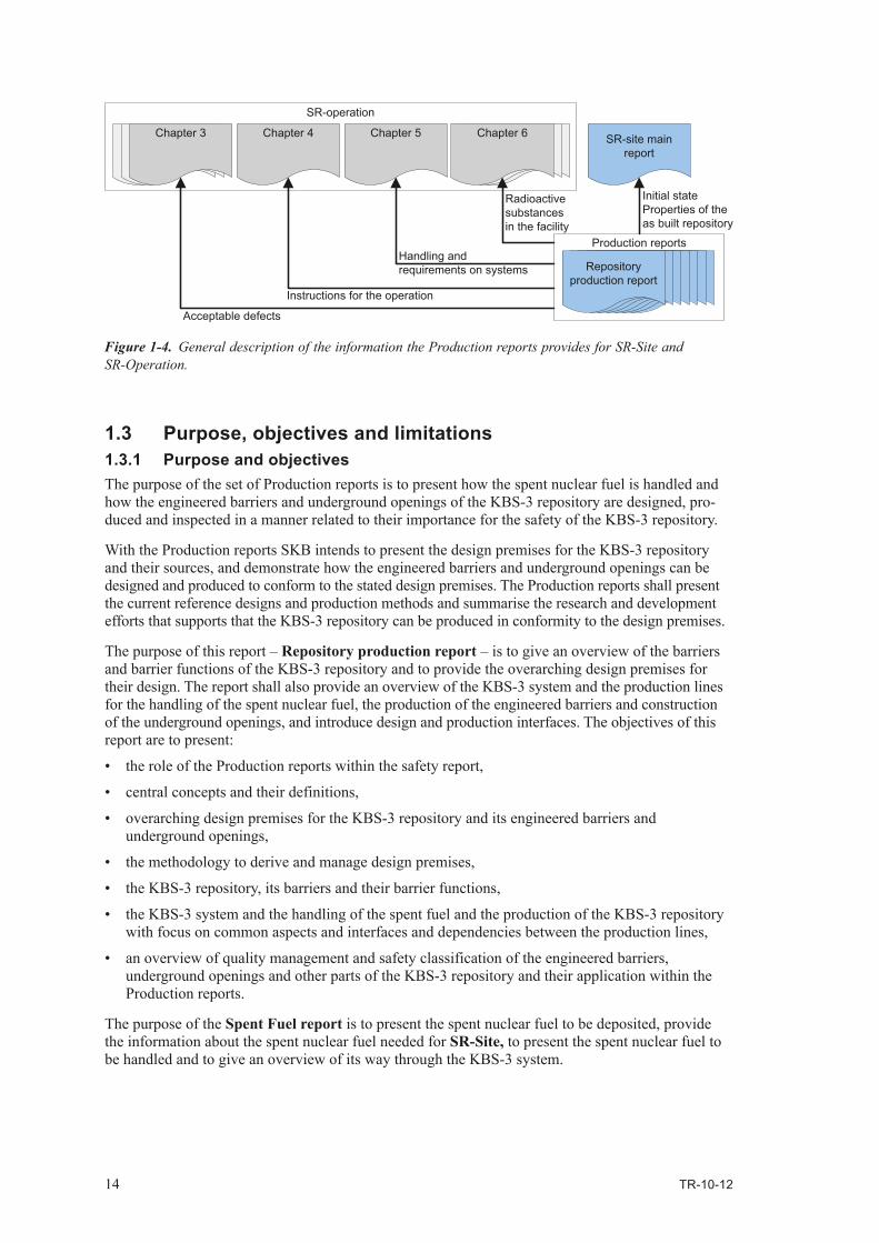
ThestagesoftheproductionlinestakingplaceinthenuclearfacilityoftheKBS-3repositoryfacilityare described in SR‑Operation. The Production reports will provide input to Chapter 4: The operation and quality assurance of the facility and Chapter 5: The facility and its functions of SR‑Operation (gen‑eral part). Further, the Spent fuel report will provide input to Chapter 6: Radioactive substances in the facility of SR‑Operation (general part). An illustration of the information provided by the Production reports for SR‑Site (main report) and SR‑Operation (general part) is given in Figure 1‑4. Technical details and data are provided in each individual report included in the set of Production reports.
Figure 1‑3. The set of Production reports and their short names. The canister, buffer backfill and closure production reports are commonly referred to as the “Engineered barrier” production reports.
Repositoryproductionreport
Spent fuelreport
Canisterproductionreport
Bufferproductionreport
Backfillproductionreport
Closureproductionreport
Undergroundopeningsconstructionreport
Production reports
”Engineered barrier” production reports
Table 1‑1. The set of Production reports and their full and short names.
Full title Short name used within the Production reports
Text in reference lists
Design and production of the KBS-3 repository
Repository production report Repository production report, 2010. Design and production of the KBS‑3 repository. SKB TR‑10‑12, Svensk Kärnbränslehantering AB.
Spent nuclear fuel for disposal in the KBS-3 repository
Spent fuel report Spent fuel report, 2010. Spent nuclear fuel for disposal in the KBS‑3 repository. SKB TR‑10‑13, Svensk Kärnbränslehantering AB.
Design, production and initial state of the canister
Canister production report1 Canister production report, 2010. Design, production and initial state of the canister. SKB TR‑10‑14, Svensk Kärnbränslehantering AB.
Design, production and initial state of the buffer
Buffer production report1 Buffer production report, 2010. Design, production and initial state of the buffer. SKB TR‑10‑15, Svensk Kärnbränslehantering AB.
Design, production and initial state of the backfill and plug in deposition tunnels
Backfill production report1 Backfill production report, 2010. Design, production and initial state of the backfill and plug in deposition tunnels. SKB TR‑10‑16, Svensk Kärnbränslehantering AB.
Design, production and initial state of the closure
Closure production report1 Closure production report, 2010. Design, production and initial state of the closure. SKB TR‑10‑17, Svensk Kärnbränslehantering AB.
Design, construction and initial state of the underground openings
Underground openings construction report
Underground openings construction report, 2010. Design, construction and initial state of the underground openings. SKB TR‑10‑18, Svensk Kärnbränslehantering AB.
1 Commonly referred to as the ”Engineered barrier” production reports.
14 TR-10-12
1.3 Purpose, objectives and limitations1.3.1 Purpose and objectivesThe purpose of the set of Production reports is to present how the spent nuclear fuel is handled and how the engineered barriers and underground openings of the KBS‑3 repository are designed, pro‑duced and inspected in a manner related to their importance for the safety of the KBS‑3 repository.
With the Production reports SKB intends to present the design premises for the KBS‑3 repository and their sources, and demonstrate how the engineered barriers and underground openings can be designed and produced to conform to the stated design premises. The Production reports shall present the current reference designs and production methods and summarise the research and development efforts that supports that the KBS‑3 repository can be produced in conformity to the design premises.
The purpose of this report – Repository production report – is to give an overview of the barriers and barrier functions of the KBS‑3 repository and to provide the overarching design premises for their design. The report shall also provide an overview of the KBS‑3 system and the production lines for the handling of the spent nuclear fuel, the production of the engineered barriers and construction of the underground openings, and introduce design and production interfaces. The objectives of this report are to present:
• theroleoftheProductionreportswithinthesafetyreport,
• centralconceptsandtheirdefinitions,
• overarchingdesignpremisesfortheKBS-3repositoryanditsengineeredbarriersandunderground openings,
• themethodologytoderiveandmanagedesignpremises,
• theKBS-3repository,itsbarriersandtheirbarrierfunctions,
• theKBS-3systemandthehandlingofthespentfuelandtheproductionoftheKBS-3repositorywith focus on common aspects and interfaces and dependencies between the production lines,
• anoverviewofqualitymanagementandsafetyclassificationoftheengineeredbarriers,underground openings and other parts of the KBS‑3 repository and their application within the Production reports.
The purpose of the Spent Fuel report is to present the spent nuclear fuel to be deposited, provide the information about the spent nuclear fuel needed for SR‑Site, to present the spent nuclear fuel to be handled and to give an overview of its way through the KBS‑3 system.
Figure 1‑4. General description of the information the Production reports provides for SR‑Site and SR‑Operation.
Chapter 4Chapter 4Chapter 6Chapter 4Chapter 4 SR-site mainreport
SR-operation
Chapter 3
Handling andrequirements on systems
Instructions for the operation
Initial stateProperties of theas built repository
Production reports
Repositoryproduction report
Chapter 4
Acceptable defects
Chapter 5
Radioactivesubstancesin the facility

TR-10-12 15
The purpose of the “Engineered barrier” production reports and the Underground openings construction report is to provide information on design premises, design, production and construc‑tion and the resulting initial state as a basis for the safety assessment SR‑Site. The “Engineered barrier” production reports and the Underground openings construction report shall also provide information to SR‑Operation concerning the handling, deposition and installation of the engineered barriers and construction of the underground openings.
1.3.2 LimitationsThis report provides a description of the KBS‑3 system and its facilities. Assessments of its safety, environmental impact, costs etc are presented in other documents within or outside the safety report.
The Production reports present how the engineered barriers and underground openings are designed, andproducedtoconformtothestateddesignpremises.Otheraspectsoftheproduction,e.g.workerssafety or logistics are reported elsewhere.
The Production reports present one design of the KBS‑3 repository and its engineered barriers and underground openings that can be produced in conformity to the design premises, alternative designs are reported elsewhere. It is foreseen that the presented design will be developed and improved as a result of technology development and safety assessments. Planned research and development is presentedinSKB’sresearch,developmentanddemonstrationprogrammes(RD&D-programmes).
The Spent fuel report is based on SKB’s reference scenario for the operation of the nuclear power plants and includes a presentation of the spent nuclear fuel that currently is stored in the interim storage facility. Alternative operation scenarios for the nuclear power plants are not included.
The “Engineered Barrier” production reports and Underground openings construction report presentthedesignconsiderationstakenwithrespecttotheapplicationofbestavailablesafetyandradiation protection technique and how they have affected the design. Motivations for the described reference design and methods as being the best available are presented separately.
The Underground openings construction report contains a description of how the repository is adapted to the selected site. The selection of a site for the repository and the location of the other facilitieswithintheKBS-3systemarepresentedinotherdocuments.Furtherdescriptionsoftherockas one of the barriers of the repository are included in the SR‑Site.
The only aspect of control of nuclear material, safeguards, discussed in the Production reports is its impact on the design of the KBS‑3 repository.
1.4 Structure and content1.4.1 This reportThis report sets the production reports in their context and provides the common basis for the Spent fuel report, the “Engineered barrier” production reports and the Underground openings construc‑tion report.
The purposes and limitations of the Production reports and their role in the safety report are presented in this chapter. This chapter also contains an overview of the structure and content of the reports and a presentation of some concepts of importance for the reports.
In Chapter 2 the substantiation of design premises for the KBS‑3 repository is presented. The different kindsofdesignpremisesrelatedtothedifferentlevelsofdetailinthedesignandtheirsourcesarepre‑sented. The treaties, laws and regulations of importance for the design, the spent fuel to be deposited, as well as the approach to substantiate design premises from the results of the safety assessment and technology development are discussed.

16 TR-10-12
In Chapter 3 the functions and considerations SKB has substantiated based on the treaties, laws and regulations as a specification of the KBS‑3 repository, and as guidelines for the design, are presented. The spent fuel to be deposited and its impact on the design are discussed. The purposes, basic designs and barrier functions of the engineered barriers as well as the purpose and functions of the underground openings and plugs are stated.
In Chapter 4 the facilities of the KBS‑3 system and the production lines are introduced. The chapter contains a presentation of the facilities their purposes and main activities as well as an overview of the production lines and their interfaces.
Finally in Chapter 5 an introduction to quality management, safety classification and their application within the production of the KBS‑3 repository is given.
1.4.2 The spent fuel reportThe Spent fuel report comprises a description of the spent fuel to be deposited and the properties of the spent fuel of importance for the design and safety of the KBS‑3 repository. The requirements on the handling of the spent fuel that are related to the design and safety of the KBS‑3 repository are stated. The fuel is not produced but handled within the KBS‑3 system, and the production line in the Spent fuel report comprises a presentation of the handling in accordance with the requirements. Finally, for the initial state the resulting radionuclide inventory and other properties of the encapsu‑lated spent nuclear fuel required for the safety report are presented.
1.4.3 The engineered barrier production reportsThe general flow of information in the “Engineered barrier” production reports can be described as follows:
• designpremises,
• referencedesign,
• conformityofreferencedesigntodesignpremises,
• production,
• initialstate,i.e.theresultsoftheproduction.
The barrier functions and design considerations introduced in Chapter 3 in this report are repeated and forms the basis for the detailed design premises for each engineered barrier given in the “Engineered barrier” production reports. The reference designs of the engineered barriers are specified and their basis discussed. The conformity of the reference designs to the design premises is analysed. The presentation of the production starts with the main parts of the production lines presented in Chapter 4 in this report and an introduction to the reference methods applied in the production. This introduction is followed by more detailed descriptions of the individual stages of the production line. The initial state comprises results of the production and the conformity of the produced engineered barriers to their reference designs and design premises.
1.4.4 The underground openings construction reportThe design premises for the underground openings are presented in the same way as for the engineered barriers, i.e. starting from the functions and considerations presented in Chapter 3 in this report and fol‑lowed by the more detailed design premises. The presentation of the design premises is followed by a descriptionoftherockengineeringandsiteadaptationincludingapresentationoftherockengineeringmethodology SKB intends to apply. The reference designs of the underground openings comprise their site specific layouts and properties, and their conformity to the design premises. The production part in the Underground openings construction report comprises a presentation of the reference methods to construct and inspect the different underground openings and an overview of possible mitigation measures that may be used to rectify non‑conformity to the design premises. As for the engineered barriers the results of the construction comprise the initial states of the different underground openings and their conformity to their reference designs and design premises.

TR-10-12 17
1.5 Central conceptsIn this section some concepts of importance for the Production reports are defined and explained. Concepts are written in bold italics, definitions are written in italics and explanations are written in normal text. The concepts are introduced in alphabetic order. Regarding quality management SKB hasdecidedtoapplythevocabularyinthestandard/ISO9000:2005/.
barrier: physical confinement of radioactive substances Applicable in nuclear facilities in connection with their construction, possession and operation / SSMFS 2008:1 definitions/. an engineered (man‑made) or natural part of final repository that has barrier function Applicable in final repository / SSMFS 2008:21 2,3 §§ with general recommendations/.
barrier function: the way a barrier functions to contribute to contain the radioactive substances or to prevent or retard their dispersion Also includes the capability of a barrier to preserve the function of other barriers.
conformity: fulfilment of a requirement /ISO9000:2005/.
design premises: information forming a necessary basis for designDesignpremisescompriserequirementsandotherpremisesforthedesign.Requirementsexpressneedsorexpectations.Otherpremises comprise quantitative information on features, performance, events, loads, stresses, combi‑nations of loads and stresses and other information, e.g. regarding environment or adjacent systems necessary for the design. In the Production reports design premises is used as a common term for all information required for the design, and no distinction is made between requirements and premises.
initial state: the properties of the spent fuel at the time for encapsulation, the properties of the engineered barriers once they have been finally placed in the final repository and will not be further handled within the repository facility, the properties of the underground openings at final installation of buffer, backfill or closure.
inspection: conformity evaluation by observation and judgement accompanied as appropriate by measurement, testing or gauging /ISO9000:2005/.
organisation: group of people and facilities with an arrangement of responsibilities, authorities and relationships/ISO9000:2005/.
procedure: specified way to carry out an activity or process/ISO9000:2005/.
process: set of interrelated or interacting activities which transforms inputs to outputs/ISO9000:2005/.
product: result of a process /ISO9000:2005/.
production line: The ordered sequence of stages in the handling of the spent nuclear fuel and production oftheengineeredbarriers.Thesuccessive–asmoreinformationontheconditionsintherockgetsavailable – design, site adaptation and construction of underground openings.
qualification: investigation and demonstration which shows that a person or a testing, processing or integration process can fulfil its specified tasks / SSMFS 2008:13/.
qualification process: process to demonstrate the ability to fulfil specified requirements /ISO9000:2005/.
quality plan: document specifying which procedures and associated resources shall be applied by whom and when to a specific project, product, process or contract /ISO9000:2005/.
record document: document stating results achieved or providing evidence of activities performed /ISO9000:2005/.
reference design: a design that is valid from a defined point in time until further notice. The established reference design shall be used as the precondition for technical development, further design and the analyses of safety, radiation protection and environmental impact. A reference design may be either general or site specific.
requirement: a need or expectation that is stated, generally implied or obligatory /ISO9000:2005/See design premise above and Chapter 2.

18 TR-10-12
specification: document stating requirements/ISO9000:2005/SeedesignpremiseaboveandChapter 2.
test: determination of one or more characteristics according to a procedure /ISO9000:2005/.
verification: confirmation, through the provision of objective evidence that specified requirements have been fulfilled /ISO9000:2005/.
validation: confirmation, through the provision of objective evidence that the requirements for a specific intended use or application has been fulfilled /ISO9000:2005/.

TR-10-12 19
2 Substantiation of design premises
2.1 IntroductionThe “Engineered barrier” production reports and Underground openings construction report shall contain the design premises for the engineered barriers and underground openings of the KBS‑3 repository. The design premises are derived from the following sources:
• internationaltreaties,
• Swedishlawsandregulations,
• stakeholderdemandsandagreements,
• thepropertiesofthespentnuclearfuel,
• thechosenmethodforfinaldisposal,thebarriersofthefinalrepositoryandtheirbarrierfunctions,couplings and interdependencies between them and decisions made in the design,
• theproductionandhandlingoftheengineeredbarriersandtheconstructionoftheundergroundopenings,
• therepositorysite,
• thegeneralknowledgeaboutprocessesthatmayimpactthebarrierfunctionsandthesafetyoftherepository,
• thesafetyassessment,primarilythelong-termsafetybutalsotheoperationalsafetypart.
Therearedifferentkindsofdesignpremisesrelatedtothedifferentsourcesandlevelsofdetailinthe design.
The most general, highest level, specify the problem to be solved and the basic principles that shall be appliedinthedesign.Thesetopleveldesignpremisesarebasedonlawsandregulations,stakeholderdemands and decisions and agreements.
The next two levels of detail provide high‑level specifications of the method and system to solve the problem. At these two levels the KBS‑3 method and KBS‑3 repository and its barriers are specified and their purpose and functions are described. The design premises on these levels are based on the basic principles to be applied, laws and regulations, the properties of the spent nuclear fuel and the chosen method to manage the spent fuel.
Finally, the design premises expressing the properties that the different components of the sub‑systems, i.e. the barriers and parts of the KBS‑3 repository, must have in order to maintain the functions are speci‑fied. These design premises specify the properties to be designed and provide quantitative information on features, events and processes that shall be considered when determining a reference design. The designpremisesonthislevelarebasedontherequiredfunctionsandfeedbackfromperformedsafetyassessments and technical development. Within the Production reports these design premises have been divided into: design premises related to the functions in the KBS‑3 repository, design premises from other parts of the KBS‑3 repository and design premises related to the production and operation.
TomanagethedifferentkindsofdesignpremisesandtheirinterdependenciesSKBhasdevelopedarequirementmanagementsystem–RMS/MorénandWikström2007/withinwhichthedesignpremises are reviewed, settled and documented. Within the RMS information such as review status, sources,translationiskeptforeachdesignpremise.InFigure2-1thedifferentkindsofdesignpremises, their sources and their related level of detail in the design are illustrated together with an example from SKB’s RMS.
The design premises specifying the problem to be solved by the KBS‑3 repository and the functions of the KBS‑3 repository and its engineered barriers and underground openings are presented in this report – Repository production report. The design premises for the reference designs are presented in the “Engineered barrier” production reports and the Underground openings construction report.

20 TR-10-12
2.2 Laws and regulations and stakeholder demandsThefinalrepositoryshallconformtotherequirementsinrelevantlawsandregulations.Stakeholderdemands expressed in SKB’s guiding principles: safety, efficiency and responsiveness shall be considered in the design. Further, the final repository for spent nuclear fuel shall be adapted to the scope and time schedule of the Swedish nuclear power programme.
The international treaties and national laws and regulations relevant for the design of a final reposi‑tory for spent nuclear fuel are the following.
International treaty:
• JointConventionontheSafetyofSpentFuelManagementandontheSafetyofRadioactiveWaste Management.
Nationallaws:• ActonNuclearActivities/SFS1984:3/.• RadiationProtectionAct/SFS1988:220/.
Regulations:• SSMFS2008:1Regulationsconcerningsafetyinnuclearfacilities.• SSMFS2008:12 Regulations concerning physical protection of nuclear facilities.• SSMFS2008:21Regulationsconcerningsafetyinconnectionwiththedisposalofnuclearmaterial
and nuclear waste.• SSMFS2008:37 Regulations on the protection of human health and the environment in connection
with the final management of spent nuclear fuel and nuclear waste.
Figure 2‑1. Different kinds of design premises, their sources and the corresponding degree of detail in the design with an example from SKB’s RMS.
Design premises Sources and level of detail Example
The KBS-3 repository (presented in this report)
The KBS-3 repository
Problem (presented in this report) Level 1
Level 2 and 3
(presented in the ”Engineered barrier” production and Underground openings construction reports)Level 4
Requirements expressingobjectives and principles forthe design.
Requirements expressing thefunctions the repository shallhave to conform to theobjectives and principles.
Requirements expressing thefunctions the barriers andother parts shall have for therepository to maintain itsfunctions.
Properties and parameters tobe designed and premises forthe design from:- the safety assessment,- the other barriers,- the production and operation
Insert - material composition,material properties anddimensions.The canister shall withstandan isostatic load of 45 MPa,being the sum of maximumswelling pressure andmaximum groundwaterpressure.
The post-closure safety of thefinal repository shall be basedon several barrier functionsthat are maintained through asystem of passive barriers.
The final repository shallcontain the spent nuclear fueland isolate it from thebiosphere.
The canister shall withstandthe mechanical loads that areexpected to occur in the finalrepository.
The components of the engineeredbarriers and their properties
The layout and properties of theunderground openings
The required functions and resultsfrom the safety asessment, research
and development
The engineered and natural barriersand other parts of the final repository
Laws and regulationsThe KBS-3 method
The spent nuclear fuel
Laws and regulationsThe KBS-3 method
The spent nuclear fuel
Problem to be solved and principles tobe applied in the design
Laws and regulationsStakeholder demands
Reference design

TR-10-12 21
In addition, the following treaties and act, which primarily concern the documentation and inspection of nuclear material and thus the operation of the KBS‑3 repository facility, will indirectly affect the design of the final repository.
International treaties:• TreatyontheNon-ProliferationofNuclearWeapons.• TreatyestablishingtheEuropeanAtomicEnergyCommunity(EuratomTreaty).
Nationallaw:• ActonInspectionsaccordingtoInternationalAgreementsonNon-proliferationofNuclear
Weapons /SFS 2000:140/.
The Swedish Environmental Code /SFS 1998:808/ shall be applied for all activities that may impact the environment. Its main purpose is to provide for a sustainable development which implies that the current and future generations shall be assured a healthy and good environment. It includes the common rules of consideration that shall be applied to achieve this. The purpose of the environmental codeandtherulesofconsiderationshallbekeptinmindinthedesignthefinalrepositoryforspentnuclear fuel.
In addition, the underground openings as well as methods and technical systems to produce the different partsofthefinalrepositoryshallconformtotheWorkEnvironmentAct/SFS1977:1160/withregula‑tions. The design of the underground openings shall also conform to the Planning and Building act /SFS1987:10/andtheActonTechnicalRequirementsforConstructionworks/SFS1994:847/withregulations.
The repository shall be constructed to conform to the requirement that spent nuclear fuel and nuclear material that is not going to be reprocessed and re‑used shall be finally deposited / SFS 1984:3 10, 14 §§, Joint convention on the Safety of Spent Fuel management and on the Safety of Radioactive Waste Management/. Principles of particular importance for the safety of the final repository and having a strong influence on the design are the multi‑barrier principle, the defence‑in‑depth principle and the radiation protection principles to protect both human health and the environment and both current and future generations.
According to the multi‑barrier principle the safety of the repository shall be maintained through a system of passive barriers which, in one or several ways, contribute to the containment, prevention or retardation of dispersion of radioactive substances, either directly or by protecting other barriers. The barrier system shall be designed to withstand features, events and processes that can affect their post‑closure performance and the safety shall be maintained in spite of a single deficiency in a barrier / SSMFS 2008:21 2, 3, 5, 7 §§/. This principle and these paragraphs are important for substantiating the functions of the KBS‑3 repository and its barriers.
According to the defence‑in‑depth principle nuclear accidents shall be prevented through a facility‑specific design which shall incorporate multiple barriers as well as a facility‑specific defence‑in‑depth system. The defence in depth system shall comprise several, overlapping levels of technical equipment, operational measures and administrative procedures to protect the facility’s barriers and to maintain their effectiveness as well as to protect the surroundings if the barriers should not function as intended / SSMFS 2008:1 1 chp 2 §, 2 chp 1 §/. The defence‑in‑depth principle will impact the design and operation of the final repository facility. Regarding the final repository the construction, manufac‑turing, handling, testing and inspection of the final repository barrier system shall be dependable.
According to the radiation protection principles human health, and the environment, shall be pro‑tected from detrimental effects of ionising radiation throughout the entire handling and execution of the various stages in the management of the spent nuclear fuel, and in the post‑closure period. Man and the environment both within and outside the national borders shall be protected and predictable future impact on human health must not exceed currently acceptable levels / SFS 1988:220 1, 6 §§; SSMFS 2008:37 3, 5, 6 §§, Joint Convention on the Safety of Spent Fuel Management and on the Safety of Radioactive Waste Management Article 1 ii, Article 4/.
SKB’s objectives for a system to manage spent nuclear fuel and the principles which shall form the basis for the system design as documented within the requirement management system are presented in / SKBdoc 1241883/.

22 TR-10-12
2.3 The spent nuclear fuel to be depositedOnepropertyofthespentnuclearfuel,whichcontributestothelong-termsafetyandisofessentialimportancefortheKBS-3method,istheformofthespentnuclearfuel.Thebulkofthefueltobedeposited consists of uranium oxide, which has very low solubility in a KBS‑3 repository environ‑ment. With respect to this the fuel to be deposited in a KBS‑3 repository shall be in oxide form or in some other form with similar low solubility in the groundwater that may penetrate deposited canisters.
The spent nuclear fuel to be finally deposited form an important basis for the design of the final repository. Parameters that will affect the design of the final repository are the radiotoxicity and decay power and the total amount of spent fuel to be deposited. Both the radiotoxicity and decay power are determined by the radionuclide inventory and will decrease as the radioactive decay proceeds. Also the dimensions of the fuel assemblies will impact the design.
The final repository shall provide protection against the harmful effects of radiation for as long as is necessary with respect to the radiotoxicity of the spent nuclear fuel. The radiotoxicity of the spent nuclear fuel and the time required for it to decay to levels corresponding to the radiotoxicity of the uranium ore once used to manufacture it is illustrated in Figure 2‑2. The time for the radiotoxicity of the spent fuel to decay to naturally occurring levels is an important input to the design of the KBS‑3 repository and its engineered barriers.
The requirement that the engineered barriers shall maintain their barrier functions with respect to features, events and processes that can affect their performance has resulted in a maximum allowed temperature in the KBS‑3 repository. The maximum allowed temperature will together with the total amount of spent fuel and the number of fuel assemblies in each canister determine the minimum size of the final repository. The temperature in the final repository will depend on the decay power of the spent nuclear fuel, the dimensions and thermal properties of the engineered barriers, the distances betweenthedepositedcanistersandthethermalpropertiesofthehostrock.Thedecaypowerwilldecreasewithtime.Consequentlythetimeperiodfromwhenthefuelassembliesaretakenoutofthenuclear power reactor until they are encapsulated and deposited in the final repository will impact the size of the repository. The fuel parameters of importance for the design of the final repository are further discussed in the Spent fuel report, Section 2.3.
Figure 2‑2. Radiotoxicity on ingestion of uranium ore (blue line), and of all fractions that arise when the same quantity of uranium mineral is used in the nuclear fuel cycle (red line). The different fractions comprise the spent fuel, the depleted uranium and the uranium daughters that are separated in the uranium mill, from /Hedin 1997/.
1
10
100
1,000
10,000
1 10 100 1,000 10,000 100,000 1,000,000
Time (years)
Rad
ioto
xici
ty (
rela
tive
scal
e)
Total, all fractions in thenuclear fuel cycle
Spent fuel, 1 tonne
Uranium daughters,equivalent to 8 tonnes
Depleted uranium, 7 tonnes
Natural uranium withdaughters, 8 tonnes
0.1
0.0110 mill.0.1

TR-10-12 23
2.4 Functions of the KBS‑3 repository and design considerations2.4.1 Functions of the KBS‑3 repositoryThe safety and radiation protection principles introduced in Section 2.2 and the properties of the spent nuclear fuel, mainly its radiotoxicity and its decay with time, constitute the basis for the substantiation of the functions of the KBS‑3 repository. The purpose of the final repository is to protect man and the environment from unacceptable radiological impact. In the final report of the KBS (nuclear fuel safety) project – Final storage of spent nuclear fuel – KBS‑3 / SKBF/KBS 1983/ which has given the name to the KBS‑3 method – it is stated that:
“This can be achieved in two ways. One is to contain the radioactive substances for a sufficiently long period of time to allow the process of decay to reduce activity to acceptable levels. The other is that the radioactive substances are diluted, i.e. released and dispersed so slowly that the maximum concentrations that can reach man are acceptably low.”
In the current regulations the term diluted is not used but it is stated that the functions of the barriers of a final repository shall be: to in one or several ways, contribute to contain the radioactive substances or to prevent or retard their dispersion / SSMFS 2008:21 3 §/. In a final repository based on the KBS‑3 method containment as well as prevention or retardation of dispersion of radioactive substances are employed to protect man and the environment from radiation. This approach is common for final repositories developed in many other countries.
In addition to the safety and radiation protection principles and the radiotoxicity of the spent nuclear fuel,thehostrockandgeologicalconditionsareimportantwhendeterminingthefunctionsofafinalrepository. The functions of the KBS‑3 repository and its engineered barriers and underground open‑ings constitute a specification of a KBS‑3 repository, and are high level premises for the design of its engineered barriers and underground openings. The functions of a KBS‑3 repository and its barriers and other parts are presented in Chapter 3 in this report.
2.4.2 Design considerationsFor some design premises quantitative criteria for the evaluation of the conformity of the design to the design premises are provided. Based on the functions of the final repository quantitative premises for the design of the engineered barriers and underground openings can be substantiated. In some cases the functions as such can be verified against quantitative criteria, i.e. for the protection of man and theenvironmentfromionisingradiationquantitativedoseand/orriskcriteriaarestated.However,there are also some design premises for which no absolute quantitative criteria for the conformity of the design can be given. Examples are that the technical solutions shall be well‑tried or tested and be cost‑effective. In the Production reports these design premises are referred to as design considerations.
The design considerations are presented in Section 3.9 in this report. They shall be regarded in the design of the engineered barriers and underground openings and in the development and choice of methods to manufacture, install, construct and inspect them.
2.5 Design premises from safety assessment, design and technology development
2.5.1 General approachThe development of the design premises and design of the KBS‑3 repository, its engineered barriers and underground openings, has been and is an iterative process with several loops of design, technology development and assessment. In addition, for the underground openings the successively more detailed site descriptive model is an important design premise for the development of the design.
The high level design premises are in principle expressed in laws and regulations, or based on the properties of the spent nuclear fuel or the chosen method to finally dispose the spent nuclear fuel. These high level design premises for a KBS‑3 repository are presented in Chapter 3 in this report.

24 TR-10-12
However,thesubstantiationoflowerleveldesignpremisesforthedesignoftheproperties,e.g.geometry, material composition and strength, of the engineered barriers and underground openings requireinputandfeedbackfromtechnicaldevelopmentandsafetyassessments.Thepropertiesshallprovide the required functions and be technically feasible to achieve. A flow chart for the iterative process of substantiation of design premises, design and technology development and safety assess‑ment is given in Figure 2‑3.
The lower level design premises stating the properties and parameters to be designed and the premises the design shall conform to are in the Production reports divided into design premises:
• relatedtothefunctionsintheKBS-3repository,
• fromotherpartsoftheKBS-3repository,
• relatedtotheproductionandoperation.
The sources of these categories of design premises and where they are discussed and presented within the Production reports is presented in Table 2‑1.
Figure 2‑3. The iterative process of substantiation of design premises from design, technology development and safety assessment.
Table 2‑1. The different categories of detailed design premises, their sources and references to where they are discussed and presented.
Design premise category Source Discussed and presented in
Related to the functions in the KBS-3 repository
Assessment of long-term safety Substantiation discussed in Section 2.5.2 (this report)Design premises presented in Sections 2.3 of the “Engineered barrier” production reports1 and the Underground openings construction report
From other parts of the KBS-3 repository
Spent nuclear fuelTechnology development and reference designs and methods
Substantiation discussed in Section 2.5.3 (this report)Design premises presented in Sections 2.3 of the “Engineered barrier” production reports1 and the Underground openings construction report
Related to production and operation
Technology development and reference designs, methods and proceduresOperational safety assessment
Substantiation discussed in Sections 2.5.4 and 2.5.5 (this report)Design premises presented in Sections 2.3 of the “Engineered barrier” production reports1 and the Underground openings construction report
1 For the plug in deposition tunnels Section 2.5 in the Backfill production report
Technical feasibilityDesign and design analysis
Technology development and tests
Safety assessment
Design premises for the design of the engineered barriersDesign premises for the site adaptation and design of the underground openings
develops
develops
The KBS-3 repository and its safety functionsThe engineered barriers and their barrier functions
The underground openings and their functions
Design premisesPrinciples to be applied from treaties, laws and regulations

TR-10-12 25
Regarding the design premises from other parts of the KBS‑3 repository, they are stated in the production report for the part – i.e. spent fuel, engineered barrier or underground opening – imposing the premise, and repeated and verified in the production line for the part that shall conform to the design premise.
In addition to the design premises for the design of the different parts of the KBS‑3 repository there are premises for the development of the methods to produce and construct them. The properties that contribute to the functions and safety of the KBS‑3 repository shall be possible to achieve by proven or well‑tested technology. The production and operation shall be dependable, cost‑effective and car‑ried out in the prescribed rate. The detailed premises for the development of methods are presented in the chapters presenting the production and construction respectively in the “Engineered barrier” production reports and Underground openings construction report.
It is foreseen that the lower level design premises derived from the safety assessment, technical develop ment, production and construction will develop as a result of further assessments, research anddevelopment.Tomakethedevelopmenttraceablealldesignpremisesandalsothereferencedesigns are documented within SKB’s requirement management system.
2.5.2 Design premises related to the functions in the KBS‑3 repositoryThe design premises related to the functions in the KBS‑3 repository are based on the results from the assessment of the long‑term safety.
Any design must start from a specification of what shall be achieved and the required functions. The design shall have the capability of sustaining the functions. Whether a specific design results in a final repository that conform to the safety criteria can only be determined through a safety assess‑ment where all parts of the system are evaluated together.
In the general recommendations to SSM’s regulations concerning safety in connection with the disposal of nuclear material and nuclear waste, SSMFS 2008:21, it is stated that: “The safety assessment should also aim at providing a basic understanding of the repository performance on different time‑periods and at identifying requirements regarding the performance and design of different repository components.”
The safety assessment methodology and methods for deriving design premises from the assessment have gradually been developed. In the most recent assessment of long‑term safety, SR‑Can / SKB 2006/, the roles through which the repository components contribute to safety were expressed as safety functions. Associated to the safety functions are safety function indicators which are measurable or calculable quantities through which the safety functions can be quantitatively evaluated. For some of the safety function indicators it was also possible to specify function indicator criteria which are quantitative limits used to assess whether the safety function is maintained or not.
Further, in the general recommendations to SSM’s regulations concerning safety in connection with the disposal of nuclear material and nuclear waste, SSMFS 2008:21, it is stated that “Based on scenarios that can be shown to be especially important from the standpoint of risk, a number of design basis cases should be identified”.Preliminarydesignbasescasesandotherdesignfeedbackweregivenin the safety assessment report SR‑Can / SKB 2006/ and have been further developed in a specially dedicatedreporttitled“DesignpremisesforaKBS-3Vrepositorybasedonresultsfromthesafetyassessment SR‑Can and some subsequent analyses” / SKB 2009/. This report comprise design premises for the design of the engineered barriers and underground openings related to their function in the KBS-3repository,andisthusakeyreferencetotheProductionreports.ItiswithintheProductionreports referred to as Design premises long‑term safety.
The approach to substantiate design premises from the assessment of the long‑term safety and the resulting design premises are further discussed in Design premises long‑term safety.
2.5.3 Design premises from other parts of the KBS‑3 repositoryDesignpremisesfrom,orimposedby,otherpartsconcerntechnicalfeasibility.Interactionsandinter-dependencies between the different parts occurring in the KBS‑3 repository after the parts are finally installed in the repository are addressed within the assessment of the long‑term safety and expressed in the design premises from the assessment.
26 TR-10-12
Tobetechnicallyfeasiblethedifferentpartsoftherepositorymustfit,andwork,togethersothatthey can acquire the properties needed to provide the required functions. Thus, the reference design ofonecomponentmayconstituteadesignpremiseforanother.Forexample,inorderforthebackfillindepositiontunnelstomaintainitsfunctionsasufficientlyhighdensityofthebackfillmaterialisrequired.Theresultingbackfilldensitydependsontheinstalledmaterialmassandonthedepositiontunnelvolume,andalsoonotherpropertiesofthetunneltobebackfilled.Thereferencedesignofthebackfillisthusadesignpremiseforthedepositiontunnels.
In practice, the designs of the different parts are mutually adapted to achieve a technically feasible and robust solution. An exception is the spent nuclear fuel for which the design cannot be altered. However,requirementsonthehandlingofthespentfuelmaybeimposedbytheotherpartsoftheKBS‑3 repository.
2.5.4 Design premises related to production and operationThe properties of importance for the function in the KBS‑3 repository shall be possible to achieve and inspect in the production. Further, to achieve a reliable production, loads occurring during handling and transportationshallbeconsideredinthedesignofthecanister,buffer,backfillandclosurecomponents.
According to the general recommendations to SSM’s regulations concerning safety in connection with the disposal of nuclear material and nuclear waste, SSMFS 2008:21: “… information, such as on manufacturing method and controllability, … should be used to substantiate the design basis such as requirements on barrier properties.”.
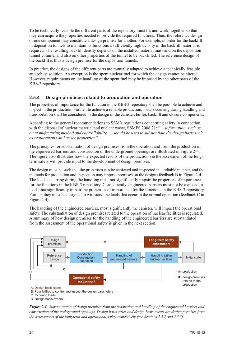
The principles for substantiation of design premises from the operation and from the production of the engineered barriers and construction of the underground openings are illustrated in Figure 2‑4. The figure also illustrates how the expected results of the production via the assessment of the long‑term safety will provide input to the development of design premises.
The design must be such that the properties can be achieved and inspected in a reliable manner, and the methodsforproductionandinspectionmayimposepremisesonthedesign(feedbackBinFigure2-4.The loads occurring during the handling must not significantly impair the properties of importance for the functions in the KBS‑3 repository. Consequently, engineered barriers must not be exposed to loads that significantly impair the properties of importance for the functions in the KBS‑3 repository. Further,theymustbedesignedtowithstandtheloadsthatoccurinthenormaloperation(feedbackCinFigure 2‑4).
The handling of the engineered barriers, most significantly the canister, will impact the operational safety. The substantiation of design premises related to the operation of nuclear facilities is regulated. A summary of how design premises for the handling of the engineered barriers are substantiated from the assessment of the operational safety is given in the next section.
Figure 2‑4. Substantiation of design premises from the production and handling of the engineered barriers and construction of the underground openings. Design basis cases and design basis events are design premises from the assessments of the long‑term and operational safety respectively (see Sections 2.5.2 and 2.5.5).
Reference design
Handling of enginnered barriers
Handling within nuclear facilities Initial state
Long-term safety assessment
Design premises
Operational safety assessment
A. Design basis casesB. Possibilities to control and inspect the design parametersC. Occuring loadsD. Design basis events
production
A
BC
Ddesign premisesrelated to theproduction
ProductionConstructionInspection

TR-10-12 27
2.5.5 Design premises related to the safe operation of the repository facilityThe operational safety of the repository facility refers to technical, organisational and administrative measures to prevent i) the canister from being damaged in such a way that the containment is breached and radioactive substances dispersed, or ii) the occurrence of radiation doses higher than those accepted for normal operation of the facility. This means that the canister must be tight when it arrives to the repository facility and remain tight during handling within the facility. As a consequence of this the repository facility and its technical systems and equipment must be designed so that the canister cannotbeexposedtoloadsandstressesthatmayresultinleaks.Thecanisterinturnmustbedesignedtowithstandtheloadsitmaybeexposedto,notonlyduringnormaloperationbutalsoforlesslikelyeventsthatmayoccurinthefacility.Theloadsoccurringduringnormaloperationandlesslikelyeventsconstitute design premises for the canister.
To minimise the radiation doses to the personnel within the facility, and also due to the requirements on reliability and operational stability, it is desirable that the canisters and their contents are always fit for deposition and should not need to be retrieved for repair or replacement of the canister. Even if itwillnotresultincanistersnotfitfordeposition,damagesoninstalledbufferorbackfillindepositiontunnels that will necessitate retrieval of deposited canisters from the deposition holes shall be avoided.
According to the general recommendations to SSM’s regulations concerning safety in nuclear facilities the safety analysis of the KBS‑3 repository facility should include: “a set of events or scenarios … which can affect the function of the defence‑in‑depth system and, thereby, ultimately have a radiologi‑cal impact on the environment. The events shall be divided into classes based on their expected frequency. TheeventclassesaredenominatedHfollowedbyaninteger,whereahighernumberindicateslowerfrequency of occurrence. Based on the classes design basis events should be identified.
SKB has classified events during normal operation and events that may occur during the lifetime of thefacilityasH1andH2eventsrespectively,seeSR‑Operation (general part), Chapter 3. In accord‑ance to the discussion above the systems handling the canister and the canister shall be designed so thecanisterisfitfordepositionforalleventsclassifiedasH1orH2events.Thebufferandbackfillin deposition tunnels and the systems of importance for their properties shall be designed so that H1orH2eventswillnotresultinthatdepositedcanistersmustberetrievedandbroughtbacktotheencapsulationplantforrepairorreplacement.However,damagesonthebufferthatrequirethatthecanisterisbroughtbacktoaprevioushandlingstageareacceptableifthecanistersarestillfitfordeposition.DamagesonthebufferorbackfillthatresultinretrievalofallcanistersinadepositiontunnelareunacceptableforH1orH2events.
UnanticipatedandunlikelyeventsthatarenotexpectedtooccurareclassifiedasH3andH4events,respectively, see SR‑Operation (general part), Chapter 3. The canister shall be designed to remain tightforeventsclassifiedasH3orH4events.ShouldaH3orH4eventoccuritshallbereportedtoSSM and its consequences analysed. If the properties of the canister required for it to sustain its bar‑rier functions in the final repository are jeopardised it shall be returned to the encapsulation plant for repairorreplacement.Furthermore,bufferorbackfillthatareanticipatednottosustaintheirbarrierfunctionsasaresultofaH3orH4eventshallbereplacedanddepositionholeswithunacceptabledamages not used for deposition.

TR-10-12 29
3 The KBS‑3 repository
3.1 The KBS‑3 repository and its functions3.1.1 Definitions, purpose and basic designA KBS‑3 repository is a final repository for spent nuclear fuel in which:
• thespentnuclearfuelisencapsulatedintight,corrosionresistantandloadbearingcanisters,• thecanistersaredepositedincrystallinerockatadepthof400–700metres,• thecanistersaresurroundedbyabufferwhichpreventstheflowofwaterandprotectsthem,• thecavitiesintherockthatarerequiredforthedepositionofcanistershavebeenbackfilledandclosed.
All spent nuclear fuel from the Swedish nuclear power programme which shall not be reused shall be encapsulated, deposited and finally stored in the KBS‑3 repository. After closure, the KBS‑3 repository shall contain the spent nuclear fuel and isolate it from man and the environment. If the containment is breached, the final repository shall prevent or retard the dispersion of radioactive substances so that the ionising radiation, if some of the radioactive substances finally reach the environment at the surface, does not cause harm.
AKBS-3repositorycomprisestherockattherepositorysite,thecanisterscontainingspentnuclearfuel,buffer,backfillandclosuresaswellasengineeredandresidualmaterialsthatremainintherockoncetheundergroundopeningshavebeenbackfilledandclosed.
In a KBS‑3 repository, the canisters with spent nuclear fuel can be deposited either horizontally in adrift(KBS-3H)orverticallyindepositionholes(KBS-3V).Thereferencealternativeisverticaldeposition. A closed KBS‑3 repository with vertical deposition of the canisters, and its natural and engineered barriers and parts is illustrated in Figure 3‑1.
Figure 3‑1. The KBS‑3 repository after closure with its natural and engineered barriers and parts without barrier functions.
Repository site KBS-3 repository facility
KBS-3 repository
Ground area
Host rockNatural barrier
Technical systemsSub-surface facility
Surface facility
CanisterEngineered barriers
BackfillBuffer
Closure(borehole)
Closure(tunnel)
Parts without barrier functionsUnderground openings Plug
Activities

30 TR-10-12
All spent nuclear fuel from the operation of the twelve licensed Swedish nuclear power plants – both existing and arising from the future operation of the ten remaining reactors – and from the Ågesta reactor, which is not reprocessed and re‑used shall be deposited in the KBS‑3 repository. The KBS‑3 repositoryshallalsoaccommodatefuelresiduesfromtheStudsvikfacility.Inthefollowingthisspentfuel is referred to as the spent fuel from the currently approved Swedish nuclear power programme.
3.1.2 The functions and properties of the KBS‑3 repositorySKB has based on the treaties, laws and regulations presented in Section 2.2 substantiated the following functions and considerations as a specification of the KBS‑3 repository, and as guidelines for the design of its engineered barriers and underground openings. The functions and considerations are high level design premises (level 2 in Figure 2‑1) and are written in italics.
In line with the multi‑barrier principle and radiation protection principles, the KBS‑3 repository shall:• contain the spent nuclear fuel and isolate it from the biosphere,• if the containment is breached – prevent and retard the dispersion of radioactive substances so
that the ionising radiation, if some of the radioactive substances finally reach the environment at the surface, does not cause harm,
• have a system of passive barriers which, in one or several ways, shall contribute to contain, prevent or retard the dispersion of radioactive substances, either directly, or indirectly by protect‑ing other barriers in the barrier system,
• provide protection against the harmful effects of radiation for as long as the radiotoxicity of the spent nuclear fuel is significantly higher than the radiotoxicity of naturally occurring uranium ores.
Further:• Measures taken to facilitate access, surveillance or retrieval of disposed nuclear fuel, or to
impede intrusion, shall not be detrimental to the safety of the final repository.
In line with the principles stated in the international treaty “Joint Convention on the Safety of Spent Fuel Management and on the Safety of Radioactive Waste Management” the following shall be considered in the design of the KBS‑3 repository.• The barriers of the final repository shall be passive.• Consideration shall be given to unintentional intrusion in the design of the final repository so
that the repository site after closure of the repository facility can be utilised without compromis‑ing the freedom of action, needs and aspirations of future generations.
• On completion of deposition, it shall be technically feasible for the final repository facility to be closed.
In line with the defence‑in‑depth principle and the principle to apply the best available technique the following shall be considered in the design of the KBS‑3 repository.• The barrier system of the final repository shall be capable of withstanding malfunctions and
features, events and processes that could have a detrimental impact on their functions.• The construction, manufacturing, deposition, installation and non‑destructive testing of the final
repository barrier system shall be reliable and operationally stable.• Among technically feasible alternative designs, techniques and measures, those alternatives which
in the short term best restrict radiation doses to human‑beings and which in the long term are judged to offer the best protective capability shall be selected.
In line with non‑proliferation principles and the Euratom Treaty the final repository facility shall:• be well protected and guarded against intrusion and illegal diversion of nuclear material.• be accessible for and be provided with necessary means for the inspection of nuclear material.
This will to some extent affect the design of the final repository.

TR-10-12 31
It is important to recognise that it is the demands stated in the laws and regulations that the final reposi‑tory shall conform to. The functions and considerations stated above constitute guidelines for the design, and are intended as a means to achieve designs that conform to laws and regulations. The treaties, laws and regulations used as the basis for this high level specification of the KBS‑3 repository are described in / SKBdoc 1241883/.
According to the reactor owners, and SKB’s own demands the final repository shall:• accommodate all spent nuclear fuel from the currently approved Swedish nuclear power
programme,• shall have a high level of quality and be cost‑effective,• be flexible for alternative designs within the KBS‑3 method.
Further:
• The final repository shall be constructed and the final repository facility operated for a limited period of time adapted to the operating times of the nuclear power plants.
AsstatedinSection2.2theenvironmentalcodeandtherulesofconsiderationshallbekeptinmindinthe design of the final repository for spent nuclear fuel. This means that environmental impact such as emissions into water and air, noise and vibrations and impact on groundwater shall be considered in the design and development of methods for construction, manufacturing, installation and inspections. Further, the consumption of raw materials and energy shall be considered and – with respect to the safety of the final repository – as far as possible be limited.
3.1.3 The engineered barriers and other parts of the KBS‑3 repositoryThe functions of the final repository shall be provided by the following barriers and their barrier functions:• thecanister,• thebuffer,• thehostrock,• thebackfill,• theclosure.
Andutilisethebarrierfunctionsofthehostrockby:• theadaptationoftheundergroundopeningstothethermal,hydrological,mechanicalandchemical
propertiesofthehostrock.
Inaddition,thereareplugsofimportancefortheinstallationofthebackfillandclosurethatwillremaininthefinalrepository.Inordertoavoidsignificantreductionofbackfillorclosuredensitytheplugshave to remain in the final repository in a long‑term perspective. Further, the plugs must not contain materialsthatmayimpactthebarrierfunctionsofthebarriers.However,theplugshavenolong-termfunctions in the final repository.
The functions and properties of the engineered barriers, the underground openings and the plugs are presented in Sections 3.2 to 3.8. The barrier functions of the engineered barriers and functions of the underground openings and plug constitute specifications of each engineered barrier or part of the repository. They are in similarity with the safety functions of the KBS‑3 repository substantiated by SKB based on the treaties, laws and regulations presented in Section 2.2. The treaties, laws and regu‑lations considered when substantiating the specifications are accounted for in / SKBdoc 1241883/, which also include references to which of the functions of the KBS‑3 repository the different barrier functions contribute to.
The barrier functions of the engineered barriers and functions of the underground openings and plugs form the basis for substantiation of premises for the design and are repeated in the “Engineered barrier” production reports and the Underground openings construction report (Section 2.2.1 in the reports). For the spent nuclear fuel the properties of importance for the safety and design of the final repository are introduced in this report and further discussed in the Spent fuel report, Section 2.3.

32 TR-10-12
3.2 The spent nuclear fuel3.2.1 DefinitionIn the Production reports, spent nuclear fuel refers to the fuel to be encapsulated and deposited in the KBS‑3 repository.
Encapsulated spent fuel is the spent nuclear fuel within the canister ready for deposition in the KBS‑3 repository.Gasesandliquidsinthecavitiesofthecanisterandthefuelassembliesareconsideredasapart of the encapsulated spent fuel.
3.2.2 Properties of importance for the design and long‑term safety of the KBS‑3 repository
The spent nuclear fuel constitutes the nuclear waste or nuclear material to be finally deposited in the KBS‑3 repository. The KBS‑3 repository is designed to protect man and the environment from unac‑ceptable radiological impact from the radionuclide inventory in the spent nuclear fuel. The spent fuel isnotconsideredasabarrierintheKBS-3repository.Onlyfuelsinoxideformorinsomeotherformwith low solubility are accepted for encapsulation and disposal in a KBS‑3 repository, see Section 2.3. Thesekindsofspentnuclearfuelhavepropertiesthatwillcontributetopreventandretardthedisper‑sion of radioactive substances.
The properties of the encapsulated spent fuel of importance for the design of the engineered barriers and the layout of the repository and safety of the final repository, are:• theenrichment,• theburnup,• theirradiationandpowerhistory,• theagefromthepointintimethefuelassemblywasdischargedfromthenuclearreactor,• thedimensionsandmaterials,• encapsulatedliquidsandgases.
The enrichment and burnup will affect the propensity for criticality. The fuel assemblies shall be selected for encapsulation, with respect to the design of the canister, so that criticality under no circumstances can occur in the canister.
The burnup and age of the spent fuel assemblies will determine the radionuclide inventory and thus the radioactivity of the spent fuel. The radioactivity in turn will determine the decay power, radiation and radiotoxicity of the spent fuel. The decay power in each canister will determine the distances between deposition holes so as not to exceed the maximum allowed temperature in the repository. The radiation at the canister surface must not exceed levels assumed in the assessments of the operational and long‑term safety. The radionuclide inventory and the radiotoxicity of the spent fuel constitute important input to the assessments of the operational and long‑term safety.
The irradiation and power history will, in comparison to the burnup, have a minor impact on the radio‑nuclideinventoryofthespentfuelassemblies.However,thepowerhistorywillimpactthepartoftheradionuclide inventory located at the fuel grain boundaries and in the gaps within the fuel cladding. This part of the inventory will in comparison to the radionuclides embedded in the fuel matrix be released very rapidly if the spent fuel pellets are exposed to vapour or water, hence this is of importance for the assessments of the operational and long‑term safety.
The dimensions of the spent fuel assemblies must be considered when determining the dimensions of the canister.
The content of encapsulated gases and liquids must be limited since they may cause corrosion of the canister.
The parameters presented above and the requirements on the handling of the spent fuel assemblies within the facilities of the KBS‑3 system they impose are further discussed in the Spent fuel report, Section 2.3 and Chapter 3.

TR-10-12 33
3.2.3 Kinds of spent fuel to be depositedThe spent fuel to be deposited in the final repository mainly consist of fuel assemblies from the Swedish boiling light water reactors – BWR assemblies – and pressurised light water reactors – PWR assemblies. The BWR assemblies constitute the largest number of assemblies as well as the largest amount in tonnes of uranium to be deposited.
In addition to the BWR and PWR assemblies there are some miscellaneous fuels to be deposited in theKBS-3repository.TheyconsistofalimitednumberofBWRandPWRMOX(mixedoxidefuel)assemblies which result from concluded reprocessing agreements from the early operation of the nuclear power plants. The miscellaneous fuels also comprise spent fuel from the Ågesta reactor and fuelresiduesfromtheStudsvikfacility.
The spent fuel to be deposited is further discussed in the Spent fuel report, Chapter 2.
3.3 The canister3.3.1 Definition and purposeThe canister is a container with a tight, corrosion resistant shell of copper and a load bearing insert in which spent nuclear fuel is placed for deposition in the final repository. The canister shall contain the spent nuclear fuel and prevent the release of radionuclides into the surroundings. The canister shall also shield radiation and prevent criticality.
The canister is also a barrier, i.e. a physical confinement of radioactive substances / SSMFS 2008:1/, in the final repository facility during operation and a confinement during transports of the encapsu‑lated spent nuclear fuel.
3.3.2 The barrier functions of the canisterThe KBS‑3 repository shall accommodate all spent nuclear fuel from the currently approved Swedish nuclear power programme. This means that the canister shall:
• contain the various types of spent nuclear fuel that results from the currently approved Swedish nuclear power programme.
In order for the KBS‑3 repository to contain, prevent or retard the dispersion of radioactive substances, the canister shall:
• contain the spent nuclear fuel and prevent the dispersion of radioactive substances,
• withstand the mechanical loads that are expected to occur in the final repository,
• withstand the corrosion loads that are expected to occur in the final repository.
In order for the KBS‑3 repository to maintain the multi‑barrier principle and have several barriers, which individually and together contribute to maintain the barrier functions, the canister shall:
• not significantly impair the barrier functions of the other barriers,
• prevent criticality.
After the canister is sealed, it shall contain the spent nuclear fuel and prevent criticality also in the facilities and the transport system included in the KBS‑3 system. Furthermore, with respect to the safe operation of the KBS‑3 system it shall be possible to:
• transport, handle and deposit the canister in a safe way without significantly affecting the properties of importance for the barrier functions in the final repository.
The final repository facility shall be accessible for and be provided with necessary means for the inspection of nuclear material. With respect to this, the following is stated for the design of the canister.
• In the control of nuclear material, each sealed canister shall represent a reporting unit.

34 TR-10-12
3.3.3 Basic design of the canisterThe canister is cylindrical and consists of a tight copper shell and a load bearing insert.
Copper has been selected due to its resistance against corrosion in the chemical environment in the KBS‑3 repository. Copper cannot provide the mechanical strength required with respect to the mechanical condi‑tions in the final repository and must thus be complemented by a load bearing insert. The ductility of the copper and the related capability to resist strains that may be the result of deformations against the load bearing insert is a prerequisite for the selection of copper as material of the tight shell.
The insert shall provide sufficient mechanical strength. Cast iron is currently considered the most favourable material that can provide the strength and be manufactured with high reliability. In addi‑tion to the strength the propensity for criticality, i.e. the possibility to distance the fuel assemblies from each other, has been considered in the design of the insert.
All canisters shall have the same external dimensions. The reason for this is to facilitate, and thereby makethehandlingofthecanistercost-effective,safeandreliable.Further,BWRandPWRassembliesshall not be mixed in the same canister. As a consequence there shall be two versions of insert, one adapted to the dimensions of the BWR assemblies and one adapted to the PWR assemblies, further the height of the canister will be determined by the length of the tallest fuel assembly (a BWR assembly). The miscellaneous fuels shall be encapsulated either in BWR or PWR canisters.
The number of assemblies shall be twelve in a BWR insert and four in a PWR insert. This is based on an assessment of costs where the decay power of the spent fuel assemblies and its impact on the layout of the repository and the operational periods of the nuclear power plants as well as of the facilitiesoftheKBS-3systemwereconsidered.Otherfactorsthatwereconsideredwerethesafehandling of the canister, the possible geometrical configuration of the assemblies in the insert and the propensity for criticality.
3.4 The buffer3.4.1 Definition and purposeThe buffer is a clay containing swelling minerals. The buffer surrounds the canister and fills the spacebetweenthecanisterandthebedrock.Thebuffershallpreventflowofwaterandprotectthecanister. In case the containment provided by the canister should be breached the buffer shall prevent andretardthedispersionofradioactivesubstancesfromthecanistertothebedrock.
Thebufferblocksontopofthecanisteralsoserveasradiationprotectionduringthebackfillingofthe deposition tunnel.
3.4.2 The barrier functions of the bufferIn order for the KBS‑3 repository to contain, prevent or retard the dispersion of radioactive substances, the buffer shall:
• prevent flow of water (advective transport) in the deposition hole,
• keep the canister in its centered position in the deposition hole as long as required with respect to the safety of the final repository.
To protect the canister and preserve the containment the buffer also shall:
• have ability to limit microbial activity.
To contribute to prevent or retard the dispersion of radioactive substances the buffer also shall:
• prevent that colloids are transported through it.
In order for the KBS‑3 repository to maintain the multi‑barrier principle and have several barriers which individually and together contribute to maintain the barrier functions the buffer must:
• not significantly impair the barrier functions of the other barriers.
TR-10-12 35
For the final repository to provide protection against harmful effects of radiation as long as required regarding the radiotoxicity of the spent nuclear fuel, and to withstand events and processes that can affect the barrier system the buffer shall:
• maintain its barrier functions and be long‑term durable in the environment expected in the final repository,
• allow the canister to be deposited without causing damages that significantly impair the barrier functions of the canister or buffer.
The latter is also required with respect to the operational safety of the KBS‑3 repository facility.
3.4.3 Basic design of the bufferThe buffer consists of compacted bentonite clay components to be installed in the deposition hole. Bentonite has been selected since it have capability to provide the barrier functions stated in Section 3.4.2. Bentonite generally describes clay consisting essentially of montmorillonite, regard‑lessofitsoriginandoccurrence.Differentkindsofbentoniteclaysmaybeselectedforthebuffer.
3.5 The backfill3.5.1 Definition and purposeThebackfillisthematerialinstalledindepositiontunnelstofillthem.Thepurposeandfunctionofthebackfillindepositiontunnelsistosustainthemulti-barrierprinciplebykeepingthebufferinplace and restrict groundwater flow through the deposition tunnels.
3.5.2 The barrier functions of the backfillIn order for the KBS‑3 repository to maintain the multi‑barrier principle and have several barriers whichindividuallyandtogethercontributetomaintainthebarrierfunctionsthebackfillshall:
• limit flow of water (advective transport) in deposition tunnels,
• restrict upwards buffer swelling/expansion,
• not significantly impair the barrier functions of the other barriers.
For the final repository to provide protection against harmful effects of radiation as long as required regarding the radiotoxicity of the spent nuclear fuel, and to withstand events and processes that can affectthebarriersystemthebackfillshall:
• be long‑term durable and maintain its barrier functions in the environment expected in the final repository.
3.5.3 Basic design of the backfillThebackfillconsistsofcompactedbentoniteclayblocksandpelletstobeinstalledinthedepositiontunnel.Alternativematerialsaswellasinstallationtechniqueshavebeeninvestigated.Theblockconceptis currently considered as the most favourable in order to provide a sufficient installed density in an efficient and reliable manner.
3.6 The closure3.6.1 Definition and purposeTheclosureisthematerialsinstalledininvestigationboreholes,rockcaverns,shaftsandrampandtunnels that are not deposition tunnels, in order to fill and close them. The purpose and function of the closure is to considerably obstruct unintentional intrusion into the final repository and to restrict groundwater flow through the underground openings.

36 TR-10-12
3.6.2 The barrier functions of the closureIn order for the KBS‑3 repository to maintain the multi‑barrier principle and have several barriers, which individually and together contribute to maintain the barrier functions, the closure shall:• prevent that water conductive channels that may jeopardise the barrier functions of the rock are
formed between the repository and the surface,• not significantly impair the barrier functions of other barriers.
To maintain the multi‑barrier principle the closure in different underground openings shall have the following barrier functions.• The closure in main tunnels shall prevent that the backfill swells/expands or is transported out
from the deposition tunnels.• The closure shall keep the closure in underlying or adjacent underground openings in place.
In the design of the KBS‑3 repository, unintentional intrusion shall be considered so that the reposi‑tory site after closure of the repository facility can be utilised without compromising the freedom of action, needs and aspirations of future generations. From this follows that:• The closure in the upper part of the ramp, shafts and boreholes shall significantly obstruct
unintentional intrusion into the final repository.
For the final repository to provide protection against harmful effects of radiation as long as required regarding the radiotoxicity of the spent nuclear fuel and to withstand events and processes that can affect the post‑closure performance the closure shall:• be long‑term durable and maintain its barrier functions in the environment expected in the
repository.
3.6.3 Basic design of the closureThe design of the closure will depend on the underground opening to be closed and the function of the closure in the particular underground opening. In investigation boreholes and underground openings where flow of water shall be restricted pre‑compacted clay components will be used as closure material. In underground openings where there are no restrictions on flow of water the closureconsistsofcompactedrockmaterial.Intheupperpartofundergroundopeningsconnectedtothesurface,toobstructintrusion,theclosureconsistsofwellfittedblocksofcrystallinerock.
3.7 The underground openings3.7.1 Definition and purposeTheundergroundopeningsarethecavitiesconstructedintherockthatarerequiredforthesub-surface part of the final repository facility. The underground openings comprise:
• theactualgeometryandlocationofthecavities,
• therocksurroundingtheopeningsthatisaffectedbytherockconstructionworks,
• theengineeredmaterialsforsealingandrockreinforcement,andresidualmaterialsfromperformanceofactivitiesinthefinalrepositoryfacilitywhich,atdeposition,backfillingorclosure,remaininandontherockthatsurroundstheopenings.
The underground openings as such do not contribute to the safety of the KBS‑3 repository and do not haveanybarrierfunctions.However,thelocationsofthedepositionareasanddepositionholeswithrespecttothethermal,hydrological,mechanicalandchemicalpropertiesoftherockareimportantfortheutilisationoftherockasabarrierandthusforthesafetyoftherepository.Furthermore,dis‑turbancesontherocksurroundingthetunnels(theexcavationdamagedzone,EDZ)andengineeredandresidualmaterialsthatremainintherockmayimpactthebarrierfunctionsoftherockand/ortheengineeredbarriers,andmustthereforebeknownwhenassessingthesafetyoftherepository.Inaddition, the underground openings shall be designed with respect to the design premises imposed by thedesignofthebuffer,backfill,closureandplugs.

TR-10-12 37
3.7.2 The functions of the underground openingsIn order for the KBS‑3 repository to be able to accommodate all spent nuclear fuel from the currently approved Swedish nuclear power programme the underground openings shall:
• accommodate the sub‑surface part of the final repository facility with the number of approved deposition holes that are required to deposit all canisters with spent nuclear fuel.
In order for the final repository to contain, prevent or retard the dispersion of radioactive substances, therockshallprovidestableandfavourableconditionsfortheengineeredbarrierssothattheirbarrierfunctions can be sustained for as long as necessary bearing in mind the radiotoxicity of the spent nuclearfuel.Shouldthecontainmentprovidedbythecanisterbebreached,therockwillcontributetothe safety of the final repository by preventing or retarding the dispersion of radioactive substances. In orderfortherocktosustainitsbarrierfunctionsandtomaintainthemulti-barrierprinciple,thelayoutof the underground openings shall be adapted to the conditions at the repository site so that:
• thermally favourable conditions are provided and the containment of radioactive substances can be sustained over a long period of time,
• mechanically stable conditions are provided and the containment of radioactive substances can be sustained over a long period of time,
• favourable hydrologic and transport conditions are provided and the containment, prevention or retardation of dispersion of radioactive substances can be sustained over a long period of time,
• chemically favourable conditions are provided and the containment, prevention or retardation of dispersion of radioactive substances can be sustained over a long period of time.
In order for the KBS‑3 repository to maintain the multi‑barrier principle and have several barriers which individually and together contribute towards maintaining the barrier functions, the underground openings shall:
• be designed so that they do not significantly impair the barrier functions of the rock or the engineered barriers.
In the design of the KBS‑3 repository unintentional intrusion shall be considered so that the reposi‑tory site after closure of the repository facility can be utilised without compromising the freedom of action, needs and aspirations of future generations. With respect to this and the fact that the final repository shall isolate the spent fuel from the environment at the surface:
• the repository depth shall be selected with respect to the human activities which, based on present living habits and technical prerequisites, may occur at the repository site.
In order for the barrier system of the final repository to withstand failures and conditions, events and processes that may impact their functions, the underground openings shall:
• allow the deposition of canister and buffer with the desired barrier functions,
• allow the installation of backfill and closure with the desired barrier functions.
The latter is also required in order for the barriers of the closed final repository to be passive, and in order for it to be, technically feasible to close and seal the final repository facility after the deposition has been carried out.
For the nuclear operation of the final repository facility to be safe, the underground openings shall:
• be designed so that breakdowns and mishaps in connection with the nuclear operations are prevented.
The underground openings shall also be designed so that other activities in the final repository facility can be carried out in a safe way.

38 TR-10-12
3.8 The plugs3.8.1 Different kinds of plugs and their purposeThere are plugs at the end of deposition tunnels, and plugs utilised for various purposes during the installation of the closure.
The plug in deposition tunnels is the construction closing deposition tunnels during the operational phases.Theplugshallclosethedepositiontunnels,keepthebackfillintheminplaceandlimitflowofwater,whichcouldharmthebackfillorbuffer,untilthemaintunnelhasbeenfilledandsaturated.
The plugs used during the installation of the closure shall provide mechanical strength, and/or hydraulic control function during and after the installation until the closure on both sides of the plug has been installed and saturated. Plugs also contribute to a safe and secure installation of the closure.
The plugs have no barrier function in the KBS‑3 repository. In the long‑term the plugs must not impair thebarrierfunctionsoftheengineeredbarriersorrock,thismeansthattheyshallremainintherepositoryand not contain substances that may have negative impact on the chemical conditions in the repository.
3.8.2 The function of the plugsThe functions presented below are applicable for the plugs at the end of deposition tunnels.
In order for the barrier system of the final repository to withstand conditions, events and processes that may impact its functions, the plug in deposition tunnels shall:
• withstand the hydrostatic pressure at repository depth and the swelling pressure of the backfill until the main tunnel is filled,
• limit water flow past the plug until adjacent main tunnel is filled and saturated,
• be durable and maintain its functions in the environment expected in the repository facility and repository until the closure in the main tunnel is saturated.
In the long‑term perspective as a part of the final repository in order for the repository to maintain the multi‑barrier principle, the plug in deposition tunnels must:
• not significantly impair the barrier functions of the engineered barriers or rock.
There are plugs required for the installation of the closure with similar functions. The plugs used during the installation of the closure may also have other functions, they are presented in the Closure production report, Section 3.6.
3.8.3 Basic design of the plugsThe design of the plugs shall be adapted to the conditions at the repository site. At this stage of development the designs of the plugs are preliminary. The current reference designs are presented in the Backfill production report, Chapter 7 and the in Closure production report, Section 3.6 respectively and are not further discussed in this report.
3.9 Design considerationsIn this section the design considerations that shall be regarded in the design are presented. These mainly affect the development of methods to manufacture and handle the engineered barriers and to construct the underground openings and are similar for all parts of the final repository.
The system of barriers and barrier functions of the final repository shall withstand failures and condi‑tions,eventsandprocessesthatmayimpacttheirfunctions.Hencethefollowingshallbeconsidered.
• The designs and methods for manufacturing, installation, test and inspection shall be based on well‑tried or tested technique.

TR-10-12 39
The construction, manufacturing, deposition and non‑destructive tests of the barriers of the final repository shall be dependable, and the following shall be considered.
• Engineered barriers, underground openings and plugs with specified properties shall be possible to manufacture and install with high reliability.
• The properties of the engineered barriers, underground openings and plugs shall be possible to inspect against specified acceptance criteria.
A reliable production is also required with respect to SKB’s objective to achieve high quality and cost‑effectiveness. Regarding cost‑effectiveness the following shall be considered.
• The designs and methods for manufacturing, installation, test and inspection shall be cost‑effective.
• Installation and construction shall be possible to perform in the prescribed rate.
Further, with respect to requirements in the Swedish Environmental Code /SFS 1998:808/, environ‑mental impact such as noise and vibrations, emissions to air and water and consumption of material and energy shall be considered in the design. Methods to prepare and install the engineered barriers and plugs, and to construct the underground openings, must also conform to requirements in the WorkEnvironmentAct/SFS1977:1160/andregulationsforoccupationalsafety.Designpremisesrelated to these aspects can generally be met in alternative ways for designs that conform to the safety and radiation protection design premises.

TR-10-12 41
4 The KBS‑3 system and the production lines
4.1 The KBS‑3 system4.1.1 Definition and scopeThe KBS‑3 system refers to the nuclear facilities etc that are required to realise the final deposition of spent nuclear fuel according to the KBS‑3 method. The KBS‑3 system consists of a central facility for intermediate storage and encapsulation of spent nuclear fuel, a system for transportation of canisters with spent nuclear fuel and a final repository facility.
Notethattheinterimstoragefacilityincontradictiontotheotherfacilitiesandtransportsystemforencapsulated spent fuel of the KBS‑3 system is independent of the KBS‑3 method for final disposal. However,SKBhasdecidedtoincludetheinterimstoragefacilityintheKBS-3system.Further,SKBhas decided to exclude all deliveries to the facilities of the KBS‑3 system from the system as such. However,inthiscontextitisimportanttostressthatSKBwillestablishroutinesforqualificationofsuppliers, as well as for inspections of the activities performed by the suppliers. The deliveries are included in the production lines, see Section 4.2.
The facilities of the KBS‑3 system, the delivery of spent nuclear fuel to it, and the way of the spent fuel through the facilities are illustrated in Figure 4‑1. The figure also gives an overview of the deliveries of components required to produce and construct the engineered barriers and underground openings of the KBS‑3 repository and their way through the facilities to their final installation in the KBS‑3 repository.
4.1.2 The interim storage and encapsulation plant – ClinkPurpose and main partsThepurposeoftheinterimstoragefacilityandencapsulationplant–Clinkisto:• storethespentnuclearfueluntilitsdecaypowerhasdecreasedtolevelssuitablefordepositionin
a KBS‑3 repository,• selectassembliesforencapsulation,encapsulatethemanddeliversealedcanistersfortransportation
to the KBS‑3 repository facility.
TheClinkfacilityconsistsoftwomainparts,oneforinterimstorageandoneforencapsulationof the spent nuclear fuel. The interim storage part comprises two pools for wet storage. The spent nuclear fuel is placed in storage canisters in the pools. The encapsulation part comprises pools to receive transport canisters with spent fuel from the storage part, and positions for drying of the spent nuclear fuel, placement in the canister and sealing of the copper canister by welding the lid to the shell. The transfers between the parts are performed under water. In addition, the facility comprises the systems necessary to receive the spent nuclear fuel from the nuclear power plants and deliver encapsulated spent nuclear fuel for transportation to the KBS‑3 repository, and for the surveillance of nuclear material.
Main activitiesThe main activities of the interim storage facility and encapsulation plant are to:• receiveandinspectthespentfuelfromthenuclearpowerplants,• storeandmonitorthespentnuclearfuel,• selectfuelassembliesforencapsulation,• transfertheselectedassembliestotheencapsulationpartofthefacility,• prepare,inspectanddrythespentfueltobeencapsulated,• placethespentfuelassembliesinthecanister,• sealthecanister,• inspectthesealedcanisterandapproveitfortransportation,• placethecanisterintransportationcasksfortransporttotheKBS-3repositoryfacility.

42 TR-10-12
4.1.3 The transport system for canisters with encapsulated spent nuclear fuelPurpose and main partsThe purpose of the transport system is to transport the canisters containing the encapsulated spent nuclearfuelfromtheClinkfacilitytotheKBS-3repositoryfacilityinsuchawaythattheyarefitfordeposition when they arrive at the KBS‑3 repository facility.
Thetransportsystemcomprisesanumberofcanistertransportcasks(KTB).ThetransportsystemreceivesKTBs,eachcontainingasinglecanister,attheClinkfacilityanddeliverstheKTBstotheKBS‑3 repository facility. The transport is performed by a ship which is included in the transport system.Inaddition,thetransportsystemcomprisestransportcaskframesandvehiclestotransportthe KTBs on and off the ship and between the harbours and the facilities.
Figure 4‑1. The KBS‑3 system and its facilities and an overview of the spent fuels way through the system and the production of the KBS‑3 repository.
Transport systemfor canisters
The KBS-3 repository facility
Copper shell and lidsInsert
Buffer material
Backfill material
Cement,concreterock reinforcement
Spent nuclear fuel
The KBS-3 system
Interim storage and encapsulationplant – Clink

TR-10-12 43
Main activitiesThe main activities of the transportation system are to:• receiveandaccepttheKTBwithcanisterfortransportattheClinkfacility,• puttheKTBonatransportcaskframe,• loadtheterminalvehiclewiththeKTBrestingonatransportcaskframeattheClinkfacilityand
transfer it to the harbour near to the facility,• embarkthetransportcaskframewiththeKTBtotheshipandperformtheseatransporttothe
receiving harbour near to the KBS‑3 repository facility,• unshipthetransportcaskframewiththeKTBandtransferitwithaterminalvehiclefromthe
harbour to the KBS‑3 repository facility,• performanacceptanceinspectionoftheKTBandtherebydeliverittotheKBS-3repositoryfacility,• returnemptyKTBstotheClinkfacility.
4.1.4 The KBS‑3 repository facilityPurpose and main partsThe KBS‑3 repository facility is the facility required to construct the KBS‑3 repository. The KBS‑3 repository facility is divided into a non‑nuclear facility and a nuclear facility. The final repository is constructed and encapsulated spent nuclear fuel is handled within the nuclear facility.
The KBS‑3 repository facility consists of the underground openings, the constructions and buildings above and below ground and the technical systems and equipment within the facility required to construct the KBS‑3 repository and operate the facility. The finished parts of the KBS‑3 repository lie within the KBS‑3 repository facility. The KBS‑3 repository facility with finished parts of the KBS‑3 repository is illustrated in Figure 1‑1.
Main activitiesThemainactivitieswithinthenuclearfacilityoftheKBS-3repositoryfacilityarerockconstructionworks,depositionworksanddetailedinvestigationsoftherock.Tofacilitatetheregulatednuclearoperationofthefacility,andtokeepthehandlingofthecanisterandtheotherengineeredbarriersinaclearlydefinedarea,apartitionwallphysicallyseparatesthedepositionworksfromtherockconstructionworks.
Ontherockconstructionworkssideofthepartitionwallmainanddepositiontunnelsareexcavatedanddepositionholesaredrilledandpreparedfordepositionworks.Onthedepositionworkssidecanistersaredepositedandbuffer,backfillandplugsattheendofthedepositiontunnels,towardstheir connection to the main tunnel, installed. As new tunnels and deposition holes are constructed and prepared for deposition new partition walls are installed. The partition wall is always placed so thatconstructionanddepositionworksarephysicallyseparated.Transportstoandfromtheconstructionside may pass closed deposition tunnels.
ThemainactivitiesoftherockconstructionworksareillustratedinFigure4-2.Eachofthesemainactivities comprises several stages, e.g. drilling, blasting, removing of spoil etc.
Figure 4‑2. The main activities of the rock construction works. Each main activity comprises several stages.
Excavation of main and deposition tunnels Drilling of deposition holes
Preparation of depositiontunnels and holes for
deposition works

44 TR-10-12
Thedepositionworkscompriseadepositionsequenceandabackfillsequence.ThemainactivitiesofthedepositionsequenceareillustratedinFigure4-3andthemainactivitiesofthebackfillsequenceare illustrated in Figure 4‑4. The deposition sequence consists of installation of auxiliary equipment forthebuffer,installationofthebufferblocksanddepositionofthecanister.Eachmainactivityconsists of several stages.
Sincethebuffermustnotbesaturatedandstarttoswellbeforethebackfillisinstalled,thesucces‑sionofdepositionandbackfillsequenceswillaffectthedesignofauxiliaryequipmentforthebufferandthedesignofthebackfill.Thereferenceprocedureistorepeatthedepositionsequenceforallapproveddepositionholesinthedepositiontunnelbeforethebackfillsequenceisinitiated,andtoinclude the final stages of the buffer installation, i.e. removal of auxiliary equipment and installation ofpellets,inthebackfillsequence.
Thebackfillsequenceisinitiatedwhenthelastdepositionsequenceinthedepositiontunnelisfin‑ished.Thebackfillsequenceisinitiatedbythebackfillingofpossiblyoccurringrejecteddepositionholes.ThenthedepositiontunnelisbackfilledsectionbysectionasillustratedinFigure4-4.Ifthesectioncontainsadepositionhole,thebackfillingisinitiatedbyremovingtheprotectivelidplacedoverthedepositionholeandfinishingtheinstallationofthebuffer.Thenthebackfillisinstalledinthefollowingorder:upperpartofdepositionhole;bottombed;backfillblocksandfinallypelletfillinginthespacebetweentherocksurfaceandbackfillblocks.Whenallsectionsofthetunnelarebackfilledtheplugisinstalledattheendofthetunnel.
More detailed descriptions of the activities in the KBS‑3 repository facility, including all the stages oftherockconstructionworksandthedepositionsequencearepresentedinSR‑Operation (general part),Chapter5.Theinstallationofthebufferandbackfill,withalltheirstages,aredescribedintheBuffer production report, Section 5.4 and in the Backfill production report, Section 5.4.
Figure 4‑3. The main activities of the deposition sequence.
Figure 4‑4. The main activities of the backfill sequence.
Installation of auxiliary equipment for the buffer
Installation of buffer bottom block and ring shaped blocks Deposition of canister
Installation of buffer blocks above the canister
NoYes
No
Yes
Installation of backfill in rejected deposition
holes
Removal of protective lids and auxiliary equipment for the
buffer
Installation of backfill bottom bed
Installation of backfill blocks
Installation of backfill pellet filling
Installation of the plug
Remaining tunnel
section?
Installation of buffer pellets
Deposition hole in tunnel
section?
Installation of backfillin upper part ofdeposition hole

TR-10-12 45
4.2 The production and the production lines4.2.1 The productionThe production of the engineered barriers comprises:• thespecificationofthedesignofthecomponentstobedelivered,• themethodstomanufactureandinspectthespecifieddesigns,• aproductionlinethatdeliverscomponentsandultimatelyengineeredbarriersthatconformtothe
specified designs.
The production lines refer to all the activities and stages required to produce the engineered barriers and install them in the KBS‑3 repository.
For the underground openings the specified design is the result of the application of a design methodology to successively, as more detailed information gets available, adapt the design to the conditions at the site.Methodsforinspectioncomprisemethodstoinvestigatethehostrockbeforetheconstructionisinitiated, methods to control the construction as well as inspection of the as built underground open‑ing.Noproductionlineisdescribedfortheundergroundopenings,butthemethodstoconstructthedifferent underground openings and their capability to result in underground openings that conform to the design premises are presented.
4.2.2 The production linesThere are production lines for each of the engineered barriers. For the spent nuclear fuel the activities in the handling correspond to the production line.
An overview of the main parts of the production lines of the engineered barriers is given in Figure 4‑5. The figure also illustrates the main parts of the handling of the spent nuclear fuel and the construction of the underground openings. Each main part as illustrated in Figure 4‑5 is in the Spent fuel report and in the “Engineered barrier” production reports divided into several stages in the handling and production respectively. For each stage the properties and design parameters of the engineered barriers that are affected and inspected within the stage are presented. It is specifically stated whether the parameters are determined, processed or finally inspected within the stage.
Figure 4‑5. Overview of the main activities in the handling of the spent nucear fuel, the production of the engineered barriers and the construction of the underground openings.
KBS-3 system
KBS-3 repository facilityNuclear facility
Excavation and delivery
Transport and delivery of fuel
assembliesExcavation and delivery
Excavation and delivery
Delivery of materials for
the rock excavation
KBS-3 repository facilityNon-nuclear facility
Interim storage
Sealing
Handling and deposition
Handling and installation
Handling and installation
Handling and installation
Interim storage andencapsulation plant
Spent fuel Buffer Backfill Closure Underground openings
Rock excavation
Selection of fuel assemblies and encapsulation
Canister
Manufacturingof blocks andpellets
Manufacturingof blocks andpellets
Preparation ofblocks, pellets,and rock fillmaterial
Transport ofencapsulated
spent fuel
Assembly ofcanister
Manufacturing ofcopper shell and
insert components
46 TR-10-12
4.2.3 Design and production line interfacesAs mentioned in Section 2.5.3 there are design premises imposed by the spent fuel or engineered barriers on other engineered barriers or underground openings related to technical feasibility, i.e. that thedifferentpartsoftherepositorymustfit,andwork,togetherduringtheproductionoftheKBS-3repository. These interfaces are in Sections 4.3 to 4.9 introduced for the spent fuel line, the production lines of the engineered barriers, the production of the plugs and the construction of the underground openings. For the spent fuel a summary of the requirements on the handling imposed by the design of the KBS‑3 repository and its engineered barriers is presented. For each of the engineered barriers, plugs and underground openings the design premises imposed by other parts in the KBS‑3 repository related to the technical feasibility are summarised, detailed descriptions are given in the relevant production report.
Sections 4.3 to 4.9 also include presentations of the interfaces between production lines, and how they are handled in the reports. In many cases the interfaces between the production lines result from the design premises the different parts of the KBS‑3 repository impose on each other and/or are consequences of interfaces between the production lines.
In addition to design premises related to technical feasibility, there are design interfaces related to the functions the different parts of the KBS‑3 repository shall sustain in the long‑term time perspective. These interfaces and interdependences are related to the long‑term evolution of the KBS‑3 repository and are presented in Design premises long‑term safety and not discussed in this report.
4.3 The spent fuel line4.3.1 OverviewThe main parts of the spent fuel line are illustrated in Figure 4‑5, and an overview of all stages is given in the Spent fuel report, Figure 4‑1. The spent fuel line starts with the delivery of the spent nuclearfuelassembliestotheClinkfacilityandendswhenthespentfuelassembliesarefinallyplaced in the canister and the steel lid is finally put on the cast iron insert.
4.3.2 Interfaces between the design of the KBS‑3 repositry and its barriers and the handling of the spent fuel
The design of the KBS‑3 repository will impose requirements on the selection of fuel assemblies for encapsulation. The assemblies shall be selected so that criticality cannot occur in the canister and so that the total decay power in a canister and the radiation on the canister surface do not exceed specified values, see Spent fuel report, Section 3.1.
Gasesandliquidsencapsulatedtogetherwiththespentnuclearfuelmaycausecorrosionofthecanister.The canister thus imposes that the fuel assemblies shall be dried and the air in the canister exchanged for inert gas before sealing of the canister, see Spent fuel report, Section 3.1.4.
4.3.3 Production line interfacesThe spent fuel line has an interface to the canister production line. The production of the canister and the handling of the spent nuclear fuel intersect in the encapsulation plant. The selection and inspection of fuel assemblies to be encapsulated are described in the Spent fuel report, Section 4.4. After the assemblies have been selected but before they are placed in the canister, they are dried. After the assemblies are placed in the canister a gas tight steel lid is put on the cast iron insert and the atmosphere in the canister is shifted. The drying of the fuel assemblies, the placement of them in the canister and the exchange of gas including the related inspections are presented in the Spent fuel report, Sections 4.7 to 4.8.

TR-10-12 47
4.4 The canister production line4.4.1 OverviewThe main parts of the canister production line are illustrated in Figure 4‑5, and an overview of all stages is given in the Canister production report, Figure 5‑1. The canister production line starts with the ordering, manufacturing and delivery of components for the insert and copper shell and ends when the canisters are deposited within the buffer in the deposition holes.
4.4.2 Design interfacesOnlythespentfuelimposesdesignpremisesonthecanister.Thefuelchannelsofthecastironinsertshall be designed with respect to the dimensions of the largest BWR and PWR assembly to be deposited, see Section 3.3.3 and the Canister production report, Section 2.3.2.
Further, with respect to the prevention of illegal diversion of nuclear material, each canister shall be markedbyauniqueidentitynumber,seetheCanister production report, Section 5.1.3. After the steel lid is finally put on the cast iron insert it is not possible to inspect individual assemblies any more. Consequently, after this activity the canister is regarded as a unit in the inspection of nuclear material, and the individual identification codes of each assembly and the information of each assemblyislinkedtothecanistertheyhavebeenencapsulatedin.
4.4.3 Production line interfacesThe canister production line has interfaces to the spent fuel line and the buffer production line. The spent fuel imposes that the dimensions of the fuel channels shall be inspected and approved prior to placementoftheassembliesinthecanister.Further,thecanistershallbemarkedandthecanisterswaythrough the KBS‑3 system after the spent fuel assemblies have been finally placed in the canister shall be documented to conform to regulations related to nuclear safeguards. The interface to the buffer production line is presented in Section 4.5.3.
4.5 The buffer production line4.5.1 OverviewThe main parts of the buffer production line are illustrated in Figure 4‑5, and an overview of all stages is given in the Buffer production report, Figure 5‑1. The buffer production line starts with the ordering, excavation and delivery of buffer material and ends with the installation of the buffer components in the deposition hole, i.e. filling of buffer pellets in the gap between the previously installedbufferblocksanddepositionholewalls.
4.5.2 Design interfacesOnlythecanisterimposesdesignpremisesonthebuffer.Thecanisterimposesthatthedepositedbuffer shall have a hole large enough to allow deposition of the canister. The dimensions of the canister that determine the required size of the hole within the deposited buffer rings are illustrated in Figure 4‑6. Since the hole must be straight in order to allow deposition of the canister this will also result in design premises imposed by the buffer on the deposition hole, see Section 4.9.2.
4.5.3 Production line interfacesThe buffer production line has interfaces to the canister production line and to the construction of underground openings, i.e. preparation of deposition holes. The production line of the canister and buffer intersect in the final repository facility in connection to the deposition. The installation of the buffer comprises several stages as described in the Buffer production report, Section 5.4. After the ringshapedbufferblockshavebeeninstalledandtheinstallationinspectedthecanisterisdeposited.To calculate the density of the deposited buffer the total volume of the deposited canisters must be known.TheinterfacetotheconstructionofundergroundopeningsispresentedinSection4.9.3.

48 TR-10-12
4.6 The backfill production line4.6.1 OverviewThemainpartsofthebackfillproductionlineareillustratedinFigure4-5,andanoverviewofallstages is given in the Backfill production report,Figure5-1.Thebackfillproductionlinestartswiththeordering,excavationanddeliveryofbackfillmaterialandendswiththeinstallationofthebackfillcomponentsinthedepositiontunnel,i.e.fillingofbackfillpelletsinthespacebetweenthepreviouslyinstalledbackfillblocksanddepositiontunnelwalls.
4.6.2 Design interfacesNoneoftheotherengineeredbarriers,theundergroundopeningsorplugimposesdesignpremisesonthebackfill.
4.6.3 Production line interfacesThebackfillproductionlinehasinterfacestothebufferproductionline,theproductionoftheplugandthe construction of underground openings, i.e. the preparation of deposition tunnels. The production ofthebufferandbackfillintersectinthefinalrepositoryfacilityinconnectiontotheinstallationofthebackfill.Whentheauxiliaryequipmentusedtoprotectthebufferisremovedandthespacebetweenthebufferblocksanddepositionholeswallshasbeenfilledwithbufferpellets,theinstallationofthebackfillcanproceed,seeFigure4-4andtheBuffer production report, Section 5.4.5. The upper part ofthedepositionholeisconsideredtobeapartofthedepositiontunnel.TheinstallationofbackfillblocksandpelletsintheupperpartofthedepositionholeisdescribedintheBackfill production report, Section 5.4.5. The interface to the production of the plug is presented in Section 4.8.3 and the interface to the construction of underground openings is presented in Section 4.9.3.
Figure 4‑6. The dimensions of the canister determining the dimensions of the buffer blocks. The designations are the ones used in the specification of the canister reference design, see Canister production report, Figure 3‑7 to 3‑9 and Table 3‑6.
F
CP
KL
A-(K
+L+P)
B
Designation and nameA: Total lengthB: Outer diameterC: Inner diameter (copper base)F: Inner diameter (copper lid)K: Dimension (copper lid detail)L: Dimension (copper lid detail)P: Dimension (copper base detail)
TR-10-12 49
4.7 The closure production line4.7.1 OverviewThe main parts of the closure production line are illustrated in Figure 4‑5. At this stage of develop‑ment only preliminary designs of the closure are provided and for the production only overviews ofimportanttasksfortheclosureofthedifferentkindsofundergroundopeningsarepresented.Fortunnelsandshaftsbelowacertaindepthasimilarconceptasforthebackfillindepositiontunnelsisanticipatedandtheproductionlinewillbesimilartothebackfillproductionline.
4.7.2 Design interfacesNoneoftheotherengineeredbarriers,theundergroundopeningsorplugimposesdesignpremisesonthe closure.
4.7.3 Production line interfacesThe closure production line has interfaces to the plugs production lines and the construction of under‑ground openings. The interface to the plugs production lines is presented in Section 4.8.3 and the interface to the construction of underground openings is presented in Section 4.9.3.
4.8 The production of plugs4.8.1 OverviewThedesignandinstallationofplugsarerelatedtothedesignandinstallationofthebackfillandclosure.Theinstallationisinitiatedimmediatelyaftertheinstallationofthebackfillorclosure,orforsomeplugsused during the installation of the closure as an integrated part of the installation. An overview of the production of the plug in deposition tunnels is illustrated in the Backfill production report, Figure 9‑1. The installations of the plugs in connection to the closure of underground openings comprise the same main parts.
4.8.2 Design interfacesThebackfillandclosureimposedesignpremisesontheplugs.Theplugsmusthavesufficientstrengthtoresisthydraulicpressureandthepressuregeneratedbythebackfillorclosurematerial.Further,theplugs shall have sufficient tightness to limit the flow of water passed the plug until the materials on both sides of the plug are saturated.
4.8.3 Production line interfacesTheproductionoftheplugshasinterfacestothebackfillorclosureproductionlinesandtothecon‑struction of underground openings. The installation of the plugs commences in immediate connection totheinstallationofthebackfillorclosure.Thepropertiesofthebackfillandclosureareaffectedbythe functions of the plugs. With respect to this it is important that the plugs are installed and gain their functionsassoonaspossibleaftertheinstallationofthebackfillorclosureisfinished.
4.9 The construction of the underground openings4.9.1 OverviewThe construction of the underground openings comprises the site adaptation of the design and the application of the methods to excavate and inspect the as built underground openings. The construc‑tion of the underground openings also includes the preparation of the underground openings for the installationofbuffer,backfillorclosure.

50 TR-10-12
4.9.2 Design interfacesThebuffer,backfill,closureandplugsimposedesignpremisesontheundergroundopenings.
The buffer and deposition holesThe nominal diameter and minimum height/depth of the deposition hole are imposed by the nominal buffer design. The allowed deviations in the geometry from the nominal are determined by the allowed variationsinthewidthofthepelletfilledgapbetweentheinstalledbufferblocksandtherocksurface.The allowed variation in deposition hole geometry are expressed as allowed variations of the deposi‑tion hole radii from the vertical centreline of the deposition hole. The buffer dimensions determining the nominal diameter, minimum depth and acceptable deviations in deposition hole geometry are illustrated in Figure 4‑7. A detailed description is given in Section 2.3.2 of the Underground open‑ings construction report.
The backfill and deposition tunnelsThe acceptable deviation of the excavated deposition tunnel volume from the nominal is imposed by thereferencedesignofthebackfill.Thedesignofthebackfillalsodeterminestheacceptableoccurrenceof irregularities in the tunnel floor. Finally, the acceptable inflow to the deposition tunnel during the installationofthebackfillisimposedbythebackfilldesignandmethodtobackfillthetunnels.ThedesignpremisesimposedbythebackfillforthedepositiontunnelsarepresentedinSection2.3.2oftheUnderground openings construction report.
The closure and ramp, shafts and tunnels other than deposition tunnelsThe closure imposes similar design premises on the ramp, shafts and tunnels other than deposition tunnelsasthebackfillforthedepositiontunnels.However,theacceptablehydraulicconductivityinthese underground openings will be higher than in the deposition tunnels and above a certain depth andthroughpassagesofconductivefeaturesinthebedrockwherenolimitationoftheconductivityis required. In practice this implies that the installed density of the closure can be lower, which in turn results in a wider range of acceptable geometries of the underground openings. Further, the limitation of inflow that is desired with respect to the operation of the KBS‑3 repository facility is anticipated to be acceptable also for the closure. The design of the closure shall be adapted to the local conditions at the site. At this stage of development of the closure the detailed design premises imposed on ramp, shafts and tunnels other than deposition tunnels remain to be determined.
Figure 4‑7. The buffer dimensions that determine the nominal diameter, minimum depth and acceptable deviations in deposition hole radius.
Totalheight
Widht and accepted varationof pellet filled gap
Outer diameter of blocks

TR-10-12 51
The plug in deposition tunnelsThe plug in deposition tunnels imposes that the inflow to the area where it shall be installed is limited andthatthestrengthoftherockissufficienttoresisttheforcesexertedbytheplug.Inaddition,recessesand devices for anchoring shall be prepared in the underground openings in accordance with the specifica‑tion of the plug.
4.9.3 Production line interfacesThe construction of the underground openings has interfaces to the production lines of the buffer, backfill,closureandplug.Commonforalltheseintersectionsarethattheinspectionandpreparationoftheundergroundopeninginquestionforinstallationofthebuffer,backfill,closureorplugisperformed as part of the construction of the underground opening.
The acceptance of deposition holes for deposition and preparations for installation of the buffer, e.g. cleaning and measuring of the geometry, are part of the construction of the underground openings. Indepositionholeswithrockfalloutorotherirregularitiesitispossibletoadapttheinstallationofthe buffer to the geometry of the deposition hole. Consequently, the determination of the geometry of deposition hole is an important input to the installation of the buffer, and to determine the variation in installed buffer density, see the Buffer production report, Sections 4.2, 5.4.8 and 6.1.4.
Theacceptanceofdepositiontunnelsandthepreparationofthemforinstallationofthebackfillisapart of the construction of the underground openings. The required inspections and preparations are presented both in the Backfill production report, Section 5.4.3 and the Underground openings construction report,Section5.2.6.Descriptionsofhowtheinspectionsandpreparationsarecarriedout are given in the Underground openings construction report.
The required preparations for the plug in deposition tunnels are briefly described in Section 9.5 in the Backfill production report and in Section 5.2.5 in the Underground openings construction report. For the plugs used during the installation of the closure these details are not provided at this stage.

TR-10-12 53
5 Quality management, safety classification and thier application
5.1 Quality managementSKBiscertifiedaccordingto/ISO9001:2008/andappliesthefundamentalsandvocabularyin/ISO9000:2005/. In this section an introduction to how SKB intends to apply the standards for issues within the scope of the purpose and objectives of the Production reports is given.
Accordingto/ISO9000:2005/qualitymanagementreferstoactivitiestodirectandcontrolanorganisa‑tion with regard to quality. Within the Production reports quality refers to the degree to which the characteristics of the finished engineered barriers, underground openings and other parts of the KBS‑3 repository contribute towards sustaining the functions of importance for the long‑term safety of the KBS‑3 repository.
Quality control and quality assurance are parts of the quality management relevant for the Production reports. The quality control is focused on fulfilling the quality requirements while the quality assurance is focused on providing confidence that quality requirements will be fulfilled. Within the Production reports the quality management comprises direction and control of the activities that impact the proper‑ties of the finished engineered barriers, underground openings and other parts of the KBS‑3 repository, while quality assurance comprise direction and control of activities intended to inspect or by other means verify achieved results.
For the production of the KBS‑3 repository quality control and quality assurance imply that procedure documents to be applied when carrying out the activities that impact, and provide confidence in, the quality of the finished KBS‑3 repository shall be available within the quality management system. In Table 5‑1 activities controlling and assuring the quality that are relevant for the Production reports and for which procedure documents shall be available are presented. The activities are divided into those performed before the production commences and those performed during the production.
In addition to the activities presented in Table 5‑1 all quality controlling and quality assuring activities shall, for quality assurance purposes, be documented in a traceable manner.
Table 5‑1. Activities controlling or assuring quality relevant for the Production reports and for which procedure documents shall be included in the management system.
Quality controlling activities (Impact the fulfilment of quality requirements)
Quality assuring activities (Provide confidence in achieved results)
Before the production commences
– substantiation of design premises – investigations and analyses– review and acceptance
– design resulting in design specification – analyses verifying the conformity of the design to the design premises
– development of systems and processes for production – qualification and validation of technical systems and processes for production, handling and inspection– development of systems and processes for inspection
– purchasing of executing organisation – qualification of executing organisation
During the production
– deliveries to the production processes – acceptance inspections of inputs to the production processes
– preparations before carrying out the production processes
– inspections and tests of systems used in the production processes
– inspection of competence of executing organisation– execution of the production processes – controlling and steering of production processes– deliveries from the production processes – inspections of outputs from the production processes

54 TR-10-12
The production of the engineered barriers, underground openings and other parts of the KBS‑3 repository comprises nuclear activities as well as several technological branches and practices. With respect to this SKBintendstoapplytheprinciplesandtheterminologypresentedin/ISO9000:2005/.Sometermsfrom this standard of importance for the understanding of this chapter are presented in Section 1.5.
5.2 Safety classificationTo adapt the different parts in the KBS‑3 repository to their importance for the safety, and in line with SSMFS 2008:1, Chapter 3, 4 § with general recommendations, SKB intends to apply a classification system.
The safety classification of the engineered barriers, underground openings and other parts of the KBS‑3 repository focus on the functions of the KBS‑3 repository to contain, prevent or retard the dispersion of radioactive substances. The engineered barriers are safety classified since they in different ways, through their barrier functions, contribute to the safety of the KBS‑3 repository. The underground openings are safety classified with respect to their importance for the barrier functions of the host rock.OtherpartsoftheKBS-3repositoryaresafetyclassifiedsincetheymayimpactthebarrierfunctionsoftheengineeredbarriersorhostrock,andmustbeknowntoassessthelong-termsafetyof the KBS‑3 repository.
The safety classes of the KBS‑3 repository are denominated B – Barrier function and PB – Impact on barrier function respectively (the letter P is from the Swedish word for impact). The following parts in the KBS‑3 repository shall be safety classified.
• The canister− sinceitcontainsthespentnuclearfuelandtheradioactivesubstancesandcompletelyisolate
them from man and the environment.
• The buffer− sinceitprovidesstableandfavourableconditionssothatthecontainmentcanbesustainedand
also contributes to prevent or retard the dispersion of radioactive substances if the containment should be breached.
• The backfill− sinceitcontributestothemulti-barrierprincipleandalsocancontributetopreventorretard
the dispersion of radioactive substances if the containment should be breached.
• The closure− sinceitcontributestothemulti-barrierprincipleandsubstantiallyobstructsunintentional
intrusion into the final repository.
• The underground openings− sincetheirlocationinthehostrockcontributestoprovidestableandfavourableconditionsso
that the containment can be sustained and also contributes to prevent or retard the dispersion of radioactive substances if the containment should be breached,
− sincetheirpropertiesimpactthepropertiesofthebuffer,backfillandclosure,− sincethepropertiesoftherockthatisaffectedbytheconstructionworks,thematerialsfor
rockreinforcementandgroutingandtheresidualmaterialsfromtheactivitiesinthefinalrepositoryfacilitythatremainatdeposition,backfillandclosuremustbeknowninordertoassess and evaluate the safety of the final repository.
• The plugs− sincetheyimpactthepropertiesofthebackfillandclosure,− sincetheyareleftatclosureandtheirpropertiesmustbeknowntoassessandevaluatethe
safety of the final repository.
The safety classification of the different parts in the KBS‑3 repository is presented in Table 5‑2.

TR-10-12 55
The extent of quality assurance measures is determined by the barrier functions and the different parts’ importance for the safety of the KBS‑3 repository. This implies that more extensive quality assurance measures are required for parts with safety class B than for parts with safety class PB. Further,withinsafetyclassBmoreextensivequalityassurancemeasuresshallbetakenforpartsthat in the assessment of the long‑term safety are shown to be more important for the safety. Within safety class PB the quality assurance measures are anticipated to be similar for all parts. The extent of quality assurance measures refer to e.g. how frequent, how profoundly and by which parties the quality assuring activities in Table 5‑1 are performed.
5.3 Application in the production of the KBS‑3 repository5.3.1 General basisIn general SKB’s management system, which is successively developed, shall be applied. The management system states the purposes and objectives of the quality management. From SKB’s managementsystemitisalsoclearhowthequalitymanagementislinkedtoSKB’sorganisationalstructurewithitsarrangementsofresponsibilities,authoritiesandcooperation.Foractivitiestakingplace within the nuclear part of the KBS‑3 repository facility during the operational phases (trial and routine operation) Chapter 4 Quality assurance and the operation of the facility in SR‑Operation (general part) is applicable.
Further, SKB intends to establish quality plans for the engineered barriers, underground openings and other parts of the KBS‑3 repository. The quality plans shall specify which procedures and associated resources that shall be applied by whom and when for the activities in Table 5‑1. The quality plans shall provide a concise picture of the direction and control of the quality controlling and quality assur‑ing activities. They shall comprise the activities carried out before the production is initiated as well as the activities during the production until the initial state defined for the part in question.
In many cases established procedures for quality assurance are available. They are hereinafter referred to as conventional and are generally documented as standards. SKB intends to apply conventional procedures as far as possible and reasonable, e.g. for qualification of measuring equipment for inspec‑tion of weight, dimensions and placement and for inspection of construction materials such as steel and concrete. In some cases SKB intends to establish procedures that are unique for the KBS‑3 reposi‑tory, this e.g. applies to equipment and process for inspection of the tightness of the canister. In other cases conventional procedures can be adapted to SKB’s needs, this is e.g. applicable for equipment and methods to inspect the mineral composition and characteristics of clay materials. In summary the quality control and quality assurance measures SKB plans can be divided into:
• unique–uniquefortheKBS-3repository,
• adapted–establishedproceduresdocumentedasstandardsadaptedtoSKB’sneeds,
• conventional–establishedproceduresdocumentedasstandards.
Table 5‑2. Safety classification of the parts in the KBS‑3 repository.
Safety class Part in the KBS‑3 repository
B CanisterBufferLocation of deposition holesBackfillClosure
PB Layout and design of underground openings other than the location of deposition holesDamaged rock surrounding the underground openings (also deposition holes)Plugs and other remaining constructions

56 TR-10-12
5.3.2 Quality plans and their scopeIn Table 5‑3 quality controlling activities performed before the production commences and during the production respectively, their results and the related quality assuring activities are presented.
The quality plans for the different engineered barriers, underground openings and other parts of the KBS‑3 repository shall specify the procedure documents to be applied for the quality assuring activities in Table 5‑3. For the activities performed before the production commences the resulting documents, systems and processes shall be specified and for activities performed during the produc‑tion the objects to be inspected and tested shall be specified. Further, the quality plans shall include a plan for when and by whom the quality assuring activities shall be executed. The plan for execution of the quality assuring activities is regulated by the safety class. In / SKI 2006/ the term control order is used. Control order refers to SKB’s and supplier’s self inspections, so called third party inspec‑tions by independent institutions and SSM’s proceeding reviews and inspections. The quality plans shall specify procedure documents for SKB’s self inspections, which self inspections suppliers shall perform, and which documents, systems, processes, suppliers, executing organisations, deliveries and products that shall be subjected to third party inspections.
The review of record documents and specifications included in the safety report is regulated by SSM FS 2008:1 Chapter 4, 3 § and incorporated into SKB’s procedure documents for review of documents.
Table 5‑3. Quality controlling activities performed before the production commences and during the production respectively, their results and the related quality assuring activities.
Quality controlling activity Result Quality assuring activity
Before the production is initiated
Substantiate design premises Record document Analyses and evaluations Review and approvalDocumentation of procedure
Specification Documentation and handling in requirement management system 1
Design Record document Verifying analysesSpecification Documentation and
handling in requirement management system 1
Development of technical systems for production and inspection
Specification Documentation and handling in requirement management system 1
Validated system Qualification of system
Development of processes for production and inspection
Qualified process Qualification of processTest certificate
Purchasing of executing organisation
Qualified suppliers and operators
Qualification of executing organisation
Test certificate
During the production
Delivery to process Input to process Delivery inspection Documentation of process parameters and results from tests and inspectionsDocumentation of procedure
Preparations of process Systems ready for duty Test of systemAvailable organisation Competence inspection
Realisation of process Product Control and steeringExtraction of test specimens and samples for analyses and destructive testsNon-destructive testing
1 Includes for instance determination of wording and relation to other requirements and design premises, and performed verification and inspection.

TR-10-12 57
Concerning qualification of technical systems and processes for production and inspection as well as for qualification and purchasing of suppliers and executing organisations SKB consider conventional pro‑cedures to be applicable for safety class PB. In many cases conventional procedures are also applicable for safety class B. For safety class B adaptation to SKB’s needs may be justified. Unique procedures are only considered to be justified for technology and equipment developed specifically for the KBS‑3 repository and for some systems, processes and suppliers employed in the production of the canister.
For activities performed during the production the same considerations as for qualification are applicable. That is, conventional procedures can be applied for safety class PB, and in many cases also for safety class B. For safety class B adaptation to SKB’s needs may be motivated, while unique procedures are considered to be justified solely for some parts of the production of the canister.
For the canister SKB intends to apply the guidelines presented in / SKI 2006/ for the review of record documents and specifications as well as for qualification of systems, processes and suppliers and for inspections during the production.
In addition to the previously discussed issues the quality plans shall include instructions for the handling of nonconformities. The handling of nonconformities shall be described for all activities in Table 5‑3. The handling of nonconformities related to the operation of the nuclear part of the KBS‑3 repository facilityandtheactivitiestakingplacewithinthefacilityarediscussedinSR‑Operation (general part), Chapter 4 The operation and quality assurance of the facility.
The Production reports specify the design premises and reference designs for the engineered barriers, the underground openings and other parts of the KBS‑3 repository. They present, or summarise, analyses verifying the conformity of the reference designs to the design premises. From the presentations of the production included in the reports it is clear which technical systems, processes and suppliers that shall be quality assured. Further, the Production reports present the planned production with its quality assur‑ing measures and the results that, based on current experiences, can be expected from the production.
TR-10-12 59
6 References
SKB’s (Svensk Kärnbränslehantering AB) publications can be found at www.skb.se/publications. References to SKB’s unpublished documents are listed separately at the end of the reference list. Unpublished documents will be submitted upon request to [email protected].
Backfill production report, SKB 2010. Design,productionandinitialstateofthebackfillandplugindepositiontunnels.SKBTR-10-16,SvenskKärnbränslehanteringAB.
Buffer production report, SKB 2010. Design,productionandinitialstateofthebuffer.SKBTR-10-15,SvenskKärnbränslehanteringAB.
Canister production report, SKB 2010. Design,productionandinitialstateofthecanister.SKBTR-10-14,SvenskKärnbränslehanteringAB.
Closure production report, SKB 2010. Design,productionandinitialstateoftheclosure. SKBTR-10-17,SvenskKärnbränslehanteringAB.
Spent fuel report, SKB 2010. Spent nuclear fuel for disposal in the KBS‑3 repository. SKB TR‑10‑13, SvenskKärnbränslehanteringAB.
Underground openings construction report, SKB 2010. Design,constructionandinitialstateoftheundergroundopenings.SR-Site.SKBTR-10-18,SvenskKärnbränslehanteringAB.
Hedin A, 1997. Spentnuclearfuel–howdangerousisit?Areportfromtheproject“Descriptionofrisk”.SKBTR97-13,SvenskKärnbränslehanteringAB.
ISO 9000:2005. Qualitymanagementsystems:fundamentalsandvocabulary.Geneva:InternationalOrganizationforStandardization.
ISO 9001:2008.Qualitymanagementsystems–RequirementsGeneva:InternationalOrganizationfor Standardization.
Joint convention on the safety of spent fuel management and on the safety of radioactive waste management, 2006. Vienna:InternationalAtomicEnergyAgency.
Morén L, Wikström M, 2007. SystematiskkravhanteringförKBS-3-systemet.SKBR-07-18,SvenskKärnbränslehanteringAB.
SFS 1977:1160. Arbetsmiljölag(WorkEnvironmentAct).Stockholm:ArbetsmarknadsdepartementetARM.
SFS 1984:3. Lagomkärntekniskverksamhet(ActonNuclearActivities).Stockholm:Miljö-departementet.
SFS 1987:10. Plan-ochbygglag(PlanningandBuildingAct).Stockholm:Miljödepartementet.
SFS 1988:220. Strålskyddslag(RadiationProtectionAct).Stockholm:Miljödepartementet.
SFS 1994:847. Lagomtekniskaegenskapskravpåbyggnadsverk,m.m.(ActonTechnicalRequirementsforConstructionWorksetc).Stockholm:Miljödepartementet.
SFS 1998:808. Miljöbalk(TheSwedishEnvironmentalCode).Stockholm:Miljödepartementet.
SFS 2000:140. Lagominspektionerenligtinternationellaavtalomförhindrandeavspridningavkärnvapen(ActonInspectionsaccordingtoInternationalAgreementsonNon-proliferationofNuclearWeapons.Stockholm:Miljödepartementet.
SKB, 2006. Long-termsafetyforKBS-3repositoriesatForsmarkandLaxemar–afirstevaluation.MainreportoftheSR-Canproject.SKBTR-06-09,SvenskKärnbränslehanteringAB.
SKB, 2009. DesignpremisesforaKBS-3VrepositorybasedonresultsfromthesafetyassessmentSR-Canandsomesubsequentanalyses.SKBTR-09-22,SvenskKärnbränslehanteringAB.
SKBF/KBS, 1983. Finalstorageofspentnuclearfuel–KBS-3,1General.SvenskKärnbränsle-försörjningAB.

60 TR-10-12
SKI, 2006. Utredning om kontrollordning för tillverkning av kapsel för slutförvar av använt kärn-bränsle. SKI-Utredningsrapport 2006/109, Statens Kärnkraftsinspektion (Swedish Nuclear Power Inspectorate).
SSMFS 2008:1. Strålsäkerhetsmyndighetens föreskrifter och allmänna råd om säkerhet i kärn-tekniska anläggningar. Stockholm: Strålsäkerhetsmyndigheten (Swedish Radiation Safety Authority).
SSMFS 2008:12. Strålsäkerhetsmyndighetens föreskrifter och allmänna råd om fysiskt skydd av kärntekniska anläggningar. Stockholm: Strålsäkerhetsmyndigheten (Swedish Radiation Safety Authority).
SSMFS 2008:21. Strålsäkerhetsmyndighetens föreskrifter och allmänna råd om säkerhet vid slut-förvaring av kärnämne och kärnavfall. Stockholm: Strålsäkerhetsmyndigheten (Swedish Radiation Safety Authority).
SSMFS 2008:37. Strålsäkerhetsmyndighetens föreskrifter och allmänna råd om skydd av människors hälsa och miljön vid slutligt omhänder-tagande av använt kärnbränsle och kärnavfall. Stockholm: Strålsäkerhetsmyndigheten (Swedish Radiation Safety Authority).
Treaty establishing the European Atomic Energy Community (EURATOM), 1957.
Treaty on the non-proliferation of nuclear weapons, 1968. New York: United Nations.
Unpublished documents
SKBdoc id, version Title Issuer, year
1241883 ver 1.0 Treaties, laws and regulations and related requirements on the design of the KBS-3 repository
SKB, 2010