Embed Size (px)
Citation preview

DESIGN AND REMOTE CONTROL OF A GANTRY MECHANISM
FOR THE SCARA ROBOT
A Thesis
by
SURINDER PAL
Submitted to the Office of Graduate Studies
Texas A&M University in partial fulfillment of the requirements for the degree of
MASTER OF SCIENCE
August 2007
Major Subject: Mechanical Engineering
DESIGN AND REMOTE CONTROL OF A GANTRY MECHANISM
FOR THE SCARA ROBOT
A Thesis
by
SURINDER PAL
Submitted to the Office of Graduate Studies
Texas A&M University in partial fulfillment of the requirements for the degree of
MASTER OF SCIENCE Approved by: Chair of Committee, Sheng-Jen "Tony" Hsieh Committee Members, Steve Suh A. K. Chan Head of Department, Dennis L. O’Neal
August 2007
Major Subject: Mechanical Engineering
iii
ABSTRACT
Design and Remote Control of a Gantry Mechanism
for the SCARA Robot. (August 2007)
Surinder Pal, B.Tech., Indian Institute of Technology, Bombay
Chair of Advisory Committee: Dr. Sheng-Jen "Tony" Hsieh
Remote experimentation and control have led researchers to develop new technologies
as well as implement existing techniques. The multidisciplinary nature of research in
electromechanical systems has led to the synergy of mechanical engineering, electrical
engineering and computer science. This work describes the design of a model of a
Gantry Mechanism, which maneuvers a web-cam. The user controls virtually the
position of end-effecter of the Gantry Mechanism using a Graphical User Interface. The
GUI is accessed over the Internet. In order to reduce the unbalanced vibrations of the
Gantry Mechanism, we investigate the development of an algorithm of input shaping. A
model of the Gantry Mechanism is built, and it is controlled over the Internet to view
experimentation of the SCARA Robot. The system performance is studied by comparing
the inputs such as distances and angles with outputs, and methods to improve the
performance are suggested.

iv
DEDICATION
To my parents

v
ACKNOWLEDGMENTS
I would like to thank my committee chair, Dr. Hsieh, and my committee members, Dr.
Suh and Dr. Chan, for their guidance and support throughout the course of this research.
Thanks also to my friends and colleagues and the department faculty and staff for
making my time at Texas A&M University a great experience. I also want to extend my
gratitude to Mr. Frank and Mr. Butch for providing help in the workshop.
Finally, thanks to my mother and brother for their encouragement.

vi
NOMENCLATURE
CGI Common Gateway Interface
CNC Computerized Numerical Control
CORBA Common Object Request Broker Architecture
DCOM Distributed Component Object Model
DSL Digital Subscriber Line
IP Internet Protocol
ISDN Integrated Services Digital Network
ISP Internet Service Provider
JNI Java Native Interface
LAN Local Area Network
RTAI Real Time Application Interface
SCARA Selective Compliant Articulated/Assembly Robot Arm
TCP Transmission Control Protocol
UDP User Datagram Protocol
VLAN Virtual LAN

vii
TABLE OF CONTENTS
Page
ABSTRACT …………………………………………………..……………………. iii
DEDICATION ……………………………………………………………………... iv
ACKNOWLEDGMENTS.………………………………………………………….. v
NOMENCLATURE…….………………………………………………………….. vi
TABLE OF CONTENTS ………………………………………………………….. vii
LIST OF FIGURES ……….……………………………………………………….. ix
LIST OF TABLES ….…….……………………………………………………….. x
CHAPTER
I INTRODUCTION ………………………………………………… 1
Objective ………...………………………………………………… 1 Research tasks……...………………………………………………… 2 Organization of the thesis………………………………………… 3
II LITERATURE REVIEW………………………………………….. 4
Web-based control survey…………………………………………. 4 Summary of literature review. ……………………………………. 12 Selection of software and hardware for control over Internet……… 12 Selection of mechanism…………………………………………… 14
III DESIGN OF GANTRY MECHANISM…………………………... 18
Introduction…………………..……………………………………. 18 Design and selection of mechanical parts………………………… 18 Design and selection of electrical parts…………………………... 26
IV CONTROL OF GANTRY MECHANISM AND SCARA ROBOT.. 32
Introduction…………………………………………………………. 32 Interfaces of the PIC microcontroller...……..………………………. 32 Feedback control of Gantry Mechanism……………………………. 34 Over-distance and over-angle avoidance………...…………………. 34 Control of the Gantry Mechanism over the Internet…………………… 37 Formulation of position, rotation and direction of Gantry Mechanism.. 38 Vibration control of the Gantry Mechanism…………………………. 40
viii
CHAPTER Page
V EVALUATION OF RESULTS……………………………………... 45
Sample calculation of position, direction and rotation of Gantry Mechanism…………………………………………………. 45 Error between input parameters and measured parameters…………. 45 Calculation for vibration control …………………………………….. 50
VI SUMMARY AND CONCLUSIONS……………………………….. 52
Summary……………………………………………………………. 52 Future work………………………………………………………… 52 Conclusion………………………………………………………… 53
REFERENCES……………………………………………………………………… 54
APPENDIX…………………………………………………………………………. 56
VITA…………………………………………………………………………. 61
ix
LIST OF FIGURES FIGURE Page
1.1 Gantry Mechanism...……………………………………………… 2
2.1 Block diagram of embedded control system [16]..……………… 5
2.2 Block diagram of proposed architecture of control Gantry Mechanism using the Internet…………………………………….. 13
2.3 Cylindrical Mechanism…………………………………………… 15
3.1 Top view of Gantry Mechanism showing X and Y degrees of freedom………………………………………………………… 19
3.2 Side view of Gantry Mechanism showing Z and θ degrees of freedom………………………………………………………… 20
3.3 Belt and pulley arrangement……………………………………… 21
3.4 Shaft loading for Y-motion……………………………………… 24
3.5 Loading due to webcam……...…………………………………… 25
3.6 Torque vs speed of motor…...………………………….………… 27
3.7 Pin-outs of SN75441ONE…...………………………….………… 30
4.1 Interfaces of control of Gantry Mechanism…………….………… 32
4.2 Interfaces of PIC microcontroller……………………….………… 33
4.3 Feedback loop of Gantry Mechanism……………………...……… 35
4.4 Over-distance and over-angle avoidance circuit diagram ....……… 36
4.5 Programming software of client, server and PIC-microcontroller… 37
4.6 Graphic User Interface of Gantry Mechanism……………...……… 38
4.7 Superposition of two impulse responses………………...…………. 41
4.8 Spring-dashpot modal of Gantry Mechanism (Y-direction) ………. 43
5.1 Input distance vs error (X-direction) ……………………………. 48
5.2 Input distance vs error (Y-direction) ……………………………. 49
5.3 Input distance vs error (Z-direction) ……………………………. 49
5.4 Input angle vs error (θ-direction) ………………………………… 50
5.5 Impulse responses of sample calculation (Gantry Mechanism: Y-motion) ………………...…………………. 51

x
LIST OF TABLES TABLE Page
2.1 Comparative study of different approaches in web-based control.. 9
2.2 Comparative study of Gantry Mechanism and Cylindrical Mechanism……………………………………………….………. 17
3.1 Basic power calculation ………………………………………….. 20
3.2 Calculation of timing belts and pulleys dimensions…………….. 22
3.3 Selection of motors and gearheads………………………………. 29
3.4 Logic table of SN75441…………………………………………... 31
5.1 Expected error between input and measured Parameters………… 46
5.2 Comparison of input and measured distances and angles………… 47

1
CHAPTER I
INTRODUCTION
The development of automation industry, complex and multidisciplinary nature of
research has led to the growth of remote interactive experimentation, monitoring and
control. At the same time, the advancement in information technology has faced the
challenges by increase in computation capabilities and internet bandwidths. Web-Based
Control (WBC) involves controlling the remote devices via internet. It has captured a
huge interest of real-world applications like monitoring and/or control in tele-
manufacturing, tele-surgery, tele-robotics and distant education. Its architecture
essentially comprise of remote devices, sensors, actuators, controllers, computers and
communication networks.
Objective
The objective of this research is to survey the field of web-based control, and to design a
Gantry mechanism and development of its control over the Internet for remote
experimentation of SCARA robot. The Gantry Mechanism is used to observe the
working space of the SCARA robot through the Internet. A web CAM mounted on the
Gantry mechanism provides a three-dimensional view of Adept manipulator and its work
space. A web-based application with Graphic User Interface (GUI) is developed for user
to remotely control the mechanism that drives the web CAM. In addition, Algorithms
are explored to reduce the vibration effect on the web CAM so that a steady image of
working space is presented on the client side. The 3D view provided by the web CAM
driven by the Gantry Mechanism enhances the user’s visualization of working area,
object, and robot working in the real time environment.
This follows the style of the IEEE Transactions on Industry Applications.

2
Research tasks
The research task of designing the Gantry-Mechanism and implementation of its web-
based control has been divided in three tasks.
Design of the Gantry Mechanism
The first task is to design and build a Gantry Mechanism. A model of the actual
mechanism is built (Fig. 1.1). The mechanism has four degrees of freedom: three along
the coordinate axis X, Y and Z direction, and one rotation in the X-Y plane. The
mechanism carries a camera and maneuvers it in the working space. The mechanical
parts comprise of timing belt-pulley drives, screw-nut arrangements and the transmission
shafts. The electrical parts are motors, sensors, motor drivers, logic gates and PIC
microcontroller.
Fig. 1.1 Gantry Mechanism
Control of the Gantry Mechanism over the Internet
The position and angle of view of the camera is controlled over the Internet to view the
workspace and manipulator. The user virtually controls the movement of the mechanism
using a Graphical User Interface on the client side. The user selects coordinates of the
Gantry Mechanism by computer mouse and keyboard. After receiving the coordinates
from the client, the server generates the commands for the PIC microcontroller, and
sends them through serial cable.

3
Vibration Control of the Gantry Mechanism
The motive of studying vibration control is to reduce the unbalanced vibrations of the
Gantry Mechanism. The working space of actual mechanism is about 2.5 m x 1.9 m x
1.5 m. The accelerated mass produces vibrations of hanging web-cam. The vibrations
can damage the surrounding and hit the Adept manipulator. In this research, a scaled
modal of actual web-cam mechanism is built. However, a study of vibration control is
made and methods of vibration control are explored for actual implementation.
Organization of the thesis
The literature review of web-based control is performed in Chapter II. A suitable
architecture is selected based on this study. Two mechanisms are studied to fulfill the
requirements, and the Gantry mechanism is selected. Chapter III describes the design of
the Gantry Mechanism, which involves the design and selection of mechanical and
electrical parts, and software for programming. The development of control of Gantry
Mechanism is presented in Chapter IV. It describes the interfaces of various software
and hardware in building the feedback control loop. In Chapter V, the performance of
the Gantry Mechanism is evaluated. Chapter VII presents summary of work, scope for
future work and conclusions.
4
CHAPTER II
LITERATURE REVIEW
This chapter performs the literature survey of web-based control and seeks the solutions
for the tasks proposed. Based on the survey of web-based control systems, a suitable
control system comprising of interfaces of various software and hardware has been
selected. A suitable mechanism is also selected after comparison of two proposed
mechanisms. A survey of vibration control to improve the mechanism stability is
performed, and algorithm has been developed to control the vibration.
Web-based control survey
The literature survey of Real-Time Web-based Control considering specific systems
such as embedded control systems, distributed control systems, virtual laboratory,
autonomous robots etc. has been presented in this section. Implementation of different
technologies which enhance the system performance with respect to reliability and
efficiency has been presented. A comparative study of different approaches and
technologies adopted in the past, has been made in conjunction with the issues like time-
delay and network traffic over network communication.
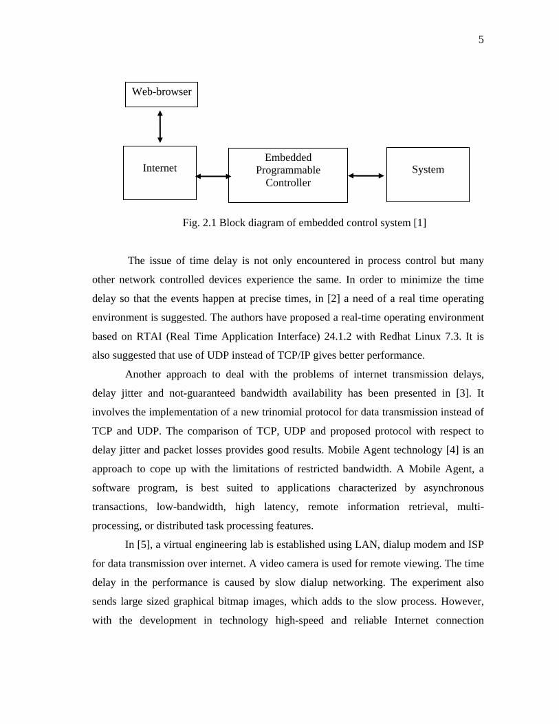
An embedded control system [1] exemplifies a simple web-based control system
which uses programmable controller. It is used to maintain a constant temperature of an
enclosure (Fig. 2.1). The temperature control via internet is a slow process because of
the restricted bandwidth and network time delays. There is a specified time when the
system loop is closed by changing parameters which increase or decrease the
temperature by heating or cooling. So the process control through the Internet should be
applied to those relatively slow processes.
5
Web-browser
Embedded Programmable
Controller
Internet
System
Fig. 2.1 Block diagram of embedded control system [1]
The issue of time delay is not only encountered in process control but many
other network controlled devices experience the same. In order to minimize the time
delay so that the events happen at precise times, in [2] a need of a real time operating
environment is suggested. The authors have proposed a real-time operating environment
based on RTAI (Real Time Application Interface) 24.1.2 with Redhat Linux 7.3. It is
also suggested that use of UDP instead of TCP/IP gives better performance.
Another approach to deal with the problems of internet transmission delays,
delay jitter and not-guaranteed bandwidth availability has been presented in [3]. It
involves the implementation of a new trinomial protocol for data transmission instead of
TCP and UDP. The comparison of TCP, UDP and proposed protocol with respect to
delay jitter and packet losses provides good results. Mobile Agent technology [4] is an
approach to cope up with the limitations of restricted bandwidth. A Mobile Agent, a
software program, is best suited to applications characterized by asynchronous
transactions, low-bandwidth, high latency, remote information retrieval, multi-
processing, or distributed task processing features.
In [5], a virtual engineering lab is established using LAN, dialup modem and ISP
for data transmission over internet. A video camera is used for remote viewing. The time
delay in the performance is caused by slow dialup networking. The experiment also
sends large sized graphical bitmap images, which adds to the slow process. However,
with the development in technology high-speed and reliable Internet connection
6
technologies such as ISDN, cable, and DSL alleviate this problem. In graphical
interfaces, instead of sending a large bitmap of the entire screen a local copy of the
graphical screen can be updated by sending only the required data. This can be
implemented by embedding the code for the remote graphical user interface panels in the
local Web server using Java language applets. The Java applets are automatically sent to
the remote site and are launched by the Web browser. Further, real-time communication
requires only data and status information transfers, substantially improving system
response time.
Researchers have always been in search of better solutions with the development
of technology. In order to, further, solve the problem of transmission of large sized
image file, another concept of Wise-Shop Floor (A Web-based integrated Sensor-driven
e-shop Floor) is presented in [6, 7]. In this approach Java 3D graphics and sensors on the
device are used to view the device virtually. The device can be represented by a scene
graph-based Java-3D model as an applet. The applet remains alive with passing of low
volume sensor data and control commands. It also has the flexibility of visualization by
walk through and fly-around. This concept is implemented to control CNC machine in
[8]. Implementation of Java 3D as compared to other 3D visualizations in [8] is more
appropriate as it does not require any other software to be installed on the client browser.
Internet Telerobotics is emerging field in the decade of web-based control. There
are two generations of internet robotics. Mercury Project (1994) was one of the earliest
outcomes of telerobotics over internet. The first generation was mainly based on direct
control of robotic manipulators and simple mobile robots. These robots have no local
intelligence and they operate in well-structured environment with little uncertainty [9].
In direct control mode the robot behaves as a puppet, and is operated only by the user
who understands the robot’s characteristics. Direct control via the Intemet with inherent
high latency, low bandwidth, uncertain time delay and packet losses, is not suitable for
robotic systems. However, when the robot fails to function and requires remote teaching,
direct control is important [10].
7
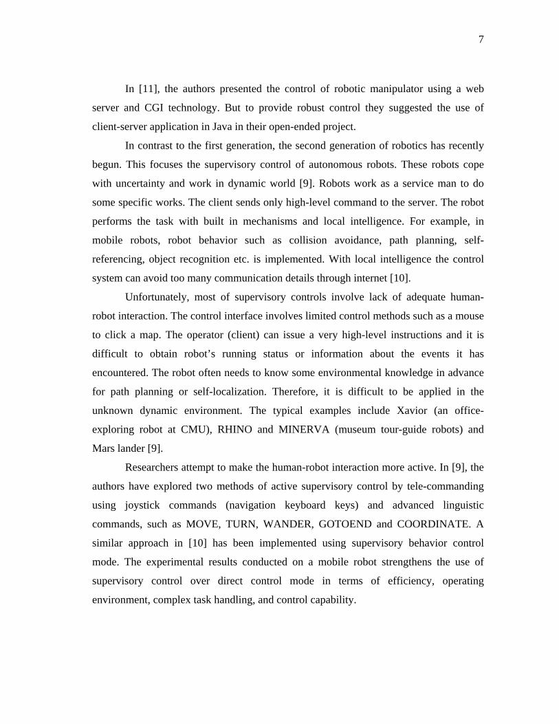
In [11], the authors presented the control of robotic manipulator using a web
server and CGI technology. But to provide robust control they suggested the use of
client-server application in Java in their open-ended project.
In contrast to the first generation, the second generation of robotics has recently
begun. This focuses the supervisory control of autonomous robots. These robots cope
with uncertainty and work in dynamic world [9]. Robots work as a service man to do
some specific works. The client sends only high-level command to the server. The robot
performs the task with built in mechanisms and local intelligence. For example, in
mobile robots, robot behavior such as collision avoidance, path planning, self-
referencing, object recognition etc. is implemented. With local intelligence the control
system can avoid too many communication details through internet [10].
Unfortunately, most of supervisory controls involve lack of adequate human-
robot interaction. The control interface involves limited control methods such as a mouse
to click a map. The operator (client) can issue a very high-level instructions and it is
difficult to obtain robot’s running status or information about the events it has
encountered. The robot often needs to know some environmental knowledge in advance
for path planning or self-localization. Therefore, it is difficult to be applied in the
unknown dynamic environment. The typical examples include Xavior (an office-
exploring robot at CMU), RHINO and MINERVA (museum tour-guide robots) and
Mars lander [9].
Researchers attempt to make the human-robot interaction more active. In [9], the
authors have explored two methods of active supervisory control by tele-commanding
using joystick commands (navigation keyboard keys) and advanced linguistic
commands, such as MOVE, TURN, WANDER, GOTOEND and COORDINATE. A
similar approach in [10] has been implemented using supervisory behavior control
mode. The experimental results conducted on a mobile robot strengthens the use of
supervisory control over direct control mode in terms of efficiency, operating
environment, complex task handling, and control capability.
8
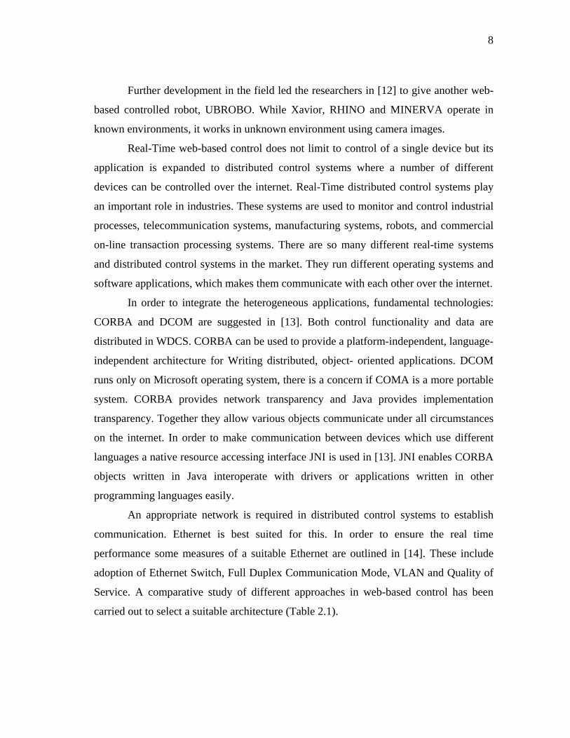
Further development in the field led the researchers in [12] to give another web-
based controlled robot, UBROBO. While Xavior, RHINO and MINERVA operate in
known environments, it works in unknown environment using camera images.
Real-Time web-based control does not limit to control of a single device but its
application is expanded to distributed control systems where a number of different
devices can be controlled over the internet. Real-Time distributed control systems play
an important role in industries. These systems are used to monitor and control industrial
processes, telecommunication systems, manufacturing systems, robots, and commercial
on-line transaction processing systems. There are so many different real-time systems
and distributed control systems in the market. They run different operating systems and
software applications, which makes them communicate with each other over the internet.
In order to integrate the heterogeneous applications, fundamental technologies:
CORBA and DCOM are suggested in [13]. Both control functionality and data are
distributed in WDCS. CORBA can be used to provide a platform-independent, language-
independent architecture for Writing distributed, object- oriented applications. DCOM
runs only on Microsoft operating system, there is a concern if COMA is a more portable
system. CORBA provides network transparency and Java provides implementation
transparency. Together they allow various objects communicate under all circumstances
on the internet. In order to make communication between devices which use different
languages a native resource accessing interface JNI is used in [13]. JNI enables CORBA
objects written in Java interoperate with drivers or applications written in other
programming languages easily.
An appropriate network is required in distributed control systems to establish
communication. Ethernet is best suited for this. In order to ensure the real time
performance some measures of a suitable Ethernet are outlined in [14]. These include
adoption of Ethernet Switch, Full Duplex Communication Mode, VLAN and Quality of
Service. A comparative study of different approaches in web-based control has been
carried out to select a suitable architecture (Table 2.1).
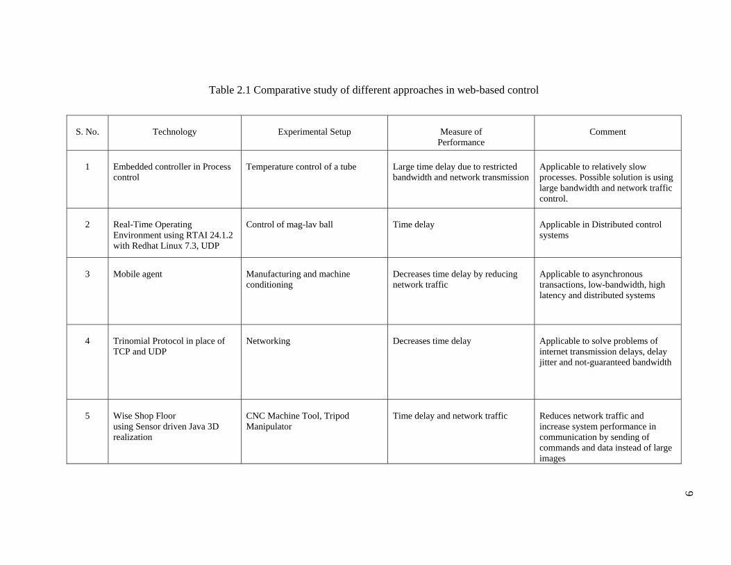
Table 2.1 Comparative study of different approaches in web-based control
S. No.
Technology
Experimental Setup
Measure of
Performance
Comment
1
Embedded controller in Process control
Temperature control of a tube
Large time delay due to restricted bandwidth and network transmission
Applicable to relatively slow processes. Possible solution is using large bandwidth and network traffic control.
2
Real-Time Operating Environment using RTAI 24.1.2 with Redhat Linux 7.3, UDP
Control of mag-lav ball
Time delay
Applicable in Distributed control systems
3
Mobile agent
Manufacturing and machine conditioning
Decreases time delay by reducing network traffic
Applicable to asynchronous transactions, low-bandwidth, high latency and distributed systems
4
Trinomial Protocol in place of TCP and UDP
Networking
Decreases time delay
Applicable to solve problems of internet transmission delays, delay jitter and not-guaranteed bandwidth
5
Wise Shop Floor using Sensor driven Java 3D realization
CNC Machine Tool, Tripod Manipulator
Time delay and network traffic
Reduces network traffic and increase system performance in communication by sending of commands and data instead of large images
9

Table 2.1 continued
S. No.
Technology
Experimental Setup
Measure of
Performance
Comment
6
Control of Adept using LabVIEW, Datasockets, camera and TCP/IP.
Adept manipulator
Real-time viewing performance depends on network bandwidth
7
Ethernet using Full Duplex Communication Mode, VLAN, embedded server.
Distributed Control System
Real-Time Performance, Network Traffic
Full bandwidth available to all equipments due to switch, so reduces network traffic
8
CORBA and COM
Distributed Control System
Real-Time Performance, Network Transparency
To provide a platform-independent, language-independent architecture
9
Space Browser: Internet and wireless transmission, camera, microphone, speaker
A flying space browser (tele-mobot)
Real-time performance of object detection and avoidance.
10
Robotic manipulator (Web-server and CGI, Java and Web-cam )
Control of Autonomous Robots
Robust control using all the system architecture in Java
11
Multi-sensor based control of Autonomous Robots. CGI for wireless transmission and Fuzzy-logic for navigation algorithm.
Three-wheeled mobile robot with 20 tactile and 16 sonar sensors, CCD Camera, wireless communication,
Efficiency, operating environment, complex task handling and control capability
Behavior control superior to direct control
10
11
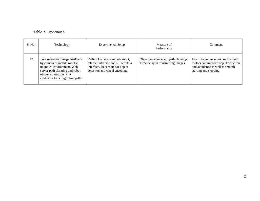
Table 2.1 continued
S. No.
Technology
Experimental Setup
Measure of
Performance
Comment
12
Java server and image feedback by camera of mobile robot in unknown environment. Web-server path planning and robot obstacle detection. PID controller for straight line path.
Ceiling Camera, a remote robot, internet interface and RF wireless interface, IR sensors for object detection and wheel encoding,
Object avoidance and path planning. Time delay in transmitting images.
Use of better encoders, sensors and motors can improve object detection and avoidance as well as smooth starting and stopping.

12
Summary of literature review
Web-based control has been discussed with respect to time delay. Low bandwidth and
network traffic are the main sources of time delay. Researchers have devised methods of
reducing time delays. Trinomial protocol and mobile agent are software specific
programs. They aid in increasing the network speed thereby reducing the network traffic
and hence time delay. Sending data over the Internet in place of images further reduces
traffic. Wise shop floor implements the communication using sensor driven data and
Java3D technology.
Virtual engineering lab experiment uses Labview, datasockets, camera and dialup
connection. The dialup connection introduces time delay. Another experiment on robotic
manipulator uses web-cam and cgi script on server to capture the images and transmit
them on internet. The webcam images are sent from the server along with other data. It
increases the traffic and hence time delay. In supervisory control of autonomous robots,
the server has local intelligence of robots. The client sends the high level commands
using joy-stick.
This study implemented an architecture aimed at reducing time delay. The
interaction of user with the setup takes place through a graphic user interface, which is a
web-page comprised of graphics and commands. After the web-page is accessed, further
communication takes place by data, not images, which reduces network traffic. The
camera transmitted data separately over the Internet, further reduces the congestion
because the camera images do not need to travel from the server. For real time
communication between the client and the Gantry Mechanism, the server runs
executable files written in Common Gateway Interface (CGI), which is best suited in
processing the HTML forms. Finally a high speed internet connection was used.
Selection of software and hardware for control over Internet
In this problem the communication line comprises of three nodes. These are client,
server and working object. The client side interaction is accomplished using a GUI
13
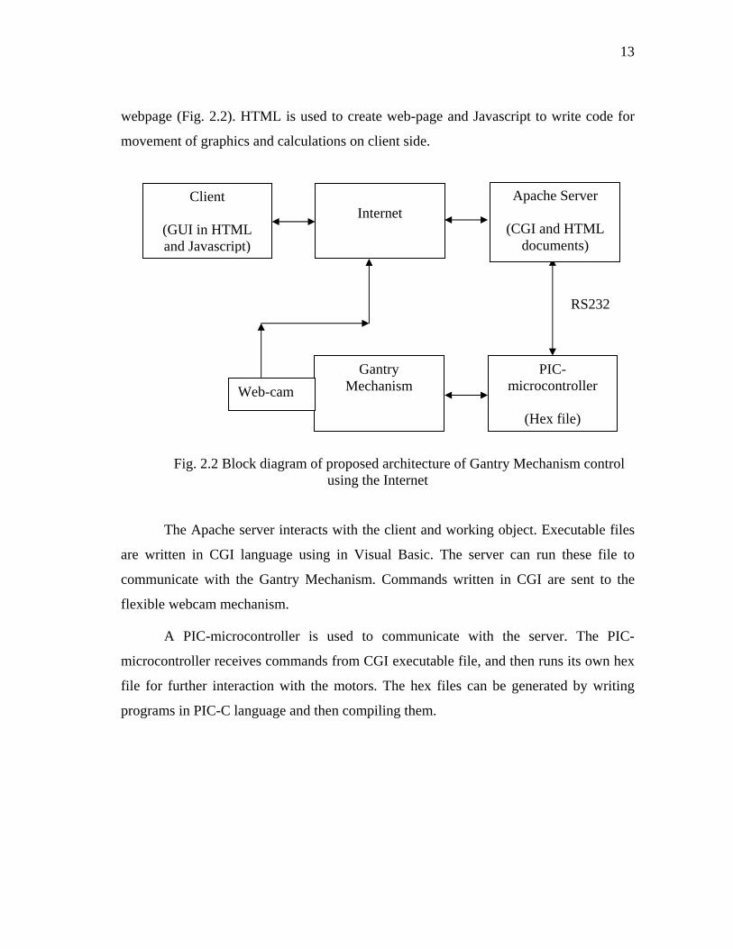
webpage (Fig. 2.2). HTML is used to create web-page and Javascript to write code for
movement of graphics and calculations on client side.
RS232
Client
(GUI in HTML and Javascript)
PIC-microcontroller
(Hex file)
Gantry Mechanism Web-cam
Apache Server
(CGI and HTML documents)
Internet
Fig. 2.2 Block diagram of proposed architecture of Gantry Mechanism control using the Internet
The Apache server interacts with the client and working object. Executable files
are written in CGI language using in Visual Basic. The server can run these file to
communicate with the Gantry Mechanism. Commands written in CGI are sent to the
flexible webcam mechanism.
A PIC-microcontroller is used to communicate with the server. The PIC-
microcontroller receives commands from CGI executable file, and then runs its own hex
file for further interaction with the motors. The hex files can be generated by writing
programs in PIC-C language and then compiling them.
14
Selection of mechanism
Working space of SCARA robot
The Adept manipulator has four degrees of freedom upto the end-effecter. Three are
rotational in the X-Y plane and the fourth is translational along the z-axis. The rotational
motion covers a radius of 800mm, and the vertical stroke is of length 203 mm (approx).
The working table has dimensions of 1235 x 1835. A border of 300 mm is kept to
accommodate the mechanism and the working space. The following is considered to
calculate the maneuvering space of mechanism:
a) The vertical distance between the top of table and the base of robot stroke is 400
mm. The stroke length is 203 mm. Therefore, the z-axis movement of mechanism can be
between 203 and 400mm to view the end-effecter and the object.
b) The robot has a working radius of 800mm. The mechanism can enter this space
based on figuring out available space using sensor feedback. However, the web-cam can
be held in the border area around the table because in this area it can give good quality
of image as well as viewing envelope.
c) Incorporation of a rotational motion of the camera will let the user view the space at
a point without moving it to another point.
Proposed Mechanisms
In order to satisfy the requirement of maneuvering the camera in space around
the SCARA robot, two mechanisms are studied.
a) Gantry Mechanism: In this mechanism three translational motions along X, Y and Z-
axis, and one rotational motion in X-Y plane at the end of mechanism will suffice the
requirement of viewing the workspace (Fig. 1.1).
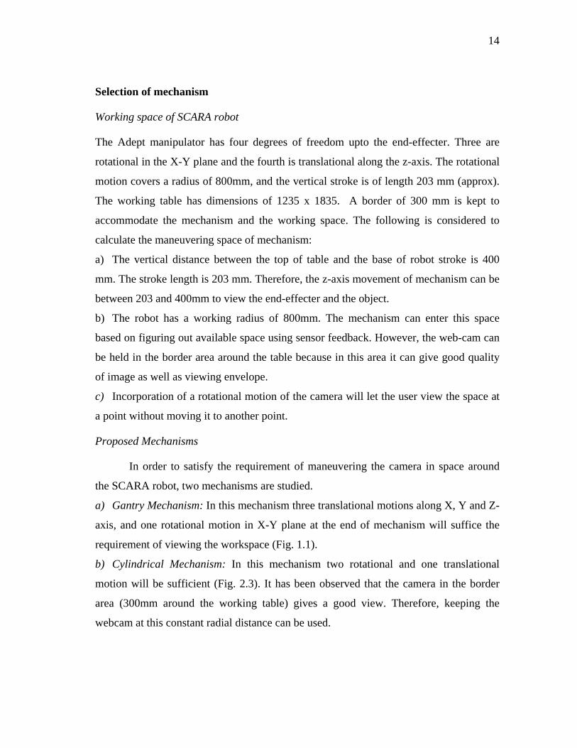
b) Cylindrical Mechanism: In this mechanism two rotational and one translational
motion will be sufficient (Fig. 2.3). It has been observed that the camera in the border
area (300mm around the working table) gives a good view. Therefore, keeping the
webcam at this constant radial distance can be used.
15
Comparison of Gantry Mechanism and Cylindrical Mechanism
A comparative study is performed in order to select the suitable mechanism. The
comparison is based on certain requirements and parameters (Table-2.2).
a. The Gantry Mechanism has four degrees of freedom, while the Cylindrical
Mechanism has three degrees of freedoms. The Cylindrical Mechanism is less flexible
than the Gantry Mechanism. Number of components of the Gantry Mechanism, such as
motors, shafts and sensors, will be more than the Cylindrical Mechanism.
b. The Gantry Mechanism is more rigid in case of motion in the X and Y direction.
c. The Cylindrical mechanism has to be rotated around the center point, which will be
anchored at the ceiling. This requires thrust bearing of high capacity for θ rotation.
d. There are more variables of control in case of the Gantry Mechanism because it has
more degrees of freedom.
e. The Gantry Mechanism covers more working space because there is no restriction on
radial movement as in case of the Cylindrical Mechanism.
Rotation (α)
Web-cam
Translational (z)
Ceiling
Rotation (θ)
Fig.-2.3 Cylindrical Mechanism
16
The analysis of different parameters (Table 2.2) leads to the selection of the
Gantry Mechanism for this application. It has more rigidity because of four supports
while cylindrical mechanism is supported at the center. More rigid structure leads to less
vibration problems and camera can be moved precisely to the specified location. The
Gantry mechanism has four degrees of freedom, which makes it more flexible, and also
enables it to cover more working space. The following chapters discuss the design,
implementation, control and evaluation of performance of the Gantry mechanism.
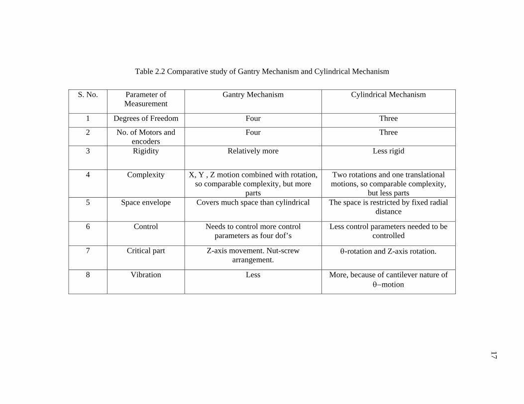
S. No. Parameter of Measurement
Gantry Mechanism Cylindrical Mechanism
1 Degrees of Freedom Four Three
2 No. of Motors and encoders
Four Three
3 Rigidity Relatively more Less rigid
4 Complexity X, Y , Z motion combined with rotation, so comparable complexity, but more
parts
Two rotations and one translational motions, so comparable complexity,
but less parts 5 Space envelope Covers much space than cylindrical The space is restricted by fixed radial
distance
6 Control Needs to control more control parameters as four dof’s
Less control parameters needed to be controlled
7 Critical part
Z-axis movement. Nut-screw arrangement.
θ-rotation and Z-axis rotation.
8 Vibration Less More, because of cantilever nature of θ−motion
17
Table 2.2 Comparative study of Gantry Mechanism and Cylindrical Mechanism

18
CHAPTER III
DESIGN OF GANTRY MECHANISM
Introduction
The basis of design of the Gantry mechanism is the gantry robot, also known as a
Cartesian robot. A gantry robot contains a minimum of three elements of motion, each of
which represents a linear motion in a single direction. These motions are arranged to be
perpendicular to each other and are typically labeled X, Y, and Z. X and Y are located in
the horizontal plane and Z is vertical. The interior of this box is referred to as the
working envelope, the space in which the robot can move things anywhere.
The Gantry Mechanism designed, in this thesis, has one more degree of freedom,
which is rotation in the X-Y plane. The fourth degree of freedom enables the user to
horizontally observe the workspace by rotating the end-effecter.
Design and selection of mechanical parts
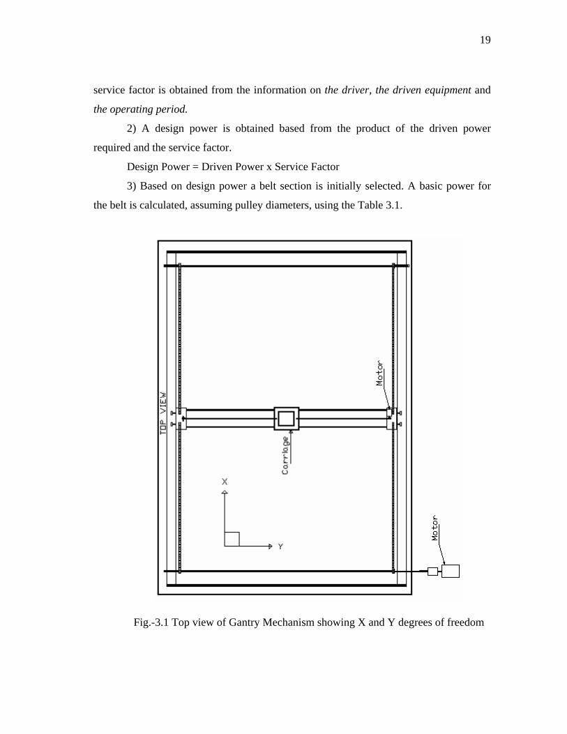
The motion in X and Y direction is achieved by power transmission through timing belts
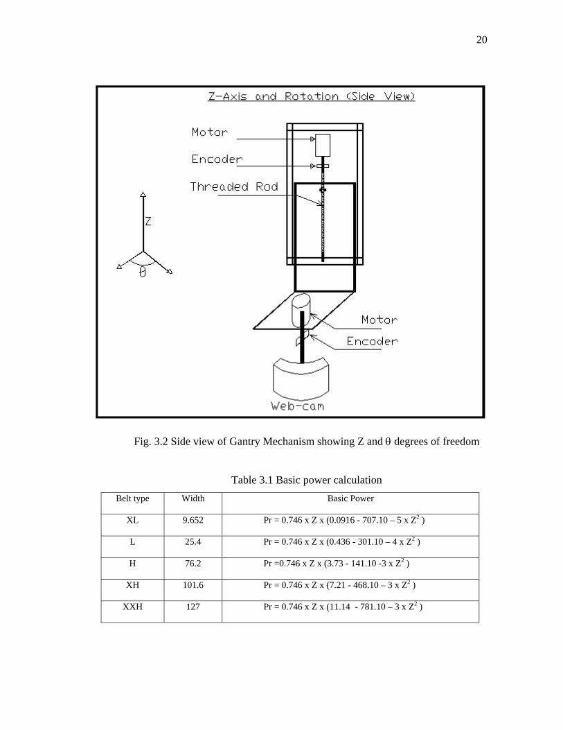
and pulleys assemblies (Fig. 3.1), while Z-direction motion comprise of a threaded rod
and nut arrangement (Fig. 3.2). The motor for θ-direction motion directly couples with a
shaft, the other end of which carries the camera.
Timing belts and pulleys
Timing belts and pulleys provide synchronized motion. The grooves of timing
belts mate with the teeth on the timing pulleys, which make the drive positive. The slip
between the belt and the pulley is extremely minor, which ensures that the driven pulley
is always rotating at a fixed speed ratio to the driving pulley. These belts have an
operating efficiency of about 98% and they can operate successfully between 8000 and
12000 hrs.
Belt design procedure, based on power calculations, has following steps [16]:
1) The required driven power is calculated from the driven speed and the
maximum driven torque required (including inertia load, shock loads, friction, etc). A
19
service factor is obtained from the information on the driver, the driven equipment and
the operating period.
2) A design power is obtained based from the product of the driven power
required and the service factor.
Design Power = Driven Power x Service Factor
3) Based on design power a belt section is initially selected. A basic power for
the belt is calculated, assuming pulley diameters, using the Table 3.1.
Fig.-3.1 Top view of Gantry Mechanism showing X and Y degrees of freedom
20
Fig. 3.2 Side view of Gantry Mechanism showing Z and θ degrees of freedom
Table 3.1 Basic power calculation Belt type Width Basic Power
XL 9.652 Pr = 0.746 x Z x (0.0916 - 707.10 – 5 x Z2 )
L 25.4 Pr = 0.746 x Z x (0.436 - 301.10 – 4 x Z2 )
H 76.2 Pr =0.746 x Z x (3.73 - 141.10 -3 x Z2 )
XH 101.6 Pr = 0.746 x Z x (7.21 - 468.10 – 3 x Z2 )
XXH 127 Pr = 0.746 x Z x (11.14 - 781.10 – 3 x Z2 )
21
The design and selection of parts has been performed starting from θ-motion.
Subsequently, calculations for Z-motion, Y-motion and X-motion are made. A specimen
calculation is presented in Appendix-A. The inputs and results are shown in Table 3.2.
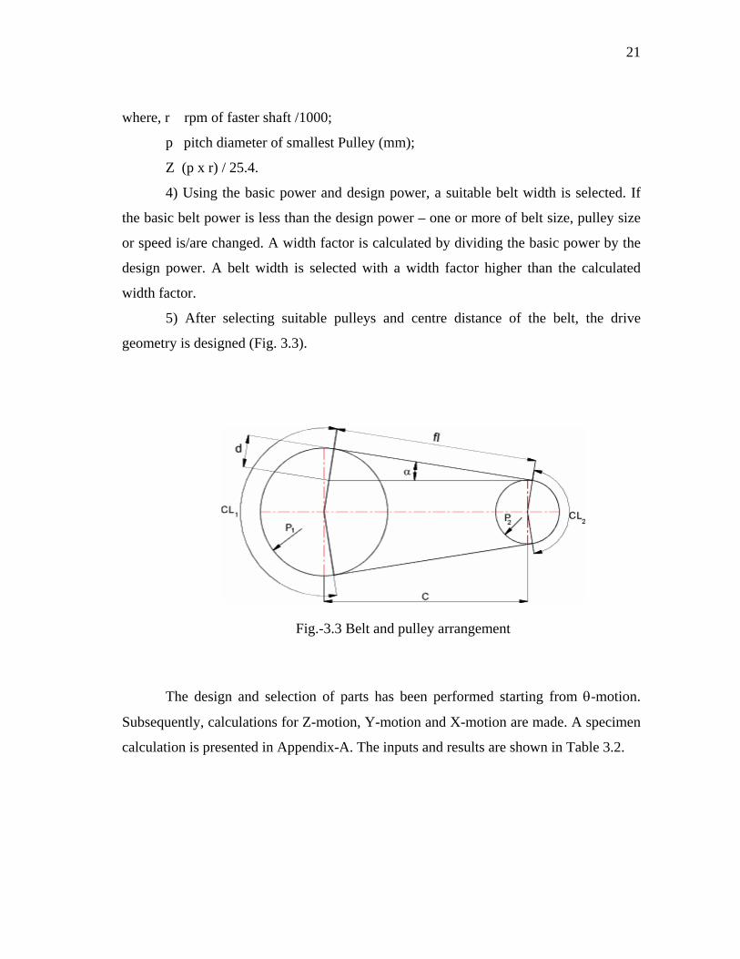
5) After selecting suitable pulleys and centre distance of the belt, the drive
geometry is designed (Fig. 3.3).
4) Using the basic power and design power, a suitable belt width is selected. If
the basic belt power is less than the design power – one or more of belt size, pulley size
or speed is/are changed. A width factor is calculated by dividing the basic power by the
design power. A belt width is selected with a width factor higher than the calculated
width factor.
where, r rpm of faster shaft /1000;
Z (p x r) / 25.4.
p pitch diameter of smallest Pulley (mm);
Fig.-3.3 Belt and pulley arrangement

22
Table 3.2 Calculation of timing belts and pulleys dimensions
Inputs Results Selection
Linear
Velocity (mm/s)
Pulley Dia. (assumed)
(mm)
Load (mass kg)
Factor of safety
Pdesign (kW)
PBasic (kW)
Width factor
Belt Width (mm)
Pulley PCD (mm)
Pitch (Belt and Pulley,
mm)
X-Motion 100 20 2 2 1.43 x 10⁻³ 5.13 x 10⁻³ 3.58 9.5 16.2 5.08
Y-Motion 100 20 1.5 2 0.0124 0.0051 415 9.5 16.2 5.08
23
Shafts
Shafts for X-direction motion
The shafts, which transmit power in the X-direction, are designed for torsional
loading. Diameter of a shaft in torsion is given by the following relation:
100016 31
xTd ⎥⎦⎤
⎢⎣⎡=
πτ…………………………..………………………… (3.1)
where, d = diameter of shaft (mm);
T = Torque (0.1197Nm, Appendix-C2);
τ = Allowable shear stress;
= 260Mpa (Maximum Shear Stress Theory, τall = 0.5Sy, Sy = 520 MPa);
d = (16 x 0.1197 / (pi x 260 x 106))(1/3)x1000;
= 1.3285 mm;
Selected shaft dia = 6 mm.
Shafts for Y-direction motion
The shafts for Y-direction undergo bending due to the sliding assembly for Z and θ-
motion. Diameter of a shaft in bending is given by the following relation:
100032 31
xMd ⎥⎦⎤
⎢⎣⎡=
πσ……………………….…..……………………… (3.2)
where, d = diameter of shaft (mm);
M = Bending Moment (Nm);
σ = Allowable bending stress;
= 260Mpa (Maximum Normal Stress Theory and Von Mises Theory, σall = Sut,
Sut = 860 MPa);
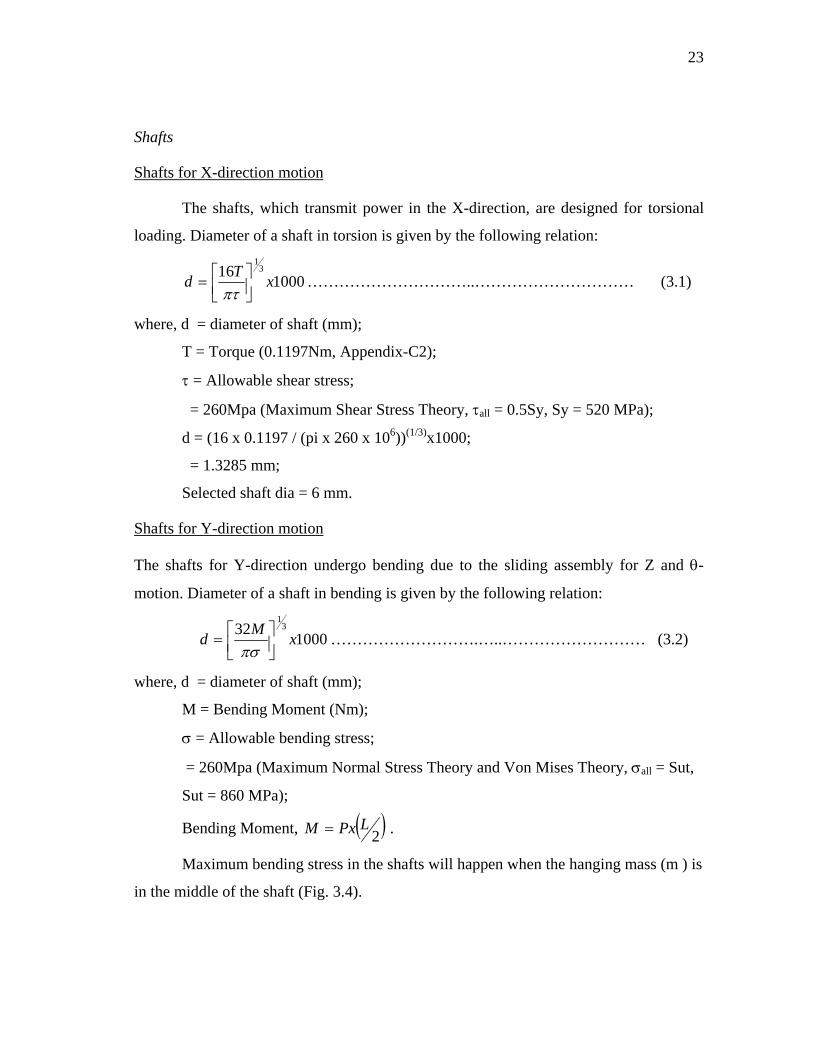
Bending Moment, ( )2LPxM = .
Maximum bending stress in the shafts will happen when the hanging mass (m ) is
in the middle of the shaft (Fig. 3.4).
24
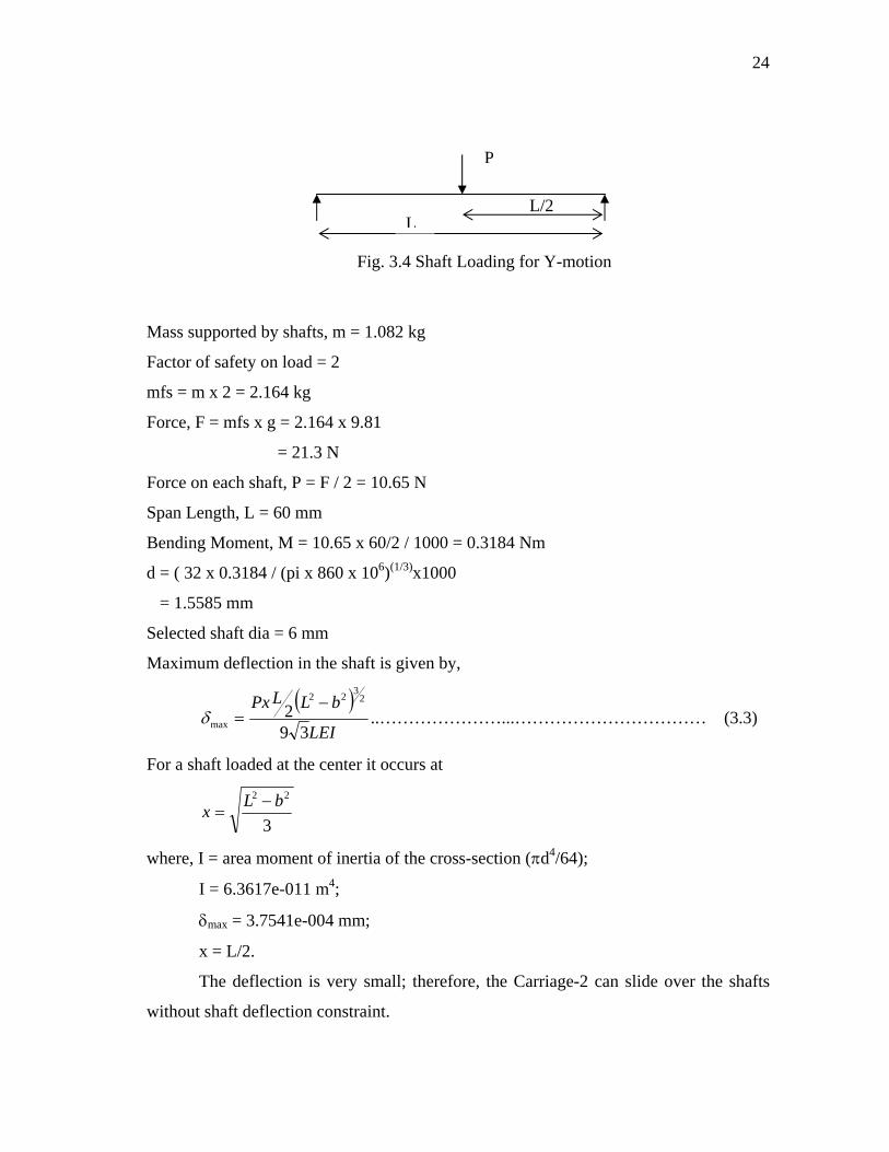
L/2 L
P
Fig. 3.4 Shaft Loading for Y-motion
Mass supported by shafts, m = 1.082 kg
Factor of safety on load = 2
mfs = m x 2 = 2.164 kg
Force, F = mfs x g = 2.164 x 9.81
= 21.3 N
Force on each shaft, P = F / 2 = 10.65 N
Span Length, L = 60 mm
Bending Moment, M = 10.65 x 60/2 / 1000 = 0.3184 Nm
d = ( 32 x 0.3184 / (pi x 860 x 106)(1/3)x1000
= 1.5585 mm
Selected shaft dia = 6 mm
Maximum deflection in the shaft is given by,
( )LEI
bLLPx
392
2322
max
−=δ ..…………………...…………………………… (3.3)
For a shaft loaded at the center it occurs at
3
22 bLx −=
where, I = area moment of inertia of the cross-section (πd4/64);
I = 6.3617e-011 m4;
δmax = 3.7541e-004 mm;
x = L/2.
The deflection is very small; therefore, the Carriage-2 can slide over the shafts
without shaft deflection constraint.
25
Shafts for θ-direction motion
The shaft for the θ-direction is also designed for torsional loading. Diameter of a
shaft in torsion is given by the relation 3.1.
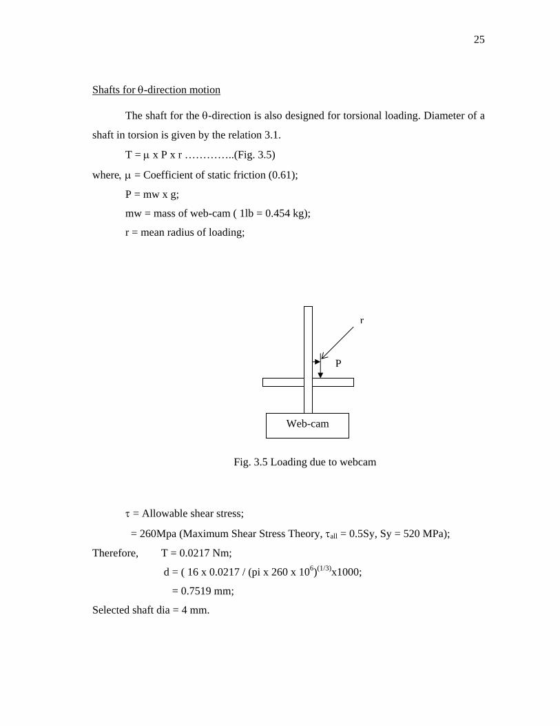
T = μ x P x r …………..(Fig. 3.5)
where, μ = Coefficient of static friction (0.61);
P = mw x g;
mw = mass of web-cam ( 1lb = 0.454 kg);
r = mean radius of loading;
Web-cam
P
r
Fig. 3.5 Loading due to webcam
τ = Allowable shear stress;
= 260Mpa (Maximum Shear Stress Theory, τall = 0.5Sy, Sy = 520 MPa);
Therefore, T = 0.0217 Nm;
d = ( 16 x 0.0217 / (pi x 260 x 106)(1/3)x1000;
= 0.7519 mm;
Selected shaft dia = 4 mm.

26
Threaded rod and nuts
The threaded rod and hex nuts of thread size 5/16 – 24 are selected. Pitch of
threads is 24 threads per inch.
Design and selection of electrical parts
DC motors
Power required to drive a DC motor is the product of current and voltage. This power is
transmitted through a motor-gearbox assembly to the body to be moved. The gearbox
reduces the speed and increases the torque at its output shaft. The torque generated by a
motor is directly proportional to the current passing through it.
Mo = kM x I ------------------------------------------- (3.4)
where, Mo = Torque produced;
kM = torque constant;
I = current.
A constant current produces a constant torque regardless of voltage. Input
voltage is given by
V = R x I + kw x n ----------------------------------------- (3.5)
where, V = input voltage;
kw = speed constant;
I = current;
R = resistance of winding;
n = motor shaft speed.
At constant voltage output speed and torque are inversely proportional. Increasing the
load torque decreases the speed and vice-versa (Fig. 3.6).
τ = τs – (τs / ωn) ω −−−−−−−−−−−−−−−−−−−−−−− (3.6)
ω = (τs – τ) ωn/ τs −−−−−−−−−−−−−−−−−−−−−−− (3.7)
where, τ = motor torque;
ω = motor speed;
τs = stall torque (no-load torque);

27
ωn = no-load speed.
ωn Slope = τs / ωn
τs
Fig. 3.6 Torque vs speed of motor
τ
ω
Output power (P) is given by
P = τ x ω −−−−−−−−−−−−−−−−−−−−−− (3.8)
P = (τs – (τs / ωn) ω) ω −−−−−−−−−−−−−−−−−−−−−− (3.9)
P = τ ((τs – τ) ωn/ ω) −−−−−−−−−−−−−−−−−−−−−− (3.10)
On differentiating equation (3.9) or (3.10) with respect to ω or τ and equating the result
to zero determines the operating point. On substitution of this operating point in equation
(3.8) gives maximum power (Pmax)
Pmax = (1/4) τs ωn --------------------------------------- (3.11)
The operating point of maximum output power is at half of stall torque and half of no-
load speed. Due to thermal consideration, the motor is operated at the maximum power.
The most efficient area of motor is to operate 90% of no-load speed and 10-30% of stall
torque. For use with gearbox a motor is operated at less operating voltage than the
nominal voltage rating. This results in lower noise generation and better life
characteristics.

28
The selection procedure involves the following steps:
1. Required torque (τ) and speed (ω) are calculated based on the system
requirements. Power required is the product of required torque and speed.
2. Design power (PDES) is calculated by multiplying the power required with factor
of safety. A motor of higher power rating than the design power, is selected.
3. Speed (nA) at available voltage (VA) is calculated using no-load speed (nL) and
nominal voltage (V).
nA = nI x (VA/V) --------------------------------------- (3.12)
4. Maximum power (PMAX) is the determined from speed (nA) and stall torque (τs)
Operating speed (no) is assumed greater than 50% of no-load speed.
5. Gear ratio is calculated using operating speed and speed required at output of
gearbox. Using gear ratio and load torque (τL) equivalent torque (τE) at the motor
is also calculated.
6. Equivalent load current (ΙE) is calculated using kM and equivalent torque (τE).
7. Current required (IR) is the sum of equivalent load current (IE) and no load
current (Io)
IR = IE + Io --------------------------------------- (3.13)
8. The actual speed, at load, is calculated using,
n = nA – (IR x R) / kM --------------------------------------- (3.14)
9. Power and torque requirements are checked using the following relations:
PMAX > PDES
τS > τE
10. If the requirements of step 9 are not satisfied then a motor of higher power rating
is selected, and calculations of steps 1 through 9 are performed again.
For the Gantry Mechanism four motors have been selected (Table 3.3). An example
calculation is presented in Appendix B.

29
Table 3.3 Selection of motors and gearheads
Required parameters Selected Motor
Design Power (W)
Torque (Nm)
Speed (rpm)
Power (W)
No load speed (rpm)
Stall Torque (mNm)
Gearhead Reduction
Speed at Gearhead
(rpm)
Torque at Gearhead
(Nm) X-
Motion 3.3 0.1066 118 4.0 11500 14.4 104 : 1 110 1.4976
Y-Motion 1 0.376 100 2.5 11400 8.5 76 : 1 150 0.646
Z-Motion 1 0.094 100 2.5 11400 8.5 76 : 1 150 0.646
θ-Motion 0.15 0.0194 30 0.75 13000 1.25 256 : 1 50 0.320
30
Sensors
Optical encoders feed back the position signals and angle signals from the output shafts
to the PIC microcontroller. For θ-motion, one optical encoder of bore size of 4mm, and
for X, Y and Z motion, three optical encoders of bore size 6mm, are selected.
H-Bridge motor controller
The motors require bi-directional motion control to execute motion in the
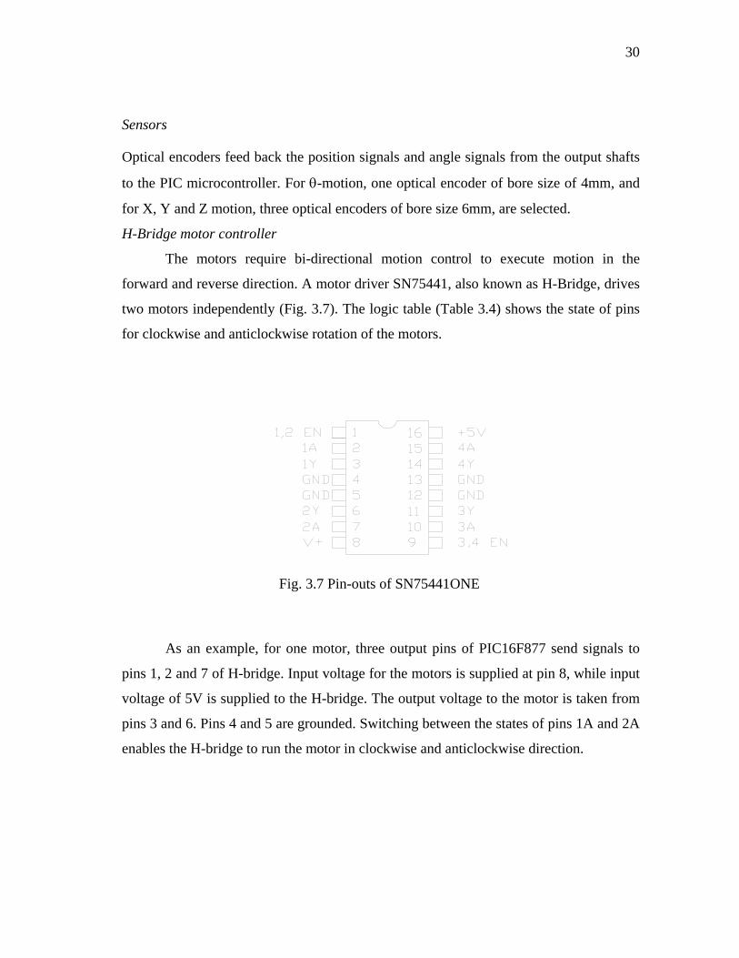
forward and reverse direction. A motor driver SN75441, also known as H-Bridge, drives
two motors independently (Fig. 3.7). The logic table (Table 3.4) shows the state of pins
for clockwise and anticlockwise rotation of the motors.
Fig. 3.7 Pin-outs of SN75441ONE
As an example, for one motor, three output pins of PIC16F877 send signals to
pins 1, 2 and 7 of H-bridge. Input voltage for the motors is supplied at pin 8, while input
voltage of 5V is supplied to the H-bridge. The output voltage to the motor is taken from
pins 3 and 6. Pins 4 and 5 are grounded. Switching between the states of pins 1A and 2A
enables the H-bridge to run the motor in clockwise and anticlockwise direction.
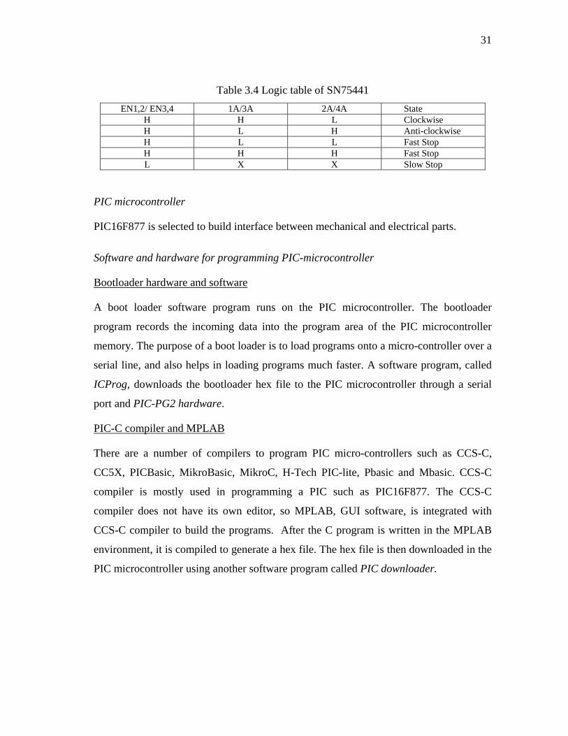
31
Table 3.4 Logic table of SN75441 EN1,2/ EN3,4 1A/3A 2A/4A State
H H L Clockwise H L H Anti-clockwise H L L Fast Stop H H H Fast Stop L X X Slow Stop
PIC microcontroller
PIC16F877 is selected to build interface between mechanical and electrical parts.
Software and hardware for programming PIC-microcontroller
Bootloader hardware and software
A boot loader software program runs on the PIC microcontroller. The bootloader
program records the incoming data into the program area of the PIC microcontroller
memory. The purpose of a boot loader is to load programs onto a micro-controller over a
serial line, and also helps in loading programs much faster. A software program, called
ICProg, downloads the bootloader hex file to the PIC microcontroller through a serial
port and PIC-PG2 hardware.
PIC-C compiler and MPLAB
There are a number of compilers to program PIC micro-controllers such as CCS-C,
CC5X, PICBasic, MikroBasic, MikroC, H-Tech PIC-lite, Pbasic and Mbasic. CCS-C
compiler is mostly used in programming a PIC such as PIC16F877. The CCS-C
compiler does not have its own editor, so MPLAB, GUI software, is integrated with
CCS-C compiler to build the programs. After the C program is written in the MPLAB
environment, it is compiled to generate a hex file. The hex file is then downloaded in the
PIC microcontroller using another software program called PIC downloader.
32
CHAPTER IV
CONTROL OF GANTRY MECHANISM
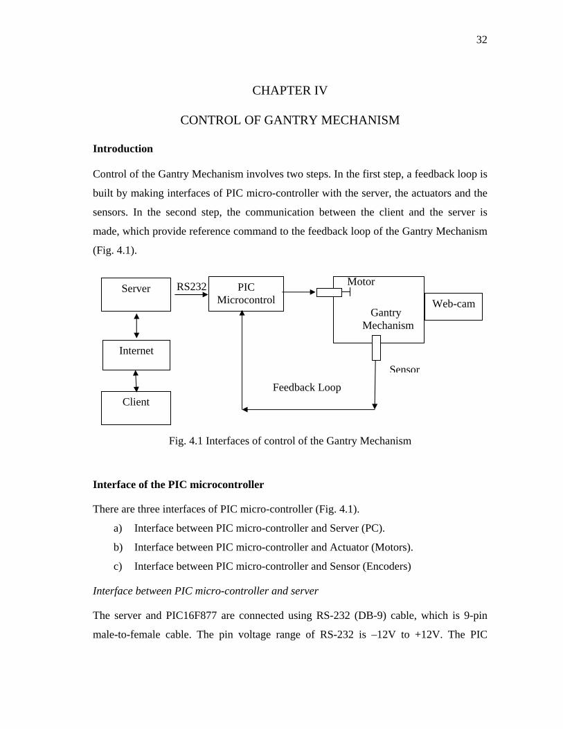
Introduction
Control of the Gantry Mechanism involves two steps. In the first step, a feedback loop is
built by making interfaces of PIC micro-controller with the server, the actuators and the
sensors. In the second step, the communication between the client and the server is
made, which provide reference command to the feedback loop of the Gantry Mechanism
(Fig. 4.1).
Web-cam
Sensor
Gantry Mechanism
Server RS232 PIC Microcontrol
Motor
Internet
Client Feedback Loop
Fig. 4.1 Interfaces of control of the Gantry Mechanism
Interface of the PIC microcontroller
There are three interfaces of PIC micro-controller (Fig. 4.1).
a) Interface between PIC micro-controller and Server (PC).
b) Interface between PIC micro-controller and Actuator (Motors).
c) Interface between PIC micro-controller and Sensor (Encoders)
Interface between PIC micro-controller and server
The server and PIC16F877 are connected using RS-232 (DB-9) cable, which is 9-pin
male-to-female cable. The pin voltage range of RS-232 is –12V to +12V. The PIC
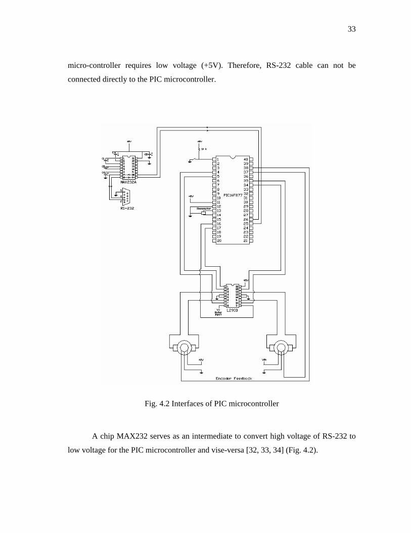
33
micro-controller requires low voltage (+5V). Therefore, RS-232 cable can not be
connected directly to the PIC microcontroller.
Fig. 4.2 Interfaces of PIC microcontroller
A chip MAX232 serves as an intermediate to convert high voltage of RS-232 to
low voltage for the PIC microcontroller and vise-versa [32, 33, 34] (Fig. 4.2).
34
Interface between PIC micro-controller and actuators
PIC micro-controller pins provide low currents (20mA), which is not sufficient to meet
the output torque requirement of motor. H-Bridge chip is used to drive the motors at
high currents as well as bi-directional motion control.
Interface between PIC micro-controller and sensors
Optical encoders are used to measure the actual positions of the Gantry Mechanism. The
optical disc of the sensor is mounted on the output shaft. When the disc rotates along
with the shaft, the sensor produces pulses of high and low voltages at the output channel.
These pulses are counted to determine the actual speed and the position of the shaft (Fig.
4.2).
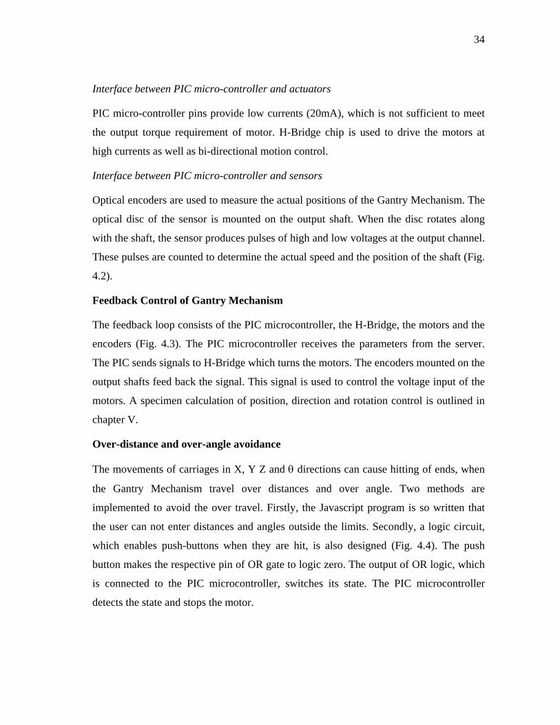
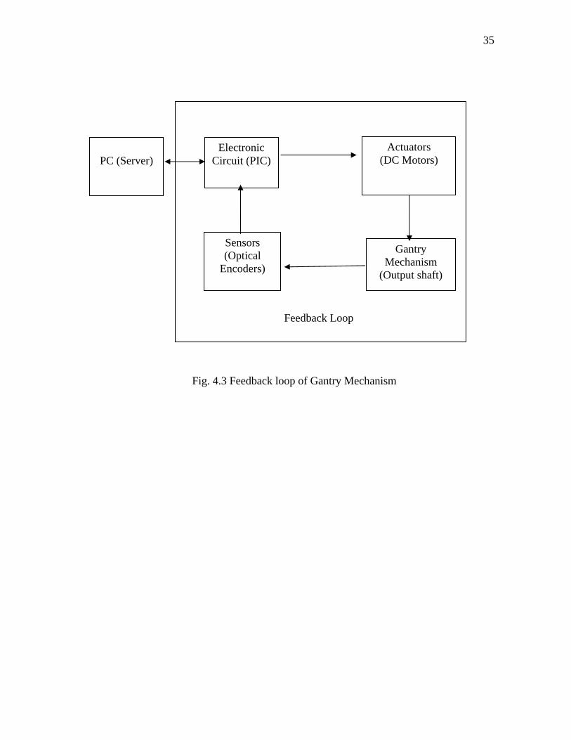
Feedback Control of Gantry Mechanism
The feedback loop consists of the PIC microcontroller, the H-Bridge, the motors and the
encoders (Fig. 4.3). The PIC microcontroller receives the parameters from the server.
The PIC sends signals to H-Bridge which turns the motors. The encoders mounted on the
output shafts feed back the signal. This signal is used to control the voltage input of the
motors. A specimen calculation of position, direction and rotation control is outlined in
chapter V.
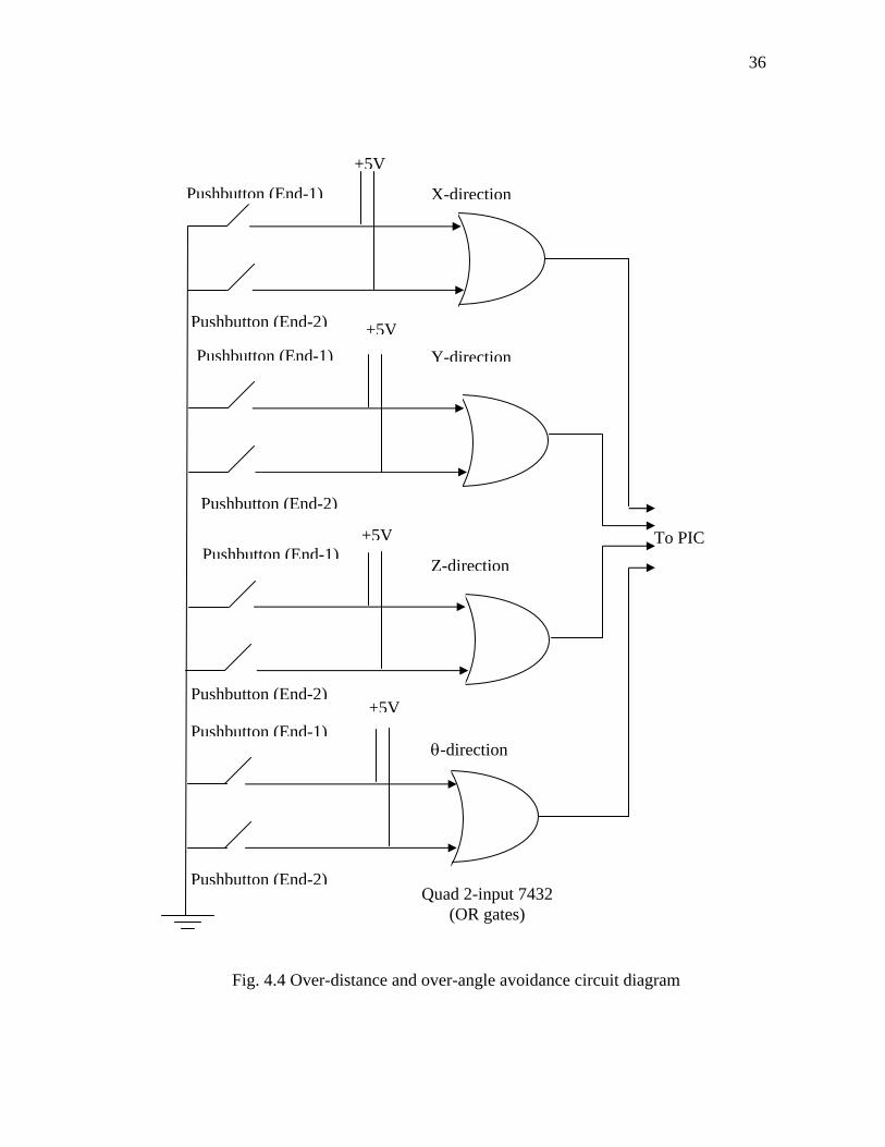
Over-distance and over-angle avoidance
The movements of carriages in X, Y Z and θ directions can cause hitting of ends, when
the Gantry Mechanism travel over distances and over angle. Two methods are
implemented to avoid the over travel. Firstly, the Javascript program is so written that
the user can not enter distances and angles outside the limits. Secondly, a logic circuit,
which enables push-buttons when they are hit, is also designed (Fig. 4.4). The push
button makes the respective pin of OR gate to logic zero. The output of OR logic, which
is connected to the PIC microcontroller, switches its state. The PIC microcontroller
detects the state and stops the motor.
35
Feedback Loop
Actuators (DC Motors)
Gantry Mechanism
(Output shaft)
Sensors (Optical
Encoders)
Electronic Circuit (PIC)
PC (Server)
Fig. 4.3 Feedback loop of Gantry Mechanism
36
To PIC
Pushbutton (End-1)
Pushbutton (End-2)
X-direction
+5V
+5V
Pushbutton (End-1)
Pushbutton (End-2)
Y-direction
+5VPushbutton (End-1)
Pushbutton (End-2)
Z-direction
Pushbutton (End-1)
Pushbutton (End-2)
θ-direction
Quad 2-input 7432 (OR gates)
+5VPushbutton (End-2)
Fig. 4.4 Over-distance and over-angle avoidance circuit diagram

37
Control of the Gantry Mechanism over the Internet
The user sends commands to the server over the internet. The server processes these
commands and prepares the commands for the PIC microcontroller. The various
programming languages used to develop programs and interfaces are shown in Fig. 4.5.
PIC microcontroller
(PIC-C)
Server
(CGI, Visual Basic)
Client
(HTML and Javascript)
Fig. 4.5 Programming software of client, server and PIC-microcontroller
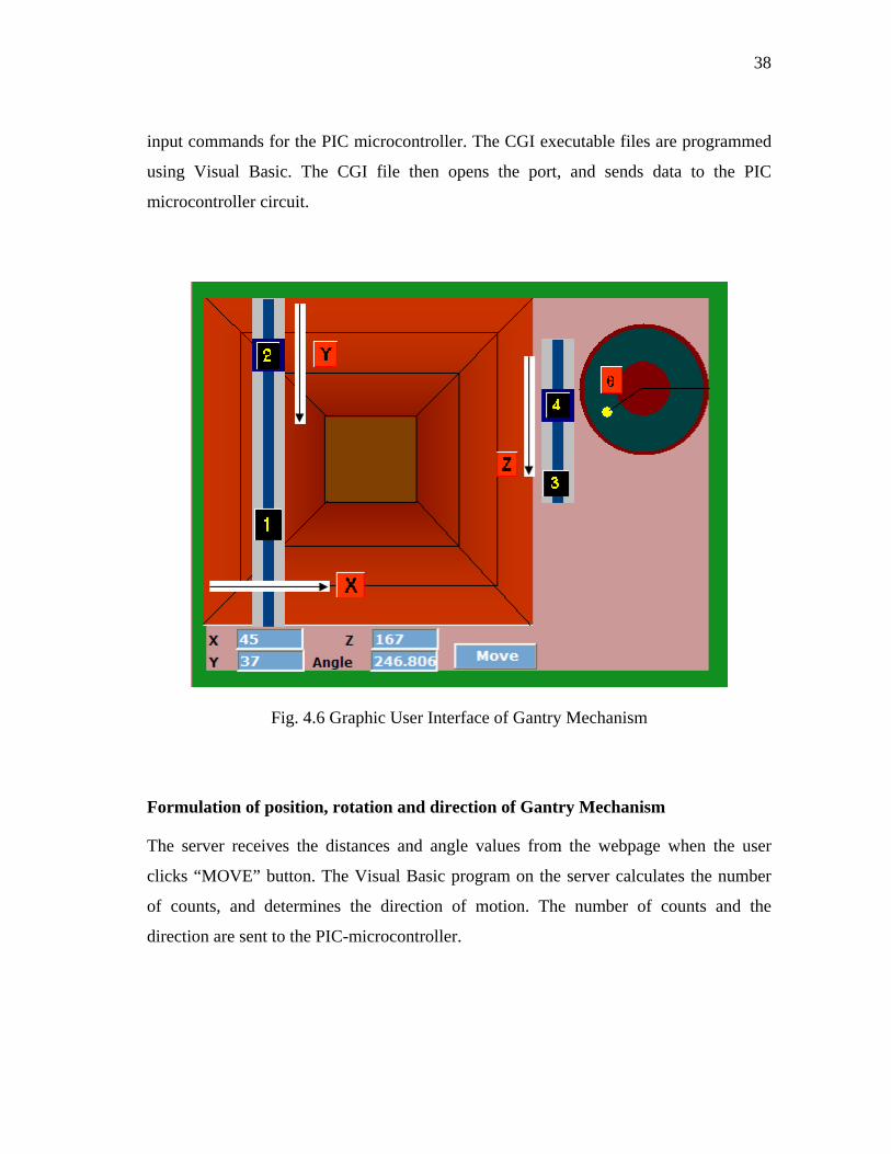
Design of web-page
A Graphic User Interface is designed to make interaction between the user and the web-
browser. The user selects the coordinates of the Gantry Mechanism either moving the
sliders of GUI using a computer mouse, or entering numeric data in the text boxes using
a computer keyboard (Fig. 4.6). The graphic images are drawn in Microsoft Paint.
Dynamic HTML, HTML and Javascript language, code is written to control the
movement of sliders. The slider-1 moves in X-direction, and the carriage-2 slides over
the slider-1 and makes Y-direction motion. The carriage4 slides over slider-3 and makes
motion in Z-direction. Rotation in θ-direction is achieved by rotating the yellow circular
slider inside the green area.
Server-PIC interface programming
Apache server, installed on the server, communicates in the real time mode. After
receiving the user request, the server sends the GUI to the web-browser. The user selects
the parameters in the GUI, and clicks the button named “Move”. The CGI executable
file, stored in the cgi-bin directory of the server, processes the HTML form and prepares
38
input commands for the PIC microcontroller. The CGI executable files are programmed
using Visual Basic. The CGI file then opens the port, and sends data to the PIC
microcontroller circuit.
Fig. 4.6 Graphic User Interface of Gantry Mechanism
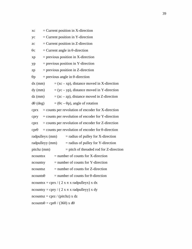
Formulation of position, rotation and direction of Gantry Mechanism
The server receives the distances and angle values from the webpage when the user
clicks “MOVE” button. The Visual Basic program on the server calculates the number
of counts, and determines the direction of motion. The number of counts and the
direction are sent to the PIC-microcontroller.
39
xc = Current position in X-direction
yc = Current position in Y-direction
zc = Current position in Z-direction
θc = Current angle in θ-direction
xp = previous position in X-direction
yp = previous position in Y-direction
zp = previous position in Z-direction
θp = previous angle in θ-direction
dx (mm) = (xc – xp), distance moved in X-direction
dy (mm) = (yc – yp), distance moved in Y-direction
dz (mm) = (zc – zp), distance moved in Z-direction
dθ (deg) = (θc – θp), angle of rotation
cprx = counts per revolution of encoder for X-direction
cpry = counts per revolution of encoder for Y-direction
cprz = counts per revolution of encoder for Z-direction
cprθ = counts per revolution of encoder for θ-direction
radpulleyx (mm) = radius of pulley for X-direction
radpulleyy (mm) = radius of pulley for Y-direction
pitchz (mm) = pitch of threaded rod for Z-direction
ncountsx = number of counts for X-direction
ncountsy = number of counts for Y-direction
ncountsz = number of counts for Z-direction
ncountsθ = number of counts for θ-direction
ncountsx = cprx / ( 2 x π x radpulleyx) x dx
ncountsy = cpry / ( 2 x π x radpulleyy) x dy
ncountsz = cprz / (pitchz) x dz
ncountsθ = cprθ / (360) x dθ

40
Vibration control of Gantry Mechanism
Many applications of control design require precise positioning of an object and fast
point to point movement. Reduction in time of movement requires reduction of inertia,
which results low frequency dynamics [15]. Precise placement requires that the
vibration of the object should be zero or close to zero. Feedback controllers are designed
to minimize the error between the reference command and the output. Input shaping of
the reference command is another technique of reducing the unbalanced vibrations.
Formulation of input shaping for vibration control
The residual vibration is reduced by generating a command profile. The command
profile cancels the vibration induced by the first part by the later part of the command.
The input command is convolved by a sequence of impulses. The resulting command is
used to drive the system.
A linear vibratory system of any order can be represented as a set of cascaded
second order system. The transfer function of a typical second order system is given by 2
2
( )( ) 2
n
n n
Y sR s s s
ω2ζω ω
=+ +
----------------------------------- (4.1)
where, Y(s) = output signal;
R(s) = reference signal;
ωn = natural frequency of the vibrating system;
ζ = damping ratio.
The impulse response of a second order system is given by the following
equation:
( )
2
( ) sin( ( ))1( ) 1
n it tnd i
Ay t e w tt
σω tω
ζ− −=
−− ----------------------------------- (4.2)
where , A = amplitude of impulse;
ti = initial time;
σ = ζ ωn ; ----------------------------------- (4.3)
21d nω ω ζ= − damped frequency. ----------------------------------- (4.4)
41
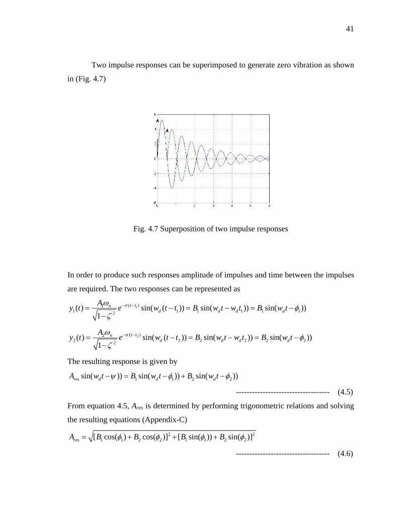
Two impulse responses can be superimposed to generate zero vibration as shown
in (Fig. 4.7)
Fig. 4.7 Superposition of two impulse responses
In order to produce such responses amplitude of impulses and time between the impulses
are required. The two responses can be represented as
1( )11 1 1 12( ) sin( ( )) sin( )) sin(
1t tn
d d dAy t e w t t B w t w t B w tσ
1 1))dω φζ
− −= − = − = −−
2( )22 2 2 22( ) sin( ( )) sin( )) sin( ))
1t tn
d d dAy t e w t t B w t w t B w tσ
2 2dω φζ
− −= − = − = −−
The resulting response is given by
1 1 2sin( )) sin( )) sin( ))res d d dA w t B w t B w t 2ψ φ φ− = − + −
----------------------------------- (4.5)
From equation 4.5, Ares is determined by performing trigonometric relations and solving
the resulting equations (Appendix-C)
2 21 1 2 2 1 1 2 2[ cos( ) cos( )] [ sin( )) sin( )]resA B B B Bφ φ φ= + + + φ
----------------------------------- (4.6)
42
The amplitude of the resultant response Ares is zero if both the terms in the square root
are zero.
1 1 2 2cos( ) cos( ) 0B Bφ φ+ =
1 1 2 2sin( )) sin( ) 0B Bφ φ+ =
1 1 2 2cos( ) cos( ) 0d dB t B tω ω+ =
1 21 1 2 22
[ cos( ) cos( )] 01
t ttnd de A e w t A e w tσ σσω
ζ− + =
−
1 21 1 2 22
[ sin( ) sin( )] 01
t ttnd de A e w t A e w tσ σσω
ζ− + =
−
Considering initial time (t1) to be zero of first response
t1 = 0 2
2 21 cos( )tdA e w tσ+ = 0 ----------------------------------- (4.7)
22 2sin( ) 0t
dA e w tσ = ----------------------------------- (4.8)
The second equation implies that 2dw t nπ= ----------------------------------- (4.9)
2 21d n
n ntw wπ π
ζ= =
−
For n=1,
2 21d n
tw wπ π
ζ= =
−, and t1 =0 ----------------------------------- (4.10)
The amplitude constraint to obtain a normalized solution requires that the sum of
amplitudes is one [15].
1 2 1A A+ = --------------------------------- (4.11)
The solution of equations 4.7, 4.9 and 4.11 give A1 and A2. 2
21 1
t
t
eAe
σ
σ=+
--------------------------------- (4.12)
221
1 tAeσ=
+ --------------------------------- (4.13)
43
A step input is convolved with the impulse amplitudes (equations 4.12 and 4.13) at time
interval given by equation 4.10.
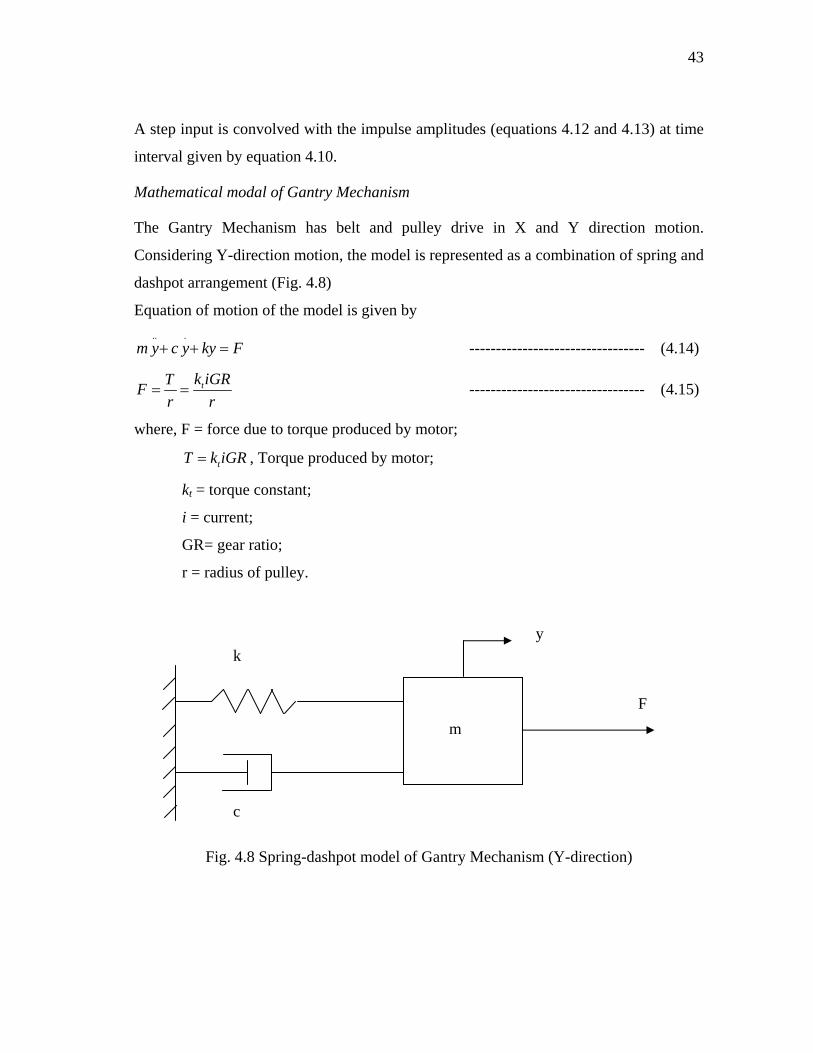
Mathematical modal of Gantry Mechanism
The Gantry Mechanism has belt and pulley drive in X and Y direction motion.
Considering Y-direction motion, the model is represented as a combination of spring and
dashpot arrangement (Fig. 4.8)
Equation of motion of the model is given by .. .
m y c y ky F+ + = --------------------------------- (4.14)
tk iGRTFr r
= = --------------------------------- (4.15)
where, F = force due to torque produced by motor;
, Torque produced by motor; tT k iGR=
kt = torque constant;
i = current;
GR= gear ratio;
r = radius of pulley.
m
y k
F
c
Fig. 4.8 Spring-dashpot model of Gantry Mechanism (Y-direction)
44
.. .
tk GRm y c y ky ir
+ + = --------------------------------- (4.16)
Laplace transform of equation 4.16, with zero initial conditions, is given by
2
( )( ) ( )
tk GRY sI s r ms cs k
=+ +
--------------------------------- (4.17)
Comparing equation 4.17 with equation 4.1, the response is given as
( )2 2
( ) sin( ( ))1( ) 1
n it tnd i
n
y t A e w tt
σω tωω ζ
− −=−
− --------------------------------- (4.18)
where, tik GRA A
r= ;
nkm
ω = ;
2
ckm
ζ = .
45
CHAPTER V
EVALUATION OF RESULTS
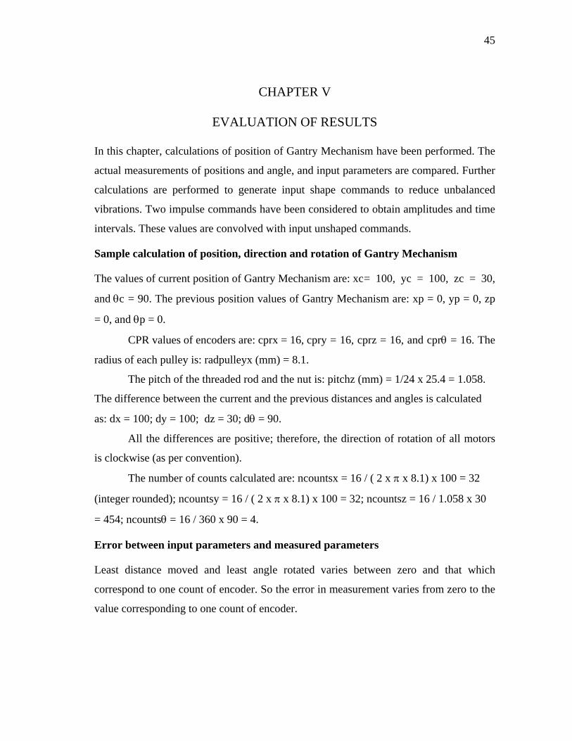
In this chapter, calculations of position of Gantry Mechanism have been performed. The
actual measurements of positions and angle, and input parameters are compared. Further
calculations are performed to generate input shape commands to reduce unbalanced
vibrations. Two impulse commands have been considered to obtain amplitudes and time
intervals. These values are convolved with input unshaped commands.
Sample calculation of position, direction and rotation of Gantry Mechanism
The values of current position of Gantry Mechanism are: xc = 100, yc = 100, zc = 30,
and θc = 90. The previous position values of Gantry Mechanism are: xp = 0, yp = 0, zp
= 0, and θp = 0.
CPR values of encoders are: cprx = 16, cpry = 16, cprz = 16, and cprθ = 16. The
radius of each pulley is: radpulleyx (mm) = 8.1.
The pitch of the threaded rod and the nut is: pitchz (mm) = 1/24 x 25.4 = 1.058.
The difference between the current and the previous distances and angles is calculated
as: dx = 100; dy = 100; dz = 30; dθ = 90.
All the differences are positive; therefore, the direction of rotation of all motors
is clockwise (as per convention).
The number of counts calculated are: ncountsx = 16 / ( 2 x π x 8.1) x 100 = 32
(integer rounded); ncountsy = 16 / ( 2 x π x 8.1) x 100 = 32; ncountsz = 16 / 1.058 x 30
= 454; ncountsθ = 16 / 360 x 90 = 4.
Error between input parameters and measured parameters
Least distance moved and least angle rotated varies between zero and that which
correspond to one count of encoder. So the error in measurement varies from zero to the
value corresponding to one count of encoder.
46
Least distance moved in X-direction, dxl, is ( 2 x π x radpulleyx) / cprx, in Y-
direction, dyl, is ( 2 x π x radpulleyy) / cpry, in Z-direction is (pitchz) / cprz, and in θ-
direction, dθl, is (360) / cprθ.
Hence, the values calculated are: dxl = ( 2 x π x 8.1) / 16= 3.2 mm, dyl = ( 2 x π
x 8.1) / 16 = 3.2 mm, dzl = 1.058 / 16 = 0.07 mm, and dθl = 360 / 16 = 22.5 degree.
Table 5.1 shows the ranges of errors. Table 5.2 shows the input data, the output
measured values, and the difference between the input and output parameters.
Table 5.1 Expected error between input and measured parameter
Expected Error in
X-direction (mm)
Y-direction
(mm)
Z-direction
(mm)
θ-direction
(degree)
0 to 3.2 0 to 3.2 0 to 0.07 0 to 22.5

47
Table 5.2 Comparison of input and measured distances and angles
S.
No.
Input parameter
(distance in mm
and angle in deg.)
Measured parameter
(distance in mm and
angle in deg.)
Difference between
Measured and Input
parameter
X Y Z θ X Y Z θ ΔX ΔY ΔZ Δθ
1 20 20 10 45 20 20 10 43 0 0 0 -2
2 40 40 20 90 41 44 20 105 1 4 0 15
3 60 60 30 135 60 59 29 135 0 -1 -1 0
4 80 80 40 180 80 83 39 200 0 3 -1 20
5 100 100 50 225 101 105 50 225 1 2 0 0
6 150 150 60 270 153 148 59 290 3 -2 -1 20
7 200 200 315 201 205 335 1 5 20
8 250 250 360 248 248 380 -2 -2 20
9 300 297 -3
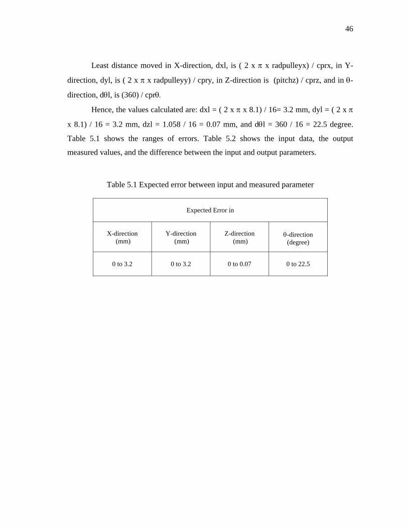
The error in input distance in X direction varies from -3mm to 3mm (Fig. 5.1).
The negative value is due to the system dynamics. The elasticity of belt and friction due
to wheels and the railing are the causes of this difference. As the distance of travel
increases, the system becomes more and more accelerated, so the fluctuation in error
also increases.
48
Graph between Input distance and *Error for X-direction
-4
-3
-2
-1
0
1
2
3
4
20 40 60 80 100 150 200 250 300
Input distance (mm)
*Erro
r (m
m)
*Error-X
*Error: It is the difference between the input distance and the measured distance.
Fig. 5.1 Input distance vs error (X-direction)
In case of Y-direction motion the error varies between -2 mm and 5mm, which
can again be accounted for the same reason as for X-direction motion (Fig. 5.2). The
fluctuation in error also increases with the distance traveled. However, since the inertia
reduces, so the fluctuation is not as high as in the case of X-direction motion.
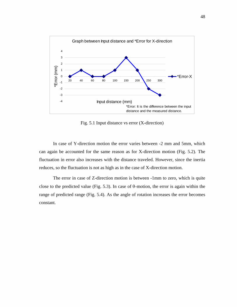
The error in case of Z-direction motion is between -1mm to zero, which is quite
close to the predicted value (Fig. 5.3). In case of θ-motion, the error is again within the
range of predicted range (Fig. 5.4). As the angle of rotation increases the error becomes
constant.

49
Graph between Input distance and *Error for Y-direction
-3
-2
-1
0
1
2
3
4
5
6
20 40 60 80 100 150 200 250
Input distance (mm)
*Erro
r (m
m)
*Error-Y
*Error: It is the difference between the input distance and the measured distance.
Fig. 5.2 Input distance vs error (Y-direction)
Graph between Input distance and *Error for Z-direction
-1.2
-1
-0.8
-0.6
-0.4
-0.2
010 20 30 40 50 60
Input distance (mm)
*Erro
r (m
m)
*Error-Z
*Error: It is the difference between the input distance and the measured distance.
Fig. 5.3 Input distance vs error (Z-direction)
50
Graph between Input distance and *Error for θ-direction
-5
0
5
10
15
20
25
45 90 135 180 225 270 315 360
Input angle (degree)
*Erro
r (de
gree
)
Error-theta
*Error: It is the difference between the input distance and the measured distance.
Fig. 5.4 Input angle vs error (θ-direction)
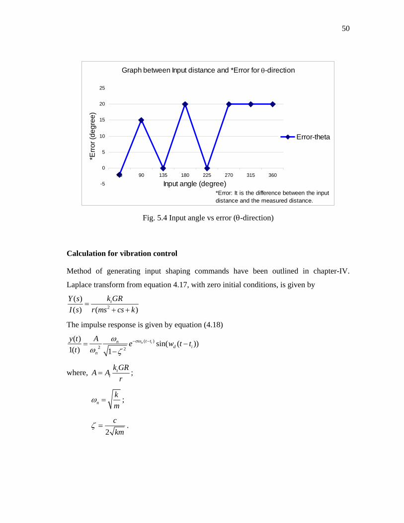
Calculation for vibration control
Method of generating input shaping commands have been outlined in chapter-IV.
Laplace transform from equation 4.17, with zero initial conditions, is given by
2
( )( ) ( )
tk GRY sI s r ms cs k
=+ +
The impulse response is given by equation (4.18)
( )2 2
( ) sin( ( ))1( ) 1
n it tnd i
n
y t A e w tt
σω tωω ζ
− −= −−
where, tik GRA A
r= ;
nkm
ω = ;
2
ckm
ζ = .
51
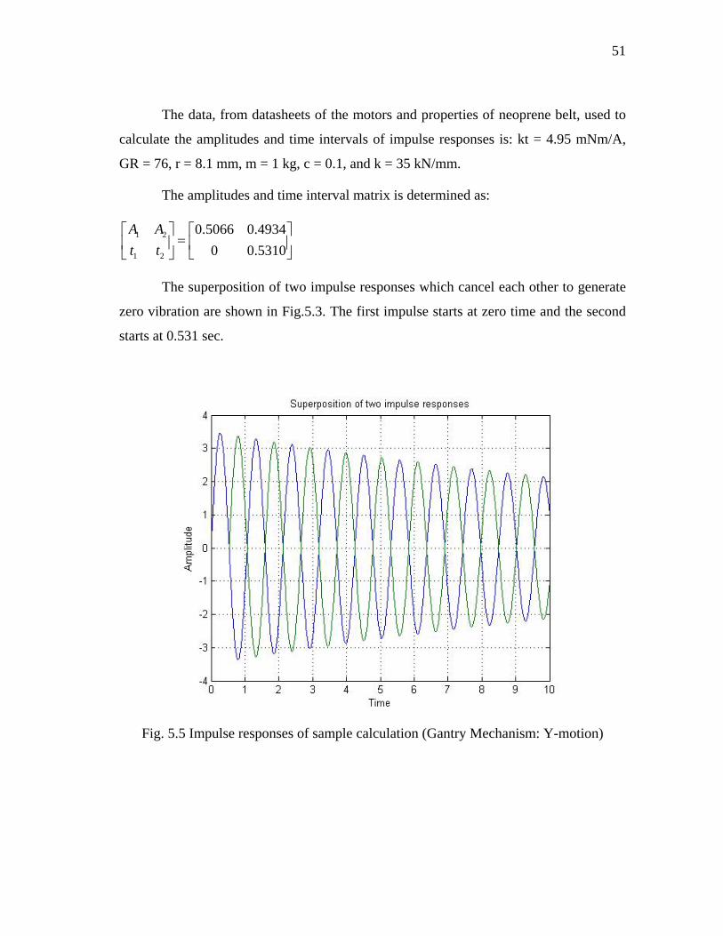
The data, from datasheets of the motors and properties of neoprene belt, used to
calculate the amplitudes and time intervals of impulse responses is: kt = 4.95 mNm/A,
GR = 76, r = 8.1 mm, m = 1 kg, c = 0.1, and k = 35 kN/mm.
The amplitudes and time interval matrix is determined as:
1 2
1 2
0.5066 0.49340 0.5310
A At t
⎡ ⎤ ⎡ ⎤=⎢ ⎥ ⎢ ⎥
⎣ ⎦⎣ ⎦
The superposition of two impulse responses which cancel each other to generate
zero vibration are shown in Fig.5.3. The first impulse starts at zero time and the second
starts at 0.531 sec.
Fig. 5.5 Impulse responses of sample calculation (Gantry Mechanism: Y-motion)
52
CHAPTER VI
SUMMARY AND CONCLUSIONS
Summary
The research objective is to build a Gantry Mechanism and control it over the Internet.
The mechanism will be used to view the working of a SCARA robot. A model of the
Gantry Mechanism is designed, built and controlled over the Internet. The Gantry
Mechanism maneuvers the camera in the working envelope. The camera captures the
images and transmits them over the Internet. In this way, the user virtually sees the
working space from different positions.
The Gantry Mechanism has four degrees of freedom along X, Y, Z and θ-
direction in the X-Y plane. The X and Y motion has belt-pulley transmission. The Z-
direction motion consists of threaded rod and nut arrangement. Finally, in the θ-motion,
the motor is directly coupled with the shaft carrying the camera.
The control of the Gantry Mechanism is implemented in two parts. The feedback
control loop is built using motors, H-bridge, logic gates, encoders and PIC-
microcontroller. The reference input is obtained from the user, who uses a Graphical
User Interface in the web-browser on the client side. The reference command is
processed on the server to generate input commands for the feedback loop.
Further to reduce the unbalanced vibrations of the Gantry Mechanism, an
algorithm of input command shaping has been developed. The algorithm involves
calculation of impulse amplitudes and their time-intervals of application. These impulse
commands are convolved with actual step command to generate inputs to the motors.
Future work
Improvement in the design of feedback control loop along with input shaping will,
further, reduce the error in input parameters and measured parameters. The setup
designed is cost-effective. Motor controllers with position feedback can be used with
53
MATLAB to make more robust system. However, one has to learn how to write
programs and make interfaces which would bridge between client, MATLAB programs
and PIC-microcontroller. Finally, the Graphical User Interface can be improved by
shifting from HTML and Javascript programming to Java3D.
Conclusions
In this research the objective of designing a Gantry Mechanism and its control through
the Internet has been achieved. A model of the Gantry Mechanism was built and also
developed its control through the Internet. The experimental results were evaluated by
comparing the predicted errors and actual errors. Suggestions for the system
improvement and error reduction were outlined. The design can be scaled up to develop
an actual Gantry Mechanism for the experimentation of the SCARA Robot. Finally, the
unbalanced vibrations can be reduced by implementing the input shaping algorithm and
improvement in feedback control loop.
The applications of the Gantry Mechanism, which maneuvers the camera and is
controlled over the Internet, include industry, viewing inaccessible places like nuclear
plants, shop floors, hospitals, underwater, space and home security systems.
54
REFERENCES
[1] H. Yang, R. Eagleson, “Design and implementation of an internet-based embedded
control system”, in IEEE Conference on Control Applications - Proceedings, vol 2,
2003, pp 1181-1185.
[2] W.J. Kim, K. Ji, Kun, A. Ambike, “Real time operating environment for networked
control systems”, IEEE Transactions on Control Systems Technology, submitted for
publication.
[3] P.X. Liu, , M. Meng, Q. H. Max, J. Gu, S.X. Yang, C. Hu, “Control and data
transmission for internet robots”, in Proc. - IEEE International Conference on
Robotics and Automation, vol 2, 2003, pp 1659-1664.
[4] S.K. Ong, W.W. Sun, “Application of mobile agents in a web-based real-time
monitoring system” International Journal of Advanced Manufacturing Technology,
vol 22, no. 1-2, 2003, pp 33-40.
[5] R. B. Sepe Jr., N. Short, M. Chamberland, “Web-based Virtual Engineering
Laboratory (VE-LAB) for a hybrid electric vehicle starter/alternator”, in Conf. Rec.
IAS Annual Meeting (IEEE Industry Applications Society), vol 4, 1999, pp 2642-
2648.
[6] L. Wang, W. Shen, S. Lang, “Wise-ShopFloor: A Web-Based and Sensor-Driven
Shop Floor Environment” in Proc. of the International Conference on Computer
Supported Cooperative Work in Design, Proceedings of the Seventh International
Conference on CSCW in Design, vol 7, pp 413-418, 2002.
[7] L. Wang, R. Sams, M. Verner, F. Xi, “Integrating Java 3D model and sensor data
for remote monitoring and control”, Robotics and Computer-Integrated
Manufacturing, vol 19, no. 1-2, pp 13-19, 2003.
[8] L. Wang, P. Orban, A. Cunningham, S. Lang, “Remote real-time CNC machining
for web-based manufacturing”, Robotics and Computer-Integrated Manufacturing,
vol 20, no. 6, pp 563-571, 2004.
55
[9] M. Wang, J. N. K. Liu, “Interactive control for Internet-based mobile robot
teleoperation”, Robotics and Autonomous Systems, vol 52, no. 2-3, pp 160-179,
2005.
[10] R.C. Luo, M. C. Tse, C. C. Yih, “Intelligent autonomous mobile robot control
through the internet”, IEEE International Symposium on Industrial Electronics, vol
1, pp PL6-PL11, 2000.
[11] A. Malinowski, T. Konetski, B. Davis, D. Schertz, “Web-controlled robotic
manipulator using Java and client-server architecture”, in Proc. IECON (Industrial
Electronics Conference), vol 2, pp 827-830, 1999.
[12] T. M. Sobh, R. Sanyai, B. Wang, “Remote surveillance via wireless-controlled
mobile robots”, in Proc. Sixth Biannual World Automation Congress, WAC,
Robotics: Trends, Principles, and Application.. pp 541-546, 2004.
[13] L. Chen, Y. Wang, “Design and implementation of a web-based distributed control
system (WDCS)”, in Canadian Conference on Electrical and Computer
Engineering, vol 2, 2002, pp 681-686.
[14] H. Wu, J. Ming, Y. Yang, S. Zhu, “Integrating embedded-web technology and real-
time Ethernet for modern distributed control” in Proc. World Congress on
Intelligent Control and Automation (WCICA), WCICA 2004 - Fifth World Congress
on Intelligent Control and Automation, Conference Proceedings, vol 2, 2004, pp
1323-1325.
[15] T. Singh, W. Singhose, “Tutorial on Input Shaping/Time Delay Control of
Maneuvering Flexible Structues” )”, in Proceedings of the American Control
Conference Anchorage, AK, pp 1717-1731, 2002.
[16] R. Beardmore, “Mechanical Engineering Design and Engineering Materials”, last
updated 06-06-2007, [online] Available: www.roymech.co.uk/index3.htm.
56
APPENDIX
Appendix A
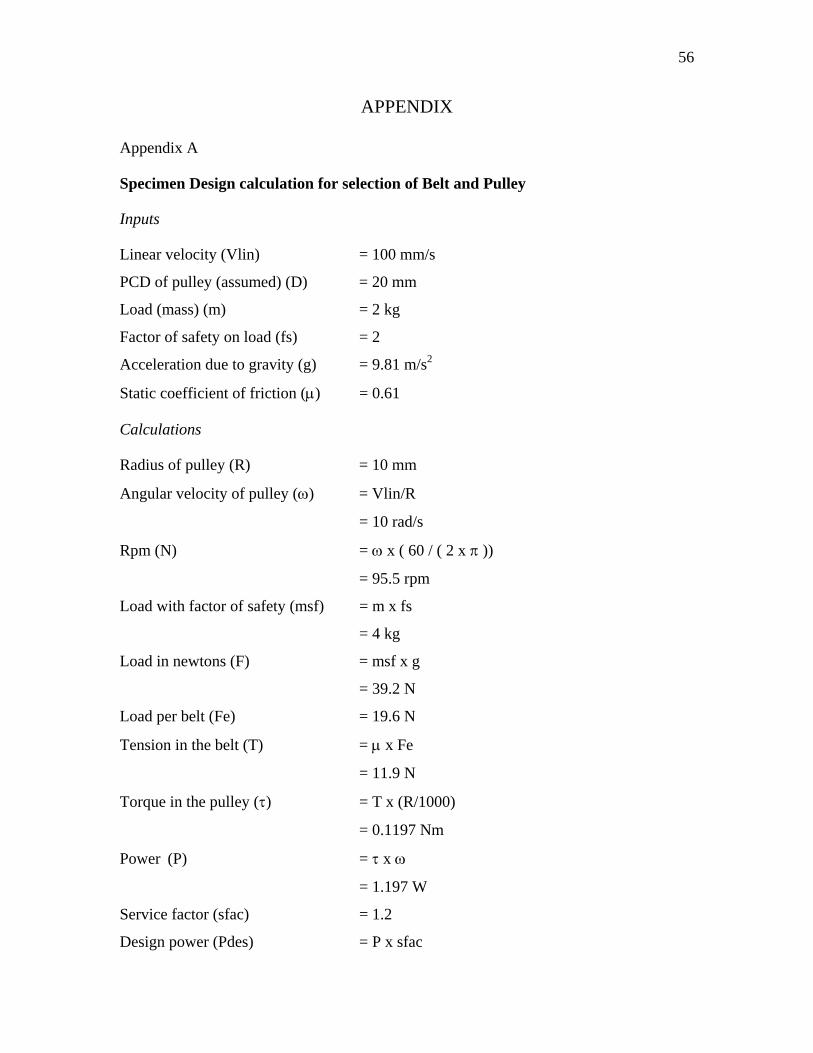
Specimen Design calculation for selection of Belt and Pulley
Inputs
Linear velocity (Vlin) = 100 mm/s
PCD of pulley (assumed) (D) = 20 mm
Load (mass) (m) = 2 kg
Factor of safety on load (fs) = 2
Acceleration due to gravity (g) = 9.81 m/s2
Static coefficient of friction (μ) = 0.61
Calculations
Radius of pulley (R) = 10 mm
Angular velocity of pulley (ω) = Vlin/R
= 10 rad/s
Rpm (N) = ω x ( 60 / ( 2 x π ))
= 95.5 rpm
Load with factor of safety (msf) = m x fs
= 4 kg
Load in newtons (F) = msf x g
= 39.2 N
Load per belt (Fe) = 19.6 N
Tension in the belt (T) = μ x Fe
= 11.9 N
Torque in the pulley (τ) = T x (R/1000)
= 0.1197 Nm
Power (P) = τ x ω
= 1.197 W
Service factor (sfac) = 1.2
Design power (Pdes) = P x sfac
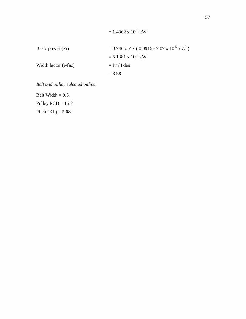
57
= 1.4362 x 10⁻³ kW
Basic power (Pr) = 0.746 x Z x ( 0.0916 - 7.07 x 10⁻⁵ x Z2 )
= 5.1381 x 10⁻³ kW
Width factor (wfac) = Pr / Pdes
= 3.58
Belt and pulley selected online
Belt Width = 9.5
Pulley PCD = 16.2
Pitch (XL) = 5.08
58
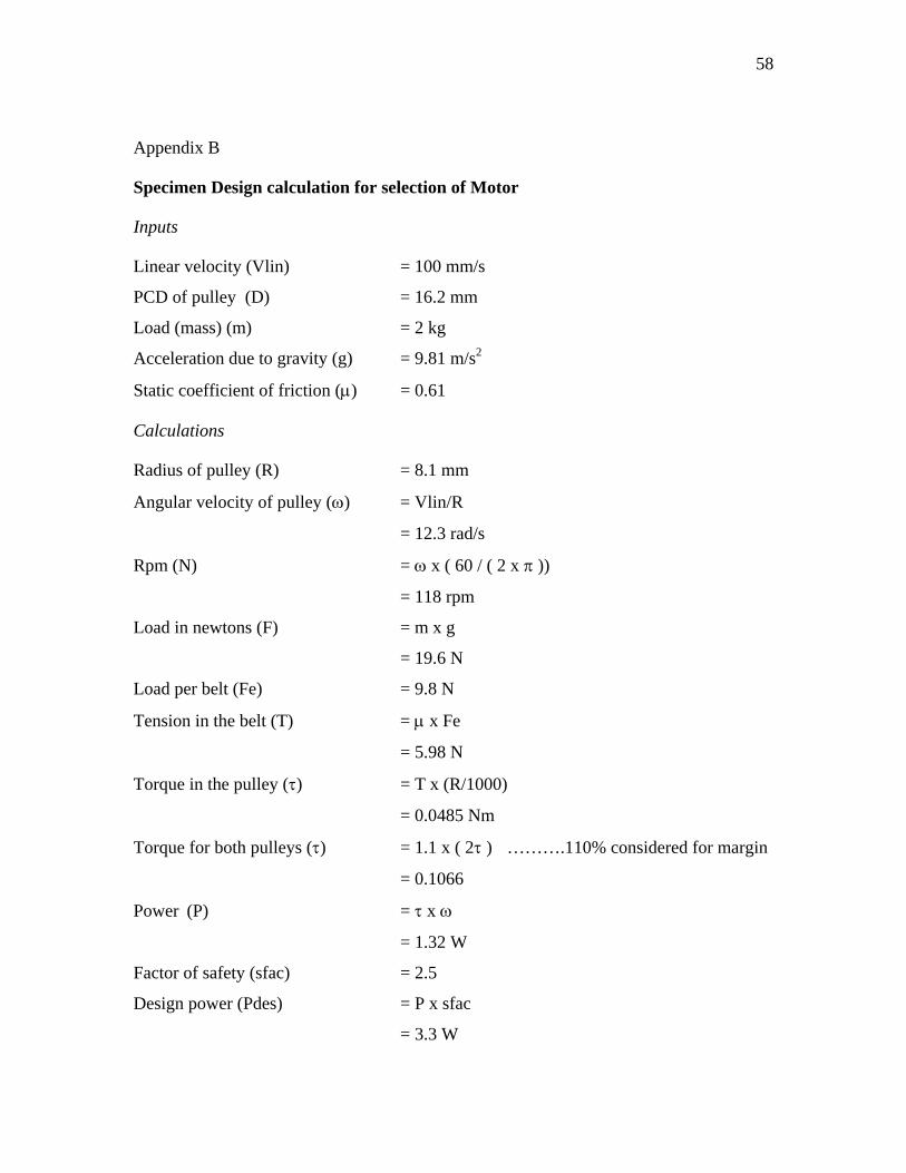
Appendix B
Specimen Design calculation for selection of Motor
Inputs
Linear velocity (Vlin) = 100 mm/s
PCD of pulley (D) = 16.2 mm
Load (mass) (m) = 2 kg
Acceleration due to gravity (g) = 9.81 m/s2
Static coefficient of friction (μ) = 0.61
Calculations
Radius of pulley (R) = 8.1 mm
Angular velocity of pulley (ω) = Vlin/R
= 12.3 rad/s
Rpm (N) = ω x ( 60 / ( 2 x π ))
= 118 rpm
Load in newtons (F) = m x g
= 19.6 N
Load per belt (Fe) = 9.8 N
Tension in the belt (T) = μ x Fe
= 5.98 N
Torque in the pulley (τ) = T x (R/1000)
= 0.0485 Nm
Torque for both pulleys (τ) = 1.1 x ( 2τ ) ……….110% considered for margin
= 0.1066
Power (P) = τ x ω
= 1.32 W
Factor of safety (sfac) = 2.5
Design power (Pdes) = P x sfac
= 3.3 W
59
Motor selected
Power (P) = 4.0 W
Operating voltage (V) = 12 V
No-load speed (ωn) = 11500 rpm
Stall Torque (τs) = 14.4 mNm
Gearhead reduction ratio = 104:1
Maximum power output (Pmax) = τs /2 x ωn /2
at τs /2 and ωn /2 = 4.34 W
Speed at maximum power (ωmax) = 11500 / 2
= 5750
Torque at maximum power (τmax) = 14.4 / 2
= 7.2 mNm
Operating voltage range = 5V to 12 V
Operating speed range = 11500 x (5/12 to 12/12)
= 4792 to 11500
Torque at constant speed (τ ) = τs – (τs / ωn) ω
Operating torque range = 8.4 to 0 mNm
Operating torque range at Gearhead = 0 to 873.6 mNm = 0 to 0.8736 Nm
Torque required = 0.1066 Nm
% margin over torque = 75
60
Appendix-C
1 1 2sin( )) sin( )) sin( ))res d d dA w t B w t B w t 2ψ φ φ− = − + −
Expanding the trigonometric expressions on both sides
1 1 1 2 2
(sin( ) cos( ) cos( )sin( ))(sin( ) cos( ) cos( )sin( )) (sin( ) cos( ) cos( )sin( )
res d d
d d d d
A w t w tB w t w t B w t w t 2 )
ψ ψφ φ φ
−= − + − φ
This can be written as
1 1 2 2 1 1 2 2
sin( )[ cos( )] cos( )[ sin( )]sin( )[ cos( ) cos( )] cos( )[ sin( )) sin( )]
d res d res
d d
w t A w t Aw t B B w t B B
ψ ψφ φ φ
−= + − + φ
2
Equating the coefficients of sine and cosine terms on both sides
1 1 2cos( ) cos( ) cos( )resA B Bψ φ φ= +
1 1 2sin( ) sin( )) sin(resA B B 2 )ψ φ φ= +
Squaring and adding both sides 2 2
1 1 2 2 1 1 2 2[ cos( ) cos( )] [ sin( )) sin( )]resA B B B Bφ φ φ= + + + 2φ
2 21 1 2 2 1 1 2 2[ cos( ) cos( )] [ sin( )) sin( )]resA B B B Bφ φ φ= + + + φ
61
VITA
Name: Surinder Pal
Address: Texas A&M University
Department of Mechanical Engineering
3123 TAMU
College Station, TX 77843-3123
Email Address: [email protected]
Education: B. Tech., Mechanical Engineering, Indian Institute of
Technology, Bombay, 1997
M.S., Mechanical Engineering, Texas A & M University,
2007