Embed Size (px)
Citation preview
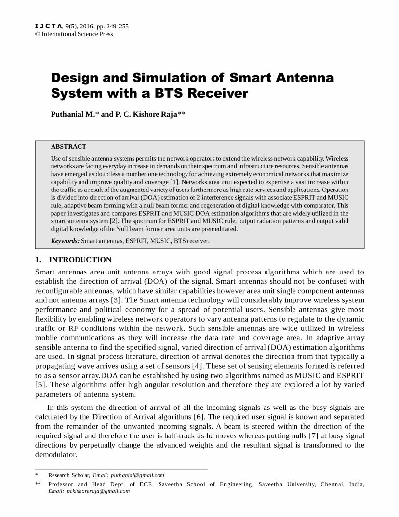
I J C T A, 9(5), 2016, pp. 249-255© International Science Press
Design and Simulation of Smart AntennaSystem with a BTS ReceiverPuthanial M.* and P. C. Kishore Raja**
ABSTRACT
Use of sensible antenna systems permits the network operators to extend the wireless network capability. Wirelessnetworks are facing everyday increase in demands on their spectrum and infrastructure resources. Sensible antennashave emerged as doubtless a number one technology for achieving extremely economical networks that maximizecapability and improve quality and coverage [1]. Networks area unit expected to expertise a vast increase withinthe traffic as a result of the augmented variety of users furthermore as high rate services and applications. Operationis divided into direction of arrival (DOA) estimation of 2 interference signals with associate ESPRIT and MUSICrule, adaptive beam forming with a null beam former and regeneration of digital knowledge with comparator. Thispaper investigates and compares ESPRIT and MUSIC DOA estimation algorithms that are widely utilized in thesmart antenna system [2]. The spectrum for ESPRIT and MUSIC rule, output radiation patterns and output validdigital knowledge of the Null beam former area units are premeditated.
Keywords: Smart antennas, ESPRIT, MUSIC, BTS receiver.
1. INTRODUCTION
Smart antennas area unit antenna arrays with good signal process algorithms which are used toestablish the direction of arrival (DOA) of the signal. Smart antennas should not be confused withreconfigurable antennas, which have similar capabilities however area unit single component antennasand not antenna arrays [3]. The Smart antenna technology will considerably improve wireless systemperformance and political economy for a spread of potential users. Sensible antennas give mostflexibility by enabling wireless network operators to vary antenna patterns to regulate to the dynamictraffic or RF conditions within the network. Such sensible antennas are wide utilized in wirelessmobile communications as they will increase the data rate and coverage area. In adaptive arraysensible antenna to find the specified signal, varied direction of arrival (DOA) estimation algorithmsare used. In signal process literature, direction of arrival denotes the direction from that typically apropagating wave arrives using a set of sensors [4]. These set of sensing elements formed is referredto as a sensor array.DOA can be established by using two algorithms named as MUSIC and ESPRIT[5]. These algorithms offer high angular resolution and therefore they are explored a lot by variedparameters of antenna system.
In this system the direction of arrival of all the incoming signals as well as the busy signals arecalculated by the Direction of Arrival algorithms [6]. The required user signal is known and separatedfrom the remainder of the unwanted incoming signals. A beam is steered within the direction of therequired signal and therefore the user is half-track as he moves whereas putting nulls [7] at busy signaldirections by perpetually change the advanced weights and the resultant signal is transformed to thedemodulator.
* Research Scholar, Email: [email protected]
** Professor and Head Dept. of ECE, Saveetha School of Engineering, Saveetha University, Chennai, India,Email: [email protected]
250 Puthanial M. and P. C. Kishore Raja
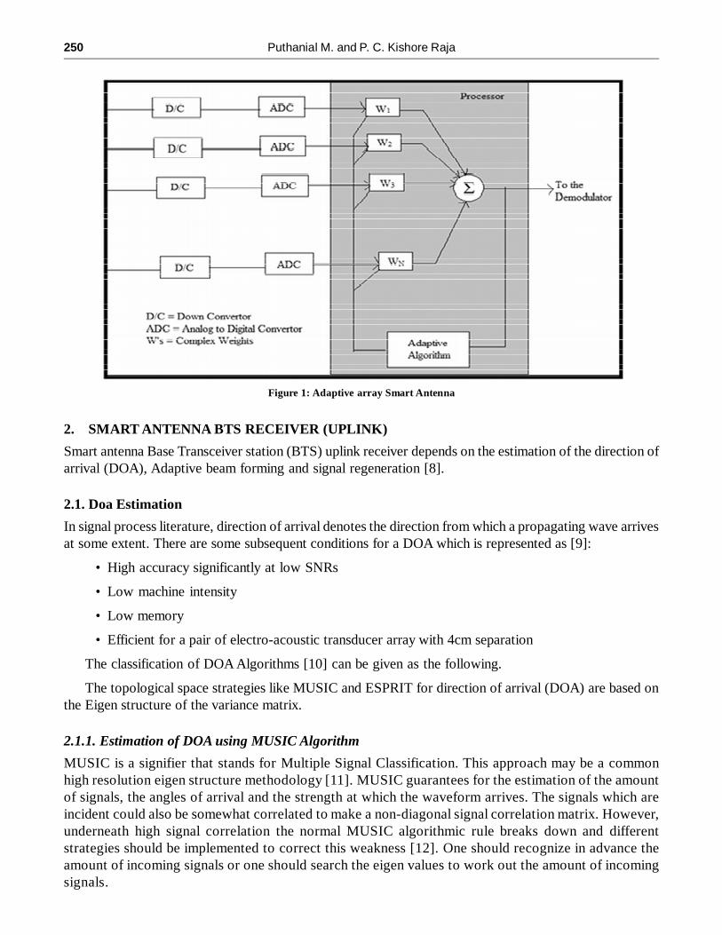
2. SMART ANTENNA BTS RECEIVER (UPLINK)
Smart antenna Base Transceiver station (BTS) uplink receiver depends on the estimation of the direction ofarrival (DOA), Adaptive beam forming and signal regeneration [8].
2.1. Doa Estimation
In signal process literature, direction of arrival denotes the direction from which a propagating wave arrivesat some extent. There are some subsequent conditions for a DOA which is represented as [9]:
• High accuracy significantly at low SNRs
• Low machine intensity
• Low memory
• Efficient for a pair of electro-acoustic transducer array with 4cm separation
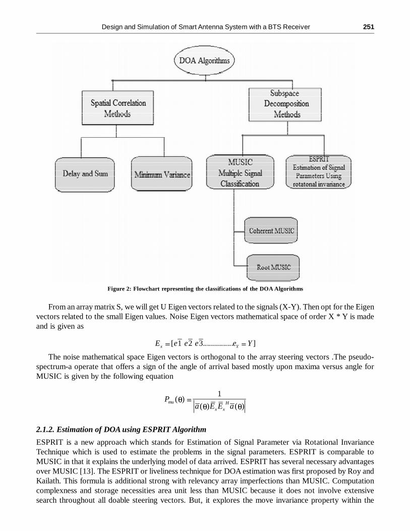
The classification of DOA Algorithms [10] can be given as the following.
The topological space strategies like MUSIC and ESPRIT for direction of arrival (DOA) are based onthe Eigen structure of the variance matrix.
2.1.1. Estimation of DOA using MUSIC Algorithm
MUSIC is a signifier that stands for Multiple Signal Classification. This approach may be a commonhigh resolution eigen structure methodology [11]. MUSIC guarantees for the estimation of the amountof signals, the angles of arrival and the strength at which the waveform arrives. The signals which areincident could also be somewhat correlated to make a non-diagonal signal correlation matrix. However,underneath high signal correlation the normal MUSIC algorithmic rule breaks down and differentstrategies should be implemented to correct this weakness [12]. One should recognize in advance theamount of incoming signals or one should search the eigen values to work out the amount of incomingsignals.
Figure 1: Adaptive array Smart Antenna
Design and Simulation of Smart Antenna System with a BTS Receiver 251
From an array matrix S, we will get U Eigen vectors related to the signals (X-Y). Then opt for the Eigenvectors related to the small Eigen values. Noise Eigen vectors mathematical space of order X * Y is madeand is given as
[ 1 2 3............... ]x xE e e e e Y
The noise mathematical space Eigen vectors is orthogonal to the array steering vectors .The pseudo-spectrum-a operate that offers a sign of the angle of arrival based mostly upon maxima versus angle forMUSIC is given by the following equation
1( )
( ) ( )mu H
x x
Pa E E a
2.1.2. Estimation of DOA using ESPRIT Algorithm
ESPRIT is a new approach which stands for Estimation of Signal Parameter via Rotational InvarianceTechnique which is used to estimate the problems in the signal parameters. ESPRIT is comparable toMUSIC in that it explains the underlying model of data arrived. ESPRIT has several necessary advantagesover MUSIC [13]. The ESPRIT or liveliness technique for DOA estimation was first proposed by Roy andKailath. This formula is additional strong with relevancy array imperfections than MUSIC. Computationcomplexness and storage necessities area unit less than MUSIC because it does not involve extensivesearch throughout all doable steering vectors. But, it explores the move invariance property within the
Figure 2: Flowchart representing the classifications of the DOA Algorithms

252 Puthanial M. and P. C. Kishore Raja
signal mathematical space created by 2 sub arrays derived from original array with a translation invariablenessstructure not like MUSIC.
The Angle-of-Arrival of the ESPRIT algorithm can be established as [13]
1cos [ (arg( )) / ]k kc X
Where as �k represents the value of the Eigen vectors
From the above discussion it can be stated as the ESPRIT eliminates the search procedure inherentin most DOA estimation strategies. ESPRIT produces the DOA estimation directly in terms of theEigenvalues [14].
2.2. Adaptive Beamforming
Beam forming may be a signal process technique accustomed management the radial asymmetry of thetransmission and reception of radio signals [15]. Adaptive beam forming may be an ordinarily utilizedtechnique that enables system operation in associate degree interference environment by adaptively modifyingthe systems antenna pattern thus that nulls square measure generated within the angular locations of theinterference sources. This approach is applicable to scenarios wherever multiple antenna components squaremeasure individually weighted to supply a desired radial asymmetry pattern. A typical methodology offorming the adaptative weights is via the MVDR algorithmic rule, which implements one linear constraintthat maintains unit gain within the bore sight direction
2.2.1. Null Beam Former
Null beam forming is a technique of spatial signal process by which the multiple antenna transmitterswill null multiuser interference signals in wireless communications [16]. Null-Steering could be atechnique of beam forming for narrowband signals generally to create higher use of the antennaarrays.
The null steering beam former adapts the antenna pattern to steer the most beam towards the requiredusers and places nulls within the direction of officious users. Specifically, null steering may be a methodologyof beam forming for narrow band signals where we would like to possess a straightforward method ofcompensating delays of receiving signals from specific supply at totally different elements of the antennaarray. To achieve this goal, we may only add the weighted version of the signals with applicable weightedvalues [17]. We have a tendency to do that in such how that the frequency domain output of this weightedtotal produces a zero result. This methodology is named as null steering.
2.3. SIGNAL GENERATION
Applied null beam former rule place a main beam into the direction of the user and broad nulls into thedirections of interfering signals [18]. For regeneration comparator is employed, which compare incomingknowledge signal with a threshold worth of 0.5 and manufacture valid digital output knowledge removingdistortions.
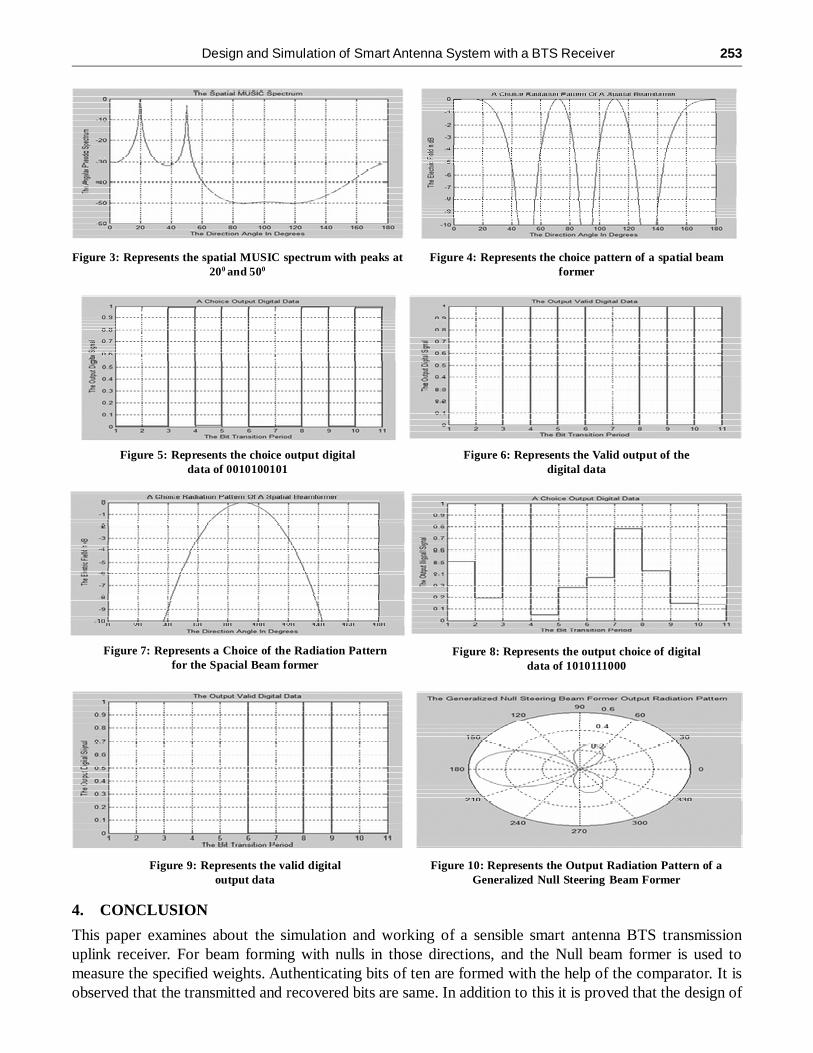
3. SIMULATION RESULTS
For the purpose of simulation assuming N = 4 and N = 8 linear array elements with a signal to noise ratioper sample 20dB are assumed. The simulation is carried using MATLAB assuming wide bands. The operationis classified into three stages which are followed as the estimation of the spacial spectrum of MUSIC andESPRIT, null beam former and finally the comparable digital outputs.
Design and Simulation of Smart Antenna System with a BTS Receiver 253
Figure 3: Represents the spatial MUSIC spectrum with peaks at200 and 500
Figure 4: Represents the choice pattern of a spatial beamformer
Figure 5: Represents the choice output digitaldata of 0010100101
Figure 6: Represents the Valid output of thedigital data
Figure 7: Represents a Choice of the Radiation Patternfor the Spacial Beam former
Figure 8: Represents the output choice of digitaldata of 1010111000
Figure 9: Represents the valid digitaloutput data
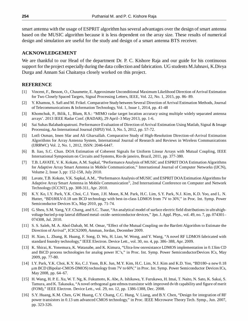
Figure 10: Represents the Output Radiation Pattern of aGeneralized Null Steering Beam Former
4. CONCLUSION
This paper examines about the simulation and working of a sensible smart antenna BTS transmissionuplink receiver. For beam forming with nulls in those directions, and the Null beam former is used tomeasure the specified weights. Authenticating bits of ten are formed with the help of the comparator. It isobserved that the transmitted and recovered bits are same. In addition to this it is proved that the design of
254 Puthanial M. and P. C. Kishore Raja
smart antenna with the usage of ESPRIT algorithm has several advantages over the design of smart antennabased on the MUSIC algorithm because it is less dependent on the array size. These results of numericaldesign and simulation are useful for the study and design of a smart antenna BTS receiver.
ACKNOWLEDGEMENT
We are thankful to our Head of the department Dr. P. C. Kishore Raja and our guide for his continuoussupport for the project especially during the data collection and fabrication. UG students M.Jahnavi, K.DivyaDurga and Annam Sai Chaitanya closely worked on this project.
REFERENCE[1] Vincent, F., Besson, O., Chaumette, E. Approximate Unconditional Maximum Likelihood Direction of Arrival Estimation
for Two Closely Spaced Targets, Signal Processing Letters, IEEE, Vol. 22, No. 1, 2015, pp. 86- 89.
[2] Y. Khamou, S. Safi and M. Frikel. Comparative Study between Several Direction of Arrival Estimation Methods, Journalof Telecommunications & Information Technology, Vol. 1, Issue 1, 2014, pp. 41-48
[3] Khomchuk, P., Bilik, I., Blum, R.S.: “MIMO radar target location accuracy using multiple widely separated antennaarrays’. 2013 IEEE Radar Conf. (RADAR), 29 April–3 May 2013, pp. 1-6.
[4] Sai Suhas Balabadrapatruni. Performance Evaluation of Direction of Arrival Estimation Using Matlab, Signal & ImageProcessing, An International Journal (SIPIJ) Vol. 3, No. 5, 2012, pp. 57-72.
[5] Lotfi Osman, Imen Sfar and Ali Gharsallah. Comparative Study of High-Resolution Direction-of-Arrival EstimationAlgorithms for Array Antenna System, International Journal of Research and Reviews in Wireless Communications(IJRRWC) Vol. 2, No. 1, 2012, ISSN: 2046-6447.
[6] B. liao, S.C. Chan. DOA Estimation of Coherent Signals for Uniform Linear Arrays with Mutual Coupling, IEEEInternational Symposium on Circuits and Systems, Rio de janeiro, Brazil, 2011, pp. 377-380.
[7] T.B. LAVATE, V. K. Kokate, A.M. Sapkal, “Performance Analysis of MUSIC and ESPRIT DOA Estimation Algorithmsfor Adaptive Array Smart Antenna in Mobile Communication,” International Journal of Computer Networks (IJCN),Volume 2, Issue 3, pp: 152-158, July 2010.
[8] Lavate, T.B. Kokate, V.K. Sapkal, A.M., “Performance Analysis of MUSIC and ESPRIT DOA Estimation Algorithms forAdaptive Array Smart Antenna in Mobile Communication”, 2nd International Conference on Computer and NetworkTechnology (ICCNT), pp. 308-311, Apr. 2010.
[9] K.Y. Ko, I.Y. Park, Y.K. Choi, C.J. Yoon, J.H. Moon, K.M. Park, H.C. Lim, S.Y. Park, N.J. Kim, K.D. Yoo, and L. N.Hutter, “BD180LV-0.18 um BCD technology with best-in-class LDMOS from 7V to 30V,” in Proc. Int. Symp. PowerSemiconductor Devices ICs, May 2010, pp. 71-74.
[10] G. Sheu, S.M. Yang, Y.F. Chang, and S.C. Tsaur, “An analytical model of surface electric field distributions in ultrahigh-voltage buried p-top lateral diffused metal–oxide–semiconductor devices,” Jpn. J. Appl. Phys., vol. 49, no. 7, pp. 074301–074308, Jul. 2010.
[11] S. S. Saleh, M. A. Abol-Dahab, M. M. Omar, “Effect of the Mutual Coupling on the Bartlett Algorithm to Estimate theDirection of Arrival”, ICICS2009, Amman, Jordan, December 2009.
[12] H. Xiao, L. Zhang, R. Huang, F. Song, D. Wu, H. Liao, W. Wong, and Y. Wang, “A novel RF LDMOS fabricated withstandard foundry technology,” IEEE Electron. Device Lett., vol. 30, no. 4, pp. 386–388, Apr. 2009.
[13] K. Shirai, K. Yonemura, K. Watanabe, and K. Kimura, “Ultra-low onresistance LDMOS implementation in 0.13ìm CDand BiCD process technologies for analog power IC’s,” in Proc. Int. Symp. Power SemiconductorDevices ICs, May2009, pp. 77-80.
[14] I.Y. Park, Y.K. Choi, K.Y. Ko, C.J. Yoon, B.K. Jun, M.Y. Kim, H.C. Lim, N.J. Kim and K.D. Yoo, “BD180–a new 0.18�m BCD (Bipolar-CMOS-DMOS) technology from 7V to 60V,” in Proc. Int. Symp. Power Semiconductor Devices ICs,May 2008, pp. 64–67.
[15] H. Wang, H. P. E. Xu, W. T. Ng, K. Fukumoto, K. Abe, A. Ishikawa, Y. Furukawa, H. Imai, T. Naito, N. Sato, K. Sakai, S.Tamura, and K. Takasuka, “A novel orthogonal gate edmos transistor with improved dv/dt capability and figure of merit(FOM),” IEEE Electron. Device Lett., vol. 29, no. 12, pp. 1386-1388, Dec. 2008.
[16] S.Y. Huang, K.M. Chen, G.W. Huang, C.Y. Chang, C.C. Hung, V. Liang, and B.Y. Chen, “Design for integration of RFpower transistors in 0.13 um advanced CMOS technology,” in Proc. IEEE Microwave Theory Tech. Symp., Jun. 2007,pp. 323-326.

Design and Simulation of Smart Antenna System with a BTS Receiver 255
[17] D. Riccardi, A. Causio, I. Filippi, A. Paleari, L. Vecchi, A. Pregnolato, P. Galbiati, and C. Contiero, “BCD8 from 7V to70V: a new 0.l8 �m technology platform to address the evolution of applications towards smart power ICs with high logiccontents,” in Proc. Int. Symp. PowerSemiconductor Devices ICs, May 2007, pp. 73-76.
[18] T. Yan, H. Liao, Y. Z. Xiong, R. Zeng, J. Shi, and R. Huang, “Costeffective integrated RF power transistor,” IEEEElectron. Device Lett., vol. 27, no. 10, pp. 856-858, Oct. 2006.