Embed Size (px)
Citation preview
Design and Simulation of Three Phase Variable Frequency Drive using Atmega16
Engr. Affifa Adeeb1, Muhammad Ali2, M Tayyab Khan3
Department of Electronics Engineering, The Islamia University of Bahawalpur, Pakistan [email protected]
[email protected] [email protected]
Abstract— This research paper is basically focus on power converter i.e AC-DC and DC-DC then further DC-AC. The last AC is with adjustable frequency. Actually in this paper we have implement single phase supply which is further converted into Three Phase AC supply, for three phase induction motor drive. The three phase inverter is made by thyristor with 120⁰ conduction mode with microcontroller Atmega16, its c-code is written in Atmel studio. By varying the microcontroller input port their respective frequency is generated and fed to thyristor’s gate. From three phase inverter legs after proper filtering we will able to produce sinusoidal waves at the output with required frequencies and further fed to inductive load i.e. three phase induction machine. Keywords— single phase ac source, atmel studio, chopper, microcontroller, three phase voltage source inverter, filter.
I. INTRODUCTION
The speed of the squirrel-cage induction motor is directly proportional to the frequency of the ac input voltage. So the speed control of the ac squirrel cage motor is directly proportional to the frequency of the voltage applied to the stator. The typical variable frequency drive can produce output frequencies from 2Hz to 90Hz. High-power, solid state electronics have made efficient and accurate variable frequency drives. The basic task of VFD is to convert fixed input frequency into adjustable frequencies according to the demand of speed.
To keep variable frequency motors running efficiently and to prevent them from overheating, the ratio of (V/Hz) must be maintained. As the frequency is reduced the voltage must also be reduced to limit motor current. Inductive reactance decreases with frequency, therefore the motor would take excess current at lower frequencies without voltage control.
The VFD has these major parts named as, controlled or uncontrolled Rectifier, boost converter (Chopper), three phase voltage source Inverter, microcontroller and LC-Filter. Controller code is written on Atmel Studio. Then verified whole circuit on proteus for simulation.
A. Rectifier
As rectifier converts AC into DC. This section converts single phase AC into DC by applying filter. Here we can also use full-wave controlled single phase rectifier because as discussed earlier at lower frequencies voltage should be lower for the protection of overheating of stator winding.
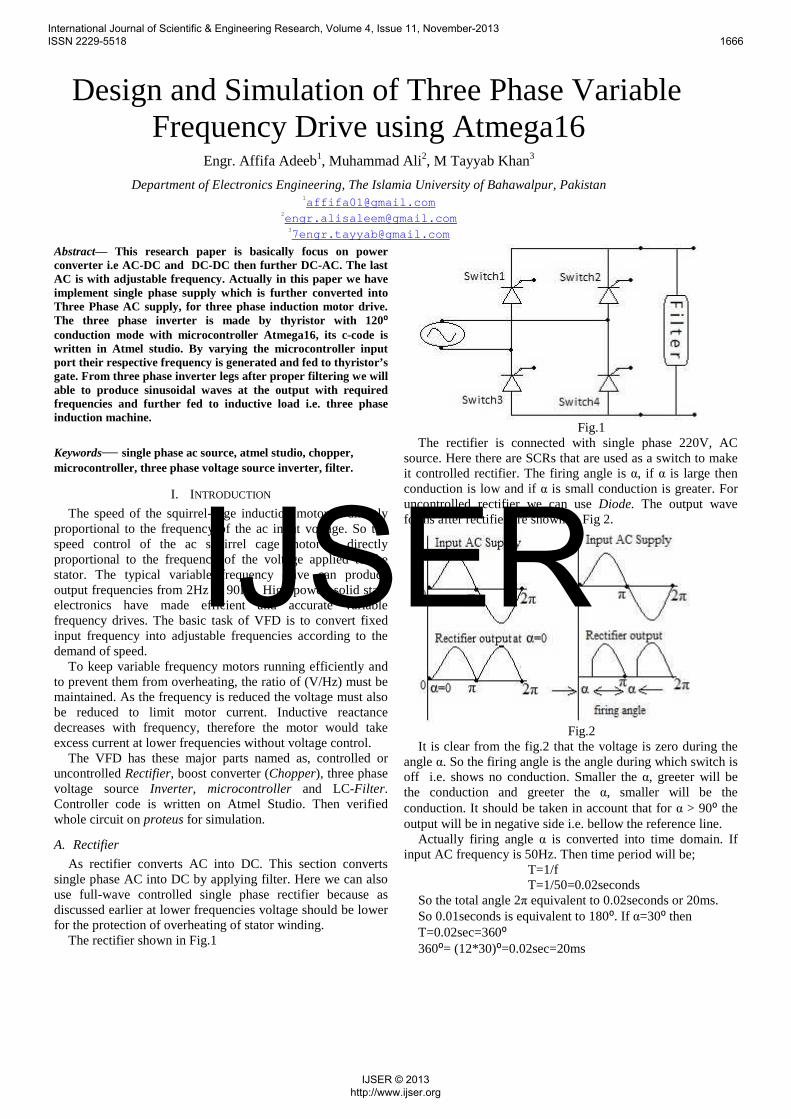
The rectifier shown in Fig.1
Fig.1 The rectifier is connected with single phase 220V, AC
source. Here there are SCRs that are used as a switch to make it controlled rectifier. The firing angle is α, if α is large then conduction is low and if α is small conduction is greater. For uncontrolled rectifier we can use Diode. The output wave forms after rectifier are shown in Fig 2.
Fig.2 It is clear from the fig.2 that the voltage is zero during the
angle α. So the firing angle is the angle during which switch is off i.e. shows no conduction. Smaller the α, greeter will be the conduction and greeter the α, smaller will be the conduction. It should be taken in account that for α > 90⁰ the output will be in negative side i.e. bellow the reference line.
Actually firing angle α is converted into time domain. If input AC frequency is 50Hz. Then time period will be;
T=1/f T=1/50=0.02seconds So the total angle 2π equivalent to 0.02seconds or 20ms. So 0.01seconds is equivalent to 180⁰. If α=30⁰ then T=0.02sec=360⁰ 360⁰= (12*30)⁰=0.02sec=20ms
International Journal of Scientific & Engineering Research, Volume 4, Issue 11, November-2013 ISSN 2229-5518 1666
IJSER © 2013 http://www.ijser.org
IJSER
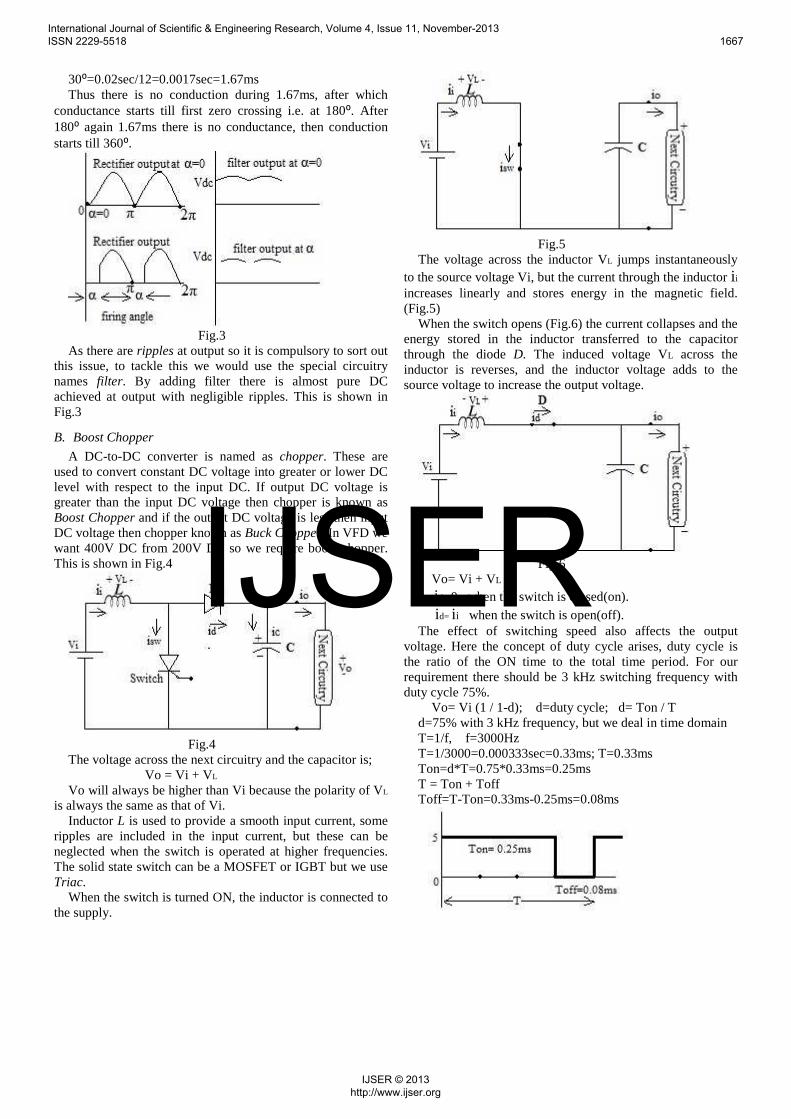
30⁰=0.02sec/12=0.0017sec=1.67ms Thus there is no conduction during 1.67ms, after which
conductance starts till first zero crossing i.e. at 180⁰. After 180⁰ again 1.67ms there is no conductance, then conduction starts till 360⁰.
Fig.3 As there are ripples at output so it is compulsory to sort out
this issue, to tackle this we would use the special circuitry names filter. By adding filter there is almost pure DC achieved at output with negligible ripples. This is shown in Fig.3
B. Boost Chopper
A DC-to-DC converter is named as chopper. These are used to convert constant DC voltage into greater or lower DC level with respect to the input DC. If output DC voltage is greater than the input DC voltage then chopper is known as Boost Chopper and if the output DC voltage is less then input DC voltage then chopper known as Buck Chopper. In VFD we want 400V DC from 200V DC so we require boost chopper. This is shown in Fig.4
Fig.4 The voltage across the next circuitry and the capacitor is; Vo = Vi + VL Vo will always be higher than Vi because the polarity of VL
is always the same as that of Vi. Inductor L is used to provide a smooth input current, some
ripples are included in the input current, but these can be neglected when the switch is operated at higher frequencies. The solid state switch can be a MOSFET or IGBT but we use Triac.
When the switch is turned ON, the inductor is connected to the supply.
Fig.5 The voltage across the inductor VL jumps instantaneously
to the source voltage Vi, but the current through the inductor i i increases linearly and stores energy in the magnetic field. (Fig.5)
When the switch opens (Fig.6) the current collapses and the energy stored in the inductor transferred to the capacitor through the diode D. The induced voltage VL across the inductor is reverses, and the inductor voltage adds to the source voltage to increase the output voltage.
Fig.6 Vo= Vi + VL
id= 0 when the switch is closed(on). id= i i when the switch is open(off). The effect of switching speed also affects the output
voltage. Here the concept of duty cycle arises, duty cycle is the ratio of the ON time to the total time period. For our requirement there should be 3 kHz switching frequency with duty cycle 75%.
Vo= Vi (1 / 1-d); d=duty cycle; d= Ton / T d=75% with 3 kHz frequency, but we deal in time domain T=1/f, f=3000Hz T=1/3000=0.000333sec=0.33ms; T=0.33ms Ton=d*T=0.75*0.33ms=0.25ms T = Ton + Toff Toff=T-Ton=0.33ms-0.25ms=0.08ms
International Journal of Scientific & Engineering Research, Volume 4, Issue 11, November-2013 ISSN 2229-5518 1667
IJSER © 2013 http://www.ijser.org
IJSER
This pulse modulated train is consciously triggering the Triac, to produce 3 kHz switching frequency. This pulse modulated train is produced from Atmega16 microcontroller.
C. Three-phase voltage source Inverter
A three-phase inverter is a device that changes DC input voltage (which is basically output of chopper) to a three-phase variable-frequency variable-voltage output. The input DC voltage can be from a DC source or rectified AC voltage. The circuit is shown in Fig.7.
Fig.7 It consists of six power switches with six associated
freewheeling diodes. The switches are opened and closed periodically in the proper sequence to produce the desired output waveform. The proper rate of switching determines the output frequency of the inverter. There are many switching modes which are possible to turn switches ON or off but here we use 120⁰ conduction mode i.e. each switch conducts for a period of 120⁰. In this mode only two switches are conducting at any time, it should be clear that if the upper switch is ON then its respective lower switch should be off, otherwise expensive power switches may burns out.
There is specific switching sequence which runs the inverter to produce particular waves at the output, shown in Fig.8
Fig.8 This switching pattern is produced by Atmaga16
microcontroller. i.e. On= 1, Off= 0 This whole switching pattern is equivalent to one time
period T, this time period is further split into six intervals. We can produce any frequency at output by proper adjusting the time between these time intervals. e.g. 50Hz, 52Hz, 54Hz up-
to 60Hz. But we can adjust frequencies according to our machine speed. Here we implement 50 to 60Hz frequencies.
For f= 60Hz, T=1/f; T=1/60=0.0167sec=16.7ms Thus whole time period is 16.7ms, we split this time into
six uniform intervals, so 1 interval= 16.7ms/6=2.73ms (2.73ms*6=16.7ms)
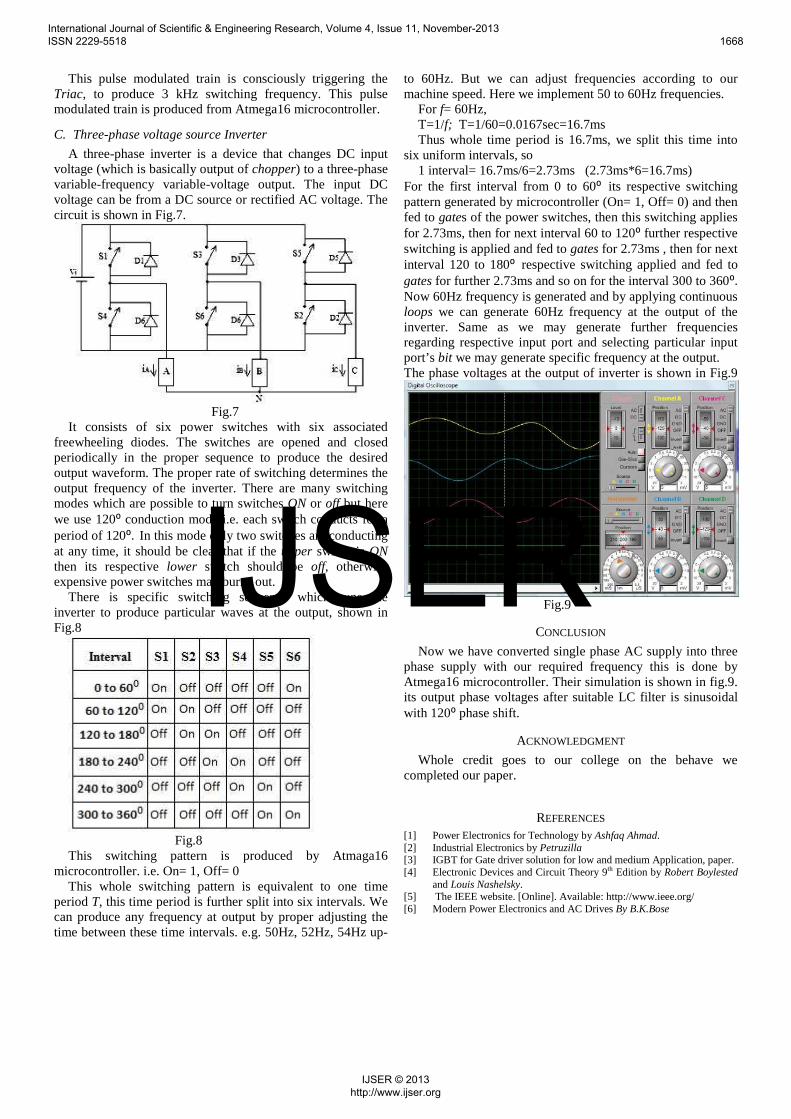
For the first interval from 0 to 60⁰ its respective switching pattern generated by microcontroller (On= 1, Off= 0) and then fed to gates of the power switches, then this switching applies for 2.73ms, then for next interval 60 to 120⁰ further respective switching is applied and fed to gates for 2.73ms , then for next interval 120 to 180⁰ respective switching applied and fed to gates for further 2.73ms and so on for the interval 300 to 360⁰. Now 60Hz frequency is generated and by applying continuous loops we can generate 60Hz frequency at the output of the inverter. Same as we may generate further frequencies regarding respective input port and selecting particular input port’s bit we may generate specific frequency at the output. The phase voltages at the output of inverter is shown in Fig.9
Fig.9
CONCLUSION
Now we have converted single phase AC supply into three phase supply with our required frequency this is done by Atmega16 microcontroller. Their simulation is shown in fig.9. its output phase voltages after suitable LC filter is sinusoidal with 120⁰ phase shift.
ACKNOWLEDGMENT
Whole credit goes to our college on the behave we completed our paper.
REFERENCES [1] Power Electronics for Technology by Ashfaq Ahmad. [2] Industrial Electronics by Petruzilla [3] IGBT for Gate driver solution for low and medium Application, paper. [4] Electronic Devices and Circuit Theory 9th Edition by Robert Boylested
and Louis Nashelsky. [5] The IEEE website. [Online]. Available: http://www.ieee.org/ [6] Modern Power Electronics and AC Drives By B.K.Bose
International Journal of Scientific & Engineering Research, Volume 4, Issue 11, November-2013 ISSN 2229-5518 1668
IJSER © 2013 http://www.ijser.org
IJSER