Embed Size (px)
Citation preview
IJSRD - International Journal for Scientific Research & Development| Vol. 5, Issue 07, 2017 | ISSN (online): 2321-0613
All rights reserved by www.ijsrd.com 256
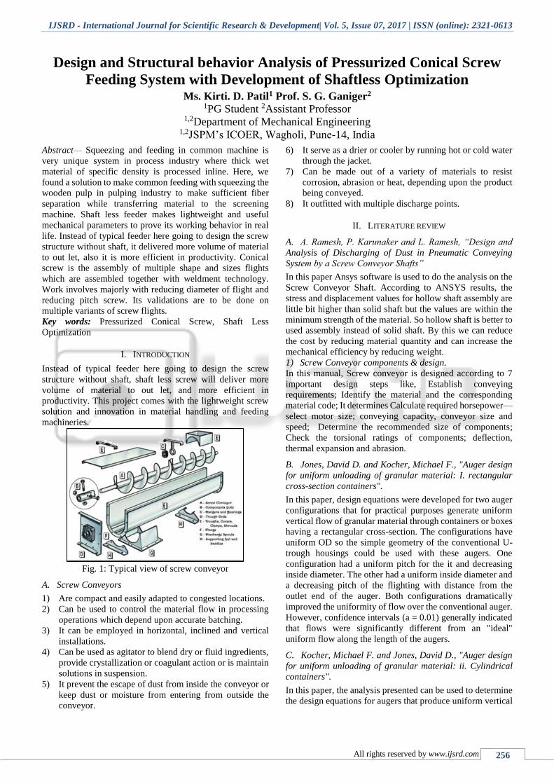
Design and Structural behavior Analysis of Pressurized Conical Screw
Feeding System with Development of Shaftless Optimization Ms. Kirti. D. Patil1 Prof. S. G. Ganiger2
1PG Student 2Assistant Professor
1,2Department of Mechanical Engineering 1,2JSPM’s ICOER, Wagholi, Pune-14, India
Abstract— Squeezing and feeding in common machine is
very unique system in process industry where thick wet
material of specific density is processed inline. Here, we
found a solution to make common feeding with squeezing the
wooden pulp in pulping industry to make sufficient fiber
separation while transferring material to the screening
machine. Shaft less feeder makes lightweight and useful
mechanical parameters to prove its working behavior in real
life. Instead of typical feeder here going to design the screw
structure without shaft, it delivered more volume of material
to out let, also it is more efficient in productivity. Conical
screw is the assembly of multiple shape and sizes flights
which are assembled together with weldment technology.
Work involves majorly with reducing diameter of flight and
reducing pitch screw. Its validations are to be done on
multiple variants of screw flights.
Key words: Pressurized Conical Screw, Shaft Less
Optimization
I. INTRODUCTION
Instead of typical feeder here going to design the screw
structure without shaft, shaft less screw will deliver more
volume of material to out let, and more efficient in
productivity. This project comes with the lightweight screw
solution and innovation in material handling and feeding
machineries.
Fig. 1: Typical view of screw conveyor
A. Screw Conveyors
1) Are compact and easily adapted to congested locations.
2) Can be used to control the material flow in processing
operations which depend upon accurate batching.
3) It can be employed in horizontal, inclined and vertical
installations.
4) Can be used as agitator to blend dry or fluid ingredients,
provide crystallization or coagulant action or is maintain
solutions in suspension.
5) It prevent the escape of dust from inside the conveyor or
keep dust or moisture from entering from outside the
conveyor.
6) It serve as a drier or cooler by running hot or cold water
through the jacket.
7) Can be made out of a variety of materials to resist
corrosion, abrasion or heat, depending upon the product
being conveyed.
8) It outfitted with multiple discharge points.
II. LITERATURE REVIEW
A. A. Ramesh, P. Karunaker and L. Ramesh, “Design and
Analysis of Discharging of Dust in Pneumatic Conveying
System by a Screw Conveyor Shafts”
In this paper Ansys software is used to do the analysis on the
Screw Conveyor Shaft. According to ANSYS results, the
stress and displacement values for hollow shaft assembly are
little bit higher than solid shaft but the values are within the
minimum strength of the material. So hollow shaft is better to
used assembly instead of solid shaft. By this we can reduce
the cost by reducing material quantity and can increase the
mechanical efficiency by reducing weight.
1) Screw Conveyor components & design.
In this manual, Screw conveyor is designed according to 7
important design steps like, Establish conveying
requirements; Identify the material and the corresponding
material code; It determines Calculate required horsepower—
select motor size; conveying capacity, conveyor size and
speed; Determine the recommended size of components;
Check the torsional ratings of components; deflection,
thermal expansion and abrasion.
B. Jones, David D. and Kocher, Michael F., "Auger design
for uniform unloading of granular material: I. rectangular
cross-section containers".
In this paper, design equations were developed for two auger
configurations that for practical purposes generate uniform
vertical flow of granular material through containers or boxes
having a rectangular cross-section. The configurations have
uniform OD so the simple geometry of the conventional U-
trough housings could be used with these augers. One
configuration had a uniform pitch for the it and decreasing
inside diameter. The other had a uniform inside diameter and
a decreasing pitch of the flighting with distance from the
outlet end of the auger. Both configurations dramatically
improved the uniformity of flow over the conventional auger.
However, confidence intervals (a = 0.01) generally indicated
that flows were significantly different from an "ideal"
uniform flow along the length of the augers.
C. Kocher, Michael F. and Jones, David D., "Auger design
for uniform unloading of granular material: ii. Cylindrical
containers".
In this paper, the analysis presented can be used to determine
the design equations for augers that produce uniform vertical
Design and Structural behavior Analysis of Pressurized Conical Screw Feeding System with Development of Shaftless Optimization
(IJSRD/Vol. 5/Issue 07/2017/063)
All rights reserved by www.ijsrd.com 257
flow of granular material through containers with cylindrical
cross-sections. The augers so designed have a constant
outside diameter and a variable root or shaft diameter. They
could be used to convert a batch-in-bin dryer to a continuous
flow dryer. The analysis is an extension of the work of Jones
and Kocher (/995) who designed and tested such an auger for
containers of rectangular cross-section, and determined flow
to be uniform for practical purposes. The analysis follows the
same concept used by Shivvers (1973) to develop augers with
variable outside diameter to provide uniform vertical flow of
granular material through containers with cylindrical cross-
section.
D. GEC NO. 8, “Design and Construction of Continuous
Flight Auger (CFA) Piles”.
This document is to develop a state-of-the-practice manual
for the design and construction of continuous flight auger
(CFA) piles, including those piles commonly referred to as
augered cast-in-place (ACIP) piles, drilled displacement
(DD) piles, and screw piles. In this document allowable stress
design procedure is presented as resistance factors have not
yet been calibrated for CFA piles for a Load Resistance
Factored Design approach. The intended audience for this
document is engineers and construction specialists involved
in the design, construction, and contracting of foundation
elements for transportation structures.
E. Marco Bortolamasi, Johannes Fottner, “Design and
sizing of screw feeders”.
This paper describes the screw feeders are devices suitable
for handling a wide variety of materials that have good
flowability characteristics. The screw feeder has a helicoidal
surface fitted on a shaft that rotates inside a fixed tube. The
material comes out of the silo is pushed by the helicoid flight
in the direction of transport. The advantages of the screw
feeder include the possibility of having different openings,
each with its own shut-off organ for unloading the material.
F. Alan W. Roberts, Emeritus Professor and Director,
“Design considerations and performance evaluation of screw
conveyors”.
This paper describes the performance of screw conveyors is
significantly influenced by the vortex motion of the bulk solid
being conveyed. The vortex motion, together with the degree
of fill, govern the volumetric efficiency and, hence, the
throughput. This, in turn, influences the torque, power and
conveying efficiency. The flow properties of the bulk
material being conveyed are shown to have a significant
influence on the performance.
III. PROBLEM STATEMENT
Making of plug screw with one piece is manufacturability
difficult process.
Now nonstandard and multidimensional screws
required to obtain various output in various requirements. So
full feel these, we need to design new conical screw with
flights weldment assembly and shaftless work, to helping out
reducing weight and reducing unwanted load parameters.
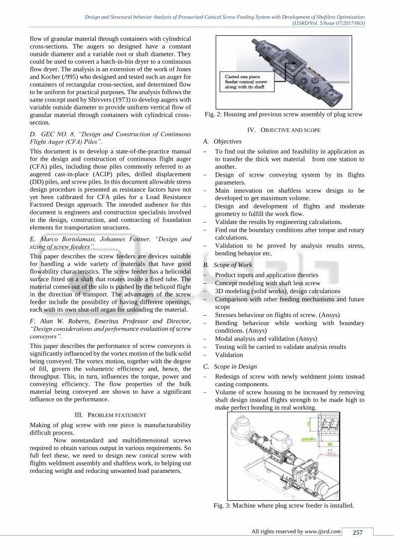
Fig. 2: Housing and previous screw assembly of plug screw
IV. OBJECTIVE AND SCOPE
A. Objectives
To find out the solution and feasibility in application as
to transfer the thick wet material from one station to
another.
Design of screw conveying system by its flights
parameters.
Main innovation on shaftless screw design to be
developed to get maximum volume.
Design and development of flights and moderate
geometry to fulfill the work flow.
Validate the results by engineering calculations.
Find out the boundary conditions after torque and rotary
calculations.
Validation to be proved by analysis results stress,
bending behavior etc.
B. Scope of Work
Product inputs and application theories
Concept modeling with shaft less screw
3D modeling (solid works), design calculations
Comparison with other feeding mechanisms and future
scope
Stresses behaviour on flights of screw. (Ansys)
Bending behaviour while working with boundary
conditions. (Ansys)
Modal analysis and validation (Ansys)
Testing will be carried to validate analysis results
Validation
C. Scope in Design
Redesign of screw with newly weldment joints instead
casting components.
Volume of screw housing to be increased by removing
shaft design instead flights strength to be made high to
make perfect bonding in real working.
Fig. 3: Machine where plug screw feeder is installed.
Design and Structural behavior Analysis of Pressurized Conical Screw Feeding System with Development of Shaftless Optimization
(IJSRD/Vol. 5/Issue 07/2017/063)
All rights reserved by www.ijsrd.com 258
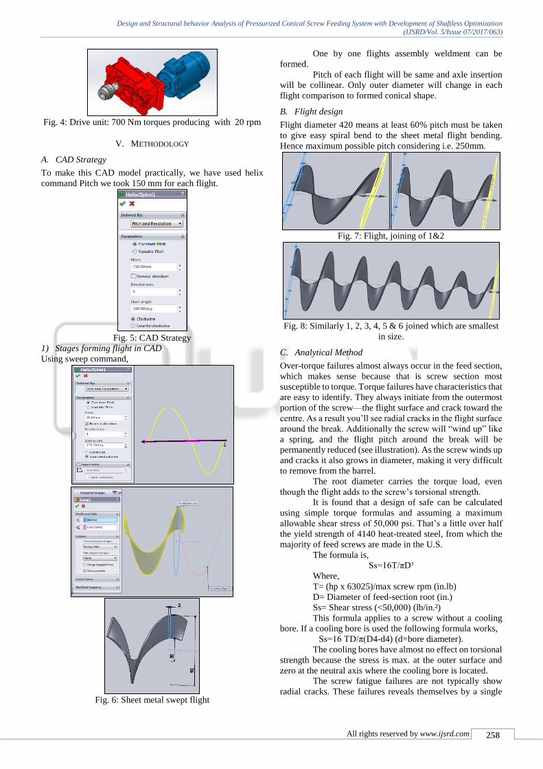
Fig. 4: Drive unit: 700 Nm torques producing with 20 rpm
V. METHODOLOGY
A. CAD Strategy
To make this CAD model practically, we have used helix
command Pitch we took 150 mm for each flight.
Fig. 5: CAD Strategy
1) Stages forming flight in CAD
Using sweep command,
Fig. 6: Sheet metal swept flight
One by one flights assembly weldment can be
formed.
Pitch of each flight will be same and axle insertion
will be collinear. Only outer diameter will change in each
flight comparison to formed conical shape.
B. Flight design
Flight diameter 420 means at least 60% pitch must be taken
to give easy spiral bend to the sheet metal flight bending.
Hence maximum possible pitch considering i.e. 250mm.
Fig. 7: Flight, joining of 1&2
Fig. 8: Similarly 1, 2, 3, 4, 5 & 6 joined which are smallest
in size.
C. Analytical Method
Over-torque failures almost always occur in the feed section,
which makes sense because that is screw section most
susceptible to torque. Torque failures have characteristics that
are easy to identify. They always initiate from the outermost
portion of the screw—the flight surface and crack toward the
centre. As a result you’ll see radial cracks in the flight surface
around the break. Additionally the screw will “wind up” like
a spring, and the flight pitch around the break will be
permanently reduced (see illustration). As the screw winds up
and cracks it also grows in diameter, making it very difficult
to remove from the barrel.
The root diameter carries the torque load, even
though the flight adds to the screw’s torsional strength.
It is found that a design of safe can be calculated
using simple torque formulas and assuming a maximum
allowable shear stress of 50,000 psi. That’s a little over half
the yield strength of 4140 heat-treated steel, from which the
majority of feed screws are made in the U.S.
The formula is,
Ss=16T/πD³
Where,
T= (hp x 63025)/max screw rpm (in.lb)
D= Diameter of feed-section root (in.)
Ss= Shear stress (<50,000) (lb/in.²)
This formula applies to a screw without a cooling
bore. If a cooling bore is used the following formula works,
Ss=16 TD/π(D4-d4) (d=bore diameter).
The cooling bores have almost no effect on torsional
strength because the stress is max. at the outer surface and
zero at the neutral axis where the cooling bore is located.
The screw fatigue failures are not typically show
radial cracks. These failures reveals themselves by a single
Design and Structural behavior Analysis of Pressurized Conical Screw Feeding System with Development of Shaftless Optimization
(IJSRD/Vol. 5/Issue 07/2017/063)
All rights reserved by www.ijsrd.com 259
crack that goes all the way through the screw. In addition,
these failures don’t result in the “wind-up” effect or a pitch
reduction.
Bending occured either from the side forces of the
polymer exerts on the screw, or from misalignment of the
barrel. Bending by either mechanism is termed “reversed
bending.” Think of the rapid failure caused when you break a
wire between your fingers by flexing it back and forth.
In order for the internal barrel pressures to cause a
screw break, the screw/barrel must first be worn enough to
provide the clearance necessary for the bending to occur. This
may take a long time, but once sufficient clearance is present,
breakage quickly follows. I have covered this type of
localized wear, called wedging, in previous columns .The
screw is also under torsional load from the drive, adding to
the overall stress, since both bending and torsional stresses
are at their maximum on the outer surface of the screw. With
the combination of the reversible bending stress and torsional
stress, failure will occur in very few cycles after the critical
stress is reached at the surface. That is typically at about 40%
of the normal tensile strength, meaning reversed bending
reduces the strength to about half the steel’s specification.
Bending failures due to barrel alignment are similar
but can occur sooner because it’s not necessary to wait for the
screw and barrel to wear. Interestingly, bending failures
usually occur in the strongest sections of the screw, because
that’s where it takes the highest force to bend it, with the
resulting highest stress at the flight surface. When a screw
breaks in one of its thickest or strongest sections, it’s
extremely unlikely that it was an over-torque situation alone.
Considering bending beam installed on flights
surface to save thickens of the sheet metal.
Beam is the main support against bending pushing
forces coming by flowing material.
1) Design of Anti bending beam on flight
Need of the component: anti bending stiffness for sheet metal
body of flight is majorly can be considered at joint forming
at two flight assembly , so to make feasible weldment joint
between two flights its effective solution to install beam
structure .
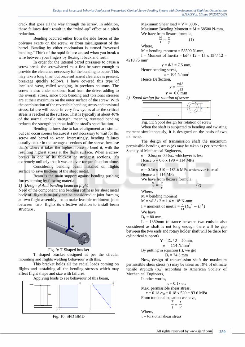
Fig. 9: T-Shaped bracket
T shaped bracket designed as per the circular
mounting and flights welding behaviour with this.
This bracket holds all the radial loads coming on
flights and sustaining all the bending stresses which may
affect flight shape and size with failures.
Applying loads to see behaviour of this beam,
Fig. 10: SFD BMD
Maximum Shear load = V = 300N,
Maximum Bending Moment = M = 58500 N-mm,
We have from flexure formula, M
I=
σ
y (1)
Where,
M = bending moment = 58500 N-mm,
I = Moment of Inertia = bd3 / 12 = 15 x 153 / 12 =
4218.75 mm4
y = d/2 = 7.5 mm,
Hence bending stress,
σ = 104 N/mm2
Hence Deflection,
y = wL3
3EI
y = 0.8 mm 2) Spool design for rotation of screw
Fig. 11: Spool design for rotation of screw
When the shaft is subjected to bending and twisting
moment simultaneously, it is designed on the basis of two
moments.
The design of transmission shaft the maximum
permissible bending stress (σ) may be taken as per American
Society of Mechanical Engineers,
σ = 0.6σel or 0.36σut whichever is less
Hence σ = 0.6 x 190 = 114 MPa
Or
σ = 0.36 x 510 = 183.6 MPa whichever is small
Hence σ = 114 MPa
We have from flexure formula, 𝑀
𝐼=
𝜎
𝑦 (2)
Where,
M = bending moment
M = wL2 / 2 = 1.4 x 10⁶ N-mm
I = moment of inertia = 𝜋
64(𝐷0
4 − 𝐷𝑖4)
We have
Do = 80 mm,
L = 1350mm (distance between two ends is also
considered as shaft is not long enough there will be gap
between the two ends and rotary holder shaft will be there for
cylindrical support)
Y = Do / 2 = 40mm,
𝜎 = 114 N/mm2
By putting in equation (i), we get
Di = 74.5 mm
Now, design of transmission shaft the maximum
permissible shear stress (τ) may be taken as 18% of ultimate
tensile strength (σut) according to American Society of
Mechanical Engineers,
In other words,
τ = 0.18 σut
Max. permissible shear stress,
τ = 0.18 σut = 0.18 x 520 = 93.6 MPa
From torsional equation we have, 𝑇
𝑗=
𝜏
𝑅
Where,
τ = torsional shear stress
Design and Structural behavior Analysis of Pressurized Conical Screw Feeding System with Development of Shaftless Optimization
(IJSRD/Vol. 5/Issue 07/2017/063)
All rights reserved by www.ijsrd.com 260
T = torque acting on the shaft
j = polar moment of inertia
R = Distance from neutral axis to outermost fibre =
D0/2....
Where D is diameter of the shaft = 40 mm
We know that, for solid circular shaft, polar moment
inertia (j) is given by,
𝑗 = 𝜋
32(𝐷0
4 − 𝐷𝑖4)
J = 1.0 x 106 mm4
Now, the Shear stress is
τ = 0.3 σel = 0.3 x 205 = 61.5 MPa
Hence,
Torque acting on shaft
T= 1.533 x 10⁶ Nmm
According to maximum shear stress theory,
τmax = 16𝐷0
𝜋(𝐷04−𝐷𝑖
4)𝑇𝑒
Where,
Te = 1.713 x 10³ N/mm2
Te = √(M2+T2)
Hence Maximum shear stress,
τmax =68.7 N/m2
According to Macaulay’s Method, Maximum
Deflection is given by,
𝑦 = 𝑤𝐿2
8𝐸𝐼
Hence, Maximum Deflection is
Y = 3.42 x 10³
D. Assembly features
Antibending beam installed as requirement in machine is
given.
One by one flights assembly weldment can be
formed.
Pitch of each flight will be same and axle insertion
will be collinear. Only outer diameter will change in each
flight comparison to formed conical shape.
Fig. 12: Actual conical vessel
Assembled in linear pattern with pitch dimensions
maintained now it will get cut in shape after welded all the
beams in line along with every flight joint. Reducing flight
sizes, to accommodate into conical shape vessel.
Fig. 13: Screw assembly installed inside vessel
Fig. 14: Screw assembly
Fig. 15: Beams welded on spool beam
Fig. 16: Screw assembly overall dimensions
E. Numerical / Computational Method
1) Assembly simulation on CAE
Applying all boundary condition on all flights
simultaneously,
Analysis on stress and deformation results to validate
design ,
If deflection found positive (beyond zero value) structure
of flights joints will get changed.
Again analysis on rework will be included.
Validation on spool less flighting will evaluated
which will help to get conclusion.
Fig. 17: Meshed model
Fig. 18: Meshed model graph
Fig. 19: 3D model

Design and Structural behavior Analysis of Pressurized Conical Screw Feeding System with Development of Shaftless Optimization
(IJSRD/Vol. 5/Issue 07/2017/063)
All rights reserved by www.ijsrd.com 261
Fig. 20: 3D model graph
Fig. 21: Boundary conditions applied
Fig. 22: Boundary conditions applied graph
Fig. 23: Permanent deformation is negligible
VI. MATERIAL SELECTION
Material to be used is AISI316 as pressure vessel
manufacturing and testing occurs in pulping and fluid
medium so other special purpose machines and supporting
machineries are also get contact with wet medium hence here
anti corrosive material to be applied everywhere.
Table 1: AISI316 grade of stainless steel
No limitations on thickness in relation to brittle fracture apply
to stainless steel; the limitations for carbon steel are not
applicable due to the superior toughness of stainless steel.
The austenitic stainless steel grades do not show a ductile-
brittle impact strength transition as temperatures are lowered.
Stainless steels can absorb considerable impact without
fracturing due to their excellent ductility and their strain-
hardening characteristics.
This type of plate has a thickness of specifically
designed with high strength wear resistant material formed by
a special deposition welding method over laying mild carbon
steel.
VII. EXPERIMENTATION & VALIDATION
By putting strain gauges on the surface of this unique screw,
external forces will be applied by hydro-pneumatic loads or
actuators and equivalent strains and stresses will be the output
of testing machine.
A. Experimental Setup
Fig. 24: Actual machine view
This is the on which actual testing is to be carried out. The
name of machine is Semi Automated Strain Gauge Output
Analogger. Strain gauges are fixed on testing specimen by
soldering operation. After loading machine gives strain
developed into the specimen. By using stress strain relation
stress induced in component is calculated. Pneumatic or
Hydraulic bar are used for loading.
Fig. 25: Blank machine setup
This is the photograph of blank machine setup.
These are some fixtures are shown in photograph. After
fixing our specimen into this fixture actual testing is done.
The blue pipes are seen in this picture are pneumatic
pipelines. The various types of fixtures are available in lab.
According to our requirement fixtures can be manufactured
also.
Design and Structural behavior Analysis of Pressurized Conical Screw Feeding System with Development of Shaftless Optimization
(IJSRD/Vol. 5/Issue 07/2017/063)
All rights reserved by www.ijsrd.com 262
B. Processing testing on component
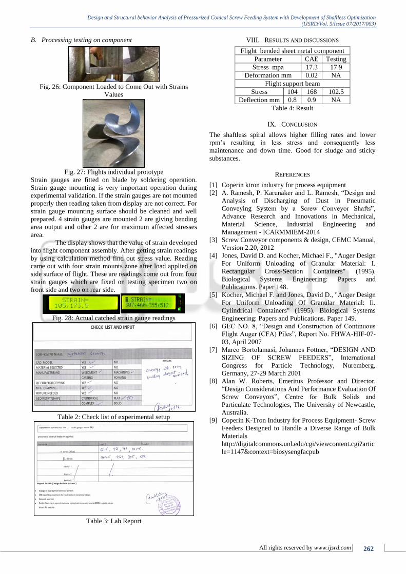
Fig. 26: Component Loaded to Come Out with Strains
Values
Fig. 27: Flights individual prototype
Strain gauges are fitted on blade by soldering operation.
Strain gauge mounting is very important operation during
experimental validation. If the strain gauges are not mounted
properly then reading taken from display are not correct. For
strain gauge mounting surface should be cleaned and well
prepared. 4 strain gauges are mounted 2 are giving bending
area output and other 2 are for maximum affected stresses
area.
The display shows that the value of strain developed
into flight component assembly. After getting strain readings
by using calculation method find out stress value. Reading
came out with four strain mounts zone after load applied on
side surface of flight. These are readings come out from four
strain gauges which are fixed on testing specimen two on
front side and two on rear side.
Fig. 28: Actual catched strain gauge readings
Table 2: Check list of experimental setup
Table 3: Lab Report
VIII. RESULTS AND DISCUSSIONS
Flight bended sheet metal component
Parameter CAE Testing
Stress mpa 17.3 17.9
Deformation mm 0.02 NA
Flight support beam
Stress 104 168 102.5
Deflection mm 0.8 0.9 NA
Table 4: Result
IX. CONCLUSION
The shaftless spiral allows higher filling rates and lower
rpm’s resulting in less stress and consequently less
maintenance and down time. Good for sludge and sticky
substances.
REFERENCES
[1] Coperin ktron industry for process equipment
[2] A. Ramesh, P. Karunaker and L. Ramesh, “Design and
Analysis of Discharging of Dust in Pneumatic
Conveying System by a Screw Conveyor Shafts”,
Advance Research and Innovations in Mechanical,
Material Science, Industrial Engineering and
Management - ICARMMIEM-2014
[3] Screw Conveyor components & design, CEMC Manual,
Version 2.20, 2012
[4] Jones, David D. and Kocher, Michael F., "Auger Design
For Uniform Unloading of Granular Material: I.
Rectangular Cross-Section Containers" (1995).
Biological Systems Engineering: Papers and
Publications. Paper 148.
[5] Kocher, Michael F. and Jones, David D., "Auger Design
For Uniform Unloading Of Granular Material: Ii.
Cylindrical Containers" (1995). Biological Systems
Engineering: Papers and Publications. Paper 149.
[6] GEC NO. 8, “Design and Construction of Continuous
Flight Auger (CFA) Piles”, Report No. FHWA-HIF-07-
03, April 2007
[7] Marco Bortolamasi, Johannes Fottner, “DESIGN AND
SIZING OF SCREW FEEDERS”, International
Congress for Particle Technology, Nuremberg,
Germany, 27-29 March 2001
[8] Alan W. Roberts, Emeritus Professor and Director,
“Design Considerations And Performance Evaluation Of
Screw Conveyors”, Centre for Bulk Solids and
Particulate Technologies, The University of Newcastle,
Australia.
[9] Coperin K-Tron Industry for Process Equipment- Screw
Feeders Designed to Handle a Diverse Range of Bulk
Materials
http://digitalcommons.unl.edu/cgi/viewcontent.cgi?artic
le=1147&context=biosysengfacpub