Embed Size (px)
Citation preview
Design and Test on Underwater Automatic Welding Equipment in High-Pressure
Chamber
Linlin Zhang Institute of Oceanographic Instrumentation, Shandong
Academy of Science QingDao, China
Ziqiang Yin Institute of Oceanographic Instrumentation, Shandong
Academy of Science QingDao, China
Zhenlin Yang Institute of Oceanographic Instrumentation, Shandong
Academy of Science QingDao, China
Haixin Li Institute of Oceanographic Instrumentation, Shandong
Academy of Science QingDao, China
Xin Yuan Institute of Oceanographic Instrumentation, Shandong
Academy of Science QingDao, China
Abstract— In order to realize underwater automatic welding in deep water environment, an automatic welding equipment, which is composed of truss structure, welding mechanism and mobile walking mechanism was designed and tested in the recent research. The bent fatigue strength check was carried on the driving part of the system. High-pressure chamber was used to simulate the high pressure deep water environment. Test of the automatic welding equipment test was conducted by the flux core arc welding(FCAW) in pressure chamber under hydrostatic pressure about 30-200 meters of water depth. Arc voltage and welding current were recorded during the welding tests. Visual inspection was also conducted on the weld. According to the above tests results, it was shown that the automatic welding equipment works stably and credibly, and the apperance of weld was excellence. It was concluded that this equipment can satisfy the requirements of underwater automatic welding in high-pressure underwater environment.
Keywords- underwater welding; automatic welding; hydrostatic pressure; strength check; welding test
I. INTRODUCTION
The underwater welding technology is necessary for the exploit of ocean resources and underwater engineering, for example, the construction, maintenance and transformation of offshore continental drilling platforms. A convenient and reliable method was provided by this technology in many aspects, such as seabed pipe installation, damage remedying, the installation and service of underwater steel structure at sea[1-4].
For a long period, the automatic level of underwater welding was not high in our country, the work of
underwater welding was completed by manual welding of welder-diver. Diving medical research considered that the depth of conventional air diving should not be more than 60 m, the depth of conventional helium-oxygen diving should be 60-150 m (less than 120 m was appropriate). For the greater diving depth of deep-sea diving task, saturation diving technique should be accepted. Thus, manual welding of welder-diver was limited to human extreme diving depth, such as more dangerous, less effective working hours and inefficiency. Furthermore, the quality of underwater welded joint was affected by the technological level of welder-diver and welding techniques[5,6]. In order to solve the above-mentioned problem, the advanced automatic level of underwater welding system was urgently needed to develop for ensuring the quality of underwater welding, reducing production cost, enhancing productivity and breaking out the limited depth of underwater welding. Welding equipment transformed from manual welding to underwater automatic welding. The efficient and low-cost underwater welding was achieved[7].
In order to study the automatic welding technology under larger deep-water environment, the underwater automatic welding system was designed in this paper. The underwater automatic welding test was completed in simulation of high-pressure environment. It can satisfy the requirement of welding in special underwater environment. The equipment was tested in pressure chamber under pressure equals to 30-200 meters of water depth.
International Conference on Chemical, Material and Food Engineering (CMFE-2015)
© 2015. The authors - Published by Atlantis Press 885
II. TEST SYSTEM DESIGN SCHEME OF UNDERWATER
AUTOMATIC WELDING
A. The component of test system of underwater automatic welding
The test system of underwater welding was divided into two types: vertical and horizontal. The test system included the gas storage pressure chamber, the working pressure chamber, the pressure chamber locking system and the welding executive system[8]. This kind of system had a huge volume, complex structure and inconvenient operation. Furthermore, it was difficult to realize the underwater all-position welding of any welding seam. In order to simulate the underwater environment and relative water depth, a pressure chamber was required to be designed. The maximum simulated water depth was 200m. Considering that the horizontal pressure vessel need to drainage before opening hatches each time and the operation was inconvenient, the pressure chamber used vertical pressure vessel structure. Compared with the horizontal structure, vertical structure can simplify the seal. The lower part of inside container was filled with water and the upper part was gas. Therefore, quick-opening dome of the container just required gas sealing, which reduced the difficulty of sealing.
Automatic welding equipment was the basic mechanism for achieving high pressure underwater welding. It was located in the pressure chamber. The pressure chamber and the automatic welding equipment are shown in Figure 1.
Figure 1. The pressure chamber and automatic welding equipment
B. The operating principle of automatic welding equipment
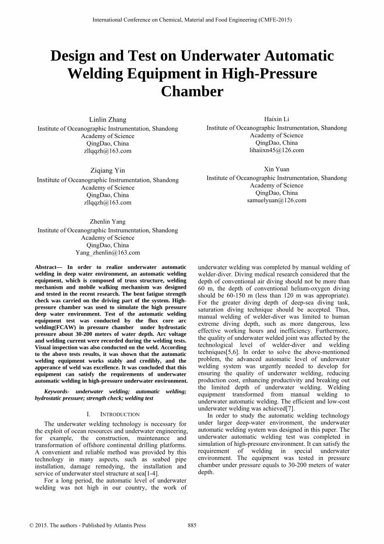
The component of automatic welding equipment is shown in Figure 2. The automatic welding equipment was composed of truss structure, welding mechanism and mobile walking mechanism. The truss structure was composed of the cubic installation frame. The welding mechanism was composed of welding torch, hydraulic motor and wire feeder. Mobile walking mechanism was consisted of two sets of gear racks, underwater motor, reducer, guide rail, slider and linear guideway. The first set of racks was fixed on the frame, the gear meshed with the racks was connected with the underwater motor and the
slider. The slider was linked with two orthogonal guider and the second set of gear. As connected to the welding mechanism, the second set of gear was also connected with the underwater motor through the reducer. The second guide rail parallel to the second set of racks was connected with the racks through a slider in each end. Both sliders could move on the linear guideways, which were fixed on the frame.
As shown in figure 2, the first set of gear driven by X direction underwater motor meshed with the racks to achieve linear motion. The connected slider went along with the guide rail, which was driven by gear, at the same time, the slider drove another guide rail, making another guide rail went through the linear slide by the ends of sliders. Namely, the second set of rack was driven by the ends of sliders along the linear slide for linear motion. The welding mechanism was driven by the first underwater motor along the X axis rectilinearly. After the motor in Y direction was decelerated by planetary reducer, the drive gear of the reducer output shaft and the rack were meshed to achieve linear motion. The welding mechanism driven by underwater motor could move in a straight line along the Y direction.
underwater motor
truss structure
guide rail
reducer
linear guideway
underwater motor wire feeder
welding torch
slider
hydraulic motor
Figure 2. Automatic welding equipment
Mobile mechanism could realize welding mechanism not only linear motion along the X axis and Y axis direction respectively, but also along the curve movement of the motion synthesis of X axis and Y axis. All kinds of relative motion were accomplished between the welding torch and the weldment. Meanwhile, due to the truss structure with a cubic frame, flat welding and vertical welding could be realized in different welding position by rotating the truss structure.
The wire feeder was driven by a hydraulic motor in welding mechanism. Compared with other transmission modes, the hydraulic motor had the following advantages:
1) With the same volume, the hydraulic motor could produce more power than the electric motor. Therefore, under the same power output, the hydraulic motor could be with smaller volume and less weight than the electric motor. The volume and weight of the hydraulic motor accounted for only 12% of electric motor with the same power output[9].
2) For hydraulic transmission, stepless speed change could be achieved in a wide range (speed ratio up to 1:
886
2000). It also could be adjusted during the run of hydraulic equipment[10,11].
3) Hydraulic motor was self-sealing and it did not need further secondary sealed.
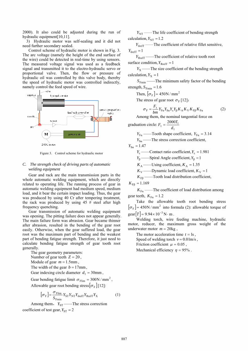
Control scheme of hydraulic motor is shown in Fig. 3. The arc voltage (namely the height of the end surface of the wire) could be detected in real-time by using sensors. The measured voltage signal was used as a feedback signal and transmitted it to the electro-hydraulic servo or proportional valve. Then, the flow or pressure of hydraulic oil was controlled by this valve body, thereby the speed of hydraulic motor was controlled indirectly, namely control the feed speed of wire.
Figure 3. Control scheme for hydraulic motor
C. The strength check of driving parts of automatic welding equipment
Gear and rack are the main transmission parts in the whole automatic welding equipment, which are directly related to operating life. The running process of gear in automatic welding equipment had medium speed, medium load, and it bear the certain impact loading. Thus, the gear was produced by using 40 Cr after tempering treatment, the rack was produced by using 45 # steel after high frequency quenching.
Gear transmission of automatic welding equipment was opening. The pitting failure does not appear generally. The main failure form was abrasion. Gear became thinner after abrasion, resulted in the bending of the gear root easily. Otherwise, when the gear suffered load, the gear root was the maximum part of bending and the weakest part of bending fatigue strength. Therefore, it just need to calculate bending fatigue strength of gear tooth root generally.
The gear geometry parameters: Number of gear teeth 20Z , Module of gear mm5.1m , The width of the gear mm17b , Gear indexing circle diameter mm301 d ,
Gear bending fatigue limit 2Flim mm/N300 ,
Allowable gear root bending stress F [12]:
XRrelTδrelTNTSTFmin
FlimF YYYYY
S
(1)
Among them, STY ——The stress correction
coefficient of test gear, 2ST Y
NTY ——The life coefficient of bending strength
calculation, 2.1NT Y
δrelTY ——The coefficient of relative fillet sensitive,
1δrelT Y
RrelTY ——The coefficient of relative tooth root
surface condition, 1RrelT Y
XY ——The size coefficient of the bending strength
calculation, 1X Y
FminS ——The minimum safety factor of the bending
strength, 6.1Fmin S
Then, 2F mm/N450
The stress of gear root F [12]:
FαFβVAβεSαFαt
F KKKKYYYYbm
F (2)
Among them, the nominal tangential force on
graduation circle:1
1t
2000
d
TF
FαY ——Tooth shape coefficient, 14.3Fα Y
SαY ——The stress correction coefficient,
47.1Sα Y
εY ——Contact ratio coefficient, 981.1ε Y
βY ——Spiral Angle coefficient, 1β Y
AK ——Using coefficient, 35.1A K
VK ——Dynamic load coefficient, 1V K
FβK ——Tooth load distribution coefficient,
169.1Fβ K
FαK ——The coefficient of load distribution among
gear teeth, 2.1Fα K Take the allowable tooth root bending stress
2F mm/N450 into formula (2): allowable torque of
gear mN1094.9 3 T . Welding torch, wire feeding machine, hydraulic
motor, reducer, the maximum gross weight of the underwater motor kg20m ,
The motor acceleration time s1t , Speed of welding torch m/s01.0v , Friction coefficient 05.0 , Mechanical efficiency %95 .
887
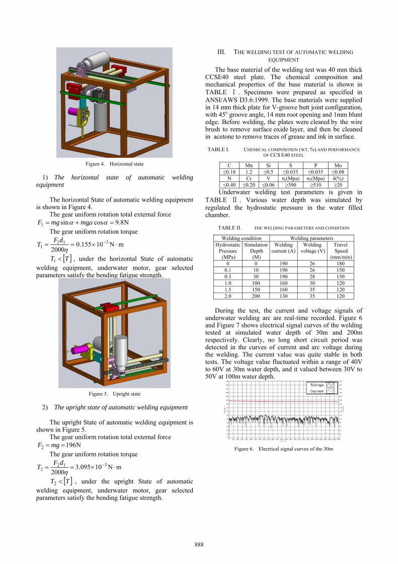
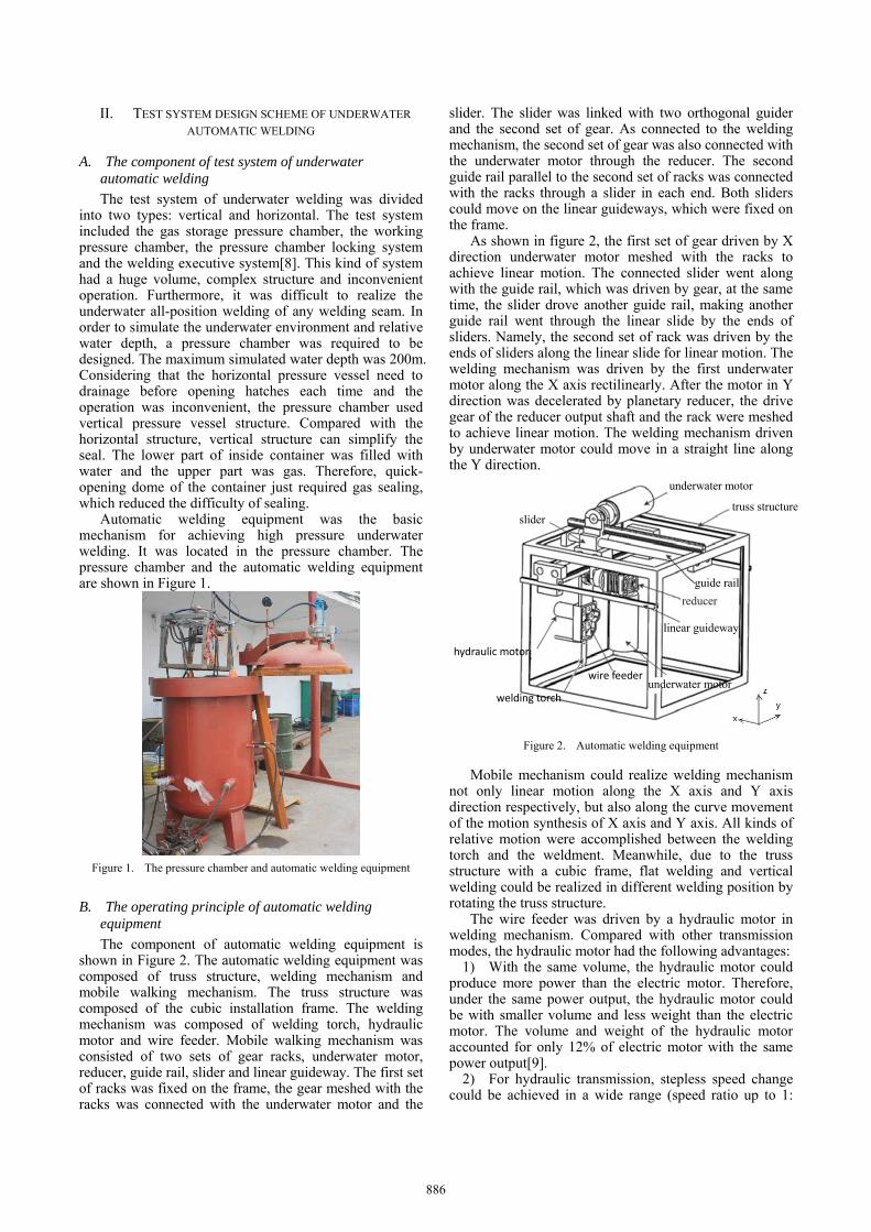
Figure 4. Horizontal state
1) The horizontal state of automatic welding equipment
The horizontal State of automatic welding equipment
is shown in Figure 4. The gear uniform rotation total external force
N8.9cossin1 mgmgF The gear uniform rotation torque
mN10155.02000
3111
dF
T
TT 1 , under the horizontal State of automatic welding equipment, underwater motor, gear selected parameters satisfy the bending fatigue strength.
Figure 5. Upright state
2) The upright state of automatic welding equipment
The upright State of automatic welding equipment is shown in Figure 5.
The gear uniform rotation total external force N1962 mgF
The gear uniform rotation torque
mN10095.32000
3122
dF
T
TT 2 , under the upright State of automatic welding equipment, underwater motor, gear selected parameters satisfy the bending fatigue strength.
III. THE WELDING TEST OF AUTOMATIC WELDING
EQUIPMENT
The base material of the welding test was 40 mm thick CCSE40 steel plate. The chemical composition and mechanical properties of the base material is shown in TABLE Ⅰ . Specimens were prepared as specified in ANSI/AWS D3.6:1999. The base materials were supplied in 14 mm thick plate for V-groove butt joint configuration, with 45o groove angle, 14 mm root opening and 1mm blunt edge. Before welding, the plates were cleared by the wire brush to remove surface oxide layer, and then be cleaned in acetone to remove traces of grease and ink in surface.
TABLE I. CHEMICAL COMPOSITION (WT. %) AND PERFORMANCE OF CCS E40 STEEL
C Mn Si S P Mo ≤0.18 1.2 ≤0.5 ≤0.035 ≤0.035 ≤0.08
N Cr V σs(Mpa) σb(Mpa) δ(%)≤0.40 ≤0.20 ≤0.06 ≥390 ≥510 ≥20
Underwater welding test parameters is given in TABLE Ⅱ . Various water depth was simulated by regulated the hydrostatic pressure in the water filled chamber.
TABLE II. THE WELDING PARAMETERS AND CONDITION
Welding condition Welding parameters Hydrostatic
Pressure (MPa)
Simulation Depth (M)
Welding current (A)
Welding voltage (V)
Travel Speed
(mm/min)0 0 190 26 180
0.1 10 190 26 150 0.3 30 190 28 150 1.0 100 160 30 120 1.5 150 160 35 120 2.0 200 130 35 120
During the test, the current and voltage signals of
underwater welding arc are real-time recorded. Figure 6 and Figure 7 shows electrical signal curves of the welding tested at simulated water depth of 30m and 200m respectively. Clearly, no long short circuit period was detected in the curves of current and arc voltage during the welding. The current value was quite stable in both tests. The voltage value fluctuated within a range of 40V to 60V at 30m water depth, and it valued between 30V to 50V at 100m water depth.
Figure 6. Electrical signal curves of the 30m
888
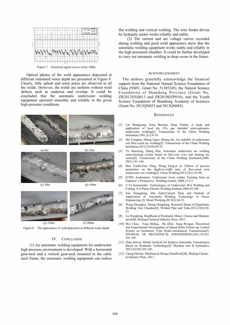
Figure 7. Electrical signal curves of the 100m
Optical photos of the weld appearance deposited at different simulated water depth are presented in Figure 8. Clearly, little splash and some pores are observed in all the welds. However, the welds are uniform without weld defects such as undercut and overlap. It could be concluded that the automatic underwater welding equipment operated smoothly and reliably in the given high-pressure conditions.
(a) 0m (b) 10m
(c) 30m (d) 100m
(e) 150m (f) 200m
Figure 8. The appearance of weld deposited at different water depth
IV. CONCLUSION
(1) An automatic welding equipment for underwater high pressure environment is developed. With a horizontal gear-rack and a vertical gear-rack mounted in the cubic steel frame, the automatic welding equipment can realize
flat welding and vertical welding. The wire feeder driven by hydraulic motor works reliably and stably.
(2) The current and arc voltage curves recorded during welding and good weld appearance show that the automatic welding equipment works stably and reliably in the high pressured chamber. It could be further developed to carry out automatic welding in deep ocean in the future.
ACKNOWLEDGMENT
The authors gratefully acknowledge the financial support from the National Natural Science Foundation of China (NSFC, Grant No. 51305245), the Natural Science Foundat ion of Shandong Province (Grant No. ZR2012EEQ013 and ZR2014EEP016), and the Youth Science Foundation of Shandong Academy of Sciences (Grant No. 2013QN033 and 2013QN043).
REFERENCES
[1] Lin Shangyang, Song Baotian, Song Tianhu. A study and
application of local dry CO2 gas shielded semi-automatic underwater welding[J]. Transactions of the China Welding Institution,1981,2(1):9-19.
[2] Shi Yonghua, Zheng Zepei, Huang Jin. Arc stability of underwater wet flux-cored arc welding[J]. Transactions of the China Welding Institution,2012,33(10):49-53.
[3] Ye Jianxiong, Zhang Hua. Automatic underwater arc welding seam-tracking system based on flux-core wire and rotating arc sensor[J]. Transactions of the China Welding Institution,2008, 29(3):141-144.
[4] Han Yanfei,Guo Ning, Wang Fang,et al. Effects of process parameters on the depth-to-width ratio of flux-cored wire underwater wet welding[J]. China Welding,2013,22(1):35-40.
[5] [UWE Aschemeier. Underwater (wet) welder Training from an Engineer’s Prospective. Welding Journal. 2008,11:2-5.
[6] V.Ya Kononenko. Technologies of Underwater Wet Welding and Cutting. E.O.Paton Electric Welding Institute.2006:92-108.
[7] Jiao Xiangdong, Zhu Jialei.Current State and Outlook of Application of Automatic Welding Technology in Ocean Engineering [J]. Metal Working,2013(2):24-32.
[8] Wang Zhonghui, Zhang Dongdong. Research Status of Hyperbaric Welding Test Chamber[J]. Welded Pipe and Tube,2012,35(5):50-53.
[9] Lu Wanglong. Handbook of Hydraulic Motor: Choice and Maintenance[M]. Beijing:Chemical Industry Press, 2011.
[10] Wei Chao, Yuan Shihua, Hu Jibin, Song Weiqun. Theoretical and Experimental Investigation of Speed Ratio Follow-up Control System on Geometric Type Hydro-mechanical Transmission[J]. JOURNAL OF MECHANICAL ENGINEERING,2011,47(16): 101-105.
[11] Zhao Jiawen. Model Analysis for Stepless Automatic Transmission Based on Hydraulic Technology[J]. Machine tool & hydraulics, 2013,41(20):103-105.
[12] Cheng Daxian. Mechanical Design Handbook[M]. Beijing:Chemical Industry Press, 2011.
889