Embed Size (px)
Citation preview

Chapter 0 - 1 © ICCAS 2002
Design and validation of a sensor guided control system for robot welding in shipbuilding
Mikael Fridenfalk, Gunnar Bolmsjö
Division of Robotics, Dept. of Mechanical Engineering
Lund University, Box 118
SE-221 00 Lund, Sweden
Abstract New areas in welding large structures in shipbuilding include joining large sections such as double-hull constructions. Joining these sections create great problems for a manual welder since welding takes place in a closed area with associated work environmental problems. The accessibility to the working area is limited to a man-hole and the use of robots for welding such structures requires new robot design that are adapted for the task as well as the additional requirements of one-off production.
This paper will describe research work and results within the ROWER-2 project. The aim of the project was to design a robot system for joining ship sections in the final stage when ship sections are to be assembled together in dry dock. Due to a high degree of manual work involved in the assembly procedure of the ship, the project addressed both productivity and quality issues. An important part within the project was to develop control algorithms for seam tracking during welding based on through-arc sensing. The aim was to be able to cope with tolerances in the joints after manual setup and tack welding of the structure.
A special software system, FUSE, was developed for this purpose that seamlessly integrates commercial available software tools such as Matlab and Envision (robot simulator). Simulation in FUSE showed that the major part of the development of sensor guided robot control algorithms should be performed by simulation, since it cuts time, expenses and efforts, especially when software simulation is included in the methodology.
Introduction
Robot welding Since manual labor is a highly limited resource, especially when it comes to skilled craftsmen, robot automation is essential for future industrial expansion. One

Chapter 0 - 2 © ICCAS 2002
application area is presently robot welding, by which the welding quality and the environmental conditions for welders are improved and the productivity is increased. This applies especially to robot welding in shipbuilding [23, 24, 25] where large structures are welded, including the joining of large double-hull sections.
Seam tracking Seam tracking [5, 7, 8, 13, 19] is essential for automation in shipbuilding for manufacturing of large passenger and cargo ships, such as supercruisers and oil-tankers, where high tolerances in the sheet material are allowed to minimize manufacturing costs. A great number of Sensor Guided Robot Control (SGRC) systems for seam tracking at arc welding have been developed. The patents within this application area during the last 40 years indicates that there is a clear tendency that old methods using mechanical, inductive, electrical and infrared sensors are becoming less important along with the use of electron beams and camera systems. Today laser scanners and arc sensors mainly replace these systems.
Systems based on laser scanners and arc sensors differ in accuracy, geometry and price. Laser scanners provide for a more accurate signal than arc sensors, which contain much noise due to the interference of the welding process. On the other hand, laser scanners have to be mounted on the torch, decreasing the workspace of the robot. Laser scanners are also significantly more expensive than arc sensors, which perhaps is one of the reasons why the majority of the patents that have been issued during the last 10 years for seam tracking at arc welding [3, 16, 17, 26, 27] are based on through-arc sensing, while systems based on laser scanners are hardly even represented.
Process control Besides seam geometry at seam tracking, considerations have to be made of process related welding parameters [1, 29]. The welding process contains many parameters, such as the arc voltage, wire speed and wire material. The aim is to determine feasible parameters for a welding procedure before seam tracking. This may be performed experimentally or by the use of knowledge based systems [4, 28]. If it is however not possible or desirable to keep these settings constant throughout the seam [14, 15, 18, 27], for instance due to the characteristics of the power-source, adaptive control may be introduced into the seam tracking procedure for maintaining the desired welding quality.
Through-arc sensing The usual methods used for automated arc welding are gas metal arc welding (GMAW), flux-cored arc welding (FCAW) and submerged arc welding (SAW). In GMAW, metal parts are joined together by heating them with an arc established between a continuous, consumable filler metal electrode and the workpiece. The filler metal is either transferred to the workpiece in discrete drops under the influence of electromagnetic forces and gravity or in the form of molten electrode produced by repetitive short-circuiting.
Chapter 0 - 3 © ICCAS 2002
noa
TCP
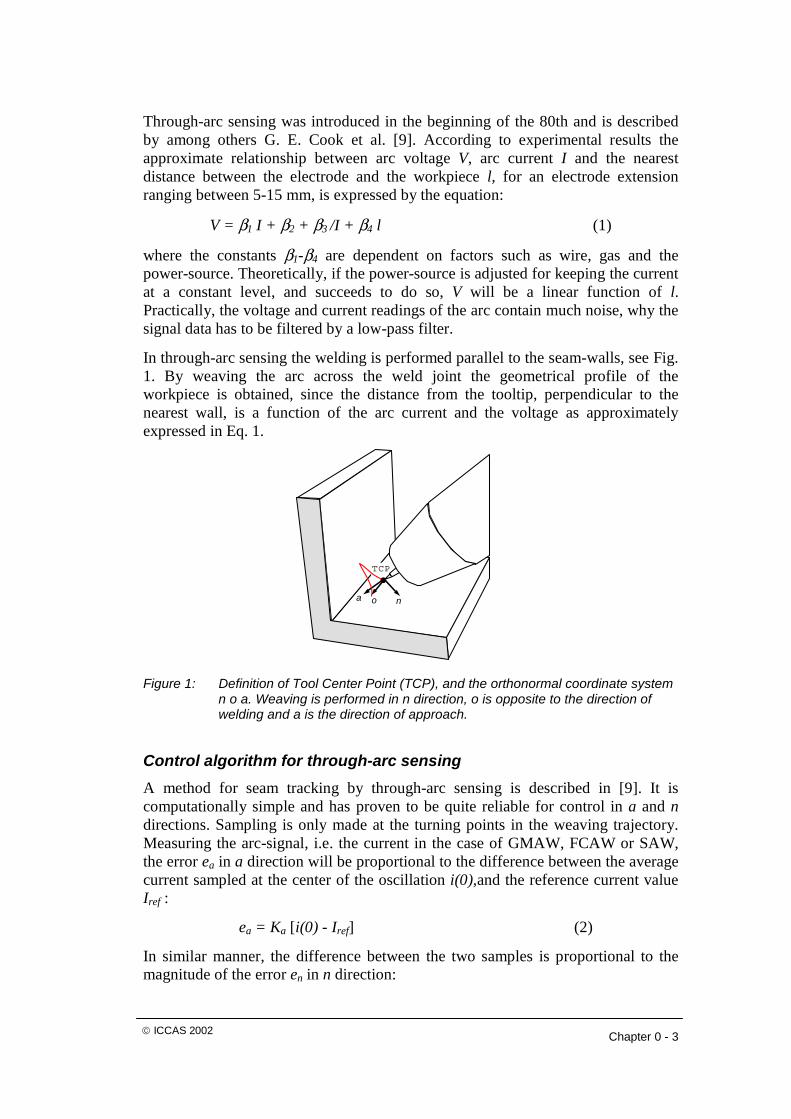
Through-arc sensing was introduced in the beginning of the 80th and is described by among others G. E. Cook et al. [9]. According to experimental results the approximate relationship between arc voltage V, arc current I and the nearest distance between the electrode and the workpiece l, for an electrode extension ranging between 5-15 mm, is expressed by the equation:
V = β1 I + β2 + β3 /I + β4 l (1)
where the constants β1-β4 are dependent on factors such as wire, gas and the power-source. Theoretically, if the power-source is adjusted for keeping the current at a constant level, and succeeds to do so, V will be a linear function of l. Practically, the voltage and current readings of the arc contain much noise, why the signal data has to be filtered by a low-pass filter.
In through-arc sensing the welding is performed parallel to the seam-walls, see Fig. 1. By weaving the arc across the weld joint the geometrical profile of the workpiece is obtained, since the distance from the tooltip, perpendicular to the nearest wall, is a function of the arc current and the voltage as approximately expressed in Eq. 1.
Figure 1: Definition of Tool Center Point (TCP), and the orthonormal coordinate system n o a. Weaving is performed in n direction, o is opposite to the direction of welding and a is the direction of approach.
Control algorithm for through-arc sensing A method for seam tracking by through-arc sensing is described in [9]. It is computationally simple and has proven to be quite reliable for control in a and n directions. Sampling is only made at the turning points in the weaving trajectory. Measuring the arc-signal, i.e. the current in the case of GMAW, FCAW or SAW, the error ea in a direction will be proportional to the difference between the average current sampled at the center of the oscillation i(0),and the reference current value Iref :
ea = Ka [i(0) - Iref] (2)
In similar manner, the difference between the two samples is proportional to the magnitude of the error en in n direction:
Chapter 0 - 4 © ICCAS 2002
en = Ka [i+A - i-A] (3)
where i+A and i-A are the average measured currents at a pair of adjacent extreme points and A is the weaving amplitude. The parameters Ka and Kn are dependent on the weld joint geometry and other process parameters such as shielding gas and wire feed rate. Since these parameters will be known in advance, Ka and Kn may be defined for any welding application.
Simulation using virtual sensors Virtual sensors are presently used in many application areas, such as robotics, aerospace and marine technologies [6, 10, 20, 22]. Development of new robot systems, such as for seam tracking may be accelerated by application of simulation [12]. In general, the design methodology of virtual sensors may vary due to their specific characteristics. If the characteristics are not known for the design of analytical sensor models, artificial neural networks may be used [2, 21].
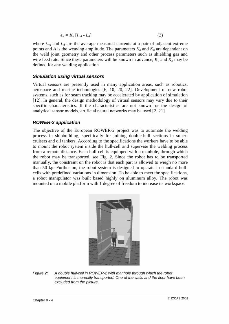
ROWER-2 application The objective of the European ROWER-2 project was to automate the welding process in shipbuilding, specifically for joining double-hull sections in super-cruisers and oil tankers. According to the specifications the workers have to be able to mount the robot system inside the hull-cell and supervise the welding process from a remote distance. Each hull-cell is equipped with a manhole, through which the robot may be transported, see Fig. 2. Since the robot has to be transported manually, the constraint on the robot is that each part is allowed to weigh no more than 50 kg. Further on, the robot system is designed to operate in standard hull-cells with predefined variations in dimension. To be able to meet the specifications, a robot manipulator was built based highly on aluminum alloy. The robot was mounted on a mobile platform with 1 degree of freedom to increase its workspace.
Figure 2: A double hull-cell in ROWER-2 with manhole through which the robot equipment is manually transported. One of the walls and the floor have been excluded from the picture.

Chapter 0 - 5 © ICCAS 2002
The method chosen for automatic welding in the ROWER-2 project was GMAW using through-arc sensing at seam tracking [9]. A simple seam tracking algorithm was developed at an early stage of the project [13]. By the application of the Flexible Unified Simulation Environment (FUSE) [11], this algorithm was optimized and evolved into many new algorithms. FUSE is an integrated software system based on Envision (robot simulator, Delmia Inc.) and Matlab (MathWorks Inc.). The algorithms were initially designed to contain the basic functionality of the Yaskawa COM-ARC III sensor [30] but were further developed to meet the ROWER-2 specifications along with others added by the authors.
Since one of the simple algorithms showed by simulation to meet the ROWER-2 specifications, it was chosen for implementation in the project. The implementation was performed in C++, running on a QNX-based embedded system. The algorithm was further developed to be able to handle long welds by using linear interpolation. A method was additionally developed to compensate for the power-source controller that interfered with the seam tracking process by disabling control in negative a direction of the TCP. Automatic delay detection for synchronization between the control system and the data received from the arc sensor was additionally designed and implemented to secure control in n direction of TCP.
Materials and methods
Systems development methodology The methodology is based on the assumption that software development in robotics is the part that requires most time, money and effort at development of robot systems. To optimize the procedure of robot design from virtual prototyping and systems development to the final integration of the robot in a production line, a new software system was designed that can be used during the whole process. FUSE fills the gap that traditionally exists between CAD/CAM/CAE, robot simulation systems and software simulation environments.
Figure 3 presents the methodology that was developed and used for the design and validation of a seam tracking algorithm in the ROWER-2 project. In this figure design of model denotes the design of a model that is focused on the functionality of the algorithm. Simulation and verification of the model denotes the process of estimating the potential and finding the limitations of the algorithm. Software structure simulation is not bound to the model itself but to the implementation of the model at a later stage.
It is an awkward task to debug complex algorithms after they have been implemented in a robot system. At an early development stage, however, a detailed simulation of the execution flow, supported by automatic testing programs will most likely isolate the problems. The test programs may be used to systematically find the limits of the algorithm and make sure that it behaves as expected. Any significant change in the algorithm structure in the verification phase implies similar changes in the simulation model of the software to mirror the program flow in the robot system. If the algorithm has been developed with care using software simulation to begin with, such modification will require minimal effort.

Chapter 0 - 6 © ICCAS 2002
Yes
No
Design of model based on specifications
Simulation and verification of model
Simulation of software structure
Evaluation of simulation model
Are the specifications met?
Implementation ofsoftware code in C++
Physical experiments and validation
QN
XE
XP
FU
SE
FU
SE
FU
SE
FU
SE
3−6 mm
70−1100 20−30 0
Fillet joint
V−groove joint
Plate thickness: 10−15 mm
y
zy
z
By physical validation, deficiencies may be found in the simulation model. If the specifications are not met, the model is modified and new model and program structure simulations are performed. When the specifications are met by physical validation, the process is terminated by a final evaluation of the simulation model using the optimized parameters found by physical validation.
Figure 3: The methodology developed for the design and physical validation of the seam tracking algorithm in the ROWER-2 project.
Figure 4: Fillet and V-groove joints were used in simulation and physical validation. The lengths of the sample plates in the experiments were 600 mm (orthogonal to the plane of the figure).
Chapter 0 - 7 © ICCAS 2002
Joint profiles The simulation was performed on fillet and V-groove joints, according to the specifications in the ROWER-2 project. Due to these, the algorithm had to be able to make compensations for deviations of +/-300 mm in y and z directions (see Fig. 4) during a 15 m long weld. This was redefined as a maximum deviation of +/-20 mm per meter weld, or +/-2% expressed in percentage. Profiles of fillet and V-groove joints are presented in Fig. 4. Since the start point of the seam is always found by image processing before seam tracking is performed, no special consideration is taken at start.
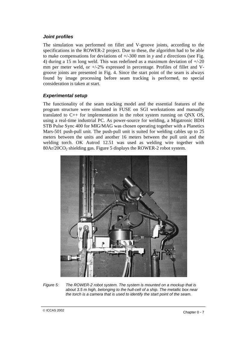
Experimental setup The functionality of the seam tracking model and the essential features of the program structure were simulated in FUSE on SGI workstations and manually translated to C++ for implementation in the robot system running on QNX OS, using a real-time industrial PC. As power-source for welding, a Migatronic BDH STB Pulse Sync 400 for MIG/MAG was chosen operating together with a Planetics Mars-501 push-pull unit. The push-pull unit is suited for welding cables up to 25 meters between the units and another 16 meters between the pull unit and the welding torch. OK Autrod 12.51 was used as welding wire together with 80Ar/20CO2 shielding gas. Figure 5 displays the ROWER-2 robot system.
Figure 5: The ROWER-2 robot system. The system is mounted on a mockup that is about 3.5 m high, belonging to the hull-cell of a ship. The metallic box near the torch is a camera that is used to identify the start point of the seam.
Chapter 0 - 8 © ICCAS 2002
Experimental results
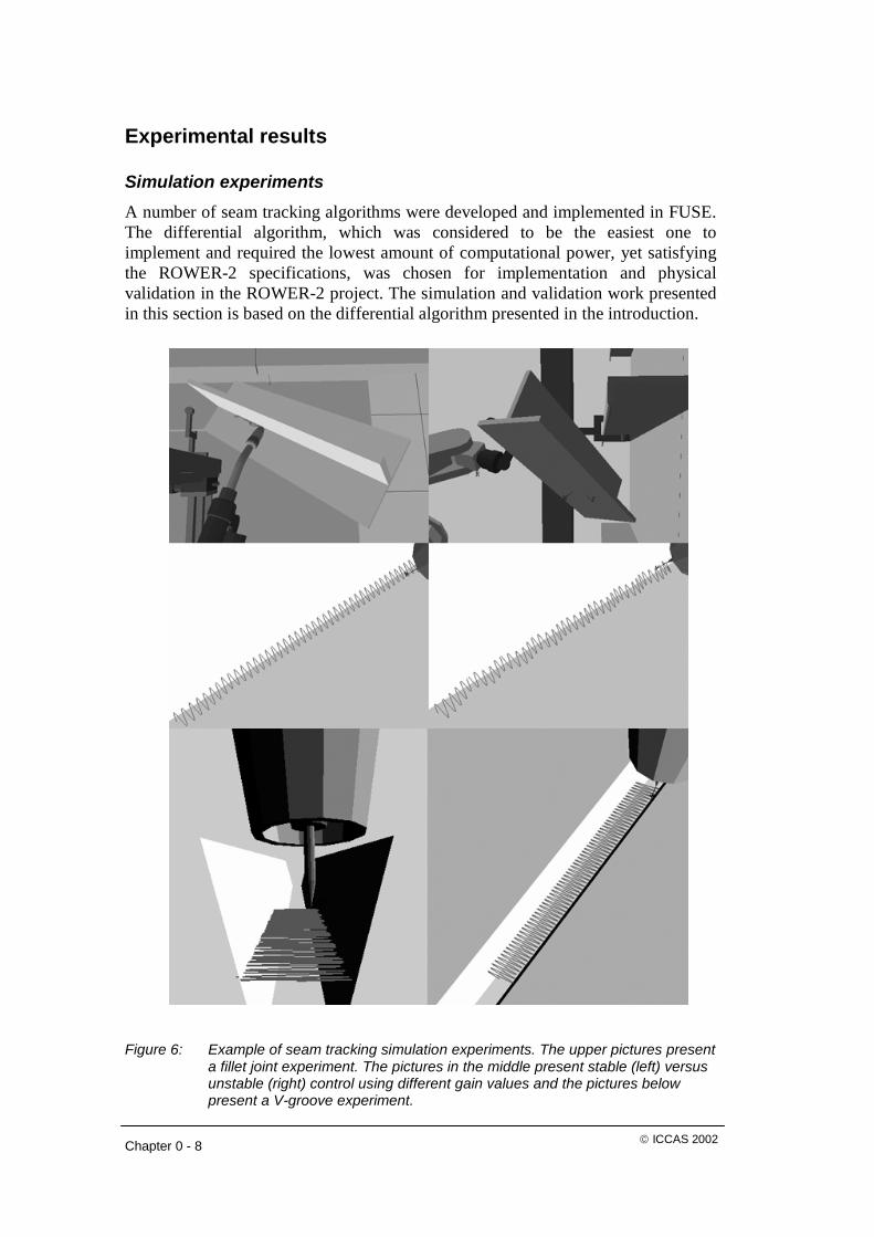
Simulation experiments A number of seam tracking algorithms were developed and implemented in FUSE. The differential algorithm, which was considered to be the easiest one to implement and required the lowest amount of computational power, yet satisfying the ROWER-2 specifications, was chosen for implementation and physical validation in the ROWER-2 project. The simulation and validation work presented in this section is based on the differential algorithm presented in the introduction.
Figure 6: Example of seam tracking simulation experiments. The upper pictures present
a fillet joint experiment. The pictures in the middle present stable (left) versus unstable (right) control using different gain values and the pictures below present a V-groove experiment.
Chapter 0 - 9 © ICCAS 2002
Initial simulations showed that the differential algorithm was theoretically able to meet the specifications. By physical experiments, the model was modified due to changes of parameters such as welding speed, weaving amplitude and frequency. These data, along with other data such as nominal voltage, were optimized by a series of tests performed by an experienced welding specialist tuning the welding system. For evaluation of the simulation model compared to real experiments, a final series of simulations were performed using the power-source parameters that had shown to give high quality welds. According to the evaluation, the theoretical limits for the algorithm is a deviation in the interval between –10% and 30% with Ka = 0.01 and Kn = 0.005. This is better than +/-2% (specifications). The conclusion is that the ideal case, when the current has very low amount of noise and Eq. 1 is valid, the maximum allowed deviation is +/-20% (moving the nominal welding trajectory offset to the middle). The asymmetrical performance (–10% to 30%) is most likely related to the present control system.
Figure 6 presents a few simulations performed for evaluation purpose after the verification of the algorithm by a series of real experiments. In these experiments Kn was 50% of Ka, which is an empirically derived optimal value verified by robot welding experiments.
The criterion for a good weld is that the final result should at ocular examination be similar to a straight weld without seam tracking. To be able to produce such result, the smallest gains that still made it possible to meet the specifications had to be found, minimizing the instability that occurred during SGRC. At too low gains, the algorithm does not compensate enough. On the other hand, if the gain is too large, instability will occur resulting in low welding quality. So the trick is to find the largest gains for Ka and Kn both for positive and negative deviations and both for fillet and V-groove welds at which the seam tracking remains stable and converges smoothly to the seam. At these gains the maximum possible deviations are experimentally found by increasing the deviation step by step until the algorithm has reached the limits of its performance.
Validation by robot welding
Overview
Initial simulations showed that the algorithm used less than 1% of the computational power it was assigned, which equals 1/2000 of the total computational power of the real-time embedded system, so the efforts to produce efficient code was successful. The simulation and validation loop described in Fig. 3 was repeated twice and concluded with evaluation simulations. The first physical experiments consisted of a number of fillet, V-groove and flat surface welds performed by the robot, with and without seam tracking. The primary task was to find the set of parameters for the power-source that resulted in good welding quality.
The second robot welding experiments were performed on author requests and consisted of about 25 fillet and 25 V-groove joints. Also as a final evaluation of the implemented algorithm 10 fillet and 10 V-groove welds were carried out. In addition, an uncounted number of fillet and V-groove welds were performed to find

Chapter 0 - 10 © ICCAS 2002
good parameter settings for the power-source. The overhead experiments showed to be many compared to the pure seam tracking experiments. About 120 fillet and 75 V-groove joint workpieces were estimated to have been used during the two experimental occasions. These overhead experiments showed to be very important for the development of the algorithm. Without precise parameter settings of the power-source seam tracking would have worked, but without producing high quality welds.
Anomalies caused by power-source
In theory, seam tracking requires that the relation between arc voltage and current is known, such as by Eq. 1. Usually the voltage is held constant, while current changes due to the distance between wire and workpiece. In synergic welding however, both current and voltage are modified by the control system of the power-source, causing disruption in the control system of the algorithm. Early experiments with the Migatronic power-source, using the pure synergic mode showed that this mode disabled algorithm control in the negative approach direction of the TCP.
Initial seam tracking experiments using manual mode showed that the current constantly decreased throughout the weld, making compensation in negative a direction impossible. A thorough examination of the current sensor showed that the current measurements were both stable and sufficiently accurate for the application and that the decrease of current throughout the weld was not due to measurement errors. The conclusion was therefore that the Migatronic power-source controller was most likely controlling the current also at manual mode. The reason is assumed to be that modern power-sources also include some adaptive control in manual mode to assist humans in performing high quality welds.
Compensation for power-source control
Addition of a constantly increasing offset to the nominal trajectory in negative a direction, solved the problem caused by the adaptive behavior of the power-source. To be able to handle negative deviations, Ka had to be doubled. The method was tested for fillet joints and showed to be a reliable and permanent solution to this problem. Since the same principal is valid for fillet as V-groove welds, no experimental series were considered necessary to prove the validity of the power-source compensation for V-groove welds.
Power-source parameter settings
The following data was primarily acquired and logged during the second experimental series consisting of 80 fillet and V-groove experiments: (1) objective, (2) label, (3) Ka, Kn, (4) deviations in y and z directions, (5) welding speed, (6) weaving frequency and amplitude, (7) weaving shape, (8) nominal voltage and current, (9) wire speed, (10) a detailed description of the results. The optimal parameters that were experimentally found giving high welding quality, are presented in Table 1.

Chapter 0 - 11 © ICCAS 2002
Parameter Fillet weld V-groove weld
Nominal Voltage (V)
Ka
Kn
Weaving frequency (Hz)
Weaving shape
Welding speed (mm/s)
Wire speed (m/min)
Weaving amplitude (mm)
28
0.015
50% of Ka
3
Sinesquare
8
9
3
28.5
0.012
50% of Ka
2
Sawtooth
3.5
7
4
Table 1: Recommended parameters using the Migatronic power-source, derived by experiments. Sinesquare denotes a sine wave that is truncated at +/-A/2.
Review of fillet welds
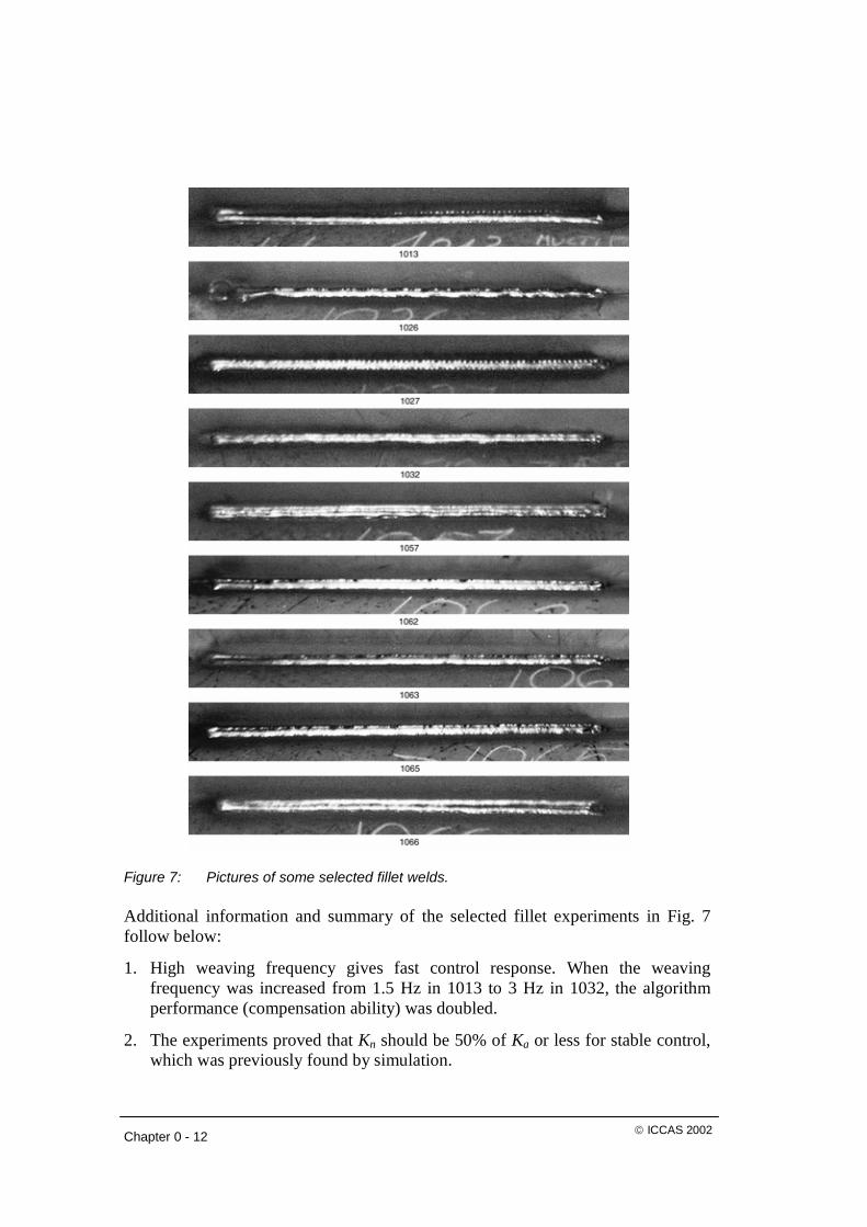
Results from the initial experiments were used for the modification of the algorithm followed by a new simulation set. Some selected fillet and V-groove experiments are presented by photos in Figs. 7 and 8. These experiments are further commented and reviewed below:
1013. Deviation in z direction by 8%, followed by multipass welding. Since Ka and f were too small, seam tracking failed by a deviation of 2.3%. Ka = 0.05, f = 1.5 Hz.
1026. Deviation in y direction by 4%. Kn was too high and caused oscillations in n direction. Ka = 0.05, f = 3 Hz.
1027. Reference welding without seam tracking, nearly optimal with f = 3 Hz. The distinct edges of the weaving indicates too high nominal voltage, cutting too deep into the workpiece.
1032. Deviations in y and z directions by 8%. High welding quality, but this is the limit for positive deviations. Ka = 0.025, f = 3 Hz.
1057. Deviations in both y and z directions by 2% (specifications). High welding quality in both root and multipass layers. Ka = 0.0125, f = 3 Hz.
1062. Final test. Deviation in y direction by 2% (specifications), using power-source compensation. High welding quality. Some instability occurred at the beginning of the seam and the stick-out was 3 mm too large at the end of the seam. Ka = 0.015, f = 3 Hz.
1063, 1065-1066. Final tests. Deviations of –2% for 1063 and 2% for 1065-1066 in y and z directions (specifications), using power-source compensation. High welding quality. Ka = 0.015, f = 3 Hz. Multipass welding in 1066. The stick-out was 3 mm too large throughout the seam for 1063 and 3 mm too large at the end of 1065-1066. Due to interference with the root layer at multipass welding, the last of the three layers deviated by 2 mm at the end of the seam.
Chapter 0 - 12 © ICCAS 2002
Figure 7: Pictures of some selected fillet welds.
Additional information and summary of the selected fillet experiments in Fig. 7 follow below:
1. High weaving frequency gives fast control response. When the weaving frequency was increased from 1.5 Hz in 1013 to 3 Hz in 1032, the algorithm performance (compensation ability) was doubled.
2. The experiments proved that Kn should be 50% of Ka or less for stable control, which was previously found by simulation.

Chapter 0 - 13 © ICCAS 2002
3. In the presented fillet experiments, Kn was 50% of Ka in all cases except in 1013 where it was 75%. Due to problems in the newly developed robot system (regarding tuning of the motor control unit) the highest weaving frequency that could be used was 2-3 Hz. At 3 Hz, the weaving amplitude was not able to exceed 3 mm despite the setting of 5 mm.
4. The fluctuation that occurred in the beginning of the seam in 1062 was due to the applied automatic calibration method. It was however found that the same reference current value could be used in the algorithm for all fillet welds, eliminating the fluctuations at start.
5. The stick-out (of the wire) was in some experiments 3 mm larger than desired, according to the welding specialist. This did not effect welding quality in the root layer, but effected the multi-pass layers, since subsequent layers interfered with the root layer. This interference was not larger than about 2 mm, but for high welding quality at multipass welding the algorithm should be fine-tuned to be able to reduce the stick-out some millimeters. One way to achieve this is to slightly increase the reference current value. The power-source compensation should also be amplified to avoid collision of the torch with the workpiece.
6. The most important result from this experimental series was that power-source compensation showed to work properly.
Figure 8: Pictures of some selected V-groove welds.
Review of V-groove welds
Below follows comments on some of the V-groove welding experiments, presented in Fig. 8:
2031. Deviation in y direction by –2%. High welding quality. Ka = 0.015, f = 2 Hz.
2033. Deviations in y and z directions by 2%. Seam tracking failed due to small compensation caused by the average current estimator. A 10 mm too large stick-out caused bubbles in the weld and a poor welding quality. Ka = 0.020, f = 2 Hz.

Chapter 0 - 14 © ICCAS 2002
2041. Deviations in y and z directions by 2%. High welding quality. Anti-transient current limiters were added to the algorithm and a 230 A threshold was added to the reference current estimator. Ka = 0.012, f = 2 Hz, U = 29 V.
2043. Final test. Deviations in y and z directions by 2%. High welding quality. Basically the same experiment as above, except for U = 28.5 V, for enhanced welding quality. Ka = 0.012, f = 2 Hz.
2047. Final test. Deviation in y direction by 2% with two multipass layers on top of the root layer. High welding quality. Ka = 0.015, f = 2 Hz.
Conclusions The ROWER-2 specifications were fulfilled by the development and physical validation of a seam tracking algorithm distinguished by: (1) stable control in a and n directions for fillet and V-groove joints (negative a direction for V-grooves based on fillet weld experiments), (2) ability to perform multipass welding using interpolation, (3) maintaining high welding quality throughout the seam by good power-source parameter settings and the use of power-source compensation, (4) design and use of an auto-phase analyzer, calculating the total delay in the robot system for accurate control in n direction (A new version of the FFT algorithm was designed and implemented. This special version works faster and is simpler to implement for this specific task than standard FFT), (5) automatic reference current calibration.
Acknowledgements The ROWER-2 project was funded by European Commission under the BRITE/EURAM program.
References 1. S. Adolfsson. Simulation and execution of autonomous robot systems. PhD
thesis, Department of Production and Materials Engineering, Lund University, 1998.
2. M. Arroyo Leon, A. Ruiz Castro, and R. Leal Ascencio. An artificial neural network on a field programmable gate array as a virtual sensor. In Design of Mixed-Mode Integrated Circuits and Applications, 1999. Third International Workshop on, pages 114-117, July 1999.
3. P. Berbakov, D. MacLauchlan, and D. Stevens. Edge detection and seam tracking with Emats. Patent No. US6155117, Dec. 2000.
4. G. Bolmsjö. Knowledge based systems in robotized arc welding. In International Journal for the Joining of Materials, vol. 9 (4), pages 139-151, 1997.
Chapter 0 - 15 © ICCAS 2002
5. G. Bolmsjö. Sensor systems in arc welding. Technical report, Robotics Group, Department of Production and Materials Engineering, Lund University, Sweden, 1997.
6. G. Bolmsjö. Programming robot welding systems using advanced simulation tools. In Proceedings of the International Conference on the Joining of Materials, pages 284-291, Helsingør, Denmark, May 16-19 1999.
7. K. Brink, M. Olsson, and G. Bolmsjö. Increased autonomy in industrial robotic systems: A framework. In Journal of Intelligent and Robotic Systems, vol. 19, pages 357-373, 1997.
8. P. Cederberg, M. Olsson, and G. Bolmsjö. A generic sensor interface in robot simulation and control. In Proceedings of Scandinavian Symposium on Robotics 99, pages 221-230, Oulu, Finland, Oct. 14-15 1999.
9. G. E. Cook, K. Andersen, K. R. Fernandez, M. E. Shepard, and A. M. Wells, Jr. Electric arc sensing for robot positioning control. Robot Welding, pages 181-216. Editor: J. D. Lane. IFS Publications Ltd, UK, Springer-Verlag, 1987.
10. W. Doggett and S. Vazquez. An architecture for real-time interpretation and visualization of structural sensor data in a laboratory environment. In Digital Avionics Systems Conferences, 2000. Proceedings. DASC. The 19th, vol. 2, pages 6D2/1-6D2/8, Oct. 2000.
11. M. Fridenfalk and G. Bolmsjö. The Unified Simulation Environment - Envision telerobotics and Matlab merged into one application. In the Proceedings of the Nordic Matlab Conference, pages 177-181, Oslo, Norway, Oct. 2001.
12. M. Fridenfalk, U. Lorentzon, and G. Bolmsjö. Virtual prototyping and experience of modular robotics design based on user involvement. In the Proceedings of the 5th European Conference for the Advancement of Assistive Technology, Düsseldorf, Germany, Nov. 1999.
13. M. Fridenfalk, M. Olsson, and G. Bolmsjö. Simulation based design of a robotic welding system. In Proceedings of the Scandinavian Symposium on Robotics 99, pages 271-280, Oulu, Finland, Oct. 14-15 1999.
14. G. Ågren and P. Hedenborg. Integration of sensors for robot and welding power supply control. In Proceedings of Fifth International Welding Computerization Conference, pages 198-204, Golden, USA (AWS), Aug. 1994.
15. P. Hedenborg and G. Bolmsjö. Task control in robotics arc welding by use of sensors. In Proceedings of the Tampere International Conference on Machine Automation - Mechatronics Spells Profitability, IFAC/IEEE, pages 437-445, Tempre, Finland, Feb. 15-18 1994.
16. K. Hedengren and K. Haefner. Seam-tracking apparatus for a welding system employing an array of eddy current elements. Patent No. US5463201, Oct. 1995.

Chapter 0 - 16 © ICCAS 2002
17. J. Huissoon and D. Strauss. System and method for tracking a feature on an object using a redundant axis. Patent No. US5465037, Nov. 1995.
18. L.-O. Larsson and G. Bolmsjö. A model of optical observable parameters to control robotic GMA welding in sheet steel. In Proceedings of the Fifth International Conference on Computer Technology in Welding, pages 2-10, paper 42, Paris, France, June 15-16 1994.
19. M. Olsson. Simulation and execution of autonomous robot systems. PhD thesis, Division of Robotics, Department of Mechanical Engineering, Lund University, 2002.
20. M. Oosterom and R. Babuska. Virtual sensor for fault detection and isolation in flight control systems - fuzzy modeling approach. In Decision and Control, 2000. Proc. of the 39th IEEE Conf. on, vol. 3, pages 2645-2650, Dec. 2000.
21. H. Pasika, S. Haykin, E. Clothiaux, and R. Stewart. Neural networks for sensor fusion in remote sensing. In Neural Networks, 1999. IJCNN '99. International Joint Conference on, vol. 4, pages 2772-2776, July 1999.
22. P. Ridao, J. Battle, J. Amat, and M. Carreras. A distributed environment for virtual and/or real experiments for underwater robots. In Robotics and Automation, 2001. Proceedings 2001 ICRA. IEEE International Conference on, vol. 4, pages 3250-3255, May 2001.
23. B. Rooks. Robot welding in shipbuilding. The Industrial Robot, 24(6):413-417, 1997.
24. S. Sagatun and S. Hendseth. Efficient off-line programming of robot production systems. In Proceedings of the 27th International Symposium on Industrial Robots. Robotics Towards 2000, pages 787-792, CEU-Centro Esposizioni UCIMU, Cinisello Balsamo, Italy, 1996.
25. P. Sorenti. Efficient robotic welding for shipyards - virtual reality simulation holds the key. The Industrial Robot, 24(4):278-281, 1997.
26. Y. Suzuki. Method and apparatus for determining seam tracking control of arc welding. Patent No. EP1077101, Feb. 2001.
27. J. Villafuerte. Arc welding torch. Patent No. US6130407, Oct. 2000.
28. M. Xie and G. Bolmsjö. Using expert systems in arc monitoring and causal diagnosis in robotic arc welding. In International Journal for the Joining of Materials, vol. 4 (4), 1992.
29. M. Xie and G. Bolmsjö. Quality assurance and control for robotic GMA welding - part 1: QA model and welding procedure specification. In Joining Sciences, vol. 1 (4), 1993.
30. Yaskawa. Arc Sensor COM-ARC III Instructions.