Embed Size (px)
Citation preview
October 2016 Page 1 of 21
Alberta Roadside Design Guide
High Tension Cable Barrier System – Median and Roadside Installation
October 27, 2016 Rewrite of Design Bulletin #75/2012
April 5, 2012 Amendment to Design Bulletin #75/2012
- Section 5.5 Placement of HTCB on the Roadside: distance of slope behind the barrier. - Drawing RDG–B2.4, Rev. 1
The subjects covered by this bulletin are as follows: 1.0 SUMMARY ................................................................................................................ 2 2.0 LONGITUDINAL TRAFFIC BARRIER SYSTEM SELECTION ................................. 3
2.1 Alberta Transportation Product Development and Acceptance Testing ............................... 3 3.0 OVERVIEW OF HIGH TENSION CABLE BARRIER ................................................ 3
3.1 Testing and Approval of HTCB under NCHRP Report 350 and/or MASH 2009 ................ 4 4.0 GENERAL DESIGN PROCESS................................................................................ 6
4.1 Obtain Information Regarding Available Accepted HTCB Systems .................................... 6 4.2 Compile the Physical Characteristics of the Project Site ...................................................... 7 4.3 Determine Space Availability for HTCB Deflection, Required Test Level (3 or 4) and Cable Configuration (3 or 4) ....................................................................................................... 7 4.4 Ensure Competitive Bidding ................................................................................................. 8 4.5 Specify the Design Criteria and Considerations ................................................................... 9 4.6 Undertake the Design ............................................................................................................ 9 4.7 Package the Tender ............................................................................................................. 10
5.0 DESIGN GUIDELINES............................................................................................ 10 5.1 Specified Maximum Deflection and Post Spacing ............................................................. 10 5.2 Placement of HTCB in the Median ..................................................................................... 10
5.2.1 Desirable Deflection Space .......................................................................................... 11 5.2.2 HTCB Placement in Depressed Medians ..................................................................... 11
5.3 Placement of HTCB on the Roadside (non-median) .......................................................... 13 5.4 Placement of HTCB on Undivided Highways – Considering Wide Loads, Farm Equipment and Nuisance Hits ..................................................................................................................... 15 5.5 Placement of HTCB in the Vicinity of a Bridgerail Transition .......................................... 16 5.6 Placement on Curved Horizontal Alignments .................................................................... 16 5.7 Placement on Curved Vertical Alignments ......................................................................... 17 5.8 End Treatment or Anchors .................................................................................................. 17 5.9 Anchor Spacing - Run Length............................................................................................. 18 5.10 Overlapping Barrier Systems ............................................................................................ 18 5.11 Conditions Where Cable Barrier May Replace Existing, Less Flexible Barriers ............. 19 5.12 Geotechnical Investigation / Soil Conditions.................................................................... 19
DESIGN BULLETIN #75/2012 (Rewritten October 2016)
October 2016 Page 2 of 21
6.0 EFFECTIVE DATE .................................................................................................. 20 7.0 CONTACT ............................................................................................................... 20 8.0 REFERENCES ........................................................................................................ 20 1.0 SUMMARY This Bulletin is issued to inform practitioners of the Alberta Transportation (AT) guidelines regarding the use of High Tension Cable Barrier (HTCB) installed in the median and on the roadside (right hand side in the direction of travel) of the roadway. Cable barrier has been proven to effectively prevent or reduce the severity of median cross-over crashes and run-off-road crashes. HTCB installed at median and roadside locations has been shown to be the most forgiving barrier system available for reducing the severity of run-off-road crashes in many applications. Alberta Transportation has conducted a before-and-after safety evaluation of the 11 km median HTCB that was installed on the Deerfoot Trail, in Calgary, in May, 2007. As of October 2016, the barrier system has performed very well. No vehicles have crossed the median into oncoming traffic since the installation. There have been no cross-the-median fatalities. Also, there has been a significant reduction in the frequency (per km per year) and rate (per million vehicle-kilometres) of severe median collisions, which are defined as collisions involving major injuries and fatalities. A before-and-after safety evaluation of the 122 km median HTCB installed on Highway 2, between Airdrie and Red Deer in June 2010, has also been conducted. The evaluation indicates a substantial reduction in the frequency and rate of cross-the-median head-on collisions. Depending on the application, HTCB generally has many advantages over other types of barrier systems. Advantages of HTCB include the following:
• Tensioned cables deflect and cushion the force of the hitting vehicle and are, therefore, a more forgiving barrier system when compared to concrete and steel systems (i.e. F-Shape, Single Slope Concrete, W-beam, Strong Post, Thrie Beam, Modified Thrie Beam, Box Beam, etc.);
• Reduced snow drifting; • Low risk for motorists (greater deflection); • Reduced collision severity (i.e. fatalities and injuries); • Reduced damage to vehicles; • Cost to install is generally less than concrete and steel barrier systems; • If impacted, relatively fast and easy to repair; • Often continues to provide protection even after impact and prior to repairs. The
tension keeps the cable near the design height even when the posts are damaged and or have broken off;
• Improved sight distance where conventional barrier would block the line of sight; • Aesthetic appeal.
October 2016 Page 3 of 21
2.0 LONGITUDINAL TRAFFIC BARRIER SYSTEM SELECTION As indicated in the Alberta Transportation “Roadside Design Guide” November 2007 (Ref 1) practitioners should select a median or roadside barrier system based on the following: Longitudinal traffic barrier systems that are more forgiving are preferred because they may reduce injuries and fatalities when crashes occur, provided that suitable operating space is, or can be made, available. In order of most forgiving to the most rigid barrier systems typically used in Alberta, HTCB is the most forgiving. Concrete barrier systems are the least forgiving (most rigid). 2.1 Alberta Transportation Product Development and Acceptance Testing The Alberta Transportation Products List of proven, trial and potential products for HTCB (including vendor information) is available at the link indicated below. There are currently four suppliers of proprietary HTCB on the Products List (Traffic Control Devices) dated September 8, 2016. http://www.transportation.alberta.ca/689.htm 3.0 OVERVIEW OF HIGH TENSION CABLE BARRIER Generic (non-tensioned) cable barrier has been used as median and roadside barrier since the 1930s. HTCB has supplanted the generic cable barrier as a median barrier since the 1980s. HTCB has three or four, 19 mm (3/4 inch), 3x7 galvanized steel cables. Each cable is comprised of 3 strands and each strand is made up of 7 identical steel wires. The cables are held at the desired height by steel posts that are placed in sockets (also referred to as sleeves). The sockets are driven into the ground or placed in concrete or steel foundations depending on the soil condition, manufacturer’s specification, FHWA Eligibility Letters or the recommendation of an Alberta registered Professional Engineer (specialized in foundation engineering or geotechnical engineering). Installation must allow for replacement of posts in original sockets after collision damage. Posts driven directly into the ground are not permitted on Alberta highways. The cables are individually connected to end terminals (anchors) that are placed in steel or concrete foundations. Anchors require the same type of detailed engineering and acceptance based on generic crash testing, as well as an engineering recommendation based on local soil information and other site conditions. Pre-stretched, post-tensioned galvanized cables are specified for Alberta Transportation projects. Cables are pre-stretched and post-tensioned after installation to a value depending upon ambient temperature, e.g. 25 kN (5,600 pounds) at 21° C (70° F). The FHWA has indicated that “pre-stretched cables have advantages including reduced
October 2016 Page 4 of 21
dynamic deflection by reducing the "play" between the individual wire strands in the bundle that forms the cable prior to installation.” (Ref 2) The posts are expected to break away on impact and the tensioned cables deflect and cushion the force of the hitting vehicle. Cables are typically supplied in 1,000 ft. (303 m) lengths and are connected by turnbuckles or acorns. The cables are very strong and will normally deflect, but not break, in typical highway crashes. 3.1 Testing and Approval of HTCB under NCHRP Report 350 and/or MASH 2009 As of September 8, 2016 there are five proprietary HTCB systems in North America that have passed NCHRP 350 and/or MASH 2009. They are listed below in alphabetical order. Not all of the tested systems are on the Alberta Transportation Products List.
• Brifen Canada 15521 Marine Drive White Rock, BC V4B 1C9, Canada http://www.brifen.ca
• Gibraltar 4303 Innovation Loop Marble Falls, TX 78654, USA http://gibraltarus.com
• Nucor Steel Marion, Inc. 912 Cheney Avenue Marion, Ohio 43302, USA http://www.nucorhighway.com (Note: Not on Alberta Transportation’s Products List dated September 8, 2016)
• SAFENCE (Gregory Industries, Inc.) 4100 13th Street, SW Canton, Ohio 44710, USA http://www.gregorycorp.com
• Trinity Highway Safety Products 2525 North Stemmons Freeway Dallas, Texas 75207, USA http://www.highwayguardrail.com
All HTCB systems work on the same “physics” principle, but can vary significantly in post cross-section, cable/post connection, cable heights, design of post and anchor foundations, post spacing, test deflection, etc. Some of the five suppliers supply only four-cable HTCB, while others supply both three-cable and four-cable HTCB. New HTCB systems and any major changes to existing systems are required to be tested by independent laboratories under prescribed conditions. The test results are submitted by
October 2016 Page 5 of 21
the suppliers to the US Federal Highway Administration (FHWA) which then issues Eligibility Letters (previously referred to as “Acceptance Letters”) based on the test results, for the individual systems. The FHWA issues the letters to developers, manufacturers and other petitioners recognizing their certifications that the hardware they represent have been crash tested and meet the appropriate crash testing criteria. FHWA letters identify, among other things, the major properties of the HTCB system such as test post spacing and test deflection. The letters also include or refer to various FHWA and American Association of State Highway and Transportation Officials (AASHTO) guidelines and caveats for the placement and installation of the particular system being accepted. Previously, all longitudinal barriers accepted for highway application were required to meet the test conditions stated in the Transportation Research Board (TRB) National Cooperative Highway Research Program (NCHRP) Report 350, “Recommended Procedures for the Safety Performance Evaluation of Highway Features” which established six test levels (TL) for longitudinal barriers. TL-1, TL-2, and TL-3 tests involve two test vehicles (an 820 kg car impacting a barrier at 20 degrees and a 2,000 kg pickup truck impacting a barrier at 25 degrees) at speeds of 50 km/h for TL-1, 70 km/h for TL-2 and 100 km/h for TL-3. TL-4 adds an 8,000-kg single-unit truck at 15 degrees and 80 km/h to the TL-3 matrix. TL-5 substitutes a 36,000-kg tractor/van trailer for the single-unit truck. TL-6 substitutes a 36,000-kg tractor/tank trailer. No HTCB has been tested at TL-5 and TL-6 to date. The 2009 “Manual for Assessing Safety Hardware” (MASH 2009), published by AASHTO, is an update to and supersedes NCHRP Report 350 for the purpose of evaluating new safety hardware devices. MASH was developed through NCHRP Project 22-14(02). MASH contains revised criteria for impact performance evaluation of highway safety devices. Updates to MASH include an increase in the size of several test vehicles to better match the current vehicle fleet, changes to the number and impact conditions of the test matrices and more objective, quantitative evaluation criteria. An implementation plan for MASH that was adopted jointly by AASHTO and FHWA states that all highway safety hardware accepted prior to the adoption of MASH (using criteria contained in NCHRP Report 350) may remain in place and may continue to be manufactured and installed. In addition, highway safety hardware accepted using NCHRP Report 350 criteria is not required to be retested using MASH criteria. However, new highway safety hardware, not previously evaluated, must utilize MASH for testing and evaluation. For installation on 6H:1V or flatter side slopes, FHWA has accepted both TL-3 and TL-4 systems of the five suppliers. These acceptances were based on tests on level ground. However, in the tests on a 4H:1V slope, the suppliers have tested their 6H:1V, TL-4 systems only with a pickup truck and not with a single-unit truck. Therefore FHWA has accepted the 4H:1V tests only as TL-3 systems. There are no TL-4 systems available for installation on 4H:1V slopes. There is no accepted HTCB for installation on side slopes
October 2016 Page 6 of 21
steeper than 4H:1V. The information above pertains to installations on median or roadside (non-median) locations. 4.0 GENERAL DESIGN PROCESS This section describes the suggested design process for HTCBs. Some specific design guidelines are indicated in the next section. The interactive nature of the various design elements and the physical site characteristics may necessitate an iterative design approach. 4.1 Obtain Information Regarding Available Accepted HTCB Systems All cable barriers shall meet the crash test requirements of NCHRP Report 350 or MASH 2009 (AASHTO, “Manual for Assessing Safety Hardware”, 2009), as accepted by FHWA in Eligibility Letters issued for individual HTCB systems and products. The FHWA Eligibility Letters on cable barrier systems can be found on the FHWA web page for longitudinal barriers: http://safety.fhwa.dot.gov/roadway_dept/policy_guide/road_hardware/barriers/ Due to ongoing development, new products, research, studies and guidelines on cable barrier, designers shall research and review studies and guidelines as well as products currently available, tested and accepted by FHWA at the time of the project. There may be a time lag between the issuing of FHWA Eligibility Letters and posting of the letters on the FHWA website. FHWA also issues periodic guidelines regarding HTCB, such as the July 20, 2007 Memorandum from Jeffrey A. Lindley, Associate Administrator for Safety, on the subject of “INFORMATION: Cable Barrier Considerations”. (Ref 2) Designers should therefore contact FHWA to obtain the latest information regarding HTCB-related Eligibility Letters and guidelines. Designers should review the FHWA Eligibility Letters and the test documentation upon which the letters are based in detail. This includes the summary results (e.g. test deflection), test site conditions (e.g. post spacing, soil data, etc.), product details, provisions, etc. under which the product was tested and accepted. High Tension Cable Barriers are proprietary products and therefore must be installed and maintained in accordance with the manufacturer’s and/or vendor’s specifications. Cable barrier products vary substantially in details, specification and method of installation, etc. Designers should review the FHWA Eligibility Letters in conjunction with the manufacturer and/or vendor’s product details and specifications.
October 2016 Page 7 of 21
When reviewing the FHWA Eligibility Letters and the suppliers’ literature, the following are some of the factors that should be kept in mind:
• More than one FHWA Eligibility Letter issued on different dates may apply to a given HTCB system, because of updated products, newer components or design changes tested and submitted by the suppliers;
• FHWA might have permitted interpolation, e.g. for correlation between test deflection and post spacing, on the basis of tests done at various post spacing. Also, FHWA might have, without a new test, allowed the addition of a fourth cable to a previously tested and accepted three-cable HTCB system;
• As noted above, for installation on 6H:1V or flatter side slopes, FHWA has accepted both TL-3 and TL-4 systems of the five suppliers. These acceptances were based on tests on level ground. However, in the tests on a 4H:1V slope, the suppliers have tested their 6H:1V TL-4 systems only with a pickup truck and not with a single-unit truck. Therefore FHWA has accepted the 4H:1V tests only as TL-3 systems. There are no TL-4 systems currently available for installation on 4H:1V slopes. There is no accepted HTCB for installation on side slopes steeper than 4H:1V. The “slope” described here refers to the slope a vehicle would be travelling on prior to impact with the system and therefore this is the slope on both sides of the system in a median application and only on the road side in a “roadside” application.
4.2 Compile the Physical Characteristics of the Project Site The lateral placement of the HTCB is a crucial design decision, which in turn requires a detailed knowledge of the nature and location of the physical characteristics of the project site. This information, in the form of plans and summary tables, would ideally be based on accurate record plans that show both above-ground and subsurface conditions, supplemented with specific field measurements taken during the survey/preliminary design stage; particularly at the structures. The designer will also need information about the subsurface soil conditions and the nature of the drainage. This could come from record plans or a geotechnical investigation conducted during the preliminary design phase. Of particular interest are items such as median width, shoulder width, side slopes, protected as well as unprotected hazards, existing barriers and the presence of transverse or longitudinal utilities. 4.3 Determine Space Availability for HTCB Deflection, Required Test Level (3 or 4) and Cable Configuration (3 or 4) Designers must assess the deflection room available for safe operation of the HTCB system. HTCB’s are generally not suitable for very narrow medians (normally the median width should exceed twice the width of the design deflection). The width of median is measured from the inside edges of travel lanes of opposing directions of traffic. Based on the physical characteristics of the project site and the characteristics of the available accepted HTCBs, the designer will be able to make an initial observation of whether sufficient room
October 2016 Page 8 of 21
is available to accommodate the test deflection of the available accepted HTCB systems (plus an allowance for a safety margin, where appropriate). HTCB should generally not be installed in the median if the median width does not exceed twice the width of the design deflection. However, there may be an exception where the risk is considered low for the intrusion of opposing vehicles into the travel lane (caused by the impact to the cable system on the back side) and/or where there are significant benefits expected due to a reduction of collision numbers or collision severity. It is desirable that cable barriers for median applications meet the crash test requirements of NCHRP Report 350 TL-4. However, as noted above, TL-3 is the only FHWA-accepted HTCB available for installation on 4H:1V slopes. Refer to slope placement details, in later sections of this document, for details of slope constraints. For roadside (non-median) applications where the design speed is greater than 100 km/h, the cable barrier must meet the crash test requirements of NCHRP Report 350 Test Level 3 as a minimum. HTCB systems using either three or four cables are acceptable for median and roadside application (provided that they have been tested and accepted to the appropriate test level under NCHRP 350 or MASH 2009 criteria). Three-cable and four-cable systems at a given test level may have equivalent acceptance in FHWA letters for given suppliers. Recent research by the National Crash Analysis Center (NCAC) in the US has shown that adding a fourth cable to the generic three-cable design increases the likelihood that the cable barrier will catch a broader spectrum of vehicles. There are a variety of cable heights among the various cable barrier system designs tested under NCHRP 350 criteria. Current research efforts are considering whether these cable heights will be adequate to accommodate the larger pick-up truck which is defined in MASH 2009. HTCB must be installed and maintained to the design height and tension in accordance with the tolerances of the manufacturer’s or vendor’s specifications to optimize its performance. 4.4 Ensure Competitive Bidding To allow for a competitive bidding environment during the tendering process, designers shall determine and specify the HTCB technical and performance requirements (rather than naming a particular product). The objective is to ensure that as many suppliers as possible (with accepted products) are able to bid on the HTCB contracts. To do so, designers need to exercise some discretion, judgment and flexibility during the design process. For example:
• Within the constraints posed by the physical characteristics of the project, it is desirable that designers set the specified maximum deflection (design deflection) at a value equal to, or greater than, the highest test deflection among the eligible accepted systems.
Two Alberta examples illustrate the application of this guideline:
October 2016 Page 9 of 21
• On the Deerfoot Trail median HTCB project, which had a 6H:1V median sideslope throughout the project, the specified maximum deflection was set at 2.4 metres, based on FHWA’s 6H:1V Eligibility Letters. This allowed several suppliers to potentially bid on the project.
• On the Highway 2 median HTCB project, the median sideslope varied from 6H:1V to 4H:1V. On the basis of FHWA’s 4H:1V Eligibility Letters, the specified maximum deflection was set at 2.7 metres. This allowed at least two suppliers to potentially bid on the project; one had a test deflection of 2.6 metres and the other had a test deflection of 2.7 metres. A third supplier’s test deflection of 3.7 metres was ruled out of consideration as being too high.
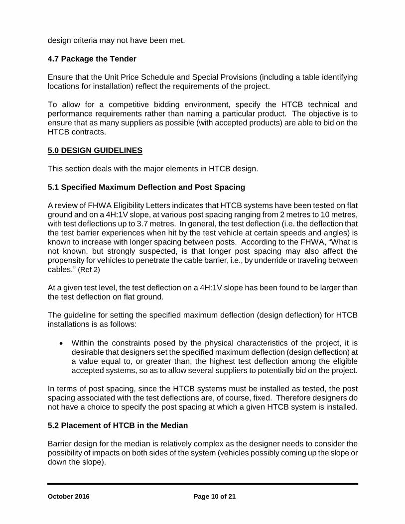
4.5 Specify the Design Criteria and Considerations It is recommended that design criteria and considerations unique to the project be tabulated for use in the design. The following is a list of items that are typically included (there may be other items), in a Design Criteria and Considerations Table.
DESIGN CRITERIA and CONSIDERATIONS TABLE (EXAMPLE ONLY)
Item Design Criterion
Installation Type (Roadside or Median) Cable Barrier Type (TL-3 or TL-4)
Road Width Sideslope
3-Cable or 4-Cable Hazard Offset
Specified Maximum Deflection (Design Deflection) Desired Deflection Space
Minimum Space Between Parallel Barrier Systems Transition Between Barrier Systems
Minimum Overlap Between Ends of Barrier Systems Locations Where Cable Barrier could replace Existing Barrier Systems
Offset from Edge of Roadway Placement on Horizontal Curves
Median Crossovers for Emergency and/or Maintenance Access At-Grade Intersections
Subsurface Investigation Choice of End Terminal Anchor
Possible Requirement for Selective Grading Other
4.6 Undertake the Design Considering the design criteria unique to the project and the physical characteristics of the project site, the detailed design can now be undertaken, including plans and cross sections. Designers should ensure appropriate documentation of where and why the
October 2016 Page 10 of 21
design criteria may not have been met. 4.7 Package the Tender Ensure that the Unit Price Schedule and Special Provisions (including a table identifying locations for installation) reflect the requirements of the project. To allow for a competitive bidding environment, specify the HTCB technical and performance requirements rather than naming a particular product. The objective is to ensure that as many suppliers as possible (with accepted products) are able to bid on the HTCB contracts. 5.0 DESIGN GUIDELINES This section deals with the major elements in HTCB design. 5.1 Specified Maximum Deflection and Post Spacing A review of FHWA Eligibility Letters indicates that HTCB systems have been tested on flat ground and on a 4H:1V slope, at various post spacing ranging from 2 metres to 10 metres, with test deflections up to 3.7 metres. In general, the test deflection (i.e. the deflection that the test barrier experiences when hit by the test vehicle at certain speeds and angles) is known to increase with longer spacing between posts. According to the FHWA, “What is not known, but strongly suspected, is that longer post spacing may also affect the propensity for vehicles to penetrate the cable barrier, i.e., by underride or traveling between cables.” (Ref 2) At a given test level, the test deflection on a 4H:1V slope has been found to be larger than the test deflection on flat ground. The guideline for setting the specified maximum deflection (design deflection) for HTCB installations is as follows:
• Within the constraints posed by the physical characteristics of the project, it is desirable that designers set the specified maximum deflection (design deflection) at a value equal to, or greater than, the highest test deflection among the eligible accepted systems, so as to allow several suppliers to potentially bid on the project.
In terms of post spacing, since the HTCB systems must be installed as tested, the post spacing associated with the test deflections are, of course, fixed. Therefore designers do not have a choice to specify the post spacing at which a given HTCB system is installed. 5.2 Placement of HTCB in the Median Barrier design for the median is relatively complex as the designer needs to consider the possibility of impacts on both sides of the system (vehicles possibly coming up the slope or down the slope).
October 2016 Page 11 of 21
There are several requirements or guidelines that need to be met when deciding where in the median the HTCB is to be placed. The main ones are discussed below. 5.2.1 Desirable Deflection Space Cable barriers can normally be hit from both sides when installed in the median of divided highways (unless there is another system that prevents impacts from the opposing direction of travel). Only one HTCB run is typically installed in a median to prevent median cross-over collisions. The HTCB must prevent intrusion of vehicles into the opposing travel lane. Impact to the cable system may occur on the front side (closest to the travel lane) or the back-side (furthest from the travel lane after crossing the centre of the median). The test deflection and post spacing documented in the FHWA Eligibility Letters are based on the HTCB system being tested on tangent in a controlled environment for the various proprietary products. The actual deflection may be greater under real life, site-specific conditions (i.e. larger vehicles, variable impact angles, higher operating speeds, soil type/conditions, installation on curves, etc.). Therefore, it is appropriate to provide a “desirable deflection space” consisting of the specified maximum deflection plus a safety margin between 1) the HTCB and the median side painted yellow shoulder lines in both directions; and 2) the HTCB and a median hazard if the HTCB is relied upon to protect vehicles from the hazard. The safety margin is to be determined by the Designer. Where practical, a greater safety margin may be desirable. In particular locations, where appropriate deflection cannot be achieved or the median geometry (such as sideslope or ditch width) is not appropriate for placement of a single barrier, two possible alternative solutions may be considered:
• One alternative is to install the HTCB on both sides of the median but this will double the cost. This will resolve the “back hit” issue (intrusion of opposing vehicles into the travel lane caused by the impact on the back-side after crossing the centre of the median).
• The second alternative is to reduce the specified maximum deflection (design deflection), particularly where there are physical hazards (bridge piers, overhead sign posts, steep slopes, opposing vehicles, etc.). Most HTCB suppliers have charts correlating post spacing and deflection; estimated by interpolation between test results at certain post spacing. Before applying these charts, designers should ensure that these interpolations are acceptable to FHWA.
Longitudinal traffic barrier systems that are more forgiving are preferred. If there are no constraints on a particular site or project (such as allowable deflection space), designers should consider increasing the specified maximum deflection (design deflection) to a value that will still provide protection from the hazard. This will make the system more forgiving. 5.2.2 HTCB Placement in Depressed Medians Designers should review the Alberta Transportation guidelines and drawings regarding HTCB installation in depressed medians, including guidelines about “off-limit” parts of the median where the HTCB should not be installed. Refer to drawings RDG-B2.1 through
October 2016 Page 12 of 21
RDG-B2.4, located in Appendix B2 of the Alberta Transportation "Roadside Design Guide". (Ref 3) When there is an elevation difference between the roadways on a divided highway, HTCB should typically be placed on the side of the median nearest the roadway with the higher elevation. Placement at Shoulder vs. Ditch Bottom Although installation of HTCB in the centre of the median ditch would tend to provide the largest desirable deflection space, the soils at the ditch bottom are often relatively less compacted than on the sideslope at the shoulder. Also, the ditches are subject to water accumulation and there are often structures in the median, such as catch basins or culvert outlets. The ditches are often uneven, with weak soil conditions and may require extra grading and compacting and a review of the overall drainage patterns. These factors tend to make the ditch installation of HTCB more expensive and the collision outcomes less predictable. The soils on side slopes are compacted, generally above the water table and, therefore, much stronger. Another disadvantage of the ditch location is that snow and ice may submerge all or part of the cable barrier, thus rendering it less effective. HTCB located near the shoulder is generally not affected by snow accumulation or drifting. The preferred HTCB location is at the top of the median side slope near the shoulder, subject to the Alberta Transportation guidelines listed below. HTCB should be installed in the ditch only when shoulder installations are not able to meet the desirable deflection space requirements. For ditch installations, the soil strength must be taken into account when designing the post foundations and end anchor foundations. Where the existing sideslopes are unsuitable to allow installation of the barrier in the preferred location near the top of the median sideslope, the option of selective or general re-grading should be considered. Installation on Median Sideslopes (6H:1V or Flatter) HTCB is designed for impact on front and back sides. Refer to Drawing RDG-B2.1 For depressed medians where the median slope is 6H:1V or flatter:
• the preferred location is near the shoulder (as discussed above) within 1.2 metres of the edge of pavement. This is to reduce the probability of vehicles over-riding the system;
• it is permitted to place the barrier down the sideslope provided it is not placed in the “no zone” (between 0.3 metres and 2.4 metres from the toe of slope). This is to reduce the probability of vehicles under-riding the system.
• it is permitted to place the barrier in the median ditch bottom provided it is not placed in the “no zone” (between 0.3 metres and 2.4 metres from the toe of slope). This pertains to a V-shaped ditch or a flat-bottom ditch that is wider than 2.4 metres. This is to reduce the probability of vehicles under-riding the system.
October 2016 Page 13 of 21
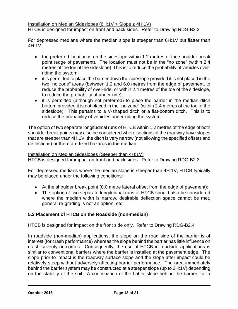
Installation on Median Sideslopes (6H:1V > Slope ≥ 4H:1V) HTCB is designed for impact on front and back sides. Refer to Drawing RDG-B2.2 For depressed medians where the median slope is steeper than 6H:1V but flatter than 4H:1V:
• the preferred location is on the sideslope within 1.2 metres of the shoulder break point (edge of pavement). The location must not be in the “no zone” (within 2.4 metres of the toe of the sideslope) This is to reduce the probability of vehicles over-riding the system;
• it is permitted to place the barrier down the sideslope provided it is not placed in the two “no zone” areas (between 1.2 and 6.0 metres from the edge of pavement, to reduce the probability of over-ride, or within 2.4 metres of the toe of the sideslope, to reduce the probability of under-ride);
• it is permitted (although not preferred) to place the barrier in the median ditch bottom provided it is not placed in the “no zone” (within 2.4 metres of the toe of the sideslope). This pertains to a V-shaped ditch or a flat-bottom ditch. This is to reduce the probability of vehicles under-riding the system.
The option of two separate longitudinal runs of HTCB within 1.2 metres of the edge of both shoulder break points may also be considered where sections of the roadway have slopes that are steeper than 4H:1V, the ditch is very narrow (not allowing the specified offsets and deflections) or there are fixed hazards in the median. Installation on Median Sideslopes (Steeper than 4H:1V) HTCB is designed for impact on front and back sides. Refer to Drawing RDG-B2.3 For depressed medians where the median slope is steeper than 4H:1V, HTCB typically may be placed under the following conditions:
• At the shoulder break point (0.0 metre lateral offset from the edge of pavement); • The option of two separate longitudinal runs of HTCB should also be considered
where the median width is narrow, desirable deflection space cannot be met, general re-grading is not an option, etc.
5.3 Placement of HTCB on the Roadside (non-median) HTCB is designed for impact on the front side only. Refer to Drawing RDG-B2.4 In roadside (non-median) applications, the slope on the road side of the barrier is of interest (for crash performance) whereas the slope behind the barrier has little influence on crash severity outcomes. Consequently, the use of HTCB in roadside applications is similar to conventional barriers where the barrier is installed at the pavement edge. The slope prior to impact is the roadway surface slope and the slope after impact could be relatively steep without adversely affecting barrier performance. The area immediately behind the barrier system may be constructed at a steeper slope (up to 2H:1V) depending on the stability of the soil. A continuation of the flatter slope behind the barrier, for a
October 2016 Page 14 of 21
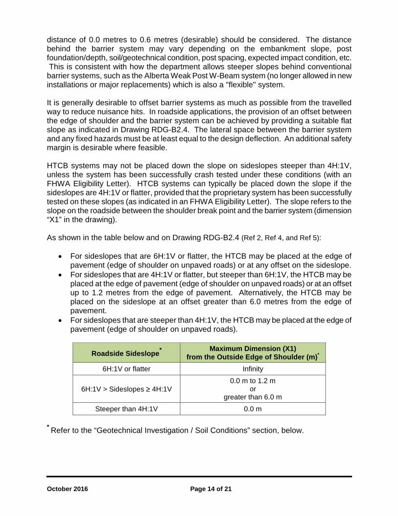
distance of 0.0 metres to 0.6 metres (desirable) should be considered. The distance behind the barrier system may vary depending on the embankment slope, post foundation/depth, soil/geotechnical condition, post spacing, expected impact condition, etc. This is consistent with how the department allows steeper slopes behind conventional barrier systems, such as the Alberta Weak Post W-Beam system (no longer allowed in new installations or major replacements) which is also a "flexible" system. It is generally desirable to offset barrier systems as much as possible from the travelled way to reduce nuisance hits. In roadside applications, the provision of an offset between the edge of shoulder and the barrier system can be achieved by providing a suitable flat slope as indicated in Drawing RDG-B2.4. The lateral space between the barrier system and any fixed hazards must be at least equal to the design deflection. An additional safety margin is desirable where feasible. HTCB systems may not be placed down the slope on sideslopes steeper than 4H:1V, unless the system has been successfully crash tested under these conditions (with an FHWA Eligibility Letter). HTCB systems can typically be placed down the slope if the sideslopes are 4H:1V or flatter, provided that the proprietary system has been successfully tested on these slopes (as indicated in an FHWA Eligibility Letter). The slope refers to the slope on the roadside between the shoulder break point and the barrier system (dimension “X1” in the drawing). As shown in the table below and on Drawing RDG-B2.4 (Ref 2, Ref 4, and Ref 5):
• For sideslopes that are 6H:1V or flatter, the HTCB may be placed at the edge of pavement (edge of shoulder on unpaved roads) or at any offset on the sideslope.
• For sideslopes that are 4H:1V or flatter, but steeper than 6H:1V, the HTCB may be placed at the edge of pavement (edge of shoulder on unpaved roads) or at an offset up to 1.2 metres from the edge of pavement. Alternatively, the HTCB may be placed on the sideslope at an offset greater than 6.0 metres from the edge of pavement.
• For sideslopes that are steeper than 4H:1V, the HTCB may be placed at the edge of pavement (edge of shoulder on unpaved roads).
Roadside Sideslope* Maximum Dimension (X1) from the Outside Edge of Shoulder (m)*
6H:1V or flatter Infinity
6H:1V > Sideslopes ≥ 4H:1V 0.0 m to 1.2 m
or greater than 6.0 m
Steeper than 4H:1V 0.0 m * Refer to the “Geotechnical Investigation / Soil Conditions” section, below.
October 2016 Page 15 of 21
5.4 Placement of HTCB on Undivided Highways – Considering Wide Loads, Farm Equipment and Nuisance Hits In the interests of accommodating wide loads, farm equipment and reducing the frequency of nuisance hits in general, it is desirable to set the HTCB as far back from the travelled way as practical. This provides more lateral space and reduced barrier height compared to an installation at the edge of roadway. The needs and practicality are influenced by the roadway width, sideslope and expected type of oversized vehicles. Designers should assess the need to accommodate oversized loads based on current and anticipated traffic for the roadway. Flexibility available to the designer includes:
• the ability to offset the HTCB down the slope, if the existing slope is 4H:1V or flatter; • for existing sideslopes steeper than 4H:1V, the ability to modify the sideslope to
4H:1V or flatter, in order to offset the HTCB down the slope. The designer should consider a flatter slope in order to maximize the offset of the HTCB;
• the ability to flatten the upper portion of the sideslope to 4H:1V or flatter with a steeper slope behind the barrier;
• the ability to specify a HTCB that is 840 mm in height, or less. Both the height of a barrier and the lateral offset are factors that affect the ability to accommodate wide loads and farm equipment and, therefore, designers are advised to follow the procedure indicated below, together with normal engineering judgment: If the sideslopes on a roadway (either divided or undivided) are 4H:1V or flatter, or can be modified to obtain this slope, it is desirable to offset the barrier as much as permitted from the roadway shoulder, while still providing the deflection room to any fixed hazards. A slope steeper than 4H:1V behind the barrier is permitted, as long as the slope is clear of hazards within the barrier deflection. If the sideslopes on a roadway are steeper than 4H:1V and cannot be flattened due to constraints, the HTCB shall be placed at the shoulder break point. This is essentially the same location that a Strong Post W-Beam system would normally be placed. If the roadway width is 9 metres or less and a decision has been made not to flatten the sideslopes based on economics or other constraints, the designer should specify that the HTCB be not taller than 840 mm. This will minimize the likelihood of nuisance hits from wide load vehicles; including farm equipment. Alberta Transportation has various HTCB products available for use that meet this height criterion. They can be found on the AT Products List: http://www.transportation.alberta.ca/Content/docType253/Production/TrafficControlDevices.pdf In addition to the products on the AT Products List, some manufacturers have different models that have been developed and are acceptable for use based on the different scenarios mentioned above. Some of these systems are rated TL-4 and some TL-3. Some have 4 cables and some have 3 cables. Refer to the Alberta Transportation “HTCB Basic Dimensions Drawing” (Ref 6) at:
October 2016 Page 16 of 21
http://www.transportation.alberta.ca/Content/docType233/Production/HTCBDimensions.pdf for a list of HTCB products highlighting the various characteristics. If a system has “(4:1)” specified, it may be used on a sideslope of 4H:1V or flatter. If a system does not have “(4:1)” specified, it is to be used for 6H:1V, or flatter, applications. The slope refers to the slope the vehicle is travelling on in advance of impact. The slope behind the barrier is not stipulated. 5.5 Placement of HTCB in the Vicinity of a Bridgerail Transition When barrier connection to a bridgerail is required, a transitional barrier is used to allow for the transition from a rigid barrier (bridgerail) to a semi-rigid barrier (Thrie Beam, which then transitions to a Strong Post W-Beam). See http://www.transportation.alberta.ca/4855.htm for various Alberta Transportation bridgerail transition drawings. If HTCB is placed in the vicinity of the bridgerail transition, the transition between the flexible HTCB and the semi-rigid Strong Post W-Beam can be achieved in two ways:
• directly connecting the HTCB to the semi-rigid barrier; • partial overlapping of the HTCB with the semi-rigid barrier.
For cases where connecting the HTCB to a Strong Post W-Beam is used, proprietary systems that have been issued an FHWA Eligibility Letter (and are also listed on the AT Products List) may be used and the proprietary drawings must be referred to. These drawings can be found on the Federal Highway Administration website at: http://safety.fhwa.dot.gov/roadway_dept/policy_guide/road_hardware/barriers/ The connection of the HTCB to the Strong Post W-Beam must occur outside of the Bridgerail Transition Zone, as indicated on the AT Bridgerail Transition Drawings. Refer to the “Overlapping Barrier Systems” section (below) for best practices related to the partial overlapping option. 5.6 Placement on Curved Horizontal Alignments Median and roadside HTCB installed on horizontal curves, if hit on the convex side, can be expected to have an increased deflection. Reducing the post spacing may be an effective countermeasure. Designers should be cautious about using HTCB on convex curves, particularly if the radius is less than 160 metres. Designers should review the FHWA Eligibility Letters and the manufacturers and/or vendor’s product details and specifications with respect to post spacing and test deflection. As indicated previously, the test deflection in the FHWA Eligibility Letters are normally based on the system being tested on tangent in a controlled environment. Actual test documentation on the post spacing and its effect on the test deflection on horizontal curves may not be available. Designers may have to

October 2016 Page 17 of 21
review and rely on the supplier’s interpolations of post spacing vs. deflection, as indicated in the FHWA Eligibility Letters, along with using engineering judgement, to determine the suitable post spacing. There is generally a higher frequency of vehicles inadvertently leaving the roadway on the outside of horizontal curves than the inside of horizontal curves. To reduce the frequency of low severity (nuisance) hits, the preferred location of a median HTCB is toward the inside of the outermost horizontal alignment of a divided roadway. Refer to Figure 1.
Figure 1: HTCB Placement on Horizontal Curves
5.7 Placement on Curved Vertical Alignments HTCB placement may be restricted with respect to minimum vertical curvature. Depending on the proprietary system chosen, minimum allowable curvature values may vary. Designers should review the FHWA Eligibility Letters and the manufacturer’s product information and specifications for available details on minimum K values. There may be restrictions on vertical sag alignments with small K values. Report No. FHWA/TX-10/0-5609-2, “Development of Guidelines for Cable Median Barrier Systems in Texas” (Ref 7) indicates, “According to Alberson et al., some of the cable barrier systems have limited upward capability for carrying vertical loads. As such, vertical sag curves may allow the wire ropes to lift or partially lift out of the post and increase the likelihood of vehicle underride. On socketed systems, there is generally no attachment of the posts to the sockets. Therefore, if the wire ropes are more firmly attached to the post, they may lift the post out of the socket on vertical sag curves and increase the opportunity for vehicle underride.” 5.8 End Treatment or Anchors Alberta Transportation has included some proprietary HTCB anchor systems as separate products on the Products List. These are being evaluated and may be accepted as “proven” when the assessment has been completed. The use of these proprietary products may negate the need for on-site soil testing and local engineering analysis.
October 2016 Page 18 of 21
Products are to be used according to the conditions indicated in the Products List. End treatments that are exposed to on-coming traffic must terminate with a crashworthy end treatment that meets Test Level 3 (TL-3) crash test requirements of NCHRP 350 or MASH 2009. HTCB end terminals are proprietary. 5.9 Anchor Spacing - Run Length The distance between anchor terminals is commonly referred to as a cable run or run length. In theory, there is no limit to the length of a single uninterrupted run of a cable barrier. Longer cable runs, however, require more effort to tension and re-tension, and there may be more maintenance or replacement difficulties with barrier cables that are very long. The presence of bridge structures, at-grade intersections and emergency maintenance crossovers act as obvious breaks in cable barrier runs. A recommended maximum desired uninterrupted run of +/- 5 km was used for the median HTCB installation on Highway 2 from Airdrie to Red Deer. Where a break or interruption in the cable run is required to meet the maximum desired uninterrupted run (determined by the manufacturer) and where there is no convenient location (intersection or crossover) then a break and overlap in the HTCB alignment is required. Refer to the “Overlapping Barrier Systems” section for overlap requirements. For median at-grade intersections and emergency/maintenance crossovers, AT’s practice has been to locate anchor end terminals a minimum of 15 metres from the edge of the paved intersection or crossover to provide adequate space for snow storage. 5.10 Overlapping Barrier Systems Although, physically connecting the two different types of barriers may produce a smoother transition, the efforts to retrofit an existing barrier system to support the required cable tension may be quite extensive and require additional maintenance and increased time to repair, if impacted. Consequently, it is generally preferred to overlap the systems where feasible rather than connecting them. There are two types of overlapping systems; a full overlap and a partial overlap.
• An example of a full overlap is where an existing offset barrier system (i.e. concrete, W-Beam or other) must remain in place at a hazard (i.e. overhead sign post, bridge pier, sensor pole, etc.). Then a longer HTCB is installed (often as a median barrier) that continues past, along the shoulder of the roadway, to retain continuity of the HTCB on either side of the hazard. The HTCB overlaps the existing system without touching, thereby providing two barriers for the overlap length. For a full overlap where the HTCB runs parallel to an existing barrier system, the HTCB is providing double protection with an energy absorbing function. It is desirable (but not essential) that the lateral spacing (offset) between the HTCB and the other barrier system is sufficient to allow for the design deflection of the HTCB, so that collisions will normally require repair to just one system. If the area is constrained, the designer may use judgment to accept a smaller lateral offset to
October 2016 Page 19 of 21
achieve a better overall design. It is also desirable that the lateral spacing between the cable barrier and existing barrier be enough to prevent the posts of the HTCB from becoming a hazard. Enough lateral space should be provided so that, in the event the HTCB is knocked down by a vehicle, the posts do not impact the adjacent, more rigid barrier system. Typically, the minimum lateral spacing between the systems should be in excess of the HTCB post height for the various proprietary products. The post heights indicated in the Alberta Transportation “HTCB Basic Dimensions Drawing” (Ref 6) vary between 780mm and 1257mm.
• An example of a partial overlap consists of a HTCB transitioning to a Strong Post W-Beam (which then may transition to a Thrie Beam and then to a bridgerail). The effective portion of the HTCB must completely overlap the ineffective portion of the Strong Post W-Beam end treatment. In general, the length of the anchor end terminals, where the cables are not parallel to the ground (for the HTCB) and crash-worthy end treatments (for the W-Beam) are not part of the effective portion of the barrier. Refer to the manufacturer’s drawings and specifications regarding where the effective portion of the barrier begins. For a partial overlap, it may not be possible to provide an offset between the HTCB and the other barrier system that is sufficient to allow for the design deflection of the HTCB or is in excess of the HTCB post height. If the area is constrained, the designer may use judgment to accept a smaller lateral offset to achieve a better overall design. Where the HTCB is upstream of a segment of existing barrier (i.e. upstream of the crashworthy, flare and/or turndown end treatment), the HTCB should overlap in front of the existing system. The position of the HTCB is between the paved shoulder and the face of the existing barrier system. Where the HTCB is downstream of a segment of existing barrier, the HTCB should be positioned behind the existing barrier system.
Where existing barriers are to remain in place, designers should also assess if the existing barrier system is in accordance with Alberta Transportation’s current guidelines. The assessment may recommend reconstruction, replacement and/or improvements to the existing barrier system. 5.11 Conditions Where Cable Barrier May Replace Existing, Less Flexible Barriers In general, HTCB may replace existing barriers where the HTCB system can maintain the desired alignment along the shoulder and bypass an existing hazard with a spacing (offset) greater than or equal to the desirable deflection space (specified maximum deflection plus a safety margin) from the hazard. 5.12 Geotechnical Investigation / Soil Conditions The on-site soil condition can be different than the soil condition used in the cable barrier tests on which the FHWA acceptances are based.
October 2016 Page 20 of 21
Geotechnical testing (soil testing) and site-specific engineering design is not required for products (line posts, terminal posts and anchor systems) listed on the AT Products List except in the following cases:
• Where it is a replacement of an existing HTCB where the existing anchors were distressed, heaved or displaced a significant amount (as identified by the Consultant); or
• Unusual foundation conditions are anticipated, such as areas where obvious rock exposures are present (rock cuts) or wet and soft areas (muskeg).
Where anchor designs are required, geotechnical investigations, that include the nature of the drainage, must be carried out during the preliminary design and/or early detailed design stages. The results are included in the tender package. The ditch may be subject to periodic flooding and/or wet soil conditions, which must be taken into account in the design. The Contractor is responsible for the design and installation of the end treatments or anchors to meet the soil conditions on the site. The design shall be certified by a Professional Engineer experienced in structural/foundation design and registered with APEGA. 6.0 EFFECTIVE DATE The guidelines as indicated in this Bulletin are to be implemented immediately as per the usual practice. Original Date: February 7, 2012 Revision Date 1: April 5, 2012 Rewrite Date: October 27, 2016 7.0 CONTACT Bill Kenny (780-415-1048) Technical Standards Branch, Alberta Transportation Peter Mah (780-427-7129) Technical Standards Branch, Alberta Transportation 8.0 REFERENCES Ref 1) Alberta Transportation, “Roadside Design Guide”, November, 2007
http://www.transportation.alberta.ca/3451.htm
Ref 2) FHWA, “Information Memorandum: Cable Barrier Considerations”, July 20, 2007 http://safety.fhwa.dot.gov/roadway_dept/policy_guide/road_hardware/policy_memo/memo072007/
Ref 3) Alberta Transportation, "Roadside Design Guide", November, 2007 Appendix B2- Reference Drawings, High Tension Cable Barrier
RDG-B2.1 (rev 1) RDG-B2.2 (rev 1) RDG-B2.3 (rev 1) RDG-B2.4 (rev 2)
Typical HTCB Median Installation, Slopes 6H:1V or Flatter Typical HTCB Median Installation, 6H:1V >Slopes~ 4H:1V Typical HTCB Median Installation, Slopes Steeper than 4H:1V Typical HTCB Roadside Installation
http://www.transportation.alberta.ca/Content/docType233/Production/RDG-APPENDIX-B4.pdf
Ref 4) NCHRP Report 711: "Guidance for the Selection, Use, and Maintenance of Cable Barrier Systems', Section 6.3 Cable Barrier Guidelines.
http://www.trb.org/main/blurbs/167753.aspx
Ref 5) FWHA, "Cable Barriers- Design Standard and Placement Considerations', September 30, 2015
http://safety.fhwa.dot.gov/roadway dept/policy guide/road hardware/ctrmeasures/cable barriers/#n2
Ref 6) Alberta Transportation, "HTCB Basic Dimensions Drawing'
http://www.transportation.alberta.ca/Content/docType233/Production/HTCBDimensions.pdf
Ref 7) FWHA/Texas Dot, Report No. FHWA/TX-10/0-5609-2, "Development of Guidelines for Cable Median Barrier Systems in Texas', 2009
http://tti. tam u. edu/docu ments/0-5609-2. pdf
Recommended:
Bill Kenny, P. Eng. Director, Design, Project Management and Training
Date 27 Ocf 1i(.
Approved:
. :22 lJ~ .. ~~ Des Williamson, P. Eng. Acting Executive Director, Technical Standards Branch
Date UJ/4 · /0 r Z-7
October 2016 Page 21 of 21