Embed Size (px)
Citation preview
AppC_Ch9-DesignClac_8.9.10 Chapter 9 Electrical Design
2010 Edition SPU Design Standards and Guidelines 9C-i
Appendix C Design Calculations for
Electrical Design

Appendix C Design Calculations
9C-ii 2010 Edition SPU Design Standards and Guidelines
AppC_Ch9-DesignClac_8.9.10 Chapter 9 Electrical Design
2010 Edition SPU Design Standards and Guidelines 9C-iii
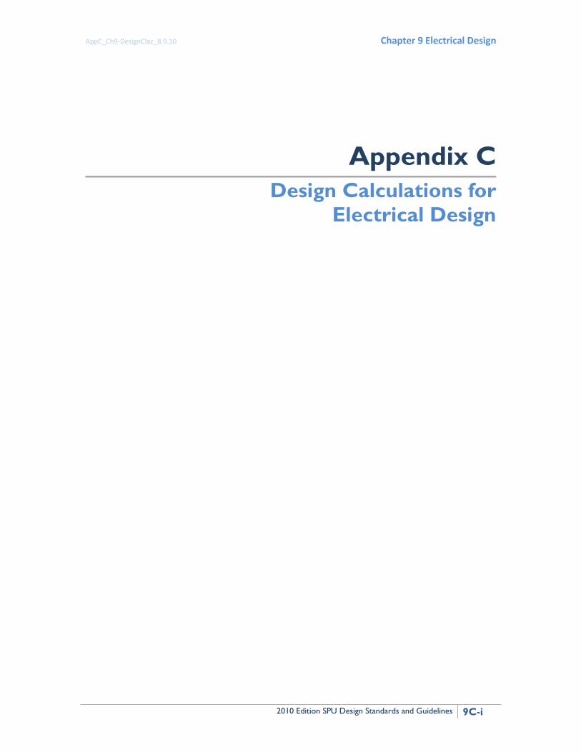
Contents Appendix C Design Calculations for Electrical Design .................................................................... 1
1.1 Introduction ..................................................................................................................... 1 1.2 Software .......................................................................................................................... 1 1.3 Calculation Matrix ........................................................................................................... 2 1.4 Basic Requirements for Electrical Calculations ............................................................... 4 1.5 Basic Electrical Engineering Formulas ............................................................................. 4
1.5.1 List of Symbols ......................................................................................................... 4 1.5.2 Direct Current (DC) Formulas .................................................................................. 5 1.5.3 Alternating Current (AC) Single Phase ..................................................................... 5 1.5.4 Alternating Current (AC), Three-Phase .................................................................... 5 1.5.5 Motors ..................................................................................................................... 6 1.5.6 Power Factor Correction ......................................................................................... 6
1.6 Sample Calculations ......................................................................................................... 7 1.6.1 Load ......................................................................................................................... 7 1.6.2 Generator Sizing ...................................................................................................... 7 1.6.3 Conductor Size, General .......................................................................................... 9 1.6.4 Conduit Size and Fill ............................................................................................... 13 1.6.5 Motor Branch Circuit ............................................................................................. 14 1.6.6 Power Factor Correction Capacitors...................................................................... 16 1.6.7 Transformer Primary and Secondary Conductors ................................................. 18 1.6.8 Voltage Drop .......................................................................................................... 20 1.6.9 Short Circuit ........................................................................................................... 22 1.6.10 Lighting .................................................................................................................. 23 1.6.11 Grounding .............................................................................................................. 29 1.6.12 Cable Pulling Tension ............................................................................................. 29 1.6.13 Equipment Heat Loads .......................................................................................... 30
List of Tables Table C-1 Calculations for Electrical Design .................................................................................... 2 Table C-2 NEC References for Conductor Sizing .............................................................................. 9 Table C-3 Coefficient of Utilization Zonal Cavity Method ............................................................. 25 Table C-4 Candlepower Distribution Curve ................................................................................... 27 Table C-5 Losses in Electrical Equipment ...................................................................................... 30 List of Examples Example 1 Motors ........................................................................................................................... 6 Example 2 Conductor Size No. 1 .................................................................................................... 11 Example 3 Conductor Size No. 2 .................................................................................................... 12 Example 4 Conductor Size No. 3 .................................................................................................... 12 Example 5 Conductor Size No. 3 .................................................................................................... 13 Example 6 Conduit Size and Fill No. 1 ........................................................................................... 13 Example 7 Conduit Size and Fill No. 2 ........................................................................................... 14 Example 8 Motor Branch Circuit No. 1 .......................................................................................... 15 Example 9 Motor Branch Circuit No. 2 .......................................................................................... 16 Example 10 Power Factor No. 1 .................................................................................................... 17 Example 11 Power Factor Correction Capacitor No. 2 .................................................................. 18 Example 12 Transformer Primary and Secondary Conductors No. 1 ............................................ 18

Appendix C Design Calculations
9C-iv 2010 Edition SPU Design Standards and Guidelines
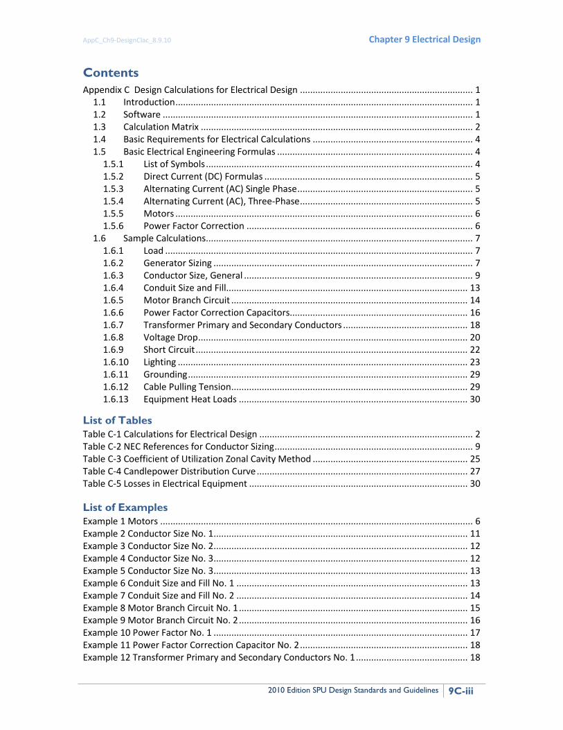
Example 13 Transformer Primary and Secondary Conductors No. 2 ............................................ 19 Example 14 Transformer Primary and Secondary Conductors No. 3 ............................................ 20 Example 15 Feeder and Branch Circuits ........................................................................................ 21 Example 16 Short Circuit ............................................................................................................... 22 Example 17 Lighting No 1: Lumen or Zonal Cavity Method .......................................................... 24 Example 18 Lighting No 2: Point by Point Calculation .................................................................. 27

AppC_Ch9-DesignClac_8.9.10 Chapter 9 Electrical Design
2010 Edition SPU Design Standards and Guidelines 9C-1
APPENDIX C Design Calculations for Electrical Design This appendix presents standards and guidelines for electrical design calculations for SPU projects.
1.1 INTRODUCTION Design calculations establish minimum guidelines and requirements for generating electrical calculations on projects. Electrical calculations should be made for all SPU projects that include electrical components and should be filed in the project notebook. Design calculations may be made either manually or by SPU-approved computer programs. At a minimum, the following types of calculations should be made where applicable:
• Load calculations
• Conductor sizing
• Conduit sizing
• Motor branch circuit sizing
• Power factor improvement
• Transformer primary and secondary circuit sizing
• Voltage drop
• Motor starting voltage dip
• Short circuit analysis
• Lighting levels
• Grounding in substations where step potentials are of concern
• Harmonic distortion analysis
• Cable pulling calculations
• Generator capability/motor starting.
1.2 SOFTWARE The electrical design engineer must use only SPU-approved electrical analysis software. The results should be validated with a hand calculation or order of magnitude estimate. Some SPU-approved software tools are:
• SKM Power Tools for Windows (PTW) software. It includes a basic tool, DAPPER (load current, voltage drop, conductor sizing, etc) and several specialized tools such as HI_WAVE (harmonic analysis) and CAPTOR (circuit breaker coordination and settings)
Appendix C Design Calculations
9C-2 2010 Edition SPU Design Standards and Guidelines
• Cummins Power Suite for sizing emergency generators
• CenterONE available from Rockwell Automation for laying out motor control centers
Spreadsheets may also be used to perform basic electrical load calculations with programs such as Microsoft EXCEL.
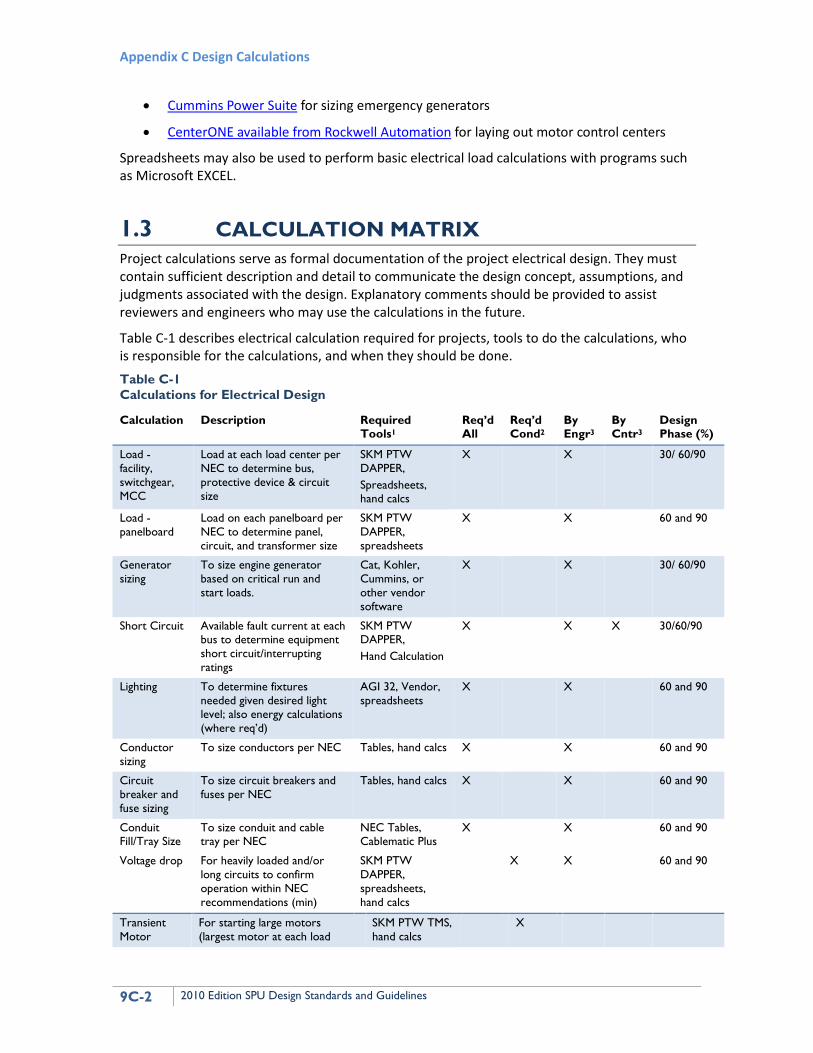
1.3 CALCULATION MATRIX Project calculations serve as formal documentation of the project electrical design. They must contain sufficient description and detail to communicate the design concept, assumptions, and judgments associated with the design. Explanatory comments should be provided to assist reviewers and engineers who may use the calculations in the future.
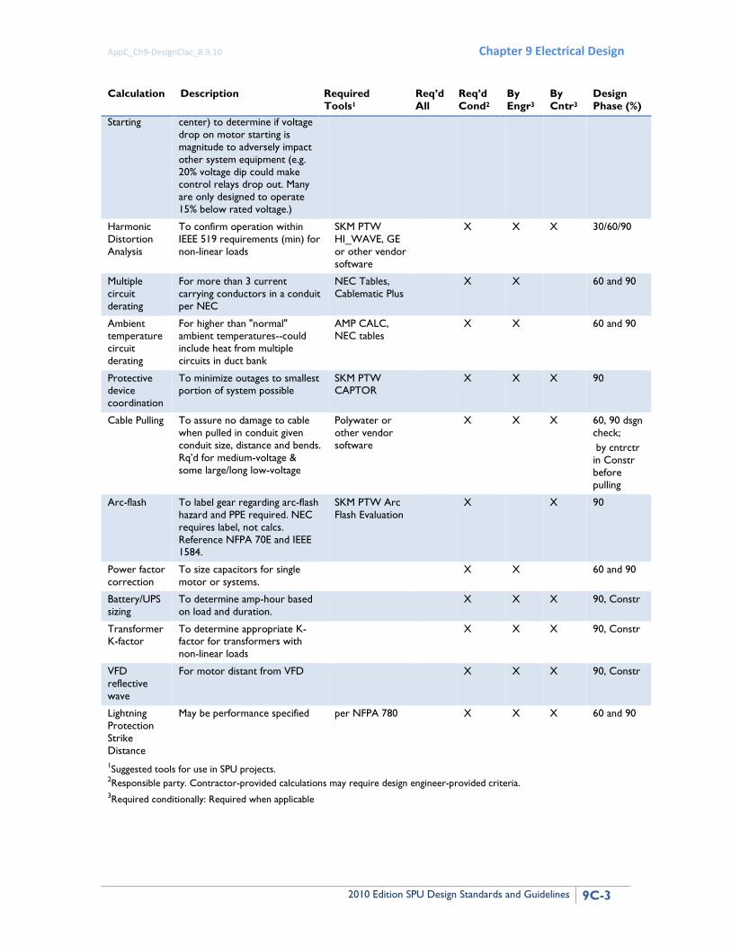
Table C-1 describes electrical calculation required for projects, tools to do the calculations, who is responsible for the calculations, and when they should be done. Table C-1 Calculations for Electrical Design
Calculation Description Required Tools1
Req’d All
Req’d Cond2
By Engr3
By Cntr3
Design Phase (%)
Load - facility, switchgear, MCC
Load at each load center per NEC to determine bus, protective device & circuit size
SKM PTW DAPPER, Spreadsheets, hand calcs
X X 30/ 60/90
Load - panelboard
Load on each panelboard per NEC to determine panel, circuit, and transformer size
SKM PTW DAPPER, spreadsheets
X X 60 and 90
Generator sizing
To size engine generator based on critical run and start loads.
Cat, Kohler, Cummins, or other vendor software
X X 30/ 60/90
Short Circuit Available fault current at each bus to determine equipment short circuit/interrupting ratings
SKM PTW DAPPER, Hand Calculation
X X X 30/60/90
Lighting To determine fixtures needed given desired light level; also energy calculations (where req’d)
AGI 32, Vendor, spreadsheets
X X 60 and 90
Conductor sizing
To size conductors per NEC Tables, hand calcs X X 60 and 90
Circuit breaker and fuse sizing
To size circuit breakers and fuses per NEC
Tables, hand calcs X X 60 and 90
Conduit Fill/Tray Size
To size conduit and cable tray per NEC
NEC Tables, Cablematic Plus
X X 60 and 90
Voltage drop For heavily loaded and/or long circuits to confirm operation within NEC recommendations (min)
SKM PTW DAPPER, spreadsheets, hand calcs
X X 60 and 90
Transient Motor
For starting large motors (largest motor at each load
SKM PTW TMS, hand calcs
X
AppC_Ch9-DesignClac_8.9.10 Chapter 9 Electrical Design
2010 Edition SPU Design Standards and Guidelines 9C-3
Calculation Description Required Tools1
Req’d All
Req’d Cond2
By Engr3
By Cntr3
Design Phase (%)
Starting center) to determine if voltage drop on motor starting is magnitude to adversely impact other system equipment (e.g. 20% voltage dip could make control relays drop out. Many are only designed to operate 15% below rated voltage.)
Harmonic Distortion Analysis
To confirm operation within IEEE 519 requirements (min) for non-linear loads
SKM PTW HI_WAVE, GE or other vendor software
X X X 30/60/90
Multiple circuit derating
For more than 3 current carrying conductors in a conduit per NEC
NEC Tables, Cablematic Plus
X X 60 and 90
Ambient temperature circuit derating
For higher than "normal" ambient temperatures--could include heat from multiple circuits in duct bank
AMP CALC, NEC tables
X X 60 and 90
Protective device coordination
To minimize outages to smallest portion of system possible
SKM PTW CAPTOR
X X X 90
Cable Pulling To assure no damage to cable when pulled in conduit given conduit size, distance and bends. Rq’d for medium-voltage & some large/long low-voltage
Polywater or other vendor software
X X X 60, 90 dsgn check; by cntrctr in Constr before pulling
Arc-flash To label gear regarding arc-flash hazard and PPE required. NEC requires label, not calcs. Reference NFPA 70E and IEEE 1584.
SKM PTW Arc Flash Evaluation
X X 90
Power factor correction
To size capacitors for single motor or systems.
X X 60 and 90
Battery/UPS sizing
To determine amp-hour based on load and duration.
X X X 90, Constr
Transformer K-factor
To determine appropriate K-factor for transformers with non-linear loads
X X X 90, Constr
VFD reflective wave
For motor distant from VFD X X X 90, Constr
Lightning Protection Strike Distance
May be performance specified per NFPA 780 X X X 60 and 90
1Suggested tools for use in SPU projects. 2Responsible party. Contractor-provided calculations may require design engineer-provided criteria. 3Required conditionally: Required when applicable
Appendix C Design Calculations
9C-4 2010 Edition SPU Design Standards and Guidelines
1.4 BASIC REQUIREMENTS FOR ELECTRICAL CALCULATIONS
The following are SPU basic requirements for electrical calculations:
1. Non-computer generated calculations must be on standard calculations sheets with the heading completely filled out.
2. Calculations generated by computer programs must conform with the following procedures:
a. Include all heading information on each sheet
b. Insert comments wherever possibly to clarify concepts and actions taken in the computer input
c. Provide clear documentation of electrical geometry, support conditions, load application, and load requirements
d. Where practical, provide sketch of model indicting nodes, materials, connectivity, etc.
e. Provide electronic copy on CD or other suitable device of analysis input and output with hard copy calculations.
f. Provide manual checks of pertinent results (e.g. service size, main feeder voltage drop) for computer generated output.
1.5 BASIC ELECTRICAL ENGINEERING FORMULAS
This section describes basic electrical engineering formulas for creating design calculations.
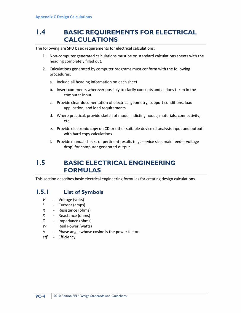
1.5.1 List of Symbols V - Voltage (volts) I - Current (amps) R - Resistance (ohms) X - Reactance (ohms) Z - Impedance (ohms) W Real Power (watts) θ - Phase angle whose cosine is the power factor eff - Efficiency
AppC_Ch9-DesignClac_8.9.10 Chapter 9 Electrical Design
2010 Edition SPU Design Standards and Guidelines 9C-5
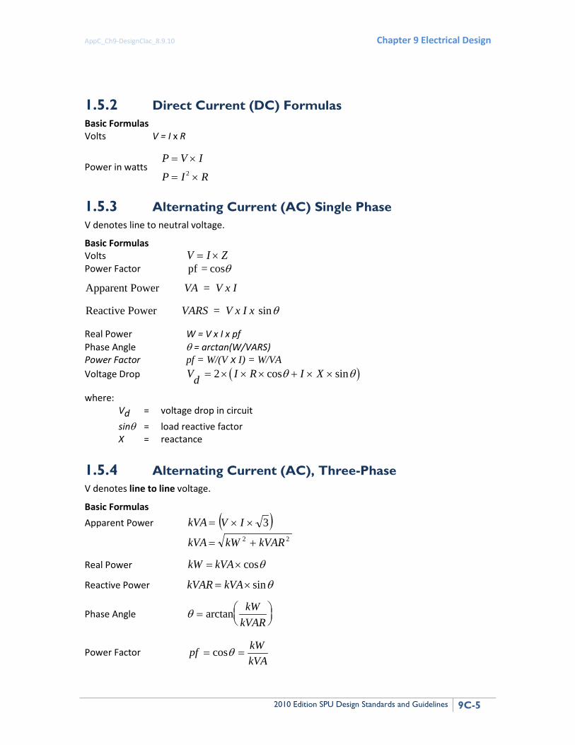
1.5.2 Direct Current (DC) Formulas Basic Formulas Volts V = I x R
Power in watts P V I
P I R
= ×
= ×2
1.5.3 Alternating Current (AC) Single Phase V denotes line to neutral voltage.
Basic Formulas Volts V I Z= × Power Factor θcos = pf
Apparent Power =
Reactive Power =
VA V x I
VARS V x I x sinθ
Real Power W = V x I x pf Phase Angle θ = arctan(W/VARS) Power Factor pf = W/(V x I) = W/VA Voltage Drop ( )Vd I R I X= × × × + × ×2 cos sinθ θ
where: Vd = voltage drop in circuit sinθ = load reactive factor X = reactance
1.5.4 Alternating Current (AC), Three-Phase V denotes line to line voltage.
Basic Formulas Apparent Power =kVA ( )3×× IV
22 kVARkWkVA +=
Real Power θcos×= kVAkW
Reactive Power kVAR kVA= × sinθ
Phase Angle θ =
arctan kWkVAR
Power Factor kVAkWpf == θcos
Appendix C Design Calculations
9C-6 2010 Edition SPU Design Standards and Guidelines
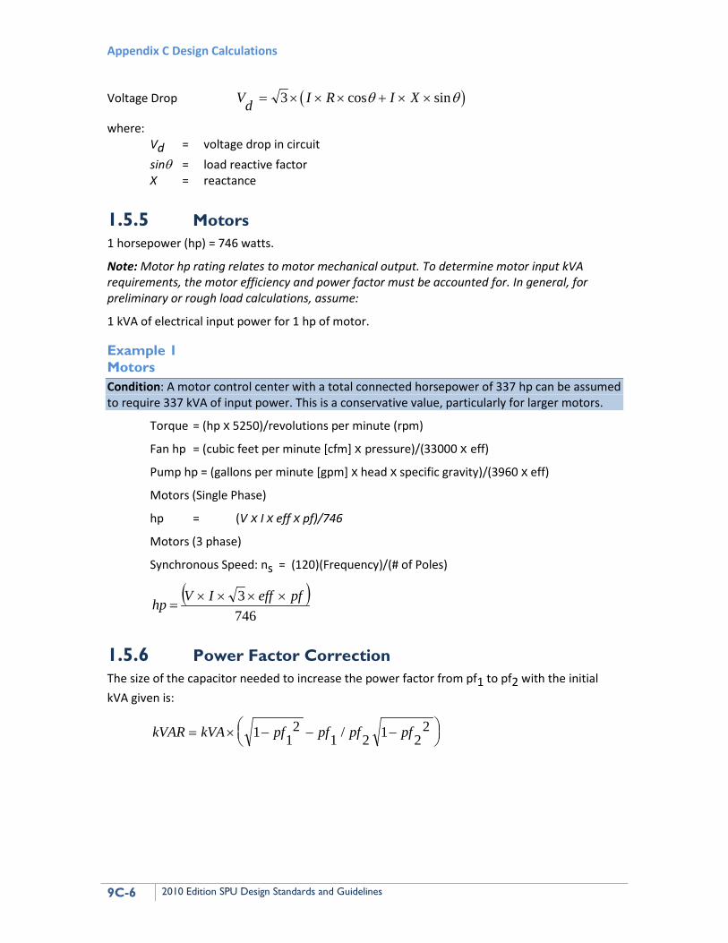
Voltage Drop ( )Vd I R I X= × × × + × ×3 cos sinθ θ
where: Vd = voltage drop in circuit sinθ = load reactive factor X = reactance
1.5.5 Motors 1 horsepower (hp) = 746 watts.
Note: Motor hp rating relates to motor mechanical output. To determine motor input kVA requirements, the motor efficiency and power factor must be accounted for. In general, for preliminary or rough load calculations, assume:
1 kVA of electrical input power for 1 hp of motor.
Example 1 Motors Condition: A motor control center with a total connected horsepower of 337 hp can be assumed to require 337 kVA of input power. This is a conservative value, particularly for larger motors.
Torque = (hp x 5250)/revolutions per minute (rpm)
Fan hp = (cubic feet per minute [cfm] x pressure)/(33000 x eff)
Pump hp = (gallons per minute [gpm] x head x specific gravity)/(3960 x eff)
Motors (Single Phase)
hp = (V x I x eff x pf)/746
Motors (3 phase)
Synchronous Speed: ns = (120)(Frequency)/(# of Poles)
( )7463 pfeffIVhp ××××
=
1.5.6 Power Factor Correction The size of the capacitor needed to increase the power factor from pf1 to pf2 with the initial kVA given is:
kVAR kVA pf pf pf pf= × − − −
1 12
1 2 1 22/
AppC_Ch9-DesignClac_8.9.10 Chapter 9 Electrical Design
2010 Edition SPU Design Standards and Guidelines 9C-7
1.6 SAMPLE CALCULATIONS This section presents sample calculations for electrical design.
1.6.1 Load Load calculations should be made using applicable sections of NEC Articles 220, 430, and other sections of the NEC. The following load calculations should generally be used for sizing:
• Feeder conductors and protective devices
• Transformers
• Panelboard and switchboard main busses
• Motor control center components
• Service entrance devices and conductors
Load calculations must include all loads. They should be made by summing all of the loads (using appropriate diversity factors allowed by NEC Article 220) that are connected to each panelboard, switchboard, and motor control center. An allowance must be made for future load growth. The loads for each branch of the distribution system can then be summed back to the service entrance equipment.
1.6.2 Generator Sizing The following information is intended to familiarize the design engineer with terms used by generator sizing software and underlying formulas.
Generator single or multi-sets must be sized to supply maximum starting (SkVA), stead-state running (RkVA) and non-linear (GkW) demands of connected and future electrical equipment.
Information critical to the sizing and selection of generator single or multi-sets include:
• Environmental conditions: elevation, temperature, indoor or outdoor
• Noise abatement requirements: mufflers, enclosure, silent models
• Fuel: diesel, gasoline, natural gas
• Fuel storage: skid mounted tank, day and remote tanks
• Cooling: liquid cooled radiator, forced air
• Voltage regulation: maximum allowable voltage dips
• Operation: prime, standby
• Voltage ratings: voltage,3-phase, 1-phase, solid grounded, delta, wye
• Connected loads: Linear, non-linear, power factor
• Load operation: Motor starting methods, single step, single step with diversity, multiple steps of loading
• Future loads
Appendix C Design Calculations
9C-8 2010 Edition SPU Design Standards and Guidelines
1.6.2.1 Sizing Procedures for Generator Single or Multi-sets The following is the sizing procedure for generator single or multi-sets:
1. Prepare a load schedule.
2. Enter individual load characteristics in software.
3. Enter loads in step sequence in software.
4. Have software calculate and select a generator set. It is a good practice to request a verifying calculation from the preferred genset manufacturer.
1.6.2.2 Definitions: Generator Sizing eff = Efficiency
FLA = Full Load Amps
GkW = Non-linear kW of connected load(s)
LRA = Locked Rollor Amps
Rpf = Running Power Factor of connected loads(s)
RkVA = Running kVA of connected load(s)
RkW = Running kW of connected load(s)
Rpf = Running power factor of connected load(s)
Rmsf= Reduced motor starting factor
SkVA = Starting kVA of connected load(s)
SkW = Starting kW of connected load(s)
Spf = Starting power factor of connected load(s)
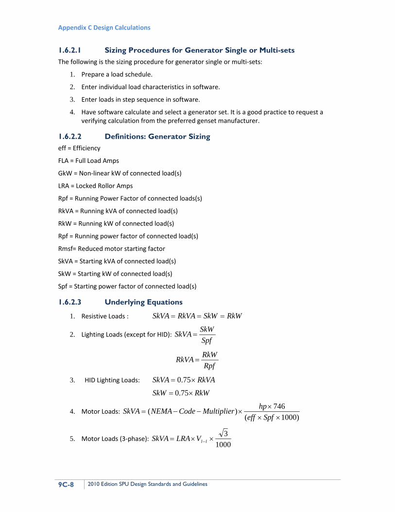
1.6.2.3 Underlying Equations
1. Resistive Loads : RkWSkWRkVASkVA ===
2. Lighting Loads (except for HID): SpfSkWSkVA =
RpfRkWRkVA =
3. HID Lighting Loads: RkVASkVA ×= 75.0
RkWSkW ×= 75.0
4. Motor Loads: )1000(
746)(××
××−−=
SpfeffhpMultiplierCodeNEMASkVA
5. Motor Loads (3-phase): 1000
3××= −llVLRASkVA
AppC_Ch9-DesignClac_8.9.10 Chapter 9 Electrical Design
2010 Edition SPU Design Standards and Guidelines 9C-9
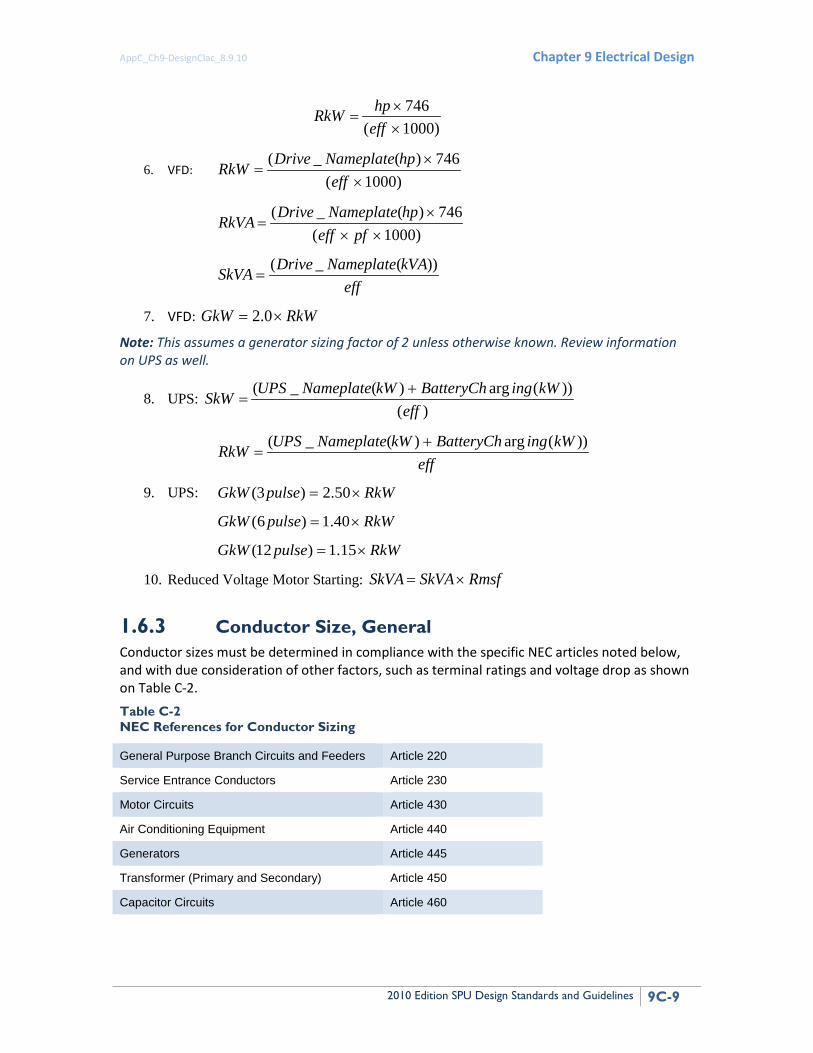
)1000(746
××
=effhpRkW
6. VFD: )1000(
746)(_(×
×=
effhpNameplateDriveRkW
)1000(746)(_(
×××
=pfeff
hpNameplateDriveRkVA
effkVANameplateDriveSkVA ))(_(
=
7. VFD: RkWGkW ×= 0.2
Note: This assumes a generator sizing factor of 2 unless otherwise known. Review information on UPS as well.
8. UPS: )(
))(arg)(_(eff
kWingBatteryChkWNameplateUPSSkW +=
effkWingBatteryChkWNameplateUPSRkW ))(arg)(_( +
=
9. UPS: RkWpulseGkW ×= 50.2)3(
RkWpulseGkW ×= 40.1)6(
RkWpulseGkW ×= 15.1)12(
10. Reduced Voltage Motor Starting: RmsfSkVASkVA ×=
1.6.3 Conductor Size, General Conductor sizes must be determined in compliance with the specific NEC articles noted below, and with due consideration of other factors, such as terminal ratings and voltage drop as shown on Table C-2. Table C-2 NEC References for Conductor Sizing
General Purpose Branch Circuits and Feeders Article 220
Service Entrance Conductors Article 230
Motor Circuits Article 430
Air Conditioning Equipment Article 440
Generators Article 445
Transformer (Primary and Secondary) Article 450
Capacitor Circuits Article 460
Appendix C Design Calculations
9C-10 2010 Edition SPU Design Standards and Guidelines
In this section, we will look at the general requirements for sizing conductors once the calculated load current is known. This is a two-step process:
1. The first step is to look at the temperature rating of the terminals and the ampacity of the conductor that could be used at a matching temperature rating.
2. The second step is to look at the effect of ambient temperature and conductor derating factors on the ampacity of the conductor that results from where and how the conductors are installed.
Insulation used to cover electrical wiring conductors is rated for the maximum temperature it can withstand on a continuous basis. Standard ratings are 60°, 75°, 90°, and 105°C. The current-carrying capability of a conductor is a function of:
• Cross-section of the conductor
• Insulation temperature rating
• Ambient temperature.
The ampacity of a conductor of any size is increased as the rating of its insulation is increased. As the ambient temperature is increased, the ampacity of the conductor must be derated from its ampacity at 30°C. A No. 6 copper conductor with 90°C insulation will be rated for a higher continuous current than a No. 6 copper conductor with 60°C insulation. Because the Underwriters Laboratories, Inc. (UL) places certain restrictions on the size and temperature rating of conductor that can be used at its terminals, conductor size needs to be carefully determined.
The UL tests for switchboards, panelboard, motor starters, and other equipment are made with wiring terminated on the equipment. The equipment is designed to take into account the heat transfer provided by these load-side conductors. If the conductor connected to a circuit breaker is smaller than the tested configuration, it will conduct less heat away from the circuit breaker. This will cause its thermal elements to operate at a lower temperature than with a larger conductor, even though the smaller conductor may be adequate based on the NEC tables for wire size at its insulation rating. For this reason, the UL listing for circuit breakers, and many other types of equipment, is based on standard-size conductors. These standard sizes, in turn, are based on the NEC ampacity for a particular insulation temperature rating. UL uses the following basic rule for circuit breakers:
• Circuit breakers through 125A: Use 60°C insulation ampacity
• Circuits breakers 150A and above: Use 75°C insulation ampacity
Higher rated insulations may be used, but the conductors must be sized based on the lower rated insulation. Of course, these are minimums, and larger wire may be used. Although this is the basic rule, there are exceptions. Equipment where all terminations are rated for use with 75°C wire has become widely available, and this is what we typically ask for in our specifications for all electrical equipment down through 120V panelboards. However, this is not universal, and we must make sure that our wiring is sized appropriately. If you size all smaller circuits (through 125A) based on 60°C wire, you will stay out of trouble.
Paragraphs 210-19 and 215-2 of the NEC require that branch circuit and feeder conductors have an ampacity not less than the load to be served. NEC Paragraph 210-22 contains additional information relative to branch circuit loads. Once branch circuit and feeder loads have been
AppC_Ch9-DesignClac_8.9.10 Chapter 9 Electrical Design
2010 Edition SPU Design Standards and Guidelines 9C-11
determined using applicable sections of NEC Article 230 and other applicable articles, conductor sizes should then be determined using Tables 310-16 through 310-31 of the NEC. The four examples presented below are based on the ampacities presented in NEC Table 310-16, as modified by the applicable correction factors for temperature and conduit fill.
Example 2 Conductor Size No. 1 Conditions: Continuous load rated 43A served by a conduit containing only the conductors for the load, running through a wet area that could have an ambient temperature as high as 42°C. Conductors are to be copper with type THHN/THWN insulation.
Required ampacity per NEC paragraphs 210-16 and 210-22:
• Ampacity required = continuous load x 125% or 53.75 amps
A No. 6 AWG copper conductor having an ampacity of 55 amps (with 60°C insulation) would be the correct choice at the terminals of the circuit breaker serving the load. Note, however, that NEC Table 310-16 applies only up to a maximum ambient temperature of 30°C.
Where the ambient temperature exceeds the 30°C ambient temperature on which Table 310-16 is based, the allowable ampacity of the conductor must be corrected using the correction factors at the bottom of Table 310-16, as required by NEC paragraph 310-10.
• Ampacity of No. 6 conductor (THHN/THWN wet, 75°C column) = 65 amps
• Corrected ampacity = 65 x correction factor (.82) = 65 x .82 = 53.3 amps
Because 53.75 amps is required, this conductor is not adequate. The next larger size conductor will need to be used even though its ampacity was sufficient at the circuit breaker.
If the circuit were being installed where the conductors would never be wet or where conductors with insulation suitable for wet application at 90°C were being used, the 90°C column ampacity of the conductor could be used for determining the corrected ampacity of the conductor in the conduit.
• Ampacity of No. 6 conductor (THHN/THWN DRY, or THWN-2 or XHHW-2 wet, 90°C column) = 75 amps
• Corrected ampacity = 75 x correction factor (.87) = 75 x .87 = 65.2 amps
The No. 6 conductor would be adequate for this installation and could be protected by a 60-amp circuit breaker even though its 60°C rating is only 55 amps. The 60-amp circuit breaker would be allowed by paragraph 240-3, which allows a conductor to be protected by the next larger size overcurrent device if the size of the device is 800 amps or less.
Appendix C Design Calculations
9C-12 2010 Edition SPU Design Standards and Guidelines
Example 3 Conductor Size No. 2 Conditions: The same load and ambient conditions as above, but with 6-phase conductors in the same conduit. We already know that the No. 6 conductors are adequate at the terminals and that they would not be adequate if the circuit were wet—unless the conductor insulation were rated 90°C, wet. Assume the conductors to be No. 6 THWN-2 insulation.
• Corrected ampacity = 75 x correction factor (.87) = 75 x .87 = 65.2 amps
• (Ampacity from 90°C column, corrected for temperature)
Where more than three current-carrying conductors are contained in the same raceway, the ampacity of the conductors must also be derated by the ampacity adjustment factor contained in Note 8 of NEC Tables 310-16 through 310-19.
• Corrected ampacity of six No. 6 conductors = 65.2 x .8 = 52.2 amps
Because 53.75 amps is required, this conductor is not adequate and the next larger size conductor will need to be used, even though its ampacity was sufficient at the circuit breaker.
If the ambient temperature were reduced to below 40°C, the temperature correction factor would be increased to .91, resulting in an increase in the conductor ampacity.
• Corrected ampacity = 75 x .91 (temp. correction) x .8 (six conductors) = 54.6 amps
Again, the No. 6 THWN-2 conductor would be adequate for this installation and could be protected by a 60-amp circuit breaker even though its 60°C rating is only 55 amps.
Example 4 Conductor Size No. 3 Conditions: A feeder with 200A of noncontinuous load and 65A of continuous load to be installed in conduit in a wet area with an ambient temperature of 30°C or less.
• Required ampacity per NEC paragraph 220-10 = noncontinuous load + 1.25 x continuous load
• Or 200 + 1.25 x 65 = 281.25 amps
The feeder overcurrent device would be sized at 300A because that is the next larger standard rating (see Article 240 of the NEC).
The conductor ampacity requirement can be met by either one 300-kCM conductor or two 1/0 conductors with THHN/THWN or XHHW insulation per phase.
AppC_Ch9-DesignClac_8.9.10 Chapter 9 Electrical Design
2010 Edition SPU Design Standards and Guidelines 9C-13
Example 5 Conductor Size No. 3 Conditions: The same load as used in example No. 3, but the conduit is to be installed in a dry area with an ambient temperature of 38°C.
• Required ampacity calculated above = 281.25 amps.
• Ampacity of one 300-kCM THHN/THWN or XHHW conductor is 320 amps in a dry location.
• Correction factor for 90°C conductors in a 38°C ambient temperature = 0.91.
• Corrected ampacity = 320 amps x 0.91 = 291.
If the conductors were being installed in a wet location, the ampacity from the 75°C column would have to be used (refer to Table 310-13 for operating temperature), and the results would be different—unless conductors with insulation rated 90°C, wet, such as THWN-2 or XHHW-2, are used. Note that, at the terminals, the ampacity of the conductors must be based on the temperature rating of the terminals (either 60°C or 75°C); therefore, if the terminals are in a high-ambient-temperature area, this procedure must be modified.
1.6.4 Conduit Size and Fill Where conductors are installed in conduit, the conduit should be sized in accordance with Tables 1 through 5A in Chapter 9 and Appendix C of the NEC, and all associated notes. Following are two examples of how conduits can be sized under different circumstances.
Example 6 Conduit Size and Fill No. 1 Conditions: Three 4/0 AWG conductors with XHHW insulation installed in rigid steel conduit (no separate ground conductor).
See NEC Table C8 for conduit size required for three 4/0 AWG conductors with XHHW insulation.
The table would allow only two conductors to be installed in a 1-1/2-inch conduit and four to be installed in a 2-inch conduit; therefore, a 2-inch conduit is the correct choice.
Appendix C Design Calculations
9C-14 2010 Edition SPU Design Standards and Guidelines
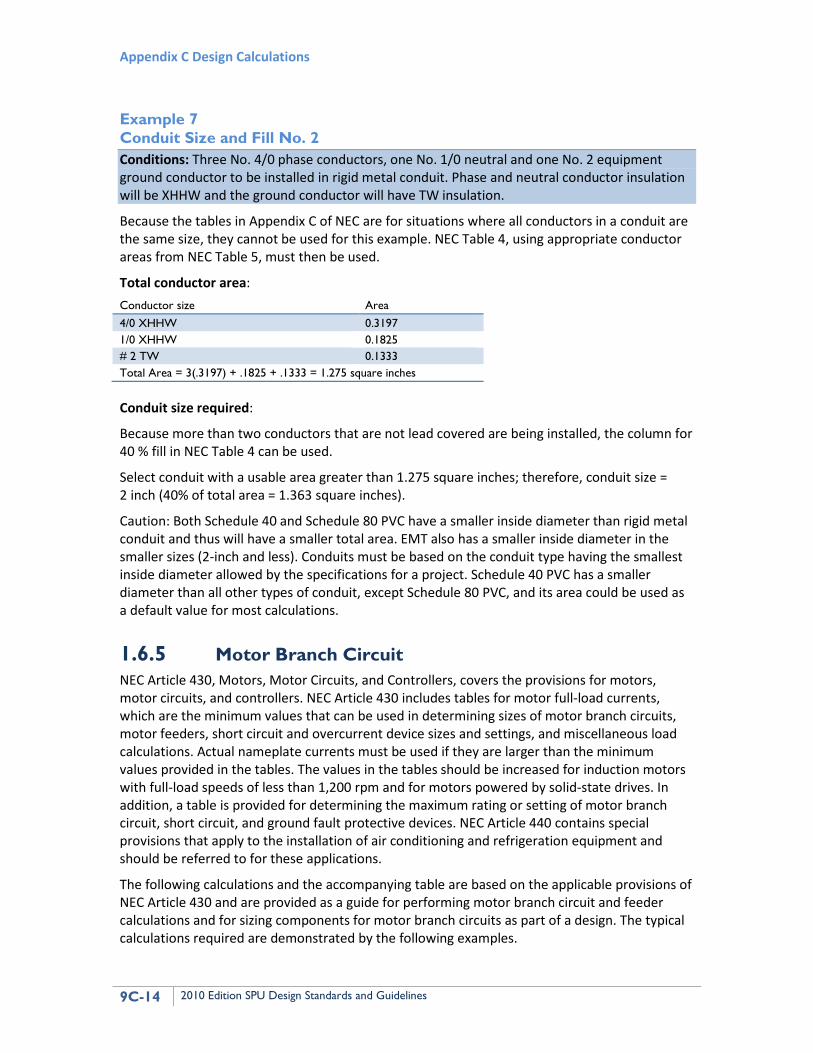
Example 7 Conduit Size and Fill No. 2 Conditions: Three No. 4/0 phase conductors, one No. 1/0 neutral and one No. 2 equipment ground conductor to be installed in rigid metal conduit. Phase and neutral conductor insulation will be XHHW and the ground conductor will have TW insulation.
Because the tables in Appendix C of NEC are for situations where all conductors in a conduit are the same size, they cannot be used for this example. NEC Table 4, using appropriate conductor areas from NEC Table 5, must then be used.
Total conductor area: Conductor size Area 4/0 XHHW 0.3197 1/0 XHHW 0.1825 # 2 TW 0.1333 Total Area = 3(.3197) + .1825 + .1333 = 1.275 square inches Conduit size required:
Because more than two conductors that are not lead covered are being installed, the column for 40 % fill in NEC Table 4 can be used.
Select conduit with a usable area greater than 1.275 square inches; therefore, conduit size = 2 inch (40% of total area = 1.363 square inches).
Caution: Both Schedule 40 and Schedule 80 PVC have a smaller inside diameter than rigid metal conduit and thus will have a smaller total area. EMT also has a smaller inside diameter in the smaller sizes (2-inch and less). Conduits must be based on the conduit type having the smallest inside diameter allowed by the specifications for a project. Schedule 40 PVC has a smaller diameter than all other types of conduit, except Schedule 80 PVC, and its area could be used as a default value for most calculations.
1.6.5 Motor Branch Circuit NEC Article 430, Motors, Motor Circuits, and Controllers, covers the provisions for motors, motor circuits, and controllers. NEC Article 430 includes tables for motor full-load currents, which are the minimum values that can be used in determining sizes of motor branch circuits, motor feeders, short circuit and overcurrent device sizes and settings, and miscellaneous load calculations. Actual nameplate currents must be used if they are larger than the minimum values provided in the tables. The values in the tables should be increased for induction motors with full-load speeds of less than 1,200 rpm and for motors powered by solid-state drives. In addition, a table is provided for determining the maximum rating or setting of motor branch circuit, short circuit, and ground fault protective devices. NEC Article 440 contains special provisions that apply to the installation of air conditioning and refrigeration equipment and should be referred to for these applications.
The following calculations and the accompanying table are based on the applicable provisions of NEC Article 430 and are provided as a guide for performing motor branch circuit and feeder calculations and for sizing components for motor branch circuits as part of a design. The typical calculations required are demonstrated by the following examples.
AppC_Ch9-DesignClac_8.9.10 Chapter 9 Electrical Design
2010 Edition SPU Design Standards and Guidelines 9C-15
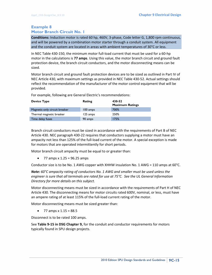
Example 8 Motor Branch Circuit No. 1 Conditions: Induction motor is rated 60 hp, 460V, 3-phase, Code letter G, 1,800 rpm continuous, and will be powered by a combination motor starter through a conduit system. All equipment and the conduit system are located in areas with ambient temperatures of 30°C or less.
In NEC Table 430-150, the minimum motor full-load current that must be used for a 60-hp motor in the calculations is 77 amps. Using this value, the motor branch circuit and ground fault protection device, the branch circuit conductors, and the motor disconnecting means can be sized.
Motor branch circuit and ground fault protection devices are to be sized as outlined in Part IV of NEC Article 430, with maximum settings as provided in NEC Table 430-52. Actual settings should reflect the recommendation of the manufacturer of the motor control equipment that will be provided.
For example, following are General Electric's recommendations:
Device Type Rating 430-52 Maximum Ratings
Magnetic-only circuit breaker 100 amps 700% Thermal magnetic breaker 125 amps 250% Time delay fuses 90 amps 175%
Branch circuit conductors must be sized in accordance with the requirements of Part B of NEC Article 430. NEC paragraph 430-22 requires that conductors supplying a motor must have an ampacity not less than 125% of the full-load current of the motor. A special exception is made for motors that are operated intermittently for short periods.
Motor branch circuit ampacity must be equal to or greater than:
• 77 amps x 1.25 = 96.25 amps
Conductor size is to be No. 1 AWG copper with XHHW insulation No. 1 AWG = 110 amps at 60°C.
Note: 60°C ampacity rating of conductors No. 1 AWG and smaller must be used unless the engineer is sure that all terminals are rated for use at 75°C. See the UL General Information Directory for more details on this subject.
Motor disconnecting means must be sized in accordance with the requirements of Part H of NEC Article 430. The disconnecting means for motor circuits rated 600V, nominal, or less, must have an ampere rating of at least 115% of the full-load current rating of the motor.
Motor disconnecting means must be sized greater than:
• 77 amps x 1.15 = 88.5
Disconnect is to be rated 100 amps.
See Table 9-15 in DSG Chapter 9, for the conduit and conductor requirements for motors typically found in SPU design projects.
Appendix C Design Calculations
9C-16 2010 Edition SPU Design Standards and Guidelines
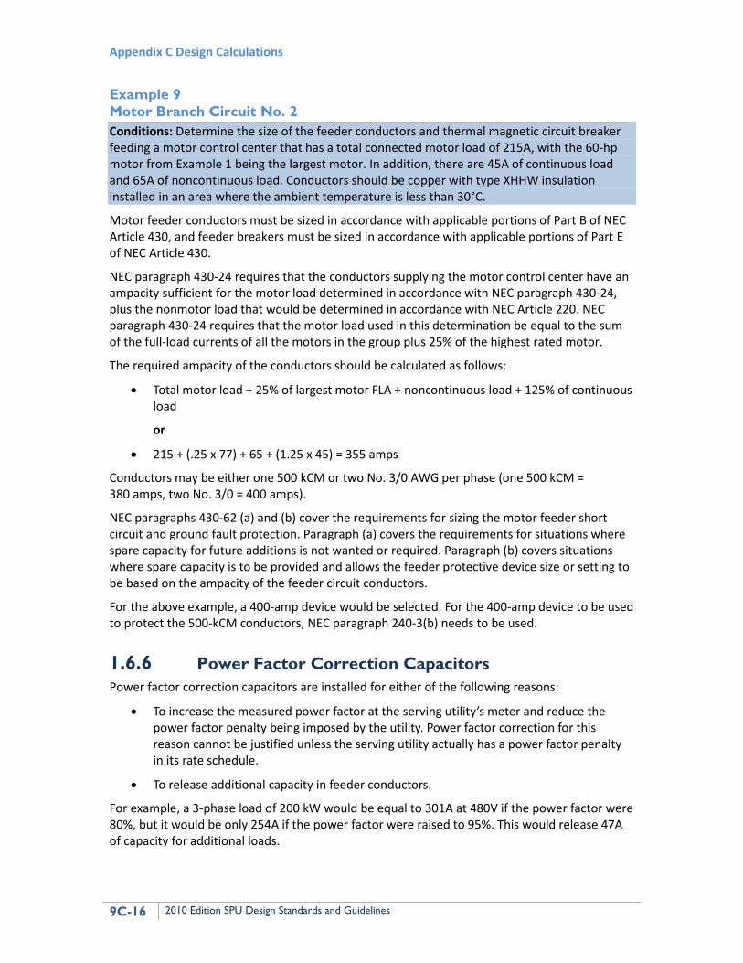
Example 9 Motor Branch Circuit No. 2 Conditions: Determine the size of the feeder conductors and thermal magnetic circuit breaker feeding a motor control center that has a total connected motor load of 215A, with the 60-hp motor from Example 1 being the largest motor. In addition, there are 45A of continuous load and 65A of noncontinuous load. Conductors should be copper with type XHHW insulation installed in an area where the ambient temperature is less than 30°C.
Motor feeder conductors must be sized in accordance with applicable portions of Part B of NEC Article 430, and feeder breakers must be sized in accordance with applicable portions of Part E of NEC Article 430.
NEC paragraph 430-24 requires that the conductors supplying the motor control center have an ampacity sufficient for the motor load determined in accordance with NEC paragraph 430-24, plus the nonmotor load that would be determined in accordance with NEC Article 220. NEC paragraph 430-24 requires that the motor load used in this determination be equal to the sum of the full-load currents of all the motors in the group plus 25% of the highest rated motor.
The required ampacity of the conductors should be calculated as follows:
• Total motor load + 25% of largest motor FLA + noncontinuous load + 125% of continuous load
or
• 215 + (.25 x 77) + 65 + (1.25 x 45) = 355 amps
Conductors may be either one 500 kCM or two No. 3/0 AWG per phase (one 500 kCM = 380 amps, two No. 3/0 = 400 amps).
NEC paragraphs 430-62 (a) and (b) cover the requirements for sizing the motor feeder short circuit and ground fault protection. Paragraph (a) covers the requirements for situations where spare capacity for future additions is not wanted or required. Paragraph (b) covers situations where spare capacity is to be provided and allows the feeder protective device size or setting to be based on the ampacity of the feeder circuit conductors.
For the above example, a 400-amp device would be selected. For the 400-amp device to be used to protect the 500-kCM conductors, NEC paragraph 240-3(b) needs to be used.
1.6.6 Power Factor Correction Capacitors Power factor correction capacitors are installed for either of the following reasons:
• To increase the measured power factor at the serving utility’s meter and reduce the power factor penalty being imposed by the utility. Power factor correction for this reason cannot be justified unless the serving utility actually has a power factor penalty in its rate schedule.
• To release additional capacity in feeder conductors.
For example, a 3-phase load of 200 kW would be equal to 301A at 480V if the power factor were 80%, but it would be only 254A if the power factor were raised to 95%. This would release 47A of capacity for additional loads.
AppC_Ch9-DesignClac_8.9.10 Chapter 9 Electrical Design
2010 Edition SPU Design Standards and Guidelines 9C-17
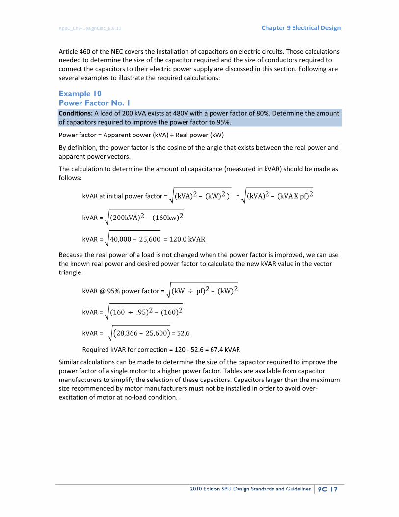
Article 460 of the NEC covers the installation of capacitors on electric circuits. Those calculations needed to determine the size of the capacitor required and the size of conductors required to connect the capacitors to their electric power supply are discussed in this section. Following are several examples to illustrate the required calculations:
Example 10 Power Factor No. 1 Conditions: A load of 200 kVA exists at 480V with a power factor of 80%. Determine the amount of capacitors required to improve the power factor to 95%.
Power factor = Apparent power (kVA) ÷ Real power (kW)
By definition, the power factor is the cosine of the angle that exists between the real power and apparent power vectors.
The calculation to determine the amount of capacitance (measured in kVAR) should be made as follows:
kVAR at initial power factor = �(kVA)2 – (kW)2 ) = �(kVA)2 – (kVA X pf)2
kVAR = �(200kVA)2 – (160kw)2
kVAR = �40,000 – 25,600 = 120.0 kVAR
Because the real power of a load is not changed when the power factor is improved, we can use the known real power and desired power factor to calculate the new kVAR value in the vector triangle:
kVAR @ 95% power factor = �(kW ÷ pf)2 – (kW)2
kVAR = �(160 ÷ .95)2 – (160)2
kVAR = ��28,366 – 25,600� = 52.6
Required kVAR for correction = 120 - 52.6 = 67.4 kVAR
Similar calculations can be made to determine the size of the capacitor required to improve the power factor of a single motor to a higher power factor. Tables are available from capacitor manufacturers to simplify the selection of these capacitors. Capacitors larger than the maximum size recommended by motor manufacturers must not be installed in order to avoid over-excitation of motor at no-load condition.
Appendix C Design Calculations
9C-18 2010 Edition SPU Design Standards and Guidelines
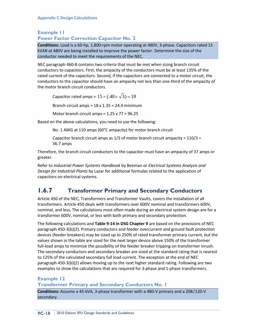
Example 11 Power Factor Correction Capacitor No. 2 Conditions: Load is a 60-hp, 1,800-rpm motor operating at 480V, 3-phase. Capacitors rated 15 kVAR at 480V are being installed to improve the power factor. Determine the size of the conductor needed to meet the requirements of the NEC.
NEC paragraph 460-8 contains two criteria that must be met when sizing branch circuit conductors to capacitors. First, the ampacity of the conductors must be at least 135% of the rated current of the capacitors. Second, if the capacitors are connected to a motor circuit, the conductors to the capacitor should have an ampacity not less than one-third of the ampacity of the motor branch circuit conductors.
Capacitor rated amps = 18)3(.48 15 =×÷
Branch circuit amps = 18 x 1.35 = 24.4 minimum
Motor branch circuit amps = 1.25 x 77 = 96.25
Based on the above calculations, you need to use the following:
No. 1 AWG at 110 amps (60°C ampacity) for motor branch circuit
Capacitor branch circuit amps as 1/3 of motor branch circuit ampacity = 110/3 = 36.7 amps
Therefore, the branch circuit conductors to the capacitor must have an ampacity of 37 amps or greater.
Refer to Industrial Power Systems Handbook by Beeman or Electrical Systems Analysis and Design for Industrial Plants by Lazar for additional formulas related to the application of capacitors on electrical systems.
1.6.7 Transformer Primary and Secondary Conductors Article 450 of the NEC, Transformers and Transformer Vaults, covers the installation of all transformers. Article 450 deals with transformers over 600V nominal and transformers 600V, nominal, and less. The calculations most often made during an electrical system design are for a transformer 600V, nominal, or less with both primary and secondary protection.
The following calculations and Table 9-14 in DSG Chapter 9 are based on the provisions of NEC paragraph 450-3(b)(2). Primary conductors and feeder overcurrent and ground fault protection devices (feeder breakers) may be sized up to 250% of rated transformer primary current, but the values shown in the table are sized for the next larger device above 150% of the transformer full-load amps to minimize the possibility of the feeder breaker tripping on transformer inrush. The secondary conductors and secondary breaker are sized at the standard rating that is nearest to 125% of the calculated secondary full load current. The exception at the end of NEC paragraph 450-3(b)(2) allows moving up to the next higher standard rating. Following are two examples to show the calculations that are required for 3-phase and 1-phase transformers.
Example 12 Transformer Primary and Secondary Conductors No. 1 Conditions: Assume a 45-kVA, 3-phase transformer with a 480-V primary and a 208A/ E A120-V secondary.
AppC_Ch9-DesignClac_8.9.10 Chapter 9 Electrical Design
2010 Edition SPU Design Standards and Guidelines 9C-19
Calculate primary full-load amps:
45 kVA ÷ ((480 volts x 1.73) ÷1000) = 54.2 amps
Calculate required feeder breaker and conductor ampacity:
54.2 amps x 1.5 = 81 amps
Use a 90-amp breaker and No. 3 AWG copper conductors0F
1
Calculate secondary full-load amps:
45 kVA ÷ ((208 volts x 1.73) ÷ 1000) = 125.06 amps
Calculate required secondary breaker size and conductor ampacity at 125% secondary full-load amps:
125.06 amps x 1.25 = 156.3 amps
Use a 150-amp breaker and No. 1/0 copper conductors1
Note: This selection limits the continuous load that can be supplied by the transformer to 43.2 kVA ((80% x 208 volts x 150 amps x 1.73) ÷ 1000).
The ground conductors for the above circuits must be sized in accordance with NEC Tables 250 94 and 250-95. The ground conductor in the feeder to the primary should be sized as an equipment ground in accordance with NEC Table 250-95. The grounding electrode conductor on the secondary of the transformer must be sized as required by NEC paragraph 250-26 using Table 250-94.
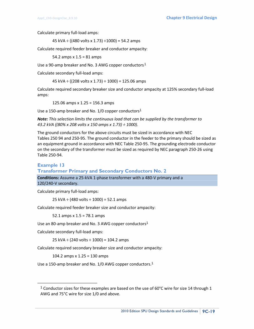
Example 13 Transformer Primary and Secondary Conductors No. 2 Conditions: Assume a 25-kVA 1-phase transformer with a 480-V primary and a 120/240-V secondary.
Calculate primary full-load amps:
25 kVA ÷ (480 volts ÷ 1000) = 52.1 amps
Calculate required feeder breaker size and conductor ampacity:
52.1 amps x 1.5 = 78.1 amps
Use an 80-amp breaker and No. 3 AWG copper conductors1
Calculate secondary full-load amps:
25 kVA ÷ (240 volts ÷ 1000) = 104.2 amps
Calculate required secondary breaker size and conductor ampacity:
104.2 amps x 1.25 = 130 amps
Use a 150-amp breaker and No. 1/0 AWG copper conductors.1
1 Conductor sizes for these examples are based on the use of 60°C wire for size 14 through 1 AWG and 75°C wire for size 1/0 and above.
Appendix C Design Calculations
9C-20 2010 Edition SPU Design Standards and Guidelines
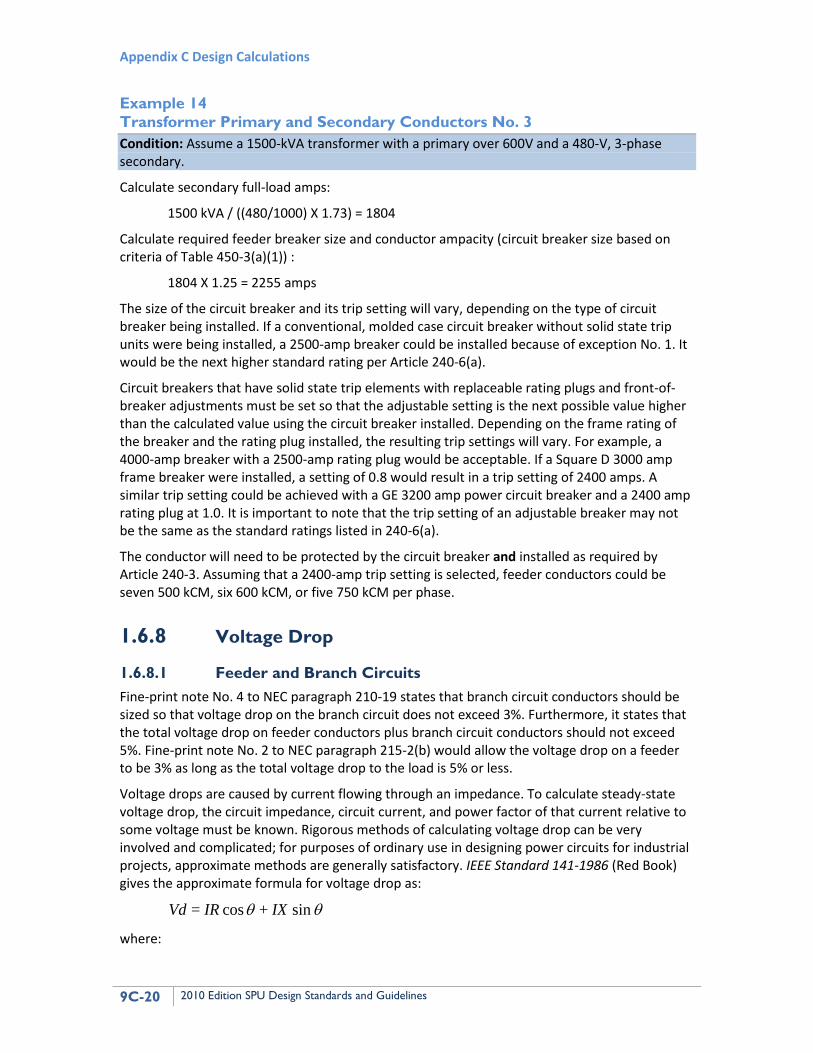
Example 14 Transformer Primary and Secondary Conductors No. 3 Condition: Assume a 1500-kVA transformer with a primary over 600V and a 480-V, 3-phase secondary.
Calculate secondary full-load amps:
1500 kVA / ((480/1000) X 1.73) = 1804
Calculate required feeder breaker size and conductor ampacity (circuit breaker size based on criteria of Table 450-3(a)(1)) :
1804 X 1.25 = 2255 amps
The size of the circuit breaker and its trip setting will vary, depending on the type of circuit breaker being installed. If a conventional, molded case circuit breaker without solid state trip units were being installed, a 2500-amp breaker could be installed because of exception No. 1. It would be the next higher standard rating per Article 240-6(a).
Circuit breakers that have solid state trip elements with replaceable rating plugs and front-of-breaker adjustments must be set so that the adjustable setting is the next possible value higher than the calculated value using the circuit breaker installed. Depending on the frame rating of the breaker and the rating plug installed, the resulting trip settings will vary. For example, a 4000-amp breaker with a 2500-amp rating plug would be acceptable. If a Square D 3000 amp frame breaker were installed, a setting of 0.8 would result in a trip setting of 2400 amps. A similar trip setting could be achieved with a GE 3200 amp power circuit breaker and a 2400 amp rating plug at 1.0. It is important to note that the trip setting of an adjustable breaker may not be the same as the standard ratings listed in 240-6(a).
The conductor will need to be protected by the circuit breaker and installed as required by Article 240-3. Assuming that a 2400-amp trip setting is selected, feeder conductors could be seven 500 kCM, six 600 kCM, or five 750 kCM per phase.
1.6.8 Voltage Drop
1.6.8.1 Feeder and Branch Circuits Fine-print note No. 4 to NEC paragraph 210-19 states that branch circuit conductors should be sized so that voltage drop on the branch circuit does not exceed 3%. Furthermore, it states that the total voltage drop on feeder conductors plus branch circuit conductors should not exceed 5%. Fine-print note No. 2 to NEC paragraph 215-2(b) would allow the voltage drop on a feeder to be 3% as long as the total voltage drop to the load is 5% or less.
Voltage drops are caused by current flowing through an impedance. To calculate steady-state voltage drop, the circuit impedance, circuit current, and power factor of that current relative to some voltage must be known. Rigorous methods of calculating voltage drop can be very involved and complicated; for purposes of ordinary use in designing power circuits for industrial projects, approximate methods are generally satisfactory. IEEE Standard 141-1986 (Red Book) gives the approximate formula for voltage drop as:
θθ sin + cos = IXIRVd
where:
AppC_Ch9-DesignClac_8.9.10 Chapter 9 Electrical Design
2010 Edition SPU Design Standards and Guidelines 9C-21
Vd = voltage drop in circuit, line to neutral
I = current flowing in conductor
R = line resistance for one conductor in ohms
X = line reactance for one conductor in ohms
θ= angle whose cosine is the load power factor
cosθ = load real power factor
sin θ= load reactive power factor
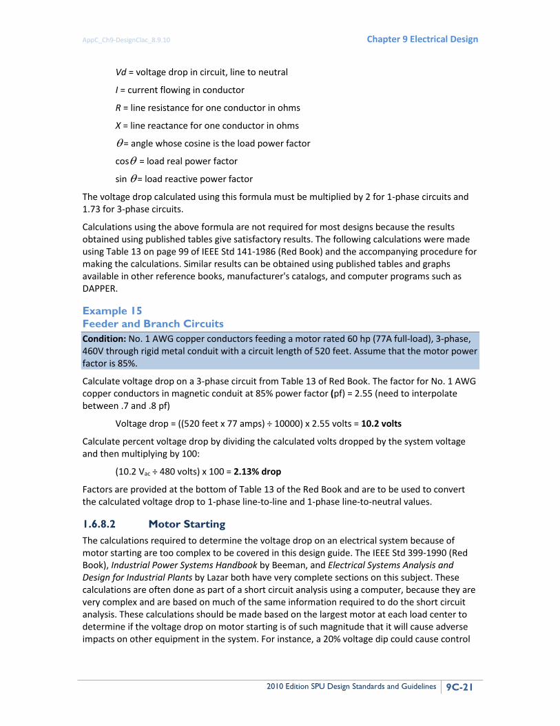
The voltage drop calculated using this formula must be multiplied by 2 for 1-phase circuits and 1.73 for 3-phase circuits.
Calculations using the above formula are not required for most designs because the results obtained using published tables give satisfactory results. The following calculations were made using Table 13 on page 99 of IEEE Std 141-1986 (Red Book) and the accompanying procedure for making the calculations. Similar results can be obtained using published tables and graphs available in other reference books, manufacturer's catalogs, and computer programs such as DAPPER.
Example 15 Feeder and Branch Circuits Condition: No. 1 AWG copper conductors feeding a motor rated 60 hp (77A full-load), 3-phase, 460V through rigid metal conduit with a circuit length of 520 feet. Assume that the motor power factor is 85%.
Calculate voltage drop on a 3-phase circuit from Table 13 of Red Book. The factor for No. 1 AWG copper conductors in magnetic conduit at 85% power factor (pf) = 2.55 (need to interpolate between .7 and .8 pf)
Voltage drop = ((520 feet x 77 amps) ÷ 10000) x 2.55 volts = 10.2 volts
Calculate percent voltage drop by dividing the calculated volts dropped by the system voltage and then multiplying by 100:
(10.2 Vac ÷ 480 volts) x 100 = 2.13% drop
Factors are provided at the bottom of Table 13 of the Red Book and are to be used to convert the calculated voltage drop to 1-phase line-to-line and 1-phase line-to-neutral values.
1.6.8.2 Motor Starting The calculations required to determine the voltage drop on an electrical system because of motor starting are too complex to be covered in this design guide. The IEEE Std 399-1990 (Red Book), Industrial Power Systems Handbook by Beeman, and Electrical Systems Analysis and Design for Industrial Plants by Lazar both have very complete sections on this subject. These calculations are often done as part of a short circuit analysis using a computer, because they are very complex and are based on much of the same information required to do the short circuit analysis. These calculations should be made based on the largest motor at each load center to determine if the voltage drop on motor starting is of such magnitude that it will cause adverse impacts on other equipment in the system. For instance, a 20% voltage dip could cause control
Appendix C Design Calculations
9C-22 2010 Edition SPU Design Standards and Guidelines
relays to drop out, since many of these are designed to operate only at voltage levels 15% below rated voltage.
1.6.9 Short Circuit The proper selection of protective devices and coordination of their trip settings is based on short circuit calculations. The calculations required to complete a detailed short circuit analysis are very complex and beyond the scope of this design guide. The Industrial Power Systems Handbook by Beeman, Electrical Systems Analysis and Design for Industrial Plants by Lazar, the IEEE Std 399-1990, and many other references contain detailed procedures for performing short circuit analysis.
In those situations where an approximate value of short circuit current is needed for preliminary design purposes, the following abbreviated method can be used to estimate a very conservative value of maximum fault current. This result will exceed the actual fault current, since many small impedances are neglected to simplify the calculations. In every situation where this method is used, a detailed calculation, either made by hand or using an approved computer program, should be made during final design.
Calculations to determine an approximate value of symmetrical short circuit current in a power distribution system are shown in the following example.
Example 16 Short Circuit Conditions: The load will be served by a 1,500-kVA transformer at 480V 3-phase through a single motor control center. The fault current available from the utility on the source side of the transformer is unknown, the transformer impedance is assumed to be 5.75% (based on published data), and the motor load on the transformer is approximately 75% of the rating of the transformer. Note that the standard transformer impedance is valued at +/- 7.5% of nominal. Therefore for a conservative calculation the lowest impedance should be used:
5.75% x ((100%-7.5%) ÷100) = 5.32%
The current flowing during a fault at any point in an electrical system is limited by the impedance of the circuits and equipment from the source or sources to the point where the fault has occurred. For these simplified calculations, we will assume that the only sources are the transformer and the motors connected to the system. The motors are connected in parallel with the transformer as an impedance with an infinite bus as the source of the fault current.
The basic formula used to calculate short circuit currents is:
Short circuit current = Driving Voltage/ Total Impedance (Ohm's law)
A point-to-point calculation of short circuit current available at any point can be made using this formula. It is the basic formula used in the per-unit method to calculate short circuit current values in electric power circuits. The reactance of the utility system must be assumed zero, and the following simplification can be made to determine short circuit current let through by a transformer:
Approximate transformer per-unit Z = (%Z)(base kVA) ÷ ((100) (transformer kVA))
If we let base kVA = transformer kVA, then:
AppC_Ch9-DesignClac_8.9.10 Chapter 9 Electrical Design
2010 Edition SPU Design Standards and Guidelines 9C-23
per-unit Z of the transformer = %Z / 100
The basic formula for calculating short circuit current when the per-unit method is used is:
Is.c. rms sym = base kVA ÷ (1.73 x kV x (per-unit Z of the transformer)
Because we have let base kVA = transformer kVA and transformer kVA ÷ (1.73 x kV) = transformer load current for three phase transformers, we can simplify the above formula to:
Is.c. rms sym = transformer FLA ÷ (%Z ÷ 100)
transformer FLA = 1,500 kVA ÷ (.48 x 1.73) or FLA = 1,806.4 amps
The resulting short circuit current let through by the transformer in our example would be:
Is.c.rms sym = 1806.4 ÷ (5.32 ÷ 100)
or
Is.c. rms sym = 33,955 amps
The motor contribution to a fault by a single or group of low-voltage induction motors can be taken as approximately five times the motor full-load current. This is because the reactance of a low-voltage induction motor, including the leads, is approximately 20%. A point-to-point calculation made as above for a transformer would result in a multiplier of 5.
Motor load of 75% of transformer rating was given; therefore, motor FLA would be 1,806 x .75 = 1,355 amps.
Is.c. rms sym = 1,355 x 5 = 6775 amps
The total short circuit current available at the point of the fault would be the total of the contribution from the transformer plus the contribution for the motor load or
total Is.c. rms sym = 33,955 + 6775
or
40,730 amps rms sym
Because neither the serving utility’s source impedance nor the impedances of the interconnecting conductors and equipment are included in this calculation, this value can be very conservative and must be used carefully.
1.6.10 Lighting Lighting calculations shall be made using the recommended procedures established by the Illuminating Engineering Society and outlined in the IES Lighting Handbook. Two methods are available for calculating the lighting levels in a space: the lumen or zonal cavity method and the point-by-point method. The zonal cavity method is used to calculate the average foot-candle level within the space, and the point-by-point method is used to predict the illumination for a specific visual task. The following examples are provided to demonstrate these two calculation methods.
Appendix C Design Calculations
9C-24 2010 Edition SPU Design Standards and Guidelines
Example 17 Lighting No 1: Lumen or Zonal Cavity Method Conditions: Design a lighting system for a room 15 feet x 25 feet, with an 11-foot ceiling that will be used for general office work. The ceiling will be lay-in ceiling tile and the walls will be painted off-white. The luminaires will be cleaned regularly and lamps will be group-replaced when the first failures start to occur.
Basic equations:
Footcandles Total Lumens Striking AreaArea
=
AreaLLFCUlamplumenslampssFootcandle ×××
=)/(
where:
CU = coefficient of utilization
LLF = light loss factor
LLF is made up of a number of factors. The ones to be included in most calculations are lamp lumen depreciation (LLD), luminaire dirt depreciation (LDD), and room surface depreciation (RSD).
The CU of a luminaire is calculated by the zonal cavity method and is a measure of how a specific luminaire distributes light into a given room. The CU takes into account luminaire efficiency, candle-power distribution of the luminaire, room size and shape, mounting height, and surface reflectances. The CU for a specific luminaire must be obtained from the manufacturer's catalog.
To determine the CU for a specific application, several values must be determined:
• Effective floor cavity reflectance
• Effective ceiling cavity reflectance
• Wall reflectance
• Room cavity ratio (RCR)
Most CU tables are based on a floor cavity ratio (PFC) of 20, so that figure will be used for this example.
If the suspension length of the luminaire below the ceiling is zero, which it is for this example, the ceiling cavity ratio (PCC) is equal to the ceiling reflectance. If the luminaire is suspended, a ceiling cavity ratio must be calculated before the effective ceiling cavity reflectance can be determined. Reflectance values for various surfaces are available in the IES Lighting Handbook. For this example, 70% will be used.
The wall reflectance (PW) of materials can be obtained from the IES Lighting Handbook. For this example, 70% will be used.
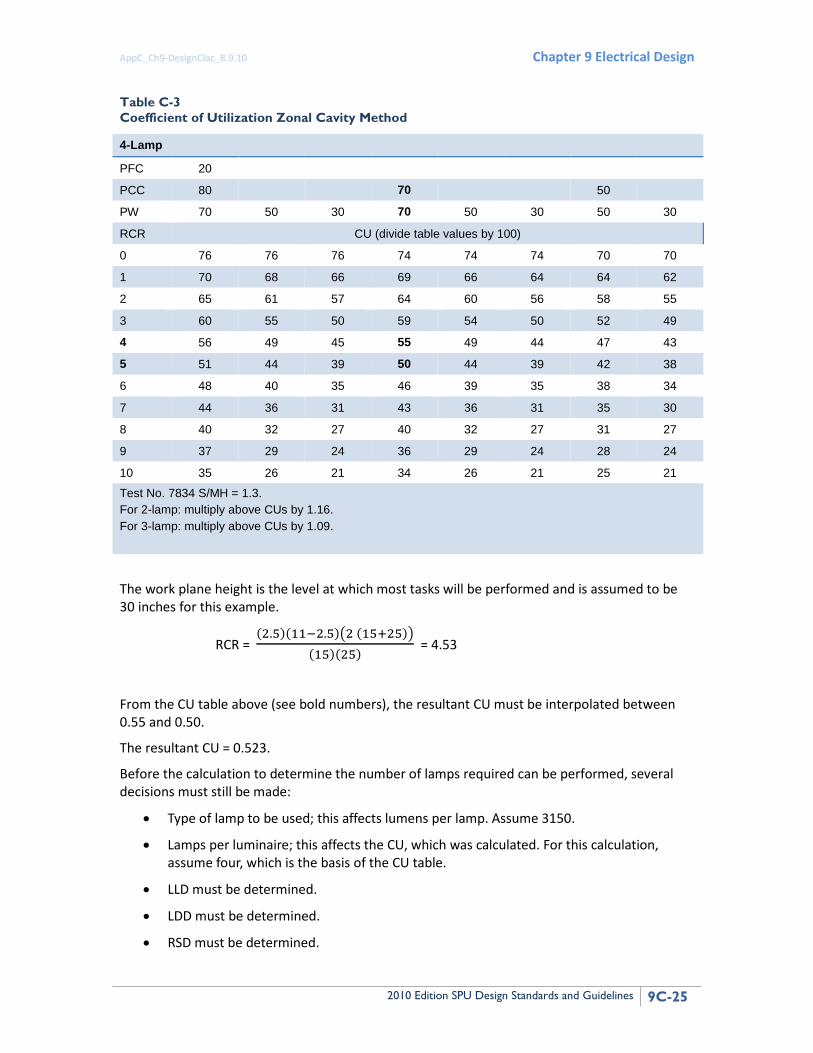
The RCR must be calculated; it is equal to 2.5 times the area of the walls divided by the area of the work plane (Table C-3):
AppC_Ch9-DesignClac_8.9.10 Chapter 9 Electrical Design
2010 Edition SPU Design Standards and Guidelines 9C-25
Table C-3 Coefficient of Utilization Zonal Cavity Method
4-Lamp
PFC 20
PCC 80 70 50
PW 70 50 30 70 50 30 50 30
RCR CU (divide table values by 100)
0 76 76 76 74 74 74 70 70
1 70 68 66 69 66 64 64 62
2 65 61 57 64 60 56 58 55
3 60 55 50 59 54 50 52 49
4 56 49 45 55 49 44 47 43
5 51 44 39 50 44 39 42 38
6 48 40 35 46 39 35 38 34
7 44 36 31 43 36 31 35 30
8 40 32 27 40 32 27 31 27
9 37 29 24 36 29 24 28 24
10 35 26 21 34 26 21 25 21
Test No. 7834 S/MH = 1.3. For 2-lamp: multiply above CUs by 1.16. For 3-lamp: multiply above CUs by 1.09.
The work plane height is the level at which most tasks will be performed and is assumed to be 30 inches for this example.
RCR = (2.5)(11−2.5)�2 (15+25)�
(15)(25) = 4.53
From the CU table above (see bold numbers), the resultant CU must be interpolated between 0.55 and 0.50.
The resultant CU = 0.523.
Before the calculation to determine the number of lamps required can be performed, several decisions must still be made:
• Type of lamp to be used; this affects lumens per lamp. Assume 3150.
• Lamps per luminaire; this affects the CU, which was calculated. For this calculation, assume four, which is the basis of the CU table.
• LLD must be determined.
• LDD must be determined.
• RSD must be determined.
Appendix C Design Calculations
9C-26 2010 Edition SPU Design Standards and Guidelines
• Foot-candle level desired must be determined.
Values for LLD, LDD, RSD, and a number of other factors that cause light loss in the space can be found in the IES Lighting Handbook. For most calculations dealing with lighting in noncritical areas, however, all of these factors can be combined into a single factor, which is often referred to as the light loss factor (LLF). For this calculation, an LLF of 0.75 has been assumed. Foot-candle levels are recommended for a number of applications in the IES Lighting Handbook. The recommended level for general office work falls between 50 and 150 foot-candles, depending on the level of difficulty of the task. For this calculation, the level required is assumed to be 100 foot-candles.
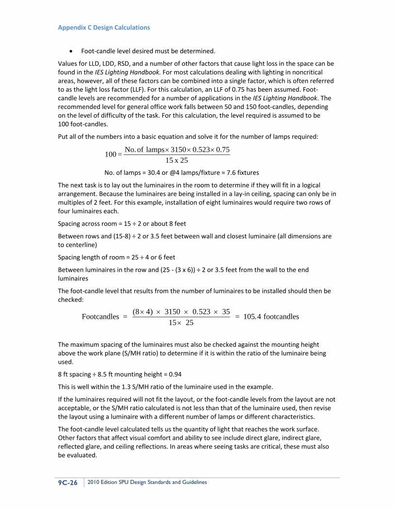
Put all of the numbers into a basic equation and solve it for the number of lamps required:
25 x 15
0.75 0.523 3150 lamps of No. = 100 ×××
No. of lamps = 30.4 or @4 lamps/fixture = 7.6 fixtures
The next task is to lay out the luminaires in the room to determine if they will fit in a logical arrangement. Because the luminaires are being installed in a lay-in ceiling, spacing can only be in multiples of 2 feet. For this example, installation of eight luminaires would require two rows of four luminaires each.
Spacing across room = 15 ÷ 2 or about 8 feet
Between rows and (15-8) ÷ 2 or 3.5 feet between wall and closest luminaire (all dimensions are to centerline)
Spacing length of room = 25 ÷ 4 or 6 feet
Between luminaires in the row and (25 - (3 x 6)) ÷ 2 or 3.5 feet from the wall to the end luminaires
The foot-candle level that results from the number of luminaires to be installed should then be checked:
Footcandles = (8 4) 3150 0.523 3515 25
= 105.4 footcandles
× × × ××
The maximum spacing of the luminaires must also be checked against the mounting height above the work plane (S/MH ratio) to determine if it is within the ratio of the luminaire being used.
8 ft spacing ÷ 8.5 ft mounting height = 0.94
This is well within the 1.3 S/MH ratio of the luminaire used in the example.
If the luminaires required will not fit the layout, or the foot-candle levels from the layout are not acceptable, or the S/MH ratio calculated is not less than that of the luminaire used, then revise the layout using a luminaire with a different number of lamps or different characteristics.
The foot-candle level calculated tells us the quantity of light that reaches the work surface. Other factors that affect visual comfort and ability to see include direct glare, indirect glare, reflected glare, and ceiling reflections. In areas where seeing tasks are critical, these must also be evaluated.
AppC_Ch9-DesignClac_8.9.10 Chapter 9 Electrical Design
2010 Edition SPU Design Standards and Guidelines 9C-27
See the IES Lighting Handbook and other lighting design and application guides for additional information on these subjects.
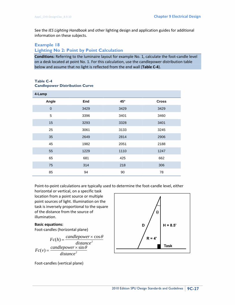
Example 18 Lighting No 2: Point by Point Calculation Conditions: Referring to the luminaire layout for example No. 1, calculate the foot-candle level on a desk located at point No. 1. For this calculation, use the candlepower distribution table below and assume that no light is reflected from the end wall (Table C-4).
Table C-4 Candlepower Distribution Curve
4-Lamp
Angle End 45° Cross
0 3429 3429 3429
5 3396 3401 3460
15 3293 3328 3401
25 3061 3133 3245
35 2649 2814 2906
45 1982 2051 2188
55 1229 1110 1247
65 681 425 662
75 314 218 306
85 94 90 78
Point-to-point calculations are typically used to determine the foot-candle level, either horizontal or vertical, on a specific task location from a point source or multiple point sources of light. Illumination on the task is inversely proportional to the square of the distance from the source of illumination.
Basic equations: Foot-candles (horizontal plane)
Fc h candlepower( ) cos=
× θdistance2
Fc v candlepower( ) sin=
× θdistance2
Foot-candles (vertical plane)
Appendix C Design Calculations
9C-28 2010 Edition SPU Design Standards and Guidelines
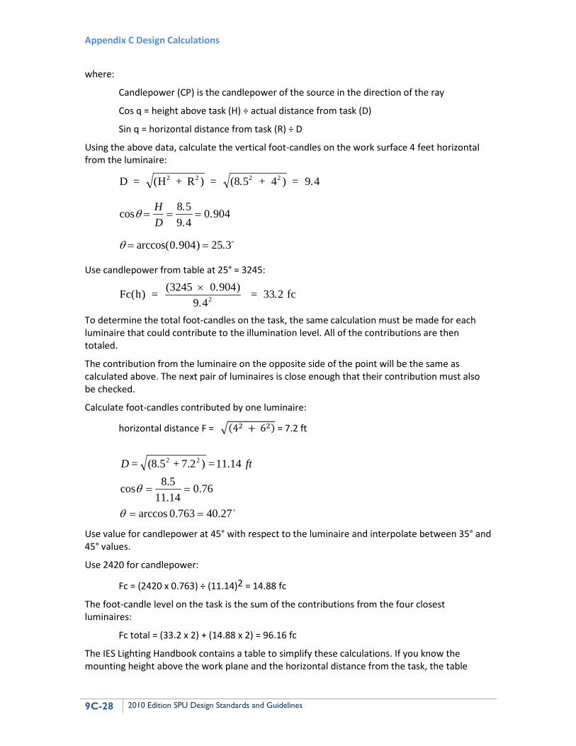
where:
Candlepower (CP) is the candlepower of the source in the direction of the ray
Cos q = height above task (H) ÷ actual distance from task (D)
Sin q = horizontal distance from task (R) ÷ D
Using the above data, calculate the vertical foot-candles on the work surface 4 feet horizontal from the luminaire:
D = (H + R ) = (8.5 + 4 ) = 9.42 2 2 2
cos ..
.
arccos . ) .
θ
θ
= = =
= =
HD
8 59 4
0 904
0 904 25 3(
Use candlepower from table at 25° = 3245:
Fc(h) = (3245 0.904) = 33.2 fc×9 42.
To determine the total foot-candles on the task, the same calculation must be made for each luminaire that could contribute to the illumination level. All of the contributions are then totaled.
The contribution from the luminaire on the opposite side of the point will be the same as calculated above. The next pair of luminaires is close enough that their contribution must also be checked.
Calculate foot-candles contributed by one luminaire:
horizontal distance F = �(42 + 62) = 7.2 ft
27.40763.0 arccos
76.014.115.8cos
14.11 = )2.7 + 5.8( = 22
==
==
θ
θ
ftD
Use value for candlepower at 45° with respect to the luminaire and interpolate between 35° and 45° values.
Use 2420 for candlepower:
Fc = (2420 x 0.763) ÷ (11.14)2 = 14.88 fc
The foot-candle level on the task is the sum of the contributions from the four closest luminaires:
Fc total = (33.2 x 2) + (14.88 x 2) = 96.16 fc
The IES Lighting Handbook contains a table to simplify these calculations. If you know the mounting height above the work plane and the horizontal distance from the task, the table
AppC_Ch9-DesignClac_8.9.10 Chapter 9 Electrical Design
2010 Edition SPU Design Standards and Guidelines 9C-29
provides (a) the angle to be used to enter the candlepower distribution table and (b) a multiplier to be used with the resultant candlepower to calculate foot-candle contribution on the task by the luminaire.
This method is seldom used within a building except where a single workstation may exist within a larger space where a lower average level of illumination is required and a higher level is required at the workstation. This procedure is often used with outdoor lighting systems to determine the lighting levels on parking lots and roadways. It is the basis used by luminaire manufacturers in their computer programs for laying out area and roadway lighting systems.
1.6.11 Grounding Grounding system calculations must be made for substation and other areas where step potential is a concern. The subject is too complex for the DSG. Grounding system calculations must be in accordance with applicable sections of ANSI/IEEE Standard 80.
1.6.12 Cable Pulling Tension Cable pulling involves consideration of the strength of the cable to handle the maximum pulling tension required to pull it into place and for it to survive the side-wall tension applied when being pulled around a corner. Formulas for making pulling tension calculations can be found in most cable manufacturers’ handbooks. American Polywater Corporation has a software package that allows the calculations to be completed on a personal computer.
The maximum pulling tension shall not exceed 0.008 times the circular mil (CM) area when pulled with a pulling eye attached to the conductors:
Tm = 0.008 x n x CM
Tm = maximum tension, in pounds
where:
n = number of conductors in cable
CM = circular mil area of each conductor
The maximum tension shall not exceed 1,000 pounds when cables are being pulled with a basket grip. In addition, the maximum tension calculated above shall not be exceeded.
At a bend, the maximum pulling tension should not exceed 300 times the radius of the duct (in feet), and the tensions indicated above shall not be exceeded either. The minimum radius in a cable run can be calculated by the formula:
R = T/300
where:
T is the worst case maximum tension calculated
The pulling tension T in a horizontal duct run can be calculated from the following:
T = (length of duct [feet]) x (weight of cable [lb per foot]) x (coefficient of friction)
Appendix C Design Calculations
9C-30 2010 Edition SPU Design Standards and Guidelines
The coefficient of friction can vary with cable jacket, conduit type, temperature, lubricant, number of cables, and pressure of the cable against the conduit wall. Data available from the manufacturer of the pulling lubricant being specified must be used in making calculations.
For pulls through curved sections, the tension required to make the pull will equal the tension required for the straight pull at the pulling end, plus a factor times the tension required for the straight section at the feeding end. The factor is equal to: efa where e = naperian logarithm base 2.718, f = coefficient of friction, and a = angle of bend in radians. Because the factor will usually exceed 1, the feeding end should be the end having the lowest straight line pulling tension requirement. Pulling of cables of different sizes into the same conduit shall be done with caution. The maximum pulling tension used must be reduced to make sure that the smaller cables are not damaged.
The designer should review The Power Cable Manual (published by the Southwire Company) or Engineering Data (published by The Okonite Company), or a similar cable handbook for examples of detailed calculations. For complex calculations where bends exist in cable pulls, the designer should use software. American Polywater Corporation Pull-Planner II is a readily available software program, but others may be used where available.
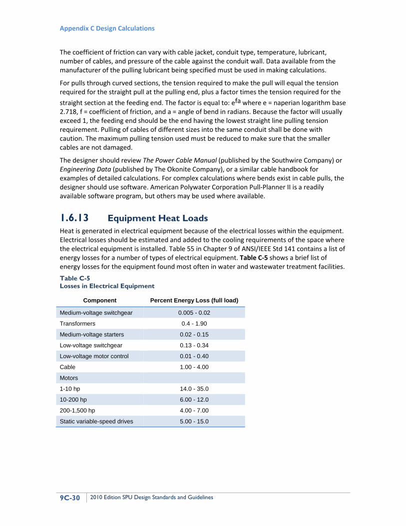
1.6.13 Equipment Heat Loads Heat is generated in electrical equipment because of the electrical losses within the equipment. Electrical losses should be estimated and added to the cooling requirements of the space where the electrical equipment is installed. Table 55 in Chapter 9 of ANSI/IEEE Std 141 contains a list of energy losses for a number of types of electrical equipment. Table C-5 shows a brief list of energy losses for the equipment found most often in water and wastewater treatment facilities. Table C-5 Losses in Electrical Equipment
Component Percent Energy Loss (full load)
Medium-voltage switchgear 0.005 - 0.02
Transformers 0.4 - 1.90
Medium-voltage starters 0.02 - 0.15
Low-voltage switchgear 0.13 - 0.34
Low-voltage motor control 0.01 - 0.40
Cable 1.00 - 4.00
Motors
1-10 hp 14.0 - 35.0
10-200 hp 6.00 - 12.0
200-1,500 hp 4.00 - 7.00
Static variable-speed drives 5.00 - 15.0