Embed Size (px)
Citation preview
The 5th PSU-UNS International Conference on Engineering and
Technology (ICET-2011), Phuket, May 2-3, 2011 Prince of Songkla University, Faculty of Engineering
Hat Yai, Songkhla, Thailand 90112
Abstract: This paper is a proposal for an advanced
approach for FEM modeling, structural analysis and
design of a jib structure which is a typical part of the
waterway bucket dredgers facilities. Dredgers with two
catamaran-like pontoons, with jib in between, are
considered here. The item of the analysis is the jib
structure which will be re-constructed for the excavation
of grain material from greater depths. Discussion here is
oriented to the explanation of advantages and problems
in the utilization of various FEM models.
Key Words: FEM Modeling, Jib Structure, Optimal
Design
1. INTRODUCTION
In the classification of the waterway dredgers for the
material exploitation under the water surface, a large
group is bucket dredgers with the bucket on the continual
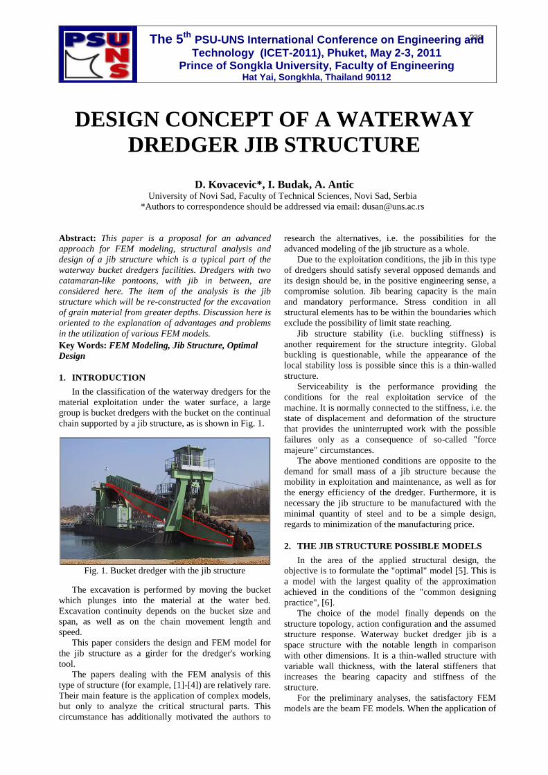
chain supported by a jib structure, as is shown in Fig. 1.
Fig. 1. Bucket dredger with the jib structure
The excavation is performed by moving the bucket
which plunges into the material at the water bed.
Excavation continuity depends on the bucket size and
span, as well as on the chain movement length and
speed.
This paper considers the design and FEM model for
the jib structure as a girder for the dredger's working
tool.
The papers dealing with the FEM analysis of this
type of structure (for example, [1]-[4]) are relatively rare.
Their main feature is the application of complex models,
but only to analyze the critical structural parts. This
circumstance has additionally motivated the authors to
research the alternatives, i.e. the possibilities for the
advanced modeling of the jib structure as a whole.
Due to the exploitation conditions, the jib in this type
of dredgers should satisfy several opposed demands and
its design should be, in the positive engineering sense, a
compromise solution. Jib bearing capacity is the main
and mandatory performance. Stress condition in all
structural elements has to be within the boundaries which
exclude the possibility of limit state reaching.
Jib structure stability (i.e. buckling stiffness) is
another requirement for the structure integrity. Global
buckling is questionable, while the appearance of the
local stability loss is possible since this is a thin-walled
structure.
Serviceability is the performance providing the
conditions for the real exploitation service of the
machine. It is normally connected to the stiffness, i.e. the
state of displacement and deformation of the structure
that provides the uninterrupted work with the possible
failures only as a consequence of so-called "force
majeure" circumstances.
The above mentioned conditions are opposite to the
demand for small mass of a jib structure because the
mobility in exploitation and maintenance, as well as for
the energy efficiency of the dredger. Furthermore, it is
necessary the jib structure to be manufactured with the
minimal quantity of steel and to be a simple design,
regards to minimization of the manufacturing price.
2. THE JIB STRUCTURE POSSIBLE MODELS
In the area of the applied structural design, the
objective is to formulate the "optimal" model [5]. This is
a model with the largest quality of the approximation
achieved in the conditions of the "common designing
practice", [6].
The choice of the model finally depends on the
structure topology, action configuration and the assumed
structure response. Waterway bucket dredger jib is a
space structure with the notable length in comparison
with other dimensions. It is a thin-walled structure with
variable wall thickness, with the lateral stiffeners that
increases the bearing capacity and stiffness of the
structure.
For the preliminary analyses, the satisfactory FEM
models are the beam FE models. When the application of
DESIGN CONCEPT OF A WATERWAY
DREDGER JIB STRUCTURE
D. Kovacevic*, I. Budak, A. Antic University of Novi Sad, Faculty of Technical Sciences, Novi Sad, Serbia
*Authors to correspondence should be addressed via email: [email protected]
239

these 1D models determines the approximate element
dimensions, they are followed by the sophisticated
analysis by applying the 2D FEM models with the
surface FE.
These 2D models almost completely satisfy the
demands of the developmental research, so they can be
the final models for the jib structural systems. The state
of stress and deformation in the jib thin-walled structure
can be approximated rather well by a model in which the
stresses in the normal direction on the plate surface that
present the jib cover are neglected. Furthermore, it is
reasonable to assume that there is no shear in the plate
mid-plane. These circumstances indicate the possibility
to utilize the model based on the Kirchhoff''s flexural
theory of thin plates, [5]. Exceptionally, for the plates
with relatively large thickness it is necessary to apply
the Reissner-Mindlin models for thick plate bending. If
one can avoid the appearance of the so-called "shear-
locking" phenomenon, the thick plate models that
consider the shear influence (i.e. real shear stiffness) can
provide very satisfactory results. Finally, if there is the
stress concentration in the local zones ("hot spot area"),
when the external action is distributed on a relatively
small surface, or if the stresses orthogonal to the plate
mid-plane cannot be neglected, the application of a 3D
model is an imperative.
A simple numerical test will illustrate the advantages
of a model with 2D FE in relation to the 1D FE model.
The results of this test could be main argument in the
final model choice. This and similar, "benchmark test"
should become an obligatory part in the model choice
methodology.
The analysis is performed for the vertical uniformly
distributed load equal to the weight of the chain with the
buckets. Fig. 2 presents 1D (top) and 2D (botom) models
and principal stress values, vertical displacements in
characteristic points and the lowest natural frequencies
for both models.
Fig. 2. 1D and 2D models: displacements principal
stresses and the lowest natural frequencies
1D model is formed from the beam FE (□240x
100x20mm box shape) and in the topological sense it is
completely identical to the 2D model with the
rectangular shell (isoparametric, nine-node, heterosis)
with the FE thickness of t=20mm. Boundary conditions
are adapted to the real conditions of the jib support.
It is clear that the principal stresses (S1 and S2) in the
more accurate 2D model are 1.75 to 11.75 times greater
than in a simpler 1D model. The case with the vertical
displacements (Dz) is similar. Here the factors are from
1.54 to 1.80 more beneficial to the more complex 2D
model.
Furthermore, the lowest natural frequency (f1) in a
1D model is almost 1.8 times lower than the same
frequency in the 2D model. It is necessary to note that
both models have the natural shape with horizontal
displacements.
These differences in the response for the same action
indicate the necessity of the application of the more
sophisticated model with 2D shell FE in modeling the jib
behavior. This test shows very clearly that apparently
similar models can obtain very diverse data about the
structure, and sometimes also a very wrong impression
about the bearing capacity, stability and serviceability,
thus definitely confirming the demand for applying more
complex models. In this sense, all further considerations
will apply to the numerical model with 2D shell FE.
3. FINAL MODEL OF THE JIB STRUCTURE
Because of new exploitation demands jib will be
reconstructed by increasing the length from 35.5m to
49.0m, Figure 3 (can be seen in [6]) shows the jib
structure with the marked position of the new additional
segment.
Fig. 3. Drawing of new length jib structure
The increase in the jib length has the following
consequences:
axial, flexural and torsional stiffness decrease and
inertia increase, i.e. natural frequencies decrease.
In the jib modeling, the software AxisVM® version
10.2h (InterCAD, Hungary) has been used. AxisVM® is
based on the pre-processor for geometric modeling, the
processor for numerical modeling (with the rich library
of FE and a large number of various models: linear,
nonlinear, dynamic, etc.) and the post- -processor for
presentation of the analysis results.
4. MODELING OF THE JIB STRUCTURE
TOPOLOGY AND GEOMETRY
Data on the jib structure topology and structural
elements dimensions are taken from [6].
For the geometric modeling of the jib structure, the
non-automatic approach for FE meshing has been
selected. The procedure has the following steps:
designing stiffeners (only one symmetric side) of
diverse type and dimensions, Fig. 4,
placing stiffeners at appropriate position, i.e.
forming the structure skeleton (symmetric side),
Fig. 5,
connecting stiffeners with the cover plates
(symmetric side), Fig. 6,
240

elaborating the support details - in the zone of the
axle around the jib rotates in the vertical plain and
in the zone of cable connected for the jib angle
changing, Fig. 7, and
adding the onother symmetric side, Fig. 8.
Fig. 4. Halves of the jib frame stiffeners
Fig. 5. Frame stiffeners (one side of structure)
Fig. 6. Cover plate segments between frame stiffeners
(one side of structure)
Fig. 7. Jib structure supports details
This approach has been selected with the objective to
minimize the FE mesh size, which can lead to the
efficiency of the computation. Furthermore, one obtains,
in the largest number, rectangular shape of the FE's,
without great shape distortion, which is the most
favorable solution from the aspect of the numerical error
in computations.
Fig. 8. Entire model of the jib structure
5. MODELING THE ELEMENTS, BOUNDARY
CONDITIONS AND ACTIONS
The concept of the model design described in the
previous paragraphs has been selected with the objective
to obtain a robust and efficient model in the numerical
sense: degrees of freedom (DOF) number is 140838 for
the model with 6525 nodes and 7188 shell FE.
Model rationality and calculation efficiency are
significant since they enable the following:
simple and rapid model changing,
various action modeling (loads, temperature
changes, support displacements, manufacturing
imperfections, accidental actions, etc.) and
various types of analyses (linear analysis,
geometric/material nonlinear analysis, buckling
analysis, free vibrations analysis, time history
analysis, etc.).
With the structural elements approximation there has
not been any great dilemma - rectangular shell FEs are
applied with nine nodes of the heterosis type and
triangular FE with seven nodes, based on the Reissner-
-Mindlin theory of thick plate bending and the theory for
membrane stress condition. Each node in this FE element
has all six degrees-of-freedom elements - three
translations and three rotations. It is important to
emphasize that the rotation DOF in the plane of the FE
(so-called "drilling" DOF) is introduced implicitly,
which is a satisfactory treatment. The size, shape and
distribution (and hence the number) of the FE is selected
in such a manner as to avoid the structurally and
numerically unwanted situations:
stress concentration (except when it is a necessity
due to the shape of the action) and
calculation errors that generate due to the
existence of the "distorted" shape of FE.
The next step demands a designer's creative efforts
regards to the modeling of behavior of the support zones
of the structural system, the places with abrupt stiffness
change with eccentricity, as well as the areas where the
structural elements are connected in a specific manner. It
is common in the FEM technology for this modeling to
be obtained by defining boundary and interface
conditions.
241

For the observed jib structure, the support conditions
are simple to model. The axle (Fig. 7, left) around which
the jib can rotate freely is the bearing that is by the
pedestal supported to the deck structure of the waterway
facility. It is necessary to model almost completely free
(or with little friction) only jib rotation around the axle
and without any other DOF. This can be obtained only
by applying the so-called link FE (for details see [7]).
Link FEs are used for modeling connections and
joints with special characteristics. These are 1D FE of
special purpose with two nodes and all six DOF in each
node. Usually, the connections of the standard FEs are
direct - in common nodes. If the connection between two
adjacent FE is without a common node, the link FE is
used. By varying the stiffness and position parameters
(the so-called interface points), one can model a set of
various connections. In the jib structure modeling, the
link FEs are applied in two cases: for the axle-jib
connection and for large number of eccentrically
connected joints between the jibs cover plates.
The connection jib/axle is a hinge which allows only
the rotation around the own axis. In Fig. 9 there is a
model of this hinge with the distribution of link FEs.
thinner part
of axle
thicker part
of axle
hinge part
of jib
thinner part
of axle FE
thicker part
of axle FE
hinge part
of jib FEssingle
link FE
Fig. 9. Modeling the hinged support by link FE
As it can be observed, link FEs radially join a node of
the FE axle and adjoining nodes of the shell FE of the jib
hinge.
Similar situation refers to all eccentric joints in the
thin-walled cover or diverse thickness stiffeners, as
presented in Fig. 10. Here, all six stiffness parameters
have a non-zero value that simulates a rigid welded
eccentric connection.
In some cases there is a necessity for such model
configuration of the eccentrically welded sheet metal
plates, especially if there are large membrane forces.
Fig. 10. Link FEs for connections with eccentricity
Jib configurations with various actions are: repair,
transportation and three dredging positions.
Actions are the following:
a) jib self-weight (G=76545.8kg),
b) empty buckets weight (qE=9.4kN/m),
c) filled buckets weight (qC=15.8kN/m),
d) bottom wheel weight (GBW=50kN),
e) dredging force (FD=273.5kN),
f) bucket chain pull force (FBC=560.7kN),
g) frontal force of extrude (FFI=150kN),
h) lateral force of extrude (FLI=77kN) and
i) pending part of chain weight (GPC=220kN).
Eight configurations have been observed:
jib is on the 12º in relation to the horizontal line -
repair and transportation positions,
jib is on the 18º - statuses "A", "B", and "C" and
jib is on the 45º - statuses "A", "B", and "C".
Valid configurations are as follows:
repair position: a)+b) - jib is supported by cable to
the bow crane (discussed later),
transportation position: a)+b)+c) - jib is supported
to the waterway bed,
status "A": a)+c)+d)+e)+f)+g)+h) - jib is
supported by cable to the dredger's bow crane,
status "B": a)+c)+d)+e)+f)+g)+h) - jib is
supported to the waterway bed and
status "C": a)+c)+d)+e)+f)+g)+h)+i) - jib is
supported by chain to the dredger's bow crane.
6. ANALYSIS OF THE JIB STRUCTURE
RESPONSE
Comparing the results of the analysis and the
calculations, it is established that, utilizing the criteria of
the greatest displacements and support responses, the
valid configurations are as follows:
"18C" - jib is on the 18º - status "C",
"18B" - jib is on the 18º - status "B",
"45C" - jib is on the 45º - status "C" and
"45B" - jib is on the 45º - status "B".
Hence, the characteristic values only for these four
configurations will be presented here. In the Table 1 are
242

the maximal displacement values in the jib's own
coordinate system.
Table 1. Maximum jib displacements (own
coordinate system)
x-displacement
[mm]
y-displacement
[mm]
z-displacement
[mm]
18C 32.14 112.11 36.08
18B 44.62≈L/1098 -71.66 48.74
45C 12.49 12.53≈L/435 52.32≈L/937
45B 6.94 -71.61 -34.50
Figures 11-14 show only the permitted stress
(σperm=16.0kN/cm2) overflow zones. It is important to
emphasize that the stress overflow in the jib support to
the waterway bed zone (configuration "B") is primarily
the consequence of simplifying the numerical model in
this segment of the jib structure. Namely, it is justifiable
to assume that the equipment not introduced into the
model (wheel, axle, engine, etc.) would significantly
contribute to the jib stiffness.
Figure 11. Principal stresses overflow in "18C"
Figure 12. Principal stresses overflow in "18B"
Fig. 13. Principal stresses overflow in "18C"
Fig. 14. Principal stresses overflow in "18B"
7. CONCLUSIONS
From the above stated observations, it is clear that the
jib structural analysis, as a very complex task, demand
for the attention to be directed towards modeling, not
only of the structure elements, but also of the conditions
of supports and connections between structural elements.
It has been emphasized and presented in the
beginning that the simple 1D model has drawbacks that
disqualify them in the selection of the final jib model.
In connection modeling, a special attention is
provided for the link FE that enables the simulation of
almost all transitional conditions.
A model with this level of complexity and accuracy
enables a detailed insight into the jib structure behavior
under load. On the other side, the proposed model and
modeling algorithm can also be considered optimal since
they are adapted to the conditions of everyday design
practice.
8. REFERENCES
[1] Rusiński, E., Czmochowski, J., Moczko, P.
"Numerical and Experimental Analysis of a Mine’s
Loader Boom Crack", Journal of Automation in
Construction, 2008, Vol. 17, pp. 271-277.
[2] Shinde, S. D. "Standardization of Jib Crane Design
by F.E.M. Rules and Parametric Modelling",
International Journal of Recent Trends in
Engineering, 2009, Vol. 1, No. 5, pp. 145-149.
[3] López, V. D. "Finite Element Crane Analysis
According to UNE 58132-2 Standard", 2008,
University of Carlos III, Madrid.
[4] Vlasblom, W.J. "Dredging Equipment and
Technology, Ch. 6 - Bucket (Ladder) Dredger", 2004,
Delft University of Technology.
[5] Kovačević, D. "FEM Modelling in Structural
Analysis" (in Serbian), Građevinska knjiga, 2006,
Belgrade.
[6] Kovačević, D. "Numerical analysis and computation
of the jib structure of waterway bucket dredger -
Technical report", Ship Registry of Republic of
Serbia, 2009.
[7] Kovačević, D, Folić, R. "Some Aspects of FEM
Structural Modelling by Link FE", Proceedings of the
11th International Conference on Civil, Structural
and Environmental Engineering Computing -
CC2007, Malta, 2007. pp. 211-226.
243


![Pillar and wall-mounted slewing jib cranes · Max. load capacity [kg] Electric slewing Pillar-mounted slewing jib cranes Wall-mounted slewing jib cranes Jib type/design Max. outreach](https://img.pdfslide.net/doc/110x75/5b535fa87f8b9ae30b8be93d/pillar-and-wall-mounted-slewing-jib-cranes-max-load-capacity-kg-electric.jpg)