Embed Size (px)
Citation preview
Received December 29, 2018, accepted January 3, 2019, date of publication January 18, 2019, date of current version February 8, 2019.
Digital Object Identifier 10.1109/ACCESS.2019.2893313
Design Considerations for IntegratedRadar Chirp SynthesizersDANIEL WEYER 1,2, (Member, IEEE), MEHMET BATUHAN DAYANIK 3, (Member, IEEE),LU JIE 2, (Student Member, IEEE), AHMED ALBALAWI4, ABDULHAMED ALOTHAIMEN4,MOHAMMED ASEERI 4, (Member, IEEE), AND MICHAEL P. FLYNN 2, (Fellow, IEEE)1Silicon Laboratories Inc., Austin, TX 78701, USA2Department of Electrical Engineering and Computer Science, University of Michigan, Ann Arbor, MI 48109, USA3Broadcom Ltd., Irvine, CA 92618, USA4King Abdulaziz City for Science and Technology, Riyadh 12354, Saudi Arabia
Corresponding author: Daniel Weyer ([email protected])
This work was supported in part by the Microwave Sensor Technology Center.
ABSTRACT Phase-locked loops (PLLs) effectively generate frequency chirps for frequency-modulatedcontinuous-wave (FMCW) radar and are ideal for integrated circuit implementations. This paper discussesthe design requirements for integrated PLLs used as chirp synthesizers for FMCW radar and focuses onan analysis of the radar performance based on the PLL configuration. The fundamental principles of theFMCW radar are reviewed, and the importance of low synthesizer phase noise for reliable target detection isquantified. This paper provides guidance for the design of chirp synthesizer PLLs by analyzing the impact ofthe PLL configuration on the accuracy and reliability of the radar. The presented analysis approach allowsfor a straightforward study of the radar performance and quantifies the optimal settings of a PLL-basedchirp synthesizer for a given application scenario, while the developed methodology can be easily appliedto other scenarios. A novel digital chirp synthesizer PLL design that meets the requirements of FMCWradar is presented. The synthesizer prototype fabricated in 65-nm CMOS drives a radar testbed to verify theeffectiveness of the synthesizer design in a complete FMCW radar system.
INDEX TERMS Chirp linearity, chirp synthesis, frequency-modulated continuous-wave (FMCW) radar,fully-integrated chirp synthesizer, phase locked loop (PLL), phase noise, PLL bandwidth, radar testbed.
I. INTRODUCTIONRadar applications for driver assistance systems andautonomous vehicles have spurred the development offrequency-modulated continuous-wave (FMCW) radar [1].FMCW radar relies on accurate frequency modulation ofa continuously transmitted signal to measure target proper-ties [2]. Unlike more traditional radar schemes that use pulsesand operate in the MHz- or lower GHz-range, FMCW radarfor the K- or W-bands offers lower power consumption andcan be realized with much smaller form factors. Advancesin silicon technology and the increasing demand for power-efficient, compact and low-cost high-frequency FMCW radarhave motivated research on single-chip waveform synthesiz-ers [3]–[5] and fully-integrated transceiver systems [6]–[8].
Fractional-N phase locked loops (PLLs) which digitallymodulate the division ratio of the feedback divider are aneffective tool for synthesis of FMCW. The performancerequirements of the radar system, however, pose signifi-cant challenges and trade-offs for the design of PLL-based
FMCW chirp synthesizers. With the assumption of linearchirps, FMCW radar determines target range and relativevelocity from the frequency difference between transmittedand received signals, as described in detail in Section II. A keyperformance characteristic of the chirp synthesizer PLL is thephase noise. In an FMCW radar, the transmit signal is alsoused to down-convert the receive signal. The target propertiesare calculated from the low-frequency baseband signal result-ing from the down-conversion. For slow to moderate-speedchirps, this baseband signal falls into the close-in phase noiseregion of the synthesizer. High phase noise levels reduce thesignal-to-noise ratio (SNR) or may even mask the basebandsignal. As discussed in detail in Section III, low close-in phasenoise is crucial for high detection sensitivity of the radar.
The stair-step approximation of the chirp signal leads totrade-offs in the choice of the bandwidth of the PLL. Digitalmodulation of the feedback divider approximates the desiredFMCW waveform as a sequence of discrete frequency levelswith a certain stepping rate. On the one hand, the PLL must
VOLUME 7, 20192169-3536 2019 IEEE. Translations and content mining are permitted for academic research only.
Personal use is also permitted, but republication/redistribution requires IEEE permission.See http://www.ieee.org/publications_standards/publications/rights/index.html for more information.
13723
D. Weyer et al.: Design Considerations for Integrated Radar Chirp Synthesizers
exhibit settling behavior fast enough for the PLL output fre-quency to follow the modulation signal. This calls for a PLLloop bandwidth that is much larger than the chirp modulationfrequency. On the other hand, the PLL bandwidth must besmaller than the stepping rate to ensure that the PLL doesnot output the stair-like approximation, which would resultin degraded chirp linearity. For high chirp linearity and toguarantee accurate target detection, the PLL bandwidth mustbe carefully chosen for a given application scenario.
Previous works have studied synthesizer bandwidth andchirp non-linearity and to some extent their effects on theradar performance. Chirp linearity has been expressed as afunction of synthesizer bandwidth by deriving the linearitybased on a Fourier series [9]. However, this analysis doesnot consider the effect of digital modulation in a PLL-basedsynthesizer. Also, it does not provide insight into the qualityof the radar as it is not conducted within the context of acomplete radar system. Furthermore, the effects of sinusoidalnon-linearities in the frequency chirp on the receiver base-band spectrum have been studied, but the non-linearities arenot related to the synthesizer bandwidth and thus do not offerpractical guidance for the design of a PLL-based synthe-sizer [10]. In this paper, we analyze PLL bandwidth and chirplinearity based on a model of a complete radar system. Ouranalysis incorporates a detailed model of a PLL-based chirpsynthesizer and considers design aspects of the DSP back-end as well. We examine the impact of the PLL bandwidthon the radar performance and quantify the upper and lowerbounds of the PLL bandwidth, considering slow and fast chirpmodulation. The presented modeling approach allows for astraightforward study of the radar accuracy and reliabilityas functions of the chirp parameters and the synthesizerPLL configuration.
Although general guidelines can be given regarding thedesign of an FMCW chirp synthesizer PLL, it is hard toevaluate synthesizer performance and provide design guid-ance without a specific application scenario. We choose thewell-known 77GHz standard for long-range automotive radar(LRAR) to examine PLL requirements and analyze radarperformance. The methodology developed in this paper canbe easily applied to other scenarios. In the paper, we referto component performance reported in the literature for inte-grated 77GHz radar systems listed in Table 1.
In addition, this paper presents a novel PLL-based chirpsynthesizer implementation and describes an experimentalsetup to test the effectiveness of the synthesizer. While fully-integrated synthesizer PLLs can be implemented as ana-log or digital PLLs, analog implementations still dominate athigh frequencies. Digital PLLs offer greater programmabilityand area efficiency, but suffer from performance limitationsof conventional time-to-digital converters (TDCs), in partic-ular poor time resolution, which severely limits the close-inphase noise of the PLL. This shortcoming of digital PLLsbecomes even more pronounced with the wide loop band-widths required for FMCW radar, as wide-loop-bandwidthPLLs allow more phase detector (or TDC) noise through
TABLE 1. Component values for 77GHz radar scenario.
to the PLL output. Binary TDCs (also referred to as bang-bang phase detectors) can be a useful alternative to addressthe resolution-power trade-off designers face with conven-tional TDCs, offering low power consumption thanks to theirsimplicity. A chirp synthesizer PLL using a binary TDC canbe implemented with a two-point modulation (TPM) schemefor fast frequency modulation with a narrow PLL bandwidth.In fact, TPM has emerged as a popular approach to solve thetrade-off between PLL bandwidth and phase noise [3], [5],but such PLL designs must apply calibration to address thegain mismatch between the modulation paths. We present adigital synthesizer implemented as a single-loop digital PLLthat meets the conflicting requirement of low close-in phasenoise and wide PLL bandwidth. This design succeeds byusing a novel TDC architecture that combines a conventionalanalog phase-frequency detector (PFD) and charge pumpwith a continuous-time 16 modulator.The paper is organized as follows: Section II begins with a
theoretical discussion based on an overview of the principlesof FMCW radar. Section III discusses the impacts of synthe-sizer phase noise. Section IV focuses on the loop bandwidthof an FMCW synthesizer PLL with an analysis supported bysimulation results. Section V presents our novel PLL-basedFMCW synthesizer design. Section VI describes a completeend-to-end radar testbed that demonstrates the effectivenessof the synthesizer architecture in a complete radar system.Section VII concludes the paper.
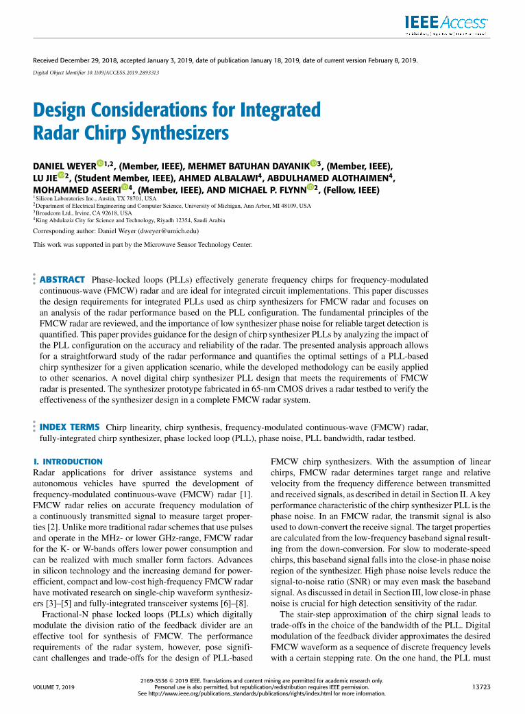
II. FMCW RADARAn FMCW radar continuously transmits a signal whose fre-quency is linearly modulated during the measurement. Themost commonly used chirp profiles are sawtooth and triangu-lar profiles, as illustrated in Fig. 1. We observe a propagationdelay between the transmitted and received signals due tothe signal roundtrip. Further, the received signal frequencyexperiences a Doppler shift if the target is moving relative tothe radar. The resulting offset frequency between transmittedand received signal is referred to as the beat frequency andrepresents a measure of target range and velocity. For a saw-tooth profile (Fig. 1(a)), we can express the beat frequencyas
fb =2R BWc T
+ fd (1)
where R denotes the target range, BW the chirp modulationbandwidth, c the speed of light, T the modulation period,
13724 VOLUME 7, 2019
D. Weyer et al.: Design Considerations for Integrated Radar Chirp Synthesizers
FIGURE 1. Sawtooth FMCW chirp (a) and triangular FMCW chirp (b).
and fd the Doppler frequency [1]. To unambiguously resolvethe range, R, and relative velocity, v = cfd /(2 fc), wherefc represents the center frequency of the waveform,a sequence of chirps with different ramp slopes can begenerated.
Using a triangular waveform profile (Fig. 1(b)), however,we obtain two distinct beat frequencies (f upb , f dnb ) from theup- and down-chirps and can unambiguously calculate rangeand velocity as [7]
R =c T4 BW
·f upb + f
dnb
2(2)
v =c2 fc·f upb − f
dnb
2(3)
High resolution in range and velocity measurements iscritical for target separability. If we assume that the beatsignal period is limited by the duration of the up- and down-chirps, then the minimum detectable beat frequency (and beatfrequency difference) is 2/T , and we can derive the range andvelocity resolutions as
1R =c
2BW(4)
1v =c
2 fc T(5)
Accordingly, the radar requires a large modulation bandwidthfor fine range resolution, whereas a longer period of thetriangular chirp improves the velocity resolution. Althoughequations (4) and (5) describe the ideally achievable resolu-tions, the actual values are further limited by several factorsincluding the overlap of the transmitted and received chirpsdue to the signal propagation delay, time gating to discardhighly nonlinear chirp segments near the chirp turnaroundpoints, and, most importantly, chirp non-linearity [9], [10].
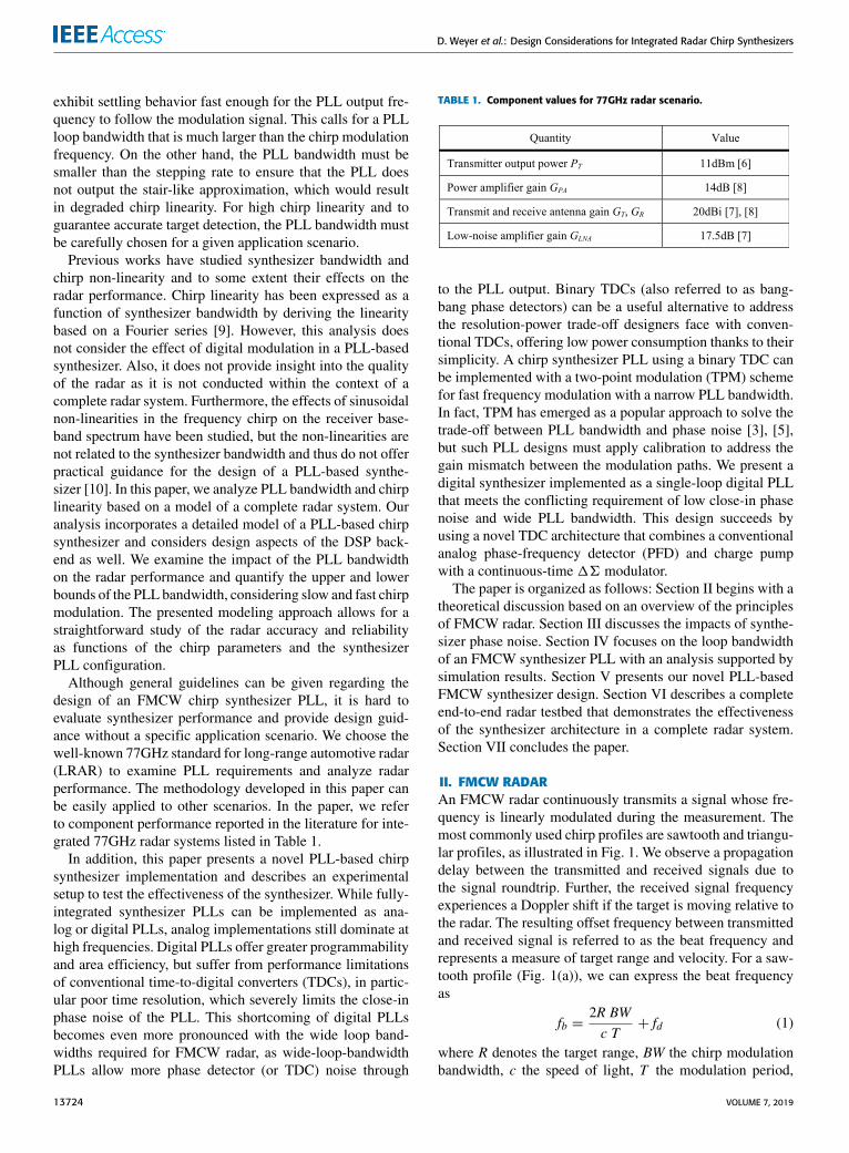
A block schematic of a complete FMCW radar systemis shown in Fig. 2. The chirp synthesizer generates theFMCW signal and a power amplifier (PA) feeds the syn-thesizer output signal to the transmit antenna. A receiveantenna picks up the returned signal, which is then mixedwith the synthesizer output to obtain the beat frequencies. TheDSP back-end performs an FFT on the digitized basebandsignal to determine the beat frequencies and calculates dis-tance and velocity of the target.
FIGURE 2. FMCW radar system.
To gain insight into the design challenges of the radarsystem, it is instructive to study the radar link budget. Thereceive power PR of the transceiver is given as
PR =PTGTGRσλ2
(4π )3R4(6)
where PT denotes the transmit power, GT and GR are thetransmit and receive antenna gain, respectively, σ is the radarcross section (RCS), λ is the wavelength and R is the range ofthe target [11]. We evaluate (6) for a potential fully-integratedCMOS radar, assuming the LRAR scenario. The RCS of amid-sized car varies greatly with the incident angle of theradar signal [1]. We assume an RCS of 30m2 at the rear ofthe car [7]. Using 100m as a typical target range for LRAR,the specifications in Table 1 yield a receive power of -95dBm.Such a low power level makes it challenging to achieve areceive SNR that guarantees reliable target detection. Forreliable detection with a low false-alarm rate, the SNR mustexceed a certain threshold SNR. Values given in the literaturevary and are in the range of 10 to 16dB [1], [11], requiring thenoise floor to be at around −110dBm. Several noise sourcescontribute to the total noise at the receive back-end andinclude the phase noise from the chirp synthesizer, the low-noise amplifier (LNA) noise and the quantization noise of theanalog-to-digital converter (ADC).
III. SYNTHESIZER PHASE NOISEAn FMCW radar system uses the transmit signal to down-convert the receive signal (Fig. 2). For slow and moder-ate chirp slopes, the beat frequencies typically fall into theclose-in phase noise region of the synthesizer and may bemasked by the phase noise. Moreover, in multi-target sce-narios, reflected signal powers are likely to vary significantlyand the phase noise reflected by targets with strong reflectionmay mask other targets. Low close-in synthesizer phase noiseis therefore crucial for reliable target detection.
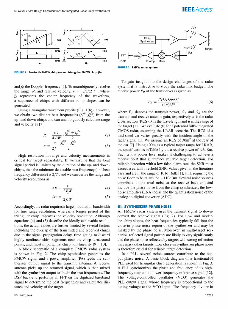
In a PLL, several noise sources contribute to the out-put phase noise. A basic block diagram of a fractional-NPLL used for triangular chirp generation is shown in Fig. 3.A PLL synchronizes the phase and frequency of its high-frequency output to a lower-frequency reference signal [12].The voltage-controlled oscillator (VCO) generates thePLL output signal whose frequency is proportional to thetuning voltage at the VCO input. The frequency divider in
VOLUME 7, 2019 13725
D. Weyer et al.: Design Considerations for Integrated Radar Chirp Synthesizers
FIGURE 3. Fractional-N PLL with chirp control unit for FMCW chirpsynthesis.
FIGURE 4. Noise spectrum at mixer output with beat frequency withinclose-in phase noise region.
the feedback path of the PLL divides the VCO output fre-quency, producing an output signal whose frequency is equalto (or during start-up at least close to) the PLL referencefrequency. The phase detector (PD) measures the phase dif-ference between the reference clock and the feedback signal.Finally, the loop filter stabilizes the feedback loop, smoothingthe PD output and providing the tuning voltage for the VCO.Fractional division is accomplished by using a16modulatorto switch the division ratio of the programmable dividerbetween different integer values so that the average value isequal to the desired fractional value [13].
Reference noise, phase detector noise, divider noise and16 quantization noise can be referred to the reference nodeof the PLL. The combined noise contribution at this node,which is typically dominated by the phase detector noiseat low frequency offsets, is low-pass filtered by the PLLand determines the close-in phase noise. In contrast, theVCO noise is high-pass filtered and dominates the PLL phasenoise at large frequency offsets. The amount of phase detectornoise getting through to the PLL output increases with thePLL bandwidth, whereas more VCO noise is suppressed witha larger PLL bandwidth. Fast chirp modulation requires fastPLL settling behavior, which translates to a wide PLL band-width. Thus, low phase detector noise (i.e. highly accuratephase detection) is critical for low close-in phase noise.
The phase noise profile given in Fig. 4 shows a realisticphase noise characteristic with a plateau-like region at lowand moderate frequency offsets as typically seen with wide-bandwidth PLLs and accounts for flicker noise (higher noiselevel at low offsets). As the location of the beat frequencysuggests, lower close-in phase noise improves the SNR inthe radar receiver. Although other potential measures suchas higher amplification in the transmit PA or a high-gain
LNA can provide some remedy, good close-in phase perfor-mance is imperative for the synthesizer in order to ensurereliable target detection.
The power of the receive signal at the mixer input equalsthe receive power PR multiplied by the gain, GLNA, ofthe LNA and must surpass the phase noise level L(fb) of thesynthesizer [14]. Taking into account that a certain detectionthreshold SNRmin must be met, we can derive an estimate ofthe maximum close-in phase noise level according to
10 · log10GPAGTGRGLNAσλ2
(4π)3R4≥ L(fb)+ SNRmin (7)
We again use the component values in Table 1 for theLRAR scenario and assume SNRmin = 15dB, σ = 30m2 andR = 100m. In this case, (7) yields a maximum close-in phasenoise level of−90dBc/Hz. Considering results reported in theliterature [6], [7], this close-in phase noise is challenging toachieve at 77GHz.
However, we must note here that transmitter phase noiseand receiver phase noise are in fact correlated, which is notaccounted for by (7). Since the receive signal is mixed withthe transmit signal, this noise correlation cancels phase noise,thus relaxing the phase noise requirement and increasing thesensitivity of the radar. The effectiveness of the cancellationdepends on the target range as well as the frequency offset.Reference [15] investigates the effect of range correlation onthe baseband (or IF) spectrum by formulating the basebandspectrum as a combination of the transmitter phase noisespectrum, scatterer spectra and range correlation effects. Theresidual phase noise present after mixing in the basebandsignal can be expressed as 18(t) = 8(t − td ) − 8(t),where8(t) describes the transmitter phase noise and td is theround-trip propagation delay of the radar signal. To quantifythe phase noise cancellation, [15] derives the baseband phasenoise spectrum as
S18(f ,R) = S8(f ) · [4 sin2(2π R f /c)] (8)
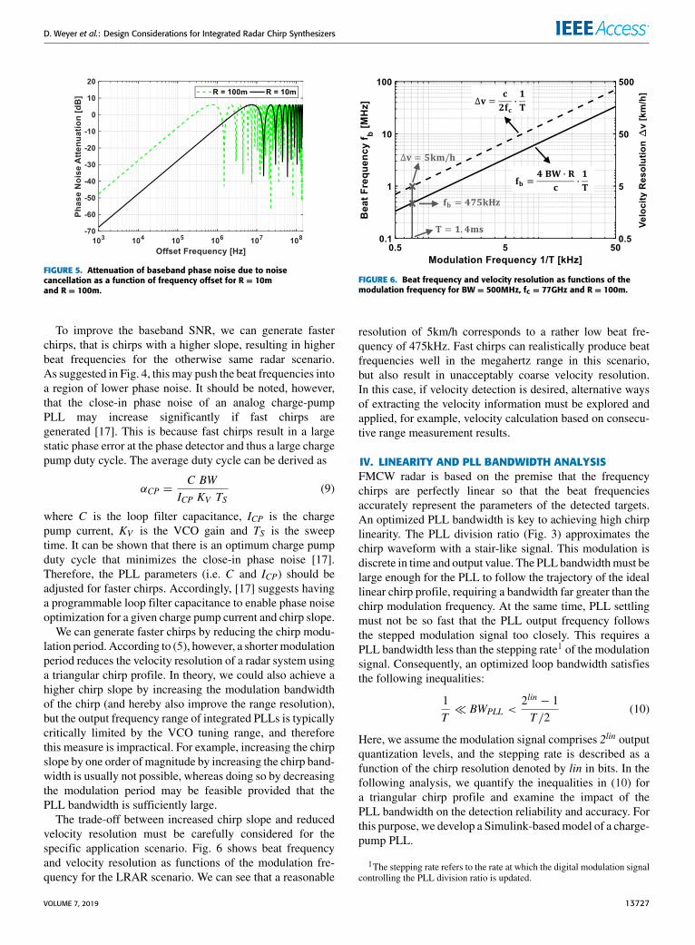
where S8(f ) is the phase noise spectrum of the transmitter.From the term in square brackets in (8), we can see that thenoise cancellation is more effective for low frequency offsetsand for close targets. As an example, for a 100kHz offset,the phase noise attenuation is −27.6dB for R = 10mand −7.6dB for R = 100m, respectively. Fig. 5 showsthe attenuation as a function of the frequency offset forR = 10m and R = 100m. Clearly, range correlation signif-icantly reduces the low-frequency phase noise componentsin the baseband spectrum. Therefore, we can think of (7) asgiving a pessimistic upper bound for the required phase noiseperformance. Finally, we can use (8) to study the influenceof phase noise on the system performance while taking noisecancellation into account. This is done in [16], which calcu-lates the rms phase error of the baseband signal based on (8)and uses this result to derive a lower bound for the uncertaintyin the range measurement. However, the ranging uncertaintyshown in [16] for a LRAR scenario is less than 1cm, whichcan be considered negligible.
13726 VOLUME 7, 2019
D. Weyer et al.: Design Considerations for Integrated Radar Chirp Synthesizers
FIGURE 5. Attenuation of baseband phase noise due to noisecancellation as a function of frequency offset for R = 10mand R = 100m.
To improve the baseband SNR, we can generate fasterchirps, that is chirps with a higher slope, resulting in higherbeat frequencies for the otherwise same radar scenario.As suggested in Fig. 4, this may push the beat frequencies intoa region of lower phase noise. It should be noted, however,that the close-in phase noise of an analog charge-pumpPLL may increase significantly if fast chirps aregenerated [17]. This is because fast chirps result in a largestatic phase error at the phase detector and thus a large chargepump duty cycle. The average duty cycle can be derived as
αCP =C BW
ICP KV TS(9)
where C is the loop filter capacitance, ICP is the chargepump current, KV is the VCO gain and TS is the sweeptime. It can be shown that there is an optimum charge pumpduty cycle that minimizes the close-in phase noise [17].Therefore, the PLL parameters (i.e. C and ICP) should beadjusted for faster chirps. Accordingly, [17] suggests havinga programmable loop filter capacitance to enable phase noiseoptimization for a given charge pump current and chirp slope.
We can generate faster chirps by reducing the chirp modu-lation period. According to (5), however, a shortermodulationperiod reduces the velocity resolution of a radar system usinga triangular chirp profile. In theory, we could also achieve ahigher chirp slope by increasing the modulation bandwidthof the chirp (and hereby also improve the range resolution),but the output frequency range of integrated PLLs is typicallycritically limited by the VCO tuning range, and thereforethis measure is impractical. For example, increasing the chirpslope by one order of magnitude by increasing the chirp band-width is usually not possible, whereas doing so by decreasingthe modulation period may be feasible provided that thePLL bandwidth is sufficiently large.
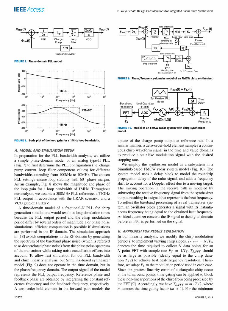
The trade-off between increased chirp slope and reducedvelocity resolution must be carefully considered for thespecific application scenario. Fig. 6 shows beat frequencyand velocity resolution as functions of the modulation fre-quency for the LRAR scenario. We can see that a reasonable
FIGURE 6. Beat frequency and velocity resolution as functions of themodulation frequency for BW = 500MHz, fc = 77GHz and R = 100m.
resolution of 5km/h corresponds to a rather low beat fre-quency of 475kHz. Fast chirps can realistically produce beatfrequencies well in the megahertz range in this scenario,but also result in unacceptably coarse velocity resolution.In this case, if velocity detection is desired, alternative waysof extracting the velocity information must be explored andapplied, for example, velocity calculation based on consecu-tive range measurement results.
IV. LINEARITY AND PLL BANDWIDTH ANALYSISFMCW radar is based on the premise that the frequencychirps are perfectly linear so that the beat frequenciesaccurately represent the parameters of the detected targets.An optimized PLL bandwidth is key to achieving high chirplinearity. The PLL division ratio (Fig. 3) approximates thechirp waveform with a stair-like signal. This modulation isdiscrete in time and output value. The PLL bandwidthmust belarge enough for the PLL to follow the trajectory of the ideallinear chirp profile, requiring a bandwidth far greater than thechirp modulation frequency. At the same time, PLL settlingmust not be so fast that the PLL output frequency followsthe stepped modulation signal too closely. This requires aPLL bandwidth less than the stepping rate1 of the modulationsignal. Consequently, an optimized loop bandwidth satisfiesthe following inequalities:
1T� BWPLL <
2lin − 1T/2
(10)
Here, we assume the modulation signal comprises 2lin outputquantization levels, and the stepping rate is described as afunction of the chirp resolution denoted by lin in bits. In thefollowing analysis, we quantify the inequalities in (10) fora triangular chirp profile and examine the impact of thePLL bandwidth on the detection reliability and accuracy. Forthis purpose, we develop a Simulink-basedmodel of a charge-pump PLL.
1The stepping rate refers to the rate at which the digital modulation signalcontrolling the PLL division ratio is updated.
VOLUME 7, 2019 13727
D. Weyer et al.: Design Considerations for Integrated Radar Chirp Synthesizers
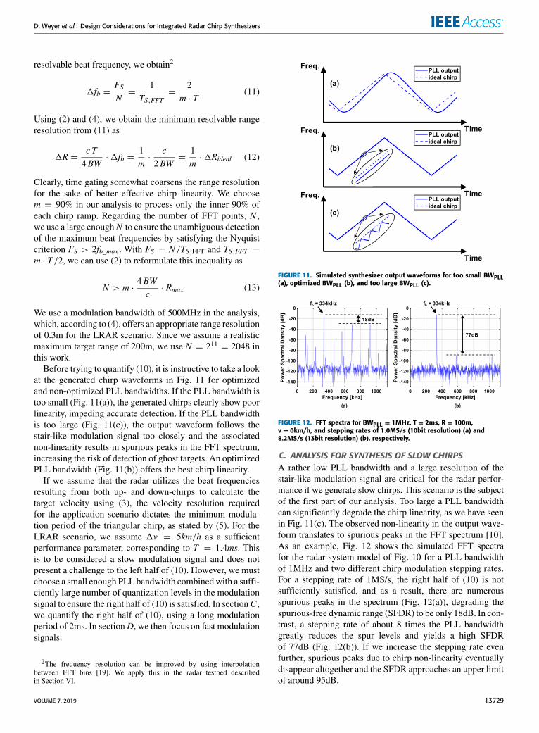
FIGURE 7. Phase-domain PLL model.
FIGURE 8. Bode plot of the loop gain for a 1MHz loop bandwidth.
A. MODEL AND SIMULATION SETUPIn preparation for the PLL bandwidth analysis, we utilizea simple phase-domain model of an analog type-II PLL(Fig. 7) to first determine the PLL configuration (i.e. chargepump current, loop filter component values) for differentbandwidths extending from 100kHz to 10MHz. The chosenPLL settings ensure loop stability with 60◦ phase margin.As an example, Fig. 8 shows the magnitude and phase ofthe loop gain for a loop bandwidth of 1MHz. Throughoutour analysis, we assume a 500MHz PLL reference, a 77GHzPLL output in accordance with the LRAR scenario, and aVCO gain of 1GHz/V.
A time-domain model of a fractional-N PLL for chirpgeneration simulations would result in long simulation timesbecause the PLL output period and the chirp modulationperiod differ by several orders of magnitude. For phase noisesimulations, efficient computation is possible if simulationsare performed in the IF domain. The simulation approachin [18] avoids computations in the RF domain by generatingthe spectrum of the baseband phase noise (which is referredto as decorrelated phase noise) from the phase noise spectrumof the transmitter while taking noise cancellation effects intoaccount. To allow fast simulation for our PLL bandwidthand chirp linearity analysis, our Simulink-based synthesizermodel (Fig. 9) does not operate in the time domain, but inthe phase/frequency domain. The output signal of the modelrepresents the PLL output frequency. Reference phase andfeedback phase are obtained by integrating the constant ref-erence frequency and the feedback frequency, respectively.A zero-order-hold element in the forward path models the
FIGURE 9. Phase/Frequency-domain model of an FMCW chirp synthesizer.
FIGURE 10. Model of an FMCW radar system with chirp synthesizermodel.
update of the charge pump output at reference rate. In asimilar manner, a zero-order-hold element samples a contin-uous chirp waveform signal in the time and value domainsto produce a stair-like modulation signal with the desiredstepping rate.
We employ the synthesizer model as a subsystem in aSimulink-based FMCW radar system model (Fig. 10). Thesystem model uses a delay block to model the roundtrippropagation delay of the radar signal, and adds a frequencyshift to account for a Doppler effect due to a moving target.The mixing operation in the receive path is modeled bysubtracting the receive frequency signal from the synthesizeroutput, resulting in a signal that represents the beat frequency.To reflect the baseband processing of a real transceiver sys-tem, an oscillator block generates a signal with its instanta-neous frequency being equal to the obtained beat frequency.An ideal quantizer converts the IF signal to the digital domainbefore an FFT is performed on the signal.
B. APPROACH FOR RESULT EVALUATIONIn our linearity analysis, we modify the chirp modulationperiod T to implement varying chirp slopes. TS,FFT = N/FSdenotes the time required to collect N data points for anN -point FFT with sample rate FS = 1/TS . TS,FFT shouldbe as large as possible (ideally equal to the chirp dura-tion T/2) to achieve best beat-frequency resolution. There-fore, we adapt FS to the modulation period used in each case.Since the greatest linearity errors of a triangular chirp occurat the turnaround points, time gating can be applied to blockthese non-linear portions of the chirp from being processed bythe FFT [9]. Accordingly, we have TS,FFT = m · T/2, wherem denotes the time gating factor (m < 1). For the minimum
13728 VOLUME 7, 2019
D. Weyer et al.: Design Considerations for Integrated Radar Chirp Synthesizers
resolvable beat frequency, we obtain2
1fb =FSN=
1TS,FFT
=2
m · T(11)
Using (2) and (4), we obtain the minimum resolvable rangeresolution from (11) as
1R =c T4BW
·1fb =1m·
c2BW
=1m·1Rideal (12)
Clearly, time gating somewhat coarsens the range resolutionfor the sake of better effective chirp linearity. We choosem = 90% in our analysis to process only the inner 90% ofeach chirp ramp. Regarding the number of FFT points, N ,we use a large enoughN to ensure the unambiguous detectionof the maximum beat frequencies by satisfying the Nyquistcriterion FS > 2fb_max . With FS = N/TS,FFT and TS,FFT =m · T/2, we can use (2) to reformulate this inequality as
N > m ·4BWc· Rmax (13)
We use a modulation bandwidth of 500MHz in the analysis,which, according to (4), offers an appropriate range resolutionof 0.3m for the LRAR scenario. Since we assume a realisticmaximum target range of 200m, we use N = 211 = 2048 inthis work.
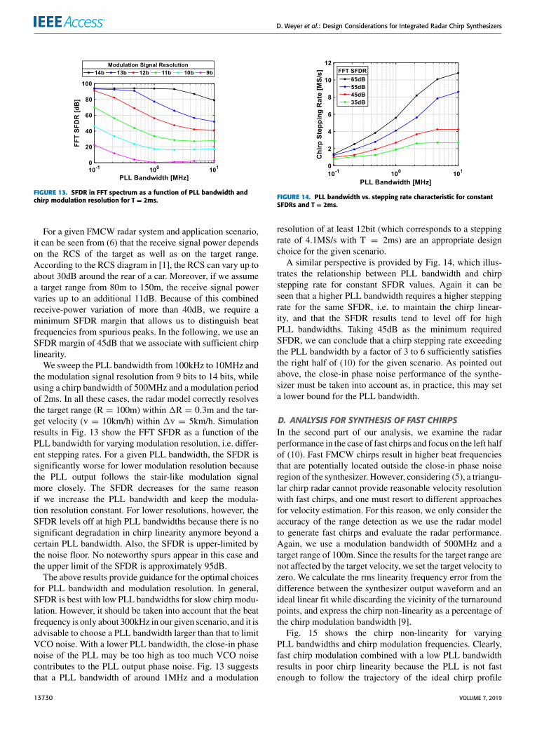
Before trying to quantify (10), it is instructive to take a lookat the generated chirp waveforms in Fig. 11 for optimizedand non-optimized PLL bandwidths. If the PLL bandwidth istoo small (Fig. 11(a)), the generated chirps clearly show poorlinearity, impeding accurate detection. If the PLL bandwidthis too large (Fig. 11(c)), the output waveform follows thestair-like modulation signal too closely and the associatednon-linearity results in spurious peaks in the FFT spectrum,increasing the risk of detection of ghost targets. An optimizedPLL bandwidth (Fig. 11(b)) offers the best chirp linearity.
If we assume that the radar utilizes the beat frequenciesresulting from both up- and down-chirps to calculate thetarget velocity using (3), the velocity resolution requiredfor the application scenario dictates the minimum modula-tion period of the triangular chirp, as stated by (5). For theLRAR scenario, we assume 1v = 5km/h as a sufficientperformance parameter, corresponding to T = 1.4ms. Thisis to be considered a slow modulation signal and does notpresent a challenge to the left half of (10). However, we mustchoose a small enough PLL bandwidth combinedwith a suffi-ciently large number of quantization levels in the modulationsignal to ensure the right half of (10) is satisfied. In sectionC ,we quantify the right half of (10), using a long modulationperiod of 2ms. In sectionD, we then focus on fast modulationsignals.
2The frequency resolution can be improved by using interpolationbetween FFT bins [19]. We apply this in the radar testbed describedin Section VI.
FIGURE 11. Simulated synthesizer output waveforms for too small BWPLL(a), optimized BWPLL (b), and too large BWPLL (c).
FIGURE 12. FFT spectra for BWPLL = 1MHz, T = 2ms, R = 100m,v = 0km/h, and stepping rates of 1.0MS/s (10bit resolution) (a) and8.2MS/s (13bit resolution) (b), respectively.
C. ANALYSIS FOR SYNTHESIS OF SLOW CHIRPSA rather low PLL bandwidth and a large resolution of thestair-like modulation signal are critical for the radar perfor-mance if we generate slow chirps. This scenario is the subjectof the first part of our analysis. Too large a PLL bandwidthcan significantly degrade the chirp linearity, as we have seenin Fig. 11(c). The observed non-linearity in the output wave-form translates to spurious peaks in the FFT spectrum [10].As an example, Fig. 12 shows the simulated FFT spectrafor the radar system model of Fig. 10 for a PLL bandwidthof 1MHz and two different chirp modulation stepping rates.For a stepping rate of 1MS/s, the right half of (10) is notsufficiently satisfied, and as a result, there are numerousspurious peaks in the spectrum (Fig. 12(a)), degrading thespurious-free dynamic range (SFDR) to be only 18dB. In con-trast, a stepping rate of about 8 times the PLL bandwidthgreatly reduces the spur levels and yields a high SFDRof 77dB (Fig. 12(b)). If we increase the stepping rate evenfurther, spurious peaks due to chirp non-linearity eventuallydisappear altogether and the SFDR approaches an upper limitof around 95dB.
VOLUME 7, 2019 13729
D. Weyer et al.: Design Considerations for Integrated Radar Chirp Synthesizers
FIGURE 13. SFDR in FFT spectrum as a function of PLL bandwidth andchirp modulation resolution for T = 2ms.
For a given FMCW radar system and application scenario,it can be seen from (6) that the receive signal power dependson the RCS of the target as well as on the target range.According to the RCS diagram in [1], the RCS can vary up toabout 30dB around the rear of a car. Moreover, if we assumea target range from 80m to 150m, the receive signal powervaries up to an additional 11dB. Because of this combinedreceive-power variation of more than 40dB, we require aminimum SFDR margin that allows us to distinguish beatfrequencies from spurious peaks. In the following, we use anSFDR margin of 45dB that we associate with sufficient chirplinearity.
We sweep the PLL bandwidth from 100kHz to 10MHz andthe modulation signal resolution from 9 bits to 14 bits, whileusing a chirp bandwidth of 500MHz and a modulation periodof 2ms. In all these cases, the radar model correctly resolvesthe target range (R = 100m) within 1R = 0.3m and the tar-get velocity (v = 10km/h) within 1v = 5km/h. Simulationresults in Fig. 13 show the FFT SFDR as a function of thePLL bandwidth for varying modulation resolution, i.e. differ-ent stepping rates. For a given PLL bandwidth, the SFDR issignificantly worse for lower modulation resolution becausethe PLL output follows the stair-like modulation signalmore closely. The SFDR decreases for the same reasonif we increase the PLL bandwidth and keep the modula-tion resolution constant. For lower resolutions, however, theSFDR levels off at high PLL bandwidths because there is nosignificant degradation in chirp linearity anymore beyond acertain PLL bandwidth. Also, the SFDR is upper-limited bythe noise floor. No noteworthy spurs appear in this case andthe upper limit of the SFDR is approximately 95dB.
The above results provide guidance for the optimal choicesfor PLL bandwidth and modulation resolution. In general,SFDR is best with low PLL bandwidths for slow chirp modu-lation. However, it should be taken into account that the beatfrequency is only about 300kHz in our given scenario, and it isadvisable to choose a PLL bandwidth larger than that to limitVCO noise. With a lower PLL bandwidth, the close-in phasenoise of the PLL may be too high as too much VCO noisecontributes to the PLL output phase noise. Fig. 13 suggeststhat a PLL bandwidth of around 1MHz and a modulation
FIGURE 14. PLL bandwidth vs. stepping rate characteristic for constantSFDRs and T = 2ms.
resolution of at least 12bit (which corresponds to a steppingrate of 4.1MS/s with T = 2ms) are an appropriate designchoice for the given scenario.
A similar perspective is provided by Fig. 14, which illus-trates the relationship between PLL bandwidth and chirpstepping rate for constant SFDR values. Again it can beseen that a higher PLL bandwidth requires a higher steppingrate for the same SFDR, i.e. to maintain the chirp linear-ity, and that the SFDR results tend to level off for highPLL bandwidths. Taking 45dB as the minimum requiredSFDR, we can conclude that a chirp stepping rate exceedingthe PLL bandwidth by a factor of 3 to 6 sufficiently satisfiesthe right half of (10) for the given scenario. As pointed outabove, the close-in phase noise performance of the synthe-sizer must be taken into account as, in practice, this may seta lower bound for the PLL bandwidth.
D. ANALYSIS FOR SYNTHESIS OF FAST CHIRPSIn the second part of our analysis, we examine the radarperformance in the case of fast chirps and focus on the left halfof (10). Fast FMCW chirps result in higher beat frequenciesthat are potentially located outside the close-in phase noiseregion of the synthesizer. However, considering (5), a triangu-lar chirp radar cannot provide reasonable velocity resolutionwith fast chirps, and one must resort to different approachesfor velocity estimation. For this reason, we only consider theaccuracy of the range detection as we use the radar modelto generate fast chirps and evaluate the radar performance.Again, we use a modulation bandwidth of 500MHz and atarget range of 100m. Since the results for the target range arenot affected by the target velocity, we set the target velocity tozero. We calculate the rms linearity frequency error from thedifference between the synthesizer output waveform and anideal linear fit while discarding the vicinity of the turnaroundpoints, and express the chirp non-linearity as a percentage ofthe chirp modulation bandwidth [9].
Fig. 15 shows the chirp non-linearity for varyingPLL bandwidths and chirp modulation frequencies. Clearly,fast chirp modulation combined with a low PLL bandwidthresults in poor chirp linearity because the PLL is not fastenough to follow the trajectory of the ideal chirp profile
13730 VOLUME 7, 2019
D. Weyer et al.: Design Considerations for Integrated Radar Chirp Synthesizers
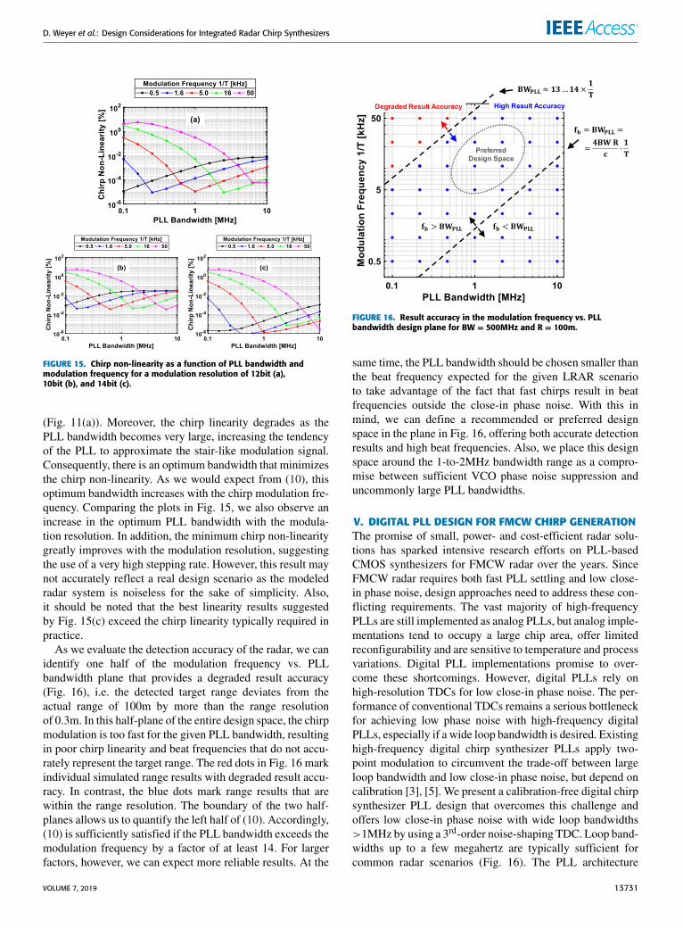
FIGURE 15. Chirp non-linearity as a function of PLL bandwidth andmodulation frequency for a modulation resolution of 12bit (a),10bit (b), and 14bit (c).
(Fig. 11(a)). Moreover, the chirp linearity degrades as thePLL bandwidth becomes very large, increasing the tendencyof the PLL to approximate the stair-like modulation signal.Consequently, there is an optimum bandwidth that minimizesthe chirp non-linearity. As we would expect from (10), thisoptimum bandwidth increases with the chirp modulation fre-quency. Comparing the plots in Fig. 15, we also observe anincrease in the optimum PLL bandwidth with the modula-tion resolution. In addition, the minimum chirp non-linearitygreatly improves with the modulation resolution, suggestingthe use of a very high stepping rate. However, this result maynot accurately reflect a real design scenario as the modeledradar system is noiseless for the sake of simplicity. Also,it should be noted that the best linearity results suggestedby Fig. 15(c) exceed the chirp linearity typically required inpractice.
As we evaluate the detection accuracy of the radar, we canidentify one half of the modulation frequency vs. PLLbandwidth plane that provides a degraded result accuracy(Fig. 16), i.e. the detected target range deviates from theactual range of 100m by more than the range resolutionof 0.3m. In this half-plane of the entire design space, the chirpmodulation is too fast for the given PLL bandwidth, resultingin poor chirp linearity and beat frequencies that do not accu-rately represent the target range. The red dots in Fig. 16 markindividual simulated range results with degraded result accu-racy. In contrast, the blue dots mark range results that arewithin the range resolution. The boundary of the two half-planes allows us to quantify the left half of (10). Accordingly,(10) is sufficiently satisfied if the PLL bandwidth exceeds themodulation frequency by a factor of at least 14. For largerfactors, however, we can expect more reliable results. At the
FIGURE 16. Result accuracy in the modulation frequency vs. PLLbandwidth design plane for BW = 500MHz and R = 100m.
same time, the PLL bandwidth should be chosen smaller thanthe beat frequency expected for the given LRAR scenarioto take advantage of the fact that fast chirps result in beatfrequencies outside the close-in phase noise. With this inmind, we can define a recommended or preferred designspace in the plane in Fig. 16, offering both accurate detectionresults and high beat frequencies. Also, we place this designspace around the 1-to-2MHz bandwidth range as a compro-mise between sufficient VCO phase noise suppression anduncommonly large PLL bandwidths.
V. DIGITAL PLL DESIGN FOR FMCW CHIRP GENERATIONThe promise of small, power- and cost-efficient radar solu-tions has sparked intensive research efforts on PLL-basedCMOS synthesizers for FMCW radar over the years. SinceFMCW radar requires both fast PLL settling and low close-in phase noise, design approaches need to address these con-flicting requirements. The vast majority of high-frequencyPLLs are still implemented as analog PLLs, but analog imple-mentations tend to occupy a large chip area, offer limitedreconfigurability and are sensitive to temperature and processvariations. Digital PLL implementations promise to over-come these shortcomings. However, digital PLLs rely onhigh-resolution TDCs for low close-in phase noise. The per-formance of conventional TDCs remains a serious bottleneckfor achieving low phase noise with high-frequency digitalPLLs, especially if a wide loop bandwidth is desired. Existinghigh-frequency digital chirp synthesizer PLLs apply two-point modulation to circumvent the trade-off between largeloop bandwidth and low close-in phase noise, but depend oncalibration [3], [5]. We present a calibration-free digital chirpsynthesizer PLL design that overcomes this challenge andoffers low close-in phase noise with wide loop bandwidths>1MHz by using a 3rd-order noise-shaping TDC. Loop band-widths up to a few megahertz are typically sufficient forcommon radar scenarios (Fig. 16). The PLL architecture
VOLUME 7, 2019 13731
D. Weyer et al.: Design Considerations for Integrated Radar Chirp Synthesizers
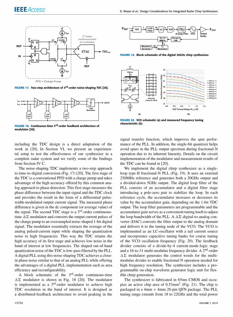
FIGURE 17. Two-step architecture of 3rd-order noise-shaping TDC [20].
FIGURE 18. Continuous-time 3rd-order feedback architecture ofmodulator [20].
including the TDC design is a direct adaptation of thework in [20]. In Section VI, we present an experimen-tal setup to test the effectiveness of our synthesizer in acomplete radar system and we verify some of the findingsfrom Section IV C.
The noise-shaping TDC implements a two-step approachto time-to-digital conversion (Fig. 17) [20]. The first stage ofthe TDC is a conventional PFD with a charge pump and takesadvantage of the high accuracy offered by this common ana-log approach to phase detection. This first stage measures thephase difference between the input signal and the TDC clockand provides the result in the form of a differential pulse-width-modulated output current signal. The measured phasedifference is given in the dc component (or average value) ofthe signal. The second TDC stage is a 3rd-order continuous-time16 modulator and converts the output current pulses ofthe charge pump to an oversampled noise-shaped 1-bit digitalsignal. The modulator essentially extracts the average of theanalog pulsed-current input while shaping the quantizationnoise to high frequencies. This way the TDC retains thehigh accuracy of its first stage and achieves low noise in theband of interest at low frequencies. The shaped out-of-bandquantization noise of the TDC is low-pass filtered by the PLL.A digital PLL using this noise-shaping TDC achieves a close-in phase noise similar to that of an analog PLL while offeringthe advantages of a digital PLL implementation such as areaefficiency and reconfigurability.
A block schematic of the 3rd-order continuous-time16 modulator is shown in Fig. 18 [20]. The modulatoris implemented as a 3rd-order modulator to achieve highTDC resolution in the band of interest. It is designed asa distributed-feedback architecture to avoid peaking in the
FIGURE 19. Block schematic of the digital 20GHz chirp synthesizer.
FIGURE 20. VCO schematic (a) and measured frequency tuningcharacteristic (b).
signal transfer function, which improves the spur perfor-mance of the PLL. In addition, the single-bit quantizer helpsavoid spurs in the PLL output spectrum during fractional-Noperation due to its inherent linearity. Details on the circuitimplementation of the modulator and measurement results ofthe TDC can be found in [20].
We implement the digital chirp synthesizer as a single-loop type-II fractional-N PLL (Fig. 19). It uses an external250MHz reference and generates both a 20GHz output anda divided-down 5GHz output. The digital loop filter of thePLL consists of an accumulator and a digital filter stageintroducing a pole-zero pair to stabilize the loop. In eachreference cycle, the accumulator increases or decreases itsvalue by the accumulator gain, depending on the 1-bit TDCoutput. The loop filter parameters are programmable and theaccumulator gain serves as a convenient tuning knob to adjustthe loop bandwidth of the PLL. A16 digital-to-analog con-verter (DAC) converts the filter output to the analog domainand delivers it to the tuning node of the VCO. The VCO isimplemented as an LC-oscillator with a tail current sourceand incorporates capacitive tuning banks for coarse tuningof the VCO oscillation frequency (Fig. 20). The feedbackdivider consists of a divide-by-4 current-mode-logic stageand a 16-to-31 multi-modulus frequency divider. A 2nd-order16 modulator generates the control words for the multi-modulus divider to enable fractional-N operation needed forhigh frequency resolution. The synthesizer includes a pro-grammable on-chip waveform generator logic unit for flex-ible chirp generation.
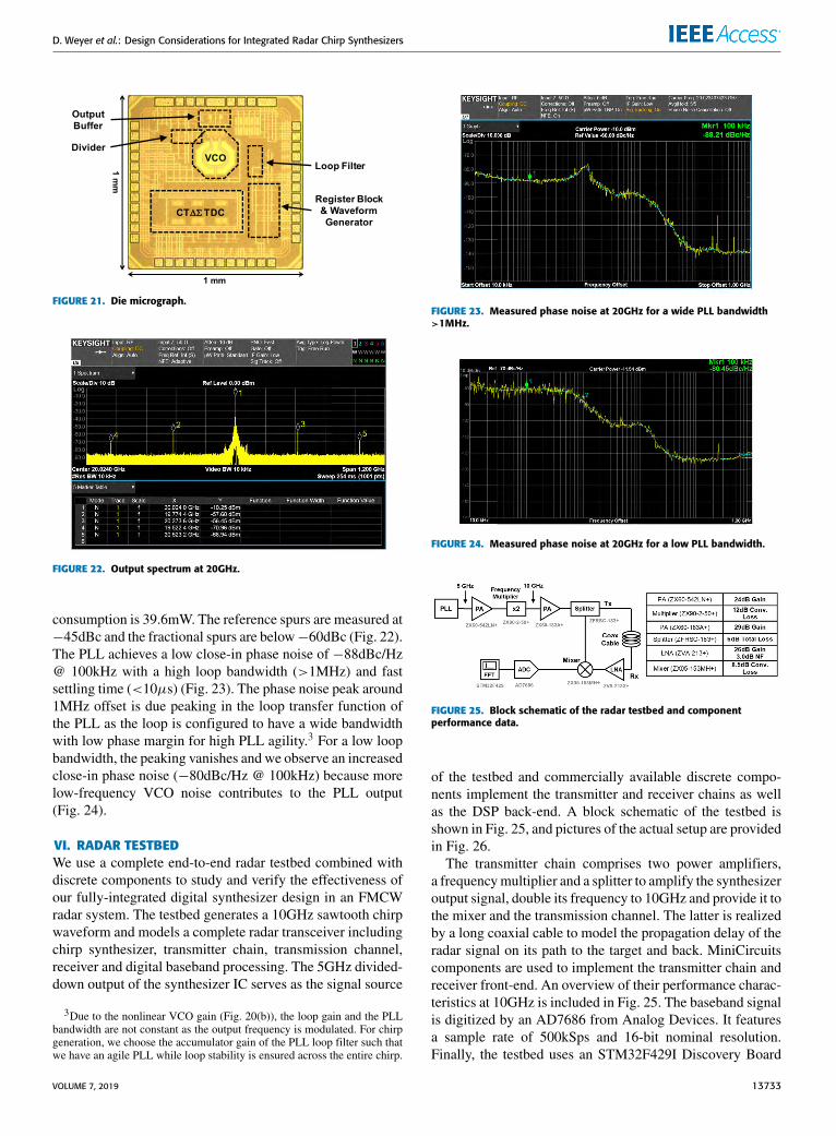
The synthesizer is fabricated in 65nm CMOS and occu-pies an active chip area of 0.53mm2 (Fig. 21). The chip ispackaged in a 4mm × 4mm 28-pin QFN package. The PLLtuning range extends from 18 to 22GHz and the total power
13732 VOLUME 7, 2019
D. Weyer et al.: Design Considerations for Integrated Radar Chirp Synthesizers
FIGURE 21. Die micrograph.
FIGURE 22. Output spectrum at 20GHz.
consumption is 39.6mW. The reference spurs are measured at−45dBc and the fractional spurs are below−60dBc (Fig. 22).The PLL achieves a low close-in phase noise of −88dBc/Hz@ 100kHz with a high loop bandwidth (>1MHz) and fastsettling time (<10µs) (Fig. 23). The phase noise peak around1MHz offset is due peaking in the loop transfer function ofthe PLL as the loop is configured to have a wide bandwidthwith low phase margin for high PLL agility.3 For a low loopbandwidth, the peaking vanishes and we observe an increasedclose-in phase noise (−80dBc/Hz @ 100kHz) because morelow-frequency VCO noise contributes to the PLL output(Fig. 24).
VI. RADAR TESTBEDWe use a complete end-to-end radar testbed combined withdiscrete components to study and verify the effectiveness ofour fully-integrated digital synthesizer design in an FMCWradar system. The testbed generates a 10GHz sawtooth chirpwaveform and models a complete radar transceiver includingchirp synthesizer, transmitter chain, transmission channel,receiver and digital baseband processing. The 5GHz divided-down output of the synthesizer IC serves as the signal source
3Due to the nonlinear VCO gain (Fig. 20(b)), the loop gain and the PLLbandwidth are not constant as the output frequency is modulated. For chirpgeneration, we choose the accumulator gain of the PLL loop filter such thatwe have an agile PLL while loop stability is ensured across the entire chirp.
FIGURE 23. Measured phase noise at 20GHz for a wide PLL bandwidth>1MHz.
FIGURE 24. Measured phase noise at 20GHz for a low PLL bandwidth.
FIGURE 25. Block schematic of the radar testbed and componentperformance data.
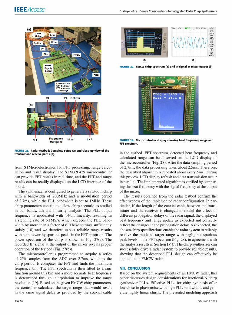
of the testbed and commercially available discrete compo-nents implement the transmitter and receiver chains as wellas the DSP back-end. A block schematic of the testbed isshown in Fig. 25, and pictures of the actual setup are providedin Fig. 26.
The transmitter chain comprises two power amplifiers,a frequencymultiplier and a splitter to amplify the synthesizeroutput signal, double its frequency to 10GHz and provide it tothe mixer and the transmission channel. The latter is realizedby a long coaxial cable to model the propagation delay of theradar signal on its path to the target and back. MiniCircuitscomponents are used to implement the transmitter chain andreceiver front-end. An overview of their performance charac-teristics at 10GHz is included in Fig. 25. The baseband signalis digitized by an AD7686 from Analog Devices. It featuresa sample rate of 500kSps and 16-bit nominal resolution.Finally, the testbed uses an STM32F429I Discovery Board
VOLUME 7, 2019 13733
D. Weyer et al.: Design Considerations for Integrated Radar Chirp Synthesizers
FIGURE 26. Radar testbed: Complete setup (a) and close-up view of thetransmit and receive paths (b).
from STMicroelectronics for FFT processing, range calcu-lation and result display. The STM32F429 microcontrollercan provide FFT results in real-time, and the FFT and rangeresults can be readily displayed on the LCD interface of theboard.
The synthesizer is configured to generate a sawtooth chirpwith a bandwidth of 200MHz and a modulation periodof 2.7ms, while the PLL bandwidth is set to 1MHz. Thesechirp parameters constitute a slow-chirp scenario as studiedin our bandwidth and linearity analysis. The PLL outputfrequency is modulated with 14-bit linearity, resulting ina stepping rate of 6.1MS/s, which exceeds the PLL band-width by more than a factor of 6. These settings sufficientlysatisfy (10) and we therefore expect reliable range resultswith no noteworthy spurious peaks in the FFT spectrum. Thepower spectrum of the chirp is shown in Fig. 27(a). Therecorded IF signal at the output of the mixer reveals properoperation of the testbed (Fig. 27(b)).
The microcontroller is programmed to acquire a seriesof 256 samples from the ADC over 2.7ms, which is thechirp period. It computes the FFT and finds the maximumfrequency bin. The FFT spectrum is then fitted to a sincfunction around this bin and a more accurate beat frequencyis determined through interpolation to improve the rangeresolution [19]. Based on the given FMCW chirp parameters,the controller calculates the target range that would resultin the same signal delay as provided by the coaxial cable
FIGURE 27. FMCW chirp spectrum (a) and IF signal at mixer output (b).
FIGURE 28. Microcontroller display showing beat frequency, range andFFT spectrum.
in the testbed. FFT spectrum, detected beat frequency andcalculated range can be observed on the LCD display ofthe microcontroller (Fig. 28). After the data sampling periodof 2.7ms, the data processing takes about 2.5ms. Therefore,the described algorithm is repeated about every 5ms. Duringthis process, LCD display refresh and data transmission occurin parallel. The implemented algorithm is verified by compar-ing the beat frequency with the signal frequency at the outputof the mixer.
The results obtained from the radar testbed confirm theeffectiveness of the implemented radar configuration. In par-ticular, if the length of the coaxial cable between the trans-mitter and the receiver is changed to model the effect ofdifferent propagation delays of the radar signal, the displayedbeat frequency and range update as expected and correctlyreflect the changes in the propagation delay. As expected, thechosen chirp specifications enable the radar system to reliablyresolve the modeled target range with negligible spuriouspeak levels in the FFT spectrum (Fig. 28), in agreement withthe analysis results in Section IVC . The chirp synthesizer cansuccessfully drive a radar system to provide reliable results,showing that the described PLL design can effectively beapplied in an FMCW radar.
VII. CONCLUSIONBased on the system requirements of an FMCW radar, thispaper discusses design considerations for fractional-N chirpsynthesizer PLLs. Effective PLLs for chirp synthesis offerlow close-in phase noise with high PLL bandwidths and gen-erate highly linear chirps. The presented modeling approach
13734 VOLUME 7, 2019
D. Weyer et al.: Design Considerations for Integrated Radar Chirp Synthesizers
allows for a straightforward study of the impact of the PLLbandwidth on the accuracy and reliability of target detection.Our analysis for a long-range automotive radar scenario con-siders both slow and fast chirp modulation. We show thatan optimum PLL bandwidth falls below the chirp steppingrate by a factor of at least 3, and it exceeds the modulationfrequency by a factor of at least 14. Moreover, a digital chirpsynthesizer PLL that uses a noise-shaping TDC and meetsthe requirements of FMCW radar is presented. Experimentalresults of a complete end-to-end radar testbed confirm thatthe synthesizer can effectively drive an FMCW radar system.
REFERENCES[1] J. Hatch, A. Topak, R. Schnabel, T. Zwick, R.Weigel, and C.Waldschmidt,
‘‘Millimeter-wave technology for automotive radar sensors in the 77 GHzfrequency band,’’ IEEE Trans. Microw. Theory Techn., vol. 60, no. 3,pp. 845–860, Mar. 2012.
[2] A. G. Stove, ‘‘Linear FMCW radar techniques,’’ IEE Proc. F-Radar SignalProcess., vol. 139, no. 5, pp. 343–350, Oct. 1992.
[3] D. Cherniak, L. Grimaldi, L. Bertulessi, C. Samori, R. Nonis, andS. Levantino, ‘‘A 23-GHz low-phase-noise digital bang–bang PLL for fasttriangular and sawtooth chirp modulation,’’ in IEEE ISSCC Dig. Tech.Papers, Feb. 2018, pp. 248–250.
[4] J. Vovnoboy, R. Levinger, N. Mazor, and D. Elad, ‘‘A fully integrated75–83 GHz FMCW synthesizer for automotive radar applications with -97 dBc/Hz phase noise at 1 MHz offset and 100 GHz/mSec maximal chirprate,’’ in Proc. IEEE Radio Freq. Integr. Circuits Symp. (RFIC), Jun. 2017,pp. 96–99.
[5] W. Wu, R. B. Staszewski, and J. R. Long, ‘‘A 56.4-to-63.4 GHz multi-rate all-digital fractional-N PLL for FMCW radar applications in 65 nmCMOS,’’ IEEE J. Solid-State Circuits, vol. 49, no. 5, pp. 1081–1096,May 2014.
[6] B. P. Ginsburg et al., ‘A multimode 76-to-81GHz automotive radartransceiver with autonomous monitoring,’’ in IEEE ISSCC Dig. Tech.Papers, Feb. 2018, pp. 158–160.
[7] J. Lee, Y.-A. Li, M.-H. Hung, and S.-J. Huang, ‘‘A fully-integrated 77-GHzFMCW radar transceiver in 65-nm CMOS technology,’’ IEEE J. Solid-State Circuits, vol. 45, no. 12, pp. 2746–2756, Dec. 2010.
[8] T. Mitomo, N. Ono, H. Hoshino, Y. Yoshihara, O. Watanabe, and I. Seto,‘‘A 77GHz 90 nmCMOS transceiver for FMCWradar applications,’’ IEEEJ. Solid-State Circuits, vol. 45, no. 4, pp. 928–937, Apr. 2010.
[9] S. O. Piper, ‘‘FMCW linearizer bandwidth requirements,’’ in Proc. IEEENat. Radar Conf., Mar. 1991, pp. 142–146.
[10] S. O. Piper, ‘‘Homodyne FMCW radar range resolution effects with sinu-soidal nonlinearities in the frequency sweep,’’ in Proc. Int. Radar Conf.,1995, pp. 563–567.
[11] M. I. Skolnik, Introduction to Radar Systems, 3rd ed. Boston, MA, USA:McGraw-Hill, 2002.
[12] F. M. Gardner, Phaselock Techniques. Hoboken, NJ, USA: Wiley, 1966.[13] T. A. D. Riley, M. A. Copeland, and T. A. Kwasniewski, ‘‘Delta-sigma
modulation in fractional-N frequency synthesis,’’ IEEE J. Solid-State Cir-cuits, vol. 28, no. 5, pp. 553–559, May 1993.
[14] E. Laskin et al., ‘‘Nanoscale CMOS transceiver design in the 90–170-GHz range,’’ IEEE Trans. Microw. Theory Techn., vol. 57, no. 12,pp. 3477–3490, Dec. 2009.
[15] M. C. Budge andM. P. Burt, ‘‘Range correlation effects in radars,’’ in Proc.Rec. IEEE Nat. Radar Conf., Apr. 1993, pp. 212–216.
[16] K. Thurn, R. Ebelt, and M. Vossiek, ‘‘Noise in homodyne FMCW radarsystems and its effects on ranging precision,’’ in IEEE MTT-S Int. Microw.Symp. Dig., Jun. 2013, pp. 1–3.
[17] A. Ergintav, F. Herzel, D. Kissinger, and H. J. Ng, ‘‘An investigation ofphase noise of a fractional-N PLL in the course of FMCW chirp genera-tion,’’ in Proc. IEEE Int. Symp. Circuits Syst. (ISCAS), May 2018, pp. 1–4.
[18] M. Gerstmair, A. Melzer, A. Onic, R. Stuhlberger, and M. Huemer,‘‘Highly efficient environment for FMCW radar phase noise simulationsin IF domain,’’ IEEE Trans. Circuits Syst. II, Exp. Briefs, vol. 65, no. 5,pp. 582–586, May 2018.
[19] H.-H. Ko, K.-W. Cheng, and H.-J. Su, ‘‘Range resolution improvement forFMCW radars,’’ in Proc. Eur. Radar Conf., 2008, pp. 352–355.
[20] M. B. Dayanik, N. Collins, and M. P. Flynn, ‘‘A 28.5–33.5GHz fractional-N PLL using a 3rd order noise shaping time-to-digital converter with176fs resolution,’’ in Proc. Conf. 41st Eur. Solid-State Circuits Conf.(ESSCIRC), Sep. 2015, pp. 376–379.
DANIEL WEYER received the B.Sc. and Diplomdegrees in electrical engineering and informa-tion technology from the Technical University ofMunich, Munich, Germany, in 2010 and 2013,respectively, theM.S. degree in electrical and com-puter engineering from the Georgia Institute ofTechnology, Atlanta, GA, USA, in 2012, and thePh.D. degree in electrical engineering from theUniversity of Michigan, Ann Arbor, MI, USA,in 2018.
He is currently with Silicon Laboratories Inc., Austin, TX, USA. Hisresearch interests include mixed-signal, RF, and mm-wave IC design, fre-quency synthesizers, and noise-shaping data converters.
MEHMET BATUHAN DAYANIK was born inKarabuk, Turkey. He received the B.Sc. and M.Sc.degrees from Middle East Technical University,Ankara, Turkey, in 2005 and 2007, respectively,and the Ph.D. degree from the University ofMichi-gan, Ann Arbor, MI, USA, in 2017. From 2007 to2012, he was with Hittite Microwave Corporation,Istanbul, Turkey.
He is currently with Broadcom Ltd., Irvine, CA,USA, as a Design Engineer, where he is involved
in high-speed serial links. His research interests include high-frequencyfractional-N PLLs and high-speed ADCs.
LU JIE was born in Guangzhou, China, in 1995.He received the B.Eng. degree in electrical andelectronic engineering from Zhejiang Univer-sity, China, in 2017. He is currently pursu-ing the Ph.D. degree in electrical engineeringwith the University of Michigan, Ann Arbor,MI, USA.
His research interests includemixed-architectureADCs and high-speed serial interfaces.
AHMED ALBALAWI received the B.S. degreein electrical engineering from Taibah University,Madinah, Saudi Arabia, in 2011. He is cur-rently pursuing the M.S. degree with the Uni-versity of Michigan, Ann Arbor, MI, USA. Hejoined King Abdulaziz City for Science and Tech-nology, Riyadh, Saudi Arabia, in 2012, wherehe was involved in various projects, includingpulsed frequency-modulated continuous wave andmillimeter-wave radar systems. His research inter-
ests include the sub-millimeter wave and terahertz-integrated circuits.
VOLUME 7, 2019 13735
D. Weyer et al.: Design Considerations for Integrated Radar Chirp Synthesizers
ABDULHAMED ALOTHAIMEN received theB.S. degree (Hons.) in electrical engineering fromKing Saud University, Riyadh, Saudi Arabia,in 2015. He is currently a Researcher with theNational Center for Radar and Electronic WarfareTechnologies, King Abdulaziz City for Scienceand Technology (KACST). He is also a Researcherwith the joint Center of Excellence for MicrowaveSensor Technology between KACST and the Uni-versity of Michigan. He was previously an Elec-
tronics Engineer with the Prince Sultan Advanced Technology ResearchInstitute.
MOHAMMED ASEERI received the bachelor’sdegree in electrical engineering and computerengineering and the M.Sc. degree in electricalengineering and computer engineering, with aspecialization in electronics and communications,from King Abdulaziz University, and the Ph.D.degree in electronics from the University of Kent,Canterbury, U.K. He is currently an Associate Pro-fessor with the National Centre for Radar and EWTechnologies, King Abdulaziz City for Science
and Technology (KACST), and also a Researcher with the joint Center ofExcellence for Microwave Sensor Technology between KACST and theUniversity ofMichigan. Also, he has an authorized certificate as a ConsultantEngineer from the Saudi Council of Engineers. He was the Head of theMaritimes Studies Section, Ministry of Interior, Border Guard, Saudi Ara-bia. His previous experiences include the Project’s Manager of ElectronicSurveillance Systems and the Director of Draft Regulations for ElectronicSurveillance Systems, SOS International GMDSS as well as the supervisionof several programs and projects of sensitive surveillance systems at theInterior Ministry Border Guards, as he holds PMP certification. He hasalso written and authored several papers on field programmable gate array,digital security as well as wireless sensor networks, security networks, E-strategic management, and secure planning. He was a Researcher in differentinternational universities, such as the University of Canberra, Australia, andTheAustralian National University, Australia. He has publishedmany papersin high-level journals and conferences. He is a member of the IEEE and theInstitute of Engineering and Technology.
MICHAEL P. FLYNN received the Ph.D. degreefrom Carnegie Mellon University, Pittsburgh, PA,USA, in 1995. From 1995 to 1997, he was a Mem-ber of Technical Staff with Texas Instruments,Dallas, TX, USA. From 1997 to 2001, he was withParthus Technologies, Cork, Ireland. He joined theUniversity of Michigan, in 2001, where he is cur-rently a Professor. His technical interests includeRF circuits, data conversion, serial transceivers,and biomedical systems.
Dr. Flynn is a 2008 Guggenheim Fellow. He received the 2016 Universityof Michigan Faculty Achievement Award, the 2011 Education ExcellenceAward, the 2010 College of Engineering Ted Kennedy Family Team Excel-lence Award from the College of Engineering, University of Michigan,the 2005–2006 Outstanding Achievement Award from the Department ofElectrical Engineering and Computer Science, University of Michigan, andthe NSF Early Career Award, in 2004.
Dr. Flynn was the Editor-in-Chief of the IEEE JOURNAL OF SOLID-STATE
CIRCUITS, from 2013 to 2016. He is a former Distinguished Lecturer of theIEEE Solid-State Circuits Society. He serves on the Technical ProgramCom-mittee of the European Solid-State Circuits Conference. He is the Chairof the Data Conversion Committee of the International Solid-State CircuitsConference. He formerly served on the Technical ProgramCommittees of theAsian Solid-State Circuits Conference and the Symposium onVLSI Circuits.He served as anAssociate Editor of the IEEE JOURNALOF SOLID-STATECIRCUITS
and the IEEE TRANSACTIONS ON CIRCUITS AND SYSTEMS.
13736 VOLUME 7, 2019