Embed Size (px)
Citation preview

DESIGN, CONSTRUCTION AND DISTRUBUTED CONTROL OF HIGH DEGREE OF
FREEDOM MODULAR ROBOT
APPROVED BY SUPERVISING COMMITTEE:
Mo Jamshidi, Ph.D., Chair
Jeff Prevost, Ph.D.
Ahmed Taha, Ph.D.
Accepted:Dean, Graduate School


DEDICATION
This thesis is dedicated to my dear family and friends. Thank you for providing me with constantinspiration, encouragement and support.

DESIGN, CONSTRUCTION AND DISTRUBUTED CONTROL OF HIGH DEGREE OF
FREEDOM MODULAR ROBOT
By
IKRAM HUSSAINMOHAMMED, B.E.
THESISPresented to the Graduate Faculty of
The University of Texas at San Antonioin Partial Fulfillmentof the Requirements
for the Degree of
MASTER OF SCIENCE IN ELECTRICAL ENGINEERING
THE UNIVERSITY OF TEXAS AT SAN ANTONIOCollege of Engineering
Department of Electrical and Computer EngineeringAugust 2016

iii
ACKNOWLEDGEMENTS
I would like to express my gratitude to my supervisor Dr. Mo Jamshidi for his
support, his major help and directions during my master study and research. I would like to
thank Dr. Jeff Prevost and Dr. Ahamed Taha for being members of my thesis committee,
giving suggestions and productive comments. Also I would to thank Ben Champion and Dr.
Patrick Benavidez and for his invaluable support and guidance, it would have been difficult
to reach this point without his help. I am thankful to Berat Erol, Nicolas Gallardo, Ibrahim
Mohammed, Abhijith Puthussery and the entire team of Autonomous Control Engineering
laboratory for their support and collaboration. I would also like to thanks Air Force
Research Laboratory and OSD through a contract with North Carolina Agricultural and
Technical State University (Grant number FA8750-15-2-0116) for supporting this work.
Finally, I would like to express my sincere gratitude to my family for their
encouragement and support.
August 2016

DESIGN, CONSTRUCTION AND DISTRIBUTED CONTROL OF HIGH DEGREE OF
FREEDOM MODULAR ROBOT
Ikram Hussain Mohammed, M.S.The University of Texas at San Antonio, 2014
Supervising Professor: Mo Jamshidi, Ph.D.
The ability for a robot to navigate different terrains is a big problem in the field of robotics.
Designing and constructing a robot that is able to traverse a single type of terrain such as grassy
fields, indoors, in the air and even under the water is a widely tackled problem and many different
and viable solutions have been discovered and implemented. This issue becomes highly
complicated when multiple non-uniform and potentially unstable terrains are to be traversed by a
single robot, such as a collapsed building. A potential solution to this problem is presented within
this thesis, this being a snake robot.
The design, construction and distributed control of a 3D printed snake robot is presented;
with the modular design being focused on allowing for the fast and low cost generation and
implementation of the robotic snake. This robot has been designed to complete a wide variety of
tasks and motions such as serpentine motion, square-wave motion, mamba position as well as
incorporating a climbing ability, all in which keep in check with the merits and demerits of the
other snake robots. The square wave and climbing motion of the snake robot have been
accomplished by utilizing a friction based push-pull method, thoroughly discussed within. In order
to achieve smooth serpentine motion, a passive wheel adapter was fitted onto several of the
modules to enable a more controlled motion. An approach is also investigated which allows the
snake robot to be attached to the end of a serial manipulator robot to increase its prevailing degrees
of freedom. The mechanical designing of the robot was achieved using the SolidWorks platform,
allowing the prototyping the design to be carried out with 3D printing.

The control of the robot is based off Central Pattern Generators (CPG), a form of disturbed
control. In accordance with the concept of CPG, an adaptable control architecture was developed
so many forms of movement could be integrated into a single design. Robot Operating System
(ROS) was used as an underlying architecture for the robot, allowing for the robot to have an
adaptable design which could be easily modified according to the required application. A detailed
description of the design, construction, control and testing of the snake robot is presented within
this thesis.
TABLE OF CONTENTS
Acknowledgements ........................................................................................................................ iii
Abstract ........................................................................................................................................... iv
List of Tables ................................................................................................................................. ix
List of Figures ............................................................................................................................... x
Chapter 1: Introduction ......................................................................................................................1
Chapter 2: A study of snake-inspired robot designs..........……….………….....................................4
2.1. Designs of Snake Robot……...…………………………...………………………...………4
2.1.1. Active bending joint and passive wheel type................................................................5
2.1.2. Active bending and elongating joint type..................................................................... 7
2.1.3. Active bending joint and active wheel type.……………...…………………………..8
2.1.4. Passive bending joint and active wheel type............................................................….8
2.1.5. Active bending joint and active crawler type................................................................9
2.1.6. Robots based on undulation using vertical waves.……………………...………...…11
2.1.7. Active joint with fixed base type...…………………………………...……………...12
2.2 Currently Implemented Snake Robot and Proposed Approch.……………………..………13
2.2.1. Currently Implemented Snake Robot...……………………………………………...13
2.2.2 Conclusion for the study …………………………………………………………….15
Chapter 3: Locomotion, Distributed control and control of snake .............................................................16
3.1 Locomotion………………………………………………………………………………....16
3.1.1. Lateral Undulation or Serpentine Motion...................................................................16
3.1.2. Linear Progression................................................................................................................17
3.1.3 Concertina Locomotion.……………………………………………………………...17
3.1.4. Sidewinding Locomotion........................................…………………………….……..18
3.1.5. Climbing Locomotion...........................................................................................…...19

3.2 Distributed Control and Control of Snake Robots.…………………………………………20
3.2.1 Control of Snake Robots..............................................................................................20
3.2.2. Distributed Control......................................................................…………………….23
Chapter 4: Mechanical Design and Construction of Modular Robot....................................................26
4.1 Design of Segment Module………………………………………………………………...26
4.2 Housing……………………………………………………………………………………..28
4.3 Passive Wheel Adaptor……………………………………………………………………..29
4.4 Actuation …………………………………………………………………………………..30
4.5 3D Printing…………………………………………………………………………………31
4.6 Implementation and Construction of design in 3D Printer…………………………………33
4.7 Cost…………………………………………………………………………………………35
Chapter 5: Electrical Design of Modular Robot……………………………………………...........37
5.1 Control Architecture ..............................................……………………………………..….37
5.2 Processing Unit. ..............................................……………………………………………..38
5.3. Communication.......................................... …………………………….............................38
5.4. Head ............................................................... ……………………………........................41
5.5. Body.......................................................... ………………………………………………..41
5.6. Tail .......................................................................................................................................42
5.7. Power Source and Distribution ............................................................................................42
5.7.1 Tether……………………………………………………………………………………...42
5.7.2 Battery…………….………………………………………………………………………43
5.7.3 Battery Selection and Schematic Diagram……………….…………………………………45
Chapter 6: Control Algorithm...........................................................................................................47
6.1. Square wave Motion Algorithm…………............................................................................47
6.2. Pole Climbing Algorithm.....................................................................................................50
6.3. Standing Cobra position for surveillance .............................................................................53
6.4. Sine wave motion with passive wheel…………………………………………………………….54
Chapter 7: Experimental Results......................................................................................................57
7.1. Testing Microcomputer and Communication............... ......................................................57
7.2. Testing Servos and controlling its positon...................................... ................. ..................58
7.3 Snake Robot in standing Cobra position................ ................ ................ ........... ................59
7.4 Square wave motion of snake robot................ ................ ................ .................. ................60
7.5 climbing of snake robot................ ................ ................ ................ .................... ................60
Chapter Eight: Conclusion and Future Work .................................................................................. 62
References.........................................................................................................................................65

ix
LIST OF TABLES
Table 1 Cost for implementation of design..........................................................................36

LIST OF FIGURES
Figure 1: The world’s first snake robot - ACM III [7].................................................................... 4
Figure 2: Active bending joint and passive wheel type robots [8] ................................................. 5
Figure 3: ACM-R5 Snake robot [11] .............................................................................................. 6
Figure 4: Slim Slime Robot [13]..................................................................................................... 7
Figure 5: ACM-R4 Active bending joint and active wheel type [14]............................................. 8
Figure 6: Genbu - Passive bending joint and active wheel type robot [9] ...................................... 9
Figure 7: Active bending joint and active crawler type robot [17]............................................... 10
Figure 8: CMU Modular Snake Robot [18].................................................................................. 11
Figure 9: Snake arm robot by OC robotics [20] ........................................................................... 12
Figure 10: Lateral undulation [18] ................................................................................................ 16
Figure 11: Linear Progression [27] ............................................................................................... 17
Figure 12: Concertina locomotion [61]......................................................................................... 18
Figure 13: Sidewinding locomotion [62] ...................................................................................... 19
Figure 14: Climbing locomotion [63] ........................................................................................... 20
Figure 15: CPG Oscillator [34]..................................................................................................... 22
Figure 16: Functional levels of a typical Distributed Control System [39] .................................. 24
Figure 17: DCS of Snake-like Robot ............................................................................................ 25
Figure 18: Components of 3D Printed Modular Robot [2]........................................................... 27
Figure 19: Front Housing.............................................................................................................. 28
Figure 20: Rear housing................................................................................................................ 29
Figure 21: Passive Wheel Adapter [2] .......................................................................................... 30

xi
Figure 22: CAD Model of snake robot [2].................................................................................... 33
Figure 23: 3D printed modular snake robot [2] ............................................................................ 33
Figure 24: Rubber skin attached to the robot................................................................................ 34
Figure 25: Snake robot with Passive Wheel Adapter ................................................................... 34
Figure 26: Snake robot used as End Effector [2] .......................................................................... 35
Figure 27: Control Architecture Block Diagram [2]..................................................................... 37
Figure 28: Tether connection diagram.......................................................................................... 43
Figure 29: Schematic diagram of battery connection ................................................................... 45
Figure 30: CAD Model of Square Wave ...................................................................................... 48
Figure 31: Friction distribution of Square Wave Motion ............................................................. 48
Figure 32: Control Algorithm for Square Wave ........................................................................... 49
Figure 33: CAD Model of Robot Climbing.................................................................................. 51
Figure 34: Control Algorithm for Climbing ................................................................................. 52
Figure 35: CAD model of Standing Cobra Position ..................................................................... 53
Figure 36: Forward Motion generated by Passive Wheel............................................................. 55
Figure 37: Left and Right turning using Sine Wave ..................................................................... 55
Figure 38: Sine Wave Motion with Passive Wheel Adapter ........................................................ 56
Figure 39: Data Feedback Communication .................................................................................. 58
Figure 40: Position and Load Feedback........................................................................................ 59
Figure 41: Cobra Position for surveillance ................................................................................... 60
Figure 42: Square Wave Locomotion [2] ..................................................................................... 60
Figure 43: Pole Climbing.............................................................................................................. 61

CHAPTER 1
INTRODUCTION
Robotics constitutes of a wide variety of technologies that in which computational
intelligence is incorporated in physical machines. This led to the creations of systems with
capabilities far exceeding the core components alone, which could achieve potentially tasks that
are unachievable by conventional tools and/or humans [1]. Robots has broad applications in
various fields. It could be used in transit to places that are hazardous or unreachable to humans.
In contrast, the mundane tasks in different fields could also be achieved, such as in agriculture,
healthcare, environmental monitoring, education, or in personal service [1]. But depending on
their market requirements, they are usually categorized as industrial robots and service robots
[1]. Also, based on the terrain that they maneuver, they are improved and modified. When robots
that operate on the land are considered, they can be categorized generally as tracked or wheeled
robots. There are many challenges associated with these types of robots, that they are unsuitable
for navigating through unstable terrain such as in a collapsed building or when navigating in
tight/confined spaces such as the inside of a pipe [2]. To overcome these challenges, a high
degree of freedom modular robot have been developed commonly known as snake robots.
Snake robots use their many internal degrees of freedom (DOF) to thread through tightly
packed spaces, allowing the robot to have access to locations where people or machinery cannot
reach [3]. These robots can coordinate their internal DOF to perform a variety of movements
like crawling, climbing and swimming, making it suitable for number of applications such as
search and rescue in disaster site, inspection of narrow and unstructured environments like
collapsed buildings and even in reconnaissance situations [4]. Furthermore, when an operation

2
which requires a number of different obstacles to overcome, the locomotive adaptability of snake
robots makes them great applicants. For instance, if a robot need to perform a task to carry a
camera to the top of a tree which is located and growing in water, then three steps have to be
performed in order to complete the task: move over ground to the water's edge, swim to the tree,
and then climb the tree. One could make a robot that specializes in only one of those three tasks
easily, but being able to do all three, and many other difficult combinations of tasks, is what
makes snake robots exceptional [5]. A snake robot can also be used as end effector of a
manipulator to increase the number of DOF of the robot.
This research work presents a high degree of freedom (DOF) modular robot or snake
robot that combines the strengths of the current state-of-the-art designs with required innovations
which are discussed in upcoming section. A modular robot has been developed to achieve
complicated tasks such as: climbing, smooth serpentine motion, and increase an ABB Industrial
Manipulator robot's DOF.
The Thesis is organized as follows. Chapter 2 presents a literature review on the existing
and the current state of art snake robot, focusing on the design of different types of snake robots
that have been constructed. The different type of locomotion, distributed control and control of
the snake robot is discussed in Chapter 3. The mechanical design, construction and
implementation of the design through 3D printing is presented in Chapter 4. In addition, the
designing of both the modules for the snake as well as the construction of different add-ons
required for different application is focused, and 3D printing as a fast manufacturing process is
also discussed in order to demonstrate how this method of construction is ideal for prototyping
this type of robot. In Chapter 5, the main focus is the electrical design of the robot, where the

3
many subsystems of the robot are presented, such as the power distribution system used, as well
as the various sensors and the microcomputer that enables both local control and sensor
processing. In Chapter 6, the control algorithm for serpentine motion, square wave motion,
standing cobra position for surveillance and climbing up a cylindrical poll has been presented.
The experimental results of the robot where all the testing of various components of the robot
such as the microcomputer, servo, communication and execution of different that are explained
in previous section are discussed in Chapter 7. Finally, conclusion and future work with regard to
this type of snake robot are described in Chapter 8.

4
CHAPTER 2
A STUDY OF SNAKE-INSPIRED ROBOT DESIGNS
2.1 Design of Snake Robots
Snake robot consists of a large number of actuated links connected together in series called
hyper-redundant mechanism [6]. Due to the high degrees of freedom in snake robots, they are
able to navigate in a wide range environments. Shigeo Hirose is known as the founder of snake
robotics. He was the first person to create a robot that employed the serpentine motion which is
commonly found in real snakes. Figure 1 shows the snake robot ACM III, the first snake robot
developed by Shigeo Hirose in 1972 [7]. In this section, a study based on mechanical design
snake robot is reviewed.
Figure 1: The world’s first snake robot - ACM III [7]

5
2.1.1 Active Bending Joint and Passive Wheel Type
These robot types consist of serially connected active bending joints, and is equipped with
passive wheels to reduce the ground friction, thereby enabling forward locomotion on flat
surfaces. It is the most standard form of a snake robot. The example of these robots are ACM-
III, ACM-R3 and ACM-R5 which are illustrated in Figure 2.
Figure 2: Active bending joint and passive wheel type robots [8]
ACM-R5, which stands for Active Cord Mechanism – R5, is an amphibious snake-like robot.
This robot is the result of series of development by robot from ACM-1 to ACM-R4 and is one of
the most advanced in the ACM snake robot family created by Hirose and Yamada [9]. It lies
under the classification of active bending joint with passive wheel type. It is constructed and
characterized by dust- and water-proof body structure. A similar model named HELIX with
helical swimming motion [10] was built in 2002, and ACM-R5 is the modified model of
HELIX. Figure 3 shows the ACM-R5 snake robot.
In order to realize the hermetic structure, a universal joint mechanism driven by a pair of
geared motors from both ends is introduced. The external parts of these universal joint
mechanisms are sealed by flexible bellows and an aluminum outer shell. The number of

6
connecting joints can be modified. This robot is composed of eight joints, which is 1.6 m in
length and weighs 6.5 kg [8]. Figure 3(a) shows mechanical design of ACM-R5’s body module.
The pitch motor and yaw motor are present at the left and right side of the joint. The joint design
is illustrated in Figure 3(b) and Figure 3(c) [11] [12]. This is composed of motor and reduction
gears that drive the universal joints, along with the bellows and outer shell to cover them. This
robot is designed in such a way that the universal joint cannot transmit constant-velocity rotation
when the connecting shaft is not coaxial or is inclined [8]. However, there is a discrepancy
between these transmission mechanisms as the bellows that cover the universal joint can transmit
constant-velocity rotation regardless of the angle of the connecting shaft. To resolve this
problem, a passive rolling axis at the connecting member of the center of the universal joint was
introduced. Motor joints are designed to be connected with a polyacetal tube, and an O-ring
fitted in the tube’s groove keeps out water. Underwater swimming fins are attached around the
outer circumference of the ACM-R5, and passive wheels are also attached to the tip of each fin
to allow creeping motion on the ground.
Figure 3: ACM-R5 Snake robot [11]

7
2.1.2 Active Bending and Elongating Joint Type
When the snake robot is given freedom to elongate itself, the robot can exhibit motion like
that of a worm. This motion makes it possible to have forward movement while maintaining a
straight body form, so that the robot can move through a straight pipe where creeping motion is
impossible to perform.
Figure 4: Slim Slime Robot [13]
The slim slime robot [13] comes under this category; it is made up of linearly connecting
multiple modules that pneumatically bend and elongate. Inside a module as shown in Figure 4, it
has three bellows which are arranged equally round the circumference at an angle with respect to
the axis of each module and sandwiched between disks [13]. These bellows expand when
compressed air is supplied, and they shrink when the air is drained out. Both ends of each
bellows are fixed with two disks, and the disks are connected to each other by expanding springs.
Each bellow has two solenoid valves embedded, used for the intake and removal of the

8
compressed air. The module bends and elongates by controlling the compressed air that is
supplied to the three bellows [8] [13].
2.1.3 Active Bending Joint and Active Wheel Type
In this type of snake robot they have both serially connected active bending joints and
active wheels which are driven by motors. The ACM-R4 snake like robot is an example of this
type. It has both active joints and active wheels, and it consists of nine joint sections, and two
active wheels in each section which is driven by a single motor [14]. The active wheels are
attached in a way without interfering with the joint rotation around the axes. Inside each joint,
the motors that drive the joint and the wheels are housed as shown in Figure 5. To provide space
inside, a four point contact bearing with a large diameter is used for the joint’s rotation axis, and
the joint is driven by internal gears. It is made from a rubber ring between the internal gears on
the final stage of the drive system and the joint frame [8]. This robot has a great ability to go
over obstacles when compared with other type of robots with passive wheels [14].
Figure 5: ACM-R4 Active bending joint and active wheel type [14]
2.1.4 Passive Bending Joint and Active Wheel Type
This category of snake robot has motor driven wheels but has serially connected passive
bending joints. The ‘Genbu’ robot (Figure 6) is classified under this group of the robot. It is

9
characterized by a structure that has a number of large-diameter active wheels attached to the
body connected by passive rubber joints. All the wheels are independently driven, and the
propulsive force of each wheel is transmitted through the elastically joined body [15].
Navigation can be done correctly by regulating the propulsive forces produced by the wheels so
as to change the direction of the whole body. The body can inactively adjust to harsh landscape,
so that any redundant force does not disturb the body even when it’s moving at higher velocity.
This gives the body a high degree of toughness and durability. But the robot cannot be navigated
if large gap exists or the terrain is markedly uneven in the environment.
Figure 6: Genbu - Passive bending joint and active wheel type robot [9]
2.1.5 Active Bending Joint and Active Crawler Type
The characteristic of a snake-like robot is its slender and long body with active joints, in
which each segment is covered with crawlers so that the propulsive force can be transmitted no
matter how the crawlers come in contact with the rubble. The joints connecting the segments can
be bent in two directions by a pair of prismatic links [16]. The model for this type of robot are
“OmniThread” snake robot and “Souryu” (Figure 7). The first Souryu robot design was

10
developed by Hirose to explore the possibility of a functional ACM being used in restricted
spaces [3]. The characteristic of this robot is its slender and long body with active joints, it is
composed of three segments, with crawlers connected with bending joints. The bending joint is
composed of a pair of parallel link mechanisms that are driven by slide screws. The right-handed
screw and left-handed screw are set on both ends of the slide screw’s shaft, so that the robot can
perform a symmetrical bending motion at the anterior or posterior connection parts
simultaneously [8] [17].
Figure 7: Active bending joint and active crawler type robot [17]
OmniThread robot is much more powerful than Souryu as it is consisted of five segments that are
connected by four 2-DOF joints. The thrust of the robot is achieved by using tank treads on the
four sides of every link. The tank tread design maximized the “propulsion ratio”, the ratio of
surface area that was active in propulsion to the surface area that was not. In order to maximize
this ratio, tank treads covered as much of the sides as possible and the gap size between the links
were minimized. The idea behind the maximization of this ratio was that any environmental

11
feature that contacts the robot at a location not covered by the treads would not impede the
motion. Treads on each side also made the design indifferent to falling over [17].
2.1.6 Robots based on Undulation using Vertical Waves
This type of robot consists of active bending joints and does not have passive wheels on it.
It use its multiple degree of freedom to move. The PolyBot reconfigurable robot and the CMU
Modular snake robot (Figure 8) comes under this category.
Figure 8: CMU Modular Snake Robot [18]
The CMU’s modular snake robot is one the most efficient robot. This modular robots exhibits
several snake-inspired gaits for achieving difficult tasks such as climbing, swimming and
crossing gaps. Each module consists of a single servomotor, which created half of the structure
of the module and provides the torque to move and maintains angles while resisting forces from
the environment. To complete the other half of the joint, a U case is attached to the output arm.
The U case has one end connected to the output of the servo and the other to the back of the
servo. Moreover, the robots also utilizes modifications to their outer surface to improve
performance in a number of environments. These modifications takes the form of a full, possibly
12
sealed, covering called skin or the adherence of additional material to the modules themselves,
called compliance. The compliance material may serve to increase the coefficient of friction
between the robot and the surface in order to better simulate the function of a snake's scales in
contact with the terrain [19].
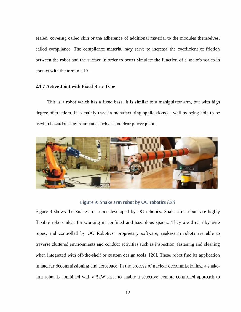
2.1.7 Active Joint with Fixed Base Type
This is a robot which has a fixed base. It is similar to a manipulator arm, but with high
degree of freedom. It is mainly used in manufacturing applications as well as being able to be
used in hazardous environments, such as a nuclear power plant.
Figure 9: Snake arm robot by OC robotics [20]
Figure 9 shows the Snake-arm robot developed by OC robotics. Snake-arm robots are highly
flexible robots ideal for working in confined and hazardous spaces. They are driven by wire
ropes, and controlled by OC Robotics’ proprietary software, snake-arm robots are able to
traverse cluttered environments and conduct activities such as inspection, fastening and cleaning
when integrated with off-the-shelf or custom design tools [20]. These robot find its application
in nuclear decommissioning and aerospace. In the process of nuclear decommissioning, a snake-
arm robot is combined with a 5kW laser to enable a selective, remote-controlled approach to

13
dismantle and decommission complex structures in hazardous and confined nuclear
environments. A 2.5m long and 100mm diameter self-supporting snake-arm robot with
integrated navigation camera and lighting was adapted to carry the laser cutting head. The snake-
arm control system coordinated tip motion with the laser control to cut a variety of different
substrates. Laser Snake was operated in a mock-up through a 1m long, 200mm diameter
penetration that simulates a cell wall. Inside the mock-up was a representative vessel and pipe
work. The snake-arm cut a hole in the vessel wall to allow it access beyond. From here, the
snake-arm avoided obstacle and pre-programmed cutting paths were used to cut the target pipes
[21].
2.2 Currently Implemented Snake Robot and Proposed Approach
This section further discuss about snake robots currently been implemented in research and
industrial field. The above mentioned robots includes most of the designs of the snake robot
available, out of which CMU modular snake robot, ACM-R5 and Snake- arm robot by OC
robotics are currently under research and development.
2.2.1 Currently Implemented Snake Robot
At the beginning of the design and construction of the modular robot began, research was
conducted meticulously in the various different forms of snake robots that have currently been
implemented [22] [23] [24] [25]. The main variants of the snake robot are described here.
CMU modular snake robot, the first model of snake robot investigated here, is the type of
snake robot that can move in a 3D manner. This allows a wide variety of movements, such as
climbing and linear progression, sidewinding, rolling, cornering and pipe rolling [26], where its

14
primary form of motion is the corkscrew motion. The design of the robot was more inclined
towards its feature of expandability, since every segment that constitutes the snake robot being
exactly the same, with the exception of head and tail of the robot. Each of these unique segments
contain only a single DOF, but when combined they provide the robot n degrees of freedom,
relative to the length of the snake [26]. This snake robot was initially prototyped using a 3D
printer, and is now constructed with aluminum and rubber in order to offer grip and durability.
This robot is powered and controlled via a tether [22], which makes it incapable of far-away
navigation from a base station. This tether could also potentially become entangled on various
obstacles in the environment.
The next robot to be considered, ACM-R5, is the most advanced in the ACM snake robot
family created by Hirose and Yamada [8]. ACM-R5 is an amphibious snake robot which has
ability to move both on land and in water. This robot is composed of nine Modular Universal
Units [23]. Each of these modules have two degrees of freedom with an on-board CPU and
power unit. Its attached passive wheels allows it to maneuver quickly on a smooth surface. It is
waterproofed using O-rings and other water proofing accessories, in order to provide smooth
movement in water. It has the ability to execute different motions like serpentine locomotion,
concertina movement, sidewinding, S-shape and E-shape rolling, arc-shape rolling and helical
rolling, but its primary motion is serpentine movement [23]. The disadvantage of this robot is its
inability to climb.
Unlike the previous two snake robots discussed here, this snake robot is of a different kind
developed by OC robotics, the snake-arm robot [20]. This is a fixed robot which is mainly used
in manufacturing applications and in hazardous environments, such as a nuclear power plant.
The fixed base present in this robot, accommodates all the actuation and electronics required to
15
mobilize the robot. It is driven by a wire rope and controlled via software to acquire the desired
positions. Its design consists of a hollow core; therefore, cabling, hoses and other equipment can
be routed though the center of the arm. There are two types of snake-arm robots available for
these applications, namely the spatial snake-arm robot and planar snake arm robot. The former
robot, i.e. the spatial snake arm robot, has a total of 12 links with two DOF each. This results in
providing a total of 24 DOF to the system. The latter robot is the planar snake robot. This robot
only has the capability to articulate itself in one plane. This robot is very compact, because it is
able to save space by coiling around an actuator pack.
2.2.2 Current Proposed Approach
After stringently analyzing the aforementioned snake robots, the strengths and weakness
can be obtained. The CMU robot is one of the most versatile robots, since it has the capacity to
move with most of the snake movements. But, it lacks the ability to traverse in the traditional
serpentine type motion. Conversely, the ACM-R5 robot can move in serpentine motion, but is
incapable of climbing up different types of objects. The final type of robot discussed, i.e. the
snake-arm robot, does not use a modular design but is able to achieve a high DOF by utilizing a
series of cables attached to motors within its base. During the design phase of the presented
robot, these merits and demerits were considered.
16
CHAPTER 3
LOCOMOTION, DISTRIBUTED CONTROL AND CONTROL OF SNAKE ROBOT
3.1 Locomotion
In snake robotics, there are various forms of movement that are applied to fashion a snake
robots. Every form of movement is designed for different purposes, depending on the type of
situation, terrain, as well as the surrounding environment. This chapter focuses on the movement
of snake robots in both two dimensional (2D) and three dimensional (3D) plane. It discuss about
various locomotion such as lateral undulation or serpentine motion, linear progression,
concertina locomotion, sidewinding locomotion, and climbing motion.
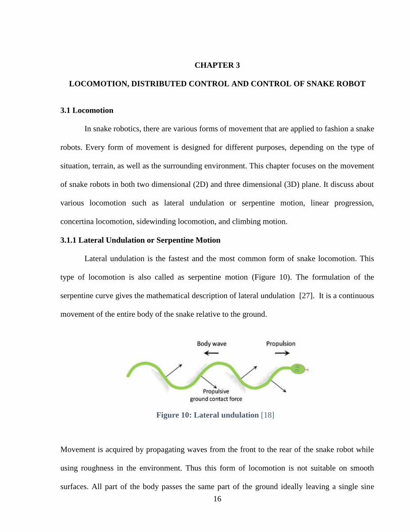
3.1.1 Lateral Undulation or Serpentine Motion
Lateral undulation is the fastest and the most common form of snake locomotion. This
type of locomotion is also called as serpentine motion (Figure 10). The formulation of the
serpentine curve gives the mathematical description of lateral undulation [27]. It is a continuous
movement of the entire body of the snake relative to the ground.
Movement is acquired by propagating waves from the front to the rear of the snake robot while
using roughness in the environment. Thus this form of locomotion is not suitable on smooth
surfaces. All part of the body passes the same part of the ground ideally leaving a single sine
Figure 10: Lateral undulation [18]

17
curved track, while there is never any fixed contact between the ground and any point along the
body [18]. The weight distribution of a snake during this motion is not uniform, but rather
distributed so that the peaks of the body wave curve are slightly lifted from the ground. The
efficiency of lateral undulation is mainly based on two factors: (1) The contour of the ground,
where the more contoured the ground, the more efficient is the locomotion; (2) The ratio between
the length of the snake and its circumference [28].
3.1.2 Linear Progression
In this kind of motion, the snake grapples its body at specific point that appear
continuously move tail wards (Figure 11). Sine waves are directed through the length of the
snake robot, driving it either in forward or in reverse direction. This sine wave is sent through the
vertical modules, which repetitively picks up modules, advances them through the air and places
them slightly forward of their initial position on the ground. The horizontal modules are utilized
only to steer and adjust the robot [20] [27].
3.1.3 Concertina Locomotion
Concertina locomotion are commonly used to navigate through narrow space where the
range of movement is constrained and limited (Figure 12). The term by itself indicates that the
snake stretches and folds its body to move forward. The principle behind concertina locomotion
Figure 11: Linear Progression [27]

18
depends on the difference between the large static friction forces at the anchor points and the low
kinetic friction forces in the part of the body which is extended [18]. By using this principle,
movement is carried out by first pushing the front part of the body forward, while the back part is
curved a few times to give a grapple against the narrow space. Once the head and front part of
the body has crossed the narrow space, the front portion of the body is curved in order to pull the
back part of the body front. This motion is repeated to achieve locomotion [29]. Due to the
stop-and-go movement of the body, momentum is not conserved and, thus, the mode of motion is
not efficient in terms of energy consumption and it is slow. It is seven times less efficient when
compared to other kinds of locomotion in real snakes [20]. However it is often used in order to
traverse tight spaces. But if the path is too narrow when compared to the diameter and the
curving capacity of the snake, then the snake cannot progress by this motion pattern [30].
3.1.4 Sidewinding Locomotion
This type of locomotion is typically utilized on surfaces with low shear, for example,
sand, desert and loose gravel. It is currently one of the fastest ways for these snake robots to
travel through rugged or uneven terrain (Figure 13). Unlike lateral undulation, there is a brief
Figure 12: Concertina locomotion [61]

19
static contact between the body of the snake and the ground. At any given instant, at least two
portions of the snake are in static contact with the ground. The rest of the snake body is lifted and
moved forward. To rotate the robot at the same place the front half of the snake to the right, and
the back half of the snake to the left has the effect of spinning the snake robot in place [31]. In
control point of view one vertical and one horizontal sine wave interact to make the snake robot
move sideways.
3.1.5 Climbing locomotion
There are three kinds of climbing environment - channel climbing, tube climbing and
pole climbing (Figure 14). A variant of linear progression is used to climb each of the above
mentioned environment. First, channel climbing is a variant of linear progression, where the
amplitude and period of the sine wave are adjusted to fit the chosen channel or pipe. Channel
climbing snake robots are often fitted with a protective skin or rubber to provide additional
friction and compliance. No adhesives are used to achieve snake robot channel climbing, only
outward pressure provided by the sine waves. Similar to channel climbing, the snake can also
Figure 13: Sidewinding locomotion [62]

20
climb up the inside of pipes or tubes. A variant of linear progression can be used to climb a pipe
or tube, as in a channel, but since a pipe is cylindrically symmetrical, the snakes can also use a
modified version of corkscrewing to climb a pipe. Pole climbing refers to moving upwards on
cylinders whose perimeter is less than the length of the snake robot. The robot moves upwards
without the aid of any adhesive by spiraling its body around the pole, gripping it, and using the
rolling gait to travel up or down the pole. Snake robots are able to transition directly from
another gait to pole climbing [20].
3.2 Distributed Control and Control of Snake Robots
This section discusses about control of a snake like robot and the way distributed control
is implemented through it. Control of snake robot can be performed using various theories and
methods which have been discussed starting with Central Pattern Generators (CPG), PID
controller and fuzzy logic.
3.2.1 Control of Snake Robots
This section discusses about the different theories and methods of control of snake robot,
starting with Central Pattern Generators (CPG), PID controller and fuzzy logic.
Figure 14: Climbing locomotion [63]
21
3.2.1.1 Central Pattern Generators (CPG)
Central Pattern Generators (CPG) is a new method of control that has been developed
specifically for snake robotics. This method of control is based around trying to solve the
problem of the large amount of computing time that is required to control a system with such a
large amount of DOF [32]. To come up with this solution, the researchers looked at how Nature
solved this problem. They wanted to know how simple creatures like insects could react so
quickly to their environment, when they only have a limited amount of neurons compared to
larger animals such as humans. It was discovered that this is because creatures like these do not
have one control center where they process all of their data, like a human brain. Instead they
have a decentralized collection of neurons that individually process the information, and send
this processed data back to the main processer to be handled. This concept was applied to their
snake robots. By using this technique, they were able to process all of the sensor readings taken
in each of the segments, and then send this processed data up to the head segment (Figure 15).
This technique frees up processing time for the main processer as it does not have to waste time
completing tasks such as waiting for the sensors located in the segments reflected single to be
recorded [33]. As explained in literatures [32] [34], this method allows the individual segments
of the snake robot to control segment orientation, so that better motion of the snake can be
achieved, and each segment can adjust locally for different scenarios, such as applying more
contact force to the ground. By using this method, Wu, et al. [35] are also able to propose a
simplified control method on how to make the snake generate the serpentine type movement by
simply getting a segment to pass its current position to the next segment in line, when it receives
a new position from the control unit [33].

22
Figure 15: CPG Oscillator [34]
3.2.1.2 PID Control
The next method of control that has been investigated is Proportional-Integral-Derivative
(PID) control. PID controllers themselves have been around for a long time implying that there
has been a lot of research conducted into the operation and application of this type of control.
Due to this, Hasanzadeh & Tootoonchi [36] chose to attempt and implement the use of PID
control to a snake robot. To have the capacity to control so many DOF’s, they employed a two
level PID control system. This method works by assigning each segment of the snake an
individual PID controller. This controller is responsible for controlling the torque and the
orientation of the segment that it is assigned to. The next PID controller is called the high level
controller and is responsible for controlling the speed and direction of motion of the snake robot.
The output from this PID controller is fed back into the lower level PID controllers, allowing
them to compensate for the change in direction or speed. So far no evidence of this type of
control method applied to a real robot snake has been found, but simulations show that it has the
ability to react faster than most other methods [33] [36].

23
3.2.1.3 Fuzzy Logic
The last method of control that has been looked at is the application of fuzzy logic in
snake robotics. This form of control has been well researched in many areas of robotics and
control. In this method of control, a lot of data is able to be quickly fused together to enable
quick reactions to obstacles. This would be useful for a robot that operates in 3D, but in the case
of Wu et al. [37], it has been applied to a robot in 2D to test the control theory in a snake
robotics application. The fuzzy logic system works by finding the distance and the angle between
the head of the robot and the target point. From this information, the action that the robot needs
to do to reach the target is determined, for e.g., to go fast if the target is a long way away or slow
if the target is close, and turn [33].
After analyzing the various control method, the CPG method of control is a better option
to be implemented when compared to fuzzy logic and PID control, as it is the best way to solve
problem regarding computation time, which is required by a robot with such a large degree of
freedom. This CPG control is a form of a distributed control system. Therefore, distributed
control was applied in the presented robot. The upcoming section discusses generally about
distributed control system and how it is implemented in snake robot.
3.2.2 Distributed Control
Distributed Control System (DCS) is a specially designed control system used to control
large and complex applications in industrial processes, wherein controllers are distributed
throughout the system. The important characteristic of distributed control system is “centralized
management and decentralized control” [38]. This is in contrast to non-distributed systems,
which uses a single controller at a central location.

24
Figure 16: Functional levels of a typical Distributed Control System [39]
In a DCS, a hierarchy of controllers is connected by communications networks for command and
monitoring. Figure 16 shows the functional levels of a typical DCS [40]. As seen in the block
diagram, the plant consists of elements such as sensors, motors, valve, etc. which are directly
controlled by the microcontrollers, that are in turn controlled by supervisory computers and they
are controlled by coordinating computers. On top of all these computers, the centralized
management lays the computer center which assigns task for all the computers. This is a level 4
DCS which are used in industries to control large, complex and geographically distributed task.
This approach can be implemented in control of snake robots as it has high degree of
freedom. In this thesis work, the proposed snake robot uses the above principal to control the
snake robot. The central pattern generators (CPG) uses this method to control the snake robot
which is discussed in upcoming section. Figure 17 shows the block diagram of distributed
control system of a snake-like robot. It consists of Servo along with position, torque and other

25
sensor in accordance with the design of the robot. These sensors and devices are controlled by
microcontroller, which takes command from the microcomputer located at the head of the snake
robot which is in turn controlled by main computer.
Figure 17: DCS of Snake-like Robot

26
CHAPTER 4
MECHANICAL DESIGN OF MODULAR ROBOT
4.1 Design of Segment Module
Each module of the 3D printed modular robot functioned as single rotational joint with one
Degree of Freedom (DOF). Every module could be rotated 90 degrees with respect to previous
module, as a result enabled the generation of movement utilizing many different methods. Each
module is connected to the previous module in such a way that the axis of rotation is
perpendicular with respect to previous one. The robot was able to generate movement in all three
axis given at least four segments in the chain, since it had two different axis of movement in each
segment pair. In other words, the modules allowed for movement in both vertical and horizontal
axis, hence enabled the robot to move in a 3D plane. The current design consisted of 16 modules
including a head and tail module that can be altered according to the application. This many
modules provided 16 DOF, which can be increased or decreased by simply adding or subtracting
the amount of conjoined modules. Each module was 2.15 inches (5.48 cm) in diameter, and had a
length of 2.95 inches (7.5 cm) in-between the joint axes.
The module comprised of a housing, a Dynamixel servo motor, a Lithium polymer (LiPo)
battery and an internal channel (Figure 18) that allowed the communication and power cables to
be passed down the chain. The housing was constructed via 3D printing using PLA, a commonly
used biodegradable 3D printing material, which contained all of the components within the
module. The torque and velocity required to provide movement to the next module was provided
by the Dynamixel motor. Every module had a single cell (1s) 3.7V LiPo battery inside, which is
connected with two other modules in series that made up to 11.1 volts required to power the
segments. Due to this reason, pairs of three modules should always be used. Then, each

27
segment's power was connected in parallel to the rest of the snake. This allowed for any of the
modules to always have enough current available to them that provided the maximum torque
possible to each of the motors. This allowed all the modules to always have enough current
available to them, in order to provide the maximum torque possible to each of the motors. It also
ensured that each segment of the snake was always powered, whereas the other segments of the
snake were able to operate.
Figure 18: Components of 3D Printed Modular Robot [2]

28
4.2 Housing
The housing consisted of two parts, namely the front housing and the rear housing. The
front housing is the most important part of the module. This comprised space to house both the
battery and the servo motor. As shown in Figure 19, the extra space was provided by B-space
in order to accommodate battery perfectly inside the housing, while the M-space offered the
perfect contact area to hold the servo. Parts of the wall of the module were thinned slightly, so
that the accommodation of the wires providing both
communication and power to the next module was possible. This
was done in a circular pattern around the module, as opposed to
only done in a single place, in order to reduce a weak-spot being
made in the housing wall. The rear housing acted as a cap to
cover the module. Figure 20 depicts the front and rear housing of
the robot.
Figure 19: Front Housing
Cross-sectional View

29
Figure 20: Rear housing
To enable the many different types of movement present when snake robots are considered, a
cylindrical design for the housing was selected. For both rolling and climbing activities, a
cylindrical design was optimal. This housing was designed in such a way that any part of the
robot would not exceed 2.16 inches (5.5cm) in diameter. As the center part of the body is
cylindrical, it could accommodate the structure for the passive wheel adapter, which can be
attached and detached according to the application. This passive wheel adapter provided the
ability for the robot to perform the types of movement that a cylindrical body is not accustomed
to, such as the serpentine type movement.
4.3 Passive Wheel Adaptor
The passive wheel adapter consisted of six passive wheels to be placed 60 degree apart and
attached to the passive wheel support, as shown in Figure 21. The wheels were fastened in
between the wheel holder using paper clip pins. These paper clip pins are cheap and made of

30
steel which act as best axial for the wheels. In between the wheel and the wheel holder, washer
of 1mm thickness was placed in order to reduce friction. Also, in order to slide over each of the
modules, the wheel adapter had a small opening in the support. A screw and bolt was then used
to fasten the passive wheel support together, which enabled the structure to be attached to the
module. Thus, fast serpentine motion was achieved with the help of this device, whilst not
sacrificing the ability for the snake robot to perform the other types of motion when required.
Figure 21: Passive Wheel Adapter [2]
4.4 Actuation
Many different types of Actuation can be used for snake robots such as pneumatic, electric
motor, servos, cable actuation or driven wheels [20] [41]. For this robot, servo motors were
considered. The Dynamixel servo motor was selected due to the presence of on board
microprocessor that provided bus communication, positional feedback, temperature and load
monitoring [42]. In addition, these motors had adjustable torque speed and response control with

31
position, load, voltage, speed, and temperature feedback. This facilitated the formation of a
closed loop control system with relative ease. The servos used TTL or RS-485 serial
communication and allowed for a daisy-chain bus connection at up to 1-3Mbps. The control
algorithm used maintained the shaft positions on the servo, which can be adjusted individually
for each servo that allowed the user to control speed and strength of the motor's response. All of
the sensor management and position control is handled by the servo's built-in microcontroller.
Amongst the Dynamixel servos available, the AX-12A servo was selected for this application
[42]. The most affordable servo with built in microcontroller was this version of the servos. It
operates at 12V 900mA, weighs 55g and provides a stall torque of 15.3 kg.cm. Apart from all of
the features mentioned above, these servos used TTL half-duplex asynchronous serial
communication as well. Therefore due to the above stated advantages and the affordable cost of
the servo, this servo motor was chosen and implemented in current application.
4.5 Three Dimensional (3D) Printing
In order to prototype the casing of the robot, 3D printing was used. 3D printing, otherwise
known as additive manufacturing, is a process of creating three dimensional solid objects from a
digital file [43]. A 3D printed object was created using the additive processes, as opposed to the
subtractive process used by most other techniques, such as by a CNC machine. The process
utilized by this additive manufacturing machine is referred to as the Fused Deposit Modeling
method. In this technique, an object is created by laying down successive layers of material on
top of each other until the whole object is completed. If the horizontal cross section of the final
object was observed, each of these layers could be seen [44]. To 3D print an existing object, the
digital file of the object was made using a 3D scanner. Whereas for the creation of a totally new
object, a Computer Aided Design (CAD) program was used. When the model has been

32
completed, the file was then be saved in a general file type, such as the STL format, which is
processed by software knows as “slicer”. This software converted the model into a series of thin
layers and produced a G-code file containing instructions tailored to a specific type of 3D printer
which enabled the printer to create the model.
3D printing helped in speeding up the prototyping process along with being inexpensive. It
was an immense advantage, because if the same parts were to be manufactured manually it
would take a significantly large amount of time to complete, along with being extremely
expensive due to the labor and machine costs involved. Also, it was easy to find problems in the
design, fix it and then print the design again, when the first module was printed. Due to this, the
accommodation for new communication and power lines was possible.
An open source 3D printer called Lulzbot Taz 4 was used to print each module of the snake
robot, since it supported material such as PLA, ABS, HIPS, Ninja Flex etc. The chosen material
among these materials was PLA (Poly-lactic Acid) because it demonstrated significantly less part
warping, higher maximum printing speeds, lower layer heights, sharper printed corners and
affordable pricing compared to some of the available options. In CAD software, the virtual
design for printing the module was designed, in this case using SolidWorks, and saved in the
STL format. This .stl file was then opened in Cura LulzBot, which acts as the slicer and therefore
converts the model into GCODE as well as allowing the user to control the operation of the 3D
printer.
Unfortunately, there are some disadvantages when using 3D printed parts of this material,
as they are generally neither strong nor durable, in comparison to the parts that might be
constructed using other methods. For this reason, 3D printing is used only for the prototyping
stage of this robot. In case of uses in a potentially hazards environment, such as a collapsed
33
building or a site, where there might potentially be exposure to corrosive environment, the casing
for the modules would require to be produced using either more traditional methods with
stronger metal materials, or be constructed using an industrial grade 3D printer.
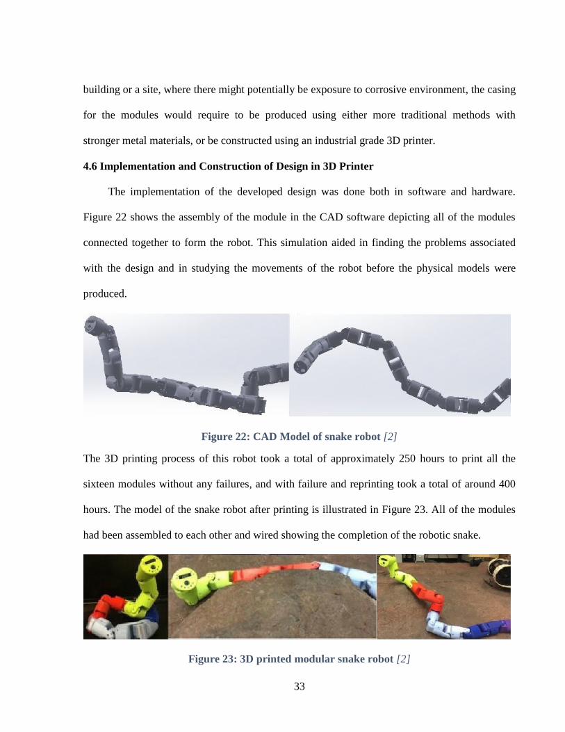
4.6 Implementation and Construction of Design in 3D Printer
The implementation of the developed design was done both in software and hardware.
Figure 22 shows the assembly of the module in the CAD software depicting all of the modules
connected together to form the robot. This simulation aided in finding the problems associated
with the design and in studying the movements of the robot before the physical models were
produced.
Figure 22: CAD Model of snake robot [2]
The 3D printing process of this robot took a total of approximately 250 hours to print all the
sixteen modules without any failures, and with failure and reprinting took a total of around 400
hours. The model of the snake robot after printing is illustrated in Figure 23. All of the modules
had been assembled to each other and wired showing the completion of the robotic snake.
Figure 23: 3D printed modular snake robot [2]

34
The outer face of the 3-D printed materials had relatively low coefficient of friction and fast
wear, especially in rough outdoor environments. In addition, the plastic base cracked easily
under impacts that resulted in pieces of skin falling off the robot. A rubber skin was attached on
the contact surface, as shown in Figure 24, to increase the coefficient of friction. Bicycle tube
was used here, which was cut in small section and slided through each module providing cheap
and efficient solution for increasing the coefficient of friction. Figure 25 shows the ability of
snake robot to attach passive wheel adapter on its body to achieve smooth serpentine motion of
the snake robot, while connecting passive wheel adapter only alternate segments were attached
with passive wheel adapter. Similarly, Figure 26 illustrates that the snake robot had the capacity
to fasten itself to the industrial robot to increase its degree of freedom. When attaching to the
industrial robot, the battery inside each module were removed and external power source was
made available. Depending upon the application, the tail and head of the robot were changed.
Figure 24: Rubber skin attached to the robot
Figure 25: Snake robot with Passive Wheel Adapter

35
4.7 Cost
A breakdown of the components and their cost are provided in Table 4.1. The most
expensive part of the robot was the Dynamixel servos. The features that servos provided were
deemed worthy of the cost. Each servo had an on-board microcontroller that provides bus
communication, motor state feedback such as positional, load, voltage, speed and temperature
feedback [11]. Further relevant features assisted the formation of a closed loop control system
with relative ease as discussed under actuation section.
Figure 26: Snake robot used as End Effector [2]

36
Table 4.1: Cost [2]
S.No Item Quantity Price Each ($) Cost ($)
1 AX-12 Dynamixel Servo Motor 16 $37.5 $600
2 USB2Dynamixel 1 $49.9 $49.9
3 Lipo Battery (3.7V 750mAh) 15 $3.5 $52.5
4 3D printing filament (PLA)
3mm, 1Kg Reel
1 $24.95 $24.95
5 Raspberry Pi Zero 1 $5 $5
6 USB Hub 1 $10.99 $10.99
7 Camera 1 $33.90 $33.90
8 IMU 1 $29.95 $29.95
9 IR Sensor 1 $13.95 $13.95
10 Wifi Module 1 $8.99 $8.99
11 Miscellaneous (Connecting
wires, screws, nuts, etc.)
$65
Total $895.13

37
CHAPTER 5
ELECTRICAL DESIGN OF MODULAR ROBOT
5.1 Control Architecture
In order to control the presented robotic snake, different approaches were considered. The
first approach to be considered was embedding a microcomputer directly into the head unit of the
snake, such as an ODROID, Raspberry Pi or Raspberry Pi zero. This allowed for the local
control of the robot, as Robotic Operating System (ROS) was able to run on-board. The next
feasible approach that had been considered was to utilize a simple micro controller, such as the
Arduino Nano or Arduino Mega 2560, equipped with a Wi-Fi module, so that back and forth
communication from a processing unit, such as a laptop, was possible. This enabled the use of
ROS to control the robot for actuation. This could also allow enabling future applications.
Figure 27: Control Architecture Block Diagram [2]
A description of the proposed setup is depicted in Figure 27. The control unit for the system was
the Raspberry Pi Zero, since it is a very small and inexpensive microcomputer, which was one of

38
the major contributing factor for the choice. It also had the benefit of having a form factor similar
to that of a microcontroller, thus allowing the modular system to stay relatively small.
5.2 Processing Unit
For choosing processing unit, there were many options such as an ODROID, Raspberry
Pi or Raspberry Pi Zero. But in this robot Raspberry Pi zero was used, because of its 1Ghz,
single-core CPU with 512MB RAM that included 40-pin header composite video and reset
headers, and USB On-The-Go ports [45] which allowed additional sensors like USB camera,
IMU sensor, Wi-Fi dongle and usb2dynamixel.
Robot Operating System (ROS) was installed onto a Raspberry Pi Zero which controlled
the angle of all the connected servos, as well as interpreted feedback from the servos such as
position and temperature of each and every servos. ROS is an open source meta-operating
system that offered a message passing interface between processes across a network of installed
nodes [46]. These nodes need not be located on the robot, making it ideal for a mobile robot as
processing can be moved to another unit, assuming it is on the same network. Utilizing a
common messaging systems such as ROS likewise allowed the system to be easily integrated
into a much larger system, which also utilizing this messaging system. This principle was used
and laptop was able to use the ROS environment to access and transmit information to and from
the Raspberry Pi Zero.
5.3 Communication
Communication is an enabling technology in the field of robotics. In this section, we
discuss various communication devices that can be used in this robot for communicating
between the robots and processing unit (i.e. laptop).

39
5.3.1 Bluetooth
Bluetooth is a wireless technology standard for exchanging data over short distances.
They are usually used to connect two or more devices together for the transfer of data by means
of a short-wavelength UHF radio waves in the ISM band from 2.4 to 2.485 GHz. [wiki] [20].
Data rate provided by Bluetooth varies by the Bluetooth communication protocol used by the
device with 1 Mbps for the low-energy protocol, 1 Mbps for Version 1.2, up to 3 Mbps for
Version 2.0 EDR and up to 24 Mbps for Version 3.0 HS [47] [48] The range of the Bluetooth
devices is 10 meter figure for class 2 radio devices and they are limited to many real world factor
such as wall or any barrier decreases the range of the device. The 2.4 GHz radio frequency used
by Bluetooth is strongly absorbed by water. Application of Bluetooth is prominent in robotics as
most mobile phones support Bluetooth protocols and the user to design an application for
controlling robots via the phone. A good example of a robot with Bluetooth is the LEGO
Mindstorms Robot, which is mainly used for educational use [49]; implementation of various
programmable activities of the robot can be started though software installed on compatible cell
phones.
5.3.2 ZigBee Pro
ZigBee Pro is a wireless technology developed for low power, low data rate, wireless
communication applications. The ZigBee standard operates on the IEEE 802.15.4 physical radio
specification and operates in unlicensed bands including 2.4 GHz, 900 MHz and 868 MHz [50].
Its low power consumption limits transmission distances to 10–100 meters line-of-sight,
depending on power output and environmental characteristics. ZigBee devices can transmit data
over long distances by passing data through a mesh network of intermediate devices to reach
more distant ones [51]. Applications using ZigBee are typically those of control and remote

40
sensing operations, such as industrial automation, home automation, smart energy metering and
grid monitoring [52], which benefit from the low power consumption of the radio modems.
ZigBee radio modems are also used in robotics as they are simple to integrate into designs of
robots through a serial or USB connection. ZigBee devices support various network topologies
including mesh networks which allow for capabilities for a robot system to operating over large
areas [48].
5.3.3 Wi-Fi
Wi-Fi is a technology that allows electronic devices to connect to a wireless LAN
(WLAN) network, mainly using the 2.4 gigahertz (12 cm) UHF and 5 gigahertz (6 cm) SHF ISM
radio band [53]. The IEEE 802.11 standard is used in these Wi-Fi. It is a set of media access
control (MAC) and physical layer (PHY) specifications for implementing wireless local area
network (WLAN) computer communication in the 2.4, 3.6, 5, and 60 GHz frequency bands [53].
Wi-Fi IEEE 802.11 is an attractive option for wireless communication for robotics because of its
already common use and compatibility with internet communication protocols [48]. Wi-Fi is
used in many devices including laptops, smaller internet notebooks (netbooks), video game
consoles, digital cameras and smartphones for the purpose of connecting to a wireless network
that provides access to the Internet. Use of Wi-Fi for robotics is limited to the range and power
consumption of Wi-Fi hardware. Range of Wi-Fi is dependent upon many factors including the
Wi-Fi protocol and the use of single or multiple antenna in the radio device; a typical range is
provided as being between 50 meters to 150 meters, assuming there is no interferences to the
signal such as walls, buildings and electronic interferences in the 2.4 GHz range [53]. In this
robot Edimax, Wi-Fi dongle is used. It supports 150Mbps 802.11n, Wi-Fi USB adapter, Nano
size which is ideal for Raspberry Pi.

41
5.4 Head
The head was equipped with a camera, an IR sensor, an IMU and the Raspberry Pi zero. In
addition, an LED was installed for illumination during pipeline inspection during night and in a
dark environment. In order to find the distance of an obstacle or an object in front the robot, the
IR sensor was used. This is useful because it allowed the robot to pick an object, when an end
effector was attached to the head of the snake. An Internal Measurement Unit (IMU) with
10DOF was used, which gives 11 axes of data: 3 axes of accelerometer data, 3 axes gyroscopic,
3 axes magnetic (compass) and temperature, which made it possible for many different
applications [54]. Raspberry Pi Zero, the microcomputer used here, acts as a data exchange hub.
All of the different sensors, as well as the servo motors, were attached to the Raspberry Pi Zero
via a USB hub. Using a standard connection such as a USB, also enabled the rapid expandability
of the system because, many different sensors have this interface available. The Raspberry Pi
Zero collected all of the available data from the robot such as the camera, IR, IMU, position,
load, voltage, speed and temperature data, and sent it to the processing unit via a Wi-Fi
connection. The processing unit calculated the required positions that the servo needs to be in.
This information was then transmitted to the microcomputer, which was able to move the
attached servos to the desired positions.
5.5 Body
The body consisted of a chain of modules connected together in series. The servos inside
the module used TTL serial communication to receive commands and send back sensor data to
the microcontroller. A daisy-chain wiring scheme was applied to this system, in which multiple
servo were connected together in a series sequence, thus reducing the number of wires required

42
in the robot. This daisy-chain approach moreover allowed for the system to be quickly scaled up
or down as needed.
5.6 Tail
The tail of the robot was a specialized module. It constituted of a switch to turn off and on
and to charge the robot. It also consisted of an opening for connection to the tether and a socket
for charging the robot. This tail could be modified depending upon the application, for instance,
it can be modified to carry a small camera to allow the user to lift up the tail and see the front
portion of the robot.
5.7 Power Source and Distribution
The robot could be powered either through battery fitted inside the robot or using tether
carrying power and communication. This robot was opted with both the options, so that it could
be used depending on the application. If the robot is used for search and rescue, or pipeline
inspection, or any other application, which requires the robots to navigate and move, then battery
source option can be used rather than tether; since tether makes it unable to navigate too far away
from a base station and tether could also potentially become entangled on various objects in the
environment. In the case in which this robot is used as end effector, then the tether option can be
used and the battery can be removed, as the battery reduces the overall weight and thus, allowing
robot to increase its payload capacity, as the payload capacity depends on the length and weight
of the link. The subsection of this topic discuss tether and various battery option.
5.7.1 Tether
Tethering is the practice of using a mobile device such as a robot to connect another device,
such as a laptop or any computing device. In this robot, the tether carried both power and
communication cable. Figure 28 shows the connection diagram [55]. At one end, it was
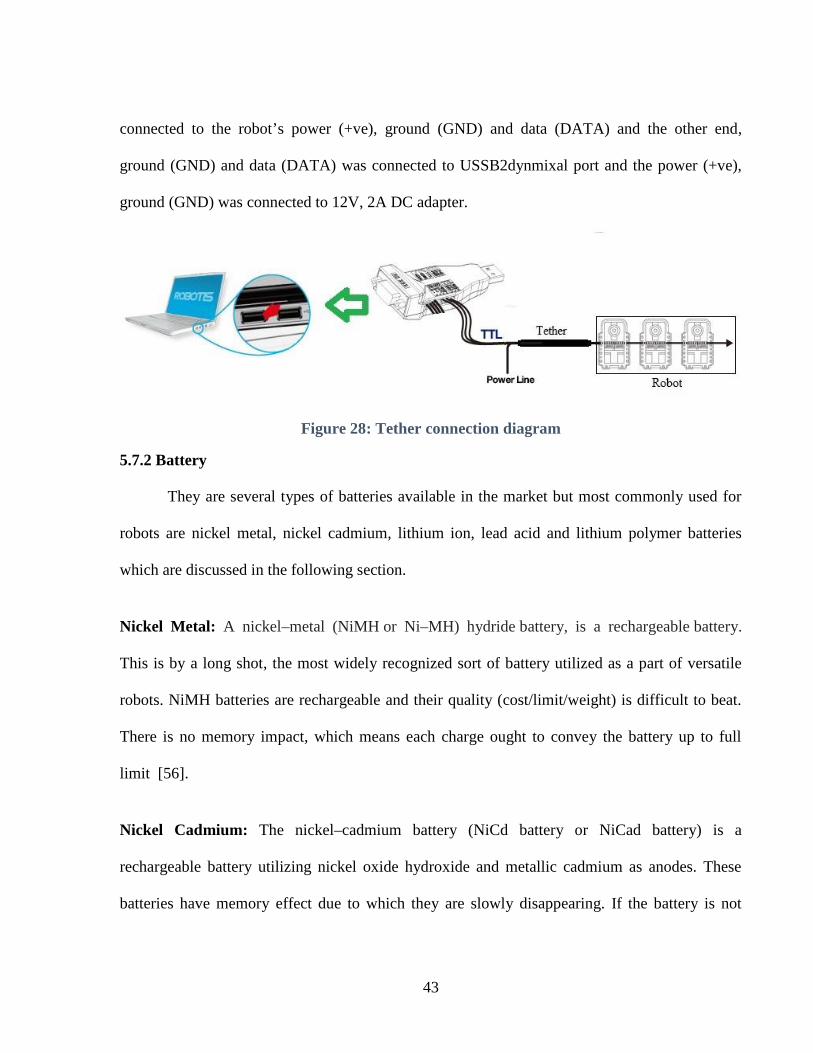
43
connected to the robot’s power (+ve), ground (GND) and data (DATA) and the other end,
ground (GND) and data (DATA) was connected to USSB2dynmixal port and the power (+ve),
ground (GND) was connected to 12V, 2A DC adapter.
Figure 28: Tether connection diagram
5.7.2 Battery
They are several types of batteries available in the market but most commonly used for
robots are nickel metal, nickel cadmium, lithium ion, lead acid and lithium polymer batteries
which are discussed in the following section.
Nickel Metal: A nickel–metal (NiMH or Ni–MH) hydride battery, is a rechargeable battery.
This is by a long shot, the most widely recognized sort of battery utilized as a part of versatile
robots. NiMH batteries are rechargeable and their quality (cost/limit/weight) is difficult to beat.
There is no memory impact, which means each charge ought to convey the battery up to full
limit [56].
Nickel Cadmium: The nickel–cadmium battery (NiCd battery or NiCad battery) is a
rechargeable battery utilizing nickel oxide hydroxide and metallic cadmium as anodes. These
batteries have memory effect due to which they are slowly disappearing. If the battery is not
44
discharged properly but still recharged it to full capacity, then a part of the capacity is lost each
time [57].
Alkaline Battery: Alkaline batteries are a type of primary battery dependent upon the reaction
between zinc and manganese oxide. They are not rechargeable battery but a rechargeable
alkaline battery allows reuse of specially designed cells. These are the least expensive batteries
in the short term, and provide a higher voltage than NiMh, but are not great for the environment,
and requires replacements often [58].
Lithium Ion: A lithium-ion battery (Li-ion) is a rechargeable battery in which lithium ions move
from negative electrode to positive electrode during discharge, and back when charging. They
are one of the most popular types of rechargeable batteries for portable electronics, with a high
energy density, small memory effect, and only a slow loss of charge when not in use. Since
lithium-ion chemistry does not have a "memory", partial discharge does not harm the battery
pack. But, if the voltage of a lithium-ion cell drops below a certain level, it is ruined. Lithium-ion
batteries age and they only last two to three years, even if they are sitting on a shelf unused [59].
Lithium Polymer: Lithium ion polymer also known as 'lipo' or 'lipoly' batteries. They are
rechargeable battery in which lithium ions move from negative electrode to positive electrode
during discharge and vice-versa when charging. Li-ion batteries uses an intercalated lithium
compound as one electrode material, compared to the metallic lithium used in a non-rechargeable
lithium battery. The electrolyte, which allows for ionic movement, and the two electrodes are the
constituent components of a lithium-ion battery cell [60]. They are fast becoming the most
popular type of battery because of their light weight, high discharge rates, energy density, and
small memory effect, low self-discharge and relatively good capacity, except the voltages

45
increase in increments of 3.7V. Lithium-ion batteries can be dangerous under some conditions
and can pose a safety hazard since they contain, unlike other rechargeable batteries, a flammable
electrolyte and are also kept pressurized. So for safety it should never be charged or used when
unattended [61].
5.7.3 Battery selection and Schematic diagram
Among the various battery types discussed above, Lipo battery was used due to the
advantages discussed above; in which the main feature that attracted and made more suitable for
this robot is its light weight and high discharge rate. The lipo battery with rating 3.7V, 720mAh,
20C lipo battery was used whose dimension were 1.68 x 0.96 x 0.32 inch, which perfectly fit
inside each module of the robot. Figure 29 shows the schematic diagram of the connection.
Figure 29: Schematic diagram of battery connection
Each module had a single cell (1s) 3.7V LiPo battery inside, which was connected with two other
modules in series to make up the 11.1 volts required to power the segments. Therefore, pairs of
three modules should always be used. Each segment’s power was then connected in parallel to

46
the rest of the snake. This would allow for any of the modules to always have enough current
available to them to provide the maximum torque possible to each of the motors. It also ensured
that each segment of the snake would always be powered while the other segments of the snake
were able to operate.

47
CHAPTER 6
CONTROL ALGORITHM
As described in Chapter 3, the finest way to implement the control of snake robot is
through Central Pattern Generator, which is a form of distributed control system. In this chapter,
a control algorithm is written to get locomotion based on square wave type motion, climbing
algorithm to climb a pole and a standing cobra position for surveillance. The control of
serpentine motion is also presented.
6.1 Square Wave Motion Algorithm
The basic idea for this movement was inspired by sidewinding locomotion. In this
motion, there was always contact between the body of the robot and the surface of ground unlike
serpentine motion. At any given instant, at least two contact points of the snake were in contact
with the ground. The movement was generated due to difference in the friction, which was
created by adjusting the contact surface between body of snake robot and the ground (Figure 30).
If the back portion of the robot had more contact with ground when compared to the front
portion, then the friction in the back was more than front. Then, when square wave propulsion
was applied the robot, it moved forward due to difference in the friction. The algorithm for this
kind of motion is shown in Figure 32 and is discussed below.
Step 1: First, curve fitting procedure is implemented to optimize the entire robot which make the
shape of the robot in the form of square wave
Step 2: Once the curve fitting procedure is executed, then the robot configure itself to create four
contact point A, B, C and D. These contact points are then formed by using both even and odd
joints. Even joints in the module are those which bends in the vertical plane, whereas odd joints
in the module bends in horizontal plane.

48
Figure 30: CAD Model of Square Wave
Step 3: After the initial configuration are obtained, the contact points A and B have low friction
as compared to points C and D. This is achieved by lifting the even modules on the vertical plane
to a degree of β such that there is less contact surface area on the ground. The joints connecting
the contact points (A, B), (B, C), (C, D) have no contact surface area with the ground which is
attained by lifting the even module in the vertical plane to a degree of α as shown in Figure 30.
Figure 31: Friction distribution of Square Wave Motion

49
Figure 32: Control Algorithm for Square Wave

50
Now the positive cycle propulsion was applied, the snake robot took the shape of square wave
starting from positive cycle of the square wave. The positive cycle propulsion was applied until it
reached the desired angles. If the desire angles were reached, then the algorithm moved to next
step or it checked the load feedback value to verify whether the servo was moving or not. Once
the positive cycle propulsion was completed, then the negative cycle propulsion was applied
which generated resultant force due to difference in the friction, thus, pushing the robot forward.
6.2 Pole Climbing Algorithm
The control algorithm used for climbing is given in Figure 34. The closed-loop control of
the mechanism’s locomotion had been possible with the positon and torque sensors located
inside the servo of each module. The steps involved are explained as follows.
Step 1: The pole fitting procedure is used to optimize the entire robot with respect to the pole,
i.e. the robot is adjusted according to the diameter of the pole. With the proposed control
algorithm for climbing, the robot can climb a pole of diameter ranging from 30mm to 80mm. In
this method, two contact points upper contact point (A) and lower contact point (B) are used to
grab and climb the pole. To grab the pole, four modules are used to create a single contact point.
For instance, module no. 2 to module no. 5 are used to create a single contact point as module
no. 1 being the head, module no. 2 and module no. 5 grips the pole and module nos. 3 and 4 are
to adjust the contact point with respect to the diameter of the pole. Module nos. 3 and 4 close to
hold the pole and they open to release the pole. Module nos. 6, 7 and 8 are used to lift and pull
(propulsion point) the contact point, where module nos. 6 and 8 provide the propulsion and
module no. 7 is in the perpendicular plane to the pole, so it adjusts itself with the pole and the
modules from 9 to 12 in order to create lower contact point in a similar way.

51
Step 2: Once the pole fitting procedure is done, then the next step is to go to the initial
configuration with two contact points A (upper contact point) and B (lower contact point) firmly
grabbing the pole (Figure 33(a)).
Step 3: After the initial configuration is obtained, only the upper contact point (A) is released
and propulsion is provided to lift the point A. The propulsion is provided until it reaches the
desired angles (Figure 33(b)). If the desired angles are reached, then the algorithm move to Step
4 or it checks the load feedback value to verify whether the servo is moving or not.
Step 4: As soon as the propulsion is provided and required angle is reached, then the contact
point (A) grabs the pole and again, the angle and load feedback are checked to confirm whether
the upper contact point has held the pole (Figure 33(c)). Once the contact point (A) holds the
pole firmly, then contact point B is released and propulsion is provided to pull upwards and then,
the contact point (B) holds the pole (Figure 33(d)).
Figure 33: CAD Model of Robot Climbing

52
Figure 34: Control Algorithm for Climbing

53
The procedure was repeated from Step 3 to climb the pole. The robot climbed 100mm for
every propulsion. To lift the contact point A from its initial positon, the servo was moved 50°
from angle 90° to 40°, and to pull the contact point B, the servo was moved 50° from angle 40°
to 90°. In every step, the angle and load feedback were checked to confirm whether the task was
completed.
6.3 Standing Cobra Position for Surveillance
The snake robot in standing cobra position is the best position for surveillance from ground
while on the mission. Figure 35 shows the snake robot in cobra position. At this position, the
head was in the air with 5 DOF to move around and got wide range of view through camera.
Figure 35: CAD model of Standing Cobra Position

54
The height of the head could be varied by adjusting the module position. All the even modules
angles A, C and E were increased or decreased to vary the height of the robot’s head from the
ground and the odd modules B and D were changed to vary the view in horizontal plane. Thus by
performing this, a complete 360° view was achieved at various heights. This positon was
controlled manually by the user at the remote place to move the head by sending direct angles to
the servo.
7.4 Sine Wave Motion with Passive Wheel
This type of motion was produced by a sinusoidal wave being formed with the individual
module of the snake robot. As the wave moved through the time domain, the snake robot should
be able to generate forward motion. This forward motion was generated by the fact that passive
wheels were used on the base of the snake robot.
The passive wheels was used to generate different coefficients of friction in different
planes. This was achieved by the wheels ability to only roll in one direction. Because of this, a
low coefficient of friction was generated in the direction of wheel spin, where a high coefficient
of friction was generated in the opposing direction. This motion was governed by the equation
given below. From this equation, it is evident that if the coefficient of friction of y axis is greater
in than x axis, then the force along the y axis will be greater than force aplied in x axis [34].

55
Figure 36 shows how the forward motion is generated. If the force on the left side and on the
right side are same, then the resultant force would be in forward direction. This is because, a
resulting force in the direction of wheel spin is to be significantly greater than the force that was
obtained in the alternate direction. To turn left, the force on the left side is greater than that of
right side causing the robot to move in left direction as shown in Figure 37. Similarly to turn
right, the force at on the right side is greater than left side causing the robot to move in right
direction. Figure 38 shows how the robot is maneuvered in a smooth surface.
Figure 36: Forward Motion generated by Passive Wheel
Figure 37: Left and Right turning using Sine Wave
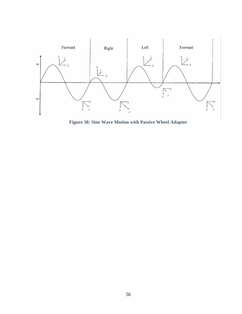
56
Figure 38: Sine Wave Motion with Passive Wheel Adapter

57
CHAPTER 7
EXPERIMENTAL RESULT
7.1 Testing Microcomputer and Communication
The microcomputer used in this robot was Raspberry Pi Zero. As discussed in Chapter 5,
Robotic Operating System (ROS) was used as platform to control the robot. The Raspberry Pi
Zero uses Raspbian Linux operating system (OS). In this OS, the Raspbian Jessie was installed.
To install the ROS in this operating system, there was a different version of ROS which is
ROSberryPi.
Once the ROS was installed the microcomputer, the next step was to install
Dynamixel_controllers package. This package contained a configurable node, services and a
spawner script to start, stop and restart the controller plugins. Reusable controller types were
characterized for common Dynamixel motor joints. Speed, position and torque could be set for
individual servo [62]. After the package had been installed, a launch file was written which
would set all necessary parameters to start up the controller manager that will connect to the
motors and publish raw feedback data (e.g. current position, goal position, error, etc.) at a
specified rate. When the controller manager was created and launch file was run, the controller
manager was publishing feedback on /motor_states/pan_tilt_port topic. The rostopic echo was
used to display the feedback of the servo. Each servo were identified by their ID number. In this
case, the ID were assigned from 11 to 26 as there were sixteen servo connected. Figure 39 shows
the confirmation of communication working as all the raw feedback data from sensor are
received data.

58
Figure 39: Data Feedback Communication
7.2 Testing Servo and Controlling its Position
In this section, the testing of servo and controlling its position were done by creating a joint
controller with motors. First, a configuration file was created which contained all parameters like
motor id, initial position, minimum and maximum position, joint speed etc. which were
necessary for the controller. This configuration file was saved as tilt.yaml file. Subsequently, a
launch file was created, which loaded controller parameters to the parameter server and started
up the controller (start_tilt_controller.launch). Then, once the communication bus was
established by running the control manger then this configuration file was launched. Then, to run
the servo rostopic pub -1 /tilt_controller/command std_msgs/Float64 was used [63]. Figure 40
shows the servo moving from 90° to 0° and the load of the each servo.

59
Figure 40: Position and Load Feedback
7.3 Snake Robot in Standing Cobra Position
The snake robot in cobra posture is the ideal position for surveillance from ground while
performing a task. Figure 41 shows the snake robot executing the standing cobra position. At this
point, the head was in the midair with 5 DOF to move around and was able to acquire a complete
360° view through camera. The height of the head could be increased or decreased by adjusting
the module position.

60
Figure 41: Cobra Position for surveillance
7.4 Square Wave Motion of Snake Robot
The square wave motion of snake robot was executed based on the control algorithm
explained in Chapter 6. Figure 42 shows the implementation of square wave motion where two
complete cycle of square wave was executed, i.e. two positive cycle propulsion and two negative
cycle propulsion. The snake robot travelled 200mm per one complete cycle.
Figure 42: Square Wave Locomotion [2]
7.5 Climbing of Snake Robot
The climbing of snake robot was achieved based on the climbing algorithm described in
Chapter 6. Figure 43 shows the execution of climbing algorithm where five complete cycle of the
algorithm was executed, climbing a distance of 500mm as the robot climbs 100mm for every
propulsion.

61
Figure 43: Pole Climbing

62
CHAPTER 8
CONCLUSION AND FUTURE WORKS
In this research work, the design, control and implementation of a 3D printed snake robot
has been presented. From literature, the current state of snake robotics, focusing on the design of
different types of snake robots that have been constructed over the decades were reviewed along
with currently implemented snake robots. In Chapter 3, the control of the snake robot was
focused, where it was decided that Central Pattern Generators (CPG) is the best control method
to use for this type of robot. In Chapter 4, the mechanical design of the robot is shown. In
addition, the design process and construction of both the modules for the snake were discussed,
as well as, the construction of different add-ons required to generate different forms of
movement, such as the serpentine motion. 3D printing as a fast manufacturing process was also
presented and shown how this method of construction is ideal for prototyping this type of robot;
as the relatively complicated segments can be produced much faster than the traditional methods
of construction. In Chapter 5, the electrical design of the robot was concentrated on, where the
many subsystems of the robot were presented such as the power distribution system used, as well
as the various sensors and the microcomputer that enabled both local control and sensor
processing, this being Raspberry Pi Zero. In Chapter 6, the control of the robot was delved into
focusing on the three types of movement that has been achieved with the constructed robot; these
being serpentine motion, square wave motion and the ability for the robot to climb up a
cylindrical poll. Finally in Chapter 7, the experimental results of the robot was shown where all
stages of the design were explained. Testing the various components of the robot such as the
microcomputer, all the way through to the implementation of the robot itself, during the different
movement patterns that were explained in Chapter 6 was discussed. From this, one can see that

63
the design, construction and control of a high degree of freedom system, this being a snake robot,
has been successfully accomplished.
Even though the basic functionality of this type of robot has been presented in this
research, the future work with this system could be taken down many different avenues. The
design of the segments could be optimized, with other factors being considered into the design to
be taken into account, such as material selection to enable more grip to be considered. A study
into how a real snake is able to achieve the same motions without the use of passive wheels
should also be undertaken, such as by determining whether the direction, size and placement of
their scales is a significant factor. Waterproofing of the snake robot could be considered as
having a robot of this type to be able to enter the water could have many applications, such as
during reconnaissance and the ability to traverse pipes with liquid inside them. More movements
of a snake robot, and how the current movements employed to this robot behave in different
environments as well as different algorithms that could be used to control the robot should be
looked into. For example, as the snake robot should be able to be inserted into a pipe, which
method would work best to traverse the pipe and can the current robot achieve these movements?
Lastly, the automation of this type of robot should be thoroughly explored. In literature, a lot of
work has been completed into the creation and movements employed by these systems, but little
work has been conducted into the autonomous deploying of these units, with many robots being
tele-operated. Many challenges will have to be overcome, such as the ability for the robot to
accurately localize and path plan using its non-uniform movement structure. Other algorithms
that are becoming popular with other types of robots should be tested, such as SLAM, which will
become significantly more difficult as these systems do not have a fixed point to use as a

64
reference point for the entire robot as well the robot have to move much more to achieve a
smaller displacement.

65
REFERENCES
[1] G. Bekey, R. Ambrose and V. Kumar, Robotics: State of the Art and Future Challenges,Singapore: ProQuest ebrary, 2008.
[2] I. H. Mohammed, B. Champion, N. Gallardo, P. Benavidez and M. Jamshidi, "Design andControl Architecture of a 3D Printed Modular Snake Robot," World Automation Congress(WAC), IEEE, 2016.
[3] C. Wright and e. al., "Design of a modular snake robot," in IEEE/RSJ InternationalConference on Intelligent Robots and Systems, 2007.
[4] A. Johnson and e. al., "A novel architecture for modular snake robots," tech. rep. RoboticsInstitute, pp. 1-8, 2011.
[5] "Snakebot," Wikipedia, [Online]. Available: https://en.wikipedia.org/wiki/Snakebot.[Accessed 16 January 2016].
[6] G. S. Chirikjian and J. W. Burdick, "The kinematics of hyper-redundant robot locomotion,"EEE transactions on robotics and automation, vol. 11, no. 6, pp. 781-793, 1995.
[7] S. Hirose and M. Makoto, "Biologically inspired snake-like robots," in Robotics andBiomimetics: IEEE International Conference on .IEEE, 2004.
[8] S. Hirose and H. Yamada, "Snake-like robots [tutorial]," IEEE Robotics & AutomationMagazine, pp. 88-98, 2009.
[9] H. Yamada and e. al., "Development of amphibious snake-like robot ACM-R5," in Proc.ISR2005, 2005.
[10] T. Takayama and S. Hirose, "Amphibious 3D active cord mechanism "HELIX" with helicalswimming motion," in Intelligent Robots and Systems, 2002. IEEE/RSJ InternationalConference on. Vol. 1. IEEE, 2002.
[11] S. Yu and e. al., "An amphibious snake-like robot: Design and motion experiments onground and in water," in Information and Automation, 2009. ICIA'09. InternationalConference on. IEEE, 2009.
[12] S. Chigisaki and e. al., "Design and control of amphibious Snake-like Robot ACM-R5," inNippon Kikai Gakkai Robotikusu, Mekatoronikusu Koenkai Koen Ronbunshu (CD-ROM),2005.
[13] H. Ohno and S. Hirose, "Design of slim slime robot and its gait of locomotion," inIntelligent Robots and Systems: Proceedings of IEEE/RSJ International Conference on. Vol.2. IEEE, 2001.
[14] H. Yamada and S. Hirose, "Development of practical 3-dimensional active cord mechanismACM-R4," Journal of Robotics and Mechatronics, vol. 18, no. 3, p. 305, 2006.
[15] H. Kimura and S. Hirose, "Development of Genbu: Active wheel passive joint articulatedmobile robot," in Intelligent Robots and Systems, 2002. IEEE/RSJ International Conferenceon. Vol. 1. IEEE, 2002.
[16] S. Hirose, "Snake, walking and group robots for super mechano-system," in Systems, Man,and Cybernetics, 1999. IEEE SMC'99 Conference Proceedings. 1999 IEEE InternationalConference on. Vol. 3. IEEE, 1999.
[17] J. K. Hopkins, B. W. Spranklin and S. K. Gupta, "A survey of snake-inspired robot

66
designs," Bioinspiration & biomimetics, vol. 4, no. 2, 2009.[18] P. Liljebäck and e. al., Snake robots: modelling, mechatronics, and control, London:
Springer-Verlag, 2012.
[19] C. Wright and e. al., "Design and architecture of the unified modular snake robot," inRobotics and Automation (ICRA), 2012 IEEE International Conference on. IEEE, 2012.
[20] "Snake-arm Robots," OcRobotics, [Online]. Available:http://www.ocrobotics.com/technology-/snakearm-robots/. [Accessed 15 July 2016].
[21] "Snake-arm Robots," OcRobotics, [Online]. Available:http://www.ocrobotics.com/technology-/snakearm-robots/. [Accessed 15 July 2016].
[22] C. Wright, A. Buchan, B. Brown, J. Geist, M. Schwerin, D. Rollinson, M. Tesch and H.Choset, "Design and architecture of the unified modular snake robot," in Robotics andAutomation (ICRA), 2012 IEEE International Conference on. IEEE, 2012.
[23] S. Yu, S. Ma, B. Li and Y. Wang, "An amphibious snake-like robot: Design and motionexperiments on ground and in water," in Information and Automation, 2009. ICIA’09.International Conference on. IEEE, 2009.
[24] A. Crespi and A. J. Ijspeert, "Amphibot ii: An amphibious snake robot that crawls andswims using a central pattern generator," in Proceedings of the 9th international conferenceon climbing and walking robots (CLAWAR 2006), no. BIOROB-CONF-2006-001, 2006.
[25] T. Aoki, H. Ohno and S. Hirose, "Design of slim slime robot ii (ssr-ii) with bridle bellows,"in Intelligent Robots and Systems, 2002. IEEE/RSJ International Conference on, vol. 1.IEEE, 2002.
[26] "Modular snake robots:gaits," Biorobotics Laboratory: Carnegie Melon University, 2008.[Online]. Available: http://biorobotics.ri.cmu.edu/projects/modsnake/newwebsite/gaits/.[Accessed 15 July 2016].
[27] M. Tesch and e. al, "Parameterized and scripted gaits for modular snake robots," AdvancedRobotics, vol. 23, no. 9, pp. 1131-1158, 2009.
[28] A. A. Transeth, Modelling and control of snake robots, Norwegian University of Scienceand Technology, 2008.
[29] A. Akbarzadeh and e. al., "Generating snake robot concertina locomotion using a newdynamic curve," International Journal of Modeling and Optimization, vol. 1, no. 2, p. 134,2011.
[30] M. Walton, B. C. Jayne and A. F. Bennett, "The energetic cost of limbless locomotion,"Science, vol. 249, no. 4968 , pp. 524-527, 1990.
[31] S. M. Secor, B. C. Jayne and A. F. Bennett, "Locomotor performance and energetic cost ofsidewinding by the snake Crotalus cerastes," Journal of experimental biology, vol. 163, no.1, pp. 1-14, 1992.
[32] T. Sato, T. Kano and A. Ishiguro, "A snake-like robot driven by a decentralized control thatenables both phasic and tonic control," in 2011 IEEE/RSJ International Conference onIntelligent Robots and Systems. IEEE, 2011.
[33] B. Champion, Investigation of snake robotics and a construction of this type of Robot,Australia: Deakin University Australia Academic, 2013.
[34] X. Wu and S. Ma, "Autonomous collision-free behavior of a snake-like robot," in Robotics

67
and Biomimetics (ROBIO), 2010 IEEE International Conference on. IEEE, 2010.[35] X. Wu and S. Ma, "CPG-controlled asymmetric locomotion of a snake-like robot for
obstacle avoidance," in Robotics and Biomimetics (ROBIO), 2009 IEEE InternationalConference on. IEEE, 2009.
[36] S. Hasanzadeh and A. A. Tootoonchi, "Obstacle avoidance of snake robot moving with anovel gait using two-level PID controller," in 2008 IEEE Conference on Robotics,Automation and Mechatronics. IEEE, 2008.
[37] Q. Wu and e. al., "Obstacle avoidance research of snake-like robot based on multi-sensorinformation fusion," in Robotics and Biomimetics (ROBIO), 2012 IEEE InternationalConference on. IEEE, 2012.
[38] W. Yi and e. al., "A distributed control system for the different types of air compressors," inControl Conference (CCC), 2012 31st Chinese. IEEE, 2012.
[39] "Distributed control system," Wikipedia, [Online]. Available:https://en.wikipedia.org/wiki/Distributed_control_system. [Accessed 15 July 2016].
[40] "Distributed control systems," Wikipedia, 3 July 2016. [Online]. Available:https://en.wikipedia.org/wiki/Distributed_control_system. [Accessed 15 July 2016].
[41] K. J. Dowling, Limbless locomotion: learning to crawl with a snake robot, NASA, 1996.
[42] "Dynamixel-ax-12a-servo," Generation Robots, [Online]. Available:http://www.generationrobots.com/media/Dynamixel-AX-12-usermanual.lpdf . [Accessed 20May 2016].
[43] "3D Printing," Wikipedia, [Online]. Available: https://en.wikipedia.org/wiki/3D_printing.[Accessed 15 July 2016].
[44] "What is 3D printing?," 3DPrinting.com, [Online]. Available: http://3dprinting.com/what-is-3d-printing/. [Accessed 15 July 2016].
[45] "Raspberry Pi Zero," Raspberry Pi Foundation, [Online]. Available:https://www.raspberrypi.org/products/pi-zero/. [Accessed 15 July 2016].
[46] "Robotics Operating System," Wikipedia, [Online]. Available:https://en.wikipedia.org/wiki/Robot Operating System . [Accessed 15 July 2016].
[47] "Bluetooth Technology Basics," Bluetooth SIG Inc., 2016. [Online]. Available:https://www.bluetooth.com/what-is-bluetooth-technology/bluetooth-technology-basics.[Accessed 15 July 2016].
[48] P. J. Benavidez, Design of a swarm of autonomous ground vehicles for use in remotesensing applications, San Antonio: University of Texas at San Antonio. Department ofElectrical and Computer Engineering, 2010.
[49] "Build a robot," Lego® Mindstorms® EV3, [Online]. Available: http://www.lego.com/en-us/mindstorms/build-a-robot. [Accessed 15 July 2016].
[50] "ZigBee Wireless Standard," Digi International Inc., [Online]. Available:http://www.digi.com/resources/standards-and-technologies/rfmodems/zigbee-wireless-standard. [Accessed 15 July 2016].
[51] "ZigBee," Wikipedia, [Online]. Available: https://en.wikipedia.org/wiki/ZigBee. [Accessed15 July 2016].
[52] "Certified Projects Overview," ZigBee Alliance, [Online]. Available:

68
http://www.zigbee.org/Products/CertifiedProducts/CertifiedProductsOverview.aspx.[Accessed 20 May 2016].
[53] "Wi-Fi," Wikipedia, [Online]. Available: https://en.wikipedia.org/wiki/Wi-Fi. [Accessed 15July 2016].
[54] "Adafruit 10-DOF IMU Breakout - L3GD20H + LSM303 + BMP180," Adafruit, [Online].Available: https://www.adafruit.com/product/1604. [Accessed 15 July 2016].
[55] "USB2Dynamixel," Robotica Educativa and Personal, [Online]. Available: http://www.ro-botica.com/Producto/USB2Dynamixel/. [Accessed 15 July 2016].
[56] "Nickel," Wikipedia, [Online]. Available: https://en.wikipedia.org/wiki/Nickel. [Accessed15 July 2016].
[57] "Nickel Cadmium Battery," Wikipedia, [Online]. Available:https://en.wikipedia.org/wiki/Nickel%E2%80%93cadmium_battery. [Accessed 15 July2016].
[58] "Alkaline Battery," Wikipedia, [Online]. Available:https://en.wikipedia.org/wiki/Alkaline_battery.
[59] "Lithium Ion Battery," Wikipedia, [Online]. Available:https://en.wikipedia.org/wiki/Lithium-ion_battery. [Accessed 15 July 2016].
[60] "Lithium Polymer Battery," Wikipedia, [Online]. Available:https://en.wikipedia.org/wiki/Lithium_polymer_battery.
[61] C. Benson, "Basics: How to I choose battery?," RobotShop Inc., 15 January 2013. [Online].Available: http://www.robotshop.com/blog/en/how-do-i-choose-a-battery-8-3585.[Accessed 15 July 2016].
[62] "dynamixel_controllers," ROS, [Online]. Available:http://wiki.ros.org/dynamixel_controllers. [Accessed 15 July 2016].
[63] "dynamixel_controllers/Tutorials," ROS, [Online]. Available:http://wiki.ros.org/dynamixel_controllers/Tutorials. [Accessed 15 July 2016].
[64] A. Akbarzadeh and e. al., "Generating snake robot concertina locomotion using a newdynamic curve," nternational Journal of Modeling and Optimization, vol. 1, no. 2, p. 134,2011.
[65] A. A. Transeth and K. Y. Pettersen, "Developments in snake robot modeling andlocomotion," in 9th International Conference on Control, Automation, Robotics and Vision.IEEE, 2006.
[66] "Serpentine Climbing Robots," The future of things, [Online]. Available:http://thefutureofthings.com/6439-serpentine-climbing-robots/. [Accessed 15 July 2016].

69
VITA
Ikram Hussain Mohammed is from Tamil Nadu, India. He studied Electrical and
Electronics Engineering and earned a Bachelor’s degree in Electrical Engineering from Anna
University in India. He earned a Master’s degree in Electrical and Computer Engineering from
The University of Texas at San Antonio. His future plan is to work related to Control and
Robotics applications.