Embed Size (px)
Citation preview
DESIGN, CONSTRUCTION, AND EVALUATION OF AN
AUTOMATED CHICKEN COOP DOOR
By
Kyle Inks
Agriculture Systems Management
BioResource and Agriculture Engineering Department
California Polytechnic State University
San Luis Obispo
2012
i
TITLE : Design, Construction, and Evaluation of an Automated Chicken Coop Door
AUTHOR : Kyle Inks
DATE SUBMITTED : June 5, 2012
Shaun Kelly
Senior Project Advisor Signature
Date
Richard A. Cavaletto
Department Head Signature
Date
ii
ACKNOWLEDGEMENTS
First, I would like to thank my mother and father, Jan and Richard Inks, for the idea and
need of an automated chicken coop door. Also for the love, support, and funding of my
project.
Second, I would like to thank my advisor Dr. Kelly for his help and guidance throughout
my project.
Third, I would like to thank Virgil Threlkel, the lab technician for all his help with the
fabrication of my project.
Fourth, I would like to thank Dr. Zohns for helping/answering questions pertaining to my
design, as well as help with some of the fabrication.

iii
ABSTRACT
This senior project takes a look into the design, construction, and evaluation of an
automated chicken coop door. The idea and need for such a door came from my mother
Jan Inks. The parameters for the project include, low production cost, easy installation
on existing coops, sleek design, automatically open at a set time in the morning, and
automatically close at a set time in the evening.
iv
DISCLAIMER STATEMENT
The university makes it clear that the information forwarded herewith is a project
resulting from a class assignment and has been graded and accepted only as fulfillment of
a course requirement. Acceptance by the university does not imply technical accuracy or
reliability. Any use of the information in this report is made by the user(s) at his/her own
risk, which may include catastrophic failure of the device or infringement of patent or
copyright laws.
Therefore, the recipient and/or user of the information contained in this report agrees to
indemnify, defend and save harmless the State its officers, agents and employees from
any and all claims and losses accruing or resulting to any person, firm, or corporation
who may be injured or damaged as a result of the use of this report.

v
TABLE OF CONTENTS
PAGE
SIGNATURE PAGE ................................................................................................................................ I
ACKNOWLEDGEMENTS ..................................................................................................................II
ABSTRACT ............................................................................................................................................. III
DISCLAIMER STATEMENT ........................................................................................................... IV
TABLE OF CONTENTS ....................................................................................................................... V
LIST OF FIGURES ............................................................................................................................... VI
LIST OF TABLES ................................................................................................................................ VII
INTRODUCTION .................................................................................................................................... 1
LITERATURE REVIEW ....................................................................................................................... 2
PROCEDURES AND METHODS ..................................................................................................... 4
Design Procedure ........................................................................................................................................ 4
Construction Procedures ............................................................................................................................. 5
Testing Procedure ....................................................................................................................................... 8
Cost Analysis .............................................................................................................................................. 8
RESULTS ................................................................................................................................................... 9
DISCUSSION ......................................................................................................................................... 10
RECOMMENDATIONS .................................................................................................................... 11
REFERENCES ....................................................................................................................................... 12
APPENDIX A ........................................................................................................................................ 13
APPENDIX B ......................................................................................................................................... 16
vi
LIST OF FIGURES
Page
Figure 1. Automatic Chicken Coop Doors……………………………………………….2
Figure 2. Pullet Shut Automatic Chicken Coop Door…………………………………....3
Figure 3. Front Plate………………………………………………………….…………..5
Figure 4. Spacers ...……………………………………………………………..………..5
Figure 5. Center Skeleton .……………………………………………………...………..5
Figure 6. Back Plate …………………….……………………………………………….5
Figure 7. Door Plate……………………...………………………………………………5
Figure 8. Assembly without back plate…………………………………………………..6
Figure 9. Electrical Box …………………….……………......…………………………..6
Figure 10. Snap Action Switches ……………………………………..…………………7
Figure 11. Electrical Circuit …………………………………………..…………………7
Figure 12. Electrical Circuit ……………………………………………..………………7
Figure 13. Back View ……………………………………………………...…………….9
Figure 14. Front View ……………………………………………………...……………9
Figure 15. Construction Drawings ……………………………………...………………17

vii
LIST OF TABLES
Page
Table 1. Cost …………………………………………………………………………….8
1
INTRODUCTION
Background
Chickens are prone to being attacked by many predators during the night. In order to keep
your flock safe and alive, a good solution is to have an enclosed structure for the chickens
to go in during the night. Rather than having to go out every night to lock them up in this
structure, or early in the morning to let them roam the pasture. A good solution would be
an automatic door installed on the structure. The door can be designed to include many
different functions. These functions will be involved in how it opens and closes, and how
it is set to open or close.
Justification
In having a fail proof door, it will automatically open and close to allow the chickens to
roam pasture during the day and be safe from predators during the night. This door will
avoid substantial risks of predators roaming the pasture during the dark hours. The door
will increase productivity of the hens to lay eggs, and decrease the “costs” that are
incurred if chickens were loss to predators. The design of the door will put in action the
skills and education I have learned throughout my academic career at Cal Poly.
Objectives
The first objective will be to determine the design of the door. Different designs would
be coinciding with the setup of the structure the door is going to be installed in. The next
design element will be the type of timer setting or sensor that would be used. The second
objective will be getting the correct materials, and components to construct the final
design of the project. The third objective will be the actual construction of the design.
After the construction of the door, the last objective will include testing and evaluating
the completed construction of the design.
2
LITERATURE REVIEW
In order to get an understanding of what is in the market, a search took place to determine
companies that sell automated chicken coop doors.
By looking into designs some companies produced for automated doors, it helped show a
few different ideas ranging from simplistic to more complicated designs. Designs
included basic swinging doors, and vertically opening doors. Different types of sensors
or programs can be used to determine the time the doors either opened or close. The
types of ways you can go towards in determining this include: light censoring, to close at
dusk and open at dawn, and/or include a timer system that can be set for a certain time to
either open or close.
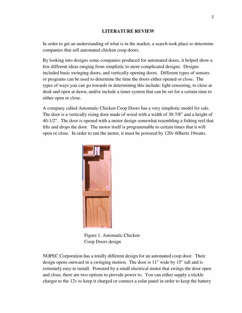
A company called Automatic Chicken Coop Doors has a very simplistic model for sale.
The door is a vertically rising door made of wood with a width of 30-7/8” and a height of
40-1/2”. The door is opened with a motor design somewhat resembling a fishing reel that
lifts and drops the door. The motor itself is programmable to certain times that it will
open or close. In order to run the motor, it must be powered by 120v 60herts 19watts.
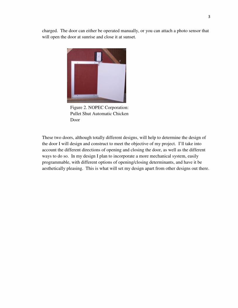
NOPEC Corporation has a totally different design for an automated coop door. Their
design opens outward in a swinging motion. The door is 11” wide by 15” tall and is
extremely easy to install. Powered by a small electrical motor that swings the door open
and close, there are two options to provide power to. You can either supply a trickle
charger to the 12v to keep it charged or connect a solar panel in order to keep the battery
Figure 1. Automatic Chicken
Coop Doors design
3
charged. The door can either be operated manually, or you can attach a photo sensor that
will open the door at sunrise and close it at sunset.
These two doors, although totally different designs, will help to determine the design of
the door I will design and construct to meet the objective of my project. I’ll take into
account the different directions of opening and closing the door, as well as the different
ways to do so. In my design I plan to incorporate a more mechanical system, easily
programmable, with different options of opening/closing determinants, and have it be
aesthetically pleasing. This is what will set my design apart from other designs out there.
Figure 2. NOPEC Corporation:
Pullet Shut Automatic Chicken
Door
4
PROCEDURES AND METHODS
Design Procedure
Main Frame
Aspects that were thought of in order to design the main frame of an automated chicken
coop door involved selecting the type of material, having strength, durability, and
aesthetically pleasing. Therefore I decided to build the main frame out of 18 gauge cold
rolled steel. Using this material allows the door to be extremely strong and durable to
keep out predators. With a good paint job applied to the finished product, it will be both
aesthetically pleasing and able to withstand all weather. The main frame will be made up
of two parts including the center skeleton attached to the front plate, and a removable
back plate.
Opening/Closing of the Door
The design of the door will need to be able to open at a set time in the morning, and close
at a set time in the evening. The door will open and close by the same method a linear
actuator works. An electric motor will be attached to an all thread rod that will rotate in a
fixed position. A coupler nut will be fabricated on the door, when the motor rotates the
rod, the door will move either up or down the all thread rod.
Electronics
In order for the door to open and close at specified times, an electrical circuit must be
designed and attached to the motor. I will be using a 24 VDC 1.7A power supply, 3 120
VAC relays, 2 mini-snap-action switches, and a 125 VAC programmable timer in order
for the door to operate correctly.
5
Construction Procedures
Individual Parts
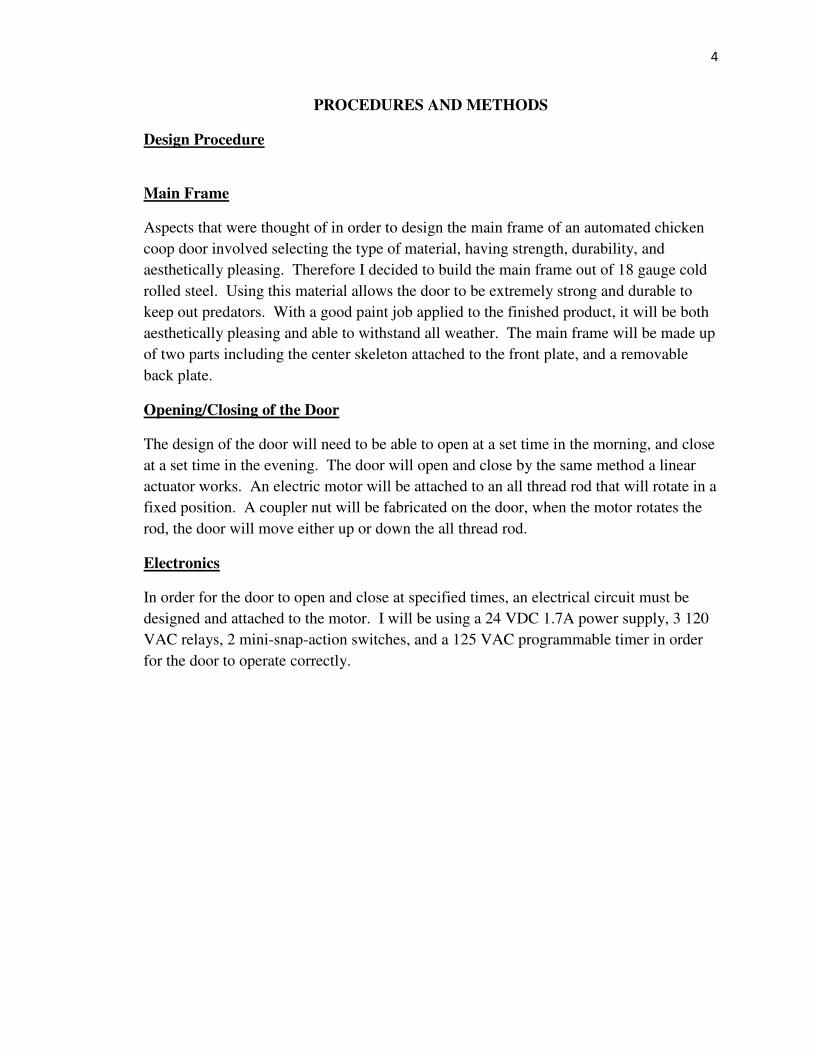
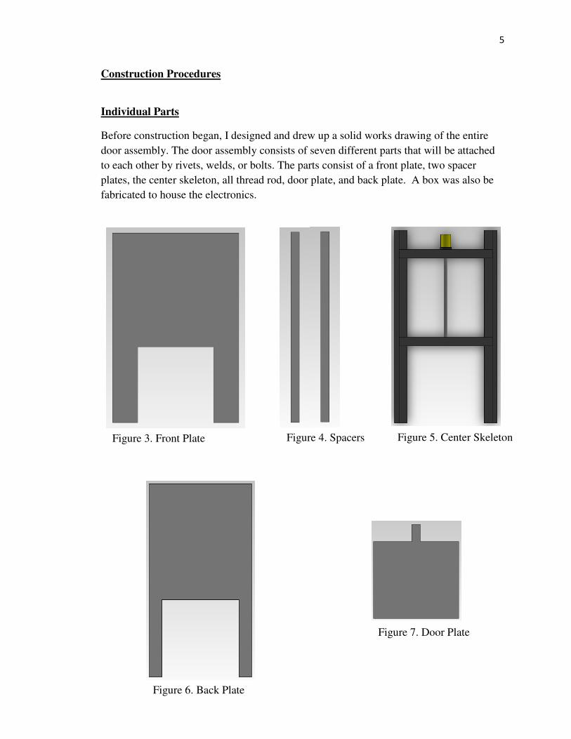
Before construction began, I designed and drew up a solid works drawing of the entire
door assembly. The door assembly consists of seven different parts that will be attached
to each other by rivets, welds, or bolts. The parts consist of a front plate, two spacer
plates, the center skeleton, all thread rod, door plate, and back plate. A box was also be
fabricated to house the electronics.
Figure 3. Front Plate Figure 4. Spacers Figure 5. Center Skeleton
Figure 6. Back Plate
Figure 7. Door Plate
6
Main Frame
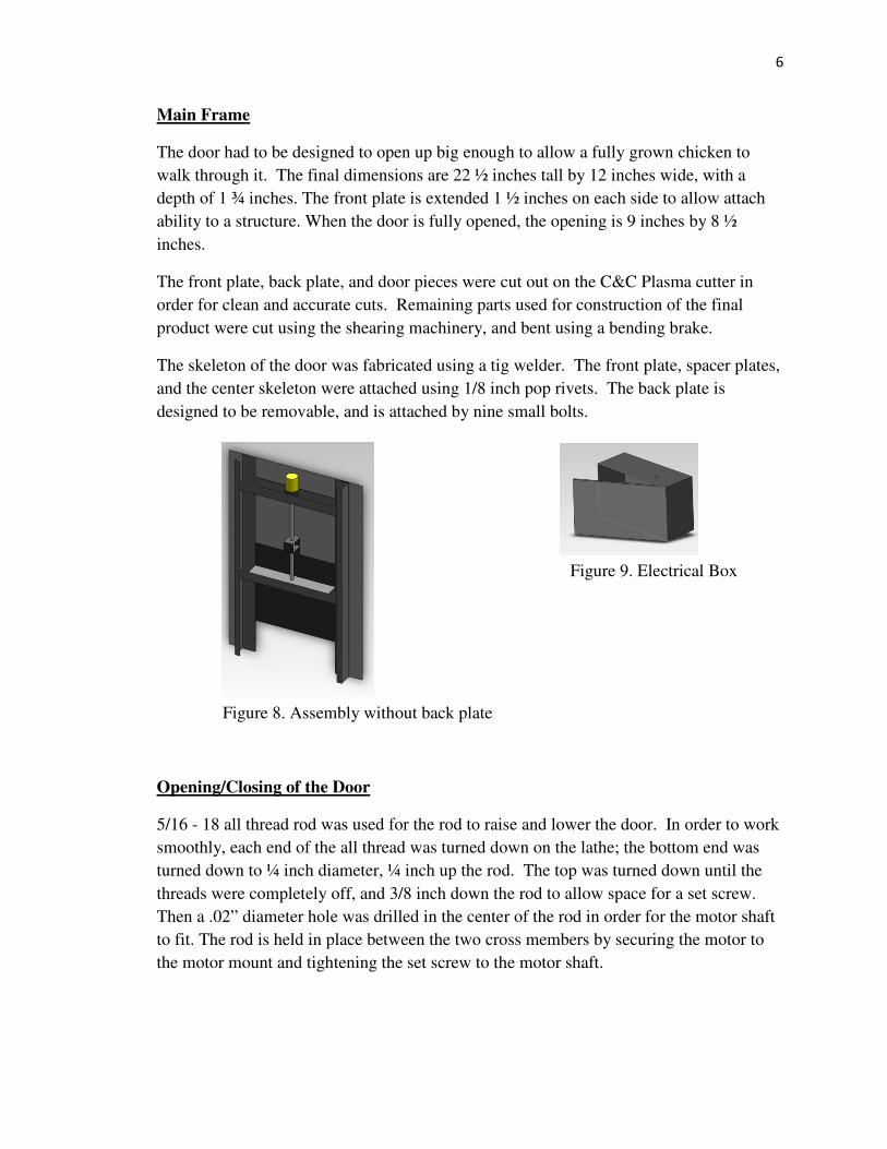
The door had to be designed to open up big enough to allow a fully grown chicken to
walk through it. The final dimensions are 22 ½ inches tall by 12 inches wide, with a
depth of 1 ¾ inches. The front plate is extended 1 ½ inches on each side to allow attach
ability to a structure. When the door is fully opened, the opening is 9 inches by 8 ½
inches.
The front plate, back plate, and door pieces were cut out on the C&C Plasma cutter in
order for clean and accurate cuts. Remaining parts used for construction of the final
product were cut using the shearing machinery, and bent using a bending brake.
The skeleton of the door was fabricated using a tig welder. The front plate, spacer plates,
and the center skeleton were attached using 1/8 inch pop rivets. The back plate is
designed to be removable, and is attached by nine small bolts.
Opening/Closing of the Door
5/16 - 18 all thread rod was used for the rod to raise and lower the door. In order to work
smoothly, each end of the all thread was turned down on the lathe; the bottom end was
turned down to ¼ inch diameter, ¼ inch up the rod. The top was turned down until the
threads were completely off, and 3/8 inch down the rod to allow space for a set screw.
Then a .02” diameter hole was drilled in the center of the rod in order for the motor shaft
to fit. The rod is held in place between the two cross members by securing the motor to
the motor mount and tightening the set screw to the motor shaft.
Figure 8. Assembly without back plate
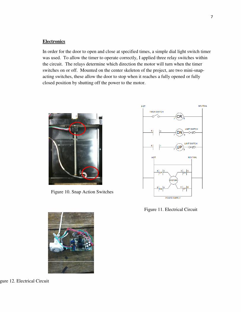
Figure 9. Electrical Box
7
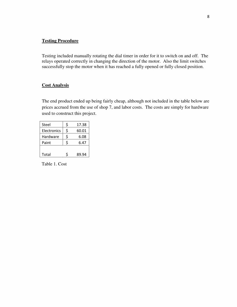
Electronics
In order for the door to open and close at specified times, a simple dial light switch timer
was used. To allow the timer to operate correctly, I applied three relay switches within
the circuit. The relays determine which direction the motor will turn when the timer
switches on or off. Mounted on the center skeleton of the project, are two mini-snap-
acting switches, these allow the door to stop when it reaches a fully opened or fully
closed position by shutting off the power to the motor.
Figure 11. Electrical Circuit
Figure 10. Snap Action Switches
Figure 12. Electrical Circuit
8
Testing Procedure
Testing included manually rotating the dial timer in order for it to switch on and off. The
relays operated correctly in changing the direction of the motor. Also the limit switches
successfully stop the motor when it has reached a fully opened or fully closed position.
Cost Analysis
The end product ended up being fairly cheap, although not included in the table below are
prices accrued from the use of shop 7, and labor costs. The costs are simply for hardware
used to construct this project.
Steel $ 17.38
Electronics $ 60.01
Hardware $ 6.08
Paint $ 6.47
Total $ 89.94
Table 1. Cost
9
RESULTS
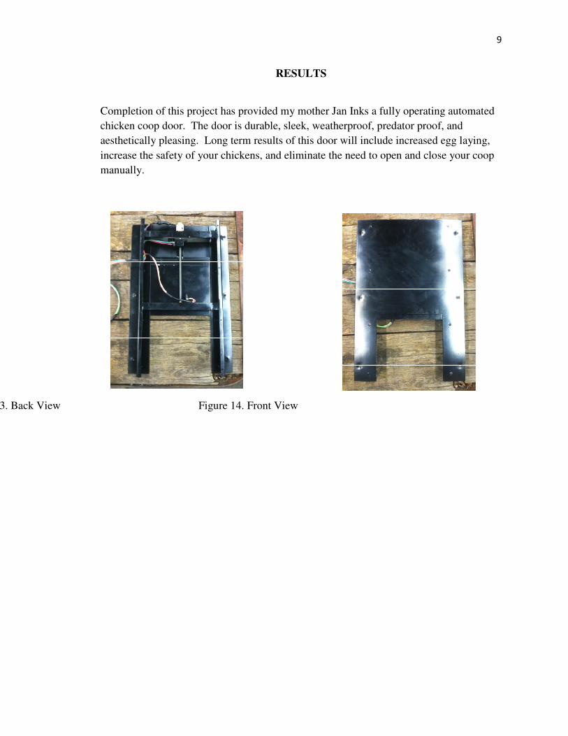
Completion of this project has provided my mother Jan Inks a fully operating automated
chicken coop door. The door is durable, sleek, weatherproof, predator proof, and
aesthetically pleasing. Long term results of this door will include increased egg laying,
increase the safety of your chickens, and eliminate the need to open and close your coop
manually.
Figure 13. Back View Figure 14. Front View
10
DISCUSSION
Overall the design and fabrication of this automated chicken coop door involved certain
skills that were needed. The main difficulty was coming up with a simplistic and small
design to reach the objectives I had set for the project. With the help of Dr. Kelly, the
electronics portion of the project came together very smoothly. The sleek design allowed
me to improve, and learn more fabrication skills. I’m pleased with the end result of the
project, and seeing it work.
11
RECOMMENDATIONS
My main recommendation would be to make the design smaller. The 9 x 8 ½ inch
opening is a little overkill for a fully grown chicken. The door size could easily be
reduced to a 6 x 6 inch cube. Therefore the entire dimension of the door would be 16 ½
inches by 15 inches with a width of 1 ¾ inch.
Also, for a more costly electrical design, using a PLC, and light sensor would make the
door a lot more user friendly. Allowing the door to open at sunrise, and close 45 minutes
after sunset, without needing to be programmed manually by the user.
12
REFERENCES
Smith, James. "Automatic Chicken Coop Door Openers." Automatic Chicken Coop Door
Openers. Automated Chicken Coop Doors. Web. 15 Jan. 2012.
<http://www.automaticchickencoopdoor.com/>.
Ludlow, Rob. "Index." Index. Chicken Doors, 2010. Web. 15 Jan. 2012.
<http://chickendoors.com/>.
13
APPENDIX A
HOW PROJECT MEETS THE REQUIREMENTS FOR THE ASM MAJOR
14
ASM Project Requirements
The ASM senior project included a problem solving experience that incorporated the
application of technology and the organizational skills of business and management, and
quantitative, analytical problem solving. This project addresses these issues as follows.
Application of Agriculture Technology. The project involves the application of
mechanical systems, power transmission, and fabrication technologies.
Application of Business and/or Management Skills. The project involves
business/management skills in the area of machinery management, cost and productivity
analyses, and labor considerations.
Quantitative, Analytical Problem Solving. Quantitative problem solving techniques
include the determination of how much material and hardware will be needed.
Capstone Project Experience
The ASM senior project must incorporate knowledge and skills acquired in earlier
coursework. This project incorporates knowledge/skills from these key courses.
• BRAE 129 Lab Skill/Safety
• BRAE 133 Engineering Graphics
• BRAE 151 AutoCAD
• BRAE 142 Machinery Management
• BRAE 301 Hydraulic/Mechanical Power Systems
• BRAE 302 Servo Hydraulics
• BRAE 321 Ag Safety
• BRAE 324 Principles of Agriculture Electrification
• BRAE 342 Ag Materials
• BRAE 343 Mechanical Systems
• BRAE 418/419 Ag Systems Management
• PM 225 Poultry Management
• CSC 110 Computers and Computer Applications
• ENGL 148 Technical Writing
ASM Approach
Agricultural Systems Management involves the development of solutions to
technological, business or management problems associated with agriculture.
Systems Approach. The project involves the integration of multiple functions,
designing, cutting, welding, and electrification.
15
Interdisciplinary Features. The project touches on aspects of mechanical systems,
agriculture safety, and usability.
Specialized Agriculture Knowledge. The project applies specialized knowledge in the
areas of mechanical and fabrication systems, and agriculture safety.
16
APPENDIX B
CONSTRUCTION DRAWINGS
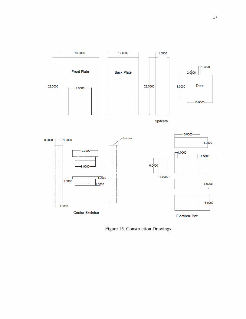
17
Figure 15. Construction Drawings